

Page 1
EN
Page 2
SPECIAL MESSAGE SECTION
PRODUCT SAFETY MARKINGS: Yamaha electronic products
may have either labels similar to the graphics shown below or
molded/stamped facsimiles of these graphics on the
enclosure. The explanation of these graphics appears on this
page. Please observe all cautions indicated on this page and
those indicated in the safety instruction section.
CAUTION
RISK OF ELECTRIC SHOCK
DO NOT OPEN
CAUTION: TO REDUCE THE RISK OF ELECTRIC SHOCK.
DO NOT REMOVE COVER (OR BACK).
NO USER-SERVICEABLE PARTS INSIDE.
REFER SERVICING TO QUALIFIED SERVICE PERSONNEL.
The exclamation point within the equilateral
triangle is intended to alert the user to the
presence of important operating and
maintenance (servicing) instructions in the
literature accompanying the product.
Battery Notice: This product MAY contain a small non-rechargable
battery which (if applicable) is soldered in place. The average life
span of this type of battery is approximately five years. When
replacement becomes necessary, contact a qualified service
representative to perform the replacement.
Warning: Do not attempt to recharge, disassemble, or incinerate this
type of battery. Keep all batteries away from children. Dispose of
used batteries promptly and as regulated by applicable laws. Note: In
some areas, the servicer is required by law to return the defective
parts. However, you do have the option of having the servicer dispose
of these parts for you.
Disposal Notice: Should this product become damaged beyond
repair, or for some reason its useful life is considered to be at an end,
please observe all local, state, and federal regulations that relate to
the disposal of products that contain lead, batteries, plastics, etc.
NOTICE: Service charges incurred due to lack of knowledge relating
to how a function or effect works (when the unit is operating as
designed) are not covered by the manufacturer’s warranty, and are
therefore the owners responsibility. Please study this manual carefully
and consult your dealer before requesting service.
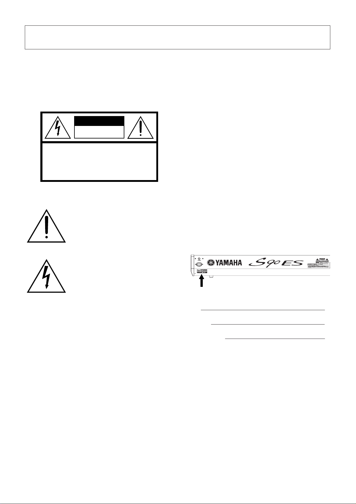
NAME PLATE LOCATION: The graphic below indicates the
location of the name plate. The model number, serial number, power
requirements, etc., are located on this plate. You should record the
model number, serial number, and the date of purchase in the spaces
provided below and retain this manual as a permanent record of your
purchase.
The lightning flash with arrowhead symbol,
within the equilateral triangle, is intended to
alert the user to the presence of uninsulated
“dangerous voltage” within the product’s
enclosure that may be of sufficient magnitude to
constitute a risk of electrical shock.
IMPORTANT NOTICE: All Yamaha electronic products are tested
and approved by an independent safety testing laboratory in order
that you may be sure that when it is properly installed and used in its
normal and customary manner, all foreseeable risks have been
eliminated. DO NOT modify this unit or commission others to do so
unless specifically authorized by Yamaha. Product performance and/
or safety standards may be diminished. Claims filed under the
expressed warranty may be denied if the unit is/has been modified.
Implied warranties may also be affected.
SPECIFICATIONS SUBJECT TO CHANGE: The information
contained in this manual is believed to be correct at the time of
printing. However, Yamaha reserves the right to change or modify any
of the specifications without notice or obligation to update existing
units.
ENVIRONMENTAL ISSUES: Yamaha strives to produce products
that are both user safe and environmentally friendly. We sincerely
believe that our products and the production methods used to
produce them, meet these goals. In keeping with both the letter and
the spirit of the law, we want you to be aware of the following:
Model
Serial No.
Purchase Date
92-469- ➀ (rear)
Page 3

IMPORTANT SAFETY INSTRUCTIONS
INFORMATION RELATING TO PERSONAL INJURY, ELECTRICAL SHOCK,
AND FIRE HAZARD POSSIBILITIES HAS BEEN INCLUDED IN THIS LIST.
WARNING- When using any electrical or electronic product,
basic precautions should always be followed. These precautions
include, but are not limited to, the following:
1. Read all Safety Instructions, Installation Instructions, Special
Message Section items, and any Assembly Instructions found in this
manual BEFORE making any connections, including connection to
the main supply.
2. Do not attempt to service this product beyond that described in
the user-maintenance instructions. All other servicing should be
referred to qualified service personnel.
3. Main Power Supply Verification: Yamaha products are
manufactured specifically for the supply voltage in the area where
they are to be sold. If you should move, or if any doubt exists about
the supply voltage in your area, please contact your dealer for supply
voltage verification and (if applicable) instructions. The required
supply voltage is printed on the name plate. For name plate location,
please refer to the graphic found in the Special Message Section of
this manual.
4. DANGER-Grounding Instructions: This product must be
grounded and therefore has been equipped with a three pin
attachment plug. If this product should malfunction, the ground pin
provides a path of low resistance for electrical current, reducing the
risk of electrical shock. If your wall socket will not accommodate this
type plug, contact an electrician to have the outlet replaced in
accordance with local electrical codes. Do NOT modify the plug or
change the plug to a different type!
5. WARNING: Do not place this product or any other objects on
the power cord or place it in a position where anyone could walk on,
trip over, or roll anything over power or connecting cords of any kind.
The use of an extension cord is not recommended! If you must use an
extension cord, the minimum wire size for a 25’ cord (or less) is 18
AWG. NOTE: The smaller the AWG number, the larger the current
handling capacity. For longer extension cords, consult a local
electrician.
6. Ventilation: Electronic products, unless specifically designed for
enclosed installations, should be placed in locations that do not
interfere with proper ventilation. If instructions for enclosed
installations are not provided, it must be assumed that unobstructed
ventilation is required.
8. This product was NOT designed for use in wet/damp locations
and should not be used near water or exposed to rain. Examples of
wet /damp locations are; near a swimming pool, spa, tub, sink, or wet
basement.
9. This product should be used only with the components supplied
or; a cart,rack, or stand that is recommended by the manufacturer. If
a cart, rack, or stand is used, please observe all safety markings and
instructions that accompany the accessory product.
10. The power supply cord (plug) should be disconnected from
the outlet when electronic products are to be left unused for extended
periods of time. Cords should also be disconnected when there is a
high probability of lightning and/or electrical storm activity.
11. Care should be taken that objects do not fall and liquids are
not spilled into the enclosure through any openings that may exist.
12. Electrical/electronic products should be serviced by a
qualified service person when:
a. The power supply cord has been damaged; or
b. Objects have fallen, been inserted, or liquids have been spilled
into the enclosure through openings; or
c. The product has been exposed to rain; or
d. The product does not operate, exhibits a marked change in
performance; or
e. The product has been dropped, or the enclosure of the product
has been damaged.
13. This product, either alone or in combination with an amplifier
and headphones or speaker/s, may be capable of producing sound
levels that could cause permanent hearing loss. DO NOT operate for
a long period of time at a high volume level or at a level that is
uncomfortable. If you experience any hearing loss or ringing in the
ears, you should consult an audiologist.
IMPORTANT: The louder the sound, the shorter the time period before
damage occurs.
14. Some Yamaha products may have benches and/or accessory
mounting fixtures that are either supplied as a part of the product or
as optional accessories. Some of these items are designed to be
dealer assembled or installed. Please make sure that benches are
stable and any optional fixtures (where applicable) are well secured
BEFORE using. Benches supplied by Yamaha are designed for
seating only. No other uses are recommended.
7. Temperature considerations: Electronic products should be
installed in locations that do not seriously contribute to their operating
temperature. Placement of this product close to heat sources such
as; radiators, heat registers etc., should be avoided.
PLEASE KEEP THIS MANUAL
92-469-3
Page 4
PRECAUTIONS
PLEASE READ CAREFULLY BEFORE PROCEEDING
* Please keep this manual in a safe place for future reference.
WARNING
Always follow the basic precautions listed below to avoid the possibility of serious injury or even death from electrical
shock, short-circuiting, damages, fire or other hazards. These precautions include, but are not limited to, the following:
Power supply/Power cord
• Only use the voltage specified as correct for the instrument. The required
voltage is printed on the name plate of the instrument.
• Check the electric plug periodically and remove any dirt or dust which may have
accumulated on it.
• Use only the supplied power cord/plug.
• Do not place the power cord near heat sources such as heaters or radiators, and
do not excessively bend or otherwise damage the cord, place heavy objects on
it, or place it in a position where anyone could walk on, trip over, or roll anything
over it.
• Be sure to connect to an appropriate outlet with a protective grounding
connection. Improper grounding can result in electrical shock.
Do not open
• This instrument contains no user-serviceable parts. Do not attempt to
disassemble or modify the internal components in any way.
Water warning
• Do not expose the instrument to rain, use it near water or in damp or wet
conditions, or place containers on it containing liquids which might spill into
any openings.
• Never insert or remove an electric plug with wet hands.
Fire warning
• Do not put burning items, such as candles, on the unit.
A burning item may fall over and cause a fire.
If you notice any abnormality
• If the power cord or plug becomes frayed or damaged, or if there is a sudden
loss of sound during use of the instrument, or if any unusual smells or smoke
should appear to be caused by it, immediately turn off the power switch,
disconnect the electric plug from the outlet, and have the instrument inspected
by qualified Yamaha service personnel.
CAUTION
Always follow the basic precautions listed below to avoid the possibility of physical injury to you or others, or damage
to the instrument or other property. These precautions include, but are not limited to, the following:
Power supply/Power cord
• Always connect the three-pin attachment plug to a properly grounded power
source. (For more information about the main power supply, see page 8.)
• When removing the electric plug from the instrument or an outlet, always hold
the plug itself and not the cord. Pulling by the cord can damage it.
• Remove the electric plug from the outlet when the instrument is not to be used
for extended periods of time, or during electrical storms.
• Do not connect the instrument to an electrical outlet using a multiple-connector.
Doing so can result in lower sound quality, or possibly cause overheating in the
outlet.
Location
• Do not expose the instrument to excessive dust or vibrations, or extreme cold or
heat (such as in direct sunlight, near a heater, or in a car during the day) to
prevent the possibility of panel disfiguration or damage to the internal
components.
• Do not use the instrument in the vicinity of a TV, radio, stereo equipment,
mobile phone, or other electric devices. Otherwise, the instrument, TV, or radio
may generate noise.
• Do not place the instrument in an unstable position where it might accidentally
fall over.
• Before moving the instrument, remove all connected cables.
• When setting up the instrument, make sure that the AC outlet you are using is
easily accessible. If some trouble or malfunction occurs, immediately turn off
the power switch and disconnect the plug from the outlet.
• Do not place objects in front of the instrument's air vent, since this may prevent
adequate ventilation of the internal components, and possibly result in the
instrument overheating.
(2)-10 1/2
Page 5

Connections
• Before connecting the instrument to other electronic components, turn off the
power for all components. Before turning the power on or off for all
components, set all volume levels to minimum. Also, be sure to set the volumes
of all components at their minimum levels and gradually raise the volume
controls while playing the instrument to set the desired listening level.
Maintenance
• When cleaning the instrument, use a soft, dry cloth. Do not use paint thinners,
solvents, cleaning fluids, or chemical-impregnated wiping cloths.
Handling caution
• Do not insert a finger or hand in any gaps on the instrument.
• Never insert or drop paper, metallic, or other objects into the gaps on the
keyboard. If this happens, turn off the power immediately and unplug the power
cord from the AC outlet. Then have the instrument inspected by qualified
Yamaha service personnel.
• Do not place vinyl, plastic or rubber objects on the instrument, since this might
discolor the panel or keyboard.
• Do not rest your weight on, or place heavy objects on the instrument, and do not
use excessive force on the buttons, switches or connectors.
• Do not operate the instrument for a long period of time at a high or
uncomfortable volume level, since this can cause permanent hearing loss. If you
experience any hearing loss or ringing in the ears, consult a physician.
Saving data
Saving and backing up your data
• The edited settings are lost when you turn off the power to the instrument
without saving. Make sure to save important data to internal (User) memory (see
page 126).
• Saved data may be lost due to malfunction or incorrect operation. Save
important data to a USB storage device.
• Never attempt to turn off the power while data is being written to internal
memory (while an “Executing...” or “Please keep power on” message is shown).
Turning the power off in this state results in loss of all user data and and may
cause the system to freeze.
This means that this synthesizer may not be able to start up properly, even when
turning the power on next time.
Backing up the USB storage device
•To protect against loss through media damage, we recommend that you save
your important data onto two USB storage devices.
Yamaha cannot be held responsible for damage caused by improper use or modifications to the instrument, or data that is lost or destroyed.
Always turn the power off when the instrument is not in use.
(2)-10 2/2
Page 6

Introduction
Introduction
Congratulations and thank you for your purchase of the Yamaha S90 ES Music Production Synthesizer! You now own one of
the best-sounding, most versatile, and most powerful music production instruments on the planet.
We strove to put virtually all our synthesizer technology and music making know-how into one instrument—and we
succeeded. The new S90 ES not only gives you the latest and greatest sounds and rhythms (as well as the ability to create
your own), it gives you powerful, easy-to-use tools for playing, combining and controlling these dynamic sounds/rhythms—in
real time, as you perform!
Take time to look through this manual carefully. It's packed with important information on how to get the most from this
amazing instrument.
Dive in now and enjoy!
Accessories
The following items have been included with your S90ES. Check to see that you have everything listed
here.
❏ Power cord
❏ Owner’s Manual (this document)
❏ Data List
❏ Sticker label for optional mLAN16E expansion board
The illustrations and LCD screens as shown in this owner’s manual are for instructional purposes only, and
may appear somewhat different from those on your instrument.
This product incorporates and bundles computer programs and contents in which Yamaha owns
copyrights or with respect to which it has license to use others’ copyrights. Such copyrighted materials
include, without limitation, all computer software, style files, MIDI files, WAVE data, musical scores and
sound recordings. Any unauthorized use of such programs and contents outside of personal use is not
permitted under relevant laws. Any violation of copyright has legal consequences. DON’T MAKE,
DISTRIBUTE OR USE ILLEGAL COPIES.
This device is capable of using various types/formats of music data, and it optimizes the data in advance
to the proper format for use with the device. As a result, the data may not be played back precisely as the
creators or composers originally intended.
Copying of the commercially available musical data including but not limited to MIDI data and/or audio
data is strictly prohibited except for your personal use.
• Windows is the registered trademarks of Microsoft
• Apple and Macintosh are trademarks of Apple Computer, Inc., registered in the U.S. and other countries.
• The company names and product names in this Owner’s Manual are the trademarks or registered
trademarks of their respective companies.
6
Owner’s Manual
®
Corporation.
Page 7

Table of Contents
Table of Contents
Introduction.............................................................6
Accessories.............................................................6
Setting up and Playing ...........................................8
Power supply connections........................................... 8
Playing the keyboard ................................................. 10
Modes ........................................................................ 12
Basic instructions....................................................... 13
Main Features ............................................................ 14
Using the Owner’s Manual......................................... 15
The Controls & Connectors 16
Front Panel ................................................................. 16
Rear Panel.................................................................. 18
Using USB storage devices....................................... 20
Basic Operation 21
Restoring the Factory-programmed S90 ES .............. 21
Functions of the MODE buttons ................................. 22
Functions and Sub-Functions .................................... 23
Selecting a Program .................................................. 23
About the editing functions ........................................ 25
Confirmation Message ............................................... 26
Information Display .................................................... 27
Note (Key) settings .................................................... 27
Naming....................................................................... 27
Basic Structure 108
Internal Structure (System Overview)....................... 108
Maintaining data....................................................... 126
Reference 127
Voice mode .............................................................. 127
Performance mode................................................... 149
Multi mode................................................................ 157
Multi Voice mode...................................................... 161
Sequence Play mode ............................................... 162
Utility mode .............................................................. 163
File mode.................................................................. 168
Master mode ............................................................172
Appendix 176
Information Displays................................................. 176
Display Messages....................................................178
About MIDI ...............................................................180
Installing Optional Hardware.................................... 184
Specifications...........................................................188
Troubleshooting .......................................................189
Application Index ..................................................... 193
Index ........................................................................198
Quick Guide 29
Playing the Demo Songs......................................29
Playing the S90 ES................................................30
Voice Play mode ........................................................ 30
Performance Play mode............................................. 34
Using the Arpeggio feature........................................ 39
Using the Controllers on the S90 ES.......................... 41
Editing a Program.................................................44
Editing a Voice ........................................................... 44
Editing a Performance ............................................... 53
Using the Controllers—Advanced Course .........59
Controllers supported by the S90 ES......................... 59
Connecting the Computer and MIDI devices......63
Connections ............................................................... 63
Creating a Song with the Multi mode......................... 70
Using the S90 ES with computer software................. 77
Using mLAN............................................................... 88
Creating Your Original Program Set
(Master mode)........................................................90
Playing back MIDI files
(Sequence Play mode)..........................................96
Using the Plug-in Boards.....................................99
Tips.......................................................................104
Owner’s Manual
7
Page 8
Power supply connections
Setting up and Playing
Power supply connections
Power supply connections
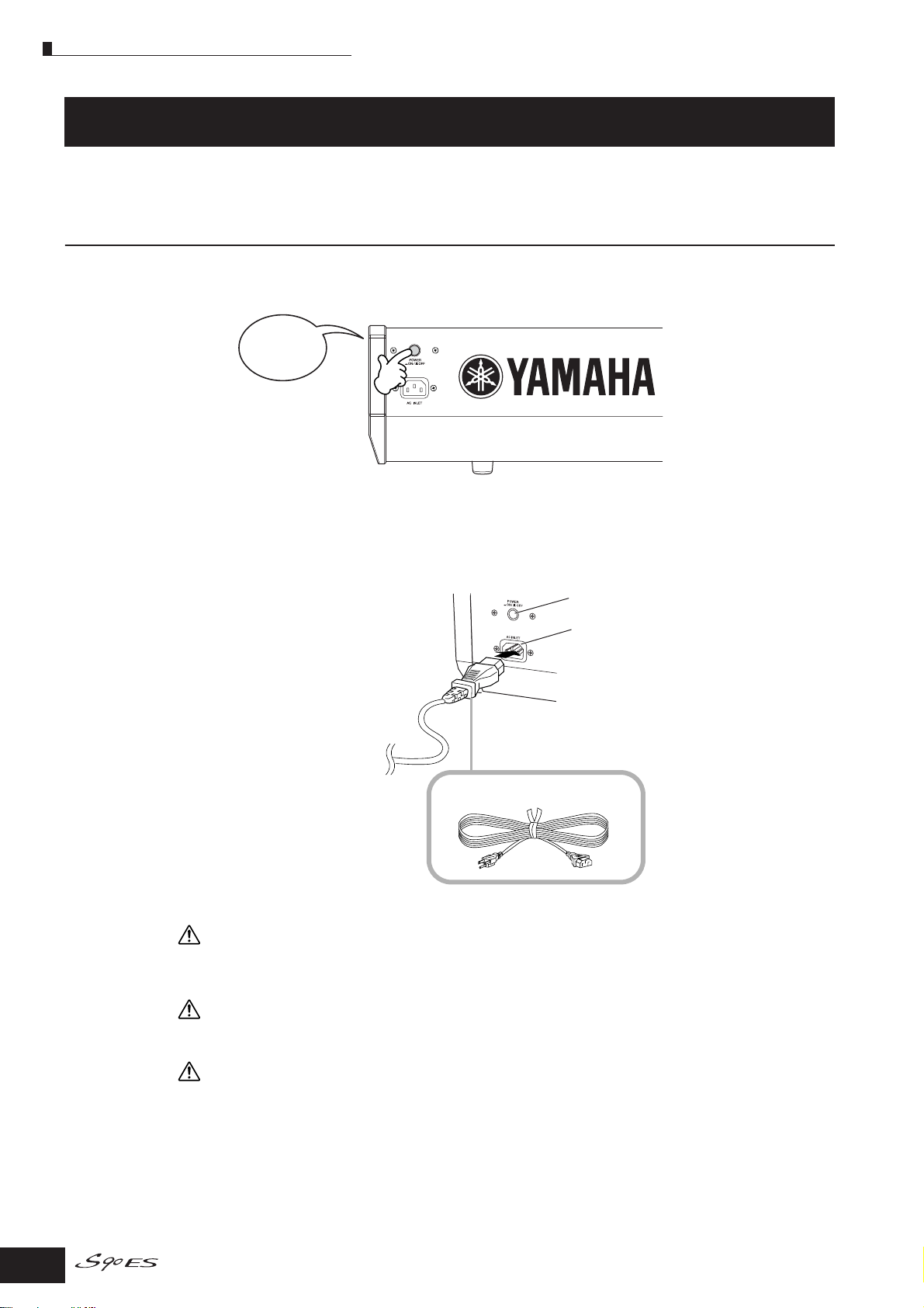
1. Make sure that the instrument’s POWER switch on the rear panel is at the OFF position.
POWER
OFF
2. Connect the supplied power cord to the AC INLET on the instrument’s rear panel.
3. Connect the other end of the power cord to an AC outlet. Make sure your S90 ES meets the
voltage requirement for the country or region in which it is being used.
Power Switch
AC INLET
Power cord (included)
WARNING
Make sure your S90 ES is rated for the AC voltage supplied in the area in which it is to be used (as listed on the rear panel).
Connecting the unit to the wrong AC supply can cause serious damage to the internal circuitry and may even pose a shock
hazard!
WARNING
Use only the AC power cord supplied with the S90 ES. If the supplied cord is lost or damaged and needs to be replaced, contact
your Yamaha dealer. The use of an inappropriate replacement can pose a fire and shock hazard!
WARNING
The type of AC power cord provided with the S90 ES may be different depending on the country in which it is purchased (a third
prong may be provided for grounding purposes). Improper connection of the grounding conductor can create the risk of
electrical shock. Do NO T modify the plug pr o vided with the S90 ES. If the plug will not fit the outlet, have a proper outlet installed
by a qualified electrician. Do not use a plug adapter which defeats the grounding conductor.
8
Owner’s Manual
Page 9
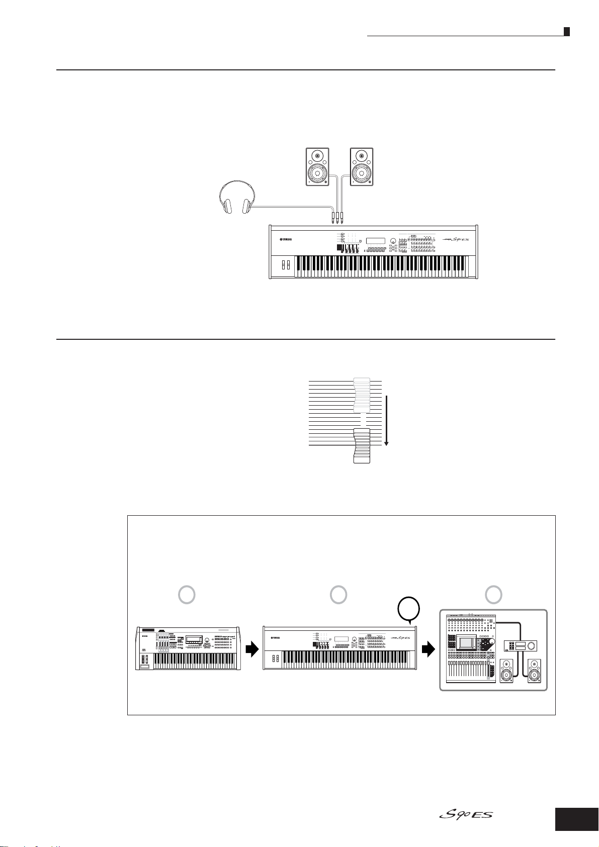
Connecting the speakers or pair of headphones
Powered speaker (Left)
Powered speaker (Right)
Headphones
OUTPUT L/MONO
OUTPUT R
PHONES
S90 ES
MASTER VOLUME
MUSIC PRODUCTION SYNTHESIZER
POWER
ON!!
1 2 3
MIDI master
S90 ES Audio equipment (first mixer, then amplifier)
Since the S90 ES has no built-in speakers, you will need to monitor the sound of the instrument by using
external equipment. Connect a set of headphones, powered speakers, or other playback equipment as
required.
Power supply connections
Turning the power on
Make sure the volume settings of the S90 ES and external devices are turned down to the minimum.
Turn the power on by pressing the [POWER] switch on the S90 ES rear panel, then turn the power on the
amplifiers.
Connecting MIDI devices or a Mixer
Make sure that all volume settings are turned down all the way to the minimum. Then turn on the every device in your setup in the
order of MIDI masters (controllers), MIDI slaves (receivers), then audio equipment (mixers, amplifiers, speakers, etc.).
When powering down the setup, first turn down the volume of each audio device, then switch off each device in the reverse order
(first audio devices, then MIDI).
Owner’s Manual
9
Page 10
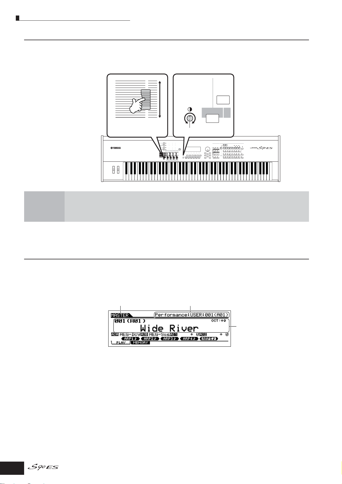
Playing the keyboard
Adjusting the sound and the display contrast
Adjust the volume levels of the S90 ES and the connected amplifier/speaker system. If the display is not
easily visible, use the Contrast control to adjust for optimum visibility.
Adjust the volume with the
MASTER VOLUME slider.
MASTER VOLUME
Now that you’ve set up the S90 ES properly, you’re ready to begin playing it.
n When you are ready to turn off the S90 ES, make sure to switch off the power of the external device (or lower its volume)
before switching off the S90 ES.
Adjust the display contrast with the
Contrast control.
SF1
F1
Contrast control
Playing the keyboard
Playing the sounds
Try playing some of the realistic and dynamic S90 ES sounds from the keyboard now.
When you turn the power on following the directions in “Power supply connections” (page 8), the display
below appears.
n In the default settings, the Master mode is selected. For details about the modes, refer to the section “Modes” on page 12.
Indicates that the Master mode is selected.
In this condition you can play the keyboard and hear the sounds of the selected program. When the
instrument is turned on, the “Wide River” program—featuring a natural, mellow piano sound with a
rhythmic arpeggio and ambient synth—is automatically called up.
Notice the indication “Performance:USER1:001(A01)” at the top right of the display. This indicates that
Performance 001 in User bank 1 is currently selected. A “Performance” is one of the types of programs of
the S90 ES. As described below, the instrument also features other types: Voices and Multis.
n For details about Banks, see page 30. Please note that Performances and Multis have only User Banks (no other banks are
available).
Indicates the type of selected program.
Indicates the name and number of
selected program.
10
Owner’s Manual
Page 11
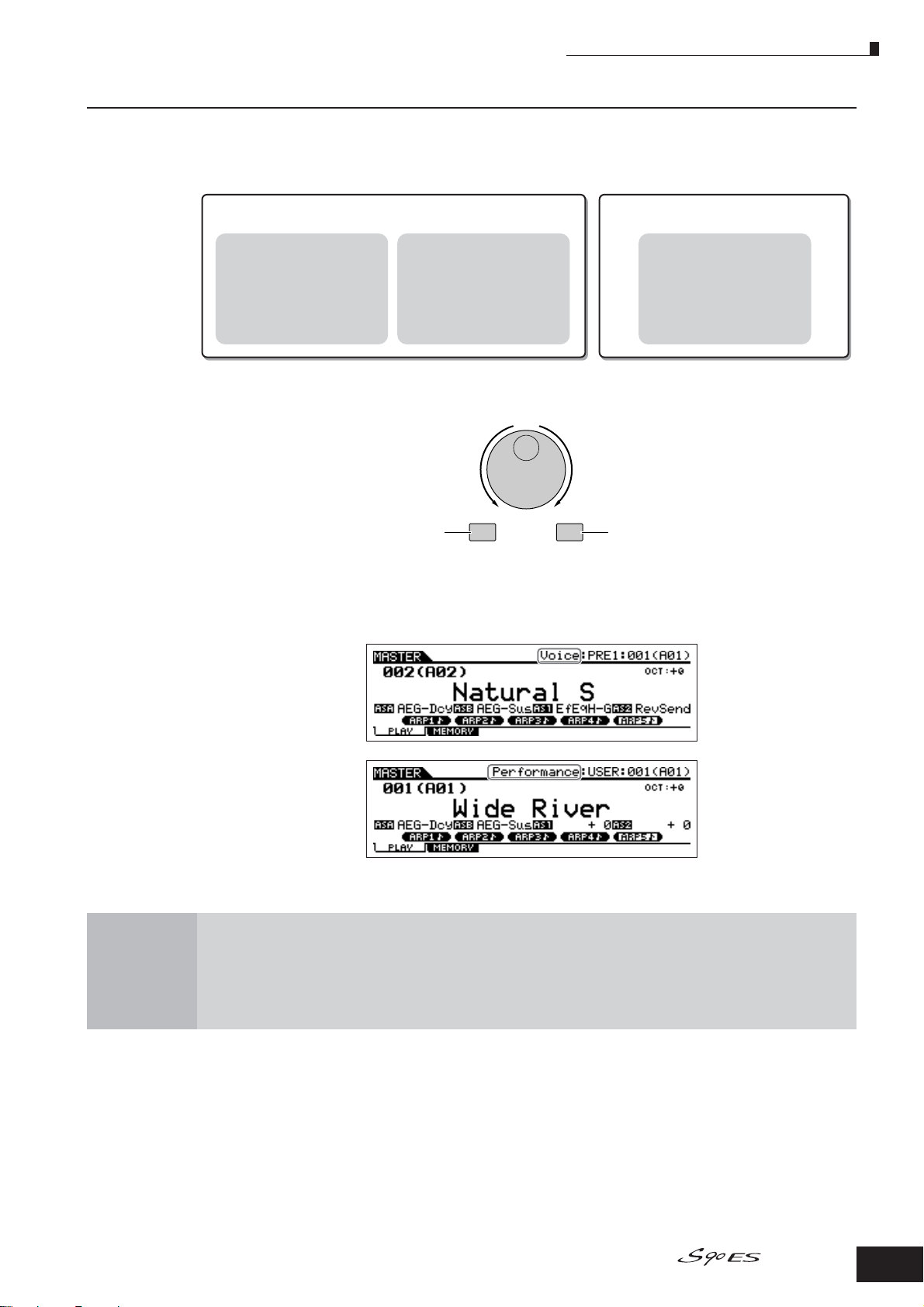
Selecting and playing the sounds
For playing the keyboard
Voice:
This program contains a basic
instrument sound, such as a
piano, guitar, bass guitar, drum
kit, etc.
Performance:
This program allows you to
combine several Voices
together—either in a richly
textured layer, or separately
(as in different sections of the
keyboard) for playing several
different parts simultaneously.
For creating music of multiple parts
Multi:
This program allows you to play
multiple tracks from an external
sequencer, using many different
Voices simultaneously.
DEC/NO INC/YES
Decreases number
Increases number
Increases number
Decreases number
The S90 ES provides three different types of programs for playing the sounds: Voices, Performances, and
Multis. The basic difference among these programs is in their use—for playing the keyboard, or for
creating music with multiple parts.
You can choose from 128 different Voices, Performances, and Multis in the Master mode. To change the
desired Master number, use the [INC/ YES] button, [DEC/NO] button, or the Data dial.
Playing the keyboard
Change the Master number, and then try playing the various Voices or Performance types. When a Voice is
assigned to the selected Master number, “Voice” will appear at the top of the display. When a Performance
is assigned, “Performance” will appear in the display.
n Although a Multi can be used for playing the keyboard, it is primarily intended for creating, recording and playback of multi-part
music. For details about using this function, see page 70.
As you play the various Voices and Performances, notice the differences between them—especially how
some Performances sound exceptionally rich and more complex than Voices.
Here, we’ve introduced the operations in the Master mode that is called up fir st when turning the power on.
The S90 ES has other modes of operation as well. In the next section, we’ll explain about the modes of the
S90 ES and how they are used.
Owner’s Manual
11
Page 12
Modes
Modes
There are several operation modes in the S90 ES, and they can be
selected by using the six mode buttons. The use of the individual
modes depends on your particular musical application. For
playing the keyboard conventionally, the Voice or Performance
mode should be used. If you’re creating music, particularly multipart arrangements, use the Multi mode and Sequence Play mode.
To make global settings for the instrument and back up your
important data, use the Utility and File modes. A special Master
mode is also included for instantly calling up desired modes and
related settings together in one button press, without having to first
select a mode.
1
Playing the keyboard
using a Voice
Voice mode
[VOICE] button
The S90 ES has a wealth of high-quality,
dynamic sounds—also referred to as “Voices. ”
You can play these Voices—one Voice at a
time—from the keyboard in the Voice mode.
The S90 ES also lets you create your own
original Voices.
2
Playing the keyboard
using multiple Voices
Performance mode
[PERFORM] button
In the Performance mode, you can play
several Voices together in a layer, or play
different Voices from separate ranges of the
keyboard. Each of these combinations of
Voices is called a “Performance.” This mode
lets you create richly textured, layered sounds
or play two different parts simultaneously—for
example, piano and bass guitar—and is
particularly useful when performing solo.
VOICE
PERFORM
MASTER
1 2 3
MULTI/
SEQ PLAY
FILE UTILITY
4 5 6
3
EDIT
COMPARE
REMOTE
Creating original
JOB STORE
EFFECT
BYPASS
ARPEGGIO
program sets
Master mode
[MASTER] button
The Master mode can be used in two ways:
• Storing your favorite programs
This lets you register settings that you often
use in the Voice, Performance, or Multi mode,
and instantly recall the mode and custom
settings together in a single button press,
without having to first select a mode.
• Playing as a master keyboard
This lets you divide the keyboard into four
separate sections—just as if you were playing
four different MIDI keyboards.
4
Recording via an
external sequencer
Multi mode
[MULTI/SEQ PLAY] button
The Multi mode lets you use the S90 ES as a
multi-timbral tone generator for sequencer
song playback. By assigning a different Voice
to each track in a song file on your external
sequencer, you can play back complex multipart ensemble recordings.
4
4
4
Playing back MIDI files
SMF (Standard MIDI File) format only
Sequence Play mode
[MULTI/SEQ PLAY] button
In the Sequence Play mode, you can play
back song data created on an external
sequencer, using the S90 ES as a multi-part
tone generator. Multiple SMF files can be
played in order, and files saved to a USB
storage device can be played back directly
without having to load the data to the S90 ES.
n Pressing the [MULTI/SEQ PLAY] button toggles between the Multi mode and Sequence Play mode.
5
Backing up data
File mode
[FILE] button
The File mode lets you save your S90 ES
data to the USB storage device, and allows
you to load the USB device data to the
S90 ES.
You can store your data to the S90 ES;
however, for best safe-keeping, Yamaha
recommends that you back up your important
data to a USB storage devise.
6
Setting the system
parameters
Utility mode
[UTILITY] button
The Utility mode lets you set parameters that
apply to the entire system of the S90 ES.
These parameter settings are applied to all
Voices, Performances, and Multis.
* The settings for each Voice, Performance, or
Multi can be determined in the respective
Voice mode, Performance mode, or Multi
mode.
12
Owner’s Manual
Page 13
Basic instructions
Voices—the basic building blocks of the S90 ES
Voices—created in the Voice mode—are the basic sonic building blocks for the other modes of the S90
ES. The Performance and Multi programs are made up of different Voices, used together for specific
performance or song recording applications. The S90 ES features an exceptionally wide variety of preset
Voices for playing in virtually any musical style. Try searching through the Voices to find your favorites.
Once you’ve explored them and feel comfortable with them, try branching out creatively and use the
editing features to make your own original Voices.
Basic instructions
Selecting a preset Voice
Creating a new Voice
Page 30
Page 44
Combine several Voices to create a Performance or Multi
To play several different Voices together simultaneously, select a Performance. To use the S90 ES as a
multi-timbral tone generator with your sequencer, select a Multi. The S90 ES contains a full set of specially
programmed 128 Performances and 64 Multis. With the help of the Multis, the S90 ES can be used to play
back MIDI song files from a connected USB device.
Selecting a preset Performance
Creating a new Performance
Creating music using a Multi and your computer
Playing back a MIDI file
Page 34
Page 36, 53
Page 70
Page 96
Master mode—Create a master keyboard setup or instantly call up
your desired programs
The Master mode lets you register your favorite Voices, Performances, and Multis together into easy-toselect Master programs. No matter what mode is used—Voice, Performance or Multi—you can have it
instantly and automatically selected when you call up the appropriate Master.
The Master mode can also be used to divide the keyboard into four sections—each with its own Voice—
just as if you were playing four different MIDI keyboards.
Making Master mode settings
Convenient remote control of your computer software
The panel of the S90 ES also serves as a convenient control surface for your computer music system. Use
the buttons and sliders to control the audio mixer and sequencer transport functions in your MIDI/audio
software. This highly intuitive approach gives you hands-on control over your virtual studio—a level of
control that a keyboard and mouse can’t match. These features are available for any computer sequence
software and Multi Part Editor software (Page 77) compatible with the Remote Control function.
Remote-controlling the software
Global settings and data backup
While the Voice, Performance, and Multi modes provide controls for using and editing the programs of the
S90 ES, the Utility mode is the place where you make overall settings for the instrument—for example,
adjusting the transpose and fine tuning controls, or switching between MIDI and USB operation. You can
also archive your important S90 ES data to a USB storage device for safe-keeping.
Making global system settings
Backing up important data
This concludes our short guide to the basic operations and functions of the S90 ES. Enjoy the dynamic,
authentic sounds of the instrument as you continue to play it and create music on it. Make sure to follow the
references above and go on to explore some of the other exciting and powerful features of the S90 ES.
Page 90
Page 77
Page 163
Page 126
Owner’s Manual
13
Page 14

Main Features
Main Features
●Naturally responsive 88-Key Balanced Hammer Effect keyboard (with aftertouch), drawing on our extensive
experience and expertise in piano-making.
●Wide range of dynamic and authentic voices. Use the Category Search function to quickly call up the sounds
you want, based on their instrument type.
●Half Damper function that lets you finely control the decay of the sound—and expressively recreate the
complex charactistics of acoustic instruments, especially piano and stringed instruments.
●Includes the newly developed Damper Resonance—an Insertion effect that reproduces the rich harmonics and
unique sound characteristics of an actual grand piano when using the damper pedal.
●Stretch tuning used on many Voices—the same kind of tuning as used on an actual acoustic piano.
●Arpeggio feature, which automatically plays a variety of sequenced phrases in response to the keys you play.
This function lets you easily call up various melody and rhythm patterns—over 1,700 types—providing instant
inspiration for song creation and performance.
●Versatile Multi mode lets you set up the S90 ES for playing multiple instrument parts from your sequencer
software, giving you all the sounds you need to realize complete, professional-sounding songs. Moreover, the
corresponding Multi Library lets you have the proper instruments for the selected type of music called up
instantly and automatically.
●Extensive effect processing, with Reverb (20 types), Chorus (49 types), eight separate Insertion blocks (each
having two blocks and a total 117 types), Master Effect (8 types), and a digital equalizer (3-band Part EQ and 5band Master EQ).
●Comprehensive real-time control with four Control Sliders—letting you adjust filter, levels, effects, EG, and more,
while you play.
●Master mode—for using the S90 ES as a master keyboard controller (with independent Zones), and for easily
reconfiguring the instrument between Voice/Performance play and Multi play in live applications.
●Remote Control—for operating your favorite sequencer software from the S90 ES.
●Three Modular Synthesis Plug-in System slots, which let you upgrade the S90 ES with a completely new
synthesizer or sound-processing engine. These Plug-in boards give you more voices, more effects, more
polyphony and more instrument parts. Plus, special Plug-in voices have already been programmed and stored
to the S90 ES, ready to be played as soon as you install the proper board.
●A full rear panel of input/output connections provides maximum interfacing flexibility. These include Assignable
Outputs, A/D Inputs, MIDI, and two USB. Moreover, an optional mLAN16E board can be installed.
●Two USB connectors—USB TO HOST for connecting to computer, and USB TO DEVICE for connecting to
storage devices, such as a hard disk drive or flash disk.
●Compatibility with Yamaha's powerful Voice Editor and Multi Part Editor software—featuring comprehensive,
intutive editing of all parameters from your computer.
14
Owner’s Manual
Page 15
Using the Owner’s Manual
Using the Owner’s Manual
Setting up and Playing.........................................................................................................................................Page 8
This section gives you all you need to know about getting started in playing and using your S90 ES—from setting up and
turning on the power to performing basic operations.
The Controls & Connectors...............................................................................................................................Page 16
Use this section to find out about all of the buttons and controls of the S90 ES.
Basic Operation ..................................................................................................................................................Page 21
This section introduces you to the basic operation conventions of this instrument, such as editing values and changing
settings.
Quick Guide.........................................................................................................................................................Page 29
In this tutorial section, you will take a guided tour through the various functions of this instrument, and get some hands-on
experience in playing using it.
Basic Structure .................................................................................................................................................Page 108
This section provides a detailed overview of all of the main functions and features of this instrument, and shows how they fit
together.
Reference...........................................................................................................................................................Page 127
The S90 ES encyclopedia. This section explains all parameters, settings functions, features, modes and operations in full
detail.
Appendix............................................................................................................................................................Page 176
Information on installing options, specifications, error messages, and more.
Troubleshooting................................................................................................................................................Page 189
If the S90 ES does not function as expected or you have some problem with the sound or operation, refer to this section
before calling your Yamaha dealer or service center. Most common problems and their solutions are covered here in a very
simple and easy-to-understand way.
Data List (separate booklet)
This contains various important lists such as the Voice List, Effect List, and MIDI Implementation Chart.
Various pages and menus appear on the LCD display of this instrument depending the selected mode or function.
Throughout this manual, arrows are used in the instructions, indicating in shorthand the process of calling up certain
displays and functions. The example instructions below indicate to 1) press the [VOICE] button, 2) select a Normal
Voice, 3) press the [EDIT] button, 4) select an Element, 5) press the [F1] OSC button, and 6) press the [SF2] OUTPUT
button.
[VOICE]
n When a confirmation message (page 26) or Control Function window (page 42) is shown in the display, press the [EXIT] button to exit from that
→ Normal Voice selection → [EDIT] → Element selection → [F1] OSC → [SF2] OUTPUT
condition, then execute the instructions as in the above example. Likewise, press the [REMOTE] button to exit from the Remote Control mode,
then execute the instructions as in the above example when the S90 ES is in the Remote Control mode.
Owner’s Manual
15
Page 16
The Controls & Connectors
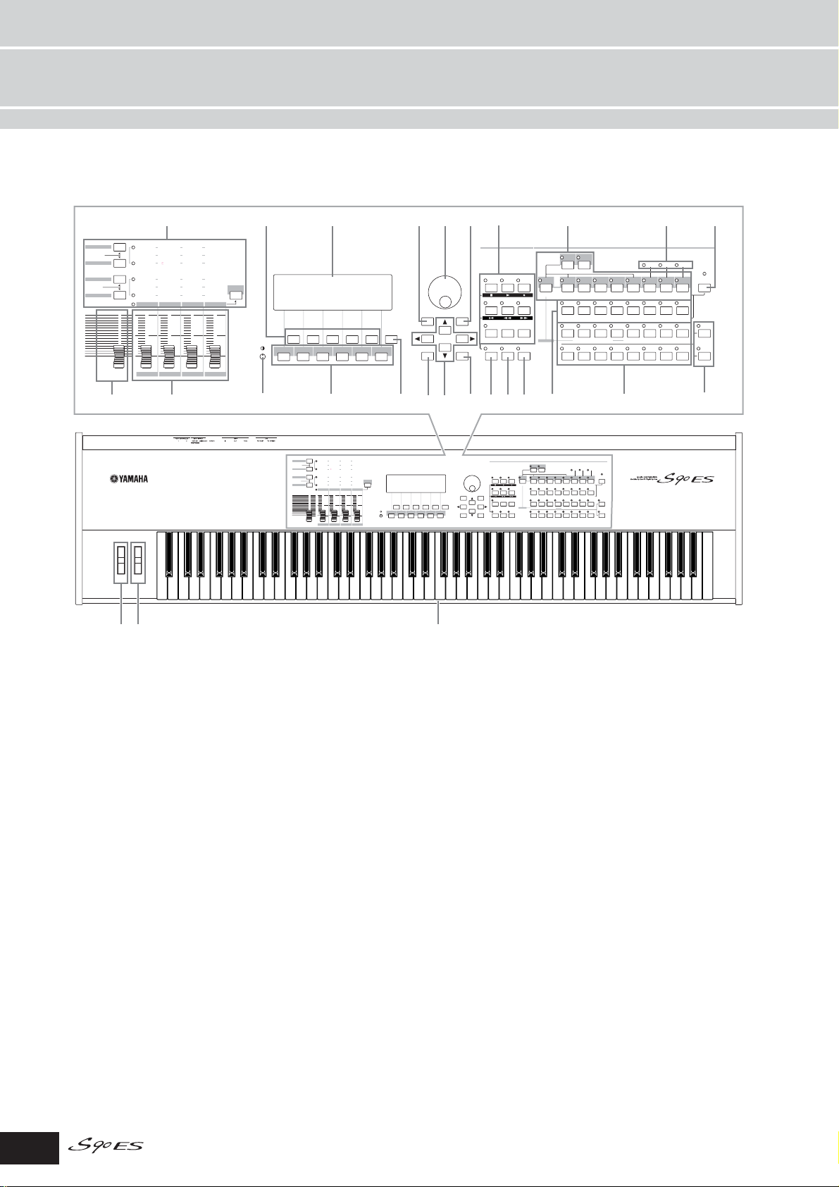
Front Panel
PAN/SEND
ASSIGN
TONE
ARP FX
MEF
EQ
MASTER VOLUME
ASSIGN A ASSIGN B ASSIGN
VOLUME 1
4
6
PAN
REVERB CHORUS TEMPO
1 ASSIGN 2
CUTOFF RESONANCE ATTACK
GATETIME VELOCITY
SWING
1
MEF
MEF
LOW
LOW MID
VOLUME
ZONE 1 ZONE 2 ZONE 3 ZONE 4
RELEASE
UNITMULTIPLY
2 MEF 3 MEF 4
HIGH MID
2 VOLUME 3 VOLUME 4
5
)9
VOLUME
HIGH
2
SF3 SF4 SF5
7
SF1F1SF
F2 F3 F4 F5 F6
8(º¡
PAN/SEND
REVERB CHORUS TEMPO
PAN
ASSIGN
ASSIGN A ASSIGN B ASSIGN
TONE
CUTOFF RESONANCE ATTACK
GATETIME VELOCITY
SWING
ARP FX
MEF
1
2 MEF 3 MEF 4
MEF
MEF
LOW
LOW MID
EQ
VOLUME 1
VOLUME
2 VOLUME 3 VOLUME 4
ZONE 1 ZONE 2 ZONE 3 ZONE 4
MASTER VOLUME
INFORMATION
!
1 ASSIGN 2
RELEASE
UNITMULTIPLY
VOLUME
HIGH MID
HIGH
SF1F1SF
$
DEC/NO
EXIT ENTER
^
2
SF3 SF4 SF5
F2 F3 F4 F5 F6
@
%
MODE
MASTER
PERFORM
VOICE
MULTI/
FILE UTILITY
SEQ PLAY
INC/YES
EDIT
JOB STORE
COMPARE
EFFECT
ARPEGGIO
REMOTE
EXECUTE
BYPASS
&
MODE
DRUM
MASTER
PERFORM
VOICE
KITS
FAVORITES
MULTI/
FILE UTILITY
SEQ PLAY
DEC/NO
INC/YES
EDIT
EXIT ENTER
JOB STORE
COMPARE
COMMON
EFFECT
ARPEGGIO
REMOTE
BYPASS
EXECUTE
INFORMATION
DRUM
KITS
FAVORITES
COMMON
£
PROGRAM
USER 1
USER 2
PRE 3
PRE 2
PRE 4
PRE 1
GUITAR/
A. PIANO KEYBOARD ORGAN
PLUCKED
A
BCDEFG
SYN PAD/
SYN COMP
CHROMATIC
SYN LEAD
PERCUSSION
CHOIR
4321
ELEMENT/PERF. PART/ZONE
11
9
12 13
10
USER 1
PRE 1
A. PIANO KEYBOARD ORGAN
A
SYN LEAD
9
GM
BASS
DRUM/
PERCUSSION
5
PROGRAM
USER 2
PRE 3
PRE 2
BCDE FG
SYN PAD/
SYN COMP
CHOIR
3
21
ELEMENT/PERF. PART/ZONE
11
10
PRE 4
GUITAR/
PLUCKED
CHROMATIC
PERCUSSION
4
12 13
BASS
DRUM/
PERCUSSION
SLOT
GM
PLG 1
STRINGS
5
¢
1
SLOT
SLOT 3
SLOT 2
CATEGORY
PLG 1
PLG 2
PLG 3
SEARCH
STRINGS
BRASS
REED/PIPE
H
MUSICAL FX
SE
COMBI
TRACK
876
SELECT
MUTE
14
16
15
SOLO
1
SE
6
14
A-1 B-1 C0 D0 E0 F0 G0 A0 B0 C1 D1 E1 F1 G1 A1 B1 C2 D2 E2 F2 G2 A2 B2 C3 D3 E3 F3 G3 A3 B3 C4 D4 E4 F4 G4 A4 B5 C5 D5 E5 F5 G5 A5 B5 C6 D6 E6 F6 G6 A6 B6 C7
321
¶™#*
SLOT 2
PLG 2
BRASS
MUSICAL FX
∞
SLOT 3
CATEGORY
PLG 3
SEARCH
REED/PIPE
H
COMBI
TRACK
8
7
SELECT
MUTE
16
15
SOLO
§
n When setting the following parameter to “0,” each key corresponds to the note name shown in the illustrations. [UTILITY] → [F1] GENERAL → [SF2]
KBD → Octave. Refer to this illustration when setting parameters having note name values, such as Note Limit.
1 Keyboard
The keyboard is equipped with a touch response
feature (both initial touch and aftertouch). With initial
touch, the instrument senses how strongly or softly you
play the keys, and uses that playing strength to affect
the sound in various ways, depending on the selected
voice. With aftertouch, the instrument senses how much
pressure you apply to the keys while playing, and uses
that pressure to affect the sound in various ways,
depending on the selected voice.
Moreover, any of a variety of functions can be assigned
to aftertouch for each voice (page 62).
2 Pitch bend wheel Page 41
Controls the pitch bend effect. You can also assign
other functions to this controller.
3 Modulation wheel Page 41
Controls the modulation effect. You can also assign
other functions to this controller.
4 [MASTER VOLUME] slider
Adjusts the master volume. Move the slider upwards to
raise the output level from the OUTPUT L/R jacks and
the PHONES jack.
5 Control sliders 1 - 4 Page 42
These four highly versatile sliders let you adjust various
aspects or parameters of the current Voice. Use the
Control function buttons above to change the parameter
set for the Control sliders.
n If all of the Control sliders are set to the minimum, you may not hear
any sound from the instrument, even when playing the keyboard. If
this is the case, raise all the sliders to a suitable level.
n The [MASTER VOLUME] slider adjusts the output level from this
instrument. On the other hand, the volume adjustment by Control
slider adjusts the MIDI volume value for the corresponding Element
or Part.
6 Control function buttons Page 43
Use the Control function buttons to change the
parameter set for the Control sliders.
7 LCD Contrast control Page 10
Use this control to set the LCD display for optimum
legibility.
8 [F1] - [F6] (Function) buttons Page 23
These buttons located directly below the LCD display
call up the corresponding functions indicated in the
display. In the display hierarchy, these functions [F] rank
just below the modes.
16
Owner’s Manual
Page 17

Front Panel
9 [SF1] - [SF6] (Sub Function) buttons Page 23
These buttons located directly below the LCD display
call up the corresponding sub functions indicated in the
display. In the display hierarchy, these sub functions
[SF] rank just below the functions [F].
These buttons can be also used to store/recall the
Arpeggio type in each Play mode. (page 39)
) LCD Display
The large backlit LCD displays the parameters and
values related to the currently selected operation or
mode.
! [INFORMATION] button Page 27
For calling up a special “help” feature that shows
information about the currently selected mode. You can
go back to the previous display by pressing this button
again or pressing any other button.
Depending on the selected display, this button may be
used to call up a window for inputting characters (page
27), or for selecting keys (page 53).
@ Data dial Page 25
For editing the currently selected parameter. To increase
the value, turn the dial right (clockwise); to decrease the
value, turn the dial left (counter-clockwise). If a
parameter with a wide value range is selected, you can
change the value in broader strokes by quickly turning
the dial.
# [INC/YES] button Page 25
For increasing the value of the currently selected
parameter. Also use it to actually execute a Job or a
Store operation.
$ [DEC/NO] button Page 25
For decreasing the value of the currently selected
parameter. Also use it to cancel a Job or a Store
operation.
n You can also use the [INC/YES] and [DEC/NO] buttons to quickly
move through parameter values in 10-unit jumps, especially those
with large ranges. Simply hold down one of the buttons (of the
direction you want to jump), and simultaneously press the other. For
example, to jump in the positive direction, hold down the [INC/YES]
button and press [DEC/NO].
& [ENTER] button
Use this button to execute a Job or a Store operation.
Also use this button to actually enter a number when
selecting a Memory or Bank for Voice or Performance.
In the File mode, use this button to go to the next lowest
level in the selected directory.
n In the File mode, the [EXIT] and [ENTER] buttons may be used to
move folders in the USB storage device.
* MODE buttons Page 22
These buttons select the operating modes (e.g., Voice
mode).
( [REMOTE] button Page 78
The Remote mode lets you control sequencer software
on your computer from the panel controls of the
instrument. Turn the [REMOTE] button on to enter the
Remote mode.
n When setting the MIDI IN/OUT parameter to “MIDI” ([UTILITY] →
[F5] MIDI → [SF4] OTHER) or setting both of Mode A and Mode B
to “off” ([UTILITY] → [F4] CTL ASN → [SF4] REMOTE), you cannot
enter the Remote mode even by pressing the [REMOTE] button. Set
these parameters to appropriate values (page 78) then enter the
Remote mode.
º [EFFECT BYPASS] button Page 119
The extensive effect section of the instrument provides
Insertion effects (eight sets, with two effect units per
set), System effects (Reverb and Chorus), and Master
effects.
The [EFFECT BYPASS] button enables you to turn the
corresponding effect blocks on or off with a single
touch. From the following display, you can select the
specific effect(s) to be bypassed when the [EFFECT
BYPASS] button. [UTILITY] → [F1] GENERAL → [SF3]
EF BYPS display
n If you install an optional Effect Plug-in Board (PLG100-VH), Plug-in
Insertion effects can also be used (page 103).
¡ [ARPEGGIO] button Page 39
Press this button to enable or disable playback of the
Arpeggio for each Voice, Performance, Multi. If the
Arpeggio Switch of the selected part is set to off in the
Performance/Multi mode, however, pressing this button
has no effect.
Connectors
The Controls &
% Cursor buttons Page 25
The cursor buttons move the “cursor” around the LCD
display screen, highlighting and selecting the various
parameters.
^ [EXIT] button Page 22
The menus and displays of this synthesizer are
organized according to a hierarchical structure.
Press this button to exit from the current display and
return to the previous level in the hierarchy.
™ Bank buttons Pages 30, 32
Each button selects a Voice Bank. When the
[CATEGORY SEARCH] button is turned on, these
buttons can be used to select the desired category
(printed below each button).
£ Group [A] - [H] buttons Pages 31, 32
Each button selects a Voice or Performance Group.
When the [CATEGORY SEARCH] button is turned on,
these buttons can be used to select the desired
category (printed below each button).
¢ Number [1] - [16] buttons
Use of these buttons differs depending on the on/off
status of the [TRACK SELECT] and [MUTE] buttons.
Owner’s Manual
17
Page 18
Connectors
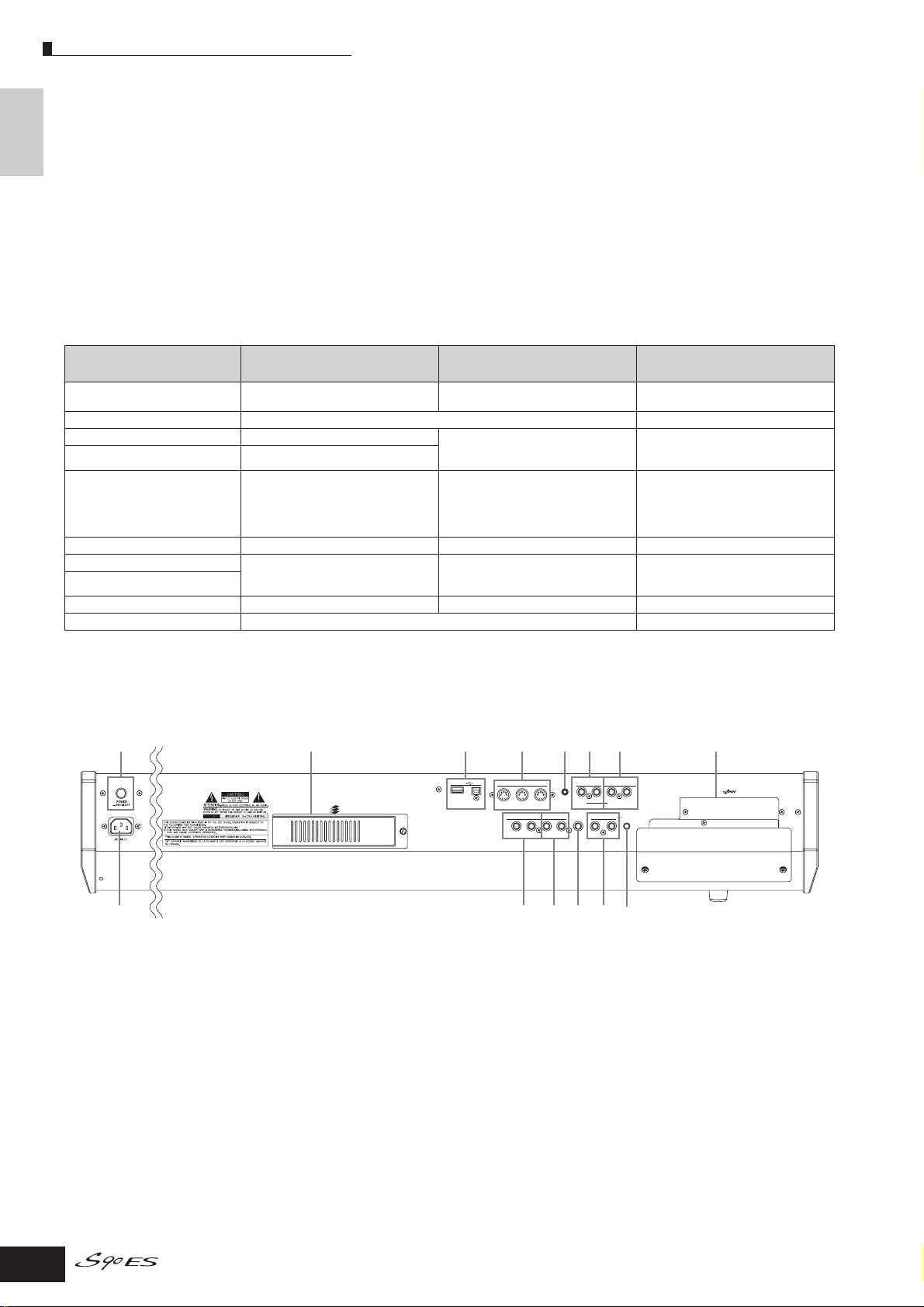
Rear Panel
The Controls &
∞ [CATEGORY SEARCH] button Page 32
When this button is turned on, the lower row of Bank
buttons (labeled A.PIANO—REED/PIPE below the
buttons) and the Group buttons can be used to select
the Voice/Performance category.
§ [TRACK SELECT] button Page 104
[MUTE] button Page 105
The buttons enable you to switch the function of Number
[1] - [16] buttons. For details, see the “
¢ Number [1] -
[16] buttons.”
■ Functions of the Number [1] - [16] buttons
¶ SLOT 1 - 3 lamps Page 99
These three lamps show the installation status of the
Plug-in Boards. If the Plug-in Board has been correctly
installed, the corresponding SLOT lamp will light.
n The Vocal Harmony Plug-in Board (PLG100-VH) can be installed
only to slot 1.
n The Multi part Plug-in Board (PLG100-XG) can be installed only to
slot 3.
When [TRACK SELECT] button is on When [MUTE] button is on
Voice Play mode Keyboard transmit channel setting — Voice selection, according to Groups
When both [TRACK SELECT]
and [MUTE] buttons are off
A - H
Voice Edit mode Element selection (1 - 4) and Element Mute setting (9 - 12) —
Performance Play mode Keyboard transmit channel setting Performance Part Mute setting (1 - 4) Performance or Voice selection (if
Performance Edit mode Performance part selection (1 - 4)
Master Play mode
Keyboard transmit channel setting (when
memorizing the Voice mode or
Performance mode to the current Master)
Part Mute setting (when registering a
Performance or a Multi)
cursor is located at Voice name),
according to Groups A - H
Master selection, according to Groups
A - H
or Multi Part selection (when memorizing
the Multi mode to the current Master)
Master Edit mode Zone selection (1 - 4) — —
Multi Play mode Part selection Part Mute setting Multi or Voice selection (if cursor is
Multi Edit mode
located at Voice name), according to
Groups A - D
Sequence Play mode Keyboard transmit channel setting Part Mute setting —
Multi Voice Edit mode Element selection (1 - 4) and Element Mute setting (9 - 12) —
Rear Panel
145$67 83
Plug-in SLOT
USB
TO DEVICE
GREEN
YELLOW
ORANGE
TO HOST
MIDI
OUT
THRU
ASSIGNABLE OUTPUT
L
RR
FOOT SWITCH
FOOT CONTROLLER
FOOT PEDAL
R
A/D INPUT
1
2
GAIN
L
ASSIGNABLE SUSTAIN
BREATH
IN
PHONES
OUTPUT
L/MONO
2 #!9) @
1 POWER Switch
Use this to switch the synthesizer on or off.
2 AC INLET (AC Power Cord Socket) Page 8
Be sure the plug the AC power cord into this socket
before plugging the power cord into an AC outlet. Use
only the AC power cord supplied with the S90 ES.
3 Plug-in Board Slots 1 - 3 (Plug-in Boards
cover)
Installing an optional Plug-in Board to the S90 ES lets
you greatly expand the sonic palette of the instrument.
Up to three boards can be installed to the S90 ES’s rear
panel.
18
Owner’s Manual
Page 184
4 USB connectors Page 67
This instrument is equipped with two types of USB
connectors on the rear panel—USB TO HOST and USB
TO DEVICE. The USB TO HOST connector is used to
connect this instrument to the computer via the USB
cable. The USB connection between the instrument and
the computer can only be used for transfer of MIDI data.
Unlike MIDI, USB can handle multiple ports via a single
cable. The USB connection can only be used for
transfer of MIDI data. No audio data can be transferred
via USB.
The USB TO DEVICE connector is used to connect this
instrument to a USB storage device (hard disk drive,
CD-ROM drive, MO drive, flash disk, etc.) via the USB
cable. This lets you save the data created on this
Page 19
Rear Panel
mLAN EXPANSION BOARD mLAN16E
ACTIVE
MADE IN JAPAN
IEEE1394
21
1
instrument to the external USB storage device and load
the data from the external USB storage device to the
instrument. Save and Load operations are executed in
the File mode. (Pages 50, 56, 76)
n For details about USB, see page 20 .
USB
USB is an abbreviation for Universal Serial Bus. It is a serial
interface for connecting a computer with peripheral devices,
and enables much faster data transfer compared to
conventional serial port connections.
5 MIDI IN/OUT/THRU connectors Page 65
MIDI IN receives MIDI messages from an external MIDI
device. Use this connector to control the synthesizer
from an external MIDI device. MIDI OUT is for
transmitting all control, performance and playback data
from the S90 ES to another MIDI device, such as an
external sequencer.
You can also play the external tone generator by using
the S90 ES and control the external MIDI device.
MIDI THRU is simply for redirecting any received MIDI
data (via MIDI IN) to connected devices, allowing
convenient chaining of additional MIDI instruments.
6 BREATH Controller jack Page 59
Connect an optional breath controller BC3 here. You can
use the Breath Controller to change the output level or
tone of the sounds according to the strength of your
breath.
7 FOOT SWITCH jacks Page 59
For connection of optional FC3, FC4 or FC5
Footswitches.
When connected to the SUSTAIN jack, the Footswitch
controls sustain.
When connected to ASSIGNABLE, it can control one of
various different assignable functions.
n The SUSTAIN jack can be used with the FC3, FC4, or FC5. The
ASSIGNABLE jack can be used with the FC4 or FC5.
) OUTPUT L/MONO & R jacks Pages 9, 63
Line level audio signals are output via these phone
jacks. For monophonic output, use just the L/MONO
jack.
! PHONES jack Page 9
For connection to a pair of stereo headphones.
@ A/D INPUT jacks Page 38
External audio signals can be input via these phone
jacks (1/4" mono phone plug). Various devices such as
microphone, guitar, bass, CD player, synthesizer can be
connected to these jacks and their audio input signal
can be sounded as the AUDIO IN part of the
Performance or Multi.
For stereo signals (such as from audio equipment), use
both jacks. For mono signals (such as from a
microphone or guitar), use only the L jack.
# GAIN knob Page 38
For adjusting the input gain of the audio at the A/D
INPUT jacks (above). Depending on the connected
device (microphone, CD player, etc.), you may need to
adjust this for optimum level.
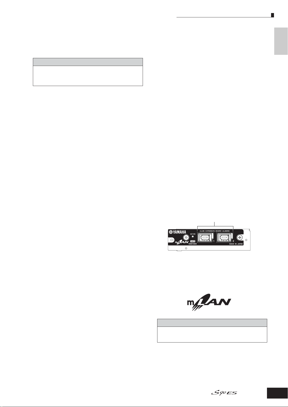
$ mLAN expansion board (mLAN16E) cover
Pages 88, 184
The mLAN expansion board (mLAN16E) sold separately
can be installed to this instrument.
With the mLAN16E board, you can conveniently and
easily hook up your S90 ES to other mLAN compatible
instruments or devices.
■ When the optional mLAN16E has been installed:
Connectors
The Controls &
8 FOOT CONTROLLER 1 and 2 jacks Page 59
An optional foot controller (FC7, etc.) can be connected
here. Each jack lets you continuously control one of
various different assignable functions — such as
volume, tone, pitch, or other aspects of the sound.
9 ASSIGNABLE OUT L and R jacks Page 63
Line level audio signals are output from this instrument
via these phone jacks (1/4" mono phone plug).
These outputs are independent of the main output (at
the L/MONO and R jacks below), and can be freely
assigned to any of the Drum Voice keys or the Parts.
This lets you route specific Voices or sounds for
processing with a favorite outboard effect unit.
The parts which can be assigned to these jacks are as
follows:
• Drum Voice key to which the drum/percussion instrument is
assigned
• Any Part of a Performance*
• Any Part of a Multi*
* Including the Audio Input Part
n The illustration above shows the panel of the mLAN16E expansion
board with the included sticker label affixed. Make sure to attach
this label to the mLAN16E (page 187).
1 mLAN (IEEE1394) connectors 1, 2
For connecting mLAN devices or IEEE1394-compatible
devices via IEEE1394 standard (6-pin) cables.
mLAN
“mLAN” is a digital network designed for musical
applications. It uses and extends the industry standard IEEE
1394 high performance serial bus.
* The name “mLAN” and its logo (above) are trademarks.
Owner’s Manual
19
Page 20
Connectors
Using USB storage devices
The Controls &
Using USB storage devices
When using USB storage devices, make sure to connect them to the USB TO DEVICE connector, and follow the important
precautions below.
■ Compatible USB devices
Connect only a USB storage device (such as hard disk, CDROM, flash disk and other drives) to the USB TO DEVICE
connector. Other devices such as a computer keyboard or
mouse cannot be used.
Both bus-powered (powered by the host device) or self
powered (battery or external power supply) types can be
used.
The S90 ES does not necessarily support all commercially
available USB storage devices. Yamaha cannot guarantee
operation of USB storage devices that you purchase.
Before purchasing USB storage devices, please consult
your Yamaha dealer, or an authorized Yamaha distributor
(see list at end of the Owner’s Manual) for advice, or see the
following website:
http://www.yamahasynth.com/
n Although CD-R/W drives can be used to load data to the instrument,
they cannot be used for saving data. However, you can transfer
data to a computer and save data to a CD using the CD-R/W drive
on the computer.
■ Formatting USB storage media
When a USB storage device is connected or media is
inserted, a “USB device unformatted.” message may
appear in the LCD display, indicating that the device or
media must be formatted for use. Execute the Format
operation in the File mode (Page 168).
Precautions when using the USB TO DEVICE
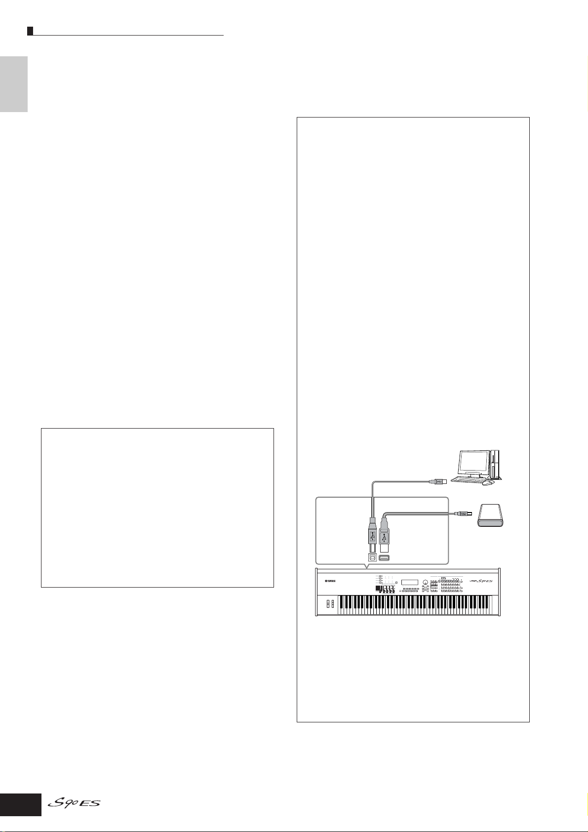
USB connector types
There are two different types of USB connectors, and
the rear panel of the instrument features both. Take
care not to confuse the two.
USB TO HOST connector
This type is used to connect the instrument to a
computer, and allows you to transfer MIDI data
between the devices. The USB connection between
the instrument and the computer can only be used for
transfer of MIDI data. Unlike MIDI, USB can handle
multiple ports via a single cable.
USB cables have different connectors on each end:
the A type and the B type. Connect the A type to your
computer and the B type to the USB TO HOST
connector.
USB TO DEVICE connector
This type is used to connect the instrument to a USB
storage device, and allows you to save data you’ve
created to the connected device, as well as load data
from the connected device. This lets you save the data
created on this instrument to the external USB storage
device and load the data from the external USB
storage device to the instrument. Save and Load
operations are executed in the File mode (page 168).
USB cables have different connectors on each end:
the A type and the B type. Connect the A type to the
USB TO DEVICE connector and the B type to the USB
storage device.
connector
Never turn the USB device’s power on/off and never
plug/unplug the USB cable when the connected USB
storage device is the self powered type. Doing so may
result in the operation of the synthesizer “freezing” or
hanging up.
While the instrument is accessing data (such as in the
Save, Load and Delete operations in the File mode),
do NOT unplug the USB cable, do NOT remove the
media from the device, and do NOT turn the power off
to either device. Doing so may corrupt the data on
either or both devices.
B type
USB TO HOST
connector
MIDI data transfer
Saving/Loading data in
the File mode (page 168)
A type
USB TO DEVICE
connector
Connecting to a computer
Connecting to a USB
storage device (hard
disk, CD-ROM, flash
disk and other drives)
■ To protect your data (Write-protect):
To prevent important data from being inadvertently erased,
apply the write-protect provided with each storage device
or media.
If you are saving data to the USB storage device, make sure
to remove the write-protect.
20
Owner’s Manual
S90 ES
n The computer cannot access the USB storage device
connected to the S90 ES’s USB TO DEVICE connector, even
if connecting as shown above. Only from the File mode on
the instrument itself can you access the data on the USB
storage device connected to the USB TO DEVICE connector.
n Though the S90 ES supports the USB 1.1 standard, you can
connect and use a USB 2.0 storage device with the S90 ES.
However, note that the transfer speed complies to USB 1.1.
Page 21
Basic Operation
In this section you’ll learn about the fundamental operations of the S90 ES—the use of the panel controls and how to execute
basic functions such as selecting programs, naming programs/files, and using the keyboard to directly enter
certain values.
This section starts off with the Factory Set operation, which allows you to restore the instrument to its original condition—in
case you’ve inadvertently changed any important settings.
Restoring the Factory-programmed S90 ES
The S90 ES has a Factory Set function for restoring your S90 ES’s memory to the factory default settings.
This lets you restore the synthesizer’s default User Voices, Performances and Multis, as well as its System and other settings.
CAUTION
Keep in mind that once you edit any settings, the corresponding factory defaults will be overwritten and lost. Make sure you are not overwriting any
important data. You should back up any important data to the USB device beforehand (page 126).
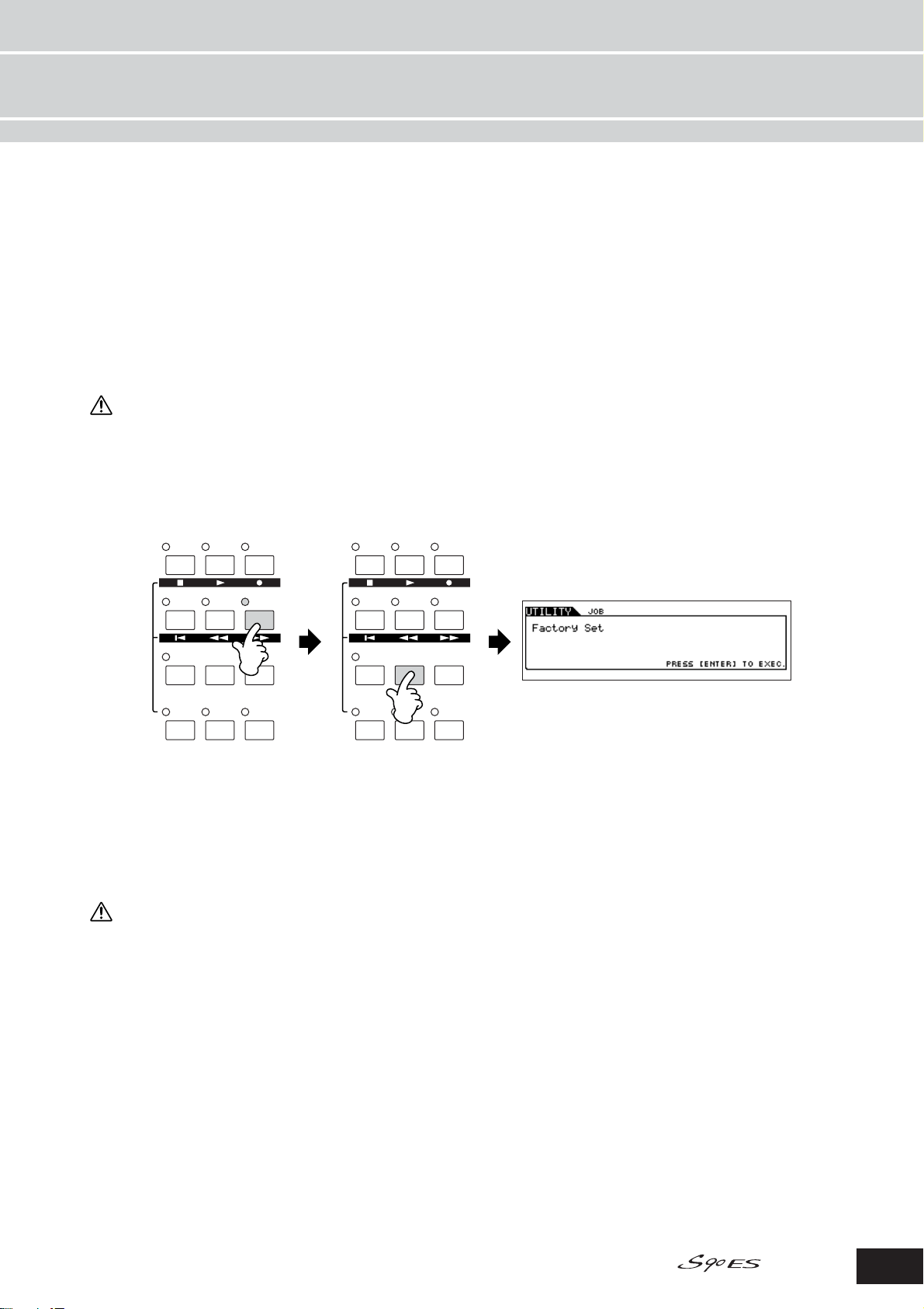
1. Press the [UTILITY] button to enter the Utility mode (the indicator lights).
2. Press the [JOB] button to enter the Utility Job mode.
VOICE
PERFORM
MASTER
VOICE
PERFORM
MASTER
MULTI/
SEQ PLAY
EDIT
COMPARE
REMOTE
FILE UTILITY
JOB STORE
EFFECT
ARPEGGIO
BYPASS
MULTI/
SEQ PLAY
EDIT
COMPARE
REMOTE
FILE UTILITY
JOB STORE
EFFECT
ARPEGGIO
BYPASS
3. Press the [ENTER] button. (The display prompts you for confirmation.)
To return to the original display, press the [DEC/NO] button.
To execute the Factory Set, press the [INC/YES] button.
4. After the Factory Set has been completed, a “Completed” message appears and operation returns to the original
display.
CAUTION
For Factory Set operations that take longer to process, you will see the messa ge “Executing…” or “Please Keep Power On!” during processing. Do not
switch the power off while this message is on the display. Turning the power off in this state results in loss of all user data and may cause the system
to freeze. This means that this synthesizer may not be able to start up properly, even when turning the power on next time.
n All settings in the Utility mode that are related to the Plug-in boards are stored only to the memory on those respective boards, and not to the memory
of this synthesizer. Because of this, the Factory Set operation cannot be used to restore settings for those devices.
Owner’s Manual
21
Page 22
Functions of the MODE buttons
Functions of the MODE buttons
Basic Operation
Mode table
The functions of each mode and how to enter mode are as follows:
Voice mode Play mode Playing a Voice [VOICE]
Performance mode Play mode Playing a Performance [PERFORM]
Multi mode Play mode Playing a Multi [MULTI/SEQ PLAY]
Master mode Play mode Playing a Master [MASTER]
Sequence Play mode Play mode Playing back MIDI files [MULTI/SEQ PLAY]
Job mode Utility mode Setting system related parameters [UTILITY]
File mode File mode Managing files and folders (directories) [FILE]
Enters the mode corresponding to each button.
For details about each mode, see page 12.
Enters each Edit mode when pressing the [EDIT]
button in the Voice, Performance, Multi, or Master
mode. You can edit each program in the Edit
Controls the computer software by using the
buttons and controllers on S90 ES (Page 77).
Mode Function How to enter the mode
Edit mode Editing/Creating a Voice [VOICE] → [EDIT]
Job mode Initializing a Voice, etc. [VOICE] → [JOB]
Store mode Storing a Voice to internal memory [VOICE] → [STORE]
Edit mode Editing/Creating a Performance [PERFORM] → [EDIT]
Job mode Initializing a Performance, etc. [PERFORM] → [JOB]
Store mode Storing a Performance to internal memory [PERFORM] → [STORE]
Edit mode Editing/Creating a Multi [MULTI/SEQ PLAY] → [EDIT]
Job mode Initializing a Multi, etc. [MULTI/SEQ PLAY] → [JOB]
Store mode Storing a Multi to internal memory [MULTI/SEQ PLAY] → [STORE]
Edit mode Editing/Creating a Master [MASTER] → [EDIT]
Job mode Initializing a Master, etc. [MASTER] → [JOB]
Store mode Storing a Master to internal memory [MASTER] → [STORE]
Job mode Restoring factory defaults [UTILITY] → [JOB]
VOICE
MULTI/
SEQ PLAY
PERFORM
MASTER
FILE UTILITY
Enters each Store mode when pressing the
[STORE] button in the Voice, Performance, Multi, or
Master mode, letting you store the edited program
for the relevant mode. In the Utility mode,
pressing the [STORE] button directly executes the
EDIT
COMPARE
REMOTE
JOB STORE
EFFECT
BYPASS
ARPEGGIO
Store operation.
Enters each Job mode when pressing the [JOB]
button in the Voice, Performance, Multi, Master, or
Utility mode. You can initialize and copy data in the
Job mode.
Tur ns the effects and Arpeggio functions on or off (Pages 39, 119).
n Pressing the [MULTI/SEQ PLAY] button toggles between the Multi mode and Sequence Play mode.
■ How to leave the current display
For most operations or displays, pressing the [EXIT] button will let you leave the current display and return you to the
previous one. You can return back to each Play mode by pressing the [EXIT] button several times in the respective mode.
22
DEC/NO
EXIT ENTER
Owner’s Manual
INC/ YES
EXECUTE
Page 23
Functions and Sub-Functions
Functions and Sub-Functions
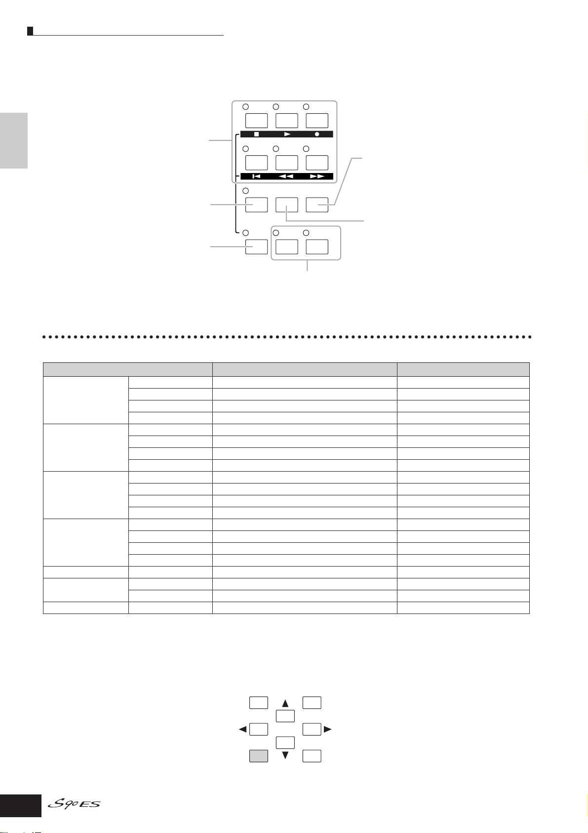
Each mode described above contains various displays, with various functions and parameters. To navigate your way
through these displays and select a desired function, use the [F1] - [F6] buttons and the [SF1] - [SF5] buttons. When you
select a mode, the available displays or menus appear directly above the buttons at the bottom of the display (as shown
below).
Using the Function buttons [F1] - [F6]
These functions can be selected via the
corresponding button ([F1] - [F6]).
SF1F1SF2
F2 F3 F4 F5 F6
SF3 SF4 SF5
INFORMATION
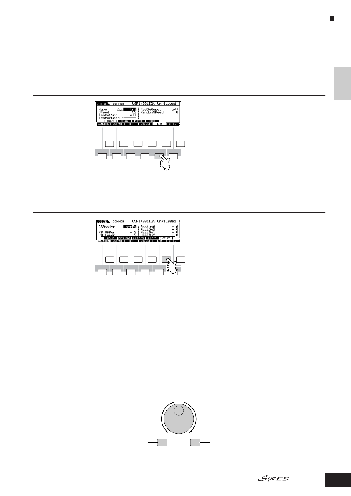
In this example, press the [F5] button to go
to the LFO display.
Depending on the currently selected mode, up to six functions are available and can be called up with the [F1] - [F6]
buttons. Keep in mind that the available functions differ depending on the selected mode.
Using the Sub-Function buttons [SF1] - [SF5]
These functions can be selected via the
corresponding button ([SF1] - [SF5]).
SF1F1SF2
SF3 SF4 SF5
INFORMATION
Basic Operation
F2 F3 F4 F5 F6
In this example, press the [SF5] button
to go to the OTHER display.
Depending on the currently selected mode, up to five functions (sub-functions) are available and can be called up with the
[SF1] - [SF5] buttons. Keep in mind that the available functions differ depending on the selected mode. (Some displays may
not have any sub-functions for these buttons.)
Selecting a Program
In order to play the S90 ES you’ll need to call up one of its programs, i.e., a Voice, Performance, Multi, or Master. These
programs can be selected in each Play mode via the same procedure.
■ Using the [INC/YES], [DEC/NO] buttons and the data dial
The [INC/YES] and [DEC/NO] buttons let you step up or down through the program numbers in any of the Play modes
(Voice, Performance, Multi, and Master).
Rotating the data dial to the right (clockwise) increases the program number, while rotating it to the left (counter-clockwise)
decreases it. This control works in the same way as the [INC/YES] and [DEC/NO] buttons, but lets you scroll through the
programs more quickly.
Decreases number Increases number
Decreases number
DEC/NO INC/YES
Increases number
Owner’s Manual
23
Page 24
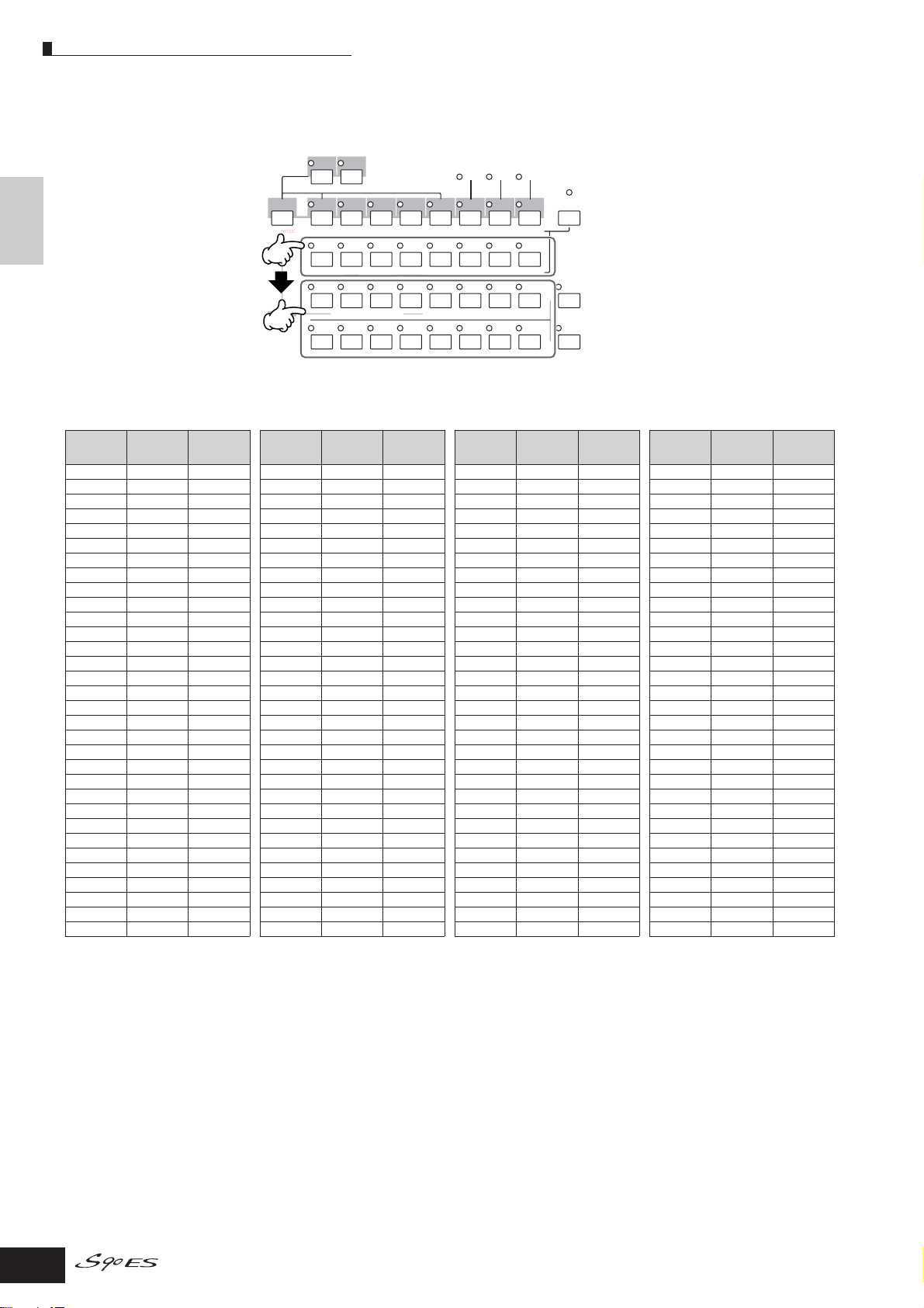
Selecting a Program
■ Using the Group, Number buttons
As shown below, you can select a program number by pressing any of the Group [A] - [H] buttons and pressing any of the
Number [1] - [16] buttons.
Basic Operation
n The convenient Category Search function (page 32) lets you easily locate and select the Voices or Performance you want by type.
The Voice program numbers and the corresponding Group/Numbers are listed below.
DRUM
KITS
FAVORITES
COMMON
USER 1
USER 2
PRE 3
PRE 2
PRE 1
A. PIANO KEYBOA RD ORGAN
A
BCDE FG
SYN PAD/
SYN LEAD
CHOIR
21
ELEMENT/PERF. PART/ZONE
9
10
SYN COMP
3
11
PRE 4
GUITAR/
PLUCKED
CHROMATIC
PERCUSSION
4
12 13
BASS
DRUM/
PERCUSSION
1
SLOT
GM
PLG 1
STRINGS
SE
6
5
14
SLOT 2
PLG 2
BRASS
MUSICAL FX
7
15
SLOT 3
PLG 3
REED/PIPE
H
COMBI
8
16
CATEGORY
SEARCH
TRACK
SELECT
MUTE
SOLO
Program
Number
Group Number
Program
Number
Group Number
Program
Number
Group Number
Program
Number
Group Number
001 A 1 033 C 1 065 E 1 097 G 1
002 A 2
003 A 3
004 A 4
005 A 5
006 A 6
007 A 7
008 A 8
009 A 9
010 A 10
011 A 11
012 A 12
013 A 13
014 A 14
015 A 15
016 A 16
017 B 1
018 B 2
019 B 3
020 B 4
021 B 5
022 B 6
023 B 7
024 B 8
025 B 9
026 B 10
027 B 11
028 B 12
029 B 13
030 B 14
031 B 15
032 B 16
034 C 2 066 E 2 098 G 2
035 C 3 067 E 3 099 G 3
036 C 4 068 E 4 100 G 4
037 C 5 069 E 5 101 G 5
038 C 6 070 E 6 102 G 6
039 C 7 071 E 7 103 G 7
040 C 8 072 E 8 104 G 8
041 C 9 073 E 9 105 G 9
042 C 10 074 E 10 106 G 10
043 C 11 075 E 11 107 G 11
044 C 12 076 E 12 108 G 12
045 C 13 077 E 13 109 G 13
046 C 14 078 E 14 110 G 14
047 C 15 079 E 15 111 G 15
048 C 16 080 E 16 112 G 16
049 D 1 081 F 1 113 H 1
050 D 2 082 F 2 114 H 2
051 D 3 083 F 3 115 H 3
052 D 4 084 F 4 116 H 4
053 D 5 085 F 5 117 H 5
054 D 6 086 F 6 118 H 6
055 D 7 087 F 7 119 H 7
056 D 8 088 F 8 120 H 8
057 D 9 089 F 9 121 H 9
058 D 10 090 F 10 122 H 10
059 D 11 091 F 11 123 H 11
060 D 12 092 F 12 124 H 12
061 D 13 093 F 13 125 H 13
062 D 14 094 F 14 126 H 14
063 D 15 095 F 15 127 H 15
064 D 16 096 F 16 128 H 16
n When selecting a Voice, it is necessary to press one of the Bank buttons before pressing the Group and Number buttons.
n The amount of numbers differ depending on the program. For example, while the selected number range of the Normal Voice, Performance, and
Master is 001 - 128, the selected number range of the Multi is 001 - 064.
24
Owner’s Manual
Page 25
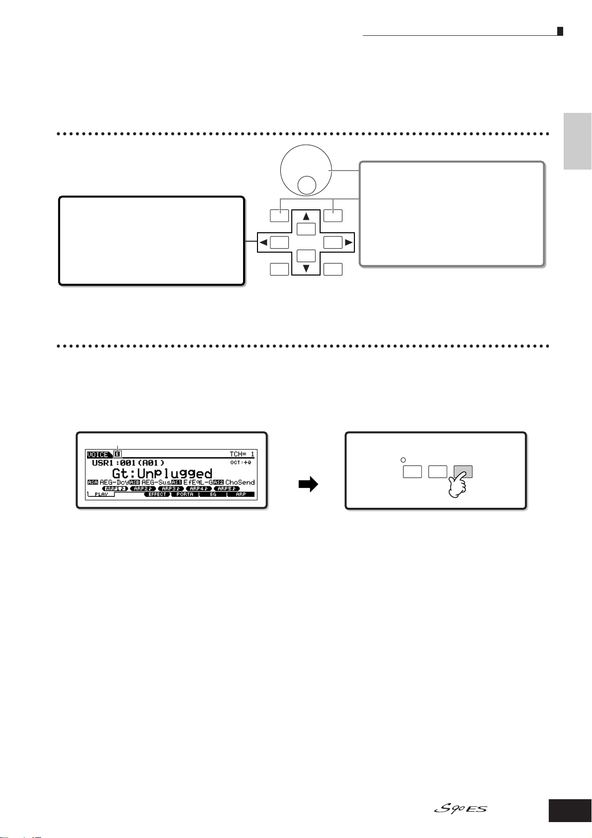
About the editing functions
In this section, we’ll explain the basic operations for editing the Voice, Performance, Multi settings.
Moving the Cursor and Setting Parameters
About the editing functions
Changing (editing) parameter values
Rotating the data dial to the right (clockwise) increases
the value, while rotating it to the left (counter-clockwise)
Moving the cursor
Use these four buttons to navigate the display, moving
the cursor around the various selectable items and
parameters in the screen. When selected, the relevant
item is highlighted (the cursor appears as a dark block
with inverse characters). You can change the value of
the item (parameter) at which the cursor is located by
using the data dial, [INC/YES] and [DEC/NO] buttons.
DEC/NO
EXIT ENTER
INC/ YES
EXECUTE
decreases it.
For parameters with large value ranges, you can
increase the value by 10 by simultaneously holding
down the [INC/YES] button and pressing the [DEC/NO]
button. To decrease by 10, do the opposite;
simultaneously hold down the [DEC/NO] button and
press the [INC/YES] button.
Edit Indicator
You can adjust or set various parameters by using the data dial, [INC/YES] button, [DEC/NO] button, and Control sliders in
each mode.
When changing the value of the parameter in the Voice, Performance, and Multi modes, the [E] (Edit Indicator) will appear
on the top left corner of the LCD display. This indicates that the current program (Voice, Performance, or Multi) has been
modified but not yet stored. If you wish to store your sound obtained by edit operation, be sure to store the current program
to internal memory in the Store mode before selecting another program (pages 50, 56, 76).
Edit Indicator
Basic Operation
If the Edit Indicator
appears...
EDIT
COMPARE
JOB STORE
Owner’s Manual
25
Page 26
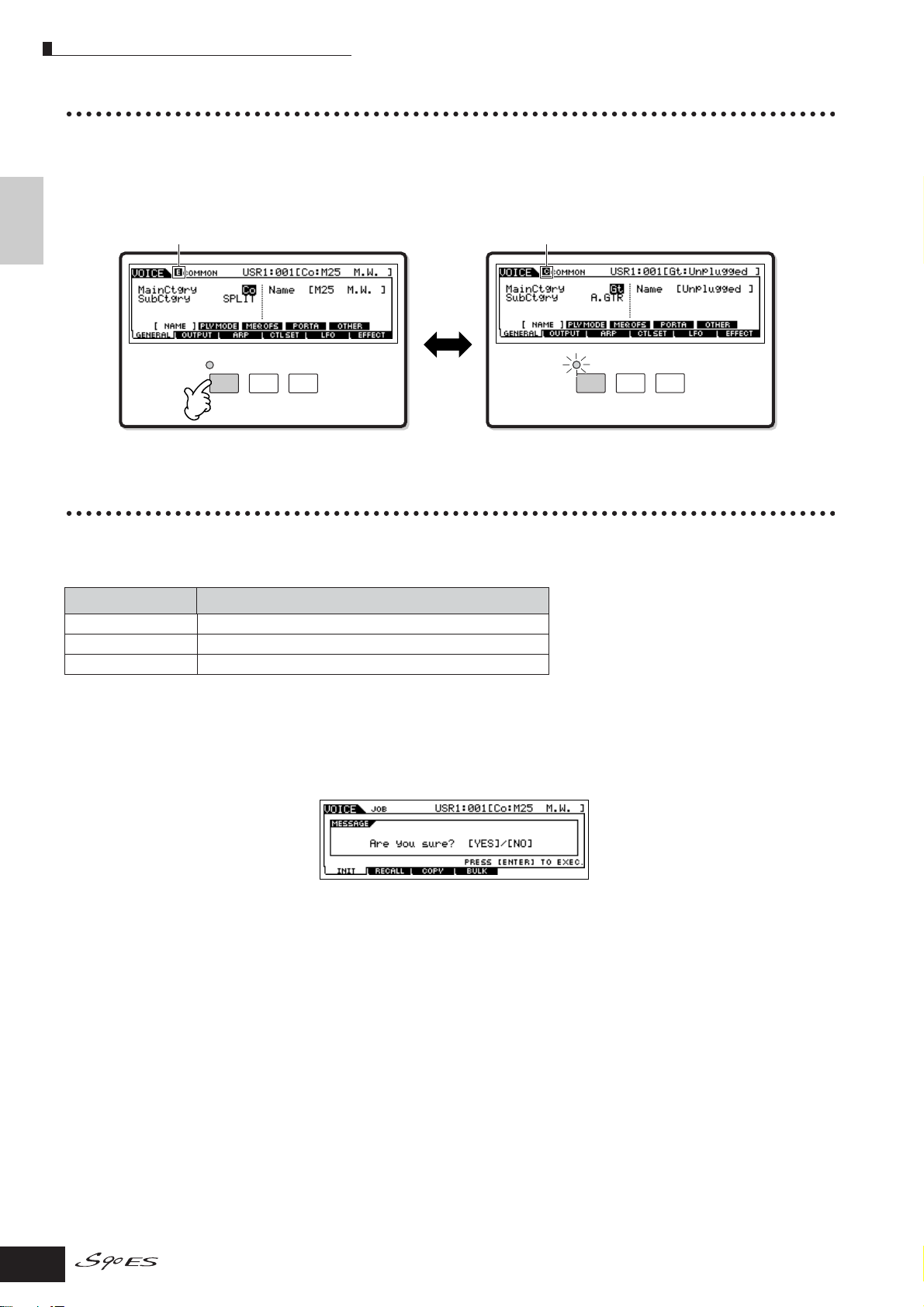
Confirmation Message
Compare Function
This convenient function lets you switch between the edited sound and its original, unedited condition—allowing you to
listen to the difference between the two and better hear how your edits affect the sound.
Basic Operation
For example, when editing a Voice in the Voice Edit mode, the “E” Edit indicator is shown. Pressing the [EDIT] button in this
condition reverts to the original unedited sound (the button lamp flashes and the “C” Compare indicator is shown). Press the
[EDIT] button again to return to the edited sound (page 104).
Edit Indicator (newly edited sound) Changes to the Compare Indicator (original sound)
EDIT
EDIT
JOB STORE
JOB STORE
COMPARE
COMPARE
Edit Recall Function
If you are editing a program and select a different program without storing your edited one, all the edits you’ve made will be
erased. However, the edited program is maintained in a backup memory location for the Edit Recall function. To restore the
lost data with your latest edits intact, use the Edit Recall function in the Job mode (page 104).
Job mode How to call up the Edit Recall display
Voice [VOICE] → [JOB] → [F2] RECALL
Performance [PERFORM] → [JOB] → [F2] RECALL
Multi [MULTI/SEQ PLAY] → [JOB] → [F2] RECALL
Confirmation Message
When you execute certain operations, such as those in the Job, Store, and File modes, a confirmation message appears.
This lets you actually execute the operation or cancel it if desired. If a confirmation message (like the one illustrated above)
appears, press the [INC/YES] button to execute the operation or press the [DEC/NO] button to cancel it.
26
Owner’s Manual
Page 27
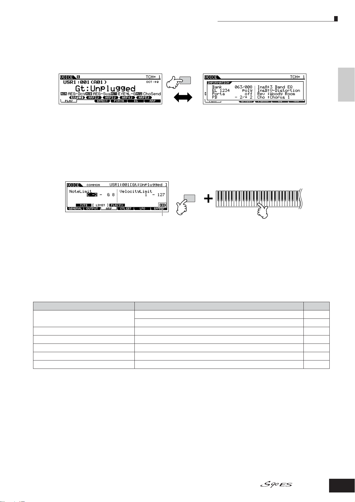
Information Display
Information Display
This convenient function lets you call up relevant details about the selected mode—simply by pressing the [INFORMATION]
button. For example, when the Voice mode is active, you can quickly check information about which voice bank is selected,
what Play mode (poly or mono) is being used, which effects are applied, and so on.
INFORMATION
For details, see page 176.
Note (Key) settings
Several parameters let you set a key range for a function—for example, in setting up a keyboard split—by specifying certain
note values. You can use the [INC/YES] and [DEC/NO] buttons or data dial to set these parameters, or you can directly enter
the values from the keyboard by pressing the appropriate keys (as shown below).
Basic Operation
INFORMATION
When Note Limit is selected, the [KBD] mark appears,
indicating that you can use the keyboard to set the
value. Simultaneously hold down the [INFORMATION]
button and press the appropriate key.
n About the note name assigned to each key, see page 16.
Naming
You can freely name data you’ve created, such as voices and files saved to the USB storage device. The chart below lists
the types of data that can be named along with the operations for calling up the respective naming displays.
Data types that can be named How to call up the naming display Page
Voice [VOICE] → [EDIT] → [F1] GENERAL → [SF1] NAME 128
[MULTI/SEQ PLAY] → [F3] VOICE → Normal Voice Selection → [F5] VCE ED 161
Performance [PERFORM] → [EDIT] → [F1] GENERAL → [SF1] NAME 150
Multi [MULTI/SEQ PLAY] → [EDIT] → [F1] GENERAL → [SF1] NAME 158
Master [MASTER] → [EDIT] → [F1] NAME 173
Volume Label of the USB storage device [FILE] → [F1] CONFIG → [SF3] FORMAT 168
File/Folder saved to the USB storage device [FILE] → [F2] SAVE or [F4] RENAME 168
First, call up the name input display according to the above table, then, move the cursor by using the Cursor button to the
desired location and input a character. See below for details.
n Since the name of the program is part of the data, make sure that you properly save the program after naming it.
Owner’s Manual
27
Page 28
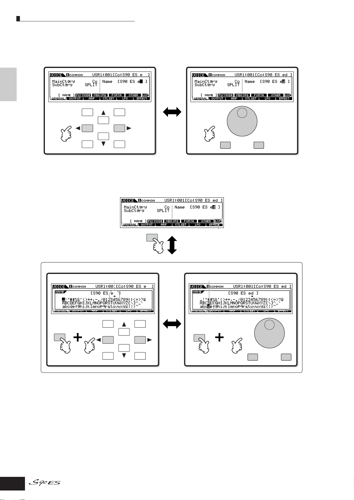
Naming
■ Basic naming operation
As shown below, you can set the name by repeating the two operations—moving the cursor to the desired location by using
the Cursor button and selecting a character by using the data dial, [INC/YES] button, and [DEC/NO] button.
Basic Operation
Moving the cursor to the desired location on the name Selecting a character at the cursor location
DEC/NO
EXIT ENTER
INC/ YES
DEC/NO INC/YES
EXECUTE
■ Using the character list
If you find it difficult to select the desired characters with the above method, you may want to use the following method —
selecting the characters from a list.
INFORMATION
Perform the operations below while holding the [INFORMATION] button.
When the cursor is located at the Name, this [LIST] icon
appears and you can call up the Character List display by
holding the [INFORMATION] button. Release the
[INFORMATION] button to return back to the original display.
INFORMATION
Move the cursor to the desired location.
DEC/NO
EXIT ENTER
INC/ YES
EXECUTE
Select a character for the cursor location on the name.
INFORMATION
DEC/NO INC/YES
28
Owner’s Manual
Page 29
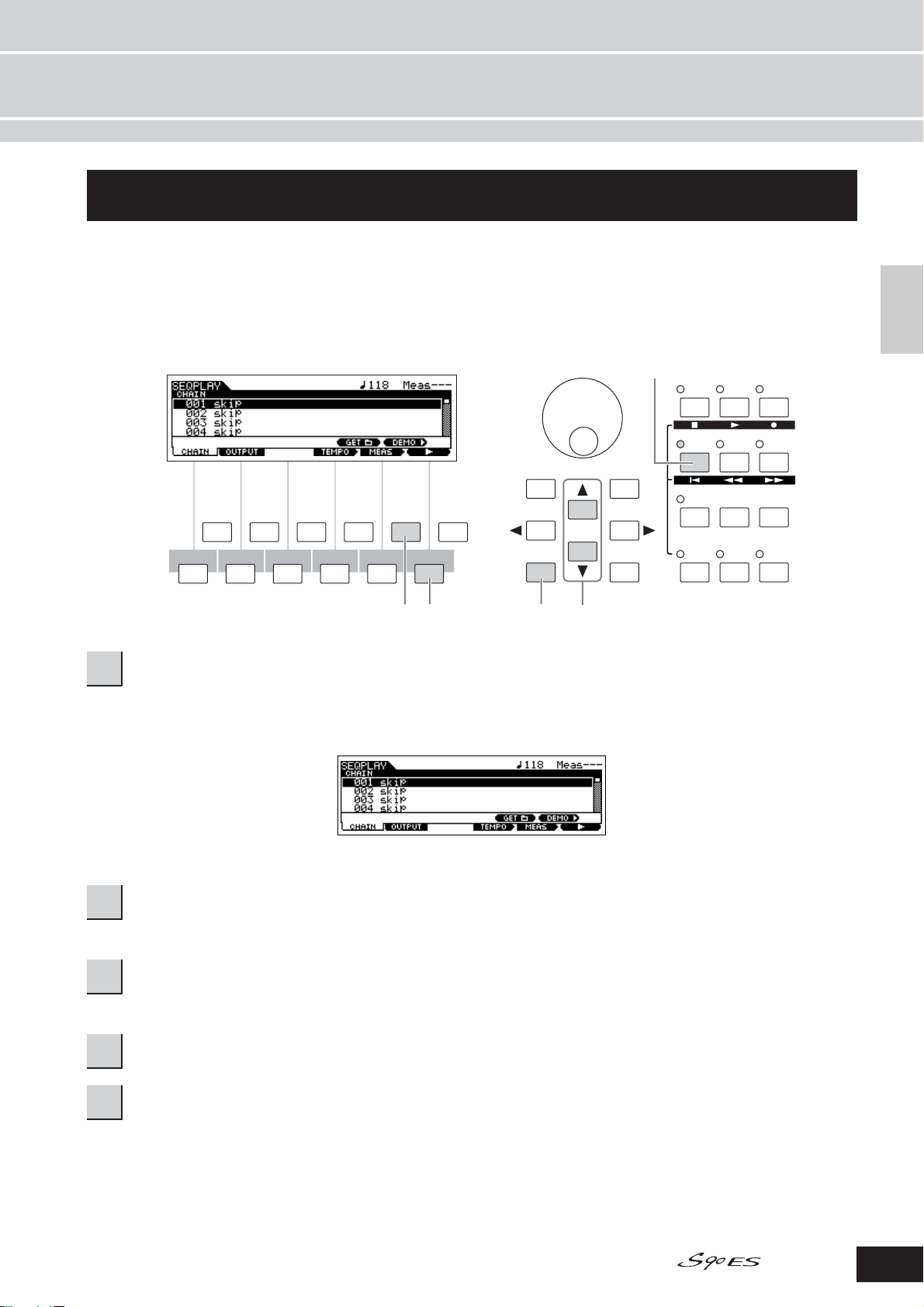
Playing the Demo Songs
Quick Guide
Playing the Demo Songs
Several demo songs are included with this synthesizer. In this section, you’ll learn how to play them back.
n Make sure the synthesizer is ready for playback. Details are given in the section “Setting up and Playing” on page 8.
1
PERFORM
VOICE
MULTI/
FILE UTILITY
SEQ PLAY
SF1
F1
SF2
SF3 SF4 SF5
F2 F3 F4 F5 F6
DEC/NO
INFORMATION
EXIT ENTER
INC/ YES
EDIT
COMPARE
REMOTE
JOB STORE
EFFECT
BYPASS
Quick GuidePlaying the Demo Songs
MASTER
ARPEGGIO
EXECUTE
223,4
Press the [MULTI/SEQ PLAY] button to enter the Sequence Play mode.
1
5
If the following display does not appear, press the [MULTI/SEQ PLAY] button again.
Press the [SF5] DEMO button to call up the Demo songs.
2
n You can select the first song for playback by using the [▲][▼] buttons.
Press the [F6]Fbutton to start playback of the Demo song.
3
n You can also specify the song tempo or the song position. The operation is the same as in the Sequence Play mode (page 96).
The [SF6]Jbutton lets you pause playback and then start again from the same point in the song.
4
To exit from the Demo display, stop playback, then press the [EXIT] button.
5
Demo song playback continues indefinitely until stopped.
Owner’s Manual
29
Page 30
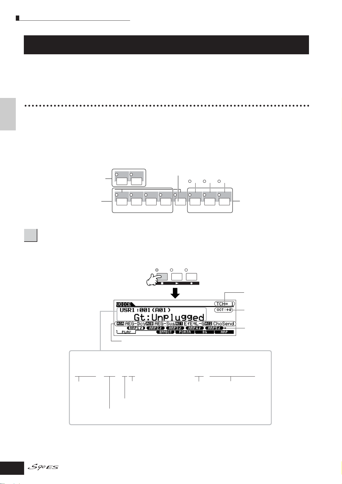
Voice Play mode
Playing the S90 ES
Voice Play mode
The Voice Play mode is where you select and play the instrument sounds (voices) of this synthesizer.
Quick Guide Playing the S90 ES
Selecting a Normal Voice
Internally, there are two Voice Types: Normal Voices and Drum Voices. Normal Voices are mainly pitched musical instrumenttype sounds that can be played over the range of the keyboard. Drum Voices are mainly percussion/drum sounds that are
assigned to individual notes on the keyboard. In this section, we’ll show you how to select a Normal Voice.
You can select the desired Voice from various Voice Banks (Preset 1 - 4, User 1 - 2, GM preset, Plug-in 1 - 3) as shown
below.
Voice Bank
1
In this condition, playing the keyboard sounds the Voice indicated in the display.
The parameters shown in the Voice Play mode are briefly explained below.
GM Preset Bank
Contains the voices allocated according to the
User Bank
Contains the voices you’ve
USER 1
USER 2
GM standard. For details, see page 112.
created in the Voice Edit mode.
Preset Bank
Contains the Voices
PRE 1
PRE 2
PRE 3
PRE 4
built into this
instrument.
A. PIANO KEYBOARD ORGAN
GUITAR/
PLUCKED
BASS
Press the [VOICE] button to enter the Voice Play mode.
SLOT
1
GM
PLG 1
SLOT 2
PLG 2
SLOT 3
PLG 3
Plug-in Bank
Available when Plug-in Boards have
STRINGS
BRASS
REED/PIPE
been installed. See page 99.
MASTER
PERFORM
VOICE
Indicates the Keyboard MIDI
transmit channel. See page 105
for details.
Indicates the Keyboard Octave
setting. See page 105 for details.
ARP1-ARP5
Use the [SF1] - [SF5] buttons
Indicates the functions assigned to the respective Control
sliders. See page 47.
to call up the Arpeggio type
assigned to each button (page
39).
Indicates the currently selected voice.
Bank and Voice Program number
Category and Voice name
USR1 : 001 (A01) Gt : Unplugged
Bank
(selected via the
buttons)
Number
(selected via the Number
[1] - [16] buttons)
Group
(selected via the Group [A] - [H] buttons)
Voice Program number
(corresponding to Groups A to H and Numbers 01 to 16)
n Keep in mind that the example displays shown in this manual are for instruction purposes only, and the contents (for example, the Voice name here)
may differ slightly from those on your instrument.
Category Voice name
30
Owner’s Manual
Page 31

Voice Play mode
SYN LEAD
A
BCDEF G
H
SYN PAD/
CHOIR
SYN COMP
CHROMATIC
PERCUSSION
DRUM/
PERCUSSION
SE
MUSICAL FX
COMBI
ELEMENT/PERF. PART/ZONE
8
7
6
5
4
3
21
16
15
14
12 13
11
10
9
Select a Normal Voice Bank.
2
Select one of the Banks from Preset 1 - 4, User 1 - 2, and
GM.
USER 2
USER 1
PRE 4
GUITAR/
PLUCKED
BASS
GM
PLG 1
PLG 2
PLG 3
STRINGS
BRASS
REED/PIPE
Voice
PRE 3
PRE 2
PRE 1
A. PIANO KEYBOARD ORGAN
Group
About the User Banks
The User Banks contain various factory default Voices.
User Bank 1 (USR1): This Bank contain original Voices for
the User Bank. The same Voices are not included in the
Preset Banks.
User Bank 2 (USR2): This Bank contains recommended
Voices copied from the Preset Banks.
If a Voice in a User Bank (User Voice) is overwritten or
replaced, that User Voice will be lost. When you save an
edited Voice, be careful not to overwrite any important User
Voices.
Select a Normal Voice Group.
3
Voices in each Bank are divided into Groups [A] - [H].
Select a Group to display the Voices that belong to the
selected Group.
Select a Normal Voice Number.
4
Press one of the Number [1] - [16] buttons.
Quick Guide Playing the S90 ES
Play the keyboard.
5
Owner’s Manual
31
Page 32

Voice Play mode
Selecting a Drum Voice
1
2
While holding the [DRUM KITS] button, press one of the
Quick Guide Playing the S90 ES
following buttons: [PRE 1] (Preset Drum), [USER 1] (User
Drum), or [GM] (GM Drum).
3
This operation is basically the same as in selecting a
Normal Voice. The numbers of Groups that you can select
depends on the Bank you’ve selected in step 2.
Press the [VOICE] button to enter the Voice
Play mode.
Select a Drum Voice Bank.
USER 1
USER 2
DRUM
KITS
FAVORITES
PRE 3
PRE 2
PRE 1
A. PIANO KEYBOARD ORGAN
PRE 4
GUITAR/
PLUCKED
GM
BASS
Select a Drum Voice Group.
Select a Drum Voice Number.
4
This is the same as in selecting a Normal Voice.
Play the keyboard and check which
5
instrument is assigned to each key.
n For details about the instrument assignments for each key, refer to
the separate Data List.
Using the [INC/YES], [DEC/NO] buttons and
data dial
In steps 3 and 4 above, you can select a Voice
Number by using the [INC/YES], [DEC/NO] buttons
and data dial.
Decreases number Increases number
DEC/NO INC/YES
Decreases number
Increases number
Using the Category Search function
You’ll probably have a lot of fun and inspiration going through the Voices one-by-one, listening to each in order—but it will
take you a long time to get through all of them, since the S90 ES has so many. This is where the Category Search function
comes in handy. It’s a powerful and easy-to-use way to quickly find the Voices you want. Let’s try out the feature below,
searching for a Voice in the Pipe Organ category.
Turn the Category Search function on by
1
pressing the [CATEGORY SEARCH] button.
n Press the [CATEGORY SEARCH] button again to turn this function
off.
PRE 3
PRE 2
PRE 1
A. PIANO KEYBOARD ORGAN
A
BCDEF G
SYN PAD/
CHOIR
SYN COMP
SYN LEAD
PRE 4
GUITAR/
PLUCKED
CHROMATIC
PERCUSSION
GM
BASS
DRUM/
PERCUSSION
PLG 1
STRINGS
SE
PLG 2
BRASS
MUSICAL FX
PLG 3
REED/PIPE
H
COMBI
CATEGORY
SEARCH
Select the Organ Category.
2
Press the [PRE 3] ORGAN button of the Bank buttons and
Group buttons. The Voices in the Organ Category are
displayed in a list.
PRE 4
GUITAR/
PLUCKED
GM
BASS
DRUM/
PERCUSSION
PRE 3
PRE 2
PRE 1
A. PIANO KEYBOARD ORGAN
A
BCDEF G
SYN PAD/
SYN COMP
SYN LEAD
CHOIR
CHROMATIC
PERCUSSION
PLG 1
STRINGS
SE
Voice ListCategory
PLG 2
BRASS
MUSICAL FX
CATEGORY
PLG 3
SEARCH
REED/PIPE
H
COMBI
Category names
32
Sub Category
Owner’s Manual
Page 33

Voice Play mode
SF1F1SF2
F2 F3 F4 F5 F6
SF3 SF4 SF5
INFORMATION
Checkmark on
Checkmark off
Pressing [F5]
toggles between
the two settings:
To r emove all the marked Voices from the Favorite
Category, simply press the [F6] CLR ALL button.
FAVORITES
DRUM
KITS
Select the Sub Category of pipe organ.
3
The Sub Category names are shown at the bottom of the
Category Search display. All Categories are divided into
two or three Sub Categories for further ease in selection.
Here, press the [F2] PIPE button.
SF 1SF 2SF 3
SF 1SF 2SF 3
F1 F2 F3
F1 F2 F3
n An alternate way of selecting categories is to use the Cursor
buttons to select and highlight the Category name in the display,
then use the [INC/YES] and [DEC/NO] buttons or the data dial to
select the Category.
n Some Voices such as User Voices may not be registered to any
Category. You can search for these Voices by setting the Category
to “--------.”
Select the desired Voice from the Voice list of
4
pipe organ.
Step through the available Voices by using the data dial.
You can also use the [INC/YES] and [DEC/NO] buttons, or
use the Cursor [▲][▼] buttons.
Register the Voice selected in step 1 to the
Favorite Category by pressing the [F5] SET/
2
CLR button, checkmarking the box next to the
Voice name.
You can un-checkmark the selection by pressing the [F5]
button again.
Press the [FAVORITES] button to see the
Voices you’ve set to the Favorite Category in
3
step 2.
You also can use the [F5] SET/CLR and [F6] CLR ALL
buttons in this display to register/remove the voices to/from
the Favorite Category.
Quick Guide Playing the S90 ES
DEC/NO
EXIT ENTER
Press the [ENTER] button to actually select
5
the Voice.
n You can also use the [CATEGORY SEARCH] button and [EXIT]
button to select the Voice.
INC/ YES
EXECUTE
Favorite Category
The S90 ES also lets you collect and store your favorite
Voices to create your personal “Favorite” Category. By
putting your most often-used Voices in the Favorite
Category, you can select your favorite Voices quickly and
easily.
Select the Voice using the Category Search
1
function.
Press the [FAVORITES] button again to return
4
to the Category Search display.
Pressing the [CATEGORY SEARCH] button to
exit from the Category Search display will
5
store the Favorite Category settings to
internal memory automatically.
CAUTION
The settings made in steps 2 - 3 will be lost if you turn the power off
without executing step 5.
step 5.
CAUTION
Never attempt to turn off the power while an “Executing...” or “Please
keep power on” message is shown. Turning the power off in this state
may cause the system to freeze and prevent normal startup the next
time the power is turned on, as well as resulting in the loss of all user
data.
Owner’s Manual
33
Page 34

Performance Play mode
Performance Play mode
Each Performance can contain up to four different Parts. This lets you play, for example, Flute, Violin, and Timpani Voices in
a layer across the keyboard, or split the keyboard according to the bass and melody parts, then play the two different
instruments and sound like a duo—even though you’re playing by yourself.
Selecting a Performance
128 Performances (1 bank) are provided in internal User memory. In the Performance Play mode, you can select and play
Quick Guide Playing the S90 ES
individual User Performances.
Since there is only one bank for Performances, you need not select a Performance Bank.
1
In this condition, playing the keyboard sounds the Performance indicated in the display. The parameters shown in the
Performance Play mode are briefly explained below.
Press the [PERFORM] button to enter the Performance Play mode.
PERFORM
VOICE
MASTER
Indicates the Keyboard MIDI
transmit channel. See page 105
for details.
Indicates the Keyboard Octave
setting. See page 105 for details.
ARP1-ARP5
Use the [SF1] - [SF5] buttons to call
up the Arpeggio type assigned to
Indicates the functions assigned to the respective Control
sliders. See page 42.
Indicates the currently selected Performance.
Bank and Performance Program number
Category and Performance name
each button (page 39).
USER : 001 (A01) Co : Wide River
Number
(selected via the Number
[1] - [16] buttons)
Group
(selected via the Group [A] - [H] buttons)
Performance Program number
(corresponding to Groups A to H and Numbers 01 to 16)
n Keep in mind that the example displays shown in this manual are for instruction purposes only, and the contents (for example, the Performance name
here) may differ slightly from those on your instrument.
Category Performance nameBank
34
Owner’s Manual
Page 35

Performance Play mode
DEC/NO INC/YES
Increases number
Decreases number Increases number
Decreases number
Select a Performance Group.
2
Performances are divided into Groups [A] - [H]. Select a
Group to display a list of the Performances.
A
BCDEF G
SYN PAD/
SYN COMP
SYN LEAD
CHOIR
Select a Performance Group.
3
CHROMATIC
PERCUSSION
Group Performance
DRUM/
PERCUSSION
MUSICAL FX
SE
H
COMBI
Press one of the Number [1] - [16] buttons.
3
21
4
6
5
8
7
Play the keyboard.
4
Using the [INC/YES], [DEC/NO] buttons and
data dial
Rather than using the Bank/Number buttons
described in steps 2 and 3 above, you can select a
Performance by using the [INC/YES], [DEC/NO]
buttons and data dial.
Quick Guide Playing the S90 ES
ELEMENT/PERF. PART/ZONE
9
10
11
12 13
14
16
15
Using the Category Search function
As in the Voice Play mode, you can use the Category
Search and Favorite Category functions in the Performance
Play mode.
For details on how to use the function, see page 32.
Owner’s Manual
35
Page 36

Performance Play mode
Creating a Performance by combining the Voices
Performances can be made up of a maximum of four Parts, each of which can be assigned a different Voice. In this section,
we’ll create a Performance by combining two Voices.
Preparing to create the Performance
(Initializing the Performance)
Quick Guide Playing the S90 ES
1
2
The Initialize display is shown. Check the “ALL” check box
to initialize all data of the Performance. For details about
the Initialize function, refer to page 156.
Select the desired Performance in the
Performance Play mode.
Press the [JOB] button, and then the [F1]
button.
EDIT
JOB STORE
COMPARE
SF1F1SF2
F2 F3 F4 F5 F6
SF3 SF4 SF5
INFORMATION
Playing the several Voices together
(Layer)
Press the [F2] VOICE buttom.
5
This calls up a list indicating which Voice is assigned to
each Part of the current Performance.
Since the current Performance has been initialized, the
only Voice in the Performance is “PRE1:
Natural S,” set to Part 1.
SF1F1SF2
F2 F3 F4 F5 F6
Assign the desired Voice to Part 2.
6
SF3 SF4 SF5
INFORMATION
6-1 Move the cursor to the Voice Bank or Voice
Number of the Part 2.
Voice Bank
Voice Number
Press the [ENTER] button. (The display
3
prompts you for confirmation.)
Press the [INC/YES] button to initialize the Performance.
n Please note that when you execute the Store operation by pressing
the [STORE] button here, the Performance at the destination will be
replaced with the Initialized Performance created in step 3 above.
n For details about the Store operation, refer to page 56.
Press the [PERFORM] button.
4
The current Performance name will change to “Init Perf” in
the display.
n When you initialize a Performance, the Voice at Preset Bank 1,
Voice number 1 is assigned to Part 1 as the default.
6-2 Press the [SF1] ADD INT button. This enables
assignment of the selected internal Voice to Part
2.
n When assigning a Voice from Single-part Plug-in Board (page 99)
to a Part, press the [SF2] ADD PLG button.
36
Owner’s Manual
Page 37

Performance Play mode
SF 4 SF 5
Note Limit Low Note Limit High
Part 1: Piano Part 2: Flute
6-3 Select the Voice you’ve assigned to Part 2 as you
did in steps 2 - 4 in the section “Selecting a
Normal Voice” or “Selecting a Drum Voice” (page
30).
You can select the desired Bank and Number directly by
using the [DEC/NO], [INC/YES] buttons and data dial. You
can also use the Category Search function (page 32). Here,
we’ll assign a flute Voice (PRE3: C Flute) to Part 2.
Voice Bank
SF1F1SF2
Assigns an internal Voice
to the selected Part. Part.
Assigns a Plug-in Voice to the selected Part.
(Available when a Plug-in Board has been installed.)
n Voices of the Multi part Plug-in Board PLG100-XG cannot be
assigned to Performance Parts; they are specifically meant to be
used in the Multi mode for playback of XG song data.
Voice Number
SF3 SF4 SF5
F2 F3 F4 F5 F6
Deletes the Voice assignment of
the selected Part.
INFORMATION
Assign the Voice of Part 2 to the higher key
9
range.
9-1 Move the cursor to Part 2.
9-2 Press a note on the keyboard while holding the
[SF4] LIMIT L button down to set the lowest note
of Part 2.
n Note that the dark bar (at “NOTE”) for Part 2 changes as the note
range is changed.
Play the keyboard.
10
Quick Guide Playing the S90 ES
Play the keyboard.
7
The Part 1 (piano Voice) and Part 2 (flute Voice) can be
played in unison.
Part 1: Piano
Part 2: Flute
Next, we'll divide the keyboard into two sections for each
Voice.
Dividing the keyboard into separate
sections— Split
Assign the Voice of Part 1 to the lower key
8
range.
8-1 Move the cursor to Part 1.
8-2 Press a note on the keyboard while holding down
the [SF5] LIMIT H button to set the highest note
for Part 1.
n Note that the dark bar (at “NOTE”) for Part 1 changes as the note
range is changed.
Use your left hand to play piano sounds and your right
hand to play flute sounds.
Adjusting the Part levels and storing
the Performance
Adjust the Volume settings of Parts 1 and 2 by
11
using the Control sliders.
For details, see page 42.
Store the settings as a User Performance in
12
the Performance Store mode.
For details about the Store operation, see page 56.
n If you are editing a program and you select a different program
without storing your edited one, all the edits you’ve made will be
erased.
In the section above, you learned how to assign two Voices
to two different Parts. Use same procedure to assign
Voices to Parts 3 and 4, and create a full orchestral sound
or the sound of a 3- or 4-piece band—just by using a single
S90 ES. You can also use the preset Performances as
starting points in building your own custom Voice
combinations.
Owner’s Manual
37
Page 38

Performance Play mode
Using a microphone and other audio device sounds
One of the enormous benefits of the Performance mode is that you can have the A/D input sound—such as your voice
through a microphone, a guitar, bass, or CD player—assigned as one of the four Parts of a Performance. Various parameters
such as volume, pan, and effect can be set to this Part and the sound is output together with other Parts. These parameters
are set and stored in the Performance Store mode for each Performance.
n The Audio Input part is available also in the Multi mode, but is not available in the Voice mode. The procedure and explanations here apply to the Multi
Quick Guide Playing the S90 ES
1
2
mode as well.
Make sure to turn the power of the S90 ES off
and set the GAIN knob on the rear panel to the
minimum.
Plug the external device to the A/D INPUT
jack(s) on the rear panel.
monaural stereo
A/D INPUT
GAIN
A/D INPUT
GAIN
Set the Mic/Line parameter.
6
When the output level of the connected equipment (such
as a microphone, guitar, bass) is low, set this parameter to
“mic.” When the output level of the connected equipment
(such as a synthesizer keyboard, CD player) is high, set
this parameter to “line.”
LR
n A standard dynamic microphone is recommended. (The S90 ES
does not support phantom-powered condenser microphones.)
Turn on the power of the external device, and
3
then turn on the power of the S90 ES.
LR
Press the [PERFORM] button to enter the
Performance Play mode and select the desired
4
Performance.
Press the [UTILITY] button to enter the Utility
mode, press the [F2] I/O button, then press the
5
[SF1] INPUT button.
MULTI/
FILE UTILITY
SEQ PLAY
n This setting is available for all modes. If you wish to store this
setting, press the [STORE] button.
Adjust the external device input level by using
the GAIN knob on the rear panel while
7
listening to the sound of the external device.
n If you are using the mLAN input Part, the GAIN knob has no effect
on the input level.
A/D INPUT
GAIN
LR
Set the audio input related parameters as
necessary from the AUDIO IN display
8
([PERFORM]
→ [EDIT] → [COMMON] → [F5]
AUDIO IN).
38
SF1F1SF2
F2 F3 F4 F5 F6
Owner’s Manual
SF3 SF4 SF5
INFORMATION
For details about each parameter, see page 151 in the
Reference section.
When the optional mLAN16E has been installed, call up the A/D
display by pressing the [SF5] button.
Store the settings as a User Performance in
9
the Performance Store mode (page 56).
Page 39

Using the Arpeggio feature
SF 1SF 2SF 3SF 4SF 5
Arpeggio type currently selected.
Using the Arpeggio feature
The versatile Arpeggio feature allows you to automatically play various rhythms and phrases by simply pressing a key or
playing a chord. The S90 ES contains a remarkably wide variety of Arpeggios—a total of 1,787—from
conventional, popular phrases to the latest cutting-edge rhythm patterns. In addition, you can assign your favorite
Arpeggios to the [SF1] - [SF5] buttons and switch between Arpeggio phrases instantly. This powerful function is an
unending source of inspiration and will help you create various riffs, phrases and songs quickly and easily.
Since the preset Voices and Performances already have their own Arpeggio types pre-assigned, all you need to do is select
the desired Voice and turn on the Arpeggio function.
n For details about Arpeggio, see page 124.
n Different Arpeggio types cannot be played back for each Part in the Performance or Multi mode.
Press the [ARPEGGIO] button to turn
1
Arpeggio on.
Selecting some programs (Voices, Performances, Multis)
automatically turns this lamp on.
EFFECT
BYPASS
ARPEGGIO
REMOTE
Play a note or notes on the keyboard to trigger
2
the Arpeggio playback.
The particular rhythm pattern or phrase that plays depends
on the actual notes or chords you play, as well as on the
selected Arpeggio type. For details, see page 124 in the
Basic Structure section.
■ Changing the Arpeggio type during your
keyboard performance
A different Arpeggio type is assigned to each of the [SF1]
ARP1 - [SF5] ARP5 buttons for each preset Voice. When a
musical note icon appears to the right of each Arpeggio
number in the display (see below), the corresponding
button is assigned an Arpeggio type. The selected
Arpeggio type is highlighted. Try out various Arpeggio
types by pressing the [SF1] - [SF5] buttons.
You can confirm the currently selected Arpeggio type in the
[F6] ARP display.
Quick Guide Playing the S90 ES
Bank Selects “pre” (Preset) or “usr” (User). To play Arpeggios of
the “usr” bank, User Arpeggio data of the MOTIF ES must
be loaded to the S90 ES.
Ctgr For details, refer to page 124.
Type Refer to the separate Data List booklet for details.
n You can load User Arpeggio data from the MOTIF ES to the S90
ES, but you cannot create User Arpeggio data on the S90 ES itself.
Owner’s Manual
39
Page 40

Using the Arpeggio feature
Register your favorite Arpeggio types to the
[SF1] - [SF5] buttons
You can change the default settings and assign any
Arpeggio types you like to the [SF1] - [SF5] buttons.
1 Select the desired Voice, Performance, or Multi, and
2 Select the desired Arpeggio type in the [VOICE] →
Quick Guide Playing the S90 ES
3 While holding the [STORE] button, press one of the
4 Repeat steps 2 - 3 as necessary.
5 Store the changes as a User Voice, User Performance
then press the [ARPEGGIO] button to turn Arpeggio
on.
[F6] (or [F5]) ARP display.
[SF1] - [SF5] buttons.
The currently selected Arpeggio type is assigned to
the pressed button. If you execute this operation with
the [ARPEGGIO] lamp off, no Arpeggio type will be
assigned to the pressed button.
or User Multi (pages 50, 56, 76).
■ Controlling Arpeggio playback by using the
Control sliders.
These four Control sliders let you adjust the tempo and
volume of Arpeggio playback. If you like the results and
want to save them, you can store the changes as a User
Voice, User Performance or User Multi.
Press the [ARP FX] button to turn the lamp on.
1
Selecting some voices automatically turns this lamp on.
PAN/SEND
ASSIGN
TONE
ARP FX
MEF
EQ
PAN
REVERB CHORUS TEMPO
ASSIGN A ASSIGN B ASSIGN
CUTOFF RESONANCE ATTACK
MEF
LOW
1
GATETIME VELOCITY
MEF 2 MEF 3 MEF 4
LOW MID
HIGH MID
SWING
1 ASSIGN 2
RELEASE
UNITMULTIPLY
HIGH
TIP
Transmitting Arpeggio playback as
MIDI data
If you want to use the Arpeggios to trigger other MIDI
tone generators or record the MIDI data of Arpeggios
to a sequencer for further editing, you can have the
Arpeggio playback data transmitted as MIDI data.
This is done by setting the following switch
parameters to “on”:
• V oice Arpeggio:
Voice mode → [UTILITY] → [F3] VOICE → [SF3] ARP CH
→ OutputSwitch
• Performance/Multi Arpeggio
Performance mode/Multi mode → Performance/Multi
selection → [EDIT] → [COMMON] → [F3] ARP →
[SF4]OUT CH → OutputSwitch
Move the sliders while the Arpeggio is playing.
2
For details on the functions controlled by the sliders, see
page 42.
If you’re satisfied with the results, you can
store the changes as a User Voice, User
3
Performance or User Multi (pages 50, 56, 76).
40
Owner’s Manual
Page 41

Using the Controllers on the S90 ES
Using the Controllers on the S90 ES
This section shows you how to change the sounds by using the controllers on the S90 ES. When using the external
controllers, see page 59.
Pitch Bend Wheel
Use the Pitch Bend wheel to bend notes up (roll the wheel away from you) or down (roll the wheel toward you) while playing
the keyboard. The Pitch Bend wheel is self-centering and will automatically return to normal pitch when released. Try out the
Pitch Bend wheel while pressing a note on the keyboard.
Pitch Up
Pitch Down
Pitch Bend Wheel
When playing a Performance, the Pitch Bend Range depends on the setting of the Voice assigned to each Part (made in the
Voice mode).
Quick Guide Playing the S90 ES
n • The Pitch Bend Range setting for each Voice can be changed in the “OTHER” display ([VOICE] → [EDIT] → [COMMON] → [F1] GENERAL → [SF5]
n Functions other than Pitch Bend can be assigned to the Pitch Bend Wheel in the “CTL SET” display ([VOICE] → [EDIT] → [COMMON] → [F4] CTL
OTHER) and stored as a User Voice in the Voice Store mode.
• The Pitch Bend Range setting also allows you to set the wheel to bend notes up or down in the opposite direction (i.e., the pitch goes down when you
move the wheel up).
SET). These assignment settings can be stored as a User Voice in the Voice Store mode. Even if a different function is assigned to this wheel, the Pitch
Bend function is available and Pitch Bend messages are still generated when the wheel is used.
Modulation Wheel
Even though the Modulation wheel is conventionally used to apply vibrato to the sound, many of the preset Voices have
other functions and effects assigned to the wheel. The more you move this wheel up, the greater the effect that is applied to
the sound. Try out the Modulation wheel with various preset voices while playing the keyboard.
Maximum
Minimum
Modulation Wheel
When playing a Performance, the effect of the Modulation Wheel depends on the setting of the Voice assigned to each Part
(made in the Voice mode).
n To avoid accidentally applying effects to the current Voice, make sure the Modulation Wheel is set to minimum before you start playing.
n Various functions can be assigned to the Modulation Wheel in the “CTL SET” display ([VOICE] → [EDIT] → [COMMON] → [F4] CTL SET). These
assignment settings can be stored as a User Voice in the Voice Store mode.
Owner’s Manual
41
Page 42

Using the Controllers on the S90 ES
Control sliders
Changing the sounds
The Control sliders are a powerful live performance feature, in that they let you change the brightness and tonal
characteristics of the current Voice, Performance, or Multi in real time as you play. Moving a slider forward increases the
effect while pulling the slider back decreases it. The sliders can be used for different function “sets.” You can select the
particular function set assigned to the sliders by pressing the appropriate Control function button (as shown below).
Quick Guide Playing the S90 ES
Function sets assigned to the Control slider
When pressing the
[PAN/SEND] button
When pressing the
[TONE] button
When pressing the [ARP
FX] button
When pressing the [EQ]
button
When pressing the
[PAN/SEND] button and
the [TONE] button
simultaneously
When pressing the
[TONE] button and the
[ARP FX] button
simultaneously**
When pressing the [ARP
FX] button and the [EQ]
button simultaneously
* For Drum Voices, this affects the decay time for all played notes, whether held or released.
** Available only when setting the Zone Switch to “on” in the Master mode (page 92)
Operation Lamp-on indication
[PAN/SEND] button Pan (stereo position) Reverb Send Level Chorus Send Level Tempo of the Seqence
[TONE] button Filter Cutoff Frequency
[ARP FX] button Amount of swing in the
[EQ] button Low band of the Master
[PAN/SEND] button
[TONE] button
All the buttons are off Function assigned for each Master from the [MASTER] → [EDIT] → Zone selection → [F5] CS display
[ARP FX] button
[EQ] button
Functions controlled by each Control slider
Control slider 1 Control slider 2 Control slider 3 Control slider 4
Play mode/Arpeggio
playback
(degree of brightness)
the signal in the area of
the cutoff frequency)
Gate time (length) of the
Resonance (the level of
Arpeggio playback
Arpeggio
playback
EQ in the Voice/
Performance mode, part
EQ in the Multi/
Sequence Play mode
Low-mid band of the
Master EQ in the Voice/
Performance mode, part
EQ in the Multi/
Sequence Play mode
Function assigned from the [UTILITY] → [F4]
CTLASN → [SF2] ASSIGN display (page 165) in
the Utility mode
Attack Time of the
sound
Release Time of the
sound (decay time after
the key is released)*
Velocity of the Arpeggio
Arpeggio playback time
playback
Hi-mid band of the
Master EQ in the Voice/
Performance mode.
(Not available in the
Multi/Sequence Play
mode.)
High band of the Master
EQ in the Voice/
Performance mode, part
EQ in the Multi/
Sequence Play mode
Function assigned for each Voice from the [VOICE]
→ [EDIT] → [COMMON] → [F4]
CTLSET display (page 131)
(page 174)
Function assigned to the Master Effect parameters from the [UTILITY] → [F4] CTL ASN → [SF5] MEF
display.
When pressing any of the Control function buttons, the lamp(s) of the buttons will light according to the above table and the
status of the Control sliders (currently assigned functions and set values) is shown on the LCD display. The appearance of
the slider in the display indicates the actual control status of the slider. When a slider graphic in the display is shown with a
shadow, the corresponding control slider on the panel affects the sound as indicated. A slider graphic without a shadow
indicates that the current Control slider position differs from the actual parameter value. In this case, moving the slider does
not affect the sound until the slider position reaches the parameter’s current value (after which the slider graphic has a
shadow).
PAN/SEND
ASSIGN
TONE
ARP FX
MEF
EQ
REVERB CHORUS TEMPO
PAN
ASSIGN A ASSIGN B ASSIGN
CUTOFF RESONANCE ATTACK
SWING
GATETIME VELOCITY
MEF
1
LOW
2 MEF 3 MEF 4
MEF
LOW MID
HIGH MID
1 ASSIGN 2
RELEASE
UNITMULTIPLY
HIGH
Adjusting these sliders affects the sound immediately.
Adjusting these sliders will not affect the sound until the
current value is reached.
42
Owner’s Manual
Page 43

Using the Controllers on the S90 ES
Changing the Volume
You can use the Control sliders to adjust relative volume settings in real time, by pressing the [VOLUME] button. This lets you
adjust independent volume settings of the Voice or Performance you play on the keyboard, or those of a Multi (page 70).
PAN/SEND
ASSIGN
TONE
ARP FX
MEF
EQ
MASTER VOLUME
PAN
REVERB CHORUS TEMPO
ASSIGN A ASSIGN B ASSIGN
CUTOFF RESONANCE ATTACK
SWING
GATETIME VELOCITY
MEF
1
LOW
VOLUME 1
ZONE 1 ZONE 2 ZONE 3 ZONE 4
2 MEF 3 MEF 4
MEF
LOW MID
2 VOLUME 3 VOLUME 4
VOLUME
1 ASSIGN 2
RELEASE
UNITMULTIPLY
HIGH MID
VOLUME
HIGH
Function sets assigned to the Control sliders
Mode
Voice mode When a Normal Voice is
Control slider 1 Control slider 2 Control slider 3 Control slider 4
Element 1 Volume* Element 2 Volume* Element 3 Volume* Element 4 Volume*
selected (page 30)
When a Drum Voice is
Volume of the entire Voice sound (moving any slider produces same volume)
selected (page 32)
Performance mode Controls Volume of the assigned Parts (see “Precautions” note below).
Multi/Sequence Play
mode
When tracks (Parts) 1 - 4
are selected
When tracks (Parts) 5 - 8
Track 1 (Part 1) Volume Track 2 (Part 2) Volume Track 3 (Part 3) Volume Track 4 (Part 4) Volume
Track 5 (Part 5) Volume Track 6 (Part 6) Volume Track 7 (Part 7) Volume Track 8 (Part 8) Volume
are selected
When tracks (Parts) 9 -
Track 9 (Part 9) Volume Track 10 (Part 10)
12 are selected
When tracks (Parts) 13 16 are selected
Track 13 (Part 13)
Volume
* An Element is the fundamental tone generating unit of a Voice. For details, see page 44.
Functions controlled by each Control Slider
Track 11 (Part 11)
Volume
Track 14 (Part 14)
Volume
Volume
Track 15 (Part 15)
Volume
Quick Guide Playing the S90 ES
Track 12 (Part 12)
Volume
Track 16 (Part 16)
Volume
n Precautions — Using Sliders in the Performance mode
In the Performance mode, the Control sliders are assigned according to the specific
Parts that are assigned in each Performance. Keep in mind that the Slider number may
not correspond to the same numbered Part.
For example, when using a Performance (as shown at right) in which two Parts (Part 1
and Part 4) are combined, the sliders are assigned as follows:
• Slider 1 controls the volume of Part 1.
• Slider 2 controls the volume of Part 4.
• Sliders 3 and 4 are not used.
n The [MASTER VOLUME] slider adjusts the overall output level of the instrument. The Control sliders, on the other hand, adjust the MIDI volume value
for the corresponding element or part.
Edit Indicator
Moving the sliders directly changes the parameters of the Voice, Performance or Multi. When any of the parameters are
changed, the [E] (Edit) Indicator appears in the top left of the display. This indicates that the current Voice,
Performance, or Multi has been modified but not yet stored.
For details about the Edit indicator, see page 25.
Owner’s Manual
43
Page 44

Quick Guide Editing a Program
Editing a Voice
Editing a Program
Editing a Voice
Each Voice can consist of up to four Elements. An Element is made up of a basic waveform—the basic sound of
a musical instrument—plus the various synthesizer processing parameters used to enhance, alter or define the
sound, such as pitch, filter, and amplitude controls.
For example, a piano Voice can be actually made up of several different piano waveforms: one for high notes,
one for low notes, and waveforms for when the keyboard is played softly. Combining different elements in a set
for playing at same time, or programming them to switch depending on how strongly the keyboard is played
helps to create a much more powerful and realistic piano sound.
Creates each Element sound in the
Element Edit mode.
Element
Piano wave for high notes
Element
Piano wave for low notes
Element
Piano wave for when playing
the keyboard is played soltly
n A Drum Voice is made up of different “Keys”—or separate percussion/drum sounds that are assigned to individual notes on the keyboard.
Common Edit
Determines the parameters
for entire Voice in the
Common Edit mode
Piano V oice
Normal Voice Edit
Press the [VOICE] button to enter the Voice mode, then select a Normal Voice to be edited (page 30).
1
Press the [EDIT] button to enter the Voice Edit mode.
2
44
Owner’s Manual
EDIT
COMPARE
JOB STORE
Page 45

Editing a Voice
Enter the desired Voice name
Call up the Common Edit display or Element Edit display.
3
If you wish to edit the sounds that make up a Voice and the basic parameters that determine the sound—such as Oscillator,
Pitch, Filter, Amplitude, and EG (Envelope Generator)—call up the Element Edit display.
If you wish to edit more global parameters related to the overall Voice and how it’s processed—such as Arpeggio, Controller,
and Effects—call up the Common Edit display.
While in the Voice Edit mode, you can switch
between the Common Edit display and the
Element Edit display as shown below.
DRUM
Calling up the Common Edit display
Press the [COMMON] button to call up the
Common Edit display.
In the Edit mode, the [DRUM KITS] button
functions as the [COMMON] button.
Indicates a Common Edit display.
DRUM
PRE 1
PRE 1
KITS
KITS
A. PIANO KEYBOARD ORGAN
A. PIANO KEYBOARD ORGAN
FAVORITES
FAVORITES
COMMON
COMMON
A
A
SYN LEAD
SYN LEAD
9
9
To turn each Element on or off (to hear how each affects the overall sound), use
buttons [9] - [12]. You can also isolate or solo an Element by holding down the
[MUTE] button and pressing the desired number button ([9] - [12]). To cancel the
solo, press the [MUTE] button again.
PRE 3
PRE 3
PRE 2
PRE 2
BCD
BCD
SYN PAD/
SYN PAD/
SYN COMP
SYN COMP
CHOIR
CHOIR
3
3
21
21
ELEMENT/PERF. PART/ZONE
ELEMENT/PERF. PART/ZONE
11
11
10
10
PRE 4
PRE 4
GUITAR/
GUITAR/
PLUCKED
PLUCKED
CHROMATIC
CHROMATIC
PERCUSSION
PERCUSSION
4
4
12
12
Calling up the Element Edit display
Press the desired element number from the ELEMENT
[1] - [4] buttons to call up the Element Edit display.
Indicates the display for
editing Element 1.
Quick GuideEditing a Program
Select the menu you wish to edit by pressing
the [F1] - [F5] buttons and [SF1] - [SF5]
4
buttons, then edit the parameters in each
display.
The following briefly describes the main Voice parameters.
● Basic parameters for creating a sound
Pages 112, 133
Element selection → [F1] - [F6]
If you wish to edit the basic sound-generating and soundshaping parameters for the Voice—such as Oscillator,
Pitch, Filter, Amplitude, and EG (Envelope Generator)—use
the Common Edit display.
● Effect related parameters Pages 118, 133
[COMMON] → [F6] EFFECT
The Effects use DSP (Digital Signal Processing) to alter and
enhance the sound of a Voice. Effects are applied in the
final stages of editing, letting you change the sound of the
created Voice as desired. The Common Edit display lets
you edit the Effect related parameters.
● Controller related parameters Pages 41, 59, 131
● Arpeggio related parameters Pages 124, 129
[COMMON] → [F3] ARP (Arpeggio)
For each Voice, you can set the Arpeggio related
parameters such as Arpeggio type and playback tempo.
These settings can be edited in the Common Edit display.
Repeat steps 3 - 4 as desired.
5
Name the edited Normal Voice.
6
Enter a name for the Voice from the NAME display
([COMMON] → [F1] GENERAL → [SF1] NAME).
For detailed instructions on naming a voice, refer to Page
27.
[COMMON] → [F4] CTL SET (Controller Set)
For each Voice, you can assign various functions to built-in
controllers such as Pitch Bend Wheel, Modulation Wheel,
Control sliders (ASSIGN1 and 2), Keyboard Aftertouch and
optionally connected controllers such as Footswitch, Foot
Controller, Breath Controller. These settings can be edited
in the Common Edit display.
Store the settings as a User Voice.
7
The edited Voice can be stored in the Voice Store mode.
For details, see page 50.
Owner’s Manual
45
Page 46

Quick Guide Editing a Program
Editing a Voice
Editing a Voice by using the Control sliders
TIP
The four sliders at the top left of the instrument are not only for tweaking the sound while you perform—you can also
use them to edit a Voice, either in the Voice Play mode or the Voice Edit mode.
● When the [PAN/SEND] indicator is turned on:
PAN Determines the stereo pan position of the Voice. [VOICE] → Voice selection → [EDIT] → [COMMON] →
REVERB Determines the amount of Reverb effect that is applied to the Voice. [VOICE] → Voice selection → [EDIT] → [COMMON] →
CHORUS Determines the amount of Chorus effect that is applied to the Voice. [VOICE] → Voice selection → [EDIT] → [COMMON] →
TEMPO
Determines the tempo of the Arpeggio assigned to the currently selected
Voice.
[F2] OUTPUT → Pan
[F2] OUTPUT → RevSend
[F2] OUTPUT → ChoSend
[VOICE] → Voice selection → [F6] ARP → Tempo page 128
page 129
page 129
page 129
● When the [TONE] indicator is turned on:
CUTOFF Raises or lowers the Filter cutoff frequency to adjust the tone brilliance. [VOICE] → Voice selection → [F5] EG → CUTOF page 128
RESONANCE Boosts or attenuates the level at the area around the Filter cutoff
ATTACK Determines the attack time of the sound. For example, you can adjust a
RELEASE Determines the release time of the sound. Moving the slider upwards
frequency.
strings Voice so that the sound gradually swells in volume by setting a
slow attack time—simply move the slider upwards.
sets a long release time and (depending on the selected Voice) lets the
sound sustain after the key is released. To produce a sharp release, in
which the sound abruptly cuts off, set a short release time.
n The settings above are applied as offsets to the AEG and FEG settings in the Voice Edit mode.
[VOICE] → Voice selection → [F5] EG → RESO page 128
[VOICE] → Voice selection → [F5] EG → ATK (AEG) page 128
[VOICE] → Voice selection → [F5] EG → REL (AEG) page 128
● When the [ARP FX] indicator is turned on:
SWING Adjusts the swing feel of the Arpeggio playback. [VOICE] → Voice selection → [EDIT] → [COMMON] →
GATE TIME Adjusts the Gate Time (length) of the Arpeggio notes. [VOICE] → Voice selection → [EDIT] → [COMMON] →
VELOCITY Adjusts the velocity of the Arpeggio notes. [VOICE] → Voice selection → [EDIT] → [COMMON] →
UNIT
MULTIPLY
Adjusts the Arpeggio playback time based on tempo. [VOICE] → Voice selection → [EDIT] → [COMMON] →
[F3] ARP → [SF3] PLAY FX → Swing
[F3] ARP → [SF3] PLAY FX → GateTimeRate
[F3] ARP → [SF3] PLAY FX → VelocityRate
[F3] ARP → [SF3] PLAY FX → UnitMultiply
page 130
page 131
page 130
page 130
● When the [EQ] indicator is turned on:
LO Determines the amount of boost or attenuation applied to the low
LO MID Determines the amount of boost or attenuation applied to the low-
HI MID Determines the amount of boost or attenuation applied to the high-
HI Determines the amount of boost or attenuation applied to the high
frequency band of the Master EQ.
midrange frequency band of the Master EQ.
midrange frequency band of the Master EQ.
frequency band of the Master EQ.
n The settings above are applied as offsets to the EQ settings in the [VOICE] → [UTILITY] → [F3] VOICE → [SF1] MEQ display.
[VOICE] → Voice selection → [EDIT] → [COMMON] →
[F1] GENERAL → [SF3] MEQ OFS → LOW
[VOICE] → Voice selection → [EDIT] → [COMMON] →
[F1] GENERAL → [SF3] MEQ OFS → LOW MID
[VOICE] → Voice selection → [EDIT] → [COMMON] →
[F1] GENERAL → [SF3] MEQ OFS → HIGH MID
[VOICE] → Voice selection → [EDIT] → [COMMON] →
[F1] GENERAL → [SF3] MEQ OFS → HIGH
page 129
page 129
page 129
page 129
● When both the [PAN/SEND] and [TONE] indicators are turned on (by pressing them simultaneously):
ASSIGN A Adjusts parameters assigned to these sliders in the [UTILITY] → [F4] CTL ASN → [SF2] ASSIGN display. page 165
ASSIGN B
ASSIGN 1 Adjusts parameters assigned to these sliders in the [VOICE] → Voice selection → [EDIT] → [COMMON] → [F4] CTL SET display. page 131
ASSIGN 2
n In addition to above functions, Master Effect related parameters (set in the [UTILITY] → [F3] VOICE → [SF2] MEF display) can be assigned to
these four sliders by pressing the [ARP FX] and [EQ] buttons simultaneously. The particular parameters assigned to the four sliders can be
set in the [UTILITY] → [F4] CTL ASN → [SF5] MEF display.
46
● When the [VOLUME] indicator is turned on:
EL 1 - 4
(Element 1 - 4)
n When selection a Drum Voice, adjusts the entire level of Voice.
Adjusts the level balance among the Elements. [VOICE] → Voice selection → [EDIT] → Element selection →
Owner’s Manual
[F4] AMP → [SF1] LVL/PAN → Level
page 137
Page 47

Editing a Voice
Enter the
desired Voice
name.
Drum Voice Edit
Press the [VOICE] button to enter the Voice mode, then select a Drum Voice to be edited (page 32).
1
EDIT
JOB STORE
Press the [EDIT] button to enter the Voice Edit mode.
2
Call up the Common Edit display or Key Edit display.
3
If you want to edit the sounds that make up a Drum Voice and the basic parameters that determine the sound—such as
Oscillator, Pitch, Filter, Amplitude, and EG (Envelope Generator)—call up the Key Edit display. Next, press the desired note
on the keyboard. To edit more global parameters related to the overall Drum Voice and how it’s processed—such as
Arpeggio, Controller, and Effects—call up the Common Edit display.
While in the Voice Edit mode, you can switch between
the Common Edit display and the Key Edit display as
shown below.
Calling up the Common Edit display
Press the [COMMON] button to call up the
Common Edit display.
In the Edit mode, the [DRUM KITS] button
functions as the [COMMON] button.
Indicates a Common Edit
display.
DRUM
KITS
FAVORITES
PRE 1
A. PIANO KEYBOARD ORGAN
A
SYN LEAD
PRE 3
PRE 2
BCD
SYN PAD/
SYN COMP
CHOIR
3
21
PRE 4
GUITAR/
PLUCKED
CHROMATIC
PERCUSSION
4
COMPARE
Calling up the Key Edit display
Press the Number [1] button to call up the Key Edit
display, then select the key to which the desired
instrument is assigned.
Indicates the display for editing the key C0.
Quick GuideEditing a Program
COMMON
9
C0
Key Edit (1 - 73)
Key 1 Key 5 Key 10 Key 18 Key 21 Key 73
Select the menu you wish to edit by pressing
the [F1] - [F5] buttons and [SF1] - [SF5]
4
buttons, then edit the parameters in each
display.
The main parameters available are basically the same as in
the Normal Voice Edit (page 44). What is called “Key Edit”
in the Drum Voice corresponds to “Element Edit” in the
Normal Voice. Please keep in mind that the LFO
parameters are not available in the Drum Voice.
Repeat steps 3 - 4 as desired.
5
ELEMENT/PERF. PART/ZONE
11
10
C1
12
C6
Name the edited Drum Voice.
6
Enter a name for the Voice from the NAME display
([COMMON]
→ [F1] GENERAL → [SF1] NAME). For
detailed instructions on naming a voice, refer to page 27.
Store the settings as a User Drum Voice.
7
The edited Voice can be stored in the Voice Store mode.
For details, see page 50.
Owner’s Manual
47
Page 48

Quick Guide Editing a Program
Editing a Voice
Assigning drum/percussion instruments to individual keys
TIP
[VOICE] → Drum Voice selection → [EDIT] → Key selection → [F1] OSC → [SF1] WAVE
In the Drum Voice Edit mode, you can create your own original drum kits by assigning specific instrument sounds to
individual keys — in any desired order — and edit detailed parameters for each key’s sound.
1
Call up the Key Edit display in the Voice Edit
mode.
Refer to step 3 on page 47.
2 Call up the [F1] OSC → [SF1] WAVE display.
4 Select the desired Waveform to be assigned.
Move the cursor to “Number” and change the
value by using the data dial, [INC/YES] button,
and [DEC/NO] button. Then, press the same key
set in step 3 again to confirm the selected
instrument sound.
3 Press the key to which you want to assign a
sound.
The drum instrument currently assigned to the
pressed key will sound.
5
Create your original drum kit by repeating steps 3
- 4.
6 Store the created drum kit as a Drum Voice
User memory.
The edited Voice can be stored in the Voice Store
mode. See page 50 for details.
48
Owner’s Manual
Page 49

Editing a Voice
TIP
TIP
TIP
Setting the drum key for independent open and closed hi-hat sounds
[VOICE] → Drum Voice selection → [EDIT] → Key selection → [F1] OSC → [SF5] OTHER → AltnateGroup
In a real drum kit, some drum sounds cannot physically be played simultaneously, such as open and closed hi-hats.
You can prevent drum instruments from playing back simultaneously by assigning them to the same Alternate Group.
The preset Drum Voices have many such Alternate Group assignments to ensure the most authentic, natural sound.
When creating a Voice from scratch, you can use this feature—either to ensure authentic sound, or to create special
effects, where playing one sound cancels out a previous one.
1
Call up the Key Edit display in the Voice Edit
mode.
Refer to step 3 on page 47.
4
Press the key which corresponds to “Hi-Hat Close”
and set it to the same Alternate Group (1) as in step
3.
2 Call up the [F1] OSC → [SF5] OTHER display.
3 Press the key which corresponds to “Hi-Hat
Open” and set the Alternate Group to “1.”
Quick GuideEditing a Program
5 Confirm whether the Alternate Group has been set
properly.
Immediately after pressing the “Hi-Hat Open” key,
press the “Hi-Hat Close” key. Pressing the second key
should cut off the sound of the first.
Since the settings above are included in the Drum
Voice data, store them as a Drum Voice in the Voice
Store mode.
Determining how the Drum Voice responds when the key is released
[VOICE] → Drum Voice selection → [EDIT] → Key selection → [F1] OSC → [SF5] OTHER → RcvNoteOff
You can determine whether or not the selected Drum key responds to MIDI Note Off messages. Setting the Receive
Note Off parameter to “off” can be useful for cymbal sounds and other sustaining sounds. This lets you have the
selected sounds sustain to the length of their natural decay—even if you release the note, or when a Note Off message
is received. If this parameter is set to “on,” the sound will stop immediately when the note is released or a Note Off
message is received.
Setting the Output jack for each key (drum/percussion instrument)
[VOICE] → Drum Voice selection → [EDIT] → Key selection → [F1] OSC → [SF2] OUTPUT → OutputSel
You can change the output jack on the rear panel for the individual Drum key signal. This function is useful when you
wish to apply a connected external effect to a specific drum instrument.
For details, see page 63.
Owner’s Manual
49
Page 50

Quick Guide Editing a Program
Editing a Voice
Storing/Saving the created Voice
Two steps are necessary in order to store (save) your voice—storing the edited voice to internal memory and saving the
stored voices to a USB storage device.
Internal memory (Flash ROM)
User Normal Voice 001 User Drum Voice 001
STORE
Voice Edit
Storing
edited Voices
individually
User Normal Voice 002
User Normal Voice 003
User Normal Voice Bank 1
User Normal Voice 128
User Normal Voice 128
User Drum Voice 002
User Drum Voice 003
User Drum Voice Bank
User Drum Voice 32
When you turn off the power to the instrument, User Voices saved in the Voice Store mode are not erased. As such it is not
necessary to save the data to USB storage device; however, you may want to save it for backup or organizational purposes,
using the Save operation.
User Plug-in Voice 001
User Plug-in Voice 001
User Plug-in Voice 002
User Plug-in Voice 001
User Plug-in Voice 002
User Plug-in Voice 003
User Plug-in Voice 002
User Plug-in Voice 003
User Plug-in Voice 003
User Plug-in Voice Bank 1
User Plug-in Voice 064
User Plug-in Voice 064
User Plug-in Voice 064
SAVE
All the User
Voice data in
internal
memory can
be saved as
a single file.
USB storage
device
Storing the edited Voice as a User Voice to internal memory
[VOICE] → [STORE]
After editing the Voice, press the [STORE]
1
button to enter the Voice Store mode.
Make sure to execute the Store operation before selecting
another Voice.
Select the destination Voice memory.
2
Select a User Bank (“USR1” or “USR2” when storing a
Normal Voice, “UDR” when storing a Drum Voice, “P1-U”—
“P3-U” when storing a Plug-in Voice) and the desired Voice
number by using the data dial, [INC/YES] and [DEC/NO]
button.
Select a User Bank.
Press the [ENTER] button.
3
The display prompts you for confirmation.
Press the [DEC/NO] button to cancel the Store operation.
DEC/NO
EXIT ENTER
INC/YES
EXECUTE
Select a Voice number.
n When you execute the Store operation, the settings for the
destination memory will be overwritten. Important data should
always be backed up to a separate USB storage device.
50
Owner’s Manual
Page 51

Editing a Voice
File name
To execute the Store operation, press the
4
[INC/YES] button.
After the Voice has been stored, a “Completed” message
appears and operation returns to the Voice Play display.
DEC/NO
EXIT ENTER
INC/ YES
EXECUTE
CAUTION
Never attempt to turn off the power while an “Executing...” or “Please
keep power on” message is shown. Turning the power off in this state
may cause the system to freeze and prevent normal startup the next
time the power is turned on, as well as resulting in the loss of all user
data.
CAUTION
If you select another Voice without storing, the currently edited Voice
will be lost. Make sure to store the edited Voice before selecting another
Voice.
Set the Type parameter to “All Voice.”
3
The following three file types are available for saving Voice
data. Here, select “All Voice.”
All When this is selected, execute the Save operation to
AllVoice When this is selected, execute the Save operation to
Voice Editor When this is selected, execute the Save operation to
Input a file name.
4
save all the created data including the User Voices as
a single file (extension: S7A).
save all User Voices as a single file (extension: S7V).
save all User Voices as a single file (extension: S7E)
which can be exported to the Voice Editor software
(page 77).
Move the cursor to the file name field, then input the
desired file name. For detailed instructions on naming a
voice, refer to page 27.
Quick GuideEditing a Program
Saving the edited Voices to a USB
storage device
[FILE] → [F2] SAVE
Connect the USB device and follow the instructions below.
n When a USB storage device is connected or media is inserted, an
error message “USB device unformatted.” may appear in the LCD
display, indicating that the device must be formatted for use in the
File mode (page 168).
Press the [FILE] button to enter the File mode.
Then press the [F1] CONFIG button and [SF2]
1
CURRENT button.
If the device is divided into several partitions, select the
specific partition for use. If the device has several media
(e.g., discs) inserted, select a specific Slot number.
Press the [F2] SAVE button to call up the Save
2
display.
If you have created a destination folder, select
5
the folder.
For information on how to select a folder, see the section
“Supplementary information” on page 170. For information
on how to create/delete a folder and change the folder
name, see the section “File mode” on page 168.
Press the [SF1] EXEC button to actually save
6
the file.
If you are about to overwrite an existing file, the display
prompts you for confirmation. Press the [INC/YES] button
to execute the Save operation to overwrite the existing file,
or press the [DEC/NO] button to cancel it.
CAUTION
While the data is being saved/loaded, make sure to follow these
precautions:
• Do not remove or eject the media from the USB storage device.
• Do not unplug or disconnect the USB storage device.
• Do not turn off the power of the instrument or the relevant devices.
Owner’s Manual
51
Page 52

Quick Guide Editing a Program
Editing a Voice
■ Loading Voice data from a USB storage device
[FILE] → [F3] LOAD
In the previous section, we saved Voice data as an “All
Voice” file to a USB storage device. Here, we’ll recall that
Voice data and load it to the instrument with the Load
operation.
Press the [FILE] button to enter the File mode.
Then press the [F1] CONFIG button and [SF2]
1
CURRENT button.
If the device is divided into several partitions, select the
specific partition for use. If the device has several media
(e.g., discs) inserted, select a specific Slot number.
Press the [F3] LOAD button to call up the Load
2
display.
Select the file type to be loaded.
3
The file saved in operation explained on the previous page
has all the User Voices.
If you wish to load all the User Voices, set Type to “All
Voice.”
If you wish to load only a specific voice, set Type to
“Voice.”
When Type is set to “Voice”:
When Type is set to “Voice,” you can specify and load
a specific Voice from a file (with the extension S7V or
S7A).
Move the cursor to the file (extension: S7A) saved
in the operation explained on the previous page.
ENTER
EXECUTE
Select a source Voice Bank from the selected file
with the following operation.
To select a User Normal Voice Bank, press one of
the [USER1] and [USER2] buttons. To select a
User Drum Voice Bank, simultaneously hold the
[DRUM KITS] button and press the [USER1]
button. To select a User Plug-in Voice Bank,
press one of the [PLG1], [PLG2] and [PLG3]
buttons.
After selecting a source Voice Bank, all the
Voices contained in the selected Bank are listed
in the display. Move the cursor to the desired
Voice to be loaded.
Select the file (“ ”) to be loaded.
4
Move the cursor to the file (extension: S7V) saved in the
operation explained on the previous page. If you set the
Type parameter to “AllVoice” in step 3, go to step 5. If the
desired file was saved in specific folder, enter the folder
and select the file. For information on how to select a folder,
see the section “Supplementary information” on page 170.
If you set the Type parameter to “Voice” in step 3, execute
the operations in the following box, then go to step 5.
Select a destination Voice Number.
Select a Voice or a Plug-in Voice by moving the
cursor to the location of “USR1” in the above
display and using the data dial. When loading
Plug-in Voice data, note that the Plug-in Board
for the source Voice Bank should match the
one for the destination Voice Bank.
When a source Voice Bank is created for the
PLG150-AN, for example, you should select
the Voice Bank for the PLG150- AN as the
destination.
CAUTION
Loading data to this instrument automatically erases and
replaces any existing data in the User memory.
Press the [SF1] EXEC button to actually load
5
the file.
After the data has been loaded, a “Completed” message
appears and operation returns to the original display.
CAUTION
While the data is being saved/loaded, make sure to follow these
precautions:
• Do not remove or eject the media from the USB storage device.
• Do not unplug or disconnect the USB storage device.
• Do not turn off the power of the instrument or the relevant devices.
52
Owner’s Manual
Page 53

Editing a Performance
Editing a Performance
The Performance Edit mode ([PERFORM] → [EDIT]) lets you create your own original Performances—containing up to four
different Parts (Voices)—by editing the various parameters. The Voices can be selected from the internal tone generator or
the installed Plug-in Boards. After assigning different Voices to separate ranges of the keyboard, edit the detailed
parameters in the Performance Edit mode.
Press the [PERFORM] button to enter the Performance mode, then select a Performance to be edited
1
(page 34).
Press the [EDIT] button to enter the Performance Edit mode.
2
Call up the Common Edit display or Part Edit display.
3
Use the Part Edit to edit the parameters for each Part.
Use Common Edit to edit the parameters for all of the Parts.
While in the Voice Edit mode, you can switch between
the Common Edit display amd the Part Edit display
as shown below.
Calling up the Common Edit display
Press the [COMMON] button to call up the
Common Edit display.
In the Edit mode, the [DRUM KITS] button
functions as the [COMMON] button.
Indicates a Common Edit
display.
Common Edit
DRUM
FAVORITES
COMMON
KITS
A. PIANO KEYBOARD ORGAN
SYN LEAD
PRE 1
A
9
PRE 3
PRE 2
BCD
SYN PAD/
SYN COMP
CHOIR
3
21
ELEMENT/PERF. PART/ZONE
11
10
PRE 4
Calling up the Part Edit display
Press the desired Part number from the
GUITAR/
PLUCKED
PERF. PART [1] - [4] buttons to call up the
Part Edit display.
Indicates the display for editing Part 1.
CHROMATIC
PERCUSSION
4
12
To switch between the Part 1 - 4
display and the Plug-in Part 1 - 3
display, press the [F6] button.
You can select the four Performance Parts
from this group of seven.
Part1 Edit
Part2 Edit
Part3 Edit
Part4 Edit
Plug-in part 1 (PLG1) Edit
Plug-in part 2 (PLG2) Edit
Plug-in part 3 (PLG3) Edit
Quick GuideEditing a Program
F6
Parts to which
Internal voices
are assigned
Parts to which
Plug-in Board
voices are
assigned
Owner’s Manual
53
Page 54

Editing a Performance
Quick Guide Editing a Program
Select the menu you wish to edit by pressing
the [F1] - [F6] buttons and [SF1] - [SF5]
4
buttons, then edit the parameters in each
display.
The following briefly describes the main Performance
parameters.
● Parameters for the Voice assigned to each Part
Page 152
Part selection → [F1] VOICE
The Voice assigned to each part and its note range can be
set also in the Performance Play mode (page 152). In
addition to the parameters available in the Performance
Play mode, the Performance Edit mode also lets you set
Portamento (pitch glide) and Arpeggio Switch (which
determines whether the Arpeggio plays a specific Part or
not).
● Basic parameters for creating the sound
Page 154
Part selection → [F4] TONE
Edit the parameters for each Part’s Voice such as Pitch,
Filter, and Amplitude. The parameters offset the same
parameters in the Voice Element Edit mode.
● Parameters related to the Audio Input Part
Page 151
[COMMON] → [F5] AUDIO IN
The audio signal input from the A/D INPUT jack (or the
optional audio inputs) can be handled as an Audio Input
part. Various parameters such as volume, pan, and effect
can be set to this Part and the sound is output together
with other Parts. The parameters related to the Audio Input
Part can be edited in Common Edit for each Performance.
● Parameters related to the OUTPUT jac ks for each
Part
Page 154
Part selection → [F2] OUTPUT → [SF3] SELECT → OutputSel
● Master EQ related parameters
Pages 120, 150
[COMMON] → [F2] OUT/MEF → [SF3] MEQ (Master Equalizer)
These parameters let you use the five-band Master EQ to
process the overall sound of the Performance. Master EQ
also features separate EQ shape parameters for the Low
and High bands, as well as the Frequency, Gain and Q
controls for each band.
● Controller related parameters
Pages 41, 59, 151
[COMMON] → [F4] CTL ASN (Controller Assign)
For each Performance, you can assign the Control Change
Number to built-in controllers such as Control sliders
(ASSIGN1 and 2) and optionally connected controllers,
such as Foot Controller and Breath Controller.
n Functions assigned to Controllers depend on the settings of each
Part's Voice edited in the Voice Edit mode.
● Arpeggio related parameters
Pages 124, 151
[COMMON] → [F3] ARP (Arpeggio)
For each Performance, you can set the Arpeggio related
parameters, such as Arpeggio type and playback tempo.
These settings can be edited in the Common Edit display.
Repeat steps 3 - 4 as desired.
5
Name the edited Performance.
6
Enter a name for the Voice from the NAME display
([COMMON]
For detailed instructions on naming a voice, refer to page
27.
→ [F1] GENERAL → [SF1] NAME).
Enter the desired Performance name.
You can assign each individual Part’s Voice to be output
from a specific hardware output jack on the rear panel. This
function is useful when you want to output a specific Part to
a separate speaker or process it with a favorite external
effect.
● Effect related parameters
Pages 118, 150, 152
[COMMON] → [F6] EFFECT
[COMMON] → [F2] OUT/MEF → [SF3] MEF (Master Effect)
The Effects use DSP (Digital Signal Processing) to alter and
enhance the sound of a Performance. The Common Edit
display lets you edit the Effect-related parameters.
54
Owner’s Manual
Store the settings as a User Performance.
7
The edited Performance can be stored in the Performance
Store mode. For details, see page 56.
Page 55

Editing a Performance
TIP
Editing a Performance by using the Control sliders
The four sliders at the top left of the instrument are not only for tweaking the sound while you perform—you can also
use them to edit a Performance, either in the Performance Play mode or the Performance Edit mode.
● When the [PAN/SEND] indicator is turned on:
PAN Determines the stereo pan position of the Performance. [PERFORM] → Performance selection → [EDIT] →
REVERB Determines the amount of Reverb effect that is applied to the
CHORUS Determines the amount of Chorus effect that is applied to the
TEMPO Determines the tempo of the Arpeggio assigned to the currently
Performance.
Performance.
selected Performance.
[COMMON] → [F2] OUT/MEF → [SF1] OUT → Pan
[PERFORM] → Performance selection → [EDIT] →
[COMMON] → [F2] OUT/MEF → [SF1] OUT → RevSend
[PERFORM] → Performance selection → [EDIT] →
[COMMON] → [F2] OUT/MEF → [SF1] OUT → ChoSend
[PERFORM] → Performance selection → [F6] ARP → Tempo Page 149
Page 150
Page 150
Page 150
● When the [TONE] indicator is turned on:
CUTOFF Raises or lowers the Filter cutoff frequency to adjust the tone brilliance. [PERFORM] → Performance selection → [F5] EG → CUTOF Page 149
RESONANCE Boosts or attenuates the level at the area around the Filter cutoff
ATTACK Determines the attack time of the sound. For example, you can adjust a
RELEASE
frequency.
strings Voice so that the sound gradually swells in volume by setting a
slow attack time—simply move the slider upwards.
Determines the release time of the sound. Moving the slider upwards sets a
long release time and (depending on the Voice assigned to the selected
Performance) lets the sound sustain after the key is released. To produce a
sharp release, in which the sound abruptly cuts off, set a short release time.
n The settings above are applied as offsets to the AEG and FEG settings in the Performance Edit mode.
[PERFORM] → Performance selection → [F5] EG → RESO Page 149
[PERFORM] → Performance selection → [F5] EG → ATK
(AEG)
[PERFORM] → Performance selection → [F5] EG → REL
(AEG)
Page 149
Page 149
Quick GuideEditing a Program
● When the [ARP FX] indicator is turned on:
SWING Adjusts the swing feel of the Arpeggio playback. [PERFORM] → Performance selection → [EDIT] →
GATE TIME Adjusts the Gate Time (length) of the Arpeggio notes. [PERFORM] → Performance selection → [EDIT] →
VELOCITY Adjusts the velocity of the Arpeggio notes. [PERFORM] → Performance selection → [EDIT] →
UNITMULTIPLY
Adjusts the Arpeggio playback time based on tempo.
[COMMON] → [F3] ARP → [SF3] PLAY FX → Swing
[COMMON] → [F3] ARP → [SF3] PLAY FX → GateTimeRate
[COMMON] → [F3] ARP → [SF3] PLAY FX → VelocityRate
[PERFORM] → Performance selection → [EDIT] →
[COMMON] → [F3] ARP → [SF3] PLAY FX → UnitMultiply
Page 151
Page 151
Page 151
Page 151
● When the [EQ] indicator is turned on:
LO Determines the amount of boost or attenuation applied to the low
LO MID Determines the amount of boost or attenuation applied to the low-
HI MID Determines the amount of boost or attenuation applied to the high-
HI Determines the amount of boost or attenuation applied to the high
frequency band of the Master EQ.
midrange frequency band of the Master EQ.
midrange frequency band of the Master EQ.
frequency band of the Master EQ.
n The settings above are applied as offsets to the EQ settings in the [PERFORM] → Performance selection → [EDIT] → [COMMON] → [F2]
OUT/MEF → [SF2] MEQ (Master EQ) display.
[PERFORM] → Performance selection → [EDIT] →
[COMMON] → [F1] GENERAL → [SF3] MEQ OFS → LOW
[PERFORM] → Performance selection → [EDIT] →
[COMMON] → [F1] GENERAL → [SF3] MEQ OFS → LOW
MID
[PERFORM] → Performance selection → [EDIT] →
[COMMON] → [F1] GENERAL → [SF3] MEQ OFS → HIGH
MID
[PERFORM] → Performance selection → [EDIT] →
[COMMON] → [F1] GENERAL → [SF3] MEQ OFS → HIGH
Page 150
Page 150
Page 150
Page 150
● When both the [PAN/SEND] and [TONE] indicators are turned on (by pressing them simultaneously):
ASSIGN A Adjusts parameters assigned to these sliders in the [UTILITY] → [F4] CTL ASN → [SF2] ASSIGN display. Page 165
ASSIGN B
ASSIGN 1 Depends on the settings of the Voice assigned to the selected Performance. Page 151
ASSIGN 2
n In addition to above functions, Master Effect related parameters (set in the [PERFORM] → Performance selection → [COMMON] → [F2] OUT/
MEF → [SF3] MEF display) can be assigned to these four sliders by pressing the [ARP FX] and [EQ] buttons simultaneously. The particular
parameters are assigned to the four sliders can be set in the [UTILITY] → [F4] CTL ASN → [SF5] MEF display.
● When the [VOLUME] indicator is turned on:
PART1 - 4 Adjusts the level balance among the Parts. [PERFORM] → Performance selection → [EDIT] →
Part selection → [F2] OUTPUT → [SF1] VOL/PAN → Volume
Page 153
Owner’s Manual
55
Page 56

Editing a Performance
Storing/Saving the created Performance
Two steps are necessary in order to store (save) your Performance—storing the edited Performance to internal memory and
saving the stored Performances to a USB storage device.
Internal memory
Internal memory
Quick Guide Editing a Program
USB storage
USB storage
device
device
Performance Edit
Performance Edit
Storing edited
Performances individually
Performance 001
STORE SAVE
STORE SAVE
Performance 001
Performance 002
Performance 002
Performance 003
Performance 003
Performance 128
Performance 128
All the User
Performance data in
internal memory can
be saved as a single
file.
When you turn off the power to the instrument, User Performance saved in the Performance Store mode is not erased. As
such it is not necessary to save the data to USB storage device; however, you may want to save it for backup or
organizational purposes, using the Save operation.
Storing the edited Performance as a User Performance to internal memory
[PERFORM] → [STORE]
After editing the Performance, press the
[STORE] button to enter the Performance
1
Store mode.
Select the destination Performance memory.
2
Select a Performance number by using the data dial, [INC/
YES] and [DEC/NO] button.
To execute the Store operation, press the
4
[INC/YES] button.
After the Performance has been stored, a “Completed”
message appears and operation returns to the
Performance Play display.
DEC/NO
INC/YES
CAUTION
When you execute the Store operation, the settings for the destination
memory will be overwritten. Important data should always be backed
up to a separate USB storage device.
Press the [ENTER] button.
3
The display prompts you for confirmation. Press the [DEC/
NO] button to cancel the Store operation.
DEC/NO
EXIT ENTER
INC/YES
EXECUTE
EXIT ENTER
EXECUTE
CAUTION
Never attempt to turn off the power while an “Executing...” or “Please
keep power on” message is shown. Turning the power off in this state
may cause the system to freeze and prevent normal startup the next
time the power is turned on, as well as resulting in the loss of all user
data.
CAUTION
If you select another Performance without storing, the currently edited
Performance will be lost. Make sure to store the edited Performance
before selecting another Performance.
56
Owner’s Manual
Page 57

Editing a Performance
Saving the edited Performances to a USB storage device
[FILE] → [F2] SAVE
The basic operations are the same as in the Voice mode (page 51).
However, keep in mind that you must set the Type parameter to “All.” When Type is set to “All,” executing the Save operation
saves all the created data, including the Performances as well as the Voices assigned to them, as a single file (extension:
S7A).
Loading Performance data from the USB storage device
[FILE] → [F3] LOAD
These instructions describe how to recall the data saved as an “All” file type (extension: S7A) from the USB storage device,
by using the Load operation.
Quick GuideEditing a Program
Press the [FILE] button to enter the File mode. Then press the [F1] CONFIG button and [SF2] CURRENT
1
button.
If the device is divided into several partitions, select the specific partition for use. If the device has several media (e.g.,
discs) inserted, select a specific Slot number.
Press the [F3] LOAD button to call up the Load display.
2
Select the file type to be loaded.
3
The “All” file contains all the Performances.
If you wish to load all the Performances, set Type to “All.” In this case, all data that can be created on this instrument will be
loaded in step 5 below. If you wish to load only a specific Performance, set Type to “Performance.”
USB storage device
Performance 001
Performance 002
Performance 003
Loading a specific
Performance when Type
is set to “Performance.”
Internal Memory
Performance 001
Performance 002
Performance 003
Performance 128
File extension: S7A
All Performances are
loaded when Type is set
to “All.”
Performance 128
CAUTION
When Type (file type) is set to “All” and the Load operation is executed, all data that can be created on the instrument will be loaded. This means that
any existing data in User memory will automatically be overwritten and lost. Make sure to save any important data to a USB storage device before
performing the Load operations, especially when Type is set to “All.”
n When Type (file type) is set to “Performance” and the Load operation is executed, the sound of the Performances may not be reproduced properly if
the User Voices assigned to the Performances saved in the file have been changed by editing.
Owner’s Manual
57
Page 58

Quick Guide Editing a Program
CAUTION
Editing a Performance
Select the file (“ ”) to be loaded.
4
Move the cursor to the file (extension: S7A) saved in the operation explained in the previous instructions. If the desired file
was saved in specific folder, enter the folder and select the file. For information on how to select a folder, see the section
“Supplementary information” on page 170. If you have set the Type parameter to “All” in step 3, go on to step 5.
If you have set the Type parameter to “Performance” in step 3, execute the operations in the following box, then go on to
step 5.
When Type is set to “Performance”:
When Type is set to “Performance,” you can specify and load a specific Performance from a file (with the extension
S7A).
Move the cursor to the file (extension:
S7A) saved in the operation explained
on the previous page.
Loading data to this instrument automatically erases and replaces any existing data in the User memory.
Press the [SF1] EXEC button to actually load the file.
5
ENTER
All the Performances contained in
the selected file are listed on the
display. Move the cursor to the
EXECUTE
desired Performance.
Select the desired
Performance to be loaded.
Select the destination Performance number.
After the data has been loaded, a “Completed” message appears and operation returns to the original display.
CAUTION
While the data is being saved/loaded, make sure to follow these precautions:
• Do not remove or eject the media from the USB storage device.
• Do not unplug or disconnect the USB storage device.
• Do not turn off the power of the instrument or the relevant devices.
58
Owner’s Manual
Page 59

Controllers supported by the S90 ES
Using the Controllers—Advanced Course
Controllers supported by the S90 ES
You can control tone, volume, pitch and other parameters by using the controllers on the front panel, as well as by using
external controllers connected to several controller jacks on the rear panel.
Controllers on the front panel
Pitch Bend Wheel
Modulation Wheel
Control sliders
VOLUME 1
ZONE 1 ZONE 2 ZONE 3 ZONE 4
2 VOLUME 3 VOLUME 4
VOLUME
GREEN
YELLOW
ORANGE
Plug-in SLOT
S90 ES rear panel
Optional Controllers
Controllers on the S90 ES
Quick GuideUsing the Controllers—Advanced Course
FOOT SWITCH
ASSIGNABLE SUSTAIN
BREATH
USB
FOOT SWITCH
MIDI
FOOT CONTROLLER
1
ASSIGNABLE SUSTAIN
2
BREATH
TO DEVICE
FOOT PEDAL
IN
TO HOST
OUT
THRU
ASSIGNABLE OUTPUT
PHONES
OUTPUT
GAIN
A/D INPUT
L/MONO
LRL
RR
BC3
FC4/FC5
FOOT PEDAL
FC3/FC4/FC5
FOOT CONTROLLER
1
2
FC7
FC7
■ Pitch Bend wheel/Modulation wheel
Controls pitch or vibrato. For details, see page 41.
■ Control sliders
Controls various parameters. For details, see page 42.
Controllers (optional) that can be connected to the rear panel of the
S90 ES
■ Breath Controller
You can connect an optional Breath Controller (BC3) to the BREATH jack on the rear panel, and use it to control various
parameters on this instrument—particularly those controlled by a wind player’s breath, including dynamics, timbre, pitch
and so on. The Breath Controller is ideally suited for realistic expression with wind instrument Voices.
■ Footswitch (assignable)
An optional Yamaha FC4 or FC5 Foot Switch connected to the rear panel FOOT SWITCH ASSIGNABLE jack can be
assigned to a range of parameters. It is suited for switch-type (on/off) controls, such as Portamento Switch, increment/
decrement of a Voice or Performance Number, start/stop of the Sequencer, and holding the Arpeggio on or off.
■ Footswitch (sustain)
An optional FC3, FC4 or FC5 Footswitch connected to the SUSTAIN jack on the rear panel lets you control sustain. When you
press the damper pedal, the notes you play have a longer sustain. The S90 ES also provides a special Half Damper function
for finer control over sustain.
Owner’s Manual
59
Page 60

Controllers supported by the S90 ES
When the Half Damper function is set to on (only FC3)
By connecting an optional FC3 foot controller, you can use the Half Damper feature. The Half Damper feature reproduces
the fine control of an acoustic piano's damper pedal to control the sustain over time: pressing the pedal fully down makes
the sound last longer, while letting up on the pedal part of the way slightly mutes the sustained sound. Effective use of the
Half Damper feature lets you play piano sounds more expressively and realistically.
When the Half Damper function is set to off
By pressing the footswitch (sustain) on/off, you can control whether the sound is cut off or continues playing, even when the
keys are released.
Keep in mind that some sounds may not be suitable for use in all situations with the Sustain footswitch. For example, for
Quick Guide Using the Controllers—Advanced Course
organ sounds that have no natural decay, the sound continues at the same level when holding down the Sustain footswitch.
On the other hand, many sounds benefit from the use of Sustain, such as piano, which has a natural decay when a note is
held.
You can switch the Half Damper function on or off in the following parameters:
[UTILITY] → [F4] CTL ASN → [SF3] FT SW → SusPedal (page 165)
[VOICE] → Voice selection → [EDIT] → Element selection → [SF3] AEG → Half Damper switch parameter (page 138)
n Keep in mind that two separate parameters must be set to on in order to use the Half Damper function.
n The on/off setting of the half-damper feature automatically affects the AEG (Amplitude Envelope Generator) settings. For details, refer to page 114.
n The default setting for the SusPedal parameter is “FC (Half On).” When using the FC4 or FC5, make sure to change this setting, depending on the
particular footswitch you are using.
■ Foot Controller
An optional Foot Controller (such as the FC7), connected to the FOOT CONTROLLER jack on the rear panel, can be
assigned to control a variety of parameters on the instrument. By using a foot controller for parameter control in this way,
both your hands are left free to play the keyboard (or to operate other controllers)—an exceptional convenience when
playing live.
Controlling a Voice with Controller Set
[VOICE] → Voice selection → [EDIT] → [COMMON] → [F4] CTL SET (page 131)
Each of the Preset Voices of S90 ES is programmed with appropriate Modulation Wheel and Control slider assignments, for
adjusting the sound and effects in ways that best match the selected Voice.
For example, you can apply the chorus effect by using the Modulation Wheel in a piano Voice and control the decay time
parameter using the Control slider in a bass guitar Voice. The settings for all the controllers are referred to as a “Controller
Set.” These Controller Set settings can be stored with the User Voice.
1
2
3
4
Switch the display for each Controller Set by using the [SF1] - [SF3] buttons
1 Element Switch
Select whether the controller will affect each individual Element.
Keep in mind that some destinations affect only the entire Voice (all Elements). In this case, the Element Switch parameter
will be indicated by “----” and cannot be changed. This applies only to Normal Voices.
2 Source (controller)
Determines the desired controller. For details about the abbreviations for each controller, see page 131.
The number in brackets indicates the Control Change number generated when moving the controller.
3 Destination (function)
Determines the function assigned to the Source (controller). For the details about the abbreviations and the parameter types,
refer to the Control List in the separate Data List booklet.
60
Owner’s Manual
Page 61

Controllers supported by the S90 ES
4 Depth
Determines the amount by which the parameter selected in Destination can be controlled. For negative values, the controller
operation is reversed.
Assigning multiple functions to a controller
TIP
You can have a single controller affect different aspects of the sound at the same time. For example, set the Source
parameter of Control Set 1 to MW (Modulation wheel) and the Destination parameter to ELFO-PM (Element LFO Pitch
Modulation Depth). Then set the Source parameter of Control Set 2 also to MW, but set the Destination parameter to
ELM PAN (Element Pan). In this example, when you move the Modulation Wheel upward, the amount of Pitch
Modulation increases accordingly, and the Element is simultaneously panned from left to right.
n The Controller Set edited in the Voice Edit mode is available when the corresponding Voice is selected in the Performance and Multi.
n The functions assigned to the Controller by the Controller Set function are applied only to the internal tone generator block. For connected external
MIDI instruments, use of the controllers generates separate MIDI Control Change numbers, as shown in the Source parameter.
n Even if a different function is assigned to this wheel, the Pitch Bend function is available and Pitch Bend messages are still generated when the wheel
is used.
Controlling the overall system with ASSIGN A and B
[UTILITY] → [F4] CTL ASN → [SF2] ASSIGN (page 165 )
Quick GuideUsing the Controllers—Advanced Course
The ASSIGN A and B (Control slider 1 and 2) settings let you control the functions that affect all Voices, Performances, and
Multis.
You can store the ASSIGN A and B settings as the system settings by pressing the [STORE] button.
n ASSIGN A and B are common to all Voices/Performances/Multis. Changing the setting of ASSIGN A and B may result in changes to the data of stored
User Voices/Performances/Multis.
1
2
1 ASSIGN A, ASSIGN B
Determines the Control Change numbers generated when controlling the ASSIGN A and B (Control sliders 1 and 2).
Normally, there is no need to change these parameters. The general features used for the control numbers are indicated in
the parentheses.
2 Destination (function)
Determines the functions assigned to ASSIGN A and B. For the details about the abbreviations and the parameter types,
refer to the Control List in the separate Data List booklet.
Owner’s Manual
61
Page 62

Controllers supported by the S90 ES
TIP
Changing Control Change numbers
The functions assigned to the controllers by the Controller Set and ASSIGN A/B functions are applied only to the internal
tone generator block.
For connected external MIDI instruments, use of the controllers generates MIDI Control Change messages, as assigned in
the chart below.
External MIDI
instrument
Quick Guide Using the Controllers—Advanced Course
Transmitting the Control Change messages
Controller
Affecting the destination (Dest)
Controller Generated MIDI message Display to set the Control Change number
Aftertouch Channel Aftertouch (DnH) -
Pitch Bend wheel Pitch Bend (EnH) -
Modulation wheel Control Change (BnH, 01H) -
Footswitch (connected to the SUSTAIN connector) Control Change (BnH, 40H) -
ASSIGN A, B Control Change (BnH) [UTILITY]
Footswitch (connected to the ASSIGNABLE jack)* Control Change (BnH) [UTILITY]
Ribbon Controller* Control Change (BnH) [VOICE]
ASSIGN 1, 2
Foot Controller 1, 2
Breath Controller
* The S90 ES does not have a Ribbon Controller. However, keep in mind that if the same MIDI Control Change messages as set here are
received from an external device, the internal tone generator also responds to those messages as if the Ribbon Controller of the
instrument was used.
Tone generator
block
→ [F4] CTL ASN → [SF2] ASSIGN
→ [F4] CTL ASN → [SF3] FT SW
→ [UTILITY] → [F3] VOICE → [SF4]
CTL ASN
[PERFORM]
→ [COMMON] → [F4] CTL ASN
[MULTI/SEQ PLAY] (selecting Multi mode)
selection
ASN
→ Performance selection → [EDIT]
→ [EDIT] → [COMMON] → [F4] CTL
→ Multi
Conventional controllers, such as Modulation wheel, will affect connected MIDI instruments in their conventional way. For
example, when the pan function is assigned to the Modulation wheel under Controller Set, using the Modulation wheel will
apply the pan function to the internal tone generator, but will transmit the Modulation messages to the external MIDI
instrument.
Keep in mind also that if the same MIDI Control Change messages as set here are received from an external device, the
internal tone generator also responds to those messages as if the controller on the S90 ES itself was used.
Using the Controllers effectively
You can also set up a controller such that it sends one kind of Control message to the internal tone generator of the S90
ES, yet another kind of message to the MIDI Out. For example, in a Controller Set you could assign Resonance to
ASSIGN 1 (Control slider 3). Then, in the Utility mode, you could assign Control Change number 1 (modulation) to the
same slider. Now, when you move Control slider 3, resonance will be applied to the sound of the internal tone generator
block, while modulation messages will be transmitted to the external MIDI instrument.
62
Owner’s Manual
Page 63

Connections
Connecting the Computer and MIDI devices
Connections
Connecting to External Audio Equipment
Since the S90 ES has no built-in speakers, you'll need an external audio system or a set of stereo headphones to properly
monitor it. Alternatively, you could use a pair of headphones.
There are several methods of connecting to external audio equipment, as described in the following illustrations.
Audio Output
■ Connecting stereo powered speakers
Hooking up a pair of powered speakers lets you hear accurate reproduction of the instrument's rich sounds with their own
pan and effect settings. Connect the powered speakers to the OUTPUT L/MONO and R jacks on the rear panel.
Powered speaker (Left)
Headphones
OUTPUT L/MONO
PHONES
n When using just one powered speaker, connect it to the OUTPUT L/MONO jack on the rear panel.
■ Connecting to a Mixer
There are extra audio outputs in addition to the main OUTPUT (L/MONO and R) jacks. Connect these outputs to a mixer for
separately controlling and processing individual Drum Key sounds or Parts. Installing the mLAN16E expands the output
capabilities with sixteen addition digital outputs, over a single FireWire (IEEE 1394) connector/cable. For details on how to
set the Part/output jack assignments, refer to the chart below.
Powered speaker (Right)
OUTPUT R
S90 ES
Quick GuideConnecting the Computer and Midi devices
Outputting separate notes (keys) of a Drum Voice
This is done from the OutputSel parameter (as selected below) as Drum Voice data.
[VOICE] → Drum Voice selection → [EDIT] → Drum Key selection → [F1] OSC → [SF2] OUTPUT → OutputSel (page 141)
This setting is available for Parts for which the OutputSel parameter is set to “drum” in another mode (e.g., Performance or
Multi).
Outputting separate Parts of a Performance
This is done from the OutputSel parameter (as selected below).
[PERFORM] → Performance selection → [EDIT] → Part selection → [F2] OUTPUT → [SF3] SELECT → OutputSel (page 154)
Assigning an audio input Part of a Performance to an output is done from the OutputSel parameter (as selected below).
[PERFORM] → Performance selection → [EDIT] → [COMMON] → [F5] AUDIO IN → [SF1] OUTPUT → OutputSel (page 151)
Outputting separate Parts of a Multi
This is done from the OutputSel parameter (as selected below).
[MULTI/SEQ PLAY] (selecting Multi mode) → Multi selection → [EDIT] → Part selection → [F2] OUTPUT → [SF3] SELECT →
OutputSel (page 159)
Assigning an audio input Part of a Multi to an output is done from the OutputSel parameter (as selected below).
[MULTI/SEQ PLAY] (selecting Multi mode) → Multi selection → [EDIT] → [COMMON] →[F5] AUDIO IN → [SF1] OUTPUT →
Outputsel (page 158)
Owner’s Manual
63
Page 64

Quick Guide Connecting the Computer and Midi devices
Connections
The following settings can be made from the parameter pages listed above.
Display indication Output jacks Stereo/Mono Display indication Output jacks Stereo/Mono
L&R OUTPUT L and R Stereo asL ASSIGNABLE OUTPUT L Mono
asL&R ASSIGNABLE OUTPUT L and R Stereo asR ASSIGNABLE OUTPUT R Mono
as1&2 mLAN16E Audio Output 1 and 2 Stereo (1:L, 2:R) * as1 mLAN16E Audio Output 1 Mono *
as3&4 mLAN16E Audio Output 3 and 4 Stereo (3:L, 4:R) * as2 mLAN16E Audio Output 2 Mono *
as5&6 mLAN16E Audio Output 5 and 6 Stereo (5:L, 6:R) *
as7&8 mLAN16E Audio Output 7 and 8 Stereo (7:L, 8:R) * as7 mLAN16E Audio Output 7 Mono *
as9&10 mLAN16E Audio Output 9 and 10 Stereo (9:L, 10:R) *
as11&12 mLAN16E Audio Output 11 and 12 Stereo (11:L, 12:R) * as13 mLAN16E Audio Output 13 Mono *
as13&14 mLAN16E Audio Output 13 and 14 Stereo (13:L, 14:R) * as14 mLAN16E Audio Output 14 Mono *
* Available only when the optional mLAN16E board has been installed.
|
|
|
|
||
||
||
||
||
||
||
||
● Connection example when the optional mLAN16E board has been installed (analog and digital outputs)
IEEE1394 cable
OUTPUT L
OUTPUT R
Speaker
(Left)
Speaker
(Right)
Amplifier
mLAN16E
PHONE jack
Headphones
OUTPUT L/MONO
OUTPUT R
ASSIGNABLE OUTPUT L
ASSIGNABLE OUTPUT R
Mixer
S90 ES
n • Connecting a pair of headphones does not affect audio output from the OUTPUT (L/MONO and R) jacks.
• The sound monitored through the headphones is identical to the sound of the OUTPUT L/MONO and R jacks.
• Any Parts/Drum keys assigned to the ASSIGNABLE OUTPUT jacks or mLAN connectors on mLAN16E will not be output through the OUTPUT L/
MONO and R jacks.
• The System Effects (Reverb, Chorus), the Master EQ, and the Master Effect are not applied to the sound output through the ASSIGNABLE OUTPUT
jacks or mLAN connectors on mLAN16E. (Only the Part EQ and the Insertion Effect are applied.)
• The output from the ASSIGNABLE OUTPUT jacks or mLAN connectors on mLAN16E is not affected by the [MASTER VOLUME] slider.
• In the Voice mode, Normal Voices cannot be output via the ASSIGNABLE OUTPUT jacks or mLAN connectors on the mLAN16E.
Audio Input
■ Connecting a microphone or other audio equipment to the A/D INPUT jacks (analog input)
Virtually any audio device—such as a microphone, guitar, bass, CD player, synthesizer, etc.—can be connected to these
jacks and its audio input signal can be mixed with and sounded as the AUDIO IN part of the Performance or Multi. For
details, see the “Using the microphone and audio device sounds” section on page 38.
■ Digital Input using the optional mLAN16E
The optional mLAN16E allows you to connect this instrument to an mLAN device or computer, giving you high-speed audio
and MIDI data transfer between devices with just one IEEE 1394 cable connection.
IEEE1394 cable
Computer with an IEEE1394 interface
S90 ES
64
mLAN device
(Data Rate S400)
Owner’s Manual
IEEE1394 cable
mLAN16E
Page 65

Connections
Connecting External MIDI Equipment
Using a standard MIDI cable (optional), you can connect an external MIDI device, and control it from the S90 ES. Likewise,
you can use an external MIDI device (such as a keyboard or sequencer) to control the sounds on the S90 ES. This section
introduces several different applications of MIDI.
n When using the MIDI cable, make sure to set the following parameter to “MIDI.” [UTILITY] → [F5] MIDI → [SF4] OTHER → MIDI IN/OUT parameter
■ Controlling from an external MIDI keyboard
Use an external keyboard to remotely select and play Voices of the S90 ES.
S90 ES
MIDI IN
External MIDI keyboard or synthesizer, such as
the MOTIF ES series
MIDI OUT
MUSIC PRODUCTION SYNTHESIZER
MIDI Transmit Channel and Receive Channel
Make sure to match the MIDI Transmit Channel of the external MIDI instrument with the MIDI Receive Channel of the
S90 ES. For details on setting the MIDI Transmit Channel of the external MIDI instrument, refer to the owner's manual of
the instrument. For details on setting the MIDI Receive Channel of the S90 ES, follow the instructions below.
In the Voice mode/Performance mode (using the S90 ES as a single timbre tone generator)
Confirm the MIDI Basic Receive Channel with the operation below. If necessary, change this parameter to the same
number as the MIDI Transmit Channel of the external MIDI instrument.
[UTILITY] → [F5] MIDI → [SF1] CH → BasicRcvCh
In the Multi mode/Sequence Play mode (using the S90 ES as a multi-timbral tone generator)
Change the settings of the desired parts to match the MIDI Transmit Channel settings on the external MIDI instrument.
Confirm and change the MIDI Receive Channel for each Part of the Multi with the operation below.
[MULTI/SEQ PLAY] (selecting Multi mode) → Multi selection → [EDIT] → Part selection → [F1] VOICE → [SF2] MODE →
ReceiveChITY] → [F5] MIDI → [SF1] CH → BasicRcvCh
Please note that all parts whose MIDI Receive Channel are the same as the MIDI Transmit Channel of the external MIDI
instrument are sounded by your keyboard performance. Change the settings of the desired parts to match the MIDI
Transmit Channel settings on the external MIDI instrument.
n For details about the tone generator block of S90 ES, see page 115.
Quick GuideConnecting the Computer and Midi devices
■ Controlling an external MIDI keyboard
This connection lets you sound an external MIDI tone generator (synthesizer, tone generator module, etc.) by playing the
S90 ES or playing back the MIDI song file. Use this connection when you wish to sound the another instrument along with
the S90 ES.
MIDI IN
Owner’s Manual
S90 ES
MIDI OUT
External MIDI keyboard or synthesizer, such as
the S/SY/EX series
65
Page 66

Quick Guide Connecting the Computer and Midi devices
TIP
Connections
Splitting the sound between the S90 ES and an external tone generator by MIDI channel
Using the connection example shown above, you can play both instruments and have them separately sound different
parts. To use this feature, you must set the S90 ES's output channel and the external tone generator's receive channel
to the same channel number. Follow the instructions below.
■ In the Voice mode/Performance mode
You can check the MIDI Transmit Channel at the right corner of the [F1] PLAY display in the Voice Play mode/
Performance Play mode. If necessary, change the MIDI Transmit Channel by turning the [TRACK SELECT] button on
and entering the desired value with the Number buttons. When you wish to mute the sound of the S90 ES and sound
only the external tone generator, set Master Volume to “0,” or set Local Control to “off” with the following operation.
[UTILITY] → [F5] MIDI → [SF2] SWITCH → LocalCtrl
For details on how to set the MIDI Receive Channel of the external MIDI instrument, refer to the owner's manual of the
instrument.
■ In the Multi mode/Sequence Play mode
In the Multi mode and Sequence Play mode, the MIDI messages generated by playing the keyboard are transmitted on
the same MIDI channel number as that of the currently selected Part.
Alternately, you can set the output destination (Internal or external MIDI tone generator) for each Part from the following
display in the Sequence Play mode (page 99).
[MULTI/SEQ PLAY] (select Sequence Play mode) → [F2] OUTPUT → INT SW (Internal Switch), EXT SW (External Switch)
Please note that all parts whose MIDI Receive Channel are the same as the MIDI Transmit Channel of the external MIDI
instrument are sounded by your keyboard performance. Change the settings of the desired parts to match the MIDI
Transmit Channel settings on the external MIDI instrument.
n You can also split the sound between the S90 ES and external tone generators by using the Zone settings.
n For details about the tone generator block of S90 ES, see page 115.
■ Controlling another MIDI device via MIDI THRU
MIDI THRU simply re-transmits the MIDI messages received via MIDI IN. In the example below, the MIDI messages
generated by playing an external keyboard are transmitted to an external tone generator via the MIDI THRU connector on
the S90 ES. The MIDI data of your performance on the S90 ES are transmitted to an external device via the MIDI OUT
connector on the S90 ES.
MIDI OUT
MIDI OUT
C
MIDI Keyboad
MIDI THRUMIDI IN
S90 ES
MIDI IN MIDI IN
MUSIC PRODUCTION SYNTHESIZER
MIDI tone generator
MIDI Synthesizer
■ Using an IEEE1394 interface (when an optional mLAN16E has been installed)
The mLAN connection to computer (page 64) allows you to transfer both audio and MIDI data between your S90 ES and a
computer.
66
Owner’s Manual
Page 67

Connections
Connecting to a Computer
Connecting this instrument to a computer via MIDI opens up a whole world of musical possibilities—such as using
sequencer software to record and play back compositions with the S90 ES sounds or using the Voice Editor/Multi Part Editor
software to create and edit your own custom Voices/Multis.
In order to use the instrument with a computer via a USB connection, you will need to install an appropriate
USB-MIDI driver. You can download the proper driver from our website:
http://www.global.yamaha.com/download/usb_midi/
OS: Windows XP Professional/Home Edition, Mac OS X 10.2-10.4.0
*This information is current as of May 2005. For the latest information check the web site above.
Using a USB cable
MIDI messages can be transferred between the sequencer software and S90 ES using the USB cable. However, audio data
cannot be transmitted or received via USB on the S90 ES.
When using a USB connection, make sure to set the following parameter to “USB.”
[UTILITY] → [F5] MIDI → [SF4] OTHER → MIDI IN/OUT = USB
USB cable
USB TO HOST
S90 ES
n USB cables have different connectors on each end: the A type and the B type. When connecting this synthesizer to the computer, connect the A type
to your computer and the B type to the USB TO HOST connector. When connecting this synthesizer to the computer, connect the A type to your
computer and the B type to the USB TO HOST connector.
n If you are using the Remote Control function of the S90 ES to control operations on a computer sequencer, use the USB connection.
Computer with a USB interface
Quick GuideConnecting the Computer and Midi devices
MIDI channel and MIDI port
MIDI data is assigned to one of sixteen channels, and this instrument is capable of simultaneously playing sixteen
separate parts via these channels. While a single MIDI cable is equipped to handle data over up to sixteen channels
simultaneously, a USB connection is capable of handling far more—thanks to the use of MIDI ports. Each MIDI port can
handle sixteen channels, and the USB connection allows up to eight ports, letting you use up to 128 channels (8 ports
x 16 channels) on your computer.
n This instrument can recognize and use up to three ports at the same time.
n When using a USB connection, make sure to match the MIDI transmit port and the MIDI receive port as well as the MIDI transmit channel and the
MIDI receive channel.
Synchronizing with an external sequencer (Master and Slave)
When using multiple MIDI devices, the tempo settings of the MIDI devices must be synchronized by clock signal.
The device set to internal clock serves as a reference for all connected devices, and is referred to as the “master”
instrument. The connected devices set to external clock are referred to as “slaves.” When using playback data of an
external sequencer to trigger the Arpeggio function on the S90 ES, make sure to set the MIDI synchronization
parameter in the Utility mode so that the external clock is used (as shown below).
[UTILITY] → MIDI display → MIDI Sync = MIDI
In addition, make sure that the external MIDI sequencer is set to “master” or internal sync.
n Certain sequencers may not send clock signals to an external device while playback is stopped. When “MIDI Sync” is set to “MIDI,” the
Arpeggio function is available only while the S90 ES receives clock signals from the master instrument.
Owner’s Manual
67
Page 68

Connections
Thru Port Setting
TIP
MIDI ports can be used to divide playback among multiple synthesizers, as well as expand the MIDI channel
capacity beyond sixteen.
In the example below, a separate synthesizer connected to the S90 ES is played by MIDI data via port 5, as set in the
ThruPort parameter with the following operation.
[UTILITY] → [F5] MIDI → [SF4] OTHER → ThruPort = 5
Quick Guide Connecting the Computer and Midi devices
MIDI IN
Only MIDI data over port 5 will be
transmitted through the S90 ES to this
tone generator.
Only MIDI data over ports 1, 2, and 3 are recognized. For details on the
relationship between the MIDI port and the tone generator block, see page 115.
MIDI cable USB cable
MIDI OUT USB TO HOST
S90 ES
Outputting the MIDI data
via multiple ports
Precautions when using the USB TO HOST connector
When connecting the computer to the USB TO HOST connector, make sure to observe the following points.
Failing to do so risks freezing the computer and corrupting or even losing the data. If the computer or the instrument
freezes, turn the power to the instrument off or restart the computer.
CAUTION
• Before connecting the computer to the USB TO HOST connector, exit from an y po wer -sa ving mode (suc h as suspended, sleep, standby) of the
computer.
• Before turning on the power to the instrument, connect the computer to the USB TO HOST connector.
•Execute the following before turning the power to the instrument on/off or plugging/unplugging the USB cable to/from the USB TO HOST
connector.
· Quit any open applications (such as Voice Editor, Multi Part Editor, and sequencer software).
· Make sure that data is not being transmitted from the instrument. (Data is transmitted only by playing notes on the keyboard or playing back
a song.)
• While a USB device is connected to the instrument, you should wait for six seconds or more between these operations: (1) when turning the
power of the instrument off then on again, or (2) when alternately connecting/disconnecting the USB cable.
Using an IEEE1394 (mLAN) cable (when an optional mLAN16E has been
installed)
By installing an optional mLAN16E interface, you can connect a computer (with an IEEE 1394 interface) to this instrument
and have both MIDI and audio data transfer via a single cable.
[UTILITY] → [F5] MIDI → [SF4] OTHER → MIDI IN/OUT = mLAN
IEEE1394 cable
mLAN16E
The mLAN connection using an IEEE1394 cable lets you transfer both MIDI data and audio data. For example, you can
record your keyboard performance to hard disk of the computer as audio data (page 88).
mLAN connector
S90 ES
Computer with an IEEE1394 interface
68
Owner’s Manual
Page 69

Using a MIDI cable
Connections
MIDI cable
MIDI OUTMIDI IN
S90 ES
n Use an appropriate MIDI interface for your computer. If you are using a computer that has a USB port, make sure to connect the computer and the S90
ES by USB. (The data transfer rate is faster than MIDI and you'll have access to multiple MIDI ports.)
MIDI interface
Serial port (modem or printer port)
or USB port
Computer
Local On/Off—when Connected to a Computer
When connecting this synthesizer to a computer, the keyboard performance data is generally sent to the computer, and
then returned from the computer to play the tone generator block. If the Local Control in the Utility mode is set to “on,” a
“double” sound may result, since the tone generator is receiving performance data from both the keyboard directly and
the computer. Use the setting suggestions below as a guideline; specific instructions may differ depending on your
computer and the software used.
• When MIDI “Echo” (MIDI Thru) is set to “on” the software/computer:
Computer (SQ01, etc.)
S90 ES
USB TO HOST
IN OUT
Quick GuideConnecting the Computer and Midi devices
Tone generator
block
[UTILITY] ➞ [F5] MIDI ➞ [SF2] SWITCH ➞ LocalCtrl = off
n When transmitting or receiving System Exclusive data (such as with the Bulk Dump function), use the setting example below, making sure that
MIDI “Echo” (MIDI through) on the computer software is set to “off.”
Keyboard
OUT
IN
MIDI Echo (MIDI thru) = on
• When MIDI “Echo” (MIDI Thru) is set to “off” the software/computer:
S90 ES
Tone generator
block
[UTILITY] ➞ [F5] MIDI ➞ [SF2] SWITCH ➞ LocalCtrl = on
n Although not indicated in the illustration above, the S90 ES actually receives and responds to MIDI data from the computer application
(sequencer), regardless of the Local Control setting on the S90 ES.
* MIDI “Echo” is a function on sequencers that takes any data received via the MIDI IN and “echoes” it (or sends it as is) through the MIDI OUT. In some
software, this function is also called “MIDI Thru.”
n For details about the MIDI Echo, refer to the owner’s manual of your particular software.
USB TO HOST
OUT
Keyboard
Computer (SQ01, etc.)
IN
MIDI Echo (MIDI thru) = off
Owner’s Manual
69
Page 70

Quick Guide Connecting the Computer and Midi devices
Creating a Song with the Multi mode
Creating a Song with the Multi mode
The Multi Mode lets you set up the S90 ES as a multi-timbral tone generator for use with computer-based music software or
external sequencers. If each track in a MIDI song file uses a different MIDI channel, you can independently assign each of
the Parts in a Multi to those MIDI channels. In this way, you can play back the song data on a sequencer with each track
playing a different Voice.
You can create a Multi containing up to 16 Parts using the internal tone generator. Installing Plug-in Boards allows you to
create a Multi containing up to 34 Parts (page 117).
Since there is only one bank of Multi presets, you can select a Multi directly without specifying a bank.
n About the User Bank of Multis
When shipped from the factory, this tone generator contains a full set of specially programmed 32 User Multis in the User Bank.
If a Multi in a User Bank (User Voice) is overwritten, the User Voice will be lost. When you save the edited Multi, be careful not to overwrite any
important User Multis. Up to 64 Multis can be stored in the User Bank.
Playing the Multi
In the Multi Play mode, you can select and play any of the Multis. For more details about Multis, see page 109. Here, you'll
learn how to play back song files of your computer sequencer software with the S90 ES.
Setting up for using a computer
n In the example explanations below, the S90 ES is connected to a
computer via USB. You can also use MIDI cables or an mLAN
(IEEE1394) cable to connect the instrument to a computer.
Download the latest USB-MIDI driver from the
1
website at the following URL:
http://www.global.yamaha.com/download/usb_midi/
OS: Windows XP Professional/Home Edition, Mac OS X
10.2-10.4.0
* This information is current as of May 2005. For the latest
information check the web site above.
Install the USB-MIDI driver to the computer.
2
For information about how to install, refer to the installation
guide included in the downloaded file.
Connect the S90 ES to the computer by the
3
USB cable.
For details, see page 67.
Set the following parameter to “USB.”
4
[UTILITY] → [F5] MIDI → [SF4] OTHER → MIDI IN/OUT
Using the sounds of the S90 ES for
song playback from a sequencer
Follow the instructions described in “Setting
1
up for using a computer” (at left).
Start up the sequencer software on the
computer, and then open a new song file in
2
the sequencer.
Set the MIDI port and MIDI channel setting of each track in
the sequencer song file as desired.
MIDI Port settings
If you are using the internal tone generator of the S90 ES,
set the MIDI port of each track of the sequencer to “1.” If
you are using Plug-in Board Voices, set the MIDI port of the
track(s) to the same number as in the “PORT NO.”
parameter.
[UTILITY] → [F6] PLUG → [SF2] MIDI → PORT NO.
MIDI channel settings
Match the MIDI transmit channels of the sequencer with
the receive channels of the Multi Parts (Step 6). The
receive channels of the Multi can be set in the [F1] VOICE
display in the Multi Part Edit mode (page 159).
Press the [STORE] button to store the settings
5
as the system setting of Utility mode.
CAUTION
Never attempt to turn off the power while an “Executing...” or “Please
keep power on” message is shown. Turning the power off in this state
may cause the system to freeze and prevent normal startup the next
time the power is turned on, as well as resulting in the loss of all user
data.
70
Owner’s Manual
n MIDI ports 1 - 8 of USB are shown as “YAMAHA USB IN/OUT 0 - 1”
- “YAMAHA USB IN/OUT 0 - 8” in Windows, and as “YAMAHA S90
ES Port 1” - “YAMAHA S90 ES Port 8” on the Macintosh.
Page 71

Creating a Song with the Multi mode
12345678 16
External keyboard
External sequencer
Song playback
Tone generator
Part
Multi
Voice
Playing a Multi
Multi Play Mode
Press the [MULTI/SEQ PLAY] button once or
3
twice to enter the Multi mode.
MASTER
PERFORM
VOICE
MULTI/
FILE UTILITY
SEQ PLAY
Select a Multi.
4
This operation is the same as in the “Selecting a
Performance” section on page 34. However, keep in mind
that the following points differ from the Performance.
Record your song data to the sequencer song
5
file.
For details, refer to the owner's manual of your sequencer.
Play back the sequencer song file using the
6
sounds of the S90 ES.
When a Note On message is received, the corresponding
Part is played. For example, when you play back tracks on
the sequencer, the Part whose Receive Channel is same as
the sequencer track's Transmit Channel is played. If two or
more Parts have the same MIDI receive channel value,
those Parts will play in unison.
Quick GuideConnecting the Computer and Midi devices
• Only Group buttons [A] - [D] can be used. (A maximum of
64 channels can be used with a Multi.)
• You cannot use the Category Search function.
Set the Voices to be assigned to each Multi Part, as well as
the Receive Channels and Effects for the desired song. For
more information, refer to “Simple Mixing functions (Multi
Play mode)” on page 72 and “Detailed Mixing functions
(Multi Edit mode)” on page 74.
n When shipped from the factory, this tone generator contains a full
set of specially programmed 32 User Multis in the User Bank.
Selecting Multis from a computer
TIP
As in the Voice mode, you can select a Multi on this
instrument from your computer software by specifying
the following MIDI messages (page 107). The Bank
Select MSB/LSB values for changing the Multi are as
follows:
• Bank Select MSB (Control Change #000) = 63
• Bank Select LSB (Control Change #032) = 65
This Bank Select/Program Change data must be sent
over the same MIDI channel as that of the
BasicRcvCh (Basic Receive Channel) setting.
n When switching the mode (e.g., changing the Voice mode to
the Multi mode), transmit the proper Mode Change message
(System Exclusive) before sending the Bank Select MSB to
the S90 ES (page 183).
n After sending the Bank Select MSB/LSB, transmit the proper
Program Change message to select the Multi program
number.
Owner’s Manual
71
Page 72

Creating a Song with the Multi mode
Multi Part mute/solo
TIP
Quick Guide Connecting the Computer and Midi devices
■ To mute a Part
■ To solo a Part
Simultaneously hold down the [MUTE] button and press
1. Press the [MUTE] button so that its lamp lights.
To turn Mute off, press the [MUTE] button again (the
lamp goes off).
2. Press any of the Number [1] - [16] buttons to
select the Part number to be muted.
The corresponding Part is set to mute (its lamp goes
off) and produces no sound. When pressing the
same number button again, the Part mute is
canceled (its lamp lights).
3
21
ELEMENT/PERF. PART/ZONE
9
10
n When selecting a Multi in the Master mode, the mute/solo settings apply not to each Part but to each MIDI transmit channel. Details are the
same as for the mute/solo settings in the Sequence Play mode.
4
11
12 13
6
5
7
14
15
TRACK
8
SELECT
MUTE
16
SOLO
one of the Number buttons [1] to [16] to solo the
corresponding Part. Once you've selected a Part for
soloing, the [MUTE] button's lamp flashes, indicating
the Solo function is active. While Solo is active, you can
change the soloed track simply by pressing the
corresponding Number button [1] to [16].
21
ELEMENT/PERF. PART/ZONE
9
10
3
4
11
12 13
Press the buttons simultaneously
6
5
14
7
15
TRACK
8
SELECT
MUTE
16
SOLO
Simple mixing functions (Multi Play mode)
The Multi Play mode gives you convenient editing functions over some basic parameters, and features a graphic mixer—like
layout that allows you to easily check each Part's setting. This mode is useful for changing parameters for each Part even
while song data is being played back from a connected sequencer. Simple mixing functions and basic parameters are
provided in the mode, such as selecting Voices, changing effect settings and so on.
If you want to edit a Multi in greater detail, use the Multi Edit mode (page 74).
Select the Multi you wish to edit according to the instructions in “Using the sounds of the S90 ES for
1
song playback from a sequencer” on page 70.
When creating a new Multi from scratch, you can conveniently clear the settings for the current Multi beforehand by using
the Initialize function in the Multi Job mode (page 160).
Turn the [TRACK SELECT] button on and select a Part by using the Number [1] - [16] buttons.
2
When you play the keyboard, the Voice assigned to the current selected Part will be played.
Pressing the [F6] button switches among the following displays: the display for Parts 1 - 16, to which the internal Voices are
assigned, the display for Multi Plug-in Parts (17 - 32), to which the PLG100-XG voices are assigned, and the display for
Plug-in Parts (PLG1 - 3), to which the Plug-in Voices of the single part Plug-in board are assigned.
Notes on playing the selected Part using the keyboard
The process of step 2 above not only selects the Part in the display, but the MIDI transmit channel that is assigned to
the same number as the Part number as well (just as in the Voice or Performance mode). Therefore, when the MIDI
receiving channel (ReceiveCh) is changed, the Voice assigned to an unselected Part may sound.
For example, when you set the [TRACK SELECT] button to on and press the number [2] button, Part 2 is selected, and
the MIDI transmit channel of the keyboard is set to channel 2 at the same time.
However, if you've set the MIDI receive channel (ReceiveCh) of Part 2 to channel 3, and the MIDI receive channel of
Part 3 to channel 2, the MIDI data of your keyboard performance is output to channel 2, and Part 3's voice will be
output—instead of the selected Part 2 voice. (See illustration below.)
21
ELEMENT/PERF. PART/ZONE
9
10
3
4
11
12 13
6
5
7
14
15
TRACK
8
SELECT
MUTE
16
n The Receive Channel can be set in the Multi Edit mode (page 159).
72
Owner’s Manual
SOLO
Page 73

Creating a Song with the Multi mode
Select the desired display, then edit the
desired parameters by using the [F1] - [F6]
3
and [SF1] - [SF5] buttons.
[F2] VOL/PAN
Set the pan and output level (volume) of each Part.
[F3] VOICE
Turn the [TRACK SELECT] button and [MUTE] button to off,
and then select the Voice Bank or Number, in the same way
as in the Voice mode (page 30).
n Bank
By selecting the “BankMSB/BankLSB” parameter and using the
data dial, you can call up the Voice Banks listed below.
Normal Voice Drum Voice Plug-in Voice
Pr 1 - 4: Preset PD: Preset Drum Pp: Plug-in Preset
GM GD: GM Drum Pu1: Plug-in User
Us 1 - 2: User UD: User Drum PB: Plug-in Board *
* For details about Plug-in Board Voices, see page 100.
[F4] EF SEND (Effect Send)
Adjust the Reverb/Chorus Effect for each Part.
For details about the effect settings, see page 123.
[F5] VCE ED (Multi Voice Edit)
Edit the Normal Voice assigned to each Part. This is the
same function as in both Common Edit and Voice Element
Edit in the Voice mode (page 45).
n Certain parameters cannot be edited in Multi Voice Edit.
n Only Normal Voices can be edited.
n A Voice edited with this function will be saved as a User Voice.
n Please note that the functions of the [F5] and [F6] buttons depend
on whether the [F1] PLAY display is selected or not. For details,
see page 157.
Store the edited Multi.
4
You can store up to 64 Multis to internal memory. For
details about storing Multis, see page 76.
Quick GuideConnecting the Computer and Midi devices
Using Category Search to assign
TIP
Voices to the Parts
You can select Voices using the Category Search
function, just as is done in the Voice Play mode (page
32).
Assigning Voices to the Parts from a
TIP
computer
You can use a computer to select Voices to be
assigned to the Parts by specifying appropriate MIDI
messages. If you transmit the relevant Bank Select
MSB/LSB and Program Change messages to the S90
ES, the Part Voice corresponding to the MIDI channel
of these messages can be changed (page 107).
n Make sure that the MIDI Channel of the MIDI message is set
to the same value as the Receive Channel (ReceiveCh) of
the desired Part.
Playing Single-part Plug-in Board Voices
In the default settings, the Receive Channels are set
to 1 for the PLG1 Part, 2 for PLG2, and 3 for PLG3. If
the MIDI Port for a PLG Part is set to 1, the internal
Parts which are set to the same receive channel as
that of the Plug-in Part are also played when a Note
On message is received.
To prevent this from happening, set the receive channels of the Parts that you want to keep from playing to
“off,” or set the MIDI port of the Plug-in Part(s) to “2” or
“3” (page 100).
Owner’s Manual
73
Page 74

Quick Guide Connecting the Computer and Midi devices
Creating a Song with the Multi mode
Detailed mixing functions (Multi Edit mode)
The Multi Edit mode has a detailed mixing function that lets you change the Multi parameter settings in the same way as the
Voice Edit mode. There are two types of Multi Edit displays: those for Common Edit, and those for editing individual Parts
(Part Edit). Use Common Edit to edit the settings common to all Parts and Part Edit to edit the settings for individual Parts.
When creating a new Multi from scratch, you can conveniently clear the settings for the current Multi beforehand by using
the Initialize function in the Multi Job mode (page 160).
Press the [MULTI/SEQ PLAY] button to enter the Multi mode, then select a Multi to be edited (page 70).
1
Press the [EDIT] button to enter the Multi Edit mode.
2
Call up the Common Edit display or Part Edit display.
3
Use Part Edit to edit the parameters for each Part. Use Common Edit to edit the parameters for all of the Parts.
While in the Multi Edit mode, you can switch between
the Common Edit display and the Part Edit display as
shown below.
DRUM
DRUM
KITS
Calling up the Common Edit display
KITS
Press the [COMMON] button to call up the
Common Edit display.
In the Edit mode, the [DRUM KITS] button
FAVORITES
FAVORITES
functions as the [COMMON] button.
Indicates a Common Edit
display.
COMMON
COMMON
n You can mute or solo a Part just as is done with Parts
in the Multi Play mode.
Common Edit
n Common Edit operations cannot be
performed on the Multi-part Plug-in parts
17 - 32. The Multi settings for the Multi-Part
Plug-in Part (17 - 32) apply not to one
individual song but to all 64 songs.
PRE 1
PRE 1
A. PIANO KEYBOARD ORGAN
A. PIANO KEYBOARD ORGAN
A
A
SYN LEAD
SYN LEAD
ELEMENT/PERF. PART/ZONE
ELEMENT/PERF. PART/ZONE
9
9
PRE 3
PRE 2
BCD
BCD
SYN PAD/
SYN COMP
SYN PAD/
SYN COMP
CHOIR
CHOIR
21
21
10
10
PRE 3
PRE 2
11
3
3
11
PRE 4
PRE 4
Calling up the Part Edit display
Press the desired Part number from the PART
GUITAR/
GUITAR/
PLUCKED
PLUCKED
[1] - [16] buttons to call up the Part Edit display.
Indicates the display for editing part 1.
CHROMATIC
CHROMATIC
PERCUSSION
PERCUSSION
8
8
......
......
To switch between the Part
1 - 16 display, Part 17 - 32,
and Part PLG1 - 3 display,
......
......
16
16
press the [F6] button.
Part1 Edit
Part2 Edit
Part3 Edit
Part4 Edit
.
.
.
Part 16 Edit
Part 17 Edit
.
.
.
Part 32 Edit
Plug-in part 1 (PLG1) Edit
Plug-in part 2 (PLG2) Edit
Plug-in part 3 (PLG3) Edit
Internal
Tone Generator
Multi-Part Plug-in
Board PLG100-XG
Single Part
Plug-in
Board
F6
F6
Select the menu you wish to edit by pressing the [F1] - [F5] buttons and [SF1] - [SF5] buttons, then edit
4
the parameters in each display.
For details on the available parameters, see page 157.
Repeat steps 3 - 4 as desired.
5
Name the edited Multi.
6
For detailed instructions on naming a Multi, refer to Page 27.
74
Owner’s Manual
Page 75

Creating a Song with the Multi mode
TIP
Store the settings as a User Multi.
7
The edited Multi can be stored in the Multi Store mode. For details, refer to page 76.
Editing a Multi by using the Control sliders
The four sliders at the top left of the instrument are not only for tweaking the sound while you perform — you can also
use them to edit a Multi, either in the Multi Play mode or the Multi Edit mode.
For details on the parameters edited by the sliders, refer to the descriptions in the Performance mode (page 55).
● When the [PAN/SEND] indicator is turned on:
PAN [MULTI/SEQ PLAY] (Selecting Multi mode) → Multi Selection → [EDIT] → Part Selection → [F2] OUTPUT → [SF1] VOL/PAN → Pan Page 159
REVERB [MULTI/SEQ PLAY] (Selecting Multi mode) → Multi Selection → [EDIT] → Part Selection → [F2] OUTPUT → [SF2] EF SEND → RevSend Page 159
CHORUS [MULTI/SEQ PLAY] (Selecting Multi mode) → Multi Selection → [EDIT] → Part Selection → [F2] OUTPUT → [SF2] EF SEND → ChoSend Page 159
TEMPO [MULTI/SEQ PLAY] (Selecting Multi mode) → Multi Selection → [EDIT] → [COMMOM] → [F3] APP → [SF1] TYPE → Tempo Page 158
● When the [TONE] indicator is turned on:
CUTOFF [MULTI/SEQ PLAY] (Selecting Multi mode) → Multi Selection → [EDIT] → Part Selection → [F4] TONE → [SF2] FILTER → Cutoff Page 159
RESONANCE [MULTI/SEQ PLAY] (Selecting Multi mode) → Multi Selection → [EDIT] → Part Selection → [F4] TONE → [SF2] FILTER → Resonance Page 159
ATTACK [MULTI/SEQ PLAY] (Selecting Multi mode) → Multi Selection → [EDIT] → Part Selection → [F4] TONE → [SF4] AEG → Attack Page 159
RELEASE [MULTI/SEQ PLAY] (Selecting Multi mode) → Multi Selection → [EDIT] → Part Selection → [F4] TONE → [SF4] AEG → Release Page 159
n The settings above are applied as offsets to the AEG and FEG settings in the Performance Edit mode.
● When the [ARP FX] indicator is turned on:
SWING [MULTI/SEQ PLAY] (Selecting Multi mode) → Multi Selection → [EDIT] → [COMMON] → [F3] APP → [SF3] PLAY FX → Swing Page 158
GATE TIME [MULTI/SEQ PLAY] (Selecting Multi mode) → Multi Selection → [EDIT] → [COMMON] → [F3] APP → [SF3] PLAY FX → Gate Time Rate Page 158
VELOCITY [MULTI/SEQ PLAY] (Selecting Multi mode) → Multi Selection → [EDIT] → [COMMON] → [F3] APP → [SF3] PLAY FX → Velocity Rate Page 158
UNIT MULTIPLY [MULTI/SEQ PLAY] (Selecting Multi mode) → Multi Selection → [EDIT] → [COMMON] → [F3] APP → [SF3] PLAY FX → UnitMultiply Page 158
Quick GuideConnecting the Computer and Midi devices
● When the [EQ] indicator is turned on:
LO [MULTI/SEQ PLAY] (Selecting Multi mode) → Multi Selection → Part Selection → [F3] EQ → Low Gain Page 159
LO MID [MULTI/SEQ PLAY] (Selecting Multi mode) → Multi Selection → Part Selection → [F3] EQ → Mid Gain Page 159
HI MID – Page 159
HI [MULTI/SEQ PLAY] (Selecting Multi mode) → Multi Selection → Part Selection → [F3] EQ → High Gain Page 159
● When both the [PAN/SEND] and [TONE] indicators are turned on (by pressing them simultaneously):
ASSIGN A Adjusts parameters assigned to these sliders in the [UTILITY] → [F4] CTL ASN → [SF2] ASSIGN display. Page 165
ASSIGN B
ASSIGN 1 Depends on the settings of the Voice assigned to the selected Multi. Page 131
ASSIGN 2
n In addition to above functions, Master Effect related parameters (set in the [MULTI/SEQ PLAY] (selecting Multi mode) → Multi selection →
[EDIT] → [COMMON] → [F2] MEQ/MEF → [SF2] MEFF display) can be assigned to these four sliders by pressing the [ARP FX] and [EQ]
buttons simultaneously. The particular parameters are assigned to the four sliders can be set in the [UTILITY] → [F4] CTL ASN → [SF5] MEF
display.
● When the [VOLUME] indicator is turned on:
PART Adjusts the level balance among the Parts.
[MULTI/SEQ PLAY] (Selecting Multi mode) → Multi selection → [EDIT] → Part selection → [F2] OUTPUT → [SF1] VOL/PAN → Volume
Page 159
Compare function and Edit Recall (Multi mode)
These are the same as in the Voice mode and Performance mode. For details, refer to page 105.
Owner’s Manual
75
Page 76

Creating a Song with the Multi mode
Storing/saving the created Multi
Two steps are necessary in order to store (save) your Multi—storing the edited Multi to internal memory and saving the
stored Multis to a USB storage device.
Internal memory
Quick Guide Connecting the Computer and Midi devices
Multi Play/
Multi Edit
Storing edited Multis individually
STORE SAVE
Multi 001
Multi 002
Multi 003
Multi 128
All the Multi data in
internal memory can
be saved as a single
file.
USB storage
device
When you turn off the power to the instrument, User Multis saved in the Multi Store mode are not erased. As such it is not
necessary to save the data to USB storage device; however, you may want to save it for backup or organizational purposes,
using the Save operation.
Storing the edited Multi as a User
Multi to internal memory
Select the file type “All.”
3
If the desired file was saved to a specific folder, enter the
[MULTI/SEQ PLAY] (select Multi mode) → [STORE]
folder and select the file. For information on how to select a
folder, see the “Supplementary information” on page 170.
The operation is the same as in the Performance mode
(page 56).
Saving the edited Multis to a USB
storage device
[FILE] → [F2] SAVE
The basic operation is the same as in the Voice mode
(page 51). However, you must select the file type “All” as in
the Performance mode. When Type is set to “All,” execute
the Save operation to save all the created data, including
the Multis as well as the Voices assigned to them, as a
single file (extension: S7A).
Loading Multi data from the USB
storage device
[FILE] → [F3] LOAD
These instructions describe how to recall the “All” file data
saved to the USB storage device, using the Load operation
to transfer the data to the instrument. An “All” file
(extension: S7A) contains all Multis.
Press the [FILE] button to enter the File mode.
Then press the [F1] CONFIG button and [SF2]
1
CURRENT button.
USB storage
Multi 001
Multi 002
Multi 003
All the Multi
data in
internal
Multi 064
File extension: S7A
n Multis cannot be loaded separately from the other data in an “All”
file.
memory can
be saved as a
single file.
CAUTION
When Type (file type) is set to “All” and the Load operation is executed,
all data that can be created on the instrument will be loaded. This
means that any existing data in User memory will automatically be
overwritten and lost. Make sure to save any important data to a USB
storage device before performing the Load operations, especially when
Type is set to “All.”
Press the [SF1] EXEC button to actually load
4
the file.
Internal memory
(Flash ROM)
Multi 001
Multi 002
Multi 003
Multi 064
If the device is divided into several partitions, select the
specific partition for use. If the device has several media
(e.g., discs) inserted, select a specific Slot number.
Press the [F3] LOAD button to call up the Load
2
display.
76
Owner’s Manual
After the data has been loaded, a “Completed” message
appears and operation returns to the original display.
CAUTION
While the data is being saved/loaded, make sure to follow these
precautions:
* Do not remove or eject the media from the USB storage device.
* Do not unplug or disconnect the USB storage device.
* Do not turn off the power of the instrument or the relevant devices.
Page 77

Using the S90 ES with computer software
Using the S90 ES with computer software
Editing the S90 ES as a software synthesizer
Voice Editor and Multi Part Editor
The Voice Editor and Multi Part Editor for S90 ES provide a highly intuitive way to create and edit the Voice and Multi settings
completely from your computer display. These programs not only allow you to see virtually all parameters at once, they also
give you direct graphic control—for example, letting you adjust the settings by clicking and dragging on a graph—enabling
you to edit Voices and Multis with remarkable efficiency, speed and convenience.
The latest versions of Voice Editor and Multi Part Editor for S90 ES can be downloaded at our website:
http://www.yamahasynth.com/download/
For details on how to operate the Editor, refer to the PDF manual included with the Editor.
OS: Windows XP Professional/Home Edition, Mac OS X 10.3 or later
*This information is current as of May 2005. For the latest information check the web site above.
n You will need the Studio Manager software (Version 2) to start each Editor. Make sure to download Studio Manager together with the appropriate
Editors from the website above.
Editing the S90 ES from a computer
Quick GuideConnecting the Computer and Midi devices
Studio Connections
Sequencer software compatible
with Studio Connections (such as
Cubase SX 3)
Multi Part Editor
Voice Editor
Studio Connections is a sophisticated software/hardware solution that lets you
seamlessly integrate the S90 ES into your computer music system. If you are using
sequencer software that is compatible with Studio Connections, such as Cubase SX 3,
you can start the Voice Editor and Multi Part Editor from your sequencer and make all
edits within the program and save all Editor settings along with the project (song) file.
Then, when you open the project again, all your Voice/Multi settings for the song are
instantly recalled and automatically loaded to the S90 ES. Using Studio Connections
effectively lets you control your hardware synthesizer as easily and conveniently as if it
were a software synthesizer within your sequencer—all with no decrease in the
processing power of your system
.
For details about Studio Connections, visit our website at:
http://www.studioconnections.org/
Managing software and hardware with Studio Connections
Computer
Tone generator compatible with
Studio Connections
Computer
S90 ES
Editor for each
hardware device
Mixer compatible with
Studio Connections
Owner’s Manual
77
Page 78

Quick Guide Connecting the Computer and Midi devices
Using the S90 ES with computer software
Remote-controlling the software
This powerful feature lets you control your music/audio software programs by using sliders and buttons on the panel of the
S90 ES, rather than your computer's mouse and keyboard. The S90 ES can be used to control sequencer software and DAW
(digital audio workstation) software, such as Cubase SX, Logic, and SONAR.
These sequencers or DAWs are already set to respond to specific hardware controllers. The Remote Control function on the
S90 ES emulates popular hardware controllers such as the Yamaha 01X, letting you use the panel buttons/controllers on the
S90 ES for controlling your music/audio software.
Computer Software that can be controlled from the instrument
Windows Macintosh
Cubase SX 3
SQ01
SONAR 4
S90 ES Multi Part Editor
MOTIF ES Multi Part Editor
MOTIF-RACK Multi Part Editor
MOTIF-RACK ES Multi Part Editor
Setting up for Remote Control
Connect the S90 ES to the computer via USB (page 67).
1
Cubase SX 3
Logic Pro 7
Digital Performer 4.52
S90 ES Multi Part Editor
MOTIF ES Multi Part Editor
MOTIF-RACK Multi Part Editor
MOTIF-RACK ES Multi Part Editor
The mLAN connection can also be used for remote control (page 68).
Set the following parameter to “USB.”
2
[UTILITY] → [F5] MIDI → [SF4] OTHER → MIDI IN/OUT
If connecting via mLAN, set the MIDI IN/OUT parameter to “mLAN.”
n If the S90 ES is connected to the computer by MIDI cable, the Remote Control function cannot be used.
n If you are using the Remote Control function, we recommend making connections with a USB cable.
Call up the Remote Control Setup display by pressing the [F4] CTL ASN button, followed by the [SF4]
3
REMOTE button.
Select the software to be controlled and the Port number.
4
From the S90 ES, you can remote-control the sequencer and Multi Part Editor simultaneously using Mode A and Mode B.
78
Owner’s Manual
Page 79

Using the S90 ES with computer software
● When controlling Cubase SX via MIDI port 4
Mode A
Set the Port for remote control of the sequencer or DAW. Select your sequencer and the desired Port number. When
controlling Yamaha software, select “general.”
Mode B
Set the Port for remote control of the Multi Part Editor. When controlling the Multi Part Editor, select “general.” In this case, the
parameter is set to “off” because the Multi Part Editor is not used.
n The “general” setting is for remote control of the Yamaha software. This lets you control the Multi Part Editor in Mode A, and control Yamaha sequencer
software in Mode B.
n For details on how to operate the Editor, refer to the PDF manual included with the software.
Quick GuideConnecting the Computer and Midi devices
S90 ES
Remote-control block
Tone generator block
When using the Port 1 for
internal Parts and Port2 for
PLG Parts
* In the Multi mode or Sequence Play mode, the transmit Port may be set to 2 or 3 (page 100). In this case, if you try to use Port number 2
or 3 for the remote control function, the function may not work properly because of Port conflicts.
Press the [ENTER] button to execute the settings.
5
Press the [STORE] button to store the settings as the system setting of Utility mode.
6
Multi
Port 1 and 2 (Playback data from sequencer)
Port 1 (Playback data from keyboard of S90 ES)*
Port 4 (Mode A)
Computer
Cubass SX
Project file
(Song file)
CAUTION
If you turn the power off without storing, the currently edited settings will be lost.
CAUTION
Never attempt to turn off the power while an “Ex ecuting...” or “Please keep po wer on” message is shown. Turning the power off in this state may cause
the system to freeze and prevent normal startup the next time the power is turned on, as well as resulting in the loss of all user data.
Start the software to be remote-controlled, and make the MIDI settings and remote control settings.
7
Set the Port setting for remote-control on the software, referring to the illustration in step 4.
Owner’s Manual
79
Page 80

Using the S90 ES with computer software
Specific instructions for setting up your particular software follow. For instructions on how to start the software, refer to the
documentation included with the software.
Quick Guide Connecting the Computer and Midi devices
■ Cubase SX 3
1 Pull down the [Devices] menu and select [Device
Setup] to call up the “Device Setup” window.
2 Click the [+] button and add “Mackie Control.”
3 Select “Mackie Control” from the popup list.
4 When setting the Port to “4,” for example, in step 4 of
“Setting up for Remote Control,” set the MIDI Input to
“YAMAHA USB IN 0 - 4” and the MIDI Output to
“YAMAHA USB OUT 0 - 4.”
n The functions of buttons on the Mackie Control are assigned to the
buttons of the S90 ES, with the exception of UserA and UserB
(FootSw) which are not supported by the S90 ES.
■ SONAR 4
1 Pull down the [Options] menu and select [MIDI
Devices] to call up the “MIDI Devices” window.
2 When setting the Port to “4” for example in step 4 of
“Setting up for Remote Control” add “YAMAHA USB IN
0-4” to the “Inputs” and add “YAMAHA USB OUT 0 - 4”
to the “Outputs.”
3 Pull down the [Options] menu and select [Control
Surfaces] to call up the Control Surface window.
4 Click the “[+] button, select “Mackie Control,” then set
the Input Port to “YAMAHA USB IN 0 - 4” and the
Output Port to “YAMAHA USB OUT 0 - 4” (for example,
when setting the Port to “4” in step 4 of “Setting up for
Remote Control”).
■ Digital Performer 4.52
1 Pull down the [Setup] menu and select [Control Surface
Setup] to call up the “Control Surface” window.
2 Click the [+] button.
3 Select “Mackie Control” in the Driver section.
4 In the box for setting “Unit” and “MIDI,” select “Mackie
Control” in the “Unit” section and select the MIDI port in
the “MIDI” section.
■ Logic Pro 7
When turning on the power of the S90 ES before
starting Logic:
1 Start Logic on the computer, then turn on the power of
the S90 ES.
2 Start Logic on the computer.
Logic automatically recognizes the S90 ES as Logic
Control and performs the required settings.
When starting Logic before turning on the power of the
S90 ES:
1 Start Logic on the computer, then turn the power to the
S90 ES on.
If you have already set the software to be controlled to
“Logic” in the Utility mode, you need not perform step 2
because Logic automatically recognizes the S90 ES
when this step is performed.
2 Set the software to be controlled to “Logic” in the Utility
mode, then enter the Remote Control mode.
Logic automatically recognizes the S90 ES and
performs the required settings.
Using the Remote Control functions
To enter the Remote Control mode, press the [REMOTE] button (the lamp flashes).
1
The REMOTE display appears, and the panel controls are enabled for Remote operation of the computer software (their
normal functions are disabled).
n Press this button again to exit from the Remote Control mode.
80
Owner’s Manual
REMOTE
EFFECT
BYPASS
ARPEGGIO
Page 81

Using the S90 ES with computer software
Select the software to be remote-controlled (Mode A or Mode B).
2
Change the Mode by simultaneously holding down the [F6] SHIFT button and pressing the [REMOTE] button.
Mode A Mode B
Use the Control sliders and buttons on the S90 ES to remotely control the software.
3
F6
REMOTE
The following explains which sequencer functions are assigned to which panel controls in the remote control.
n For details about how to operate the Editor, refer to the PDF manual included the Editor.
Press the Control function
button to change the functions
assigned to the [F1] - [F6] and
[SF1] - [SF5] buttons (shown at
the bottom of the display).
Refer to the separate Data List.
PAN/SEND
ASSIGN
TONE
ARP FX
MEF
EQ
These dark bars serve as the cursor, indicating the
track/part currently being edited by the slider.
Moving the slider automatically moves the cursor to
the corresponding track/part.
The functions of the buttons on each DAW controller are assigned
to the [F1] - [F6] and [SF1] - [SF5] button on the S90 ES. The
functions to be assigned depend on the software selected in the
Mode A or B. For details, refer to the “Remote Control
Assignments.” on page 83.
Indicates which DAW controller is
assigned to the Control sliders:
knobs or faders. Use the [VOLUME]
button to change the assignment.
Upper row indicates the setting
values for knobs/sliders 1 - 4
on the DAW controller.
Bottom row indicates the
setting values for knobs/sliders
5 - 8 on the DAW controller.
■ [J], [F], [I], [ IE], [G], [H] buttons
The six MODE buttons are used as transport controls, letting you start/stop playback of the DAW software on the computer.
■ [EDIT], [JOB], and [STORE] buttons
When the Mode is set to “General”
or “Cubase”
When the Mode is set to “Logic” These buttons perform the same functions as those of the [OPTION], [CONTROL] and [ALT] buttons on the Logic
When the Mode is set to “SONAR” These buttons perform the same functions as those of the [M2], [M3] and [M4] buttons on the Mackie Control.
When the Mode is set to “D.Perf” These buttons perform the same functions as those of the [OPTION], [CONTROL] and [COMMAND] buttons on the
Not used.
Control.
Mackie Control.
Quick GuideConnecting the Computer and Midi devices
■ [DRUM KIT] button
When the Mode is set to “General”
or “Cubase”
When the Mode is set to “Logic” The button can be used to switch the whether the track/slot number of DAW is displayed on the LCD or not.
When the Mode is set to “SONAR” The button can be used to switch the whether the track/slot number of DAW is displayed on the LCD or not.
When the Mode is set to “D.Perf” The button can be used to switch the whether the send/effect number of DAW is displayed on the LCD or not.
Not used.
■ Data dial, [INC/YES] and [DEC/NO] buttons
When the [DIAL] menu appears at
the [SF4] button
When the menu does not appear at
the [SF4] button
n You can also move the song position by using the cursor [E] [F] buttons.
These controls can be used to set the value for the knob of the DAW controller, for the track/part selected by the cursor.
The Control sliders can also be used, but these help you make fine adjustments to the value that are difficult to make
with the Control sliders.
The buttons can be used to move the song position in the DAW.
Owner’s Manual
81
Page 82

Quick Guide Connecting the Computer and Midi devices
Using the S90 ES with computer software
■ Control sliders
Assigns the functions of eight sliders and eight knobs on the DAW controller (01X, Mackie Control, and Logic Control) to the
four Control sliders on the S90 ES. You can switch between fader and knob control by pressing the [VOLUME] button.
When assigning the functions of
faders to the Control sliders (The
[VOLUME] button lights.)
When assigning the functions of
knobs to the Control sliders (The
[VOLUME] button turns off.)
Controls the volume of each track (part). Pressing the [SF5] button changes which group of faders (faders 1 - 4 or
faders 5 - 8 on the DAW controller) is assigned to the Control sliders on the S90 ES.
Controls various parameters of each track (part). As with the fader assignment above, pressing the [SF5] button
changes which group of knobs is assigned (knobs 1 - 4 or knobs 5 - 8).
The eight knobs on the DAW controller can also be used as switches. The switch function corresponding to the knob
track (part) at the cursor position is also assigned automatically to the [ENTER] button, since the Control sliders on the
S90 ES do not have a switch function.
■ Control function buttons, [F1] - [F6] buttons, [SF1] - [SF5] buttons
When the Mode is set to “General” These buttons are assigned to perform the same functions as the panel buttons on the 01X. The corresponding names
When the Mode is set to “Logic” These buttons are assigned to perform the same functions as the panel buttons on the Logic Control. The
When the Mode is set to “Cubase,”
“SONAR,” or “D.Perf”
.
n Among the functions assigned to the [F1] - [F6] buttons and [SF1] - [SF5] buttons, the functions indicated with brackets (such as [DIAL]) are not
related to the Mackie Control, Logic Control and 01X but are unique to the S90 ES.
of the 01X panel buttons are also indicated at the bottom of the display of the S90 ES.
corresponding names of the Logic Control panel buttons are also indicated at the bottom of the display of the S90 ES.
These buttons are assigned to perform the same functions as the panel buttons on the Mackie Control. The
corresponding names of the Mackie Control panel buttons are also indicated at the bottom of the display of the S90
ES.
■ Cursor [E][F] buttons
By moving the cursor left/right, you can change the track or part to controlled by the data dial and [INC/YES]/[DEC/NO]
buttons. Pressing the Cursor [
hidden and wraps around to 1.
Press the [SF5] KN 5 - 8 (KN 1 - 4) button to move the cursor up/down.
F] button moves through the columns in succession (1, 2, 3, 4...). After 4, the cursor is
■ Cursor [▲][▼] buttons
When the Mode is set to “General” These buttons are assigned to the functions of the DISPLAY [▲][▼] buttons on the 01X.
When the Mode is not set to
“General”
These buttons are assigned to the functions of the cursor [▲][▼] buttons on the Mackie Control and Logic Control.
■ [EXIT] button
When the Mode is set to “General” The button is assigned to the function of the [PAGE SHIFT] button on the 01X.
When the Mode is not set to
“General”
Not used.
■ Bank, Group [A] - [H], Number [1] - [16] buttons
These buttons are assigned to perform the same functions as the buttons directly over the faders on the 01X, Mackie Control
and Logic Control.
When the Mode is set to “General” Numbers [1] - [8] and [TRACK SELECT] buttons
When the Mode is not set to
“General”
These buttons are assigned to the functions of the nine [SEL] buttons on the 01X.
Numbers [9] - [16] and [MUTE] buttons
These buttons are assigned to the functions of the nine [ON] buttons on the 01X.
[PRE1] - [PLG3] buttons
These buttons are assigned to the functions of the eight [REC/RDY] buttons on the Mackie Control and Logic Control.
Group [A] - [H] buttons
These buttons are assigned to the functions of the eight [SOLO] buttons on the Mackie Control and Logic Control.
Numbers [1] - [8] buttons
These buttons are assigned to the functions of the eight [MUTE] buttons on the Mackie Control and Logic Control.
Numbers [9] - [16] buttons
These buttons are assigned to the functions of the eight [SELECT] buttons on the Mackie Control and Logic Control.
82
Owner’s Manual
Page 83

Checking the Remote Control assignments
SF1
F1 F2 F3 F4 F5 F6
SF2 SF3 SF4 SF5
SF1F1SF2
F2 F3 F4 F5 F6
SF3 SF4 SF5
INFORMATION
PAGE1
FADER BANKS
PAN/SEND
PAN/SEND
TONE
MIXER/LAYER
ARP FX
PAGE2
EQ
TONE
TONE
ARP FX
ARP FX
EQ
SEND
PANDYNAMICS EFFECT BANK-L BANK-R SHIFT
GROUP NAME/VALUE DIAL RESET KN1-4/5-8
FLIP
SOLO REC/RDY BANK-L BANK-R SHIFT
NAME/VALUE DIAL RESET KN1-4/5-8
INST
AUDIO MIDI OTHER BANK-L BANK-R SHIFT
AUX/BUS NAME/VALUE DIAL RESET KN1-4/5-8
EQ LOW
SEL CH EQ LOW-MID EQ HIGH BANK-L BANK-R SHIFT
EQ HIGH-MID NAME/VALUE DIAL RESET KN1-4/5-8
F5
F1 F2 F3 F4 SHIFT
F6 F7 F8 KN1-4/5-8
BANK-L BANK-R SHIFT
NAME/VALUE DIAL RESET KN1-4/5-8
CURSOR-L
CURSOR-DWN
CURSOR-UP ZOOM BANK-L BANK-R SHIFT
CURSOR-R SCRUB DIAL RESET KN1-4/5-8
If you're unsure as to which software function has
been assigned to a particular panel control on the S90
ES, this convenient feature lets you quickly check it
from the display.
1 In the Remote Control mode, press the
[INFORMATION] button to call up the
information display, indicating the function of
the last pressed button.
2 Press the button for which you want to check
the assignment.
This display shown above appears when you press the [F]
([PERFORM]) button. In this way, you can check each button's control
assignment simply by pressing it.
Using the S90 ES with computer software
Remote Con trol Assignments
Quick GuideConnecting the Computer and Midi devices
When controlling Multi Part Editor/SQ01 V2
Functions of 01X assigned to [F1] - [F6] and [SF1] - [SF5]
buttons
3 Press the [INFORMATION] button again to
return to the Remote Control mode.
n While the Information display is shown, the panel buttons
cannot be used to control the computer software.
Button/Controller
names on 01X
In all modes:
[DISPLAY UP]
[DISPLAY DOWN]
[NAME/VALUE] Changes the indication of the parameter name and its value.
[SHIFT]+[NAME/VALUE] Changes the meter display mode.
[ON] (in the normal status)
[SHIFT] + [ON] of the Master
Channel (in the normal
status)
[SHIFT] + [ON] of each
channel (in the normal status)
[ON] (with the [SOLO] lamp
turned on)
[SHIFT] + [ON] (with the
[SOLO] lamp turned on)
[SOLO] Changes the function of the [ON] button to the Solo function.
[SHIFT]+[SOLO] Determines the Solo/Mute settings of the selected tracks in
[SHIFT]+[REC RDY] Turns track recording on or off.
[AUDIO] Starts the Audio Mixer or moves the Audio Mixer Window to
[INST] Starts the Audio Mixer or moves the Audio Mixer Window to
[MIDI] Starts the MIDI Editor (such as the Multi Part Editor) or moves
Changes the parameter to be edited.
Tur ns each channel off or on (mutes/unmutes the signal).
Tur ns all the channels including the Master Channel off or on
(mutes/unmutes the signal).
Tur ns all the channels with the exception of the Master
Channel off or on (mutes/unmutes the signal).
Tur ns the Solo function of each channel on or off (applies to
the Channel Module/Software Synthesizer Module)
Tur ns the Solo function of each channel on or off (applies to
the Channel Module/Software Synthesizer Module)
the Track View window.
the front of the computer screen. This button operation
applies to the Channel Module software.
the front of the computer screen. This button operation
applies to the Software Synthesizer Module.
it to the front of the computer screen.
Functions
Owner’s Manual
83
Page 84

Using the S90 ES with computer software
Quick Guide Connecting the Computer and Midi devices
Button/Controller
names on 01X
[AUX/BUS] Opens the AUX/BUS window or brings it to the front of the
[OTHER] Starts the Audio Mixer or brings it to the front of the computer
computer screen (when the Audio Mixer is active).
screen. This operation applies to the Effect Module software.
(Only PAN is available in the R settings.)
Functions
[BANK </>] Scrolls through the track indication every eight channels.
[SHIFT]+[F1] Brings the Track View window to the front of the computer
[SHIFT]+[F2] Starts the Mixer window (Audio Mixer/Multi Part Editor) or
[SHIFT]+[F3] Opens the List window or brings it to the front of the computer
screen. (This operation applies to the current song.)
brings it to the front of the computer screen.
screen.
[SHIFT]+[F4] Closes the current window.
[SHIFT]+[F5] Opens the Piano Roll window or brings it to the front of the
computer screen.
[SHIFT]+[F6] —
[SHIFT]+[F7] Starts the TWE (Wave Editor).
[SHIFT]+[F8] Alternately hides/shows the Transport window (Transport Bar/
[RWD] Press briefly to move back one measure at a time, or hold to
[FF] Press briefly to move forward one measure at a time, or hold
[STOP] Press to stop recording or playback. Pressing this when
Location Bar/Record).
continuously rewind.
to continuously fast-forward.
playback is stopped goes to the top of the song.
[PLAY] Press to start playback from the current point.
[REC] Press this to enter/exit from the Recording Standby. The [F]
[SCRUB] Determines how the Scrub function is applied when using the
[UP] (with the [ZOOM] lamp
turned off)
[DOWN] (with the [ZOOM]
lamp turned off)
[LEFT] (with the [ZOOM]
lamp turned off)
[RIGHT] (with the [ZOOM]
lamp turned off)
(Play) and [I] (Rec) lamp are turned on during recording.
dial. When this is set to on, Scrub moves according to the
Grid position in the Track View window. When set to off, it
moves in measures.
Moves the cursor (indicating the current track) up.
Moves the cursor (indicating the current track) down.
Selects the next block.
Selects the previous block.
[ZOOM] Turns Zoom on and off.
[UP]/[DOWN]/[LEFT]/[RIGHT]
(with the [ZOOM] lamp turned
on)
Zooms in/out in the active Track View and Piano Roll Window.
PAN mode [PAN]
Knobs 1 - 8 (tweaking) Edits the Pan (on page 1).
Knobs 1 - 8 (tweaking) Edits the Input level (on page 2).
[SHIFT] + Knobs 1 - 8
(pressing)
Resets the edited parameter to the default value (CENTER/
0.00).
AUX SEND mode [SEND] (Not available when the AUX/BUS window is active.)
Knobs 1 - 8 (tweaking) Edits the AUX Send Level.
[SHIFT] + Knobs 1 - 8
(pressing)
Resets the edited parameter to the default value (-∞).
EFF SEND mode [EFFECT] (Not available when the AUX/BUS window is active.)
Knobs 1 - 8 (tweaking) Edits the Effect Send Level.
[SHIFT] + Knobs 1 - 8
(pressing)
When turning the [VOLUME] button off, the Control sliders on the S90 ES are assigned to perform
the same functions as the Knobs on the DAW controller.
Resets the edited parameter to the default value (-∞).
When controlling Logic Pro 7:
Functions of Logic Control assigned to [F1] - [F6] and [SF1] [SF5] buttons
ASSIGNMENT
SEND
PAN/SEND
TRACK PAN/SURND EQ BANK-L BANK-R SHIFT
FADER BANKS
TONE
CHANNEL-L CHANNEL-R BANK-L BANK-R SHIFT
GLOBAL VIEW
ARP FX
MIDI TR INPUTS AUDIO TR AUDIO INST GLOBAL VIEW SHIFT
UTILITIES
EQ
PAN/SEND
TONE
TONE
ARP FX
ARP FX
EQ
Button/Controller
names on Logic Control
CANCEL ENTER BANK-L BANK-R SHIFT
F1 F2 F3 F4 SHIFT
MARKER CYCLE REPLACE SOLO SHIFT
CURSOR-L
CURSOR-DWN
In all modes:
[NAME/VALUE] Changes the indication of the parameter name and its value.
[SHIFT]+[NAME/VALUE] Changes the meter display mode.
[SEL] Selects a channel.
[MUTE] Mutes or unmutes each channel.
[OPTION]+[MUTE] Sets all channels to on.
[SOLO] Sets the Solo of each channel to on or off.
[OPTION]+[SOLO] Sets the Solo of all the channels to off.
[REC RDY] Sets the REC RDY of each channel to on or off.
[OPTION]+[REC RDY] Sets the REC RDY of all the channels to off.
[MIDI TR] Makes the Global View mode active and displays the MIDI
[INPUT] Makes the Global View mode active and displays the AUDIO
[AUDIO TR] Makes the Global View mode active and displays the Audio
[AUDIO INST] Makes the Global View mode active and displays the Audio
[AUX] Makes the Global View mode active and displays the AUX
[BUSSES] Makes the Global View mode active and displays the BUS
[OUTPUT] Makes the Global View mode active and displays the AUDIO
[GLOBAL VIEW] Switches between the Global View mode and Track View
[BANK </>] Scrolls through the track indication every eight channels.
[CHANNEL </>] Scrolls through the track indication channel-by-channel.
[SHIFT]+[FLIP] Exchanges the functions between the Channel Knobs and the
[FLIP] Assigns the function of the Channel Knob to the Fader.
[NUDGE] Turns Nudge on or off.
[SHIFT]+[NUDGE] Enters the Nudge Option mode.
[CYCLE] Turns Loop on or off.
[SHIFT]+[CYCLE] Enters the Cycle Option mode.
[F1] - [F7] Calls up Screen Sets 1 - 7.
[F8] Closes the window located at the front of the computer or
[UNDO] Executes the Undo operation.
PLUG-IN INSTRUMENT DIAL RESET KN1-4/5-8
FLIP
AUX
SAVE
F5
NUDGE
CURSOR-UP ZOOM BANK-L BANK-R SHIFT
NAME/VALUE DIAL RESET KN1-4/5-8
BUSSES OUTPUTS USER KN1-4/5-8
UNDO NAME/VALUE DIAL RESET KN1-4/5-8
F6 F7 F8 KN1-4/5-8
DROP CLICK DIAL RESET KN1-4/5-8
CURSOR-R SCRUB DIAL RESET KN1-4/5-8
Functions
track with the Multi Channel view.
INPUT object with the Multi Channel view.
track with the Multi Channel view.
Instrument track with the Multi Channel view.
object with the Multi Channel view.
object with the Multi Channel view.
OUTPUT object with the Multi Channel view.
mode.
Faders.
floating window.
84
Owner’s Manual
Page 85

Using the S90 ES with computer software
ASSIGNMENT
FADER BANKS
PAN/SEND
PAN/SEND
TONE
ARP FX
FaderGroup
EQ
TONE
TONE
ARP FX
ARP FX
EQ
PAGE UP
PAGE DWN PAN EQ BANK-L BANK-R SHIFT
PLUG-INS DYN DIAL RESET KN1-4/5-8
FLIP
CHANNEL-L CHANNEL-R BANK-L BANK-R SHIFT
EDIT NAME/VALUE DIAL RESET KN1-4/5-8
MASTER
SENDS INSTRUMENTS UNDO REDO SHIFT
SAVE REVERT DIAL RESET KN1-4/5-8
5
1234 SHIFT
678KN1-4/5-8
F5
F1 F2 F3 F4 SHIFT
F6 F7 F8 KN1-4/5-8
PROJECT
LEFT RIGHT CYCLE PUNCH SHIFT
MIXER SOLO DEFAT DIAL RESET KN1-4/5-8
CURSOR-L
CURSOR-DWN
CURSOR-UP PREV NEXT EDIT SHIFT
CURSOR-R ADD DIAL RESET KN1-4/5-8
Button/Controller
names on Logic Control
Functions
In all modes:
[SHIFT]+[UNDO] Executes the Redo operation.
[SAVE] Executes the Save operation.
When controlling Cubase SX 3:
Functions of Mackie Control assigned to [F1] - [F6] and [SF1] [SF5] buttons
[MARKER] Turns the Marker on or off.
[SHIFT]+[MARKER] Enters the Marker Option mode.
[RWD] Press to continuously rewind. Press repeatedly to rewind
[FF] Press to continuously fast-forward. Press repeatedly to fast-
[STOP] Press to stop recording or playback. Pressing this when
more quickly. When the Marker is turned on, this operation
moves the song position to the previous Marker. When Nudge
is turned on, this operation moves the current object.
forward more quickly. When the Marker is turned on, this
operation moves the song position to the next Marker. When
Nudge is turned on, this operation moves the current object.
playback is stopped goes to the top of the song.
[PLAY] Press to start playback from the current point.
[REC] Press this to start song recording. The [F] (Play) and [I]
[ZOOM] Turns Zoom on and off.
[SCRUB] Turns Scrub on and off. When Scrub is on, the dial can be
PAN mode [PAN] (Multi Channel View)
[PAN] → [PAN] (Track Parameter View of PAN/SURROUND)
(Rec) lamp are turned on during recording.
used for Scrub playback. When Scrub is off, the dial is used
to move the song position.
Quick GuideConnecting the Computer and Midi devices
Knobs 1 - 8 (turning) Edits the parameter.
Knobs 1 - 8 (pressing)
(Parameters other than Mode
selection)
SEND mode [SEND] (Multi Channel View)
[SEND] → [SEND] (Track Parameter View)
Cursor [UP]/[DOWN]
(Multi Channel View)
Cursor [LEFT]
Cursor [RIGHT]
(Multi Channel View)
Cursor [LEFT]
Cursor [RIGHT]
(Track Parameter View)
Knobs 1 - 8 (turning/turning
→ pressing)
Knobs 1 - 8 (pressing)
(when the edited parameter
is Send Level)
Knobs 1 - 8 (pressing)
(when the edited parameter
is PRE/POST or Mute)
PLUG-IN mode [PLUG-IN] (Multi Channel View)
[PLUG-IN] → [PLUG-IN] (Track Parameter View)
Cursor [UP]/[DOWN]
(Multi Channel View)
Knobs 1 - 8 (tweaking →
pressing)
Knobs 1 - 8 (pressing)
(Knob to which the Plug-in is
assigned)
Knobs 1 - 8 (tweaking)
(Parameter page)
Knobs 1 - 8 (pressing)
(Parameter page)
Cursor [LEFT]
Cursor [RIGHT]
(Parameter page)
[PLUG-IN] Return to the PLUG-IN mode.
INSTRUMENT mode [INSTRUMENT] (Multi Channel View)
[INSTRUMENT] → [INSTRUMENT] (Track Parameter View)
Knobs 1 - 8 (tweaking →
pressing)
Knobs 1 - 8 (pressing)
(a Knob to which the
Instrument is assigned)
Knobs 1 - 8 (tweaking)
(Parameter page)
Knobs 1 - 8 (pressing)
(Parameter page)
Cursor [LEFT]
Cursor [RIGHT]
(Parameter page)
[INSTRUMENT] Return to the INSTRUMENT mode.
When turning the [VOLUME] button off, the Control sliders on the S90 ES are assigned to perform
the same functions as the Knobs on the DAW controller.
Press the [DRUM KIT] button to indicate the Track/Slot number in the brackets [ ] at the top of
the LCD.
The [OPTION], [CONTROL], and [ALT] buttons on the Logic Control corresponds to the [EDIT],
[JOB], and [STORE] buttons at left below the LCD respectively.
Additional operations other than those listed above are available. For details, refer to the relevant
documentation of Logic Control.
Resets the edited parameter to the default value.
Changes the Slot number.
Changes the parameter to be edited.
Switches between SEND 1/2 and SEND 3/4...
For editing parameters. When setting the Send destination,
turn the knob to select it (indication flashes), then press the
knob to actually enter the selected setting.
Reset the parameter value to the default.
Changes the setup.
Changes the Slot number.
Turn the knob to select the desired Plug-in for insertion
(indication flashes), then press the knob to actually enter the
selected setting.
Calls up the parameter page and opens the Editor window on
Logic.
For editing parameters.
Reset the parameter value to the default. (Some parameters
cannot be reset.)
Changes the page.
Turn the knob to select the desired instrument for insertion
(indication flashes), then press the knob to actually enter the
selected setting.
Calls up the parameter page and opens the Editor window on
Logic.
Edits the parameter.
Resets the edited parameter value to the default. (Please note
that some parameters cannot be reset.)
Changes the page.
Button/Controller names on
Mackie Control
Functions
In all modes:
[PAGE UP]
[PAGE DOWN]
Calls up the next/previous page.
[SHIFT]+[PAGE UP] Calls up the first page.
[SHIFT]+[PAGE DOWN] Calls up the last page.
[NAME/VALUE] Changes the indication of the parameter name and its value.
[SEL] Selects a channel.
[MUTE] Mutes or unmutes each channel.
[SHIFT]+[SOLO DEFEAT] Unmutes all channels.
[SOLO] Sets Solo for each channel to on or off.
[SOLO DEFEAT] Sets Solo for all channels to off.
[REC RDY] Sets the REC RDY of each channel to on or off.
[BANK </>] Scrolls through the track indication every eight channels.
[CHANNEL </>] Scrolls through the track indication channel-by-channel.
[FLIP] Switches the functions of the Channel Knobs and Faders.
[CYCLE] Turns Loop on or off.
[F1] - [F8] [F1] - [F8] as defined in Cubase SX.
[PROJECT] Brings the Track View window to the front of the computer
screen.
[MIXER] Opens the Mixer window.
[SHIFT]+[EDIT] Closes the current window.
[1] - [8] Corresponds to 1 - 8 of the Channel View on the Mixer
Window.
[UNDO] Executes the Undo operation.
[REDO] Executes the Redo operation.
[SAVE] Executes the Save operation.
[ADD] Enters a Marker at the current song position.
[RWD] Hold to continuously rewind.
[SHIFT]+[RWD] Moves the song position to the top of the song.
[PREV] Moves the song position to the previous Marker.
[FF] Hold to continuously fast-forward.
[SHIFT]+[FF] Moves the song position to the end of the song.
[NEXT] Moves the song position to the next Marker. (This may not
[STOP] Press to stop recording or playback. Pressing this when
work in certain conditions.)
playback is stopped goes to the song location at which the
song playback started at last time.
[PLAY] Press to start playback from the current point.
[REC] Press this to start song recording. The [F] (Play) and [I]
(Rec) lamp are turned on during recording.
PAN mode [PAN] (MULTI CHANNEL only)
Knobs 1 - 8 For editing parameters.
EQ mode [EQ] (SELECTED CHANNEL only)
Knobs 1 - 8 For editing parameters.
SEND mode [DYN] (SELECTED CHANNEL only)
Knobs 1 - 8 For editing parameters.
Owner’s Manual
85
Page 86

Using the S90 ES with computer software
Quick Guide Connecting the Computer and Midi devices
Button/Controller names on
Mackie Control
Functions
PLUG-IN mode [PLUG-IN] (SELECTED CHANNEL only)
Knob 1 Changes the Slot Number (on page 1 only).
Knob 2 Turns the Effects on or off (on page 1 only).
Knob 3 Selects an Effect Type (on page 1 only).
Knobs 1 - 8 (turning) Edits each of the parameters (on page 2 and later).
SEND EFFECT mode [SENDS]/MASTER EFFECT mode [MASTER] (Global mode only)
Knob 1 Changes the Slot Number (on page 1 only).
Knob 2 Turns the Effects on or off (on page 1 only).
Knobs 1 - 8 Edits each of the parameters (on page 2 and later).
INSTRUMENT mode [INSTRUMENTS] (Global mode only)
Knob 1 Changes the Slot Number (on page 1 only).
Knob 2 Turns the software tone generator on or off (on page 1 only).
Knobs 1 - 8 Edits each of the parameters (on page 2 and later).
Parameters to be edited differ depending on the assigned Effect and Software Tone Generator.
Additional operations other than those listed above are available. For details, refer to the relevant
documentation of Mackie Control.
When turning the [VOLUME] button off, the Control sliders on the S90 ES are assigned to perform
the same functions as the Knobs on the DAW controller.
When controlling SONAR 4:
Functions of Mackie Control assigned to [F1] - [F6] and [SF1] [SF5] buttons
ASSIGNMENT
SENDS
PAN/SEND
TRACKS PAN EQ BANK-L BANK-R M1
FADER BANKS
TONE
CHANNEL-L CHANNEL-R BANK-L BANK-R M1
TRACKS/DIALOG/WINDOW
ARP FX
EQ
PAN/SEND
TONE
TONE
ARP FX
ARP FX
EQ
Button/Controller names on
Mackie Control
NEW AUDIO NEW MIDI FIT TRACK FIT PROJECT M1
SAVE UNDO REDO BANK-L BANK-R M1
F1 F2 F3 F4 M1
MAKER LOOP SELECT PUNCH M1
CURSOR-DWN
In all modes:
[EDIT] Assigns a parameter to a Knob by using the [CHANNEL] and
[CHANNEL </>] (Multi
channel)
[BANK </>] (Multi channel) Changes the parameters to be edited via a Knob in groups of
[CHANNEL </>]
(Selected channel)
[BANK </>] (Selected
channel)
[NAME/VALUE] Changes the indication of the parameter name and its value.
[SEL] Selects a channel.
[MUTE] Mutes or unmutes each channel.
[M4]+[MUTE] Unmutes all channels.
[SOLO] Sets Solo for each channel to on or off.
[M4]+[SOLO] Sets Solo for all channels to off.
[REC RDY] Sets the REC RDY of each channel to on or off.
[M4]+[REC RDY] Sets the REC RDY of all channels to off.
[TRACK] Assigns a Track to a Fader.
[AUX] Assigns an AUX BUS to a Fader.
PLUG-INS DYN DIAL RESET KN1-4/5-8
FLIP
EDIT NAME/VALUE DIAL RESET KN1-4/5-8
OK/ENTER
JOG PRM
CURSOR-L
CANCEL
NEXT WINDOW CLOSE WINDOW
TRACK
AUX MAIN DIAL RESET KN1-4/5-8
F5
F6 F7 F8 KN1-4/5-8
LOOP ON/OFF HOME DIAL RESET KN1-4/5-8
CURSOR-R SCRUB DIAL RESET KN1-4/5-8
CURSOR-UP ZOOM BANK-L BANK-R M1
KN1-4/5-8
Functions
[BANK] buttons.
Changes a parameter to be edited via a Knob in order one by
one when [EDIT] is turned on.
eight when [EDIT] is turned on.
Changes an indicated parameter in order one by one when
[EDIT] is turned on.
Changes the indicated parameters in groups of eight when
[EDIT] is turned on.
Button/Controller names on
Mackie Control
[MAIN] Assigns output level adjustment of the Virtual Main Bus to the
Faders.
Functions
[BANK </>] Scrolls through the track indication every eight channels.
[CHANNEL </>] Scrolls through the track indication channel-by-channel.
[FLIP] Assigns the functions of the Channel Knobs to the Faders.
[FLIP] → [FLIP] Switches the functions of the Channel Knobs and the Faders.
[NEXT WINDOW] Moves the next window to the front of the screen.
[LOOP SW] Sets Loop to on or off.
[F1] - [F8] [F1] - [F8] as defined in SONAR.
[CLOSE WINDOW] Closes the current window.
[UNDO] Executes the Undo operation.
[REDO] Executes the Redo operation.
[SAVE] Executes the Save operation.
[M1]+[MARKER] Opens the window for entering the Marker to the current song
position.
[MARKER] Turns the Marker on or off.
[RWD] Press briefly to move back one measure at a time, or hold to
[M1]+[RWD] Moves the song position to the top of the song. When the
[FF] Press briefly to move forward one measure at a time, or hold
[M1]+[FF] Moves the song position to the end of the song. When the
continuously rewind.
When the Marker is turned on, this operation moves the song
position to the previous Marker.
Marker is turned on, this operation opens the window for
entering the Marker.
to continuously fast-forward.
When the Marker is turned on, this operation moves the song
position to the next Marker.
Marker is turned on, this operation opens the window for
entering the Marker.
[STOP] Stops recording or playback.
[PLAY] Press to start playback from the current point.
[REC] Press this to start song recording. The [F] (Play) and [I]
(Rec) lamp are turned on during recording.
[ZOOM] Turns Zoom on and off.
[SCRUB] Turns Scrub on and off. When Scrub is on, the dial can be
[JOG PRM] Turns Data Entry on and off. When turned on (the lamp lights),
TRACK mode [TRACKS] (Track Parameter mode)
[TRACKS] → [TRACKS] (Selected Channel mode)
Knobs 1 - 8 (turning) For editing parameters. (The LCD indication may not be
used for Scrub playback. When Scrub is off, the dial is used
to move the song position.
rotating the dial has the Data Entry function.
updated.)
Knobs 1 - 8 (pressing) Resets the parameter value to its default.
PAN mode [PAN]
[PAN] → [PAN] (Selected Channel mode of PAN/SURROUND)
Knobs 1 - 8 (turning) For editing parameters.
Knobs 1 - 8 (pressing) Resets the parameter value to its default.
SEND mode [SENDS]
[SENDS] → [SENDS] (Selected Channel mode)
Knobs 1 - 8 (turning) For editing parameters.
Knobs 1 - 8 (pressing) Resets the parameter value to its default.
PLUG-IN mode [PLUG-IN]
[PLUG-IN] → [PLUG-IN] (Selected Channel mode)
[M1]+[CHANNEL </>] Changes the Plug-in number when the [EDIT] is tur ned on.
Knobs 1 - 8 (turning) For editing parameters.
Knobs 1 - 8 (pressing) Resets the parameter value to its default.
EQ Edit [EQ]
[EQ] → [EQ] (Selected Channel mode)
(in the Selected Channel mode) [EQ] (Band mode)
[M1]+[CHANNEL </>] Changes the EQ number when the [EDIT] is tur ned on.
Knobs 1 - 8 (Band mode) For editing each frequency band.
Faders (Band mode) For editing the gain of each Band.
When turning the [VOLUME] button off, the Control sliders on the S90 ES are assigned to perform
the same functions as the Knobs on the DAW controller.
The Song Position Bar may not synchronize with the actual playback position during Scrub
playback.
Parameters to be edited may differ depending on the assigned Effect and Software Tone
Generator.
Some parameters may not be available depending on the selected Effect Type.
Press the [DRUM KIT] button to indicate the Track/Slot/EQ/DYN number in the brackets [ ] at the
top of the LCD.
The [M2] - [M4] buttons on the Mackie Control correspond respectively to the [EDIT], [JOB], and
[STORE] buttons at left below the LCD.
Additional operations other than those listed above are available. For details, refer to the relevant
documentation of Mackie Control.
You can find the Help window by selecting “Mackie Control” from the Tool Menu on SONAR and
pressing the [F1] button.
Please keep in mind that some functions may not be available.
86
Owner’s Manual
Page 87

Using the S90 ES with computer software
When controlling Digital Performer 4.52:
Functions of Mackie Control assigned to [F1] - [F6] and [SF1] [SF5] buttons
ASSIGNMENT
SENDS
PAN/SEND
I/O PAN EQ BANK-L BANK-R SHIFT
FADER BANKS
TONE
CHANNEL-L CHANNEL-R BANK-L BANK-R SHIFT
Track Groups/Windows
ARP FX
SEQ EDITOR
GROUOP UNGROUP SUSPEND BANK-L BANK-R SHIFT
Dialog/Record
EQ
ENTER ESCAPE CLICK COUNTOFF SHIFT
Transport/Project
PAN/SEND
TONE
TONE
ARP FX
ARP FX
EQ
Button/Controller names on
Mackie Control
SLAVE EXT SYNC
MARKER EDIT GRID CYCLE BANK-L BANK-R SHIFT
CURSOR-DWN
In all modes:
[I/O] Calls up the Mode list display.
[LEVEL METERS] Turns the Meter indication on or off.
[SEL] Selects a channel.
[SHIFT] + [SEL] Selects multiple channels.
[MUTE] Mutes or unmutes each channel.
[SOLO] Sets Solo for each channel to on or off.
[REC RDY] Sets the REC RDY of each channel to on or off.
[BANK </>] Scrolls through the track indication every eight channels.
[CHANNEL </>] Scrolls through the track indication channel-by-channel.
[CONTROL]+[CYCLE] Turns Loop on or off.
[TR OVERVIEW] Moves the Track Overview to front.
[MIXING BOARD] Opens the Mixer window.
[SEQ EDITOR] Star ts the Sequencer Editor window.
[SHIFT]+[SEQ EDITOR] Starts the Soundbites window.
[UNDO] Executes the Undo operation.
[REDO] Executes the Redo operation.
[SAVE] When the lamp lights, press this so that the lamp flashes.
[MARKER] Turns the Marker on or off.
[SHIFT]+[MARKER] Opens the Marker Option window.
[RWD] Press to continuously rewind. Press again to rewind more
[FF] Press to continuously fast-forward. Press again to fast-forward
[STOP] Stops recording or playback.
[PLAY] Press to start playback from the current point.
[REC] Press this to start song recording. The [F] (Play) and [I]
[ZOOM] Switches between Scroll (lamp lights), Zoom (lamp is off), and
[SCRUB] Turns Scrub on and off. When turned on, you can use the dial
PAN mode [PAN] (or [I/O] → knob)
Knobs 1 - 8 (turning) For editing parameters.
[DYN] + Knobs 1 - 8
(pressing)
[FLIP] Switches the functions of the Channel Knobs and the Faders.
[PAN] in the PAN mode Turns the Meter on or off.
PLUG-INS DYN DIAL RESET KN1-4/5-8
FLIP
OVERDUB
UNDO
MEMORY LINK
PUNCH
CURSOR-L
CURSOR-UP ZOOM BANK-L BANK-R SHIFT
LEVEL METERS
EDIT
TR OVERVIEW
MIXING BOARD
PATCH THRU CLEAR CLIP DIAL RESET KN1-4/5-8
REDO SAVE
PRE/POST ROLL
SELECT SOLO DIAL RESET KN1-4/5-8
CURSOR-R SCRUB DIAL RESET KN1-4/5-8
DIAL RESET KN1-4/5-8
DIAL RESET KN1-4/5-8
AUDIBLE MODE
BANK-L BANK-R SHIFT
KN1-4/5-8
Functions
Press this again to execute the Save operation (lamp turns
off).
quickly. When the Marker is turned on, this operation moves
the song position to the previous Marker.
more quickly. When the Marker is turned on, this operation
moves the song position to the next Marker.
(Rec) lamp are turned on during recording.
Nudge (lamp flashes).
to move the song position. (A malfunction may occur.)
Resets the edited parameter to the default value (center).
Button/Controller names on
Mackie Control
Functions
SndVal mode [SEND] (or [I/O] → knob)
Knobs 1 - 8 (turning) For editing parameters.
Cursor [UP] [DOWN] Changes the Send number.
Knobs 1 - 8 (pressing) Sets Mute to on or off.
[DYN] + Knobs 1 - 8
(pressing)
Resets the parameter value to the default (0 dB).
[FLIP] Switches the functions of the Channel Knob and the Faders.
[SEND] in the SndVal mode Turns the Meter on or off.
SndOut mode [I/O] → Knob
Cursor [UP] [DOWN] Changes the Send number.
Knobs 1 - 8 (turning) Selects the bus for each Send of the track.
Knobs 1 - 8 (turning)
(except when selecting a
bus)
Switches between Send PRE and POST.
Input mode [I/O] → Knob
Knobs 1 - 8 (turning) Selects an input bus for a track.
Output mode [I/O] → Knob
Knobs 1 - 8 (turning) Selects an output bus for a track.
Effect mode [PLUG-IN] (or [I/O] → Knob)
Knobs 1 - 8 (turning) Selects a Plug-in Effect for each track.
Cursor [UP] [DOWN] Changes the Effect Number.
Knobs 1 - 8 (pressing) Turns the Effect Bypass on or off. When the bus is turned on,
X is indicated above the Effect name.
[EQ] + Knobs 1 - 8 (pressing) Assigns the Parametric EQ to the corresponding track.
[EDIT] + Knobs 1 - 8
(pressing)
(when any track is selected)
Enters the Plug-in Effect Edit mode. (Available only when the
Plug-in Effect is selected.) Please keep in mind that some
parameters may not be available depending on the selected
Effect Type. Press the [EDIT] button again to exit from the Edit
mode.
Edit mode
Knobs 1 - 8 (turning) For editing parameters.
Cursor [UP] [DOWN] Changes an Effect Number.
[LEFT]/[RIGHT] Calls up the Effect of a different track.
[CHANNEL </>] Changes the parameters to be edited with the Knobs in order
[BANK </>] Changes the parameters to be edited with the Knobs in
one by one.
groups of eight.
[FLIP] Switches the functions of the Channel Knobs and the Faders.
When turning the [VOLUME] button off, the Control sliders on the S90 ES are assigned to perform
the same functions as the Knobs on the DAW controller.
Some edited values are not shown on the S90 ES display.
Press the [DRUM KIT] button to indicate the Send/Effect number in the brackets [ ] at the top of
the LCD.
Some parameters may not be available depending on the Effect Type.
The [OPTION], [CONTROL], and [COMMAND] buttons on the Mackie Control correspond
respectively to the [EDIT], [JOB], and [STORE] buttons at left below the LCD.
Additional operations other than those listed above are available. For details, refer to the relevant
documentation of Mackie Control.
Please keep in mind that some functions may not be available.
Quick GuideConnecting the Computer and Midi devices
Owner’s Manual
87
Page 88

Quick Guide Connecting the Computer and Midi devices
Using mLAN
Using mLAN
The mLAN interface is a powerful and flexible system that allows you to set up complex audio/MIDI routings through the use
of a standard IEEE 1394 connection—eliminating the need for dozens of audio and MIDI cables, as was necessary on
earlier conventional systems.
By installing the optional mLAN16E, you can directly connect the S90 ES to a computer or another mLAN device, and take
advantage of high-speed audio and MIDI data transfer between the devices with just a single IEEE 1394 cable. Special
software is also available, letting you easily change the audio and MIDI signal routing among several mLAN devices from
your computer.
Use the Auto Connector or Graphic Patchbay
software to change the audio/MIDI signal routing
among the mLAN devices.
Audio/MIDI Interface i88X
IEEE 1394 cable
Auto Connecter,
Graphic Patchbay
IEEE 1394
compatible computer
Digital Mixing Studio 01X
mLAN16E
S90 ES
Recording to computer using mLAN
In these example instructions, we'll record the audio output of the S90 ES (from playing the keyboard in the Voice mode) to
your audio sequencer on the computer.
Setting up the S90 ES
Install the optional mLAN16E to the S90 ES
1
After turning the power on, set the MIDI IN/
OUT parameter to “mLAN” ([UTILITY] → [F5]
2
MIDI → [SF4] OTHER).
Press the [STORE] button to store the Utility mode settings.
Enter the Voice mode by pressing the [VOICE]
3
button and select the desired Voice.
Setting up the computer
From the mLAN Auto Connector or Graphic
Patchbay software, connect the audio outputs
3
of the S90 ES to the audio inputs of the
computer.
From the software patch bay, connect output channels 15
and 16 of the mLAN16E to any two channels of the
computer. For details, refer to the mLAN16E installation
guide and Graphic Patchbay PDF manual.
n The audio signals from playing keyboard in the Voice mode are
sent from output channels 15 and 16 of the mLAN 16E. Refer to the
next section “mLAN Audio/MIDI” signal routing.
Enable the mLAN input channels in the audio
4
device settings in the sequencer.
Refer to the owner’s manual of your sequencer for details.
Install the necessary software such as the
1
mLAN driver.
Refer to the relevant documentation for the mLAN16E.
Connect the computer to the S90 ES using an
2
IEEE1394 cable (page 64).
88
Owner’s Manual
Recording the audio
After completing the setup described above, try recording
your keyboard performance to the computer by using the
sequencer software. For specific information, refer to the
owner’s manual of your particular sequencer.
You can also follow this procedure to record the MIDI
data. However, you must set the MIDI connections on
the mLAN Auto Conenctor or Graphic Patchbay, and
make the appropriate MIDI device settings on your
sequenecer.
Page 89

Using mLAN
mLAN Audio/MIDI signal routing
Connecting mLAN16E-equipped mLAN devices allows for data transmission of up to eight audio input channels (four stereo
channels) and sixteen output channels, as well as four MIDI in/out ports. Try setting up your own mLAN system, referring to
the illustration below.
Computer or mLAN device
mLAN
IEEE1394
cable
port 1 – 4
mLAN16E
1 MIDI
mLAN
output
mLAN
input
port 1 – 4
2 Audio output
channels 1 – 14
(as 1 – 14)
mLAN
output
channels
port 1 – 4
S90 ES
3 OUTPUT L/R
jack(L&R)
output
channels
15 and 16
4 Audio input Parts
of Performance/
Multi
mLAN input cannels 1 – 8
(Stereo 4 channels)
5 mLAN16E
Monitor
Switch
Powered speakers
Quick GuideConnecting the Computer and Midi devices
1 MIDI
The MIDI settings are the same as those for connecting the USB cable.
2 Audio output channels 1 - 14 (as1 - 14)
When selecting a Drum Voice, Performance or Multi, each Drum key or Part can be output from a specific mLAN audio
output (channels 1 - 14). For details about the output settings, refer to “Connecting to a Mixer” on page 63.
3 OUTPUT L and R jacks (L&R)
The signals from the OUTPUT L and R jacks (when playing the keyboard using a Normal Voice) are sent from mLAN output
channels 15 and 16.
4 Audio input Parts of the Performance and Multi
You can also use the audio from mLAN input channels 1 - 8 as the Audio Input Part(s). Refer to the “Using the microphone
and audio device sounds” on page 38 and the “Audio Input Part (AUDIO IN)” on page 118.
5 mLAN Monitor Switch
To monitor the sounds from mLAN output channels 1 - 14 and mLAN input channels 1 - 8 (through the OUTPUT L and R
jacks on the rear panel), set the following parameter set to “on.”
[UTILITY] → [F2] I/O → [SF2] OUTPUT → mLANMonitorSw (mLAN Monitor Switch) = on
Owner’s Manual
89
Page 90

Creating Your Original Program Set (Master mode)
The Master mode is the highest mode in the S90 ES hierarchy, letting you instantly switch between programs you've created
in the Voice, Performance and Multi modes. Use the Master mode in one of the following ways
■ Storing your favorite programs
Quick Guide Creating Your Original Program Set (Master mode)
This lets you register settings that you often use in the Voice, Performance, or Multi mode, and instantly recall the mode and
custom settings together in a single button press, without having to first select a mode. It also lets you set up a sequence of
custom programs—for example, when playing different songs live—and smoothly switch from setting to setting as needed.
■ Playing as a master keyboard
This lets you divide the keyboard into four separate sections—just as if you were playing four different MIDI keyboards. You
can also separately play the sounds of the S90 ES and the sounds of connected MIDI devices—all from the S90 ES
keyboard—by assigning each zone to a different MIDI channel. Moreover, you can use the Control sliders to tweak the
sound of each as desired.
Selecting a Master
Creating Your Original Program Set
(Master mode)
The S90 ES features 128 specially programmed Masters. Try some of these out now.
Press the [MASTER] button to enter the Master Play mode.
1
MASTER
PERFORM
VOICE
Mode memorized to the current Master.
Program number (Voice number in this
example) memorized to the current Master.
Indicates the Keyboard Octave setting.
Same as in the Voice mode/Performance
Indicates the currently
selected Master.
Indicates information related to the Control
sliders. The settings depend on the program
number memorized to the current Master.
Select a Master.
2
Selecting a Master is done in basically the same way as selecting a Voice. Since there is only one bank for Masters, you
need not select a Master bank.
mode (page 105).
Use the [SF1] - [SF5] buttons to call up the
Arpeggio type assigned to each button
(page 39). Assigned types depend on the
program number memorized to the current
Master.
Play the selected Master program.
3
When the Mode is set to Voice or Performance, play the keyboard.
When the Mode is set to Multi, play the MIDI song file on the external sequencer.
90
Owner’s Manual
Page 91

Storing your favorite programs
Creating Your Original Program Set (Master mode)
Select a Master to be created.
1
Press the [F2] MEMORY button to call up the
2
Mode setting display.
Select the desired mode and program number
to register the Mater. If you want to divide the
3
keyboard into multiple Zones in the Master,
set the Zone Switch to “on.”
Determines the mode that called up
when Master number is selscted.
Determines the program number that is called up when
the Master is selected.
Name the edited Master.
4
Input a name in the [EDIT] → [COMMON] → [F1] NAME
display.
For detailed instructions on naming a voice, refer to page
27.
Determines whether Zone
Switch is set to on or off.
Store the edited Master to internal User
5
memory.
5-1 Press the [STORE] button to enter the Master Store
mode.
5-2 Select the destination Master by using the data dial
or the [INC/YES] and [DEC/NO] buttons.
CAUTION
When you execute the Store operation, the settings for the destination
memory will be overwritten. Important data should always be backed
up to a separate USB storage device (page 127).
5-3 Press the [ENTER] button. (The display prompts
you for confirmation.)
To cancel the Store operation, press the [DEC/NO]
button.
5-4 Press the [INC/YES] button to execute the Store
operation.
CAUTION
Never attempt to turn off the power while an “Executing...” or “Please
keep power on” message is shown. Turning the power off in this state
may cause the system to freeze and prevent normal startup the next
time the power is turned on, as well as resulting in the loss of all user
data.
data.
CAUTION
If you select another Master without storing, the currently edited Master
will be lost. Make sure to store the edited Master before selecting
another Master.
Quick GuideCreating Your Original Program Set (Master mode)
Input a Master name.
Playing as a master keyboard
In the Master mode, you can divide the keyboard into (up to) four independent areas (called “Zones”). Each Zone can have
different MIDI channel assignments as well as different functions for the Control sliders. This makes it possible to control
several parts of the multi-timbral tone generator simultaneously by a single keyboard or to control voices of an external MIDI
instrument over several different channels in addition to the internal voices of this synthesizer itself—letting you use the S90
ES to effectively do the work of several keyboards.
You can set the parameters related to the four Zones in the Master Edit mode and store the settings as a User Master.
Select a Master to be created.
1
Press the [F2] MEMORY button to call up the Mode setting display.
2
Owner’s Manual
91
Page 92

Creating Your Original Program Set (Master mode)
After setting the Mode and Program number which you wish to memorize to the Master, set the Zone
3
Switch to “on.”
Quick Guide Creating Your Original Program Set (Master mode)
Press the [EDIT] button to enter the Master Edit mode.
4
Call up the Common Edit display or Zone Edit display.
5
Use Zone Edit to edit the parameters for each Zone. Use Common Edit to edit the parameters for all of the Zones.
While in the Master Edit mode, you can switch
between the Common Edit display and the Zone
Edit display as shown below.
Determines the mode that is called up when the
Master number is selected.
Determines the program number that is called up when the Master is selected.
COMPARE
EDIT
Set the Zone Switch to “on.”
JOB STORE
Calling up the Common Edit display
Press the [COMMON] button to call up the
Common Edit display.
In the Edit mode, the [DRUM KITS] button
functions as the [COMMON] button.
Indicates a Common Edit
display.
DRUM KITS
FAVORITES
COMMON
PRE 5 PRE 6 USER 1
A. PIANO KEYBOARD GUITAR/
ABCD
SYN LEAD
SYN PAD/
CHOIR
ELEMENT/PERF. PART /ZONE
9
10
PLUCKED
SYN COMP
11
USER 2
GUITAR
CHROMATIC
PERCUSSION
4321
12
Calling up the Zone Edit display
Press the desired Zone number from the ZONE
[1] - [4] buttons to call up the Zone Edit display.
Indicates the display for editing Zone 1.
Zone 1 Edit
Common Edit
Zone 2 Edit
Zone 3 Edit
Zone 4 Edit
Select the menu you wish to edit by pressing the [F1] - [F5] buttons and [SF1] - [SF5] buttons, then edit
6
the parameters in each display.
See the next page for details and some setting examples.
Name the edited Master.
7
Input a name in the [EDIT]
→ [COMMON] → [F1] NAME display.
For detailed instructions on naming a voice, refer to page 27.
Store the edited Master to internal User memory.
8
Refer to step 5 on page 91.
92
Owner’s Manual
Page 93

Creating Your Original Program Set (Master mode)
Using Zones effectively with external
The two examples below show how to use the Zones with both the internal tone generator and a connected external tone
generator. These instructions correspond to step 6 on the previous page.
n Though all four Zones are used in the example below, you can use any number of Zones (two, three, or four). The settings are made with the
MIDISwitch parameter ([MASTER] → [EDIT] → Zone selection → [F1] TRANS → MIDISwitch) and the TGSwitch parameter ([MASTER] → [EDIT] →
Zone selection → [F1] TRANS → TGSwitch).
n In these examples, the Zones are assigned to different areas of the keyboard. However, two or more Zones can also be assigned to the same area in
a layer, from the NOTE display ([MASTER] → [EDIT] → Zone selection → [F2] NOTE).
■ Master settings with the Voice mode/Performance mode (Single-timbre tone generator mode)
External tone generator (Multi-timbral)
Set the MIDI receive channel for each part.
For each Zone, set whether or not MIDI data is transmitted
to the external instrument.
[MASTER] → [EDIT] → Zone selection → [F1] TRANS → MIDISwitch
Quick GuideCreating Your Original Program Set (Master mode)
MIDI Transmit
Channel 1
MIDI Transmit
Channel 2
MIDI Transmit
Channel 3
MIDI Transmit
Channel 4
Determine the MIDI Transmit Channel for each zone.
[MASTER] → [EDIT] → Zone selection → [F1] TRANS → TransCh
Determine the note range of each zone.
[MASTER] → [EDIT] → Zone selection → [F2] NOTE → NoteLimitH
[MASTER] → [EDIT] → Zone selection → [F2] NOTE → NoteLimitL
For each Zone, set whether or not MIDI data is transmitted
to each Part of the internal tone generator.
[MASTER] → [EDIT] → Zone selection → [F1] TRANS → TGSwitch
Internal tone generator (Single Timbre)
[UTILITY] → [F5] MIDI → [SF1] CH → BasicRcvCh = 01
■ Master settings with the Multi mode (Multi-timbral tone generator mode)
External tone generator (Multi-timbral)
Set the MIDI receive channel for each part.
For each Zone, set whether or not MIDI data is transmitted
to the external instrument.
[MASTER] → [EDIT] → Zone selection → [F1] TRANS → MIDISwitch
MIDI Transmit
Channel 1
MIDI Transmit
Channel 2
MIDI Transmit
Channel 3
MIDI Transmit
Channel 4
Determine the MIDI Transmit Channel for each zone.
[MASTER] → [EDIT] → Zone selection → [F1] TRANS → TransCh
Part 05
Receive
Channel 1
Part 13
Receive
Channel 2
Internal tone generator (Multi-timbral)
[MULTI/SEQ PLAY] (selecting Multi mode) → [EDIT] → Part selection →
[F1] VOICE → [SF2] MODE → ReceiveCh
Determine the note range of each zone.
[MASTER] → [EDIT] → Zone selection → [F2] NOTE → NoteLimitH
[MASTER] → [EDIT] → Zone selection → [F2] NOTE → NoteLimitL
For each Zone, set whether or not MIDI data is transmitted
to each Part of the internal tone generator.
[MASTER] → [EDIT] → Zone selection → [F1] TRANS → TGSwitch
Owner’s Manual
93
Page 94

Creating Your Original Program Set (Master mode)
Assigning Control Change numbers to the Conrol sliders for each Zone
Here in the CS display of the Master Edit mode, you can set how the Control sliders will affect each Zone. This lets you
specify a separate MIDI Control Change number for each slider.
Set the parameters as shown below, corresponding to step 6 on page 92.
Quick Guide Creating Your Original Program Set (Master mode)
In the example above, the Control sliders 1 - 2 have been set to 11 (Expression), and sliders 3 - 4 for all Zones have been
set to 10 (Pan). In this way, you can use the Control sliders 1 - 2 to adjust the relative volume balance among the Zones, and
control the stereo position of each Zone with the slider 3 - 4.
All indicators are turned off by setting the
[MASTER] → [EDIT] → [COMMON] → [F2] OTHER
→ Slider parameter to “zone.”
PAN/SEND
ASSIGN
TONE
ARP FX
MEF
EQ
MASTER VOLUME
PAN
REVERB CHORUS TEMPO
ASSIGN A ASSIGN B ASSIGN
CUTOFF RESONANCE ATTACK
SWING
GATETIME VELOCITY
1
MEF
LOW
VOLUME 1
ZONE 1 ZONE 2 ZONE 3 ZONE 4
2 MEF 3 MEF 4
MEF
LOW MID
2 VOLUME 3 VOLUME 4
VOLUME
1 ASSIGN 2
RELEASE
UNITMULTIPLY
HIGH MID
VOLUME
HIGH
You can determine which Control Change numbers are used for the Control
sliders for each zone in the [MASTER] → [EDIT] → Zone selection → [F5]
CS display.
94
Owner’s Manual
Page 95

Creating Your Original Program Set (Master mode)
TIP
Setting up the Master Zones to Split or Layer
This operation lets you easily determine whether the Zones of the selected Master are to be used in a Split or a Layer.
The note range settings for each Zone can be determined by setting the NoteLimitH and NoteLimitL parameters from
the NOTE display ([MASTER] → [EDIT] → Zone selection → [F2] NOTE).
n Zones 1 and 2 are used in the explanations here.
1 In the Master Play mode, press the [JOB] button to enter the Master Job mode.
2 Press the [F1] INIT button to call up the Initialize display.
3 Uncheckmark the box of “All” by using the [DEC/NO] button and checkmark the box of “Zone.”
4 Set the Type to “Split” or “Layer.”
When Type is set to “Split”
Set the UpperCh (MIDI transmit channel of the upper range), LowerCh (MIDI transmit channel of the lower range), and
Split Point (which separates the keyboard into the upper range and lower range).
Split Point
Lower Upper
When Type is set to “Layer”
Set the UpperCh (MIDI transmit channel of Zone 1) and LowerCh (MIDI transmit channel of Zone 2).
(C3)
Layer (Upper)
Layer (Lower)
Quick GuideCreating Your Original Program Set (Master mode)
5 Press the [ENTER] button. (The display prompts you for confirmation.)
To cancel the Job, press the [DEC/NO] button.
6 Press the [INC/YES] button to execute the Job.
After the Job has been completed, a “Completed” message appears and operation returns to the original display.
Owner’s Manual
95
Page 96

Quick Guide Playing back MIDI file (Sequence Play mode)
Playing back MIDI files (Sequence Play mode)
Playing back MIDI files
(Sequence Play mode)
In the Sequence Play mode you can directly play back SMF (Standard MIDI File) song data, without the need of a computer
or external sequencer. Simply load your MIDI song data (Format 0) to a USB storage device, such as a USB memory stick
or flash drive, and connect it to the S90 ES. This is a huge convenience in live performance situations, since you could
record the basic rhythm parts of a song beforehand, then play the melody and solo parts over top of them as they play back
during your performance. You can also set the order of playback, having the S90 ES automatically call up the songs in the
proper order for you.
n The settings in the Sequence Play mode cannot be stored to the S90 ES. If you need to save these settings, save them to a USB storage device in the
File mode.
n Make sure to connect a USB storage device Card containing appropriate Song data.
n The S90 ES is compatible with and can play back Standard MIDI Files of Format 0.
CAUTION
Never attempt to remove/insert the USB storage device while in the Sequence Play mode.
Setting the playback order of MIDI files (Chain)
From the Chain display ([F1] CHAIN), you can specify the order of the MIDI files to be played, set the particular Multi to be
used for each song, and stop MIDI file playback as desired. These settings are executed in order according to the specified
Chain Step numbers. A maximum number of 100 Chain Steps can be programmed; after reaching 100, playback returns to
001.
Chain Step Number Setting to execute
Press the [MULTI/SEQ PLAY] button once or
1
twice to enter the Sequence Play mode.
Connect the USB storage device, then press
the [F1] CHAIN button to enter the CHAIN
2
display.
Press the [SF4] GET button and select the
folder which contains the desired MIDI files,
3
then press the [ENTER] button.
If the device has several media (e.g., discs, cards)
inserted at the same time, select the Slot number. If the
device is divided into multiple partitions, select the Partition
number.
For information on how to select a folder, see the section
“Supplementary information” on page 170.
Press the [F5] OK button.
4
In step 6 below, you can select the specific MIDI song file
from the folder you've specified here.
Use the [▲] and [▼] buttons to select the
5
Chain Step number.
Use the [DEC/NO], [INC/YES] buttons, and
data dial to assign the following parameter to
6
each Chain Step.
Parameters
MIDI Selects desired MIDI file from the folder selected in step 4
Multi name Specifies the Multi to be used for playback of the MIDI file,
skip Skips this Chain Step and playback will jump to the next
end Returns to Chain Step number 001.
stop Stops MIDI file playback.
allowing you to set the desired Voices to be used for
playback or the next song.
Chain Step.
n A Chain can only play back song files contained in the same
directory.
96
Owner’s Manual
Repeat steps 5 and 6 above to set up the
7
Chain.
Page 97

Playing back MIDI files (Sequence Play mode)
Press the cursor [▲][▼] buttons to move the
8
cursor to the desired Chain Step.
Press the [F6]Jbutton to stop playback of
10
the song.
You can also stop playback by simultaneously holding
Press the [F6]Fbutton to start playback of
9
the song.
down the [MULTI/SEQ PLAY] button and pressing the
[VOICE] button.
Also, if an “end” or “stop” Chain Step is reached, playback
You can also play back the song by simultaneously holding
will stop.
down the [MULTI/SEQ PLAY] button and pressing the
[PERFORM] button.
When the Chain Step playback has finished, the song at
the next Chain Step number will automatically be started.
Moving the song position/changing the tempo
You can move the Song position or change the playback tempo for the Song at the currently selected Chain Step. When the
Song is played back, the tempo setting made here automatically takes precedence over the original tempo setting of the
Song.
Change the tempo Move through the measures
F4
F5
Quick GuidePlaying back MIDI file (Sequence Play mode)
The measure be specified when releasing the [F5] button.
Selecting the MIDI transmit channel for playing back the keyboard
Press the [TRACK SELECT] button so that its indicator lights and press one of the Number [1] - [16] buttons to select the
desired track for playing the keyboard.
21
ELEMENT/PERF. PART/ZONE
9
10
3
4
11
12 13
6
5
7
14
15
The internal Voices of Multi Parts 1-16 are set by default to the respective MIDI receive channels 1-16. As a result, selecting
a Part number will normally select the same numbered MIDI channel for use as the MIDI transmit channel for your keyboard
performance. Keep in mind however, if any of the settings have been changed for the Multi, you will need to check the
channel assignments and select the appropriate channel for the Part you wish to play.
TRACK
8
SELECT
MUTE
16
SOLO
Owner’s Manual
97
Page 98

Quick Guide Playing back MIDI file (Sequence Play mode)
Playing back MIDI files (Sequence Play mode)
Changing the transmit settings for each MIDI channel
When using a Multi with the Plug-in Boards or an external tone generator, you must set the appropriate transmit ports and
determine whether the playback data is transmitted to internal/external tone generator or not in the [F2] OUTPUT display.
You can set the OUTPUT settings for each Chain Step Number.
OUT CH (MIDI transmit channel)
Displays the MIDI transmit channel. The “M” mark indicates muted channels, while “S” indicates channels set to solo.
PORT (transmit Port)
Determines the transmit Port for each MIDI channel. When this is set to “off,” MIDI data is output without any Port data. Keep
in mind that this parameter can only be set for channels having assignments to Plug-in parts 1 - 3 (for installed single-part
boards) or Plug-in parts 17 -32 (for installed multi-part boards).
n The internal tone generator parts of the S90 ES are automatically set to Port 1.
INT SW (Internal Switch)
Determines whether or not MIDI data is transmitted to the internal tone generator. When using the internal tone generator of
S90 ES or Plug-in Boards, set this parameter to “on.” When this is set to “off,” the tone generator or Plug-in Boards cannot be
played using the corresponding MIDI channels.
EXT SW (External Switch)
Determines whether or not MIDI data is transmitted to the external tone generator. When using an external tone generator,
set this parameter to “on.” When this is set to “off,” the external tone generator cannot be played using the corresponding
MIDI channels.
Changing all channel settings simultaneously
TIP
You can change the settings for all MIDI channels simultaneously by holding down the [SF1] ALL button while making the
change. In the same way, if you change the setting while holding down the [SF2] 1-8 or [SF3] 9-16 button, you can
change the respective group of MIDI channels (1-8 or 9-16) at once.
When changing settings in the OUTPUT display
Keep in mind that the OUTPUT settings of the Chain Step last selected in the Sequence Play mode will be maintained,
even when selecting the Multi mode. In other words, depending on the OUTPUT settings called up by the last Chain Step,
the sound may be unexpected or incorrect the next time you play the keyboard in the Multi mode. Always check the
OUTPUT settings and rest them accordingly when returning to the Multi mode from the Sequence Play mode.
MIDI transmit channel mute/solo
TIP
n In the Sequence Play mode, you can mute or solo the playback sound of MIDI song data. Playback of the keyboard cannot be mute or soloed.
■ To mute a MIDI transmit channel
1. Press the [MUTE] button so that its lamp lights.
To turn Mute off, press the [MUTE] button again (the
lamp goes off).
2. Press any of the Number [1] - [16] buttons to select
the transmit channel to be muted.
The corresponding transmit channel is set to mute (its lamp
goes off) and produces no sound. When pressing the same
number button again, the channel mute is canceled (its lamp
lights).
21
ELEMENT/PERF. PART/ZONE
9
10
3
4
11
12 13
6
5
7
14
15
TRACK
8
SELECT
MUTE
16
■ To mute a MIDI transmit channel
Simultaneously hold down the [MUTE] button and press one of the
Number buttons [1] to [16] to solo the corresponding channel.
Once you’ve selected a channel for soloing, the [MUTE] button’s
lamp flashes, indicating the Solo function is active. While Solo is
active, you can change the soloed channel simply by
pressing the corresponding Number button [1] to [16].
21
ELEMENT/PERF. PART/ZONE
9
10
3
4
11
12 13
6
5
7
14
15
TRACK
8
SELECT
MUTE
16
SOLO
98
SOLO
Owner’s Manual
Page 99

Using the Plug-in Boards
Using the Plug-in Boards
Plug-in Boards give you an enormous amount of additional sonic flexibility and power. When installed, they work seamlessly
and transparently within the system of this synthesizer—meaning that you can use their sounds and functions just as if they
were built right into this synthesizer at the factory.
The boards that are available for and can be installed to this synthesizer are described below.
Up to three Plug-in boards can be installed to the S90 ES. These boards are not simply a source of more Voices; they are
also full-featured, editable tone generators in their own right and extend the system-level specifications such as maximum
polyphony.
In addition, they allow you to use synthesis systems besides AWM2. You can play Plug-in Voices just like ordinary internal
Voices and use them as Parts in a Performance/Multi.
This synthesizer is compatible with the Modular Synthesis Plug-in System (see below).
About MODULAR SYNTHESIS PLUG-IN SYSTEM
The Yamaha Modular Synthesis Plug-in System offers powerful expansion and upgrade capabilities for Modular
Synthesis-Plug-in-compatible synthesizers, tone generators and sound cards. This enables you to easily and effectively
take advantage of sophisticated synthesizer and effects technology, allowing you to keep pace with the rapid and multifaceted advances in modern music production.
Quick GuideUsing the Plug-in Board
Available Plug-in Boards
There are three types of Modular Synthesis Plug-in System-compatible Plug-in Boards: Single Part, Multi-Part and Effect
Plug-in Board. Using these, you can build your own system based on the sounds you require.
Single Part Plug-in Boards
Single Part Plug-in Boards let you add a completely
different synthesizer or single timbre tone generator (page
115) and play its voices by using a single part of this
synthesizer. Some boards allow you to use synthesis
systems besides AWM2.
● Analog Physical Modeling Plug-in Board
(PLG150-AN)
Using Analog Physical Modeling (AN) synthesis, the very latest
digital technology is used to accurately reproduce the sound of
analog synthesizers. With this board installed, you have real-time
control over the playback of vintage synthesizer sounds as well as
the very latest sounds heard in today’s club-oriented music.
● Piano Plug-in Board (PLG150-PF/PLG150-AP)
These boards have the AWM2 tone generators mounted a massive
waveform memory (16MB), which is dedicated to the reproduction
of piano sounds. The PLG150-PF offers 136 stereo sounds,
including a number of acoustic and electric pianos. The PLG150AP offers 32 stereo sounds, including a wide variety of
exceptionally high-quality, authentic acoustic piano sounds, as
well as an assortment of unusual effect-processed piano sounds.
Each board enables you to expand the polyphony of the
instrument by up to 64 notes. You can even install two of these
boards to double the polyphony to 128 notes.
● Advanced DX/TX Plug-in Board (PLG150-DX)
The sounds of the DX7 are available on this Plug-in Board. Unlike
PCM-based tone generators, this board uses the powerful FM
Synthesis system — the same as found on DX-series
synthesizers—for extraordinarily versatile and dynamic sound
shaping potential. Sounds are compatible with those of the DX7,
and the board can even receive DX7 data via MIDI bulk dump.
● Virtual Acoustic Plug-in Board (PLG150-VL)
With Virtual Acoustic (VA) synthesis, the sounds of real instruments
are modeled (simulated) in real time, giving a degree of realism
that cannot be achieved using conventional PCM-based synthesis
techniques. When playing these sounds using an optional MIDI
Wind Controller (WX5), you can even capture some of the physical
feel of woodwind instruments.
● Drum Plug-in Board (PLG150-DR)/Percussion Plug-in
Board (PLG150-PC)
Once connected and installed, the PLG150-DR/PLG150-PC
becomes a seamless additional sound source of AWM2 for the
host tone generator or synthesizer—providing a total of 88 drum/
percussion voices. Thanks to the built-in effect processing power,
the PLG150-DR/PLG150-PC has two separate effect blocks—
Insertion and Reverb—that can be applied to each kit.
Multi-Part Plug-in Board
Multi-Part Plug-in Boards let you add a completely
independent multi-timbral tone generator to the S90 ES
(page 115)—expanding the Voice capacity and polyphony
of the instrument with a full sixteen additional instrument
parts.
● XG Plug-in Board (PLG100-XG)
This Plug-in Board is a 16-part XG sound generator. You can play
back XG/GM song files using the rich variety of sounds and effects
on this board.
Effect Plug-in Board
Effect Plug-in Boards let you add a completely different
effect block to the host synthesizer.
● Vocal Harmony Plug-in Board (PLG100-VH)
With this board installed, you can add harmonies to selected parts
using four types of effects. Chorus parts for vocals can be created
automatically from chords that have been prepared and stored as
MIDI data. You can also use this synthesizer like a vocoder by
connecting and using a microphone while playing the keyboard.
Owner’s Manual
99
Page 100

Using the Plug-in Boards
Using a Single Part Plug-in Board
Install any of the Single Part Plug-in Boards such as the PLG150-AN, PLG150-AP, PLG150-PF, PLG150-DX, PLG150-VL,
PLG150-DR, and PLG150-PC to the S90 ES and play the Plug-in Voice in the Voice Play mode.
After turning the power off, install a Single
1
Part Plug-in Board to the instrument.
See page 184.
Quick Guide Using the Plug-in Board
Switch the S90 ES on.
2
Set the MIDI port of the installed Plug-in Board
to “2” or “3” in the [UTILITY] → [F6] PLUG →
4
[SF2] MIDI display.
The corresponding slot indicator at the right top of the front panel
lights. This indicates that the board has been successfully
installed.
SLOT
1
PLG 1
STRINGS
SLOT 2
PLG 2
BRASS
SLOT 3
PLG 3
REED/PIPE
Check the status of the installed Plug-in
Boards in the [UTILITY] → [F6] PLUG → [SF1]
3
n If the MIDI Port number here is set to “1” or “off,” the Plug-in Voice
may sound simultaneously with the internal Voice, when playing
back a Multi in the Multi/Sequence Play mode. To keep this from
happening, make sure the MIDI Port number of the Plug-in Board is
set to “2” or “3”—especially when using the Multi/Sequencer Play
mode.
To prevent a similar problem when using both a Single Part Plug-in
Board and a Multi Part Plug-in Board together, set each board to a
different MIDI Port number.
Press the [VOICE] button to enter the Voice
5
Play mode and select a Plug-in Voice.
STATUS display.
Selecting a Plug-in Voice is done in the same way as selecting a
VOICE
MULTI/
SEQ PLAY
MASTER
PERFORM
FILE UTILITY
Normal Voice (page 30) with the exception that you select one of
the PLG (Plug-in) Banks. Press the PLG button which corresponds
to the slot to which the Plug-in Board has been installed.
1
SLOT
PLG 1
SLOT 2
PLG 2
SLOT 3
PLG 3
SF1
SF2
F1
F2 F3 F4 F5 F6
The name of the installed Plug-in Board is displayed.
SF3 SF4 SF5
INFORMATION
STRINGS
BRASS
REED/PIPE
You’ll also need to select a Bank within the Plug-in Board. Press
the [F2] BANK button to call up the Plug-in Board Bank selection
display, then select the desired Bank.
n For details about the Bank structure of each Plug-in Board, refer to
the Owner’s Manual of each Plug-in Board. Regarding the PLGPRE
(Plug-in Preset) bank, refer to the Plug-in Voice List. Regarding the
Board Voice bank displayed as “035/000,” refer to the Voice Map/
List. The PLGUSR (Plug-in User) banks contain the Voices you
edited and stored as User Voices.
Play the keyboard.
6
n Playing Voices of the Plug-in User banks (PLG1USR, PLG2USR,
PLG3USR) will result in no sound, if the Plug-in Board has just been
installed. These banks become available only after you edit a
Plug-in Voice and store it as a User Plug-in Voice.
100
Owner’s Manual
 Loading...