

Page 1

MUSIC SYNTHESIZER
Basics SectionQuick GuideReferenceAppendix
Page 2

SPECIAL MESSAGE SECTION
PRODUCT SAFETY MARKINGS:
Yamaha electronic products
may have either labels similar to the graphics shown below or
molded/stamped facsimiles of these graphics on the enclosure. The
explanation of these graphics appears on this page. Please
observe all cautions indicated on this page and those indicated in
the safety instruction section.
CAUTION
RISK OF ELECTRIC SHOCK
DO NOT OPEN
CAUTION: TO REDUCE THE RISK OF ELECTRIC SHOCK.
DO NOT REMOVE COVER (OR BACK).
NO USER-SERVICEABLE PARTS INSIDE.
REFER SERVICING TO QUALIFIED SERVICE PERSONNEL.
The exclamation point within the equilateral
triangle is intended to alert the user to the
presence of important operating and
maintenance (servicing) instructions in the
literature accompanying the product.
The lightning flash with arrowhead symbol,
within the equilateral triangle, is intended to
alert the user to the presence of uninsulated
“dangerous voltage” within the product’s
enclosure that may be of sufficient magnitude
to constitute a risk of electrical shock.
IMPORTANT NOTICE:
and approved by an independent safety testing laboratory in order
that you may be sure that when it is properly installed and used in
its normal and customary manner, all foreseeable risks have been
eliminated. DO NOT modify this unit or commission others to do so
unless specifically authorized by Yamaha. Product performance
and/or safety standards may be diminished. Claims filed under the
expressed warranty may be denied if the unit is/has been modified.
Implied warranties may also be affected.
All Yamaha electronic products are tested
ENVIRONMENTAL ISSUES:
Yamaha strives to produce products
that are both user safe and environmentally friendly. We sincerely
believe that our products and the production methods used to
produce them, meet these goals. In keeping with both the letter and
the spirit of the law, we want you to be aware of the following:
Battery Notice:
This product MAY contain a small nonrechargable battery which (if applicable) is soldered in place. The
average life span of this type of battery is approximately five years.
When replacement becomes necessary, contact a qualified service
representative to perform the replacement.
Warning:
Do not attempt to recharge, disassemble, or incinerate
this type of battery. Keep all batteries away from children. Dispose
of used batteries promptly and as regulated by applicable laws.
Note: In some areas, the servicer is required by law to return the
defective parts. However, you do have the option of having the
servicer dispose of these parts for you.
Disposal Notice:
Should this product become damaged beyond
repair, or for some reason its useful life is considered to be at an
end, please observe all local, state, and federal regulations that
relate to the disposal of products that contain lead, batteries,
plastics, etc.
NOTICE:
Service charges incurred due to lack of knowledge
relating to how a function or effect works (when the unit is operating
as designed) are not covered by the manufacturer’s warranty, and
are therefore the owners responsibility. Please study this manual
carefully and consult your dealer before requesting service.
NAME PLATE LOCATION:
The graphic below indicates the
location of the name plate. The model number, serial number, power
requirements, etc., are located on this plate. You should record the
model number, serial number, and the date of purchase in the
spaces provided below and retain this manual as a permanent
record of your purchase.
POWER
ON/ OFF
AC INLET
THRU OUT IN
GREEN
3
MIDI
YELLOW
2
Plug-in SLOT
ORANGE
1
RRL/MONO PHONES
L
A/D INPUT12
GAIN
ASSIGNABLE
BREATH
SUSTAIN
ASSIGNABLE
OUTPUT OUTPUT
FOOT CONTROLLER
FOOT SWITCH
3.3V
CARD
USB
SPECIFICATIONS SUBJECT TO CHANGE:
The information
contained in this manual is believed to be correct at the time of
printing. However, Yamaha reserves the right to change or modify
any of the specifications without notice or obligation to update
existing units.
92-469-1(rear)
Model
Serial No.
Purchase Date
Page 3

IMPORTANT SAFETY INSTRUCTIONS
INFORMATION RELATING TO PERSONAL INJURY, ELECTRICAL SHOCK,
AND FIRE HAZARD POSSIBILITIES HAS BEEN INCLUDED IN THIS LIST.
8.
WARNING-
basic precautions should always be followed. These precautions
include, but are not limited to, the following:
1.
Read all Safety Instructions, Installation Instructions, Special
Message Section items, and any Assembly Instructions found in
this manual BEFORE making any connections, including
connection to the main supply.
Do not attempt to service this product beyond that described in
2.
the user-maintenance instructions. All other servicing should be
referred to qualified service personnel.
3.
Main Power Supply Verification: Yamaha products are
manufactured specifically for the supply voltage in the area where
they are to be sold. If you should move, or if any doubt exists about
the supply voltage in your area, please contact your dealer for
supply voltage verification and (if applicable) instructions. The
required supply voltage is printed on the name plate. For name
plate location, please refer to the graphic found in the Special
Message Section of this manual.
4.
DANGER-
grounded and therefore has been equipped with a three pin
attachment plug. If this product should malfunction, the ground pin
provides a path of low resistance for electrical current, reducing the
risk of electrical shock. If your wall socket will not accommodate this
type plug, contact an electrician to have the outlet replaced in
accordance with local electrical codes. Do NOT modify the plug or
change the plug to a different type!
WARNING:
5.
the power cord or place it in a position where anyone could walk on,
trip over, or roll anything over power or connecting cords of any
kind. The use of an extension cord is not recommended! If you must
use an extension cord, the minimum wire size for a 25’ cord (or less)
is 18 AWG. NOTE: The smaller the AWG number, the larger the
current handling capacity. For longer extension cords, consult a
local electrician.
6.
Ventilation: Electronic products, unless specifically designed for
enclosed installations, should be placed in locations that do not
interfere with proper ventilation. If instructions for enclosed
installations are not provided, it must be assumed that unobstructed
ventilation is required.
7.
Temperature considerations: Electronic products should be
installed in locations that do not seriously contribute to their
operating temperature. Placement of this product close to heat
sources such as; radiators, heat registers etc., should be avoided.
When using any electrical or electronic product,
Grounding Instructions: This product must be
Do not place this product or any other objects on
This product was NOT designed for use in wet/damp locations
and should not be used near water or exposed to rain. Examples of
wet /damp locations are; near a swimming pool, spa, tub, sink, or
wet basement.
9.
This product should be used only with the components supplied
or; a cart, rack, or stand that is recommended by the manufacturer.
If a cart, rack, or stand is used, please observe all safety markings
and instructions that accompany the accessory product.
The power supply cord (plug) should be disconnected from
10.
the outlet when electronic products are to be left unused for
extended periods of time. Cords should also be disconnected when
there is a high probability of lightning and/or electrical storm
activity.
11.
Care should be taken that objects do not fall and liquids are
not spilled into the enclosure through any openings that may exist.
12.
Electrical/electronic products should be serviced by a
qualified service person when:
a. The power supply cord has been damaged; or
b. Objects have fallen, been inserted, or liquids have
been spilled into the enclosure through openings; or
c. The product has been exposed to rain; or
d. The product does not operate, exhibits a marked
change in performance; or
e. The product has been dropped, or the enclosure of
the product has been damaged.
This product, either alone or in combination with an amplifier
13.
and headphones or speaker/s, may be capable of producing sound
levels that could cause permanent hearing loss. DO NOT operate
for a long period of time at a high volume level or at a level that is
uncomfortable. If you experience any hearing loss or ringing in the
ears, you should consult an audiologist.
IMPORTANT: The louder the sound, the shorter the time period
before damage occurs.
14.
Some Yamaha products may have benches and/or accessory
mounting fixtures that are either supplied as a part of the product or
as optional accessories. Some of these items are designed to be
dealer assembled or installed. Please make sure that benches are
stable and any optional fixtures (where applicable) are well secured
BEFORE using. Benches supplied by Yamaha are designed for
seating only. No other uses are recommended.
92-469-3
PLEASE KEEP THIS MANUAL
Page 4

PRECAUTIONS
PLEASE READ CAREFULLY BEFORE PROCEEDING
* Please keep this manual in a safe place for future reference.
W
ARNING
Always follow the basic precautions listed below to avoid the possibility of serious injury or even death from electrical
shock, short-circuiting, damages, fire or other hazards. These precautions include, but are not limited to, the following:
Power supply/Power cord
• Only use the voltage specified as correct for the instrument. The
required voltage is printed on the name plate of the instrument.
• Check the electric plug periodically and remove any dirt or dust
which may have accumulated on it.
• Use only the supplied power cord/plug.
• Do not place the power cord near heat sources such as heaters
or radiators, and do not excessively bend or otherwise damage
the cord, place heavy objects on it, or place it in a position where
anyone could walk on, trip over, or roll anything over it.
Do not open
• This instrument contains no user-serviceable parts. Do not
attempt to disassemble or modify the internal components in any
way.
Water warning
• Do not expose the instrument to rain, use it near water or in damp
or wet conditions, or place containers on it containing liquids
which might spill into any openings.
• Never insert or remove an electric plug with wet hands.
Fire warning
• Do not put burning items, such as candles, on the unit. A burning
item may fall over and cause a fire.
If you notice any abnormality
• If the power cord or plug becomes frayed or damaged, or if there
is a sudden loss of sound during use of the instrument, or if any
unusual smells or smoke should appear to be caused by it,
immediately turn off the power switch, disconnect the electric
plug from the outlet, and have the instrument inspected by
qualified Yamaha service personnel.
CAUTION
Always follow the basic precautions listed below to avoid the possibility of physical injury to you or others, or damage to
the instrument or other property. These precautions include, but are not limited to, the following:
Power supply/Power cord
• Always connect the three-pin attachment plug to a properly
grounded power source. (For more information about the main
power supply, see page 14.)
• When removing the electric plug from the instrument or an outlet,
always hold the plug itself and not the cord. Pulling by the cord
can damage it.
• Remove the electric plug from the outlet when the instrument is
not to be used for extended periods of time, or during electrical
storms.
• Do not connect the instrument to an electrical outlet using a
multiple-connector. Doing so can result in lower sound quality, or
possibly cause overheating in the outlet.
(2)-8
Location
• Do not expose the instrument to excessive dust or vibrations, or
extreme cold or heat (such as in direct sunlight, near a heater, or
in a car during the day) to prevent the possibility of panel
disfiguration or damage to the internal components.
• Do not use the instrument in the vicinity of a TV, radio, stereo
equipment, mobile phone, or other electric devices. Otherwise,
the instrument, TV, or radio may generate noise.
• Do not place the instrument in an unstable position where it might
accidentally fall over.
• Before moving the instrument, remove all connected cables.
• Use only the stand specified for the instrument. When attaching
the stand or rack, use the provided screws only. Failure to do so
could cause damage to the internal components or result in the
instrument falling over.
• Do not place objects in front of the instrument’s air vent, since this
may prevent adequate ventilation of the internal components,
and possibly result in the instrument overheating.
1/2
Page 5

Connections
• Before connecting the instrument to other electronic components,
turn off the power for all components. Before turning the power on
or off for all components, set all volume levels to minimum. Also,
be sure to set the volumes of all components at their minimum
levels and gradually raise the volume controls while playing the
instrument to set the desired listening level.
Maintenance
• When cleaning the instrument, use a soft, dry cloth. Do not use
paint thinners, solvents, cleaning fluids, or chemical-impregnated
wiping cloths.
Handling caution
• Do not insert a finger or hand in any gaps on the instrument.
• Never insert or drop paper, metallic, or other objects into the
gaps on the panel or keyboard. If this happens, turn off the power
immediately and unplug the power cord from the AC outlet. Then
have the instrument inspected by qualified Yamaha service
personnel.
• Do not place vinyl, plastic or rubber objects on the instrument,
since this might discolor the panel or keyboard.
• Do not rest your weight on, or place heavy objects on the
instrument, and do not use excessive force on the buttons,
switches or connectors.
• Do not operate the instrument for a long period of time at a high
or uncomfortable volume level, since this can cause permanent
hearing loss. If you experience any hearing loss or ringing in the
ears, consult a physician.
Saving data
Saving and backing up your data
• DRAM data (see page 27) is lost when you turn off the power to
the instrument. Save the data to the Flash ROM (USER memory;
see page 73).
Saved data may be lost due to malfunction or incorrect operation.
Save important data to a Memory Card (SmartMedia).
Never attempt to turn off the power while data is being
written to Flash ROM (while an “Executing...” or “Please
keep power on” message is shown). Turning the power off in
this state results in loss of all user data and may cause the
system to freeze (due to corruption of data in the Flash
ROM).
When you exit from the Utility mode or Favorite Category
function, the parameter you changed in the display is
automatically stored. However, this edited data is lost if you
turn off the power without properly exiting from the display.
Backing up the Memory Card (SmartMedia)/
external media
•To protect against data loss through media damage, we
recommend that you save your important data onto two Memory
Cards (SmartMedia)/external media.
Yamaha cannot be held responsible for damage caused by improper use or modifications to the instrument, or data that is lost or destroyed.
Always turn the power off when the instrument is not in use.
(2)-8
2/2
Page 6

Introduction
Thank you for purchasing the Yamaha S90 Music Synthesizer.
sophisticated functions, we suggest you read through this manual thoroughly.
so that you can regularly refer to it when necessary.
In order to get the most out of your new S90 and its
Also keep it in a safe, convenient place
Package Contents
• AC Power cord • CD-ROM x 2 • Installation Guide
• Owner’s Manual • Data List
About the Included CD-ROM
Application software for your S90 is included on this CD-ROM. The Voice Editor lets you edit the Voices of the S90
with a highly intuitive graphical interface, and a File Utility, which lets you easily transfer data between the memory
card and a computer. With the included sequencing software (Windows only), you can easily create and edit your
own original songs on your computer. For details, refer to the separate Installation Guide or the on-line manual
included with the software.
Never attempt to play back the CD-ROM on an audio CD player. Doing so may result in damage to your hearing as well as
to your CD player/audio speakers.
Main Features
• Wide range of dynamic and authentic voices — over 512 in total, with 49 drum kits (page 25). Use the Category
Search function to quickly call up the sounds you want, based on their instrument type (page 38).
•Performance mode lets you use four different voices together — in layers or in a keyboard split (page 25).
• Extensive effect processing, with Reverb (12 types), Chorus (25 types), two separate Insertion sections (total 104
types), a Variation section (25 types), and a Master 5-band EQ (page 67).
• Comprehensive real-time control with four sliders — letting you adjust filter, levels, effects, EG, and more, while
you play (page 53).
• The built-in Arpeggio feature not only puts a wealth of hip rhythmic sequences at your fingertips, it even has
special “human” patterns — such as guitar strumming and woodwind trills (page 45).
• Master mode for using the S90 as a master keyboard controller (with independent Zones), and for easily
reconfiguring the instrument between Voice/Performance play and Sequence Play in live applications (page 48).
•Exceptionally easy-to-understand interface with two-tiered operation buttons: [F1] - [F6] and [SF1] - [SF5]
(page 32)
•Remote Control — for operating your favorite sequencing software from the panel controls of the S90. Mute
tracks, control transport (Play, Stop, etc.), mix both MIDI and audio tracks (up to 16) with the S90’s sliders, pan
the tracks, control EQ, and tweak effect sends — all without ever touching the mouse (page 57).
• Three Modular Synthesis Plug-in System slots let you upgrade the S90 with a completely new synthesizer or
sound-processing engine. These Plug-in boards give you more voices, more effects, more polyphony and more
instrument parts. Plus, special Plug-in voices have already been programmed and stored to the S90, ready to be
played as soon as you install the proper board (page 25).
• Comprehensive I/O terminals — including assignable outputs, audio inputs, MIDI, USB for multi-port connection
to a computer, and SmartMedia card slot for data storage.
• Expansion bay for optional mLAN — Yamaha’s new mLAN interface technology makes it possible to transfer all
your digital audio and MIDI data via a single broad-band cable.
• Naturally responsive 88-Key Balanced Hammer Effect Keyboard (with Aftertouch), drawing on our extensive
experience and expertise in piano-making.
6
Page 7

About This Manual
This manual consists of the following sections.
■
Basics Section (page 12)
This section provides an overview of the main functions and features of the S90 and introduces you to the basic
operating conventions.
■
Quick Guide (page 36)
This section explains how to use the basic functions.
■
Reference (page 98)
The S90 encyclopedia. This section explains all functions and parameters.
■
Appendix (page 114)
This section contains detailed information on the S90 such as MIDI, instructions for installing optional
equipment, Display Messages, Troubleshooting and Specifications.
■
Installation Guide (separate booklet)
Refer to this for instructions on installing the included software programs (on the CD-ROM) to your computer.
■
Data List (separate booklet)
This contains various important lists such as the Voice List, Wave List, Performance List, and MIDI
Implementation Chart.
About the Reference Numbers
In addition to the regular page references, this manual also includes special Reference Numbers (e.g., Ref. #15).
These let you easily and quickly cross-reference the corresponding parameters in the Parameter Table on page 93.
(For more information, also see page 96.)
●
Copying of commercially available music sequence data and/or digital audio files for any purpose other than your
own personal use, is strictly prohibited.
●
This product incorporates and bundles computer programs and contents in which Yamaha owns copyrights or
with respect to which it has license to use others’ copyrights. Such copyrighted materials include, without
limitation, all computer software, styles files, MIDI files, WAVE data and sound recordings. Any unauthorized
use of such programs and contents outside of personal use is not permitted under relevant laws. Any violation of
copyright has legal consequences. DON’T MAKE, DISTRIBUTE OR USE ILLEGAL COPIES.
●
The illustrations and LCD screens as shown in this owner’s manual are for instructional purposes only, and may
appear somewhat different from those on your instrument.
●
The name “mLAN” and its logo are trademarks of Yamaha Corporation.
●
The company names and product names in this Owner’s Manual are the trademarks or registered trademarks of
their respective companies.
7
Page 8

Application Index
This convenient, easy-to-use index is divided to general categories to help you when you want to find information on
a specific topic or function.
■
Listening/Playing
• Listening to Demo songs .............................................................................................................................................. Demo Playback (Page 19)
• Playing the voices..................................................................................................................................................................................... (Page 36)
• Calling up Voices in a desired instrument group.......................................................................Using the Voice Category function (Page 38)
• Playing songs from memory cards ......................................................................................................................................................... (Page 75)
•
Converting Standard MIDI file from format 1 to format 0
• Using as a Master keyboard....................................................................................................................................................................(page 48)
• Splitting the keyboard – Setting upper and lower ranges for the Voices
· In Master mode
· In Performance mode ........................................................................................................................................................................... (Page 42)
· In Voice mode .................................................................................................................................................................... Note Limit (Page 62)
• Layering several voices (Parts together)
· In Master mode
· In Performance mode ........................................................................................................................................................................... (Page 42)
• Changing the keyboard played part
In Master mode
In Sequence Play mode......................................................................................................................................... Song track selection (Page 76)
• Selecting the touch sensitivity (Global setting) ...................................................................................................................................(Page 87)
• Changing the volume response to your playing strength — getting high volume from soft playing or soft volume from strong playing
(for each Voice/Performance).........................
• Playing Arpeggios..................................................................................................................................................................................... (Page 45)
• Setting Arpeggio MIDI OUT on/off
· Voice setting
· Performance/Mixing setting.................................................... Output Switch (Performance/Mixing Common Edit [F3]
• Changing the Arpeggio tempo (compared to Song tempo) .........................................................................................................................
................................................................................................ Unit Multiply (Voice/Performance/Mixing Common Edit [F3]
..................................................................................................................................................................................... (Page 51)
..................................................................................................................................................................................... (Page 51)
..................................................................................................................................TransCh (Master Zone Edit [F1] Ref. #25)
Velocity Depth/Velocity Offset (Performance/Mixing Part Edit [F1]
............................................................................................................................... Output Switch (Utility [F3]
...... The separate Installation Guide and the File Utility Owner’s Manual (PDF)
→
[SF5] Ref. #39, #40)
→
[SF2] Ref. #86)
→
[SF4] Ref. #86)
→
[SF3] Ref. #83)
■
Using controllers
• Connecting controllers .................................................................................................................................................................. (Page 18)
• Setting the Pitch Bend Range..............PB Upper/Lower (Voice Common Edit, Performance/Mixing Part Edit [F1]→[SF5] Ref. #14)
• Using a Foot Controller/Footswitch to control parameters.........................................................................................................(Page 54)
• Using a Footswitch to start/stop the sequencer..................................................................................FS (Utility [F4]→[SF3] Ref. #130)
• Using a Footswitch to advance through Voice/Performance/Master programs................................FS (Utility [F4]→[SF3] Ref. #130)
• Using a Footswitch to start/stop the Arpeggio ...................................................................................FS (Utility [F4]→[SF3] Ref. #130)
• Using Remote Control function for external sequencer.............................................................................................................. (Page 57)
• Maintaining the controller state/position when you switch between voices .............. Controller Reset (Utility [F1]→[SF4] Ref. #24)
• Setting the Controllers...................................................................................................................................................................(Page 55)
• Using Control Sliders.....................................................................................................................................................................(Page 53)
■
Copying
• Copying the Voice Effect/Arpeggio settings to the Performance mode ............................................. Using the copy function (Page 71)
• Copying Performance Part parameters to Parts in the Mixing mode.......................................................... Performance Copy (Page 72)
• Copying Element/Key parameter settings of the Voice to another Element/Key ...................................................................... (Page 71)
• Copying Part parameter settings of the Performance/Mixing to another Part........................................................................... (Page 71)
■
Changing the sound
• Editing a Voice .............................................................................................................................................................Voice Edit (Page 60)
• Effect structure and signal flow.............................................................................................................................Using Effects (Page 67)
• Editing the effect settings.................................................................................................................Example of Effect Settings (Page 67)
• Adjusting the Voice sustain..............................................................................................................................AEG REL TIME (Page 66)
• Getting a brighter sound ................................................................................................................................................... Cutoff (Page 63)
• Getting a more pronounced effect ............................................................................................................................. Resonance (Page 63)
Application Index
8
Page 9

• Simulating monophonic instruments.............Mono/Poly (Voice Common Edit, Performance/Mixing Part Edit [F1]
• Setting the stereo pan position............................................................................................................................................. Pan (Ref. #44)
• Changing the Element/Part that is sounded according to the velocity............................................................................... Velocity Limit
In Voice Mode ................................................................................................................................................................................ (Page 62)
In Performance/Mixing Mode ............................................................................ (Performance/Mixing Part Edit [F1]→[SF3] Ref. #33)
• Getting a smooth transition in pitch from one note to the next.................................................................................................................
......................... PORTA Switch/Time (Voice /Performance Common Edit, Performance/Mixing Part Edit [F1]→[SF4] Ref. #7-#11)
• Synchronizing the LFO to the tempo of the Arpeggio or sequencer .......... Tempo Sync (Voice Common Edit [F5]→[SF1] Ref. #161)
• Modulating the Resonance according to the LFO settings....................... LFO Dest (Voice Common Edit [F5]→[SF3/4/5] Ref. #170)
• Editing Voices using a computer............................ See separate Installation Guide and Voice Editor for S90 Owner’s Manual (PDF)
• Setting the User LFO...........................COMMON LFO (See separate Installation Guide and Voice Editor for S90 Owner’s Manual)
■
Changing the pan position
• Moving the pan position alternately each time a key is played .........Alternate Pan (Voice Element/Key Edit [F4]
• Moving the pan position randomly each time a key is played .............Random Pan (Voice Element/Key Edit [F4]
• Moving the pan position according to the key position ......................... Scaling Pan (Voice Element/Key Edit [F4]→[SF1] Ref. #138)
• Modulating the pan position according to the LFO settings.................... LFO Dest (Voice Common Edit [F5]→[SF3/4/5] Ref. #170)
■
Changing the pitch
• Transposing the sound/Adjusting the pitch (tone generator settings)
· Voice (Element) settings ............................................................... Coarse/Fine (Voice Element/Key Edit [F2]→[SF1] Ref. #59, #60)
· Plug-in Voice, Performance/Mixing (Part) settings...................................................................................................... (Ref. #41, #153)
· Global setting .......................................................................................................................... Note Shift (Utility [F1]→[SF1] Ref. #41)
• Transposing the keyboard
· Global Setting..........................................................................................................................Transpose (Utility [F1]→[SF2] Ref. #18)
· Master Setting................................................................................................................... Transpose (Master Zone Edit [F2] Ref. #18)
• Adjust the tuning to other instruments ......................................................................................... Tune (Utility [F1]→[SF1] Ref. #216)
• Setting the all notes (keys) to the same pitch ......................................................PitchSens (Voice Element Edit [F2]→[SF4] Ref. #70)
• Setting the tuning system for the voice ......................................................... Micro Tuning (Voice Common Edit [F1]→[SF2] Ref. #5)
→
[SF2] Ref. #3)
→
[SF1] Ref. #136)
→
[SF1] Ref. #137)
■
Setting the volume/level
• Adjusting the total volume.............................................................................................................. MASTER VOLUME slider (Page 14)
• Adjusting the global volume.......................................................................................................... Volume (Utility [F1]
• Adjusting the Performance volume (affects all parts)..................................................... Volume (Common Edit [F2]
• Adjusting each part’s volume.................................................................................................... Volume (Part Edit [F2]→[SF1] Ref. #43)
• Adjusting the Voice volume (affects all elements)........................................................................Volume (Common Edit [F2] Ref. #43)
• Adjusting each element/key’s volume......................................................................... Level (Element/Key Edit [F4]→[SF1] Ref. #135)
• Adjusting the volume by using Control Sliders ...........................................................................................................................(Page 53)
• Adjusting the output gain of OUTPUT jacks ................................. L & R Gain, Assign L/R Gain (Utility [F2]→[SF2] Ref. #55, #56)
■
Setting the sound of a drum voice
• Setting the drum key for independent open and closed hi-hat sounds ............. Altnate Group (Voice Key Edit [F1]
• Setting the key release response: Enabling a sound to decay naturally even when a key is released, or having the sound cut off when
key is released ......................................................................................................... Rcv Note Off (Voice Key Edit [F1]
■
Selectively disabling sounds
• Keeping certain elements from sounding temporarily during editing....................................................... Mute function (Pages 30, 61)
•
Disabling the sound of specific elements/parts........... Element Sw/Part Sw (Voice Element/Key Edit, Performance Part Edit [F1]→[SF1] Ref. #28)
• Keeping certain Performance parts from sounding temporarily................................................Performance Part on/off (Pages 30, 42)
• Keeping certain Song parts from sounding temporarily.......................................................................Song Track on/off (Pages 30, 76)
• Disabling the sound of specific Song parts.......................................................................................................................RcvCh (Page 80)
■
Convenient editing functions
• Creating a completely new Voice/Performance from scratch......................................................................................Initialize (Page 70)
•
Listening to the difference between the Voice/Performance with your edited settings and the same Voice/Performance prior to
editing.............................................................................................................................................................Compare Function (Page 61)
• Restore the voice/Performance with your latest edits intact ........................................................................................... Recall (Page 71)
→
[SF1] Ref. #43)
→
[SF1] Ref. #43)
→
[SF5] Ref. #38)
→
[SF5] Ref. #37)
Application Index
9
Page 10

■
Entering data
• Entering characters (Program/File Name Settings) ............................................................................................................ (Pages 34, 84)
■
Saving data
• Storing the edited data to the S90’s internal (USER) memory................................................................................................... (Page 73)
• Saving S90 settings to Memory Card............................................................................................................................................ (Page 82)
• Saving S90 settings to an external device such as a computer............................................................................... Bulk Dump (Page 72)
• Saving Board voices.......................................................................................................................................................................(Page 73)
■
Connecting the S90 to other devices
• Connecting a computer ..........................................................................................................Connecting a Personal computer (Page 17)
• Setting Local Control On/Off............................................................................................. Local Control (Pages 18, Utility [F5]→[SF2])
• Using the S90 as a multitimbral tone generator ..........................................................................................................................(Page 80)
• Editing Voices using a computer........................... The separate Installation Guide and Voice Editor for S90 Owner’s Manual (PDF)
• Using the included sequencing software (Windows only)............ The separate Installation Guide and the application’s on-line help
• Setting the S90 to either receive or ignore program changes from an external device
· Voice settings ...........................................................................................Pgm Change/BankSel (Utility [F5]→[SF2] Ref. #180, #181)
· Performance/Mixing settings...................................................................... RCV SW (Performance/Mixing Part Edit [F5] Ref. #175)
• Determining whether or not the S90 sends program changes to an external device
· Voice settings ...........................................................................................Pgm Change/BankSel (Utility [F5]→[SF2] Ref. #180, #181)
· Master settings........................................................................................................................ TXSW (Master Zone Edit [F3] Ref. #89)
• Determining whether or not an external sequencer starts/stops when starting/stopping the S90’s sequencer .....................................
.....................................................................................................................................................SeqCtrl (Utility [F5] → [SF3] Ref. #187)
• Determining whether or not the S90’s sequencer starts/stops when starting/stopping an external sequencer ....................................
.....................................................................................................................................................SeqCtrl (Utility [F5] → [SF3] Ref. #187)
• Determining whether or not Song/Arpeggio playback is synchronized to an external MIDI device’s clock
...............................................................................................................................................MIDI Sync (Utility [F5] → [SF3] Ref. #185)
■
Resetting parameters (Initializing)
• Initializing Voice/Performance/Mixing/Master parameters....................................................................................... Initialize (Page 70)
• Formatting Memory Card..............................................................................................................................................................(Page 82)
• Resetting the S90 to its default settings.......................................................................Factory Set (Restore Factory Defaults) (Page 72)
■ Installing and using optional hardware
• Installing the Plug-in Board ........................................................................................................................................................(Page 124)
• Using two or three identical Plug-in Boards as one board to increase polyphony.....................................................................................
..............................................................................................................................................Poly Expand (Utility [F6]→[SF1] Ref. #206)
• Installing the mLAN8E ...............................................................................................................................................................(Page 126)
■ Quick solutions and reference materials
• Global functions of the Function List ............................................................................................................................(Pages 88 and 98)
• S90 parameter structure and the Reference Number......................................................................................Parameter Table (Page 92)
• Reference Number (Ref. #) and its page reference ......................................................................................................................(Page 96)
• Function Tree ................................................................................................................................................................................ (Page 88)
• Display Indications........................................................................................................................................................................ (Page 30)
• NUMBER Button functions..........................................................................................................................................................(Page 30)
• Memory Structure – indicating where various settings are stored...............................................................................(Pages 25 and 27)
• Voice/Performance Structure........................................................................................................................................................(Page 26)
• Filter Types....................................................................................................................................................................................(Page 63)
• Category List
· Voice/Performance ..................................................................................................................................................................... (Page 35)
· Arpeggio......................................................................................................................................................................................(Page 45)
• Lists of the Voices, Performances, Waves, Arpeggio types, Effect types, etc........................................................The separate Data List
• File types that can be handled.......................................................................................................................................................(Page 83)
• General information on MIDI .............................................................................................................................. About MIDI (Page 118)
• Information Displays................................................................................................................................................................... (Page 114)
• Meaning of the display messages..................................................................................................................Display Messages (Page 116)
• Troubleshooting...........................................................................................................................................................................(Page 128)
Application Index
10
Page 11

Table of Contents
Basics Section ............................. 12
The Controls & Connectors ..................................... 12
Top Panel ...................................................................................12
Rear Panel .................................................................................13
Setting Up ................................................................ 14
Power Supply .............................................................................14
Power-on Procedure ..................................................................14
Turning on the S90 ...................................................................14
Connections .............................................................. 15
Demo Playback ........................................................ 19
Overview of the S90 ................................................ 20
Controller ...................................................................................20
Tone Generator .........................................................................20
Effects ........................................................................................ 24
Card Drive/Sequencer ..............................................................24
Voices & Performance ............................................. 25
Bank (Memory) Structure ........................................................25
Overview of Voice/Element/Performance ..............................26
Normal Voices & Drum Voices ................................................27
GM Voices .................................................................................27
Internal Memory and File Management .................. 27
Basic Operations ...................................................... 29
Modes .........................................................................................29
Mode Table ................................................................................29
Selecting a Mode ........................................................................30
Display Indications ...................................................................30
Selecting Functions and Parameters ........................................32
Display-based Controls .............................................................33
Quick Guide .............................. 36
Playing Voices .......................................................... 36
Selecting a voice ........................................................................36
Using the Category Search function ........................................38
Voice editing in the Voice Play mode (Quick Edit) .................39
Playing Performances .............................................. 41
Selecting a Performance ............................................................41
Layering Voices (Parts) Together (Layer)
Splitting the Keyboard (Split) ...................................................42
Editing Performances in the Performance Play mode
(Quick Edit)................................................................................44
Using the Arpeggio function .................................... 45
What is the Arpeggio function? ...............................................45
Arpeggio playback..................................................................... 46
Arpeggio Type, Tempo, and Limit ...........................................46
Using as a Master Keyboard .................................... 48
What is the Master Mode? ........................................................48
Playing the Master Demo (Selecting Masters) ........................49
Memorize to a Master ...............................................................50
Using Zones — Creating a Layer/Split with an external
tone generator ...........................................................................51
Using Controllers ..................................................... 53
Pitch Bend Wheel & Modulation Wheel .................................53
Control Sliders (CS) .................................................................. 53
Foot Controller ..........................................................................54
Footswitch (assignable) ............................................................54
Footswitch (sustain) .................................................................54
Breath Controller ...................................................................... 54
Aftertouch .................................................................................54
Remote Control for external sequencer ................... 57
Setting Up ..................................................................................57
Using the Remote Control function .........................................58
Voice Edit ................................................................. 60
Using Effects ............................................................ 67
Effect structure ..........................................................................67
Effect connection ......................................................................68
Using the Jobs .......................................................... 70
Saving the Settings (Store) ...................................... 73
Playing the Songs ..................................................... 75
Mixing mode ..............................................................................77
Using Memory Cards................................................ 82
Touch Sensitivity ..................................................... 87
Function Tree ........................................................... 88
Parameter Table ....................................................... 92
Parameter/Function List ..........................................................97
Reference ...................................98
Reference (Function List) ........................................ 98
Appendix .................................114
Information Displays ............................................. 114
Display Messages ................................................... 116
About MIDI ............................................................ 118
Installing Optional Hardware ................................ 123
Optional units that can be installed to the S90 .................... 123
Installation locations .............................................................. 123
Installation Precautions ......................................................... 123
Optional Plug-in Board Installation ...................................... 124
Optional mLAN8E Installation ............................................. 126
Troubleshooting ..................................................... 128
Specifications ......................................................... 131
Index ...................................................................... 132
Basics SectionQuick GuideReferenceAppendix
Table of Contents
11
Page 12

Basics Section Quick Guide Reference Appendix
Basics Section
The Controls & Connectors
Top Panel
4
CONTROL
FUNCTION
MASTER
VOLUME
CUTOFF
ASSIGN A
MEQ LOW
VOLUME 1
ZONE 1
CS 1
PAN
REVERB
RESONANCE
ASSIGN B
MEQ LOW MID
VOLUME 2
ZONE 2
TEMPO
CHORUS
RELEASE
ATTAC K
ASSIGN 2
ASSIGN 1
MEQ HI MID
MEQ HIGH
VOLUME 3
VOLUME 4
ZONE 3
ZONE 4
CS 4
CS 2
CS 3
SF1 SF2 SF3 SF4 SF5
F2F1 F3 F4 F5 F6
7635
98
#
DEC/NO INC/YES
INFORMATION
EXIT ENTER
)
@
!
$
&
MODE PROGRAM
VOICE
PERFORM
MASTER
UTILITY
CARD
SEQ PLAY
JOBEDIT
STORE
COMPARE
EFFECT
PLAY/
ARPEGGIO
BYPASS
STOP
EXECUTE
(%
^* º £
¡
DRUM KITS
PRE 1 PRE 2 PRE 3 GM USER PLG 1 PLG 2 PLG 3
FAVORITES
A. PIANO
COMMON
A B C D E F G H
SYN LEAD SYN PAD/
1 2 3 4 5 6 7 8
9 10 11 12 13 14 15 16
™
KEYBOARD
ORGAN BASS STRINGS BRASS REED/PIPEGUITAR/
SYN COMP
CHOIR
ELEMENT / PERF.PART / ZONE
21
3.3V
PITCH MODULATION
L
A-1 B-1C0 D0 E0 F0 G0 A0 B0 C1 D1 E1 F1 G1 A1 B1 C2 D2 E2 F2 G2 A2 B2 C3 D3 E3 F3 G3 A3 B3 C4 D4 E4 F4 G4 A4 B5 C5 D5 E5 F5 G5 A5 B5 C6 D6 E6 F6 G6 A6 B6 C7
OUTINBREATH
ASSIGNABLESUSTAIN21A/D INPUTGAINRRL/MONOPHONESUSBCARD
THRU
MIDIFOOT SWITCHFOOT CONTROLLERASSIGNABLE OUTPUTOUTPUT
CONTROL
PAN
TEMPO
REVERB
CHORUS
FUNCTION
MASTER
VOLUME
RELEASE
ATTACK
CUTOFF
RESONANCE
ASSIGN 2
ASSIGN 1
ASSIGN B
ASSIGN A
MEQ HIGH
MEQ LOW MID
MEQ HI MID
MEQ LOW
VOLUME 4
VOLUME 2
VOLUME 3
VOLUME 1
ZONE 4
ZONE 2
ZONE 3
ZONE 1
CS 1
CS 4
CS 2
CS 3
SF1 SF2 SF3 SF4 SF5
F1 F2 F3 F4 F5 F6
INFORMATION
DEC/NO INC/YES
EXIT ENTER
MODE PROGRAM
VOICE
PERFORM
UTILITY
CARD
JOBEDIT
COMPARE
EFFECT
ARPEGGIO
BYPASS
EXECUTE
MASTER
DRUM KITS
PRE 1 PRE 2 PRE 3 GM USER PLG 1 PLG 2 PLG 3
FAVORITES
A. PIANO
COMMON
SEQ PLAY
A B C D E F G H
SYN LEAD SYN PAD/
STORE
1 2 3 4 5 6 7 8
ELEMENT / PERF.PART / ZONE
PLAY/
9 10 11 12 13 14 15 16
STOP
SLOT 1 SLOT 2 SLOT 3
CATEGORY
KEYBOARD
ORGAN BASS STRINGS BRASS REED/PIPEGUITAR/
PLUCKED
CHROMATIC
SYN COMP
PERCUSSION
CHOIR
SEARCH
REMOTE
CONTROL
DRUM/
SE
MUSICAL FX
COMBI
PERCUSSION
TRACK
SELECT
MUTE
SOLO
PLUCKED
CHROMATIC
PERCUSSION
DRUM/
PERCUSSION
MUSIC SYNTHESIZER
Modular Synthesis Plug-in System
•
SLOT 1 SLOT 2 SLOT 3
SE
MUSICAL FX
POWER
ON/ OFF
CATEGORY
SEARCH
¢
REMOTE
CONTROL
COMBI
∞
TRACK
SELECT
§
MUTE
¶
SOLO
1 [PITCH] Bend wheel (page 53)
2 [MODULATION] wheel (page 53)
3 [MASTER VOLUME] slider (page 14)
4 [CONTROL FUNCTION] button (pages 53, 59)
5 [CS1] - [CS4] (Control Slider) (pages 53, 56)
6 LCD Contrast control (page 14)
7 [F1] - [F6] (Function) buttons (page 32)
8 [SF1] - [SF5] (Sub Function) buttons (page 32)
9 LCD (Liquid Crystal Display) (pages 30, 114)
) [INFORMATION] button (pages 33, 34, 35)
! Data dial (pages 33, 76)
@ [INC/YES] button (page 33)
# [DEC/NO] button (page 33)
$ Cursor buttons (page 33)
12
The Controls & Connectors
% [EXIT] button (page 32)
^ [ENTER] button (page 32)
& MODE buttons (page 29)
* [ARPEGGIO] button (page 45)
( [EFFECT BYPASS] button (page 67)
º [PLAY/STOP] button (page 75)
¡ BANK buttons (pages 36, 38, 41)
™ GROUP [A] - [H] buttons (pages 37, 41)
£ NUMBER [1] - [16] buttons
(pages 30, 37, 42, 49, 58, 61, 76, 80)
¢ [CATEGORY SEARCH] button (page 38)
∞ [REMOTE CONTROL] ON/OFF button (page 57)
§ [TRACK SELECT] button (pages 30, 37, 76)
¶ [MUTE] button (pages 30, 42, 61, 76)
• SLOT 1-3 lamps (page 125)
Page 13

Rear Panel
ª‹‡HIJ LK›fifl °·⁄
POWER
ON/ OFF
AC INLET
Plug-in SLOT
GREEN
3
YELLOW
2
ORANGE
1
‚¤
ª [POWER] switch (page 14)
‚ AC INLET (AC power cord socket) (page 14)
⁄ Plug-in Board cover (page 126)
¤ mLAN Expansion Board (mLAN8E) cover (page 126)
‹ MIDI IN/OUT/THRU terminals (page 16)
› BREATH Controller jack (page 18)
fi FOOT SWITCH jack (ASSIGNABLE) (pages 18, 54)
fl FOOT SWITCH jack (SUSTAIN) (pages 18, 54)
‡ FOOT CONTROLLER 1, 2 jacks (pages 18, 54)
° A/D INPUT jack (page 15)
· [GAIN] knob (page 15)
HH
HH
ASSIGNABLE OUT L & R jacks (page 15)
II
II
OUTPUT L/MONO & R jacks (page 15)
JJ
JJ
PHONE jack (page 15)
KK
KK
USB terminal (page 17)
LL
LL
CARD slot (page 82)
THRU OUT IN
MIDI
BREATH
ASSIGNABLE
FOOT SWITCH
SUSTAIN
FOOT CONTROLLER
A/D INPUT12
ASSIGNABLE
OUTPUT OUTPUT
3.3V
USB
CARD
L
RRL/MONO PHONES
GAIN
USB
USB is an abbreviation for Universal Serial Bus.
It is a serial interface for connecting a computer with
peripheral devices.
It allows “hot swapping” (connecting peripheral
devices while the power to the computer is on).
mLAN
“mLAN” is a digital network designed for musical
applications. It uses and extends the industry standard
IEEE 1394 high performance serial bus.
For details, refer to the Guide Book of the mLAN8E.
Basics SectionQuick GuideReferenceAppendix
Never attempt to turn off the power while data is being
written to Flash ROM (while an “Executing...” or
“Please keep power on” message is shown). Turning the
power off in this state results in loss of all user data and
may cause the system to freeze (due to corruption of data
in the Flash ROM).
The Controls & Connectors
13
Page 14

Basics Section Quick Guide Reference Appendix
AC INLET
POWER
ON/ OFF
Setting Up
Power Supply
AC INLET terminal
Power cord
(included)
1
Make sure the POWER switch on the S90 is set to OFF.
2 Connect the supplied power cord to the AC INLET
terminal on the instrument’s rear panel.
3 Connect the other end of the power cord to an AC
outlet. Make sure your S90 meets the voltage
requirement for the country or region in which it is
being used.
Make sure your S90 is rated for the AC voltage supplied
in the area in which it is to be used (as listed on the rear
panel). Connecting the unit to the wrong AC supply can
cause serious damage to the internal circuitry and may
even pose a shock hazard!
Use only the AC power cord supplied with the S90. If
the supplied cord is lost or damaged and needs to be
replaced, contact your Yamaha dealer. The use of an
inappropriate replacement can pose a fire and shock
hazard!
The type of AC power cord provided with the S90 may be
different depending on the country in which it is
purchased (a third prong may be provided for grounding
purposes). Improper connection of the grounding
conductor can create the risk of electrical shock.
Do NOT modify the plug provided with the S90. If the
plug will not fit the outlet, have a proper outlet installed
by a qualified electrician. Do not use a plug adapter
which defeats the grounding conductor.
When using the S90 as MIDI receiver:
POWER
ON!
MIDI master (transmitting device)
S90 as MIDI slave (MIDI receiving device)
12345678910111213141516LR
Audio equipment (first mixer, then amplifier)
MUSIC SYNTHESIZER
Modular Synthesis Plug-in System
Turning on the S90
Before you switch your S90 on or off, first turn down the
volume of any connected audio equipment.
1 Press the POWER switch.
Power-on Procedure
Once you’ve made all the necessary connections (page
15) between your S90 and any other devices, make
sure that all volume settings are turned down all the
way to zero. Then, turn on the every device in your
setup in the order of MIDI masters (senders), MIDI
slaves (receivers), then audio equipment (mixers,
amplifiers, speakers, etc.). This ensures smooth signal
flow from the first device to the last (first MIDI, then
audio). When powering down the setup, first turn
down the volume for each audio devices, then switch
off each device in the reverse order (first audio devices,
then MIDI).
14
Setting Up
After a while, the default display appears (as set in
the Utility parameter, Power On Mode Display).
n Adjusting the display contrast if the LCD is difficult
to read, adjust the contrast with the LCD contrast
control knob (page 12).
2 Raise the sound system volume to a reasonable
level.
3 Gradually raise the MASTER VOLUME control
while playing the keyboard to set the desired
listening level.
Page 15

Connections
Before connecting the S90 to other electronic components, turn off the power to all the components. Before turning the power on
or off to all components, set all volume levels to minimum (0). Otherwise, electrical shock or damage to the components may occur.
Basics SectionQuick GuideReferenceAppendix
Connecting to External
Audio Equipment
Since the S90 has no built-in speakers, you’ll need an
external audio system or a set of stereo headphones to
properly monitor it. The following illustrations show
various connection examples; use the one most similar
to your intended setup.
Connecting stereo powered speakers
A pair of powered speakers can accurately produce the
instrument’s rich sounds with their own pan and effect
settings. Connect your powered speakers to the
OUTPUT L/MONO and R jacks on the rear panel.
Powered speaker
(Left)
INPUT
OUTPUT L/MONO OUTPUT R
Powered speaker
(Right)
INPUT
S90
Headphones
PHONES
MUSIC SYNTHESIZER
Modular Synthesis Plug-in System
A/D input
■ Connecting a microphone or other audio
equipment (analog input)
You can import external sounds (page 44). When
importing from an external audio source, connect a
microphone or the audio source to the A/D INPUT
jack.
Audio Device (merged to mono internally)
L/MONO
A/D INPUT
MUSIC SYNTHESIZER
Modular Synthesis Plug-in System
S90
Mic (MONO)
A/D INPUT
Apply effects to the microphone sound by
using the Vocal Harmony Plug-in Board
(PLG100-VH).
MUSIC SYNTHESIZER
Modular Synthesis Plug-in System
n When using just one powered speaker, connect it to the
OUTPUT L/MONO jack on the rear panel.
Connecting to a mixer
There are extra audio outputs in addition to the
OUTPUT (L/MONO and R) jacks. Connect these
outputs to a mixer for separately controlling the
outputs of up to four Parts in Performance mode
(pages 29, 41).
Mixer
12345678910111213141516LR
ASSIGNABLE
OUTPUT
LR R
OUTPUT L
OUTPUT
L/MONO
S90
LR
PHONES
MUSIC SYNTHESIZER
Modular Synthesis Plug-in System
Speaker
Amplifier
Headphones
R
S90
n After the above connections are complete, you are ready
to set up for importing. When starting an importing, you
may need to adjust the input gain of the audio source by
using the GAIN knob.
■ Connecting to mLAN-compatible audio
equipment (When an optional mLAN8E has
been installed)
mLAN audio device
mLAN jacks
MUSIC SYNTHESIZER
Modular Synthesis Plug-in System
S90
n Sound can be input via either the mLAN jacks or the
A/D INPUT jacks. Which jacks are used is determined
in the Utility mode ([F2]→[SF1] A/DSource Ref. #53).
Connections
15
Page 16

Connecting External MIDI
Basics Section Quick Guide Reference Appendix
Equipment
Using a standard MIDI cable (available separately), you
can connect an external MIDI device, and control it
from the S90. Likewise, you can use an external MIDI
device (such as a keyboard or sequencer) to control the
sounds on the S90. Below are several different MIDI
connection examples; use the one most similar to your
intended setup.
■
Controlling from an external MIDI keyboard
■ Controlling another MIDI device via MIDI
THRU
UTILITY [F5]→[SF4] MIDI IN/OUT=MIDI
External MIDI sequencer
MIDI OUT
MIDI IN
External MIDI synthesizer 1
MIDI IN
MIDI THRU
MUSIC SYNTHESIZER
Modular Synthesis Plug-in System
UTILITY [F5]→[SF4] MIDI IN/OUT=MIDI
MIDI IN
S90
MIDI OUT
External MIDI keyboard or synthesizer
■
Controlling an external MIDI keyboard
UTILITY [F5]→[SF4] MIDI IN/OUT=MIDI
MIDI OUT
S90
MUSIC
SYNTHESIZER
PRODUCTION
Sequencer
Sampling
Integrated
Real-timeExternalControl
Surface
Modular
SynthesisPlug-in
System
MIDI OUT
MUSIC SYNTHESIZER
Modular Synthesis Plug-in System
MIDI IN
S90
External MIDI synthesizer 2
In the above setup, Synthesizer 2 can be played from
the S90 (via MIDI OUT), while the external sequencer
plays Synthesizer 1 (via MIDI THRU).
n The MIDI cable should be no greater than 15 meters in
length, and there should be no more than three devices in
a MIDI chain (chained in series via each unit’s MIDI
THRU). To connect more units, use a MIDI Thru Box
for parallel connections. You may encounter errors if the
MIDI cables are too long or if too many devices are
chained together via their MIDI THRU connectors.
MUSIC SYNTHESIZER
Modular Synthesis Plug-in System
■ Using an mLAN interface (when an optional
mLAN8E has been installed)
UTILITY [F5]→[SF4] MIDI IN/OUT=mLAN
MUSIC SYNTHESIZER
Modular Synthesis Plug-in System
MIDI IN
External MIDI keyboard or synthesizer
■
Recording and playback using an external
MIDI sequencer
UTILITY [F5]→[SF4] MIDI IN/OUT=MIDI
External MIDI sequencer
16
MIDI OUT
MIDI IN
Connections
S90
MIDI IN
MIDI OUT
MUSIC SYNTHESIZER
Modular Synthesis Plug-in System
S90
IEEE1394 (mLAN) cable
Transmit & Receive
mLAN keyboard
n Any one of the following interfaces can be used for MIDI
data transmission/reception: the MIDI connectors, the
mLAN terminal connector, or the USB connector.
However, they cannot be used at the same time. Select
which connector is used for MIDI data transfer in the
Utility mode ([F2]→[SF1] AD/Source Ref. #53).
Page 17

Connecting to a Personal
Computer
By connecting a computer, you can transfer data
between the S90 and the computer via MIDI, and use
the computer to control, edit and organize data on the
S90. For example, you can use the included Voice
Editor program to edit the S90’s voices. There’s also a
special File Utility program that lets you use your
computer to manage files in the Memory Card inserted
in the S90’s CARD slot.
■ Using an USB interface
About the USB connector
USB cables have different connectors on each end:
an A type and a B type. When using the USB
connection, connect the A type to your computer
and the B type to the S90.
Disconnecting/connecting the USB cable or turning
the power off/on may cause the computer operation
to hang-up, or may stop the S90 from functioning
properly. Be careful NOT to disrupt the USB
connection or turn the power on/off in the following
operating conditions.
Basics SectionQuick GuideReferenceAppendix
UTILITY [F5]→[SF4] MIDI IN/OUT=USB
USB cable
USB terminal
MUSIC SYNTHESIZER
Modular Synthesis Plug-in System
Computer with a
S90
USB Interface
n If you are using the Remote Control function to control
operations on a computer sequencer, we recommend
making connections with a USB cable.
n The USB connection can only be used for transfer of
MIDI data. No audio data can be transferred via USB.
Data send/receive
S90
MIDI IN
MIDI OUT
USB terminal
MIDI cable
MIDI OUT
MIDI IN
MUSIC SYNTHESIZER
Modular Synthesis Plug-in System
USB cable
Computer with a
USB Interface
• While the S90 is recognizing the device or while
loading the driver.
• While starting or shutting down the operating
system.
• While computer operation is suspended (with
power management controls such as sleep or
hibernation).
• While a MIDI application is starting.
The computer may also hang up and/or the S90’s
functions may stop if you do the following:
• Turn the power on/off, or connect/disconnect the
cable too often.
• Enter the sleep mode while transmitting the MIDI
data, and resume operation.
• Disconnect/connect the cable while the S90 is on.
• Turn the S90 on/off, start the computer, or install
driver software while a huge amount of data is
being transferred.
■ Using an IEEE1394 interface (when an
optional mLAN8E has been installed)
UTILITY [F5]→[SF4] MIDI IN/OUT=mLAN
External MIDI synthesizer
External MIDI sequencer
n For details about the signal flow of this setting, see page
113 (*67).
S90
IEEE1394 cable
MUSIC SYNTHESIZER
Modular Synthesis Plug-in System
Computer with an
IEEE1394 interface
Connections
17
Page 18

Basics Section Quick Guide Reference Appendix
■ Using a MIDI interface
Using the computer’s MIDI interface
UTILITY [F5]→[SF4] MIDI IN/OUT=MIDI
MIDI cable
MIDI OUTMIDI IN
MUSIC SYNTHESIZER
Modular Synthesis Plug-in System
S90
MIDI OUT
MIDI IN
Computer with
MIDI Interface
n When transmitting or receiving System Exclusive
data (such as with the Bulk Dump function), use
the setting example below, making sure that MIDI
“Echo” on the computer software is set to “off.”
When MIDI “Echo” is disabled on the software/
computer, set the S90 Local Control to “on.”
Computer with
OUTUSB
Application Software
Using an external MIDI interface
UTILITY [F5]→[SF4] MIDI IN/OUT=MIDI
MIDI Interface
MIDI OUT
Computer
Serial port
(modem or printer port)
or USB port
S90
MIDI IN
MIDI OUTMIDI IN
MUSIC SYNTHESIZER
Modular Synthesis Plug-in System
n Make sure to use the appropriate MIDI interface for your
computer.
n If you are using a computer that has a USB interface,
make sure to connect the computer and the S90 by USB.
(The data transfer rate is faster than MIDI and you’ll
have access to multiple MIDI ports.)
Local On/Off - When Connected to a
Computer (Utility [F5] [SF2])
When connecting the S90 to a computer, the
keyboard performance data is generally sent to the
computer, and then returned from the computer to
play the tone generator or sound source. If the Local
Control is set to “on,” a “double” sound may result,
since the tone generator is receiving performance
data from both the keyboard directly and the
computer. Use the setting suggestions below as a
guideline; specific instructions may differ depending
on your computer and the software used.
Tone
Generator
Local On
S90 Local Control=on
Keyboard
IN
Echo Back On
n Although not indicated in the illustration above,
the S90 actually receives and responds to MIDI
data from the computer application (sequencer),
regardless of the Local Sw setting on the S90.
* MIDI “Echo” is a function on sequencers that takes
any data received via the MIDI IN and “echoes” it
(or sends it as is) through the MIDI OUT. In some
software, this function is also called “MIDI Thru.”
n Refer to the owner’s manual of your particular
software for specific instructions.
Connecting Various
Controllers
The S90 features several controller jacks on the rear
panel — letting you independently control various
aspects of the sound and a variety of functions with
optional controllers (page 53).
BC3
FC4 or FC5
FC7
When MIDI “Echo” is enabled on the software/
computer, set the S90 Local Control to “off.”
Computer with
Application Software
OUT
IN
Echo Back On
Generator
18
Tone
Local Off
S90 Local Control=off
Connections
USB
OUTIN
Keyboard
BREATH
ASSIGNABLE
FOOT SWITCH
SUSTAIN
12
FOOT CONTROLLER
Page 19

Demo Playback
The S90 features a variety of demo songs, showcasing its dynamic sound and sophisticated functions.
n Make sure the synthesizer is ready for playback. Details are given in the section “Setting Up” on page 14.
VOICE
PERFORM
MASTER
UTILITY
CARD
SEQ PLAY
DEC/NO INC/YES
JOBEDIT
STORE
SF1 SF2 SF3 SF4 SF5
F1 F2 F3 F4 F5 F6
(34)
1 Press the [SEQ PLAY] button to call up the CHAIN screen.
2 Press the [SF5] (DEMO) button to call up the Demo data.
n You can select the first song for playback by using the [▲ ▼] buttons.
2
INFORMATION
EXIT ENTER
EXECUTE
COMPARE
ARPEGGIO
EFFECT
BYPASS
PLAY/
STOP
345
Basics SectionQuick GuideReferenceAppendix
1
3 Press the [PLAY/STOP] (or [SF5]) button to start playback of the Demo song.
n You can set the song tempo or the song position. The operations are the same as the ones in SEQ PLAY mode (page 76).
4
The [PLAY/STOP] (or [SF5]) button lets you pause playback and then start again from the same point in the song.
5 To exit from the Demo mode, stop playback, then press one of the [MODE] buttons or [EXIT] button.
n Demo song playback continues indefinitely until stopped.
Demo Playback
19
Page 20

Basics Section Quick Guide Reference Appendix
Overview of the S90
The S90 has a wide variety of advanced and convenient features. This section gives you an overview of these
features. The following diagram shows the various component sections or “blocks” of the S90.
Controller
Keyboard
Controllers
MIDI OUT
Memory Card
Song
(SMF)
File
S90
Data
Load
Save
Sequencer
(Playback)
Tone Generator
AWM2
Plug-in Board
Arpeggiator
Reverb
Chorus
Variation
Effect
Insertion 1
Insertion 2
Master Equalizer
Output
Controller
This block consists of the keyboard, Pitch Bend and Modulation wheels, Control Sliders, and so on (page 53).
The keyboard itself doesn’t generate sounds, but instead sends note, velocity and other information to the S90’s tone
generator section for the notes you play. The controllers also send non-note performance data. Information from the
keyboard and controllers can be transmitted to other external MIDI devices through the MIDI OUT connector.
Tone Generator
This block plays back sounds according to information received from the keyboard and controllers. The following
example illustrates the path taken by the signal from an Element in the Voice Mode (page 26).
20
Overview of the S90
Controls the pitch of each Element
output from the OSC section.
Tone Generator
OSC
(Oscillator)
Outputs the waveform of each
Element. Each Voice consists of up to
four Elements.
PITCH
Controls the output level (amplitude) of
each Element output from the FILTER
section. The signals are then sent at this
level to the Effects Unit.
FILTER
Changes the tonal quality of each
Element output from the PITCH section.
AMP
(Amplitude)
To Effects units
Page 21

Internal AWM2 Tone Generator and Optional Plug-in Boards
The tone generator block in the S90 consists of the built-in AWM2 and optional Plug-in Boards.
Plug-in Boards (optional)
Internal AWM2
Tone Generator
● AWM2 (Advanced Wave Memory2) & Waveform
AWM2 (Advanced Wave Memory 2) is a synthesis system based on sampled waves (sound material), and is used in
many Yamaha synthesizers. For extra realism, each AWM2 Voice uses multiple samples of a real instrument’s
waveform. Furthermore, a wide variety of envelope generator, filter, modulation, and other parameters can be
applied to the basic waveform.
n AWM2 is not just limited to general musical instruments (Normal Voices). It can also be used for setting up percussive
instruments (Drum Voices). For details on Normal and Drum Voices, see page 27.
● Plug-in Boards
Plug-in Boards give you an enormous amount of additional sonic flexibility and power. When installed, they work
seamlessly and transparently within the system of the S90 — meaning that you can use their sounds and functions
just as if they were built right into the S90 at the factory.
Up to three Plug-in Boards can be installed to the S90 (see box below for available boards). These boards are not
simply a source of more Voices; they are also tone generators in their own right and extend the system-level
specifications such as maximum polyphony. In addition, they allow you to use synthesis systems besides AWM2.
You can play Plug-in Voices just like ordinary internal Voices and use them as Parts in a Performance (page 25).
The S90 is compatible with the Modular Synthesis Plug-in System. There are three types of Modular Synthesis Plugin System-compatible Plug-in Boards: Single Part, Multi-Part and Effect. Using these, you can build your own system
based on the sounds you require.
Basics SectionQuick GuideReferenceAppendix
Plug-in board line-up
● Single Part Plug-in Boards
Single Part Plug-in Boards let you add a completely different synthesizer or tone generator and play its voices by using a single
part of the S90.
• Analog Physical Modeling Plug-in Board (PLG150-AN)
Using Analog Physical Modeling (AN) synthesis, the very latest digital technology is used to accurately reproduce the sound of
analog synthesizers. With this board installed, you have real-time control over the playback of vintage synthesizer sounds as
well as the very latest sounds heard in today’s club-oriented music.
• Piano Plug-in Board (PLG150-PF)
A massive waveform memory is dedicated to the reproduction of piano sounds. This board offers 136 stereo sounds, including
a number of acoustic and electric pianos, and up to 64-note polyphony. You can even install three of these boards to triple the
polyphony to 192 notes.
• Advanced DX/TX Plug-in Board (PLG150-DX)
The sounds of the DX7 are available on this Plug-in Board. Unlike PCM-based tone generators, this board uses the powerful FM
Synthesis system — the same as found on DX-series synthesizers — for extraordinarily versatile and dynamic sound shaping
potential. Sounds are compatible with those of the DX7, and the board can even receive DX7 data via MIDI bulk dump.
• Virtual Acoustic Plug-in Board (PLG150-VL)
With Virtual Acoustic (VA) synthesis, the sounds of real instruments are modeled (simulated) in real time, giving a degree of
realism that cannot be achieved using conventional PCM-based synthesis techniques. When playing these sounds using an
optional MIDI Wind Controller (WX5), you can even capture some of the physical feel of woodwind instruments.
• Drums Plug-in Board/Percussion Plug-in Board (PLG150-DR/PLG150-PC)
Incorporates the highly-acclaimed AWM2 engine dedicated to the reproduction of drum/percussion sounds. This board also
has its own dedicated effects processing. This means that you can apply Reverb and Insertion effect to the voice, letting you
use all of the effects on the “mother” device for the other Parts.
Overview of the S90
21
Page 22

Basics Section Quick Guide Reference Appendix
●
Effect Plug-in Board
• Vocal Harmony Plug-in Board (PLG100-VH)
With this board installed, you can add harmonies to selected parts using four types of effects.
Backing chorus parts for your vocals can be created automatically from chords that have been prepared and stored as MIDI
data. You can also use the S90 like a vocoder by connecting and using a microphone while playing the keyboard.
●
Multi-Part Plug-in Board
Multi-Part Plug-in Boards let you expand the voice polyphony of the S90 by giving you a full 16 independent instrumental parts.
By using this type of board to play back sequencer tracks, you can reserve the maximum polyphony of the S90 for your
keyboard performance.
• XG Plug-in Board (PLG100-XG)
This Plug-in Board is a 16-part XG sound generator. You can play back XG/GM song files using the rich variety of sounds and
effects on this board.
About
MODULAR SYNTHESIS PLUG-IN SYSTEM
The Yamaha Modular Synthesis Plug-in System offers powerful expansion and upgrade capabilities for Modular Synthesis-Plug-incompatible synthesizers, tone generators and sound cards. This enables you to easily and effectively take advantage of the latest
and most sophisticated synthesizer and effects technology, allowing you to keep pace with the rapid and multi-faceted advances in
modern music production.
Maximum Polyphony
The maximum sonic polyphony is 64 for AWM2, plus the polyphony of the Plug-in Board(s) (if installed). The
actual note polyphony will vary depending on the type of tone generator unit used, the number of Elements in the
Voice, and the note polyphony of the Plug-in Boards.
In the case of AWM2 Voices, the polyphony figure of 62 is divided by the number of Elements in the Voice.
Part Structure of the Tone Generator Block
The S90 plays its sounds (with the Tone Generator block) in response to MIDI data, received from the Controller
block or Sequencer block. MIDI data is assigned to one of sixteen channels, and the S90 is capable of simultaneously
playing sixteen separate parts, via the sixteen MIDI channels. However, we can overcome the sixteen-channel limit
by using separate MIDI “ports,” each supporting sixteen channels. The multiple sound sources of the S90 (internal
tone generator and Plug-in Boards) take advantage of the three MIDI ports included on the instrument.
Tone Generator block
Part for Voice mode
Port 1
part 1
part 2
part 14
part 15
part 16
Port 2
part 17
part 18
part 30
part 31
part 32
Port 3
part 33
part 34
part 46
part 47
part 48
These parts are used in
modes other than the
Voice mode.
As shown in the above illustration, up to 48 parts can be used in the modes (excepting the Voice mode).
However, the number of parts that are actually used is a maximum of 34 in the Sequence Play mode, as we’ll see later
in some examples.
n See page 29 for details about the modes.
n The USB cable supports up to eight separate MIDI ports. The S90’s Tone Generator block supports three separate ports as
illustrated above, and the S90’s MIDI Thru function supports eight separate MIDI ports.
n The MIDI cable and IEEE cable (when the mLAN8E has been installed) cannot handle independent MIDI port data.
22
Overview of the S90
Page 23

Part Structure – Voice/Performance/Sequence Play Modes
● Voice mode
Controller block
Keyboard
Tone Generator block
Part for Voice mode
Port 1 Port 2 Port 3
part 1
part 2
part 3
part 4
part 5
part 16
(Internal / Plug-in)
part 17
part 18
part 30
part 31
part 32
Controllers
part 33
part 34
part 46
part 47
part 48
The sequencer block is not
available in the Voice mode.
Parts 1-48 are not used.
Output
n In the Voice mode, the MIDI port number is 1.
n The Multi-Part Plug-in Board cannot be used in the Voice mode. However, other Plug-in Boards can be used.
● Performance mode
Basics SectionQuick GuideReferenceAppendix
Controller block
PLG3 part
PLG2 part
PLG1 part
Keyboard
A maximum of four parts can be used among parts 1-4 and 14-16.
Parts that are set to on in the Performance Play mode are used.
Tone Generator block (Internal / Plug-in)
Port 1 Port 2 Port 3
Part 1
Part 2
Part 3
Part 4
Part 5
Part 14
Part 15
Part 16
Controllers
Part 17
Part 18
Part 30
Part 31
Part 32
Part 33
Part 34
Part 46
Part 47
Part 48
The sequencer block is not
available in the Performance
mode.
Parts 5-13 and 17-48
are not used.
Output
n In the Performance mode, the MIDI port number is 1.
n The Multi-Part Plug-in Board cannot be used in the Performance mode. However, other Plug-in Boards can be used.
Overview of the S90
23
Page 24

Basics Section Quick Guide Reference Appendix
● Sequence Play mode
External sequencer
MIDI cables by themselves cannot handle
data from multiple ports. If a MIDI cable is
used to transmit data from an external
sequencer, only the Port 1 parts are used.
To take advantage of the multiple por ts of
the S90, use a USB cable.
Sequencer block
MIDI sequence data
Tra ck 1
Tra ck 2
Tra ck 3
Tra ck 4
Tra ck 15
Tra ck 16
Controller block
Keyboard
In the Sequence Play Mixing mode, the only parts that
sound are the currently selected (edited) part, and parts
having the same receive channel as the selected one.
Controllers
Tone Generator block (example)
When the Multi-Part Plug-in board and two Single Part Plug-in boards
have been installed:
Port 1 Port 2
Part 1
Part 2
Part 3
Part 4
Part 15
Part 16
(Multi-Part Plug-in
Board)
Part 17
Part 18
Part 30
Part 31
Part 32
Port 3
(Single Part Plug-in
Board)
Part 33
Part 34
Part 46
Part 47
Part 48
Parts 33-46
are not
used.
Each track of music (MIDI) data sounds a
corresponding part on the S90, according to the
MIDI channel/Port settings.
(The receive channel/Port for each part must match
the transmit channel/Port of each track.)
These Port settings are available in Utility mode (PORT NO. [F6] → {SF2} Ref. #207).
PLG1 part
PLG2 part
Effects
Utilizing sophisticated DSP (digital signal processing) technology, the effects of the S90 can be used to change or
enhance the sound.
n For more details about the effects, see page 67.
Card Drive/Sequencer
The Card Drive block lets you transfer or load data to and from the Memory Card (page 82).
The sequencer block can be used to play back Standard MIDI Files contained on Memory Card (page 75).
24
Overview of the S90
Page 25

Voices & Performance
Bank (Memory) Structure
A Voice is a single instrument sound, created by using the Elements and setting various parameters. In the Voice
Play mode (page 36), you can select and play any of these Voices. Performances, on the other hand, combine Voices
in various ways. In the Performance Play mode (page 41), you can select and play any of these Performances.
(384 Normal Voices + 48 Drum Voices)
Preset 1
(128 Normal Voices)
Group A~H
Number 1~16
Voice
Preset 2
(128 Normal Voices)
Group A~H
Number 1~16
Voice
GM Preset Voice
(128 Normal Voices+1Drum Voice)
GM Preset
(128 Normal Voices)
Group A~H
Number 1~16
Voice
GM Preset
(1 Drum Voice)
Voice
Voices
Preset Voice
(128 Normal Voices)
Preset 3
Group A~H
Number 1~16
Voice
Preset 1
(48 Drum Voices)
Group A~C
Number 1~16
Voice
User Voice
(128 Normal Voices+16 Drum Voices)
User
(128 Normal Voices)
Group A~H
Number 1~16
Voice
User
(16 Drum Voices)
Group A
Number 1~16
Voice
Performance
User
(128)
Group A~H
Number 1~16
Performance
Indicates the separate
“Banks” of Voices/
Performances.
Basics SectionQuick GuideReferenceAppendix
PLG1
Preset
(AN/PF/DX/DR/PC board:
64 voices
VL board: 192 voices)
Number 1~16
Voice
User
(64 Voices)
Group A~D
Number 1~16
Voice
(The maximum amount of Preset and Users Banks is three, depending on
the number of Plug-in Board that are installed.)
PLG2 PLG3
Preset
(AN/PF/DX/DR/PC board:
64 voices
VL board: 192 voices)
Number 1~16
Voice
User
(64 Voices)
Group A~D
Number 1~16
Voice
(AN/PF/DX/DR/PC board:
VL board: 192 voices)
Number 1~16
Plug-in Voice
Preset
64 voices
Voice
User
(64 Voices)
Group A~D
Number 1~16
Voice
Voices & Performance
25
Page 26

Basics Section Quick Guide Reference Appendix
Overview of Voice/Element/Performance
Each Voice can consist of up to four Elements. Each Element itself is a high-quality waveform or instrument sound.
Voice & Element
Each Voice can consist of up to four Elements. Elements are made from waveforms, and the quality of the Elements
is high enough that each can be used on its own as a voice. Since you can combine up to four Elements together in a
voice, highly expressive and richly textured sounds are possible. You can also split different instrument sounds
across the keyboard to be playable separately with your left and right hands — without having to specially set up a
Performance program (Voice Element Edit [F1]→[SF3] NoteLimit Ref. #32).
Performance
A Performance consists of up to four Parts, each of which can play a Normal Voice or Drum Voice Part. By assigning
different Voices to each part, you can play these four Parts simultaneously from the keyboard — either in layers of
different Voices, or special key splits in which your right and left hands can play separate Voices (page 42).
n Song playback settings are available in Mixing setup of Sequence Play mode.
One V oice
Up to four elements
Element 1~4
Common Edit parameters
+
One Element
Element Edit parameters
Oscillator
Wave (AWM2)
PITCH
PEG
Pitch Envelope
Generator
One Mixing (Template) (CH1-16)
Voice
LFO
Low Frequency
Oscillator
FILTER
FEG
Filter Envelope
Generator
EG
One Performance
Up to four parts
One Part
Voice
Part Edit parameters
+
+
Common Edit parameters
Up to 16 parts (Up to 34 parts if the optional Multi Part Plug-in
Board & Single Part Plug-in Boards have been installed)
One Part
Part Edit parameters
+
CH1
CH16
+
Common Edit parameters
Sequencer
Song File
Playback
(SMF Format 0)
MIDI CH 1~16
SMF
Format1→0
Voice Editor
Sequencer
(Playback/
Recording)
Amplitude Envelope
Element 1
Element 2
Element 3
Element 4
AMP
(Amplitude)
AEG
Generator
Voice Edit
Different Voice
for each part
(Channel setting affects
all parts.)
Different Voice
for each part
(Each Part can be
assigned to a different
MIDI channel.)
Song File Playback
via MIDI/USB MIDI
Computer
Included CD-ROM
Sequencer software
(Windows)
Voice Editor
File Utility
26
Voices & Performance
C-2 G8
Page 27
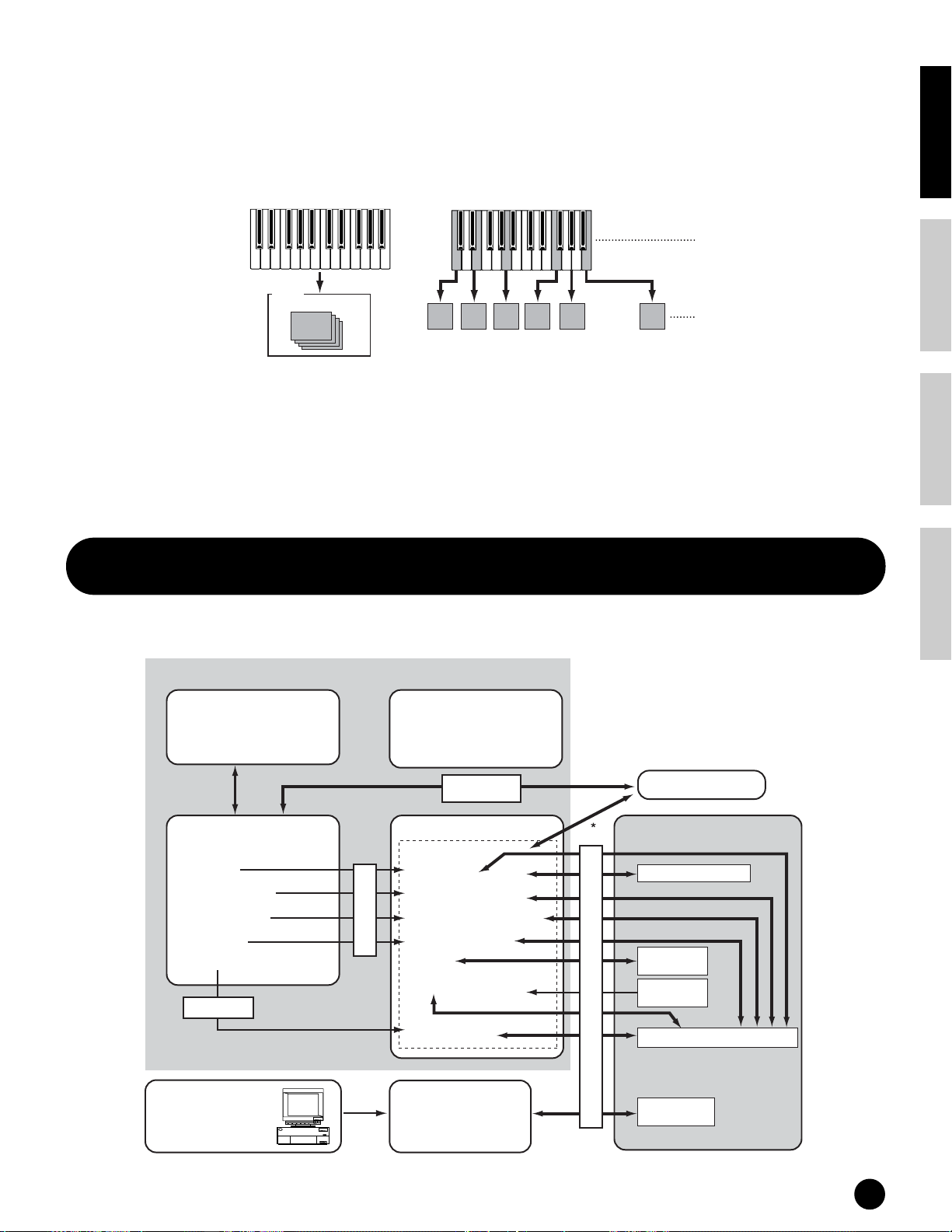
Normal Voices & Drum Voices
Internally, there are two Voice Types: Normal Voices and Drum Voices. Normal Voices are mainly pitched musical
instrument-type sounds that can be played over the range of the keyboard. Drum Voices are mainly percussion/drum
sounds that are assigned to individual notes on the keyboard. A collection of assigned percussion/drum wave or
Normal Voice is known as a Drum Kit.
Normal Voice Drum Voice
Voice
Element 1-4
Key 1 Key 2 Key 3 Key 4 Key 5 Key 76
GM Voices
GM is a worldwide standard for Voice organization and MIDI functions of synthesizers and tone generators. It was
designed primarily to ensure that any song data created with a specific GM device would sound virtually the same on
any other GM device — no matter the manufacturer or the model. The GM Voice bank on the S90 is designed to
appropriately play back GM song data. However, keep in mind that the sound may not be exactly the same as played
by the original tone generator.
Basics SectionQuick GuideReferenceAppendix
Internal Memory and File Management
In this section, how to store the various types of data and use the memory media for storing them.
This diagram details the relationship among the S90’s functions and the internal memory and memory card.
Recall Buffer
(DRAM)
* Voice/Performance only
Edit Buffer
(DRAM)
• Voice Edit
• Plug-in Voice Edit
• Performance Edit
• Master Edit
• Mixing Edit
Put (save)
S90 Internal Memory
Preset Data (ROM)
Flash ROM
• User Voice
(Normal 128, Drum 16)
• User Plug-in Voice
(64 Voices x 3 boards)
• User Performance (128)
Store
• User Master (128)
• Chain
• User Arpeggio (128)
• System setting
(Utility setting)
• Voice
• Plug-in Voice
• Preset Arpeggio
• Demo
MIDI bulk
User Memory
(Load only)
*
Bulk transmission cannot be used to
transfer the data of User Arpeggios
and part of the System settings.
External MIDI device
Memory Card
File extensions “.W4V”
File extensions
“.W4C”
File extensions
“.W2G”
Load / Save
File extensions “.W4A”
Computer
For editing Plug-in
Voices
Plug-in board
Personal System/V
PS/V
M
Personal System/V
IB
(DRAM)
• Plug-in All Bulk
File extensions
“.W2B”
Internal Memory and File Management
27
Page 28

Basics Section Quick Guide Reference Appendix
Internal Memory
● ROM and RAM
ROM (Read Only Memory) is memory designed specifically for reading out of data, and as such data cannot be
written to it. This is the location where preset data for the instrument is permanently stored.
On the other hand, RAM (Random Access Memory) allows both reading and writing of data. This is the location for
the edit buffer data.
● Flash ROM and DRAM
The data contained in Flash ROM can be read and written and maintained indefinitely, even if the power is off. This
is the location where the data created by editing is stored. On the other hand, data contained in DRAM is lost when
the power is turned off. Because of this, you should always store any data residing in DRAM to Flash ROM or a
memory card before turning off the power.
Never attempt to turn off the power while data is being written to Flash ROM (while an “Executing...” or “Please keep power on”
message is shown). Turning the power off in this state results in loss of all user data and may cause the system to freeze (due to
corruption of data in the Flash ROM).
Edit Buffer (DRAM) and Recall Buffer (DRAM)
● Edit Buffer and User Memory
The edit buffer is the memory location for edited data of these types: Voice, Performance and Master. Data edited in
this location will be stored to the User Memory.
If you select another Voice, Performance, Master, or Mixing setup, the entire contents of the edit buffer will be
rewritten with the newly selected Voice/Performance/Master/Mixing setup. Make sure to store any important data
before selecting another Voice, etc.
● Edit Buffer and Recall Buffer
If you’ve selected another Voice or Performance without storing the one you were editing, you can recall your
original edits, since the edit buffer’s contents are stored in backup memory. Keep in mind that the recall buffer is
available only in the Voice or Performance mode.
Memory Card
To properly protect and store your valuable User data, you should save it to Memory Card for indefinite safekeeping
(page 82).
There are two different ways to save data created on the S90 to memory card:
• By saving all data in the User memory as a single file (with the extension “.W4A”).
• By saving the files separately according to their specific functions (with the extensions corresponding
to each type).
28
Internal Memory and File Management
Page 29

Basic Operations
In this section, you’ll learn about the structure of the modes of the S90, its panel display indications and its
fundamental operations.
Modes
The S90 is organized into various modes, each covering a different set of operations and functions.
Basics SectionQuick GuideReferenceAppendix
Voice Mode
Voice Play Mode
Voice Edit Mode
Voice Job Mode
Voice Store Mode
Performance Mode
Performance Play Mode
Performance Edit Mode
Performance Job Mode
Performance Store Mode
Utility Mode
Edit Mode
VOICE
UTILITY
COMPARE
MODE
PERFORM
CARD
JOBEDIT
MASTER
SEQ PLAY
STORE
Master Mode
Master Play Mode
Master Edit Mode
Master Job Mode
Master Store Mode
Sequence Play Mode
Sequence Play Mixing Mode
Sequence Play Mixing
Edit Mode
Sequence Play Mixing
Job Mode
Card Mode
Store Mode
Job Mode
Mode Table
Mode (Status) Play
VOICE (LED lights) page 36 page 60 page 70 page 73 Play/Edit/Save the Voice
PERFORMANCE (LED lights) page 41 page 98 page 70 page 73 Play/Edit/Save the Performance
MASTER (LED lights) page 48 page 51 page 70 page 73
SEQ PLAY (LED lights) page 75
SEQ PLAY MIXING (Displayed)
UTILITY (LED lights)
CARD (LED lights)
EDIT (LED lights.
When comparing,
it flashes.)
page 79 page 70
JOB (Displayed) STORE (Displayed) Relevant function
Register/Recall the settings that are often
used in the Voice, Performance and
Sequence Play mode to User Master.
Make/Register Master Keyboard
function settings.
Song playback (from memory card)
Set the tone generation parameters of
each part in Sequence Play mode
(page 77).
page 72
Global settings for the entire system
(page 98)
Save/Load the S90 data (page 82)
n You need to select the Voice/Performance/Master before entering Edit mode. All parameters can be set and stored per Voice/
Performance/Master.
n Utility mode is a sub-mode of the Voice/Performance/Sequence Play mode. For example, if you press the [UTILITY] button while
in the Performance mode, you enter the Utility mode as a sub-mode of the Performance mode — allowing you to select and play
performances while in the Utility mode.
Parameters are divided into two basic groups: 1) functions that are related to each Voice, Performance etc., and 2)
functions that affect all Voices, Performances etc. The former are set in the Edit mode and latter in the Utility mode.
Utility mode settings can be saved to memory card along with the Voices and Performances.
Basic Operations
29
Page 30

Basics Section Quick Guide Reference Appendix
Selecting a Mode
Display Indications
There are separate Play modes for Performances/
Voices and Sequence Play mode. To enter each of these
modes, use the appropriate MODE button.
In the Sequence Play mode, there is a Mixing mode. To
enter the Mixing mode, press the [F6] button while
selecting the Sequence play mode.
To enter the Master mode, press the [MASTER]
button. Depending on the Master program, the
indicator of the VOICE/PERFORMANCE/SEQ PLAY
lights.
There are also separate Edit and Job modes for
Performances, Voices, Masters and Mixing setups. To
enter the Edit or Job mode, simply press the [EDIT] or
[JOB] button while in each respective mode.
Similarly, pressing the [STORE] button in the Voice,
Performance, Master mode takes you into the Store
mode where you can store Performances, Voices and
Masters.
In addition, the modes mentioned above, there is also a
Utility mode, which is for making global settings to the
instrument and the Card mode, which contains Card
related settings.
n Keep in mind that the particular displays and parameters
in the Utility mode differ depending on which main
mode was active before calling up the sub-mode.
n Note that the Mixing settings are memorized with the
“Put” function (not “Store”) (page 79).
To exit to another mode, press the respective button for
that mode or the [EXIT] button.
Here we explain how to read the display indications.
Voice Play Mode
1
2
3
6
Voice Play Mode (Quick Edit)
1
9
Voice Edit Mode
@
1
9
8
7
Performance Play Mode
1
2
3
6
7
4
5
243@
)
9)
2!43
)
45
)
9
Functions of the NUMBER [1] - [16] buttons
Use of these buttons differs depending on the on/off
status of the [TRACK SELECT] and [MUTE]
buttons.
Voice Play mode
Voice Edit mode
Performance
Play mode
Performance
Edit mode
Master Play
mode
Master Edit
mode
Sequence Play
mode
Mixing mode
30
Basic Operations
When [TRACK
SELECT] is on
Keyboard transmit
channel setting
Element selection (1 - 4) and Element
Mute setting (9 - 12)
Keyboard transmit
channel setting Per formance part
Performance part
selection (1 - 4)
Zone selection
(1 - 4)
Zone selection
(1 - 4)
Mixing part
selection
When [MUTE]
is on
—
Mute setting
(1 - 4)
—
Zone Mute setting
(1 - 4)
Mixing part Mute
setting
When both
[TRACK SELECT]
[MUTE] are off
Voice selection,
according to Groups
A - H
—
Performance or Voice
selection (if cursor is
located at Voice
name), according to
Groups A - H
Master selection,
according to Groups
A - H
—
—
Performance Play Mode (Quick Edit)
243@
1
99)
Performance Edit Mode
)
2!43@
1
9
8
7
)
)
9
Page 31

Master Play Mode
1
2
6
Indicates the mode
assigned to the
Master
Indicates the bank
number assigned to
the Master
5
Store Mode (Ex. Voice Store)
£
Basics SectionQuick GuideReferenceAppendix
Master Quick Edit Mode
42
Naming List
1
#
Master Edit Mode
1
!
42
1 Mode (PERF=PERFORMANCE)
2 Bank/Number
P1-P3 =PLG1-PLG3
3 Category (page 35)
4 Name (refer to the separate Data List)
5 Keyboard MIDI transmit channel (page 37)
Keyboard Octave setting set via the Octave parameter
Sequence Play Mode
^%&
1
(UTILITY [F1]→[SF1] Octave Ref. #17)
6 Functions assigned to the respective Control sliders
(3rd row). AS=ASSIGN (page 53)
7 Function (selected via [F1]-[F6]buttons)
$
¡
*(º ™
Sequence Play Mixing Mode
1
8 Sub-Function (selected via [SF1]-[SF5]buttons)
9 Parameter/function name (page 98)
) Settings
! Edit type
COMMON=Common Edit status
EL1-EL4=Element Edit status
KEY=Key Edit Status
9
PART01-PART16=Part Edit status
@
Edit indicator (Indicates the current Voice/
Performance has been modified but not yet stored; page
39. In the Compare condition,
Sequence Play Mixing Edit Mode
!
1
9)
shown; page 61.)
# Pop-up character list (page 35)
$ Chain Step number (page 75)
% Settings (Song file/Mix template)
the indicator
^ Tempo
& Song position
Job Mode (Ex. Voice Copy)
1
* Tempo button (page 76)
( Measure button (page 76)
º Folder setting button (page 75)
¡ Press the button to enter the Demo mode (page 19)
™ Press the button to enter the Mixing mode (page 77)
Source Voice Source Data Type
Destination Data Type
£ Destination for Store operation
is
Basic Operations
31
Page 32

Basics Section Quick Guide Reference Appendix
Selecting Functions
and Parameters
Using the Sub-Function
buttons [SF1] - [SF5]
Each mode described above contains various displays,
with various functions and parameters. To navigate
your way through these displays and select a desired
function, use the [F1] - [F6] buttons and the [SF1] [SF5] buttons.
When you select a mode, the available displays or
menus appear directly above the buttons at the bottom
of the display (as shown below).
Using the Function buttons
[F1] - [F6]
These functions can be selected via the
corresponding button ([F1] - [F6]).
SF1 SF2 SF3 SF4 SF5
F2F1 F3 F4 F5 F6
In this example, press the [F5]
button to go to the LFO display.
INFORMATION
These functions can be selected via the
corresponding button ([SF1]-[SF5]).
SF1 SF2 SF3 SF4 SF5
F2F1 F3 F4 F5 F6
In this example, press the [SF5]
button to go to the SCALE display.
INFORMATION
Depending on the currently selected mode, up to five
functions (sub-functions) are available and can be
called up with the [SF1] - [SF5] buttons. Keep in mind
that the available functions differ depending on the
selected mode. (Some displays may not have any subfunctions for these buttons.)
How to leave the
current display
For most operations (especially editing and Job- or
Store-related), pressing the [EXIT] button will let you
leave the current display and return you to the next
highest level or to the normal play mode display.
DEC/NO INC/YES
Depending on the currently selected mode, up to six
functions are available and can be called up with the
[F1] - [F6] buttons. Keep in mind that the available
functions differ depending on the selected mode.
n In some cases, the function buttons are used for special
operations, such as the ones in the Sequence Play
(CHAIN) display (page 76).
32
Basic Operations
EXIT ENTER
EXECUTE
[ENTER] button
Use this button to execute a Job or a Store operation.
Also use this button to actually enter a number when
selecting a Bank or Group for Voice or Performance. In
the File mode, use this button to go to the next lowest
level in the selected directory.
DEC/NO INC/YES
EXIT ENTER
EXECUTE
Page 33

Display-based Controls
Information Display
Data Entry
Changing (editing) values
Rotating the data dial to the right
(clockwise) increases the value, while
rotating it to the left (counterclockwise) decreases it.
DEC/NO INC/YES
EXIT ENTER
EXECUTE
Moving the cursor
Use these four cursor buttons to navigate the display, moving the cursor
around the various selectable items and parameters in the screen.
When selected, the relevant item is highlighted (the cursor appears as a
dark block with inverse characters).
When you exit from the Utility mode or Favorite
Category function, the parameter you changed in the
display is automatically stored. However, this edited data
is lost if you turn off the power without properly exiting
from the display.
For parameters with large value
ranges, you can increase the value by
10 by simultaneously holding down the
[INC/YES] button and pressing the
[DEC/NO] button. To decrease by 10,
do the opposite; simultaneously hold
down the [DEC/NO] button and press
the [INC/YES] button.
This convenient function lets you call up relevant
details about the selected mode — simply by pressing
the [INFORMATION] button. For example, when the
Voice mode is active, you can quickly check
information about which voice bank is selected, what
Play mode (poly or mono) is being used, which effects
are applied, and so on.
INFORMATION
In the Sequence Play mode, you can confirm the
selected (current) folder (directory).
Basics SectionQuick GuideReferenceAppendix
Never attempt to turn off the power while data is being
written to Flash ROM (while an “Executing...” or
“Please keep power on” message is shown). Turning the
power off in this state results in loss of all user data and
may cause the system to freeze (due to corruption of data
in the Flash ROM).
Confirmation Message
When you execute certain operations, such as those in
the Job, Store, and File modes, the S90 shows a
confirmation message. This lets you actually execute
the operation or cancel it if desired.
If a confirmation message (like the one illustrated above)
appears, press the [INC/YES] button to execute the
operation or press the [DEC/NO] button to cancel it.
INFORMATION
For details about Information Display, see page 114.
Basic Operations
33
Page 34

Basics Section Quick Guide Reference Appendix
Note (Key) settings
Several S90 parameters let you set a key range for a
function — for example, in setting up a keyboard split
— by specifying certain note values. You can use the
[INC/YES] and [DEC/NO] buttons or data dial to set
these parameters, or you can directly enter the values
from the keyboard by pressing the appropriate keys (as
shown below). In the example display here, Element 1
of a voice is being edited.
When Note Limit is selected, the [KBD] mark appears,
indicating that you can use the keyboard to set the value.
Simultaneously hold down the [INFORMATION] button and
press the appropriate key.
INFORMATION
1 Move the cursor to the first position of the name by
using the cursor buttons.
DEC/NO INC/YES
EXIT ENTER
EXECUTE
2 Select a character by using the [INC/YES] button,
[DEC/NO] button or the data dial.
Naming (Entering Characters)
The S90 allows you to create your own original data
such as voices, performances, masters. You can also
freely name the data as desired.
The following data types can be named.
• User voices page 66
• User performances page 43
• User masters pages 50, 52
• Mix templates page 79
• Files saved to memory card page 85
The example below applies when naming a User voice.
DEC/NO INC/YES
3 Move the cursor to the next position of the name by
using the cursor buttons.
DEC/NO INC/YES
EXIT ENTER
EXECUTE
34
Basic Operations
4 Enter the other characters as desired by repeating
steps 1 - 3 above.
Page 35
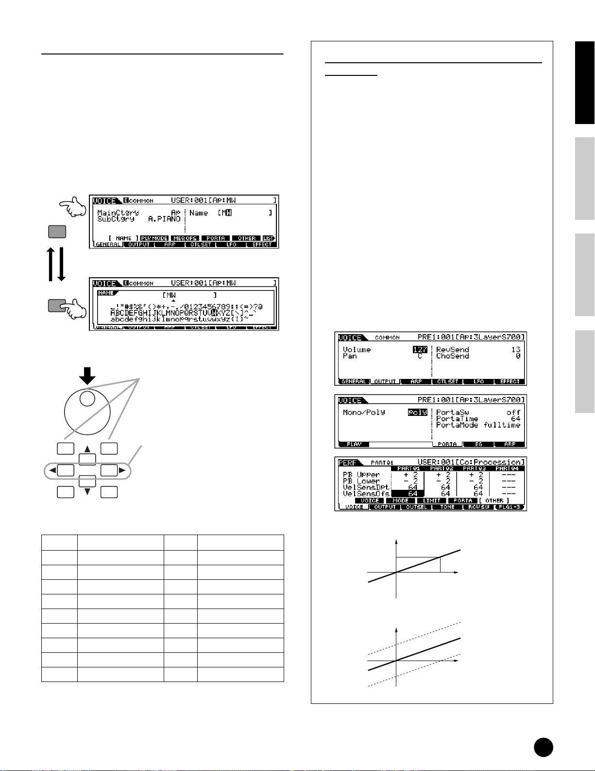
Using the Character List
In steps 2 and 3 above, you can use the special popup Character List, which shows you all the available
characters, making it exceptionally easy to enter names
and text. To call up the list, press and hold down the
[INFORMATION] button. To select a character, keep
holding down the [INFORMATION] button and use
the [INC/YES] and [DEC/NO] buttons or data dial.
When the cursor is located at the Name, this [LIST] icon appears and
you can call up the Character List display by holding the
[INFORMATION] button. Release the [INFORMATION] button to return
back to the original display.
INFORMATION
INFORMATION
Types of Parameters (Absolute and
Relative)
There are many ways to set parameters. Some
parameters require you to directly enter numerical
settings or alphabetic characters. With others, you
can choose from a number of available settings.
Furthermore, some types of parameters are
“absolute” whereas others are “relative.”
For example, the absolute parameter in the following
illustration can be set to either “mono” or “poly.”
For other absolute parameters such as Volume, the
setting can be any value between zero and 127. The
Volume setting has a linear, one-to-one relationship
with the actual volume, as shown in the graph on the
left. However, relative parameters do not follow the
same relationship. The graph on the bottom shows
the role of the Velocity Offset parameter. The value
you have set here, known as an “offset,” is added to,
or subtracted from, the actual value. With Velocity
Offset, the specified offset value is added to, or
subtracted from, the actual velocity of the notes you
play on the keyboard. Sometimes, these types of
relative parameters are set as a percentage.
Basics SectionQuick GuideReferenceAppendix
While holding the [INFORMATION] button....
Select a character by using the
[INC/YES] button, [DEC/NO]
button or the data dial.
DEC/NO INC/YES
EXIT ENTER
EXECUTE
LCD Category LCD Category
-- Unassigned Ld Synth Lead
Ap Acoustic Piano Pd Synth Pad
Kb Keyboard Sc Synth Comping
Or Organ Cp Chromatic Percussion
Gt Guitar Dr Drums
Ba Bass Se Sound Effects
St Strings/Orchestral Me Musical Effects
Br Brass Co Combination
Rp Reed/Pipe
Move the cursor to the desired position.
Use these two buttons to navigate the
display, moving the cursor around the
various selectable items and parameters in
the screen. When selected, the relevant
item is highlighted (the cursor appears as a
dark block with inverse characters).
1. Volume (absolute)
Volume
0
127
2. Velocity Sensitivity offset (relative)
Offset
+64
0
Offset added (+10)
Actual velocity
Offset subtracted (-10)
Volume
-64
Basic Operations
35
Page 36

Basics Section Quick Guide Reference Appendix
Quick Guide
Playing Voices
Here, you’ll learn how to select and play Voices (instrument sounds) from the PRESET1-3, GM, USER and PLG 1-3
memory groups (Banks).
n For details about voices, see pages 25, 26. For information on the Voice List, see the separate Data List.
n Up to 128 Normal Voices and 16 Drum Voices can be stored to User memory (pages 25, 27, 73). The Voice settings can be
changed in the Voice Edit mode (page 60).
Selecting a voice
14 234
3.3V
PITCH MODULATION
L
THRU
OUTINBREATH
ASSIGNABLESUSTAIN21A/D INPUTGAINRRL/MONOPHONESUSBCARD
MIDIFOOT SWITCHFOOT CONTROLLERASSIGNABLE OUTPUTOUTPUT
CONTROL
PAN
TEMPO
REVERB
CHORUS
FUNCTION
CUTOFF
RESONANCE
RELEASE
ATTACK
ASSIGN B
ASSIGN A
ASSIGN 2
ASSIGN 1
MEQ LOW
MEQ LOW MID
MEQ HI MID
MEQ HIGH
VOLUME 2
VOLUME 3
VOLUME 1
VOLUME 4
ZONE 2
ZONE 3
ZONE 1
ZONE 4
MASTER
CS 1
CS 4
CS 2
CS 3
VOLUME
SF1 SF2 SF3 SF4 SF5
F1 F2 F3 F4 F5 F6
INFORMATION
DEC/NO INC/YES
EXIT ENTER
MODE PROGRAM
VOICE
PERFORM
UTILITY
CARD
JOBEDIT
COMPARE
EFFECT
ARPEGGIO
BYPASS
EXECUTE
MASTER
DRUM KITS
PRE 1 PRE 2 PRE 3 GM USER PLG 1 PLG 2 PLG 3
A. PIANO
FAVORITES
COMMON
SEQ PLAY
A B C D E F G H
SYN LEAD SYN PAD/
STORE
1 2 3 4 5 6 7 8
ELEMENT / PERF.PART / ZONE
PLAY/
9 10 11 12 13 14 15 16
STOP
SLOT 1 SLOT 2 SLOT 3
CATEGORY
KEYBOARD
ORGAN BASS STRINGS BRASS REED/PIPEGUITAR/
SYN COMP
CHOIR
SEARCH
PLUCKED
REMOTE
CONTROL
CHROMATIC
DRUM/
SE
MUSICAL FX
COMBI
PERCUSSION
PERCUSSION
TRACK
SELECT
MUTE
SOLO
MUSIC SYNTHESIZER
Modular Synthesis Plug-in System
POWER
ON/ OFF
1 Enter the Voice Play mode.
MODE
VOICE
PERFORM
MASTER
When the Voice Play mode is active, the currently
selected voice is shown in huge letters — so you can
easily check which voice you’re about to play.
5
2 Select a Voice Bank.
● Normal Voice
PRE 1 PRE 2 PRE 3 GM USER
A. PIANO
KEYBOARD
ORGAN BASS STRINGS BRASS REED/PIPEGUITAR/
PLUCKED
Select a Normal Voice Bank. Select a Plug-in Voice Bank.
● Drum Voice
DRUM KITS
n When shipped from the factory, the S90 contains a full
set of specially programmed User voices in the User
bank. Naturally, you can edit these and overwrite them
if you want. You can also restore them to the original
factory set from the Utility Job (page 72). For details
about Voice Banks and Groups, see page 25.
PRE 1 PRE 2 PRE 3 GM USER
A. PIANO
KEYBOARD
PLG 1 PLG 2 PLG 3
ORGAN BASSGUITAR/
PLUCKED
Bank name
Bank name
36
Playing Voices
Page 37

3 Select a Voice Group.
Voices in each Bank are divided into Groups [A] - [H].
Select the desired Group, and all the Voices of that
Group are shown in the display.
Group
A B C D E F G H
SYN LEAD SYN PAD/
CHOIR
SYN COMP
CHROMATIC
PERCUSSION
DRUM/
PERCUSSION
SE
MUSICAL FX
COMBI
4 Select a Voice number.
Decreases
number
Decreases
DEC/NO INC/YES
number
1 2 3 4 5 6 7 8
ELEMENT / PERF.PART / ZONE
9 10 11 12 13 14 15 16
Increases
number
Increases
number
● Program numbers and the corresponding
Group/Numbers
Program
Number
001 A 1 065 E 1
002 A 2 066 E 2
003 A 3 067 E 3
004 A 4 068 E 4
005 A 5 069 E 5
006 A 6 070 E 6
007 A 7 071 E 7
008 A 8 072 E 8
009 A 9 073 E 9
010 A 10 074 E 10
011 A 11 075 E 11
012 A 12 076 E 12
013 A 13 077 E 13
014 A 14 078 E 14
015 A 15 079 E 15
016 A 16 080 E 16
017 B 1 081 F 1
018 B 2 082 F 2
019 B 3 083 F 3
020 B 4 084 F 4
021 B 5 085 F 5
022 B 6 086 F 6
023 B 7 087 F 7
024 B 8 088 F 8
025 B 9 089 F 9
026 B 10 090 F 10
027 B 11 091 F 11
028 B 12 092 F 12
029 B 13 093 F 13
030 B 14 094 F 14
031 B 15 095 F 15
032 B 16 096 F 16
033 C 1 097 G 1
034 C 2 098 G 2
035 C 3 099 G 3
036 C 4 100 G 4
037 C 5 101 G 5
038 C 6 102 G 6
039 C 7 103 G 7
040 C 8 104 G 8
041 C 9 105 G 9
042 C 10 106 G 10
043 C 11 107 G 11
044 C 12 108 G 12
045 C 13 109 G 13
046 C 14 110 G 14
047 C 15 111 G 15
048 C 16 112 G 16
049 D 1 113 H 1
050 D 2 114 H 2
051 D 3 115 H 3
052 D 4 116 H 4
053 D 5 117 H 5
054 D 6 118 H 6
055 D 7 119 H 7
056 D 8 120 H 8
057 D 9 121 H 9
058 D 10 122 H 10
059 D 11 123 H 11
060 D 12 124 H 12
061 D 13 125 H 13
062 D 14 126 H 14
063 D 15 127 H 15
064 D 16 128 H 16
Group Number Program
Number
Group Number
Basics SectionQuick GuideReferenceAppendix
5 Play the keyboard.
Keyboard MIDI transmit channel setting
Press the [TRACK SELECT] button so that its
indicator lights, and press any of the NUMBER [1] [16] buttons to change the Keyboard MIDI transmit
channel.
1 2 3 4 5 6 7 8
ELEMENT / PERF.PART / ZONE
9 10 11 12 13 14 15 16
n You can set this parameter also in the Utility mode
([F5]→
[SF1] KBDTransCh Ref. #177). This
parameter cannot be stored in the Store mode.
Playing Voices
TRACK
SELECT
MUTE
SOLO
37
Page 38

Basics Section Quick Guide Reference Appendix
Using the Category Search function
The S90 features a powerful Category Search function that gives you quick access to the sounds you want,
irrespective of their bank locations. Simply select a voice category, such as A. PIANO or SYN LEAD, and you can
browse through all related voices one by one — and audition each of them, too. Plus, you can use the special
Favorites category to store the voices you use most.
132
3.3V
PITCH MODULATION
L
THRU
OUTINBREATH
ASSIGNABLESUSTAIN21A/D INPUTGAINRRL/MONOPHONESUSBCARD
MIDIFOOT SWITCHFOOT CONTROLLERASSIGNABLE OUTPUTOUTPUT
CONTROL
PAN
TEMPO
REVERB
CHORUS
FUNCTION
CUTOFF
RESONANCE
RELEASE
ATTACK
ASSIGN A
ASSIGN B
ASSIGN 2
ASSIGN 1
MEQ LOW
MEQ HIGH
MEQ LOW MID
MEQ HI MID
VOLUME 1
VOLUME 4
VOLUME 2
VOLUME 3
ZONE 1
ZONE 4
ZONE 2
ZONE 3
MASTER
CS 1
CS 4
CS 2
CS 3
VOLUME
SF1 SF2 SF3 SF4 SF5
F1 F2 F3 F4 F5 F6
INFORMATION
DEC/NO INC/YES
EXIT ENTER
MODE PROGRAM
VOICE
PERFORM
UTILITY
CARD
JOBEDIT
COMPARE
EFFECT
ARPEGGIO
BYPASS
EXECUTE
MASTER
DRUM KITS
PRE 1 PRE 2 PRE 3 GM USER PLG 1 PLG 2 PLG 3
A. PIANO
FAVORITES
COMMON
SEQ PLAY
A B C D E F G H
SYN LEAD SYN PAD/
STORE
1 2 3 4 5 6 7 8
ELEMENT / PERF.PART / ZONE
PLAY/
9 10 11 12 13 14 15 16
STOP
SLOT 1 SLOT 2 SLOT 3
CATEGORY
KEYBOARD
ORGAN BASS STRINGS BRASS REED/PIPEGUITAR/
SYN COMP
CHOIR
SEARCH
PLUCKED
REMOTE
CONTROL
CHROMATIC
DRUM/
SE
MUSICAL FX
COMBI
PERCUSSION
PERCUSSION
TRACK
SELECT
MUTE
SOLO
MUSIC SYNTHESIZER
Modular Synthesis Plug-in System
POWER
ON/ OFF
1 Turn the Category Search
function on by pressing the
[CATEGORY SEARCH] button.
PRE 1 PRE 2 PRE 3 GM USER PLG 1 PLG 2 PLG 3
A. PIANO
KEYBOARD
ORGAN BASS STRINGS BRASS REED/PIPEGUITAR/
PLUCKED
n To turn the function off, press [CATEGORY SEARCH]
button again.
CATEGORY
SEARCH
2 Select a Category.
■ Select a Category
Press the Category buttons to display the Category name and
the voice list. The first voice in this Category is selected.
PRE 1 PRE 2 PRE 3 GM USER PLG 1 PLG 2 PLG 3
■ Select a Sub Category
All Categories are divided into two or three Sub
Categories for further ease in selection. The Sub
Category names are displayed at the bottom of the
Category Search display. Press the [F1] - [F3] buttons to
select the first voice in the corresponding Sub Category.
SF1 SF2 SF3
F2F1 F3
3 Select a voice and play it.
Step through the available voices by using the data dial.
You can also use the [INC/YES] and [DEC/NO] buttons,
or use the cursor [▲]/[▼] buttons.
play and audition each Voice as you select it — without
having to leave the Category Search function.
Remember, you can
Category
names
38
Playing Voices
A. PIANO
KEYBOARD
ORGAN BASS STRINGS BRASS REED/PIPEGUITAR/
SYN COMP
PLUCKED
CHROMATIC
PERCUSSION
DRUM/
PERCUSSION
SE
MUSICAL FX
A B C D E F G H
SYN LEAD SYN PAD/
CHOIR
Category name Voice list
DEC/NO INC/YES
COMBI
EXIT ENTER
EXECUTE
Page 39

To actually call up the Voice and return to the Play
mode, press the [ENTER] button.
Voice editing in the
Voice Play mode
Favorite Category
Use this convenient function to store all your favorite,
often-used voices in a single, easy-to-access location —
and call them up by pressing the [FAVORITES] button.
Select any voice you want, from any desired category,
and enter each to the Favorites Category. In this way,
you can go directly to all the voices you use the most,
without having to hop around other Categories — a
great aid when playing live.
Select the desired Category, then move the cursor to
your favorite voice in the Category list, and press the
[F5] button to checkmark the box next to the voice
name. (You can un-checkmark it by pressing the [F5]
button again.) Go on to other Categories and continue
registering your favorites. After you’ve checkmarked
all the voices you want, press the [FAVORITES] button
to store them to the Favorites Category. All the voices
you’ve checkmarked — and only those voices — will be
shown in the list. To exit from the Favorites Category,
simply press the [FAVORITES] button again.
When you exit from the Favorite Category
function, the parameter you changed in the display
is automatically stored. However, this edited data
is lost if you turn off the power without properly
exiting from the display.
Never attempt to turn off the power while data is
being written to Flash ROM (while an
“Executing...” or “Please keep power on” message
is shown). Turning the power off in this state
results in loss of all user data and may cause the
system to freeze (due to corruption of data in the
Flash ROM).
(Quick Edit)
The Voice Play mode lets you perform a variety of
general editing operations on the selected voice. For
more detailed and comprehensive editing operations,
use the Voice Edit mode.
1 Select the desired Voice (page 36).
2 Select the menu you wish to edit by pressing the
[F4] - [F6] buttons and edit the parameters in each
display.
n When the Plug-in voice is selected (when the Single
part Plug-in board is installed), you can press the [F2]
button to call up the BANK display.
3 Store the settings edited in step 2 to the User
Memory as required (page 73).
4 Press the [F1] button to return to the original
display.
n Depending on the particular Plug-in Voice, certain
parameters may not be available for editing.
n Parameters in the Voice Play mode and Voice Edit mode
having the same name also have the same functions and
settings.
The [ ] Indicator
If you alter any parameters, the [ ] indicator will
appear in the top left of the display. This indicates
that the current settings have been modified but not
yet stored.
Basics SectionQuick GuideReferenceAppendix
SF1 SF2 SF3 SF4 SF5
F2F1 F3 F4 F5 F6
DRUM KITS
FAVORITES
Pressing this toggles
between the two settings:
Checkmark on
Checkmark off
Edit indicator
If you select another program or mode during
editing, the [ ] indicator will disappear and all
your edits will be lost. It is a good idea to store the
edited data from the Store mode (page 73). Even if
you lose the edited data, you can restore it by using
the Edit Recall function (page 71).
Playing Voices
39
Page 40
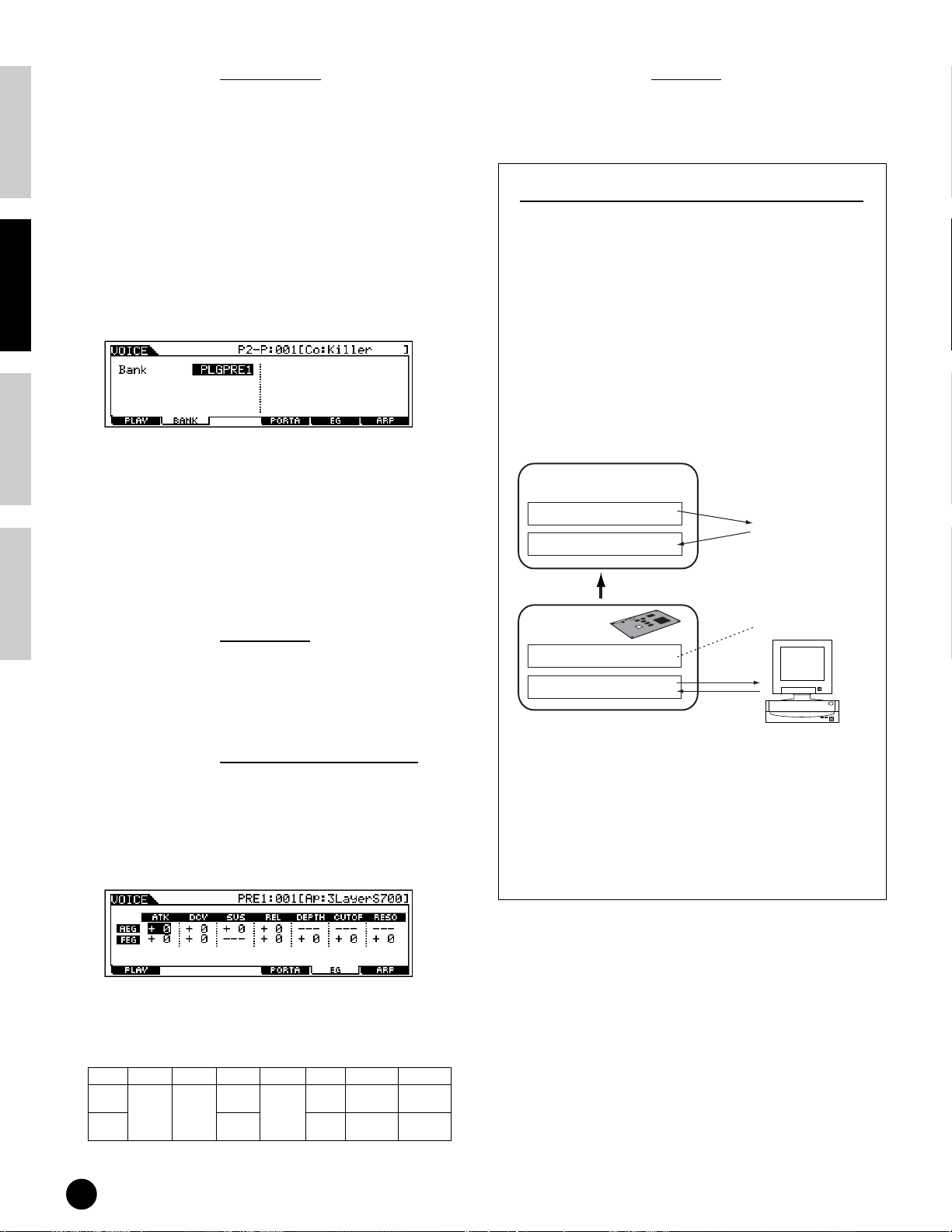
Basics Section Quick Guide Reference Appendix
● [F2] Voice Play Plug-in Bank
From this display you can select the particular bank
on the Plug-in board, and determine whether you
will be using a Plug-in voice or a “Board” voice.
Simply put, the difference between the two types of
voices is this:
• Board voices are unprocessed, unaltered voices of
the Plug-in board — the “raw material” for Plugin voices.
• Plug-in voices are edited Board voices — voices
that have been specially programmed and
processed for optimum use with the S90.
❏
Settings (with Plug-in Board installed to Slot 1)
PLG1USR (User Plug-in voice), PLGPRE1
(Preset Plug-in voice), 032/000... (Indicates
the Bank Select MSB/LSB of the Board voice.
These values differ depending on the installed
Plug-in board)
n This display is available only when the Plug-in board
is installed to the S90 and the Plug-in voice is
selected.
● [F4] Voice Play Portamento
From this display you can select monophonic or
polyphonic playback and set the Portamento
parameters (Voice Edit Common [F1]→ [SF4] Ref.
#7, 8, 10, 11).
● [F5] Voice Play EG (
Envelope Generator)
● [F6] Voice Play Arpeggio
This display contains the basic settings for Arpeggio
playback, including Type and Tempo (page 45).
About Plug-in voices and Board voices
The voices of a Plug-in Board installed to the S90
can be divided into two types: Board voices and
Plug-in voices. Board voices are unprocessed,
unaltered voices of the Plug-in board — the “raw
material” used for the Plug-in voices. Plug-in voices,
on the other hand, are edited Board voices — voices
that have been specially programmed and processed
for optimum use with the S90.
Included among the Board voices is a special set of
voices — called Board Custom voices — which can
be edited by a computer connected to the S90, using
special editing software included with the Plug-in
board. (See page 73.)
Plug-in voice
Plug-in preset voice
Plug-in user voice
S90 voice parameter
Board voice
Board preset voice
Board custom voice
Copy
Plug-in
Voice Edit
Store
Cannot be edited
Save
Bulk send/
edit
Computer
(Voice Editor in CD-ROM
supplied with the Plug-in board)
This display contains the basic EG settings, both
volume and filter, for the voice, as well as the filter’s
cutoff frequency and resonance settings. The
settings made here are applied as offsets to the AEG
and FEG settings in the Edit mode (pages 65, 66).
The full names of the available parameters are
shown in the chart below, as they appear in the
display.
ATK DCY SUS REL DEPTH CUTOFF RESO
AEG
Attack
time
FEG --- Depth
40
Playing Voices
Decay
time
Sustain
level
Release
Time
--- --- --Cutoff
frequency
Resonance
n Depending on the particular Plug-in board you are
using, some of the parameters may not be available.
For details, refer to the relevant owner’s manual of
the Plug-in board.
n For details on the current lineup of available Plug-
in boards, see page 21.
Page 41
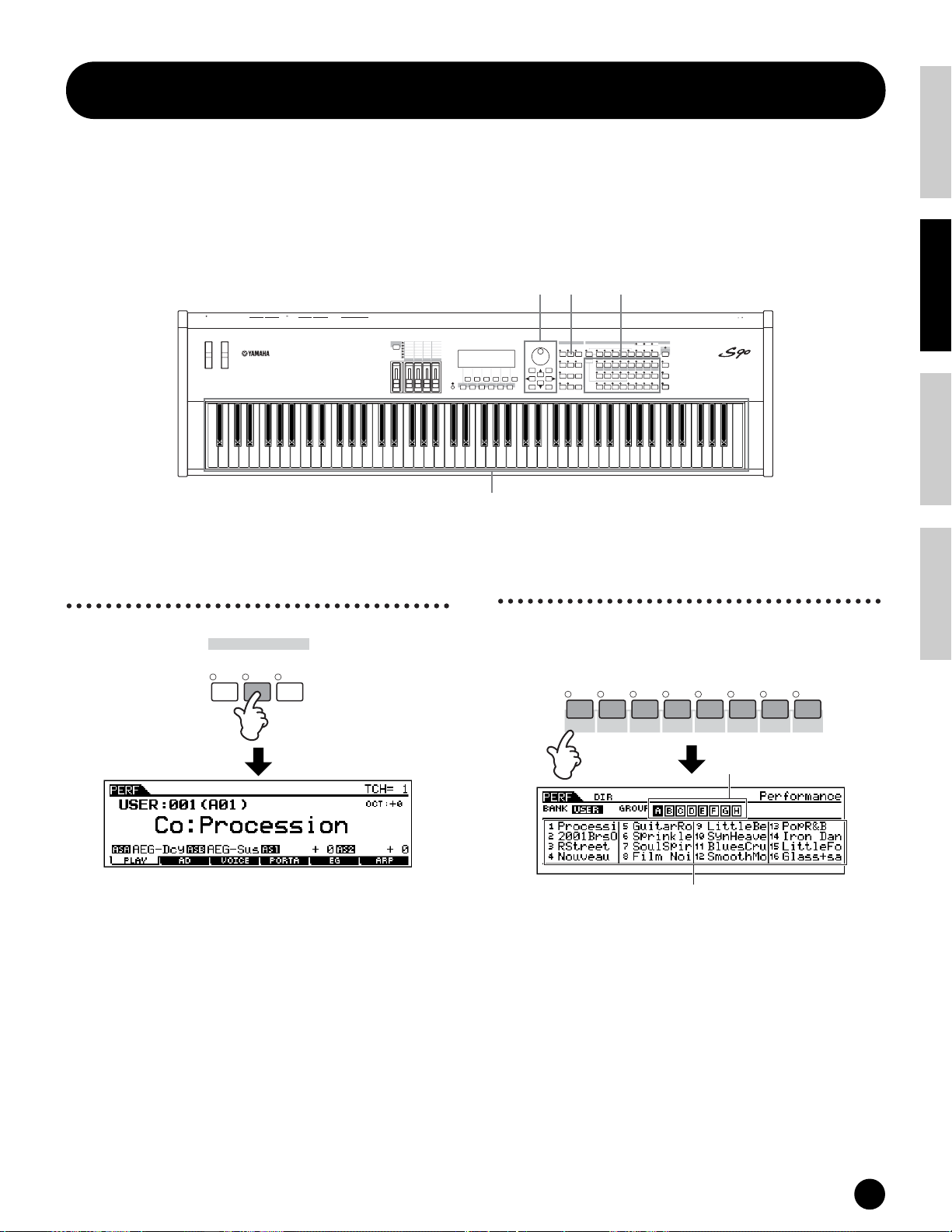
Playing Performances
In the Performance mode, you can select and play individual User performances.
n For details about the performances and their memory (bank) structure, see page 26.
Selecting a Performance
1323
3.3V
PITCH MODULATION
L
THRU
OUTINBREATH
ASSIGNABLESUSTAIN21A/D INPUTGAINRRL/MONOPHONESUSBCARD
MIDIFOOT SWITCHFOOT CONTROLLERASSIGNABLE OUTPUTOUTPUT
CONTROL
PAN
TEMPO
REVERB
CHORUS
FUNCTION
CUTOFF
RESONANCE
RELEASE
ATTACK
ASSIGN A
ASSIGN B
ASSIGN 2
ASSIGN 1
MEQ LOW
MEQ LOW MID
MEQ HI MID
MEQ HIGH
VOLUME 2
VOLUME 3
VOLUME 1
VOLUME 4
ZONE 2
ZONE 3
ZONE 1
ZONE 4
MASTER
CS 1
CS 4
CS 2
CS 3
VOLUME
SF1 SF2 SF3 SF4 SF5
F1 F2 F3 F4 F5 F6
INFORMATION
DEC/NO INC/YES
EXIT ENTER
MODE PROGRAM
VOICE
PERFORM
UTILITY
CARD
JOBEDIT
COMPARE
EFFECT
ARPEGGIO
BYPASS
EXECUTE
MASTER
DRUM KITS
PRE 1 PRE 2 PRE 3 GM USER PLG 1 PLG 2 PLG 3
A. PIANO
FAVORITES
COMMON
SEQ PLAY
A B C D E F G H
SYN LEAD SYN PAD/
STORE
1 2 3 4 5 6 7 8
ELEMENT / PERF.PART / ZONE
PLAY/
9 10 11 12 13 14 15 16
STOP
KEYBOARD
ORGAN BASS STRINGS BRASS REED/PIPEGUITAR/
PLUCKED
SYN COMP
CHROMATIC
CHOIR
PERCUSSION
4
Basics SectionQuick GuideReferenceAppendix
POWER
ON/ OFF
SLOT 1 SLOT 2 SLOT 3
CATEGORY
SEARCH
MUSIC SYNTHESIZER
Modular Synthesis Plug-in System
REMOTE
CONTROL
DRUM/
SE
MUSICAL FX
COMBI
PERCUSSION
TRACK
SELECT
MUTE
SOLO
1 Enter the Performance
Play mode.
MODE
VOICE
PERFORM
MASTER
When the Performance Play mode is active, the
currently selected performance is shown in huge letters
— so you can easily check which performance you’re
about to play.
2 Select a Performance
Group.
Performances in each Bank are divided into Groups
A~H. Select the desired Group, and all the
Performances of that Group are shown in the display.
A B C D E F G H
SYN LEAD SYN PAD/
n All performances are stored to a single bank, so you need
not select a bank here.
CHOIR
SYN COMP
CHROMATIC
DRUM/
PERCUSSION
PERCUSSION
Performance
Group
SE
MUSICAL FX
COMBI
Playing Performances
41
Page 42

Basics Section Quick Guide Reference Appendix
3 Select a Performance
number.
To solo part
1 2 3 4 5 6 7 8
TRACK
SELECT
1 2 3 4 5 6 7 8
ELEMENT / PERF.PART / ZONE
9 10 11 12 13 14 15 16
Decreases
number
Decreases
number
DEC/NO INC/YES
Increases
number
Increases
number
4 Play the keyboard.
ELEMENT / PERF.PART / ZONE
9 10 11 12 13 14 15 16
MUTE
SOLO
NUMBER
Simultaneously hold down the [MUTE] button and
press one of the NUMBER buttons [1] to [4] to solo
the corresponding part.
Once you’ve selected a part for soloing, the [MUTE]
button’s lamp flashes, indicating the Solo function is
active. While Solo is active, you can change the
soloed track simply by pressing the corresponding
NUMBER button [1] to [4].
To exit from the Solo function, press the [MUTE]
button again.
Layering Voices (Parts)
Together (Layer)
Splitting the Keyboard
n The Category Search function (page 38) can be used also
in the Performance Play mode in the same way as in the
Voice Play mode.
n The MIDI transmit channel can be set in the same way
as in the Voice mode.
Performance Part on/off
Each performance can contain a maximum of four
parts, selected from a total of seven — internal Parts
1 - 4 and Plug-in Parts 1 - 3.
n This operation is available also in the Edit mode.
1 Press the [MUTE] button so that its indicator
lights.
1 2 3 4 5 6 7 8
ELEMENT / PERF.PART / ZONE
9 10 11 12 13 14 15 16
2 Press any of the [1] - [4] buttons you wish to
mute. The part corresponding to the unlit
indicator is muted.
TRACK
SELECT
MUTE
SOLO
(Split)
Performances can be made up of a maximum of four
parts (voices), selected from the internal tone
generator Parts 1 - 4 and Plug-in board Parts 1 - 3.
You can create a performance by layering several voices
together, and/or by assigning different voices to
separate ranges of the keyboard. You can then store up
to 128 of your original, edited performances (page 73)
to internal User memory (page 28).
Layer
Built-in tone generator parts Plug-in parts
PRE1 PRE2 PRE3 USER PL1 PL2 PL3
Split
Built-in tone generator parts Plug-in parts
PRE1 PRE2 PRE3 USER PL1 PL2 PL3
3 Press the [MUTE] button again so that its
indicator goes out.
42
Playing Performances
Page 43
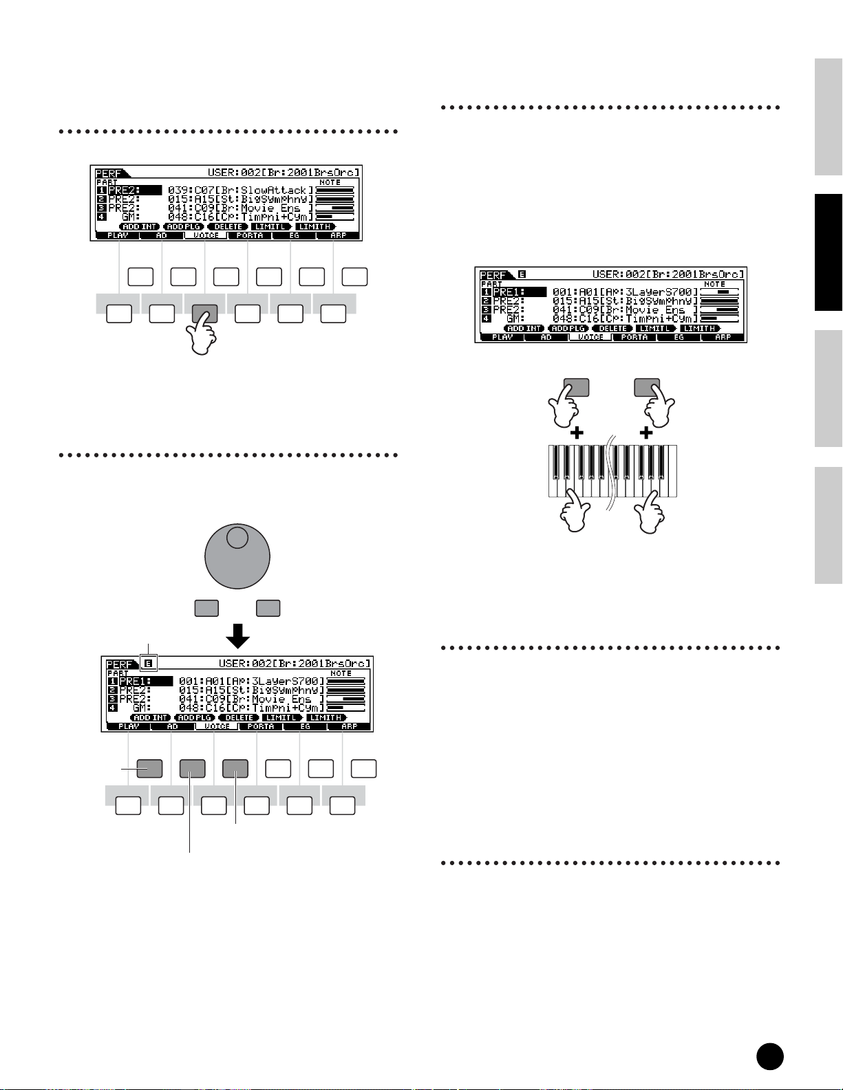
1 Call up the VOICE display
3 Specify the note range of
by pressing the [F3] button in
the Performance Play mode.
SF1 SF2 SF3 SF4 SF5
F2F1 F3 F4 F5 F6
INFORMATION
2 Assign the desired voice to
each part.
Move the cursor to the desired part and select a voice
by pressing the [F1] or [F2] button.
each part, as required.
You can set the lowest note of the range over which the
voice of the selected part sounds by pressing the
desired key while holding the [SF4] button. To set the
highest note of the range, press the desired key while
holding the [SF5] button.
This lets you create a split keyboard, with up to four
different parts (voices) sounding in four different
ranges. You can also overlap parts to create layers.
Note Limit Low
SF4 SF5
Note Limit High
Basics SectionQuick GuideReferenceAppendix
Edit indicator (page 39)
Assign the
built-in voice
to the
selected part.
DEC/NO INC/YES
SF1 SF2 SF3 SF4 SF5
F2F1 F3 F4 F5 F6
Delete the voice assignment
of the selected part.
Assign the Plug-in voice
to the selected part.
INFORMATION
4 Change the volume of each
part and adjust the relative
balance among the four parts
When the CONTROL FUNCTION is set to VOLUME,
you can adjust the volume of each part by using the
Control sliders.
n The Portamento, EG (Envelope Generator), and
Arpeggio parameters can be edited by calling up the
corresponding display via the [F4] - [F6] buttons in the
same way as in the Voice mode.
A wider variety of detailed editing controls is also
available in the Performance Edit mode. See page 98.
5 Store the settings.
Before exiting from the Performance Edit mode, make
sure to store the settings you made to the Performance
(page 73).
Playing Performances
43
Page 44

Basics Section Quick Guide Reference Appendix
Editing
Performances in the
Performance Play
mode (Quick Edit)
The Performance Play mode lets you perform a variety
of general editing operations on the selected
performance. For more detailed and comprehensive
editing operations, use the Performance Edit mode.
n Parameters in the Performance Play mode and
Performance Edit mode having the same name also have
the same functions and settings.
● [F2] Performance Play A/D
From this display you can make settings for the A/D
input parts. The A/D input feature lets you input
external audio (such as from a microphone or
guitar), then process and mix it with the other
sounds of the S90. The audio signal can be input via
the A/D INPUT jack or the mLAN terminal (if an
optional mLAN8E has been installed).
n For details about effect connection, see page 67.
In the Utility mode, you can set whether you use the A/
n
D INPUT jack or the mLAN8E terminal as an input jack
for the A/D part ([F2]
• Volume
Determines the output level of the A/D part.
• Pan
Determines the stereo pan position of the A/D part.
• RevSend
Determines the Send level of the A/D part signal
sent to the Reverb effect.
• ChoSend
Determines the Send level of the A/D part signal
sent to the Chorus effect.
→
[SF1] A/DSource Ref. #53).
• Mono/Stereo (mLAN Input)
Determines the signal configuration for the mLAN
audio (input), or how the signal or signals are routed
(stereo or mono). This parameter can be set only
when the mLAN terminal (with the optional
mLAN8E installed) is set as the input source for the
A/D part.
❏Settings
eo
ster
Audio received via mLAN terminal is processed in stereo.
L (left) mono
Audio received the L (left) channel via mLAN terminal is
processed in mono.
R (left) mono
Audio received the R (right) channel via mLAN terminal
is processed in mono.
L+R mono
Audio received via mLAN terminal is mixed and
processed in mono.
• OutputSel (Output Select)
Determines the output jack assignment for the A/D
part.
❏ Settings (below)
LCD Output Jack
L&R OUTPUT L&R Stereo
as L&R ASSIGNABLE OUTPUT L&R Stereo
as1&2 mLAN8E ASSIGNABLE OUTPUT 3&4
as3&4 mLAN8E ASSIGNABLE OUTPUT 3&4
asL ASSIGNABLE OUTPUT L Mono
asR ASSIGNABLE OUTPUT R Mono
as1 mLAN8E ASSIGNABLE OUTPUT1 Mono *
as2 mLAN8E ASSIGNABLE OUTPUT2 Mono *
as3 mLAN8E ASSIGNABLE OUTPUT3 Mono *
as4 mLAN8E ASSIGNABLE OUTPUT4 Mono *
* Available only when the optional mLAN8E board has been installed.
Stereo/
Mono
Stereo
1 : L
2 : R
Stereo
3 : L
4 : R
● [F3] Performance Play Voices
From this display you can select a voice for each
part and determine the note range it can be played
from (page 43).
*
*
• VarSend(Variation Send)
Determines the Send level of the A/D part signal
sent to the Variation effect.
• DryLevel
Determines the level of the unprocessed A/D part
— in other words, the signal not affected by the
System Effects (Reverb, Chorus, Variation; Utility
[F1]→[SF3] Ref. #21).
44
Playing Performances
● [F4] Performance Play P
ortamento
From this display you can set the Portamento
parameters for each part (Performance Edit
[F1]→[SF4] Ref. #7-10).
[F5] Performance Play EG (Envelope Generator)
●
Same as in Voice Play mode. See page 40.
● [F6] Performance Play Arpeggio
This display contains the basic settings for Arpeggio
playback, including Type and Tempo (page 45).
Page 45

Using the Arpeggio function
What is the Arpeggio
function?
This function automatically triggers preset arpeggio
phrases, according to the keys you play.
It is particularly suited to dance/techno music genres.
You can assign the desired Arpeggio Types to each
Voice/Performance, and adjust the tempo. You can also
set the Arpeggio playback method, Velocity range and
Play Effects to create your own original grooves.
What’s more, Arpeggio playback can be transmitted
through the MIDI Out (Ref. #86), letting you record
the Arpeggio data to a sequencer or play it back from
another tone generator.
Arpeggio structure
The following illustration shows the Arpeggio structure.
In the Voice
mode
Voice
Arpeggio data
Preset 1
(128)
Arpeggio
In the Performance
mode
Performance
Arpeggio on/off during Song playback
Basics SectionQuick GuideReferenceAppendix
Arpeggio On/Off can be set individually for each
part of a Song (Mixing mode). Just like playing
Arpeggios manually from the keyboard, this inserts
Arpeggios in the playback of Song sequence data
(page 79).
Four playback categories
of Arpeggio
Arpeggio types are divided into the four following
categories.
Sq: Sequence
Creates a general arpeggio phrase. Mainly octave up/
down phrases.
Ph: Phrase
Creates phrases that are more musical and
rhythmically varied than Sequence. Starting with
“Techno,” there are phrases for a wide variety of
musical genres, and for creating backing tracks for
guitar, piano and other instruments.
Voice
Preset 2
Voice
Voice
Voice
Voice Performance
Different Arpeggio types can assigned
to each Voice/Performance.
* User Arpeggio data of the MOTIF can be loaded.
(128)
Arpeggio
User *
(128)
Arpeggio
Performance
Performance
Performance
Performance
Dr: Drum Pattern
Creates drum pattern-type phrases. Any note produces
the same drum pattern.
This type is ideal for use with drum and percussion
sounds.
Ct: Control
Creates dynamic tonal and volume changes by using
control change data. No note data is created — the
tonal variations affect the played notes.
Using the Arpeggio function
45
Page 46

Basics Section Quick Guide Reference Appendix
Arpeggio playback
1 Select a Voice/
Performance (pages 36, 41).
2 Turn the Arpeggio on by
Arpeggio Type,
Tempo, and Limit
A variety of Arpeggio types are provided with the S90.
You can change the tempo of Arpeggio as desired.
The Arpeggio function is available in all modes.
The explanation below applies to the Performance Play
mode.
pressing the [ARPEGGIO]
button.
EFFECT
BYPASS
PLAY/
STOP
ARPEGGIO
n When you select a voice or performance for which the
Arpeggio Switch is set to on, the [ARPEGGIO] button is
automatically turned on.
n The on/off status of the [ARPEGGIO] button can be
stored to each voice or performance setup
(page 73).
3 Play the keyboard.
While holding the key(s), the Arpeggio is played back
according to the played note, Arpeggio type, tempo,
note limit settings, and so on.
n In the Voice Play mode, the Arpeggio is played back via
the selected voice.
n In the Performance/Mixing mode, the Arpeggio is played
back via the voice assigned to the selected part when the
Arpeggio Switch (Part Edit [F1]→[SF2] Ref. #77) of the
selected part is set to on (page 47).
1 Call up the ARP (Arpeggio)
display by pressing the [F6]
button in the Performance
Play mode.
SF1 SF2 SF3 SF4 SF5
F2F1 F3 F4 F5 F6
INFORMATION
2 Select an Arpeggio Bank.
Move the cursor to the Bank parameter and select.
46
Using the Arpeggio function
3 Select an Arpeggio Type.
Move the cursor to the Type parameter and select.
Page 47
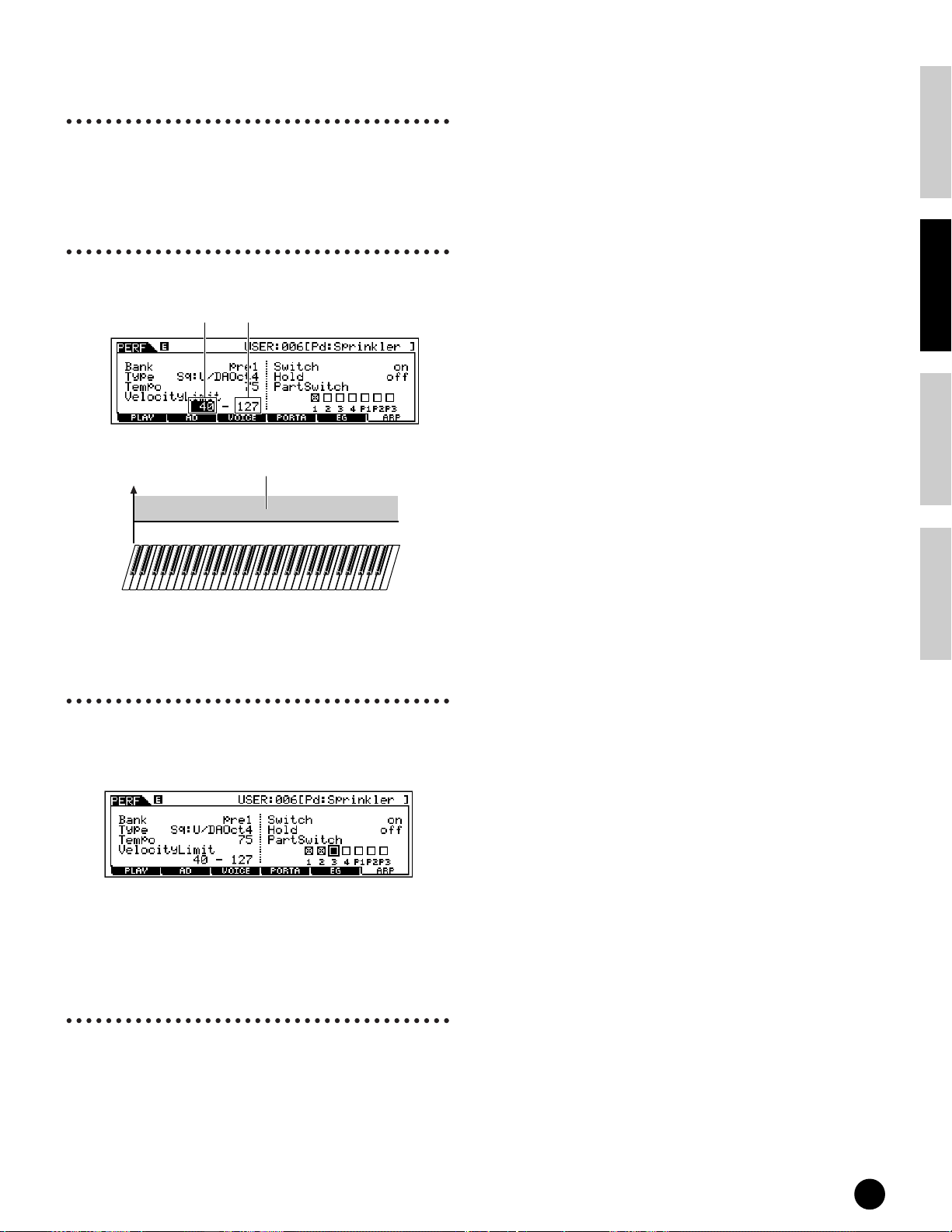
4 Set the Tempo for Arpeggio
playback.
Move the cursor to the Tempo parameter and set it.
5 Set the Velocity Limit for
Arpeggio playback.
Move the cursor to the Velocity Limit parameter and set it.
Low Limit High Limit
The Arpeggio is played back only when the
key is played at a velocity within this range
127
High Limit
Low Limit
0
(stronger than normal).
Basics SectionQuick GuideReferenceAppendix
6 Set the Arpeggio part
switch. (Performance only)
You can set the Arpeggio playback on or off for each
part. Move the cursor to the box of the desired part
and checkmark the box to turn the part on.
7 Store the Arpeggio settings
to the desired User
Performance (page 73).
Using the Arpeggio function
47
Page 48

Basics Section Quick Guide Reference Appendix
Using as a Master Keyboard
What is the Master
Mode?
The S90 is loaded with such a wealth of different
features, functions and operations, you may find it
difficult to locate and call up the particular feature you
need. This is where the Master mode comes in handy.
You can use it to memorize the operations you use
most often in each mode, and call them up instantly
anytime you need them with a single button press.
The S90 has space for a total of 128 of your own User
Master settings.
Master number Setting examples
Master 001 Voice mode Voice number 102
Master 002 Voice mode Voice number 88
Master 003 Performance mode Performance number 043 *Zone Switch Off
Master 004 Performance mode Performance number 059 *Zone Switch Off
Performance mode Performance number 077 *Zone Switch On
Master 005
Performance mode Performance number 093 *Zone Switch On
Master 006
MIDI ch1 MIDI ch2 MIDI ch3 MIDI ch4
Tone Generator block
MIDI ch8 MIDI ch9
Four Zones
In the Master mode, the keyboard can be divided into a
maximum of four separate Zones (as shown below) —
each with its own MIDI channel setting. In this way,
you can use just a single keyboard to control several
different instrument parts independently. Moreover,
you can have these independent Zones control
different channels on connected MIDI devices as well.
You can set these four Zones and store them as a User
Master in the Master mode.
n MIDI channel of each Zone for internal tone generator
(including plug-in board) is available only when the
Mode is set to Sequence Play (SeqPlay) from the
MEMORY display.
External T one Generator
Master Zone Edit
MIDI Switch
(Ref. #27)
MIDI OUT MIDI OUT MIDI OUT MIDI OUT
Keyboard (Max 4 zones)
MIDI ch1
MIDI ch2 MIDI ch3 MIDI ch4
Master Zone Edit
TG Switch
(Ref. #26)
Tone Generator block
Master 007 Sequence Play mode Mix template number 7
•
•
•
Master 128 Sequence Play mode Mix template number 24
* Parameters other than those shown above (e.g., Slider settings) can be stored
(Master Common Edit [F2] Ref. #58).
•
•
•
Tone Generator block (Internal/Plug-in)
The four Zones can also be configured as Voice “layers”
— letting you have more than one Voice sound at the
same time when you play within a single Zone. (See
the example below.)
External T one Generator
Master Zone Edit
MIDI Switch
(Ref. #27)
MIDI OUT
ZONE4
MIDI OUT MIDI OUT
MIDI ch1
Tone Generator block (Internal/Plug-in)
ZONE2 ZONE3ZONE1
MIDI ch2 MIDI ch3
MIDI ch4
MIDI OUT
Master Zone Edit
TG Switch
(Ref. #26)
48
Using as a Master Keyboard
Page 49

■ Split
You can use the Zone settings to create a “Split” —
dividing the keyboard into two key ranges, at a specific
note (split point).
In the example below, the keyboard is split at C3, with
the lower range used to trigger Arpeggios, and the
upper range used conventionally to play a Voice.
Split point
Lower Upper
(C3)
1 Enter the Master mode.
MODE
VOICE
PERFORM
MASTER
Basics SectionQuick GuideReferenceAppendix
Ch1
Part 1
For playing
Arpeggios
Ch2
Part 2
For playing a Voice
■ Layer
You can also use the Zone settings to create a “Layer”
— in which the keyboard is used to play two separate
parts simultaneously, in unison with each other.
In the example below, the keyboard plays two Voices in
unison — one an internal Voice, and the other a Plugin Voice.
Layer (Upper)
Layer (Lower)
Part 1
Voice
Plug-in 1 Part
Plug-in Voice
2 Select a Master.
1 2 3 4 5 6 7 8
ELEMENT / PERF.PART / ZONE
9 10 11 12 13 14 15 16
Decreases
number
Decreases
number
DEC/NO INC/YES
Mode
Increases
number
Increases
number
Playing the Master Demo
(Selecting Masters)
The S90 has so many powerful features, functions, and
modes, it may seem difficult to understand them all and
grasp how they work together. One good place to start
learning about the various pieces in the S90 puzzle is
the Master mode.
We’ve programmed a variety of Master programs to
show you how this powerful feature can be used. Try
some of these out now. (You’ll be setting up your own
Master programs later in this Guide.)
3 Play the selected Master
program.
When the Mode is set to
Voice or Performance,
play the keyboard.
When the Mode is set to
Sequence Play, press the
[PLAY/STOP] button.
EFFECT
BYPASS
PLAY/
STOP
ARPEGGIO
Using as a Master Keyboard
49
Page 50

Basics Section Quick Guide Reference Appendix
Memorize to a Master
The selected mode and program are memorized to a
Master in the Master Play mode.
1 Enter the Master mode and
select a Master number
(page 49).
2 Call up the MEMORY
display by pressing the [F2]
button.
4 Select the desired program
/template to be memorized
(pages 36-38).
DRUM KITS
PRE 1 PRE 2 PRE 3 GM USER PLG 1 PLG 2 PLG 3
FAVORITES
COMMON
DEC/NO INC/YES
or
Program
KEYBOARD
A. PIANO
A B C D E F G H
SYN LEAD SYN PAD/
1 2 3 4 5 6 7 8
9 10 11 12 13 14 15 16
ORGAN BASS STRINGS BRASS REED/PIPEGUITAR/
SYN COMP
CHOIR
ELEMENT / PERF.PART / ZONE
PLUCKED
CHROMATIC
PERCUSSION
DRUM/
PERCUSSION
SE
MUSICAL FX
COMBI
SF1 SF2 SF3 SF4 SF5
F2F1 F3 F4 F5 F6
INFORMATION
3 Select the mode to be
memorized.
DEC/NO INC/YES
Mode
5 Name the Master.
You can name the Master in the Master Edit mode
(page 34).
You can also set the functions assigned to the Control
Sliders (Common [F2] Ref. #58, Zone [F5] Ref. #134).
6 Store the settings as a User
Master (page 73).
50
Using as a Master Keyboard
Page 51

Using Zones —
2 Set the Zone Switch to on.
Creating a Layer/
Split with an external
tone generator
In the example below, we’ll set up three Zones as
shown below. We’ll program a split at the note C3. In
the lower range (B2 and lower), a bass voice and
cymbal voice will sound. In the upper range (C3 and
above), we’ll layer piano and vibraphone voices —
played from an external MIDI tone generator. Using
this sophisticated setup, you can easily sound like an
entire jazz group, with just your two hands.
In the example instructions here, we’ll use the Voice
mode for the Master.
Zone 2
(Piano)
Zone 1
(Bass + Cymbal)
Zone 3
(Vibraphone)
DEC/NO INC/YES
EXIT ENTER
EXECUTE
3 Enter the Master Edit mode.
JOBEDIT
STORE
COMPARE
Basics SectionQuick GuideReferenceAppendix
Internal tone
generator
C3
External tone
generator
1 Select a Voice in the
Master Play mode.
Set the Mode to Voice, then select the PRE1 bank and
voice 123.
DEC/NO INC/YES
Common Edit and Individual zone Edit
To edit parameters common to all of the zones,
press the [DRUM KITS] button (which serves as a
“COMMON” button here).
DRUM KITS
FAVORITES
To edit parameters of the individual zones, select the
desired zone with the corresponding NUMBER
button, [1] - [4].
1 2 3 4
ELEMENT / PERF.PART / ZONE
n This operation is available only when the Zone
Switch is set to on in the [F2] (MEMORY) display
in the Master Play mode.
4 Call up the display for
Zone editing.
Press any of the buttons.
1 2 3 4
ELEMENT / PERF.PART / ZONE
Using as a Master Keyboard
51
Page 52

Basics Section Quick Guide Reference Appendix
5 Call up the TRANS display.
SF1 SF2 SF3 SF4 SF5
INFORMATION
1 Set the Note Limit H (High) of Zone 1 to B2. Set
the Note Limit L (Low) of Zone 1 to C-2.
2 Set the Note Limit H (High) of Zones 2 and 3 to G8.
Set the Note Limit L (Low) of Zones 2 and 3 to C3.
Each Zone will sound the assigned voice within the
note range set above.
n You can also set other parameters if necessary.
F2F1 F3 F4 F5 F6
1 Set the TG Switch of Zone 1 to on and set those for
all other Zones to off. This enables the data played
only in Zone 1 to affect the S90 voices; other Zones
will not play the S90.
2 Set the MIDI Switch of the Zone 2 and 3 to on and
set the ones of the other Zones to off. This is for
transmitting the data played in Zones 2 and 3 to the
external tone generator.
3 Set the MIDI transmit channel of Zone 1 to 1. Set
the MIDI transmit channel of Zones 2 and 3 to
match the Receive channel of the external tone
generator (slave).
4 Make sure the external tone generator is set to
multi-timbral operation (different voices for each of
the 16 MIDI channels), and select the appropriate
voices on the tone generator, corresponding to the
MIDI channels you set in 3 above.
7 Store the settings to a
Master (page 73).
Control Number settings (Zone)
Here in the CS display of the Master Edit mode, you
can set how the Control sliders will affect each Zone.
This lets you specify a MIDI Control number for
each slider. In the example below, the Control
sliders have been set to 11 (Expression). In this way,
you can use the sliders to adjust the relative volume
balance among the Zones.
This setting is available only when the Zone Switch
is set to on from the Memory display in the Master
Play mode.
6 Call up the NOTE display.
SF1 SF2 SF3 SF4 SF5
F2F1 F3 F4 F5 F6
52
Using as a Master Keyboard
INFORMATION
SF1 SF2 SF3 SF4 SF5
F2F1 F3 F4 F5 F6
INFORMATION
Page 53

Using Controllers
The S90 gives you an amazing amount of control options. Not only is it equipped with the conventional Pitch Bend
and Modulation Wheels, it also features special sliders — and has an additional set of rear-panel jacks for connecting
foot controllers and footswitches. You can connect controllers to the rear panel jacks to control various parameters
by foot as well as by hand. This section explains the basic functions of each controller.
Basics SectionQuick GuideReferenceAppendix
Pitch Bend Wheel
& Modulation
Wheel
The Pitch Bend wheel’s prime function is to control
pitch. Move the wheel up or down to bend the pitch up
or down.
The Modulation wheel is generally used to add
modulation effects (tremolo, vibrato, filter variations,
etc.) to the sound. The more you move Modulation
wheel up, the greater the modulation that is applied to
the sound.
Pitch Bend
Wheel
Pitch Up
Pitch Down
Modulation
Wheel
Deeper
Control Sliders (CS)
These sliders let you change various aspects of the
Voice’s sound in real time — while you play. You can
change which particular group of functions or
parameters the sliders are assigned to by pressing the
[CONTROL FUNCTION] button. Selecting the
ASSIGN group (A, B, 1, 2) lets you control a group of
user-assignable functions.
n You can also determine which row of Controls is
automatically made active when you select a particular
program (Ref. #12, 58).
n Common system parameters are assigned to Sliders [A]
and [B] ([F4]→[SF2] Ref. #128). Voice-specific
parameters are assigned to Sliders [1] and [2] (page 55).
Sliders [1] and [2] can be assigned to Control Set Source
(page 55).
n A preset of suitable parameter settings is assigned to each
Voice. By using each Sliders [1] and [2], you are in effect
adjusting these settings by a certain amount. If these
parameters are already preset at their minimum or
maximum settings, the settings cannot be exceeded.
PITCH MODULATION
n Pitch Bend Range can be set for each Voice/Performance
(Ref. #14). The wheel can also be assigned to other
parameters (page 55).
n Even if a different parameter is assigned to the wheel,
Pitch Bend messages are still transmitted through MIDI
OUT when it is being used.
n Modulation depth can also be set beforehand. Also, the
wheel can be assigned to different parameters, such as
volume or pan (page 55).
Control Sliders & Tracks
(when selecting VOLUME)
In the Voice mode, these are used to control the
volume of each of the four Elements (page 26).
In the Performance mode, these are used to control
the volume of the four parts. In the Sequence Play
mode, these let you adjust the volume of specific
tracks (parts), depending on which group of tracks is
currently selected.
CS1 CS2 CS3 CS4
When the selected tracks
(parts) are 1-4:
When the selected tracks
(parts) are 5-8:
When the selected tracks
(parts) are 9-12:
When the selected tracks
(parts) are 13-16:
When the Zone Switch is set to on in the Master
Play mode, various functions (Control Number) can
be assigned to these Control Sliders (Master Zone
Edit [F5] Ref. #134).
1234
5678
9101112
13 14 15 16
Using Controllers
53
Page 54

Basics Section Quick Guide Reference Appendix
Example of Control Slider Settings
1 Select the row of functions you wish to control by
pressing the [CONTROL FUNCTION] button.
The corresponding indicator lights, showing you
which row is active. For example if you want to
use the Sliders to control Pan, Reverb, Chorus
and Tempo, press the [CONTROL FUNCTION]
button (repeatedly if necessary) until the top
indicator is lit.
1 Pan, Effect Send and Tempo
2 Filter and EG
3 Assign
4 Master EQ
5 Volume
6 Zone
1
Press this
repeatedly to
select each
function row.
CONTROL
FUNCTION
2 Move the appropriate slider ([CS1] - [CS4]) to
adjust the desired function.
PAN
CUTOFF
ASSIGN A
MEQ LOW
VOLUME 1
ZONE 1
CS 1
REVERB
RESONANCE
ASSIGN B
MEQ LOW MID
VOLUME 2
ZONE 2
CS 2
MEQ HI MID
2
3
4
5
6
CHORUS
ATTACK
ASSIGN 1
VOLUME 3
ZONE 3
CS 3
TEMPO
RELEASE
ASSIGN 2
MEQ HIGH
VOLUME 4
ZONE 4
CS 4
Foot Controller
An optional Foot Controller (such as the FC7),
connected to the FOOT CONTROLLER jacks (page
13) on the rear panel, can be assigned to a number of
controller parameters. By using a foot controller for
parameter control, both your hands are left free to play
the keyboard (or to operate other controllers), —
exceptionally convenient when you’re playing live.
n Foot Controller parameters can be set for each Voice
(page 55).
Footswitch (assignable)
An optional Yamaha FC4 or FC5 Foot Switch
connected to the rear panel FOOT SWITCH
ASSIGNABLE jack (page 13) can be assigned to a
range of parameters. It is suited for switch-type (on/
off) controls, such as Portamento Switch, increment/
decrement of a Voice or Performance Number, start/
stop of the Sequencer, and holding the Arpeggiator on
or off.
n The parameter assigned to the Footswitch is set in the
Utility mode ([F4]→
[SF3] Ref. #130).
The available functions are shown at the top of the
display, and the value changes as you move the
corresponding Slider. For example, to change the
amount of Reverb (in the top row), move Slider 2
(CS2). To change the Pan position, move Slider 1
(CS1).
(A) (B)
If the “Pan” slider in the display is dark (A), any
tweaking you do to the Slider immediately affects
the sound. However if the Slider in the display is
light (B), moving the slider will not have any effect
until you reach the current setting.
Control Sliders can be used for controlling Zones
(page 52) or as remote controls for an external
sequencer (page 57).
Footswitch (sustain)
An optional FC4 or FC5 Footswitch connected to the
SUSTAIN jack on the rear panel (page 13) lets you
control sustain — particularly useful when playing
piano and strings voices.
n You cannot assign a function other than Sustain to the
SUSTAIN jack.
Breath Controller
You can connect an optional Breath Controller (BC3)
to the BREATH jack (page 13) on the rear panel. Then
use it to control a large number of the S90’s
parameters, particularly those controlled by a wind
player’s breath: dynamics, timbre, pitch and so on.
The Breath Controller is ideally suited for realistic
expression with wind instrument type Voices.
n Breath Controller parameters can be set for each Voice.
Aftertouch
Aftertouch lets you change the sound (adding vibrato,
for example) by applying further pressure to a note on
the keyboard while it is being held down. This allows
real-time expression and control. Aftertouch can be
used to control a wide variety of parameters (page 55).
54
Using Controllers
Page 55
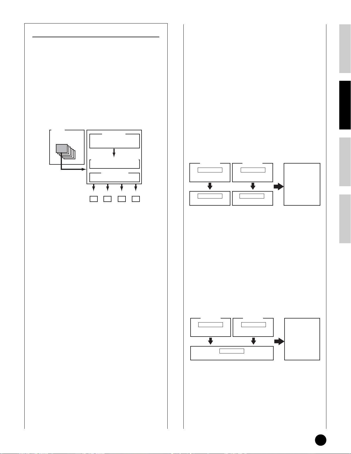
Control Sets (Voice Common Edit [F4])
Keyboard aftertouch, the controllers and some of the
sliders on the front panel can be assigned to control
various parameters other than the ones set as
defaults, as explained on page 53. For example, the
Modulation wheel could be assigned to control filter
resonance, while aftertouch could be used to apply
vibrato. This provides enormous flexibility in
controlling parameters and setting up the controllers
to suit the kind of sound being played.
These controller assignments are known as Control
Sets. As the following illustration shows, you can
assign up to six different Control Sets per Voice.
Voice
Control sets
1-6
Source
Controller
PB, MW, etc.
■ Using one source to control several
destinations
By creating Control Sets, you can change sounds in a
variety of ways.
For example, set the Src (Source) parameter of
Control Set 1 to MW (Modulation Wheel) and the
Dest (Destination) parameter to ELFO-PM (Element
LFO Pitch Modulation Depth). Then set the Src
parameter of Control Set 2 also to MW, but set the
Dest parameter to ELM PAN (Element Pan). You
will also need to specify the Element to be controlled
and also the depth (amount) of control.
In this example, when you move the Modulation
Wheel upward, the amount of Pitch Modulation
increases accordingly, and the Element is panned
from left to right. In this way, you can have the
sound change in several different ways, simply by
adjusting a single controller.
Basics SectionQuick GuideReferenceAppendix
Destination
Control Parameters
Depth
Depth of control
ON/OFF ON/OFF ON/OFF ON/OFF
1
Elements
234
Within each Control Set, the controller is known as
the Source (Src) and the parameter controlled by the
Source is known as the Destination (Dest). There
are various Dest parameters available; some will
apply to the Voice as a whole, while some will be
specific to each of its Elements. Details are given in
the Controls List of the separate Data List.
n Details about the available Dest parameter settings
are given in the Destination Parameter List of the
separate Data List.
n The Element Switches (Voice Common Edit [F4]
Ref. #117) will be disabled if the Dest parameter
setting is not specified for the Elements (i.e., to
settings 00 to 33).
n Elements ON/OFF switch is available only when a
Normal Voice is selected.
SET 1
Src
MW
(Modulation Wheel)
Dest
ELFO-PM
SET 2
Src
MW
(Modulation Wheel)
Dest
ELM PAN
Moving the
Modulation Wheel
changes both the
amount of Pitch
Modulation and
the pan position.
■ Using several sources to control one
destination
Continuing from the example above, now create
another Control Set where Src is set to FC (Foot
Controller) and Dest is set to ELFO-PM (Element
LFO Pitch Modulation Depth). Again, specify the
Element to be controlled and also the depth of
control.
Doing this assigns Pitch Modulation to both the
Modulation wheel and Foot Controller. In this way,
you can assign several different Src controllers to a
single Dest parameter.
SET 1
Src
MW
(Modulation Wheel)
ELFO-PM
Dest
SET 3
Src
FC
(Foot Controller)
You can control
the pitch
modulation effect
using either of
Modulation
Wheel (MW) and
Foot Controller
(FC).
By assigning all six Control Sets, you will have a
stunning degree of real-time control over the
synthesizer’s sounds.
Using Controllers
55
Page 56
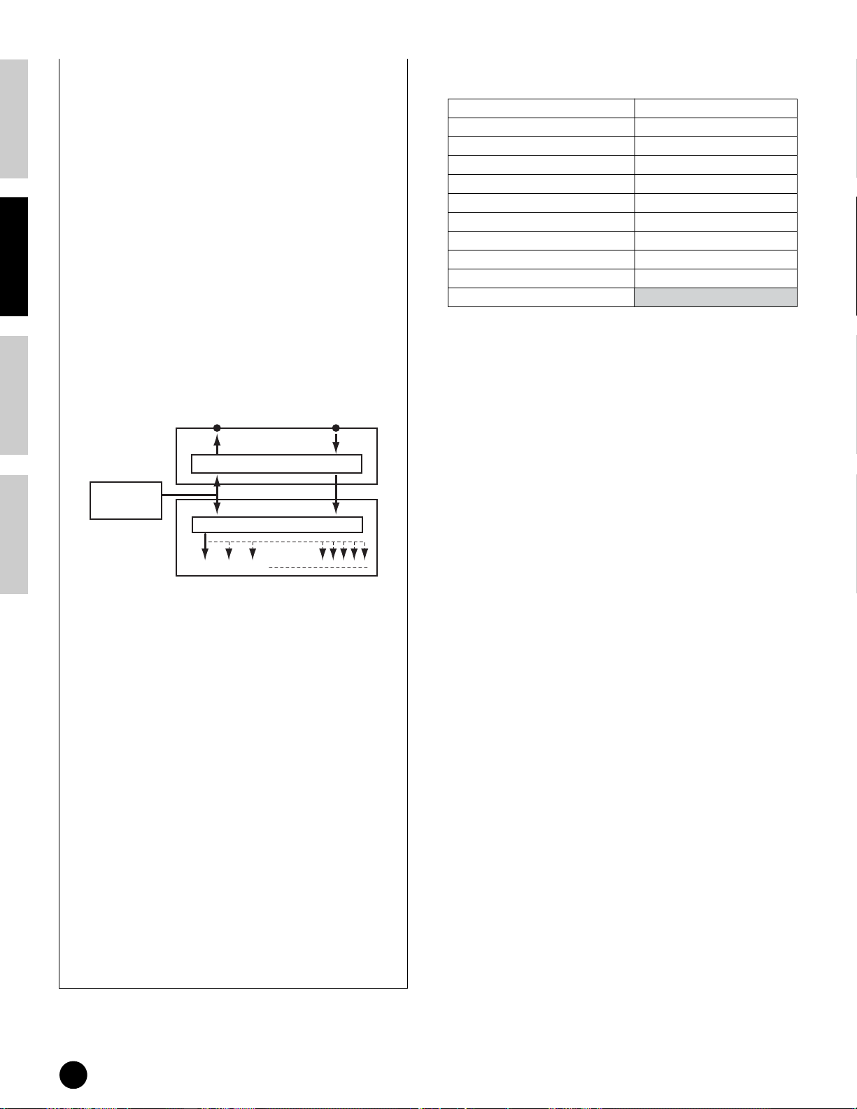
Basics Section Quick Guide Reference Appendix
■ Control Sets and External MIDI Control
Primary control number and function
In a Control Set, the controllers are assigned to the
internal parameters of the synthesizer. However,
some controllers were originally designed for a
particular purpose, and send pre-defined MIDI
Control Change messages when used, regardless of
their Control Set allocations within the synthesizer.
For example, the Pitch Bend Wheel, Modulation
Wheel and keyboard aftertouch were originally
designed to control pitch bend, modulation and
aftertouch. Therefore, when you use these
controllers, pitch bend, modulation and aftertouch
information is always sent to the MIDI Out.
Let’s say the Pan parameter is assigned to the Pitch
Bend Wheel in a Control Set. Now, when you move
the Pitch Bend Wheel, the internal tone generator of
the synthesizer will pan the sound; however, at the
same time, the original pre-defined Pitch Bend
messages will still be sent to the MIDI Out.
\
MIDI
Pitch Bend
Wheel
Tone Generator
OUT IN
MIDI Control
Controller Set
MW/AC1/FC (Variable control) FS (on/off switch)
7 Volume 64 Hold 1 (Sustain)
10 Pan 65 Portamento Switch
11 Expression 66 Sostenuto
71 Harmonic Contents (Resonance) 96 Arpeggio Switch
72 Release Time 97 Arpeggio Hold
73 Attack Time 98 PLAY/STOP
74 Brightness 99 Program Change INC
75 Decay Time 100 Program Change DEC
91 Reverb Send Level 101 Octave Reset
93 Chorus Send Level
See page 119
LFO1Pitch PAN
The controllers can also send MIDI Control Change
messages to control the parameters of external MIDI
devices. These assignments can be set in the Utility
Mode.
n Since Pitch Bend Wheel, Modulation Wheel and
keyboard aftertouch are pre-defined with specific
MIDI controls, other MIDI Control Change
numbers cannot be assigned to them.
You can also set up a controller such that it sends
one kind of Control message to the synthesizer’s
internal tone generator yet another kind to the MIDI
Out.
For example, in a Control Set you could assign
resonance to Assignable 1 Slider. Then, in the
Utility Mode, you could assign Control Number 1
(Modulation) to the same controller. Now, when
you use the controller, resonance will be applied to
the sound of the internal tone generator; however, at
the same time, modulation information will be sent
to the external MIDI device connected to the MIDI
Out.
56
Using Controllers
Page 57

Remote Control for external sequencer
The Remote Control function lets you use the hardware controls on the panel of the S90 to control fundamental
operations on the sequencing software of your computer. You can mute your tracks, control the sequencer transport
(Play/Stop), mix both MIDI and audio tracks (up to 16) with the S90’s control sliders, pan the tracks, control EQ,
and tweak effect sends — all without ever touching the mouse. Not only is this a more convenient and efficient way
to work — since it gives you dedicated controls for the functions you use the most — it also (with the control sliders)
gives you finer control over crucial level parameters. If you’ve ever used a mixing console or a hardware sequencer,
you’ll love being able to finally control your sequencing software with buttons and sliders.
Basics SectionQuick GuideReferenceAppendix
Setting Up
Before you can use the Remote Control function, you’ll
need to set up the system as described below.
1 Connect your computer to
the S90 via USB cable.
See page 17.
2 Install the setup file.
Install the USB MIDI driver and the setup file for the
sequence software (contained in the included CDROM) to your computer. For details on how to install,
see the separate Installation Guide.
3 Select the template for
your particular sequence
software in the Utility mode
2 Call up the OTHER display in the MIDI menu
→→
([F5] →→
3 Move the cursor to the MIDI IN/OUT
parameter and set to USB.
4 Call up the REMOTE display in the CTLASN
menu ([F4] →→
5 Select the Template type, then press the
[ENTER] button.
[SF4]).
→→
[SF4]).
on the S90.
1 Enter the Utility mode.
UTILITY
CARD
SEQ PLAY
Remote Control for external sequencer
57
Page 58

Basics Section Quick Guide Reference Appendix
Using the Remote
Control function
3 Control the level of selected track of the
sequencer by using the Control sliders
(page 59).
1 Turn the Remote Control
function on by pressing the
[REMOTE CONTROL] button so
that its lamp flashes.
REMOTE
CONTROL
2 Operate the Control sliders
or the buttons on the S90’s
panel as required.
1 Select a track on your computer’s sequencer
from the S90.
CONTROL
FUNCTION
MASTER
VOLUME
PAN
CUTOFF
ASSIGN A
MEQ LOW
VOLUME 1
ZONE 1
CS 1
REVERB
RESONANCE
ASSIGN B
MEQ LOW MID
VOLUME 2
ZONE 2
CS 2
CHORUS
ATTACK
ASSIGN 1
MEQ HI MID
VOLUME 3
ZONE 3
CS 3
TEMPO
RELEASE
ASSIGN 2
MEQ HIGH
VOLUME 4
ZONE 4
CS 4
4 Control the transport functions on the
sequencer.
The operations below can be used to control Play,
Stop, Forward and Rewind on the computer
sequence software.
PLAY/STOP
EFFECT
BYPASS
PLAY/
STOP
ARPEGGIO
The [1]~[16] buttons correspond to the respective
numbered tracks on your computer’s sequence
software.
1 2 3 4 5 6 7 8
ELEMENT / PERF.PART / ZONE
9 10 11 12 13 14 15 16
TRACK
SELECT
MUTE
SOLO
2 Turn the track of the sequencer on or off
(mute).
The [1]~[16] buttons correspond to the respective
numbered tracks on your computer’s sequence
software.
1 2 3 4 5 6 7 8
ELEMENT / PERF.PART / ZONE
9 10 11 12 13 14 15 16
TRACK
SELECT
MUTE
SOLO
FORWARD/REWIND
(CHAIN display in Sequence Play mode)
UTILITY
CARD
SEQ PLAY
F4
58
Remote Control for external sequencer
Page 59
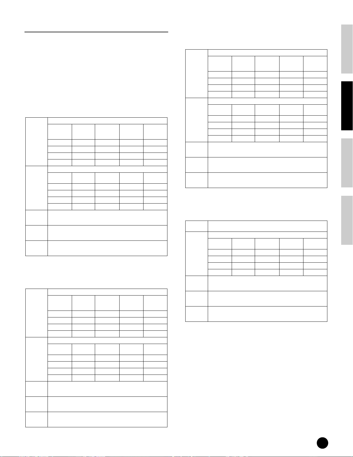
Remote Control Assignments
Functions to be controlled by the S90 differ depending
on the software you use. When the appropriate
template is selected, the following functions on the
corresponding software can be controlled.
n For certain software programs, it may be necessary to
install the setting file in the included CD-ROM.
Logic Audio Platinum Ver5
When the template is set to “Logic,” the following
functions can be controlled by the S90.
These control the track selected via the NUMBER [1] - [16] buttons.
Set via
[CONTROL
FUNCTION]
Each
parameters
VOLUME
(5th row)
SEQ
TRANS-
PORT
TRACK
MUTE
TRACK
SELECT
1st row PAN SEND1 SEND2 SEND3
2nd row PAN EQ1 Freq EQ1 Gain EQ1 Q
3rd row PAN EQ2 Freq EQ2 Gain EQ2 Q
4th row PAN EQ3 Freq EQ3 Gain EQ3 Q
These control the four tracks selected via the NUMBER [1] - [16] buttons.
Selected
tracks
1 ~ 4 VOLUME 1 VOLUME 2 VOLUME 3 VOLUME 4
5 ~ 8 VOLUME 5 VOLUME 6 VOLUME 7 VOLUME 8
9 ~ 12 VOLUME 9 VOLUME 10 VOLUME 11 VOLUME 12
13 ~ 16
These control PLAY, STOP, G, H of the computer sequence
software.
When the [MUTE] button on the S90 is turned on, the NUMBER [1] [16] buttons control the track mute settings of the computer sequence
software.
When the [TRACK SELECT] button on the S90 is turned on, the
NUMBER [1] - [16] buttons select the track of the computer sequence
software.
Cubase VST/32, Cubase VST 5.1r1, SQ01
When the template is set to “Cubase/SQ01” the
following functions can be controlled by the S90.
These control the track selected via the NUMBER [1] - [16] buttons.
Set via
[CONTROL
FUNCTION]
Each
parameters
VOLUME
(5th row)
SEQ
TRANS-
PORT
TRACK
MUTE
TRACK
SELECT
1st row PAN SEND1 SEND2 SEND3
2nd row PAN EQLo Freq EQLo Gain EQLo Q
3rd row PAN EQMidLo Fre EQMidLo Gai EQMidLo Q
4th row PAN EQHi Freq EQ3Hi Gain EQ3Hi Q
These control the four tracks selected via the NUMBER [1] - [16] buttons.
Selected
tracks
1 ~ 4 VOLUME 1 VOLUME 2 VOLUME 3 VOLUME 4
5 ~ 8 VOLUME 5 VOLUME 6 VOLUME 7 VOLUME 8
9 ~ 12 VOLUME 9 VOLUME 10 VOLUME 11 VOLUME 12
13 ~ 16
These control PLAY, STOP, G, H of the computer sequence
software.
When the [MUTE] button on the S90 is turned on, the NUMBER [1] [16] buttons control the track mute settings of the computer sequence
software.
When the [TRACK SELECT] button on the S90 is turned on, the
NUMBER [1] - [16] buttons select the track of the computer sequence
software.
CS1 CS2 CS2 CS4
CS1 CS2 CS3 CS4
VOLUME 13
VOLUME 13
VOLUME 14 VOLUME 15 VOLUME 16
CS1 CS2 CS2 CS4
CS1 CS2 CS3 CS4
VOLUME 14 VOLUME 15 VOLUME 16
SONAR2/Cakewalk ProAudio Ver9.0
When the template is set to “SONAR,” the following
functions can be controlled by the S90.
These control the track selected via the NUMBER [1] - [16] buttons.
Set via
Each
parameters
VOLUME
(5th row)
SEQ
TRANS-
PORT
TRACK
MUTE
TRACK
SELECT
[CONTROL
FUNCTION]
1st row PAN SEND1 SEND2 SEND3
2nd row --- --- --- ---
3rd row --- --- --- --4th row --- --- --- ---
These control the four tracks selected via the NUMBER [1] - [16] buttons.
Selected
tracks
1 ~ 4 VOLUME 1 VOLUME 2 VOLUME 3 VOLUME 4
5 ~ 8 VOLUME 5 VOLUME 6 VOLUME 7 VOLUME 8
9 ~ 12 VOLUME 9 VOLUME 10 VOLUME 11 VOLUME 12
13 ~ 16
Control PLAY, STOP, G, H of the computer sequence software.
When the [MUTE] button on the S90 is turned on, the NUMBER [1] [16] buttons control the track mute settings of the computer sequence
software.
When the [TRACK SELECT] buttons on the S90 is turned on, the
NUMBER [1] - [16] buttons select the track of the computer sequence
software.
CS1 CS2 CS2 CS4
CS1 CS2 CS3 CS4
VOLUME 13
VOLUME 14 VOLUME 15 VOLUME 16
Pro Tools V5.0
When the template is set to “ProTools,” the following
functions can be controlled by the S90.
Each
parameters
VOLUME
(5th row)
TRANS-
PORT
TRACK
MUTE
TRACK
SELECT
Not available.
These control the four tracks selected via the NUMBER [1] - [16] buttons.
Selected
tracks
1 ~ 4 VOLUME 1 VOLUME 2 VOLUME 3 VOLUME 4
5 ~ 8 VOLUME 5 VOLUME 6 VOLUME 7 VOLUME 8
9 ~ 12 VOLUME 9 VOLUME 10 VOLUME 11 VOLUME 12
13 ~ 16
SEQ
These control PLAY, STOP, G, H of the computer sequence
software.
When the [MUTE] button on the S90 is turned on, the NUMBER [1] [16] buttons control the track mute settings of the computer sequence
software.
When the [TRACK SELECT] button on the S90 is turned on, the
NUMBER [1] - [16] buttons select the track of the computer sequence
software.
CS1 CS2 CS3 CS4
VOLUME 13
VOLUME14 VOLUME 15 VOLUME 16
Basics SectionQuick GuideReferenceAppendix
Remote Control for external sequencer
59
Page 60

Basics Section Quick Guide Reference Appendix
MODE
VOICE
PERFORM
MASTER
JOBEDIT
COMPARE
STORE
VOICE
PERFORM
MASTER
UTILITY
CARD
SEQ PLAY
ARPEGGIO
EFFECT
BYPASS
PLAY/
STOP
MODE
Voice Edit
The following procedure shows you the fundamentals in creating and editing Voices.
Of course, this is just one example; you are free to set any parameters in any way you like. Details about each
parameter are given in the Reference section of this manual (page 98).
n All parameter settings are stored along with the Voice itself.
1
In Voice Play mode, select the Voice you wish to edit.
2
Enter the Voice Edit mode.
3
Set the common parameters
● Set the parameters common to all Elements in the
Voice (volume, pitch, tone, etc.) You can also set
parameters related to Arpeggio, Controllers,
Effects, and so on.
4
Set the element parameters
● From the OSC (Oscillator) screens, select the
Waves used by the Elements in the Voice, as well
as the volume, pan, note range and other basic
parameters.
● From the PITCH screens, set the tuning and other
pitch-related parameters used by the Elements.
Also set the PEG (Pitch Envelope Generator)
parameters as necessary.
● From the FILTER screens, adjust the parameters of
the filters used by the Elements. Also set the FEG
(Filter Envelope Generator) parameters as
necessary.
● From the AMP (Amplitude) screens, set the volume
and other output level-related parameters used by
the Elements. Also set the AEG (Amplitude
Envelope Generator) parameters as necessary.
● From the LFO (Low Frequency Oscillator) screens,
set the modulation-related parameters used by the
Elements.
● From the EQ (Equalizer) screens, adjust the
sounds as necessary.
1 Selecting a Voice to Edit
Enter the Voice Play mode by pressing a [VOICE]
button.
Select the Voice Number of the Voice you wish to edit
(page 36).
n When you’re creating a Voice by editing an existing one,
it helps to select a Voice with a sound that’s relatively
similar to the one you intend to create. In this way, you
can avoid having to make large changes and many
parameter edits — allowing you to create a Voice quickly
and easily. If you are creating a Voice from scratch, use
the convenient Initialize function (in the Voice Job
mode) to initialize a Voice in internal user memory. For
details, see page 70.
2 Entering the Voice Edit Mode
All Voice creation and editing is carried out in Voice
Edit Mode.
To enter the Voice Edit mode, press the [EDIT] button
while in the Voice Play mode.
60
5
Set the effect parameters.
6
Store the edited Voice.
Voice Edit
Page 61

Common Edit and Editing Individual
Elements
Switching Elements (or Keys)
On/Off (Mute)
Voices can consist of up to four Elements (page 26).
Use Common Edit to edit the settings common to all
four Elements.
Switching Between Screens and
Entering Settings
1Select the menu you wish to edit by pressing
the [F1] - [F6] and [SF1] - [SF5] buttons.
2Select the desired parameter by using
[ ▲ ▼ EF] buttons.
Basics SectionQuick GuideReferenceAppendix
To edit parameters common to all four elements, press
the [DRUM KITS] button (which serves as a
“COMMON” button here).
DRUM KITS
FAVORITES
COMMON
To edit parameters of the individual elements, select
the desired element with the corresponding NUMBER
button ([1] - [4]).
1 2 3 4
Element selection
ELEMENT / PERF.PART / ZONE
9 10 11 12
Element mute setting
You can mute other elements (those you aren’t
editing and don’t wish to hear) by using the
NUMBER [9] - [12] buttons (Normal Voice only).
Muted elements are indicated by lit buttons; the
indicator of the button corresponding to the muted
element lights.
3Use the [INC/YES] and [DEC/NO] buttons to
set each parameter value.
n For details about the Edit indicator, see page 39.
Compare Function
Use this to listen to the difference between the
Voice/Performance with your edited settings and the
same Voice/Performance prior to editing.
1 Press the [COMPARE (EDIT)] button while in
Edit mode. The EDIT LED will flash and the
settings prior to editing will temporarily be
reinstated for comparison purposes.
(The indicator is shown at the top of the
display in place of the indicator.)
n
While the Compare function is enabled, the [DEC/NO]
and [INC/YES] buttons cannot be used for editing.
2 Press the [EDIT] button again to disable the
Compare function and restore your recently
edited settings.
To solo an element
1 2 3 4 5 6 7 8
ELEMENT / PERF.PART / ZONE
9 10 11 12 13 14 15 16
Simultaneously hold down the [MUTE] button and
press one of the NUMBER buttons [9] to [12] to solo
the corresponding element.
Once you’ve selected an element for soloing, the
[MUTE] button’s lamp flashes, indicating the Solo
function is active. While Solo is active, you can
change the soloed element simply by pressing the
corresponding NUMBER button [9] to [12].
To exit from the Solo function, press the [MUTE]
button again.
TRACK
SELECT
MUTE
SOLO
n The Compare function is also available in the
Performance Edit mode.
Voice Edit
61
Page 62

Basics Section Quick Guide Reference Appendix
3 Set the Common
Parameters
Each Voice consists of up to four Elements. Here, the
parameters common to all Elements are explained.
●
GENERAL [F1]
For setting general parameters in Common Edit, such
as the Voice Name.
●
OUTPUT [F2]
For setting the Voice output parameters such as the
output level (volume) and pan position.
●
ARP [F3]
By setting these parameters, you can control how the
Voice is arpeggiated (page 45).
●
CTL SET [F4]
For assigning various functions to the controllers on
the front/rear panel. For example, you can assign
parameters to the Pitch Bend Wheel and a Foot
Controller so that you can change the tone of the Voice
in real time (page 55).
●
LFO [F5]
For setting the LFO parameters. The LFO uses a low
frequency waveform to vary the pitch/filter/amplitude
characteristics, and can be used to create vibrato, wah,
tremolo and other effect.
●
EFFECT [F6]
For setting the Effects parameters for the Voice. There
are two Insertion Effects plus two System Effects
(Reverb and Chorus).
4 Set the Element Parameters
Element Edit Process
PEG FEG AEG
Element
1-4
AMPFILTERPITCH
OSC
LFO
● OSC (Oscillator) [F1]
You can set the various parameters controlling the
waveforms on which the Voice is based. You can select
the Wave used for the Element, the volume and note
range of each Element and so on.
ElementSw (Element Switch)
Determines whether each Element sounds or not.
WaveNo. (Wave Number)
Select the Wave for each Element.
NoteLimit (Note Limit Low/High)
VelocityLimit (Velocity Limit Low/High)
Set the note range for each Element (the range of notes
on the keyboard over which the Element will sound)
and also the velocity response (the range of note
velocities within which the Element will sound). You
can assign different settings for each Element. With
these parameters, you can layer Elements and control
their output.
For example, you could set one Element to sound in an
upper range of the keyboard, and another Element to
sound in a lower range. Thus, even within the same
Voice, you can have two different sounds for different
areas of the keyboard or you can make the two Element
ranges overlap so that their sounds are layered over a
set range.
Furthermore, you can set each Element to respond to
different velocity ranges so that one Element sounds
for lower note velocities, whereas another Element
sounds for higher note velocities.
Effect
62
Voice Edit
Element 3
Velocity
n In the Performance mode, similar settings can be
Element 1
C-2 G8
assigned for each Part (Ref. #42, 43).
Element 2
Element 4
Page 63

● PITCH [F2]
You can set the basic pitch parameters for each
Element. You can detune Elements, apply Pitch
Scaling and so on. Also, by setting the PEG (Pitch
Envelope Generator), you can control how the pitch
changes over time.
PEG (Pitch Envelope Generator) [F2] →→
→→
[SF3]
Using the PEG, you can control the transition in pitch
from the moment a note is pressed on the keyboard to
the point at which it is released. As illustrated below,
the Pitch Envelope consists of five Time (transition
speed) parameters and five Level (pitch) parameters.
This is useful for creating automatic changes in pitch.
Furthermore, different PEG parameters can be set for
each Element.
● FILTER [F3]
You can use the filter to change the tonal
characteristics of each Element, by adjusting overtones
(harmonic tones) included in the waveform of the
Element.
Basics SectionQuick GuideReferenceAppendix
Cutoff Frequency and Resonance
Filters work by allowing the portion of the signal lower
than a given frequency to pass, and cutting the portion
of the signal above that frequency. This frequency is
referred to as the cutoff frequency. You can produce a
relatively bright or darker sound by setting the cutoff.
Resonance, on the other hand, boosts the level of the
signal at the cutoff frequency. By emphasizing the
overtones in this area, this can produce a distinctive
“peaky” tone, making the sound brighter and harder.
The full names of the available parameters are shown
in the chart below, as they appear in the display.
HOLD ATK DCY1 DCY2 REL DEPTH
TIME Hold time Attack time
LEVEL Hold level Attack level
Attack
Attack
Time
Level
Decay1
Pitch
Hold Level
0
Hold
Time
Time
Decay 1
Decay 1
level
Decay1
Level
time
Decay2
Time
Decay 2
time
Decay 2
(Sustain)
level
Decay2
(Sustain)
Level
Release
Release
Key off
time
level
Release
Time
---
Depth
Release
Level
Time
Level
Cutoff frequency
Frequency (pitch)
These frequencies are
“passed” by the filter.
Level
Resonance
Frequency (pitch)
Cutoff frequency
About the Filter types
The Low Pass Filter is shown in the illustration above —
however, the S90 features other Filter types as well.
LPF24D (Low Pass Filter 24dB/oct Digital)
A 4-pole (-24db/oct) dynamic LPF with a strong resonance.
Resonance
Voice Edit
63
Page 64

Basics Section Quick Guide Reference Appendix
LPF24A (Lo
w Pass Filter 24dB/oct Analog)
A 4-pole (-24db/oct) dynamic LPF with a character similar
to those found on analog synthesizers
BPF12D (Band Pass Filter 12dB/oct Digital)
Level
Range passed
Resonance
LPF18 (Lo
w Pass Filter18dB/oct)
A 3-pole (-18db/oct) dynamic LPF.
LPF18s (Lo
w Pass Filter [18dB/oct Staggered)
Also a 3-pole (-18db/oct) dynamic LPF, but with a
shallower frequency curve.
Resonance
LPF18
LPF18S
LPF12 (Lo
w Pass Filter12dB/oct)
A 2-pole (-12db/oct) dynamic LPF, designed to be used in
combination with an HPF (High Pass Filter).
Resonance
-12db/oct
Frequency
Cutoff range
Cutoff range
BPF12s (Band Pass Filter 12dB/oct Staggered)
Basically same as BPF12D, but with a shallower frequency
curve.
BPF6 (Band P
Level
Cutoff range Cutoff range
ass Filter 6dB/oct)
Range passed
-6db/oct
Frequency
BPFw (Band Pass Filter Wide)
Also the combination of –12dB/oct HPF and LPF, but
allows a wider frequency band.
Level
Range passed
LPF6 (Low Pass Filter 6dB/oct)
A 1-pole (-6db/oct) dynamic LPF with no resonance, designed
to be used in combination with an HPF (High Pass Filter).
HPF24D (High Pass Filter 24dB/oct Digital)
A 4-pole (-24db/oct) dynamic HPF with strong resonance.
Resonance
HPF12 (High P
ass Filter 12dB/oct)
A 2-pole (-12db/oct) dynamic HPF.
width can be
increased
Cutoff range Cutoff range
BEF12 (
Band Elimination Filter 12dB/oct)
Frequency
BEF6 (Band Elimination Filter 6dB/oct)
Level
Range passed
Cutoff range
Frequency
Range passedCenter frequency
Dual LPF
A combination of two sets of –12dB/oct LPF in parallel.
Level
The cutoff frequency
can be set directly on
the display.
Distance
Frequency
64
Resonance
Voice Edit
Page 65

Dual HPF
A combination of two sets of –12dB/oct HPF in parallel.
Level
Distance
HPF12 (High P
ass Filter 12dB/oct)+ BPF6 (Band Pass
Filter)
A combination of a HPF and BPF.
Level
Basics SectionQuick GuideReferenceAppendix
The cutoff frequency can be
set directly on the display.
Frequency
Dual BPF
A combination of two sets of –6dB/oct BPF in parallel.
Level
The cutoff frequency can be
set directly on the display.
Distance
Frequency
Dual BEF
A combination of two sets of –6dB/oct BEF in parallel.
Level
Frequency
Distance
The cutoff frequency can be
set directly on the display.
Frequency
thru
The filters are bypassed and the entire signal is unaffected.
n Filter parameters are also available in Part editing.
You can also set the Filter Envelope Generator (FEG) for
time variance of how the filter works, which results in a
dynamic change in tonal characteristics. Here, we’ll
show you how the FEG works.
FEG (Filter Envelope Generator) [F3] →→
→→
[SF3]
Using the FEG, you can control the transition in tone
from the moment a note is pressed on the keyboard to
the point at which it is released. As illustrated at right,
the Filter Envelope consists of five Time (transition
speed) parameters and five Level parameters (for the
amount of filtering). When you press a note on the
keyboard, the cutoff frequency will change according to
these envelope settings. This is useful for creating
automatic wah effects, for example. Furthermore,
different FEG parameters can be set for each Element.
LPF12 (Lo
w Pass Filter 12dB/oct)+ HPF12 (High Pass
Filter)
A combination of a LPF and HPF.
Level
Distance
The cutoff frequency can be
set directly on the display.
Frequency
LPF12 (Low Pass Filter 12dB/oct)+ BPF6 (Band Pass Filter)
A combination of a LPF and BPF.
Level
Frequency
The full names of the available parameters are shown
in the chart below, as they appear in the display.
HOLD ATK DCY1 DCY2 REL DEPTH
TIME Hold time Attack time
Attack
Level
Attack
Time
Attack
level
LEVEL Hold level
Cutoff
Frequency
Hold Level
0
Hold
Time
Decay1
Level
Decay1
Time
Decay 1
Decay 1
Decay2
time
level
Time
Decay 2
Decay 2
(Sustain)
Decay2
(Sustain)
Level
time
level
Key off
Release
time
Release
level
Release
Time
Release
Level
---
Depth
Time
Voice Edit
65
Page 66

Basics Section Quick Guide Reference Appendix
● AMP (Amplitude) [F4]
You can set the volume of each Element after the OSC
(Oscillator), PITCH and FILTER parameters have been
applied, as well as the final overall volume of the signal
sent to the outputs.
The signal of each Element is sent at the specified
volume to the next Effect section.
Also, by setting the AEG (Amplitude Envelope
Generator), you can control how the volume changes
over time.
●
EQ (Equalizer) [F6]
Adjusting the sound can serve to draw out the special
characteristics of the sound and help achieve the
proper balance among the Elements (Ref. #210-215).
5
Set the Effect Parameters
For an application example showing how to use the
effect, see page 67.
AEG (Amplitude Envelope Generator) [F4] →→
→→
[SF3]
Using the AEG, you can control the transition in
volume from the moment a note is pressed on the
keyboard to the point at which it is released. As
illustrated below, the Amplitude Envelope consists of
four Time (transition speed) parameters and three
Level parameters (for the amount of filtering). When
you press a note on the keyboard, the volume will
change according to these envelope settings.
Furthermore, different AEG parameters can be set for
each Element.
The full names of the available parameters are shown
in the chart below, as they appear in the display.
INIT ATK DCY1 DCY2 REL DEPTH
Time
Decay1
Level
Decay 1
time
Decay 1
level
Decay2
Time
TIME --- Attack time
LEVEL Initial level ---
Level
●
LFO (Low Frequency Oscillator) [F5]
Attack
Level
Init
Level
0
Attack
Decay1
Time
Decay2
(Sustain)
Level
Decay 2
time
Decay2
(Sustain)
level
Key off
Release
time
---
Release
Time
Release
Level
---
Time
As its name suggests, the LFO creates waveforms of a
low frequency.
These waveforms can be used to vary the pitch, filter or
amplitude of each Element to create effects such as
vibrato, wah and tremolo. LFO can be set
independently for each Element; it can also be set
globally for all Elements (Ref. #159-174).
6 Storing Edited Voices
Up to 128 new/edited Normal Voices and 16 new/
edited Drum Voices can be stored to internal user
memory.
Voice
Store
Normal Voice
USER (US)
1-128
Drum Voice
USER DRUM (USDR)
1-16
When storing a Voice, any existing data at the storage
location will be lost. You should always back up
important data to Memory card or computer.
n For details about storing Voices, see page 73.
About Board Custom Voice Editing
You can edit Board Custom voices of the Plug-in
Board by using the Editor software included with
the board.
n Select the Part Number of the Editor software to
“1” when using the software with the Voice mode.
Also make sure to match the basic MIDI receive
channel of the S90 (Ref. #176) to the MIDI
channel of the Editor software.
The original Board Custom voices you’ve edited can
be saved and controlled from the computer.
Make sure to save the edited data to a memory card,
since any edited data in the DRAM of the Plug-in
board will be lost when you turn off the power on
the S90 (page 82).
n For details about how to use the Editor software
included with the Plug-in board, refer to the Online
help of the Voice Editor.
n Editing the above parameters may or may not have
much effect on the sound, depending on the
particular Plug-in board you’ve installed.
66
Voice Edit
Page 67

Using Effects
In the final stage of programing, you can set the effects parameters to further change the sound’s character.
Basics SectionQuick GuideReferenceAppendix
Effect structure
The S90’s effect processing features the following
effect units.
■ System Effects (Reverb, Chorus, Variation)
System Effects are applied to the overall sound,
whether it be a voice, an entire performance setup, a
song, etc. With System effects, the sound of each part
is sent to the effect according to the effect Send Level
for each part. The processed sound (referred to as
“wet”) is sent back to the mixer, according to the
Return Level, and output — after being mixed with the
unprocessed “dry” sound. This arrangement lets you
prepare an optimum balance of the effect sound and
the original sound of the parts.
Reverb
The Reverb effects add a warm ambience to the sound,
simulating the complex reflections of actual
performance spaces, such as a concert hall or a small
club. A total of 12 different Reverb types are available.
Chorus
The Chorus effects use modulation to create a rich
ensemble sound — as if one part were being played by
several instruments simultaneously. A total of 25
different Chorus types are available.
Variation
The Variation effects provide a wide variety of sound
transformations and enhancements. A total of 25
different Variation types are available. Variation is not
available in the Voice mode.
■ Insertion Effects (1, 2)
Insertion effects can be applied individually to each
part. Insertion effects are mainly used to directly
process a single part. The depth of the effect is
adjusted by setting the dry/wet balance. Since an
Insertion effect can only be applied to one particular
part, it should be used for sounds you want to
drastically change. You can also set the balance so that
only the effect sound is heard, by setting Wet to 100%.
The S90 features two Insertion effect systems — one
with a total of 104 internal effect types and the other
with 25.
■ Master Equalizer
Usually an equalizer is used to correct the sound
output from amps or speakers to match the special
character of the room. The sound is divided into
several frequency bands, then by raising or lowering
the level for each band, the correction is made.
Adjusting the sound you play according to the genre—
classical music being more refined, pops music more
crisp, and rock music more dynamic—can also serve to
draw out the special characteristics of the music and
make your performance more enjoyable.
The S90 possesses a high grade five-band digital
equalizer function. The four sliders can be used to
adjust the gain of the four bands (among five).
Example of Effect Settings
Here we’ll show an example of editing effect settings
in the Voice Edit mode (page 60). In this example,
we’ll change the Insertion1 setting of the Voice Or:
BreathPipe (PRE1: E13) from Thru to FLANGER
(a jet-like sound).
1 Select the Voice Number of the Voice you wish to
edit (Here, Or: BreathPipe=PRE1: E13), then
enter the Voice Edit mode (pages 36 and 60).
2 Press the [COMMON] button to select the
Common Edit display (page 61).
3 Press the [F6]→[SF1] buttons to call up the
CONNECT display.
4 Use the [▲ ▼ EF] button to select the INS1
(INS1 Type) screen.
■ Plug-in Insertion Effects
This is a special effect system, only available when an
effect-type Plug-in Board (page 22) is installed. Plug-in
Board effects are not available in the Voice mode.
Using Effects
67
Page 68
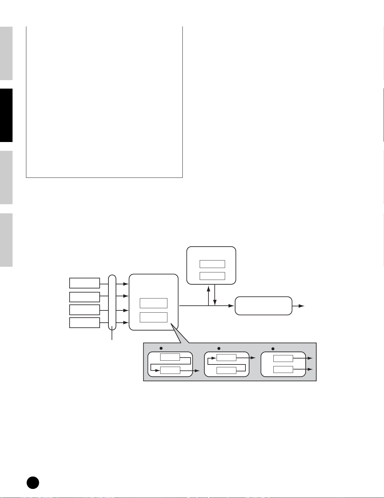
Basics Section Quick Guide Reference Appendix
5 Use the data dial to select “FLG: FLANGER1”
then play the keyboard. Try out other different
Effect Types, referring to the Effect Type List in
the separate Data List.
n You can listen to and compare the difference
between the edited Voice with your edited settings
and the same Voice prior to editing (page 61).
n To bypass effect processing, press the [EFFECT
BYPASS] button (the LED lights).
n In the effect parameter screens ([SF2]-[SF5]), you
can make various detailed parameter settings. You
can scroll through the screens by using the
[EF] buttons. For information on the Effect
Parameters, refer to the separate Data List.
6 If you wish to save your new settings, store the
settings as a single Voice before you leave the
Voice Edit mode. For details about storing Voices,
see page 73.
Effect connection
● In the Voice mode:
Three different Insertion connection types are available, as shown below.
System Effects
Tone Generator
block
Element 1
Element 2
Element 3
Element 4
This determines which Insertion
system, 1 or 2, is applied to
each Element (or to each key
when the Drum voice is
selected). The Insertion effect
can also be bypassed.
Insertion Effects
1
2
1 to 2
1
2
Send Level
n The parallel connection type is not available for Plug-in voices.
Reverb
Chorus
Return Level
You can select the Insertion connection
from the three types shown below.
2 to 1
1
2
Master Equalizer
parallel
Output
1
2
68
Using Effects
Page 69

● In the Performance mode:
The diagram below indicates the internal signal flow when the Vocal Harmony Plug-in Board (PLG100-VH) is
installed to slot 1.
Select the part to which the
Insertion effect is applied from
parts 1-4 and Plug-in parts 2-3.
The connection type depends
on the setting of the Voice
assigned to the selected part.
Tone Generator
block
Parts 1-4,
Plug-in parts 2-3
Insertion Effects
1
2
System Effects
Reverb
Chorus
Variation
Send Level
Return Level
Master Equalizer
Output
Insertion Effect
(Plug-in)
PLG 100-VH
Select the part to which
the Plug-in Insertion
effect is applied from
parts 1-4, Plug-in parts
2-3 and A/D Input part.
A/D
• External audio source
• Microphone sound
n The Vocal Harmony Plug-in Board (PLG100-VH) can be installed only to slot 1. It cannot be installed to slot 2 or 3.
Basics SectionQuick GuideReferenceAppendix
● In the Sequence Play/Mixing mode:
The diagram below indicates the internal signal flow when the Vocal Harmony Plug-in Board (PLG100-VH) is
installed to slot 1 and the Multi part Plug-in Board (PLG-100XG) is installed to slot 3.
Select the part to which the
Tone Generator
block
Part 1~16
Part 17-32 *
(When the Multi-part Plugin board has been installed)
Plug-in Part 2
(When the Single part Plugin board has been installed)
Select the part to which the
Plug-in Insertion effect is
applied.
Insertion effect is applied. The
connection type depends on the
setting of the Voice assigned to
the selected part.
Insertion Effects
1
2
Insertion Effect
(Plug-in)
PLG100-VH
• External audio source
• Microphone sound
A/D
System Effects
Reverb
Chorus
Variation
Send Level
Return Level
Master Equalizer
Output
* Please note that the Insertion Effect, Insertion Effect (Plug-in), and the System Effects cannot be applied to parts 17~32
(using the Multi-part Plug-in board). The signal from parts 17~32 is directly sent to the Master Equalizer.
Using Effects
69
 Loading...