

Page 1

RX-497
Stereo Receiver
Récepteur stéréo
G
OWNER’S MANUAL
MODE D’EMPLOI
BEDIENUNGSANLEITUNG
BRUKSANVISNING
GEBRUIKSAANWIJZING
ИНСТРУКЦИЯ ПО ЭКСПЛУАТАЦИИ
Page 2

CAUTION: READ THIS BEFORE OPERATING YOUR UNIT.
CAUTION: READ THIS BEFORE OPERATING YOUR UNIT.
1 To assure the finest performance, please read this manual
carefully. Keep it in a safe place for future reference.
2 Install this sound system in a well ventilated, cool, dry, clean
place – away from direct sunlight, heat sources, vibration,
dust, moisture, and/or cold. Allow ventilation space of at least
30 cm on the top, 20 cm on the left and right, and 20 cm on
the back of this unit.
3 Locate this unit away from other electrical appliances, motors,
or transformers to avoid humming sounds.
4 Do not expose this unit to sudden temperature changes from
cold to hot, and do not locate this unit in an environment with
high humidity (i.e. a room with a humidifier) to prevent
condensation inside this unit, which may cause an electrical
shock, fire, damage to this unit, and/or personal injury.
5 Avoid installing this unit where foreign objects may fall onto
this unit and/or this unit may be exposed to liquid dripping or
splashing. On the top of this unit, do not place:
– Other components, as they may cause damage and/or
discoloration on the surface of this unit.
– Burning objects (i.e. candles), as they may cause fire,
damage to this unit, and/or personal injury.
– Containers with liquid in them, as they may fall and liquid
may cause electrical shock to the user and/or damage to
this unit.
6 Do not cover this unit with a newspaper, tablecloth, curtain,
etc. in order not to obstruct heat radiation. If the temperature
inside this unit rises, it may cause fire, damage to this unit,
and/or personal injury.
7 Do not plug in this unit to a wall outlet until all connections
are complete.
8 Do not operate this unit upside-down. It may overheat,
possibly causing damage.
9 Do not use force on switches, knobs and/or cords.
10 When disconnecting the power cable from the wall outlet,
grasp the plug; do not pull the cable.
11 Do not clean this unit with chemical solvents; this might
damage the finish. Use a clean, dry cloth.
12 Only voltage specified on this unit must be used. Using this
unit with a higher voltage than specified is dangerous and may
cause fire, damage to this unit, and/or personal injury.
YAMAHA will not be held responsible for any damage
resulting from use of this unit with a voltage other than
specified.
13 To prevent damage by lightning, keep the power cord and
outdoor antennas disconnected from a wall outlet or the unit
during a lightning storm.
14 Do not attempt to modify or fix this unit. Contact qualified
YAMAHA service personnel when any service is needed. The
cabinet should never be opened for any reasons.
15 When not planning to use this unit for long periods of time
(i.e. vacation), disconnect the AC power plug from the wall
outlet.
16 Install this unit near the AC outlet and where the AC power
plug can be reached easily.
17 Be sure to read the “TROUBLESHOOTING” section on
common operating errors before concluding that this unit is
faulty.
18 Before moving this unit, press MASTER ON/OFF to release it
outward to the OFF position, and disconnect the AC power
plug from the wall outlet.
19 VOLTAGE SELECTOR (Asia and General models only)
The VOLTAGE SELECTOR on the rear panel of this unit
must be set for your local main voltage BEFORE plugging
into the AC main supply. Voltages are:
General model .............AC 110/120/220/230–240 V, 50/60 Hz
Asia model ................................ AC 220/230–240 V, 50/60 Hz
\
WARNING
TO REDUCE THE RISK OF FIRE OR ELECTRIC
SHOCK, DO NOT EXPOSE THIS UNIT TO RAIN
OR MOISTURE.
As long as this unit is connected to the AC wall outlet,
it is not disconnected from the AC power source even
if you turn off this unit by MASTER ON/OFF, or
MAIN ZONE ON/OFF and ZONE 2 ON/OFF. In this
state, this unit is designed to consume a very small
quantity of power.
Page 3

CONTENTS
INTRODUCTION
FEATURES............................................................. 2
SUPPLIED ACCESSORIES ................................. 2
CONTROLS AND FUNCTIONS ......................... 3
Front panel ................................................................. 3
Front panel display .................................................... 5
Rear panel .................................................................. 6
Remote control........................................................... 7
Installing batteries in the remote control ................... 9
Using the remote control ........................................... 9
PREPARATION
CONNECTIONS .................................................. 10
Connecting speakers ................................................ 11
Connecting the AM and FM antennas ..................... 12
Connecting the power supply cord .......................... 14
Turning on and off this unit ..................................... 14
BASIC OPERATION
PLAYING AND RECORDING .......................... 15
Playing a source....................................................... 15
Adjusting the tonal quality.......................................16
Recording a source .................................................. 17
Using the sleep timer ............................................... 18
Muting the sound output ..........................................19
FM/AM TUNING ................................................. 20
Automatic tuning ..................................................... 20
Manual tuning.......................................................... 21
Automatic preset tuning........................................... 22
Manual preset tuning ...............................................24
Selecting preset stations........................................... 25
Exchanging preset stations ...................................... 25
RADIO DATA SYSTEM
(EUROPE MODEL ONLY) ............................ 26
Receiving Radio Data System stations .................... 26
Changing the Radio Data System mode .................. 26
PTY SEEK function ................................................ 27
EON function........................................................... 28
ADVANCED OPERATION
ADVANCED SETUP ............................................29
Changing the ADVANCED SETUP menu
parameters ........................................................... 29
Switching the remote control ID ............................. 30
ZONE 2 ..................................................................31
Connecting the Zone 2 components ........................ 31
Controlling Zone 2................................................... 32
REMOTE CONTROL FEATURES ...................33
Control area ............................................................. 33
Controlling other components ................................. 34
Setting remote control codes ...................................35
ADDITIONAL INFORMATION
TROUBLESHOOTING .......................................36
SPECIFICATIONS...............................................39
PREPARATIONINTRODUCTION
OPERATION
BASIC
OPERATION
ADVANCED
INFORMATION
ADDITIONAL
1
English
Page 4
FEATURES
\
FEATURES
Built-in 2-channel power amplifier
◆ Minimum RMS output power
75 W + 75 W (8 Ω), 0.04% THD, 20 Hz to 20 kHz
◆ Highly dynamic power, low impedance drive
capability
Sophisticated AM/FM tuner
◆ 40-station random access preset tuning
◆ Automatic preset tuning
Other features
◆ PURE DIRECT button used to reproduce the purest
source sound
◆ Continuously variable loudness control
◆ Sleep timer
◆ Remote control capability
◆ Zone 2 remote control (sold separately) capability
◆ Zone 2 custom installation facility
◆ Preset station exchanging capability
◆ Radio Data System tuning capability
(Europe model only)
• y indicates a tip for your operation.
• Some operations can be performed by using either the buttons on the front panel of this unit or those on the remote control. In case the
button names differ between this unit and the remote control, the names of the buttons on the remote control are given in parentheses.
• This manual is printed prior to production. Design and specifications are subject to change in part as a result of improvements, etc. In
case of differences between the manual and the product, the product has priority.
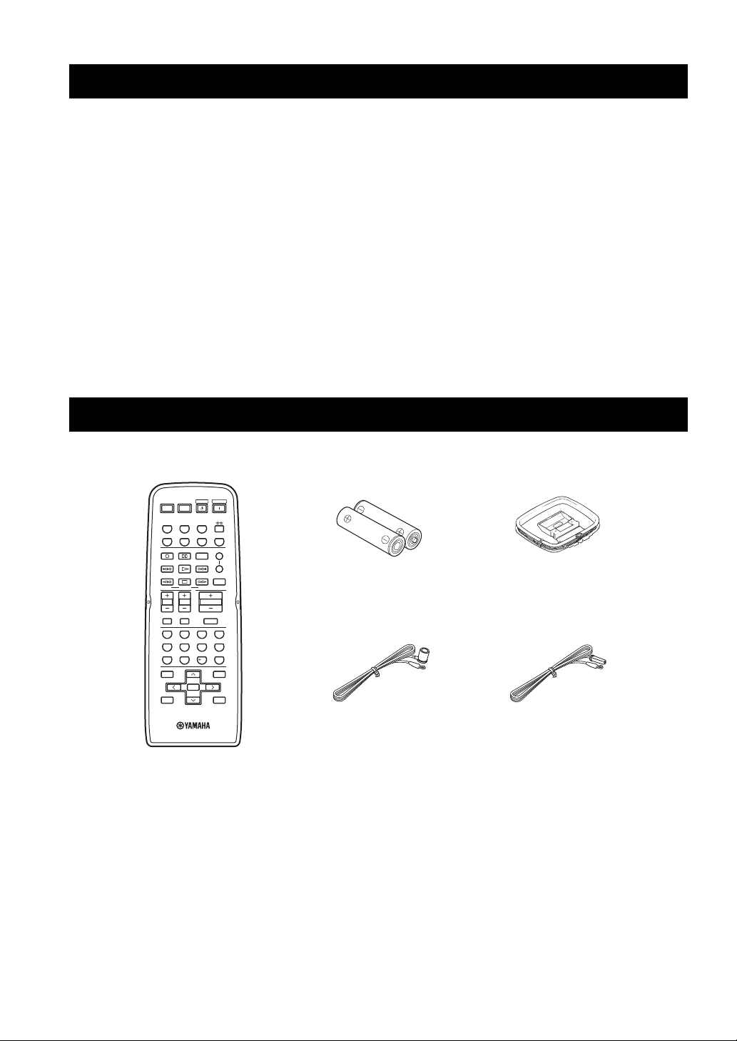
SUPPLIED ACCESSORIES
Please check that you received all of the following parts.
Remote control
POWER POWER
STANDBY
POWER
AVTV
CD
MD/TAPE
TUNER
PHONODVD
VCR
DTV/CBL
REC
CODE SET
DISC SKIP
FREQ/TEXT
MODE PTY SEEK
TV VOL
TV MUTE TV INPUT
BAND
A/B/C/D/E A/B/C/D/E
SPEAKERS
EON
SLEEP
START
VOLUME
TV CH
MUTE
4321
81070965
ENT.
MENUTITLE
ENTER
DISPLAYRETURN
PRESET/CH
A
B
Batteries (x2)
(AA, R6, UM-3)
Indoor FM antenna
(U.S.A., Canada and
General models)
AM loop antenna
Indoor FM antenna
(Europe and Australia
models)
2
Page 5
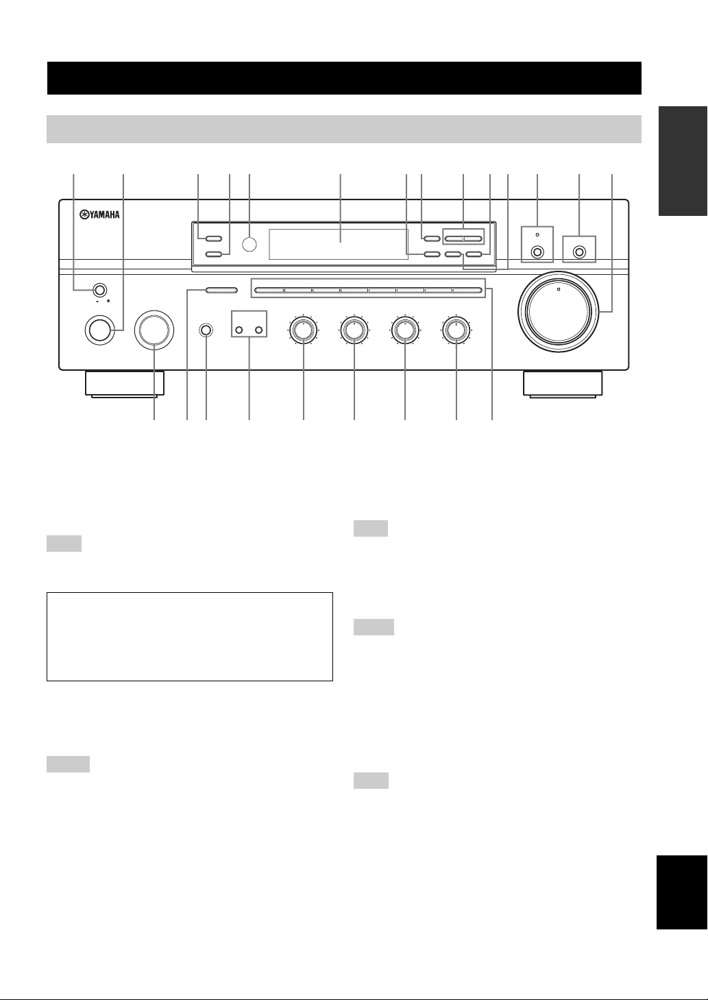
Front panel
12
20
60
26
40
16
-dB
CONTROLS AND FUNCTIONS
CONTROLS AND FUNCTIONS
INTRODUCTION
512 43870A6CB9
ZONE 2 ON/OFF
ZONE CONTROL
MASTER
ON OFF
MAIN ZONE
ON/OFF
INPUT
PHONES
A/B/C/D/E
12345678
BA
BASS
101
22
3
44
55
–
SPEAKERS
GFEHIJKLM
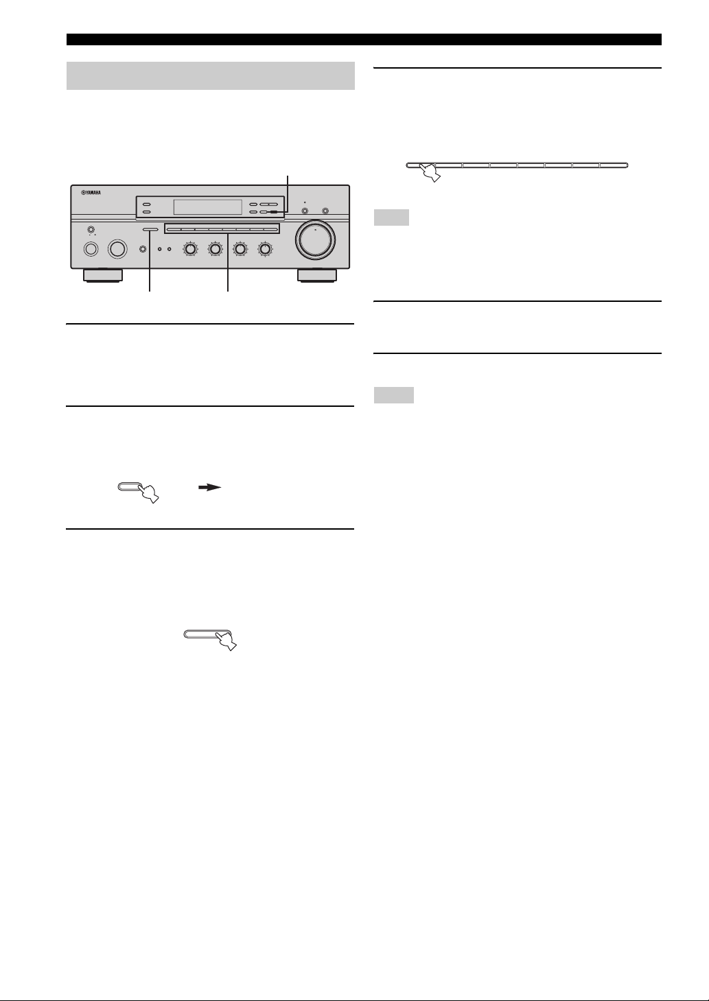
1 MASTER ON/OFF
Press inward to the ON position to turn on the power of
this unit. Press again to release it outward to the OFF
position to turn off this unit.
See page 14 for details.
Note
Even when this unit is turned off, this unit consumes a small
amount of power to preserve the memory.
Memory back-up
The memory back-up circuit prevents the stored data
from being lost. However, the stored data will be lost if
the power cord is disconnected from the AC wall outlet
for more than one week.
2 MAIN ZONE ON/OFF
Turns on Main Zone of this unit or sets it to the standby
mode.
See page 14 for details.
Notes
• This switch is operational only when MASTER ON/OFF is
pressed inward to the ON position.
• In the standby mode, this unit consumes a small amount of
power to receive infrared signals from the remote control.
l
TUNING
h
MEMORY
TUNING MODE
MAN'L/AUTO FM
AUTO/MAN'L
DISPLAY
LOUDNESS
FLAT
1
–
30dB
210
3 9
48
57
6
VOLUME
20
26
40
60
∞
22
3
3
44
+
–
TREBLE
101
55
+
BALANCE
101
22
3
3
44
55
L
FM/AM
EDIT
3
R
(Europe model)
3 ZONE 2 ON/OFF
Turns on Zone 2 or set it to the standby mode. When Zone
2 is turned on, signals are output at the ZONE 2 OUT
jacks.
Note
This switch is operational only when MASTER ON/OFF is
pressed inward to the ON position.
4 ZONE CONTROL
Press to control the input source of Zone 2.
Notes
• This button is operational only when Zone 2 is turned on.
• When you press this button, the ZONE 2 indicator flashes in the
front panel display for approximately 5 seconds. Select the
input source of Zone 2 while the indicator is flashing.
• You can select the preset station when TUNER is selected as the
input source of Zone 2.
5 Remote control sensor
Receives infrared signals from the remote control.
Note
Switch the remote control ID between ID1 and ID2 when using
multiple YAMAHA receivers or amplifiers (see pages 29, 30).
6 Front panel display
Shows information about the operational status of this
unit.
D
MD/TAPE MONITORPURE DIRECT
16
12
8
4
2
0
-dB
English
3
Page 6

CONTROLS AND FUNCTIONS
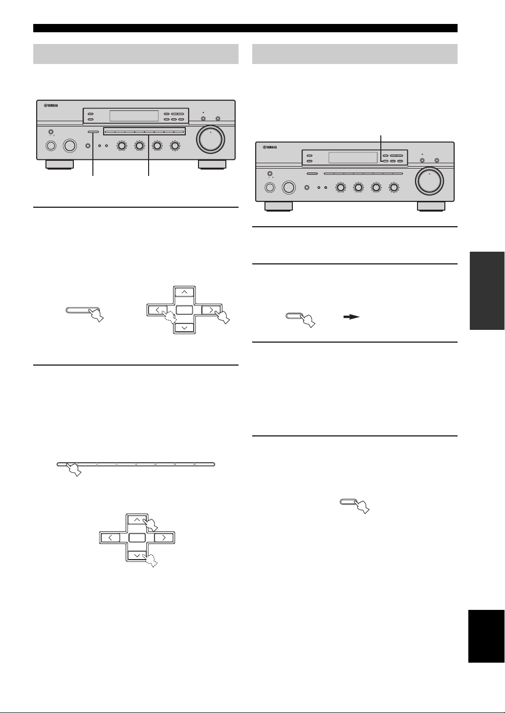
7 EDIT
Exchanges the assignment of two preset stations with each
other when TUNER is selected as the input source (see
page 25).
8 FM/AM
Switches the reception band between AM and FM when
TUNER is selected as the input source (see page 20).
9 TUNING l / h
Selects the tuning frequency when TUNER is selected as
the input source (see page 20).
0 TUNING MODE
Switches the tuning mode between automatic (the AUTO
indicator turns on as a result) and manual (the AUTO
indicator turns off as a result) when TUNER is selected as
the input source.
A MEMORY
Stores a station in the system memory (see page 24).
Sets this unit to the automatic preset tuning mode (see
page 22).
B PURE DIRECT and indicator
Allows you to listen to a source in the purest possible
sound. The indicator above it lights up when this function
is turned on (see page 16).
C MD/TAPE MONITOR
Allows you to listen to the sound played back on the
component connected to the MD/TAPE jacks on the rear
panel of this unit.
When the tape deck is used for recording, you can also
monitor the sound being recorded.
The MD/TAPE MON indicator in the front panel display
lights up when this function is turned on.
Notes
• When this function is on (the indicator lights up), MD/TAPE
cannot be selected with the INPUT selector.
• To listen to the source selected with the INPUT selector, press
again to turn off the function (the indicator turns off as a result).
• When MD/TAPE is selected with the INPUT selector, this
function will not turn on even if MD/TAPE MONITOR is
pressed.
D VOLUME
Increases or decreases the sound output level.
Note
This does not affect the OUT (REC) level.
E INPUT selector
Selects the input source you want to listen to or watch.
F A/B/C/D/E
Selects the preset station group (A to E) when TUNER is
selected as the input source (see page 23).
G PHONES jack
Outputs audio for private listening with your headphones.
Note
Press SPEAKERS A/B so that the SP A/B indicators turn
off before you connect your headphones to the PHONES
jack.
H SPEAKERS A/B
Turns on or off the speaker set connected to the
SPEAKERS A and/or SPEAKERS B terminals on the rear
panel each time the corresponding button is pressed (see
page 15).
I BASS
Increases or decreases the low frequency response. The 0
position produces a flat response (see page 16).
J TREBLE
Increases or decreases the high frequency response. The 0
position produces a flat response (see page 16).
K BALANCE
Adjusts the sound output balance of the left and right
speakers to compensate for sound imbalances caused by
speaker locations or listening room conditions (see page
16).
L LOUDNESS
Retains a full tonal range at any volume level to
compensate for the human ears’ loss of sensitivity to high
and low-frequency ranges at a low volume level (see page
16).
M Preset station number buttons
(1 to 8)
Selects the preset station number (1 to 8) directly when
TUNER is selected as the input source (see page 25).
4
Page 7
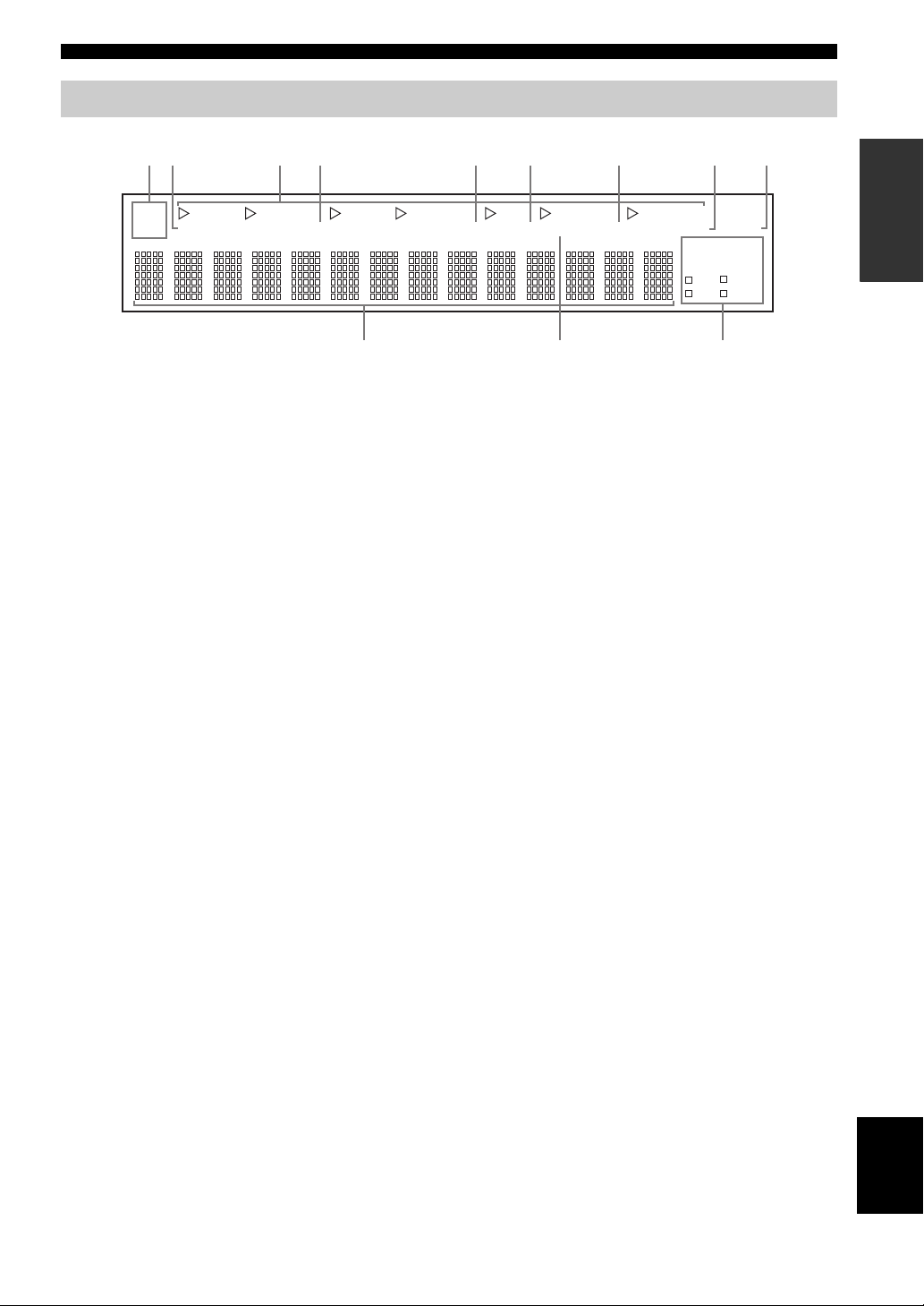
Front panel display
AB0
CONTROLS AND FUNCTIONS
12 5 6 7 839
SP
A B
DVD VCR CD TUNER PHONO
ZONE2 ZONE3
DTV/CBL
4
MD/TAPE
MD/TAPE
MON
1 SP (SPEAKERS) A/B indicators
Light up according to the set of speakers selected.
Both indicators light up when both sets of speakers are
selected.
2 ZONE 2 indicator
Lights up when Zone 2 is turned on.
3 Input source indicators
Light up when this unit is in the corresponding mode.
4 MD/TAPE MON (MONITOR) indicator
Lights up while the MD/TAPE monitor function is turned
on.
5 MEMORY indicator
Flashes for approximately 5 seconds after MEMORY on
the front panel is pressed. While the MEMORY indicator
is flashing, store the displayed station in the system
memory by using A/B/C/D/E and one of the preset station
number buttons on the front panel.
6 AUTO indicator
Lights up when this unit is in the automatic tuning mode.
7 STEREO indicator
Lights up when this unit is receiving a strong signal for an
FM stereo broadcast while the AUTO indicator is lit.
MEMORY AUTO
TUNED STEREO
SLEEP
MUTE
HOLDPTY
EON
PTY
PS
RT
CT
8 SLEEP indicator
Lights up when the sleep timer is turned on.
9 MUTE indicator
Flashes while the MUTE function is turned on.
0 Multi-information display
Shows information when adjusting or changing settings.
A TUNED indicator
Lights up when this unit is tuned into a station.
■ Europe model only
B Radio Data System indicators
The box-shaped indicator beside the name of each Radio
Data System mode lights up when the corresponding
Radio Data System mode is selected.
PTY HOLD indicator
Lights up while searching for stations in the PTY
SEEK mode.
EON indicator
Lights up when the Radio Data System station that
offers the EON data service is being received.
INTRODUCTION
English
5
Page 8
CONTROLS AND FUNCTIONS
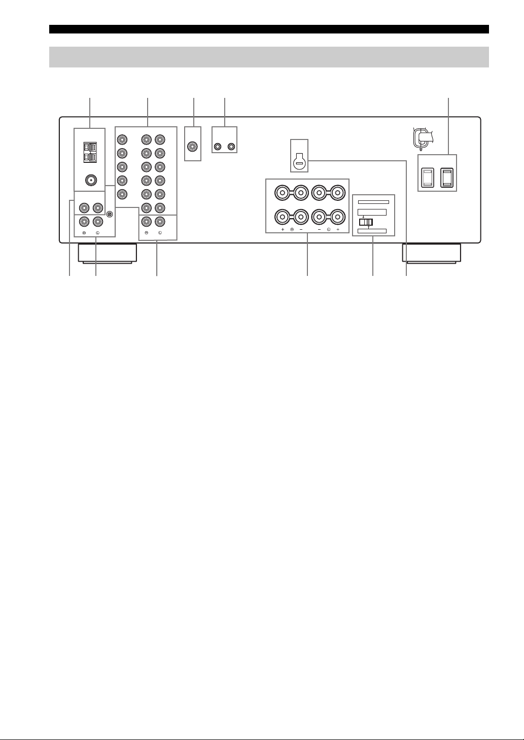
Rear panel
1234
5
(General model)
AUDIOVIDEOTUNER
GND
ANT
75Ω
UNBAL.
ANT
AUDIO GND
CD
PHONO
6 0A79
DVD
DTV/
CBL
AM
IN
VCR
FM
OUT
MONITOR
OUT
OUTPUT
8
1 Antenna terminals
Connect FM and AM antennas.
See page 12 for connections information.
2 AUDIO/VIDEO jacks
Connect audio and video components.
See page 10 for connection information.
3 SUB WOOFER OUTPUT jack
Connect a subwoofer with built-in amplifier.
4 REMOTE jacks
These jacks are used to input/output remote control
signals.
See page 31 for connection information.
5 AC OUTLET(S) (SWITCHED)
Use to supply power to your other audio and video
components.
See page 14 for details.
6 CD jacks
Connect a CD player.
See page 10 for connection information.
(PLAY)
(PLAY)
MD/TAPE
ZONE 2
DVD
DTV/
CBL
IN
VCR
OUT
(REC)
IN
OUT
(REC)
OUTPUT REMOTE
IN OUT
SUB
WOOFER
VOLTAGE
SELECTOR
AC OUTLETS
SWITCHED
SPEAKERS
A
B
IMPEDANCE SELECTOR
SET BEFORE POWER ON
SELECTEUR D'IMPEDANCE
A OR B: 4ΩMIN. /SPEAKER
A + B: 8ΩMIN. /SPEAKER
A OR B: 8ΩMIN. /SPEAKER
7 PHONO jacks and GND terminal
Connect a turntable.
See page 10 for connection information.
8 ZONE 2 jacks
Connect a Zone 2 component.
See page 31 for connection information.
9 SPEAKERS terminals
Connect speakers.
See page 11 for connection information.
0 IMPEDANCE SELECTOR switch
Switches the impedance setting.
See page 11 for details.
■ Asia and General models only
A VOLTAGE SELECTOR
VOLTAGE SELECTOR on the rear panel of this unit must
be set for your local main voltage BEFORE plugging the
power supply cord into the AC wall outlet.
Voltages are as follows:
Asia model......................... AC 220/230–240 V, 50/60 Hz
General model...... AC 110/120/220/230–240 V, 50/60 Hz
6
Page 9
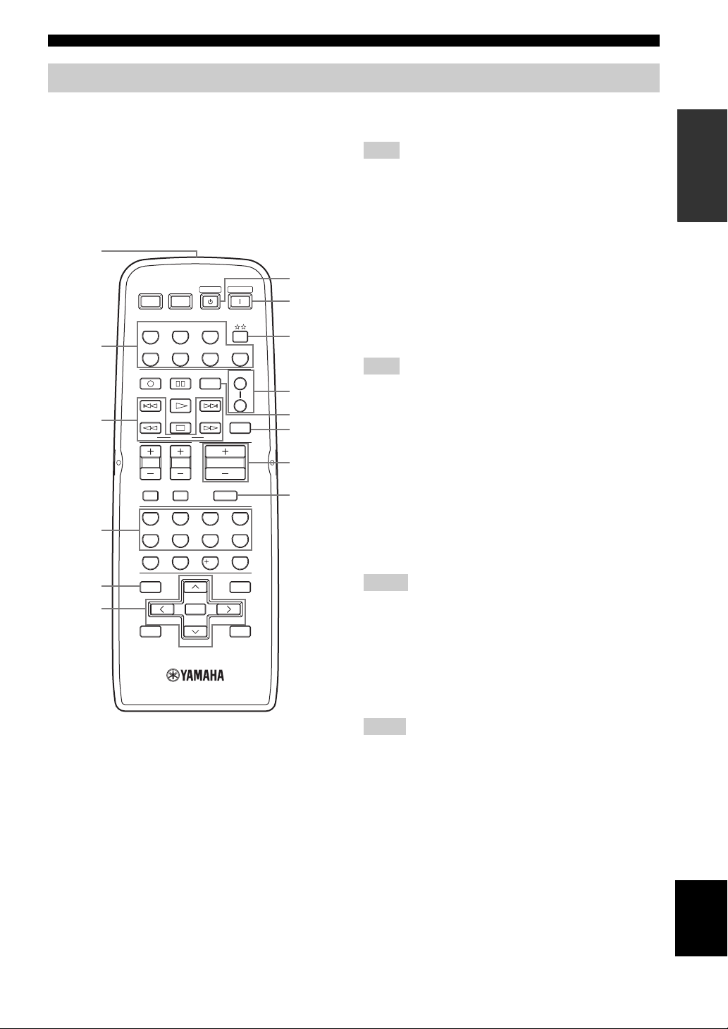
Remote control
CONTROLS AND FUNCTIONS
This section describes the function of each button on the
remote control used to control this unit or other
components made by YAMAHA or other manufacturers.
The functions of the buttons used to control your other
audio and video components are the same as those of the
corresponding buttons on those components. Refer to
those components’ instruction manuals for details. To
operate other components using this remote control, see
“REMOTE CONTROL FEATURES” on page 33.
1
7
8
9
A
0
B
A
B
C
D
2
3
4
5
6
POWER POWER
CD
REC
DISC SKIP
FREQ/TEXT
MODE PTY SEEK
TV VOL
TV MUTE TV INPUT
BAND
A/B/C/D/E A/B/C/D/E
AVTV
MD/TAPE
DTV/CBL
TV CH
65
09
STANDBY
TUNER
VCR
CODE SET
START
ENTER
PRESET/CH
(Europe model)
EON
VOLUME
MUTE
7
10
POWER
PHONODVD
SPEAKERS
SLEEP
4321
8
ENT.
MENUTITLE
DISPLAYRETURN
1 Infrared signal transmitter
Sends infrared signals.
2 Input selector buttons
Select the desired input source and change the control area
(see page 33).
3 Radio Data System control buttons
Controls the Radio Data System features.
Note
The Radio Data System features (FREQ/TEXT, EON, PTY
SEEK MODE and PTY SEEK START) are only applicable to the
Europe model and are operational only when TUNER is selected
as the input source. For details, see “Receiving Radio Data
System stations” on page 26.
4 Numeric buttons (1 to 8)
Select the preset station number (1 to 8) when TUNER is
selected as the input source.
5 BAND
Switches to the previously used reception band (FM or
AM) when TUNER is selected as the input source.
Note
The frequency of the previously received station is automatically
recalled.
6 A/B/C/D/E j / i
Selects the preset station group (A to E) when TUNER
is selected as the input source (see page 25).
PRESET/CH u / d
Selects the preset station number (1 to 8) when
TUNER is selected as the input source (see page 25).
7 STANDBY
Sets this unit to the standby mode.
Notes
• This button is operational only when MASTER ON/OFF on the
front panel is pressed inward to the ON position.
• In the standby mode, this unit consumes a small amount of
power to receive infrared signals from the remote control.
• This button does not set Zone 2 to the standby mode.
8 POWER
Turns on this unit.
Notes
• This button is operational only when MASTER ON/OFF on the
front panel is pressed inward to the ON position.
• This button does not turn on Zone 2.
INTRODUCTION
7
English
Page 10

CONTROLS AND FUNCTIONS
9
Changes the control area (see page 33).
0 SPEAKERS A/B
Turns on or off the set of speakers connected to the
SPEAKERS A and/or SPEAKERS B terminals on the rear
panel of this unit when the corresponding button is
pressed each time.
A CODE SET
Use to set up remote control codes (see page 35).
B SLEEP
Sets the sleep timer.
C VOLUME +/–
Increases or decreases the sound output level.
Notes
• This does not affect the OUT (REC) level.
• When you press VOLUME +/– to control the sound output
level of this unit, VOLUME on the front panel rotates.
D MUTE
Mutes the sound output. Press again to restore the sound
output to the previous volume level (see page 19).
Note
The sound output to Zone 2 is not muted.
8
Page 11
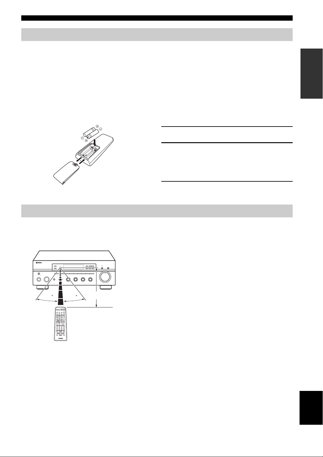
Installing batteries in the remote control
CONTROLS AND FUNCTIONS
■ Notes on batteries
• Change all of the batteries if the operation range of the remote control decreases.
• Use AA, R6, UM-3 batteries for the remote control.
• Make sure that the polarities are correct. See the illustration inside the battery compartment of each remote control.
• Remove the batteries if the remote control is not used for an extended period of time.
• Do not use old batteries together with new ones.
• Do not use different types of batteries (such as alkaline and manganese batteries) together. Read the packaging carefully as these
different types of batteries may have the same shape and color.
• We strongly recommend using alkaline batteries.
• If the batteries have leaked, dispose of them immediately. Avoid touching the leaked material or letting it come into contact with
clothing, etc. Clean the battery compartment thoroughly before installing new batteries.
• Do not throw away batteries with general house waste; dispose of them correctly in accordance with your local regulations.
1 Open the battery compartment cover.
2
2 Insert the supplied batteries in each remote
1
3
control according to the polarity markings (+
and –) on the inside of the battery
compartment.
3 Close the cover back.
Using the remote control
The remote control transmit a directional infrared beam.
Be sure to aim the remote control directly at the remote control sensor on the front panel of this unit or on the infrared
signal receiver in Zone 2 during operation.
■ Handling the remote control
• The area between the remote control and this unit (or the
l
TUNING
ZONE 2 ON/OFF
ZONE CONTROL
MASTER
A/B/C/D/E
INPUT
12345678
PHONES
SPEAKERS
BA
3
BASS
101
22
44
55
+
–
3
22
3
44
–
ON OFF
MAIN ZONE
ON/OFF
30 30
POWER POWER
STANDBY
POWER
AVTV
CD
MD/TAPE
TUNER
PHONODVD
VCR
DTV/CBL
REC
CODE SET
SPEAKERS
A
DISC SKIP
B
EON
FREQ/TEXT
SLEEP
START
MODE PTY SEEK
VOLUME
TV VOL
TV CH
TV MUTE TV INPUT
MUTE
4321
81070965
ENT.
MENUTITLE
BAND
ENTER
A/B/C/D/E A/B/C/D/E
DISPLAYRETURN
PRESET/CH
h
TREBLE
101
55
3
+
BALANCE
101
22
3
44
55
L
FM/AM
EDIT
3
R
MEMORY
MAN'L/AUTO FM
LOUDNESS
FLAT
1
210
3
48
57
6
MD/TAPE MONITORPURE DIRECT
TUNING MODE
AUTO/MAN'L
VOLUME
–
30dB
9
Approximately 6 m (19.7 ft)
infrared signal receiver in Zone 2) must be clear of large
obstacles.
• Do not spill water or other liquids on the remote control.
• Do not drop the remote control.
• Do not leave or store the remote control in the following types
of conditions:
– places of high humidity, such as near a bath
– places of high temperature, such as near a heater or a stove
– places of extremely low temperatures
– dusty places
• Do not expose the remote control sensor to strong lighting, in
particular, an inverter type fluorescent lamp; otherwise, the
remote control may not work properly. If necessary, position
this unit away from direct lighting.
INTRODUCTION
9
English
Page 12
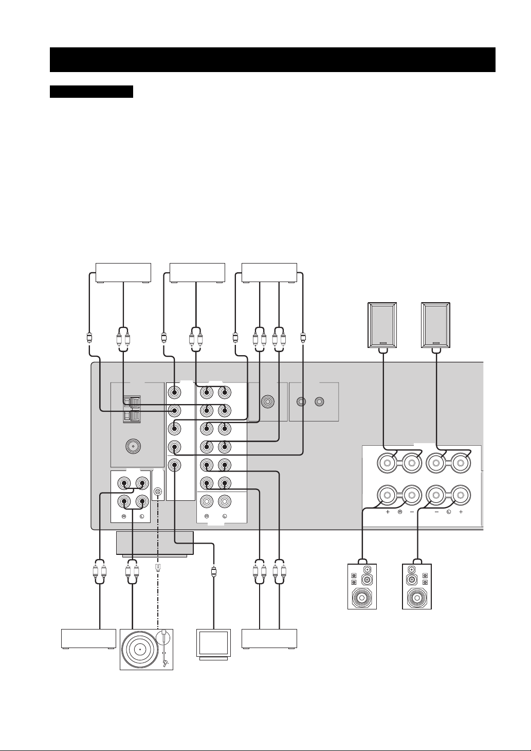
CONNECTIONS
CONNECTIONS
CAUTION
• Do not connect this unit or other components to the main power until all connections between components are complete.
• Do not let the bare speaker wires touch each other or do not let them touch any metal part of this unit. This could damage this unit and/
or the speakers.
• All connections must be correct: L (left) to L, R (right) to R, “+” to “+” and “–” to “–”. If the connections are faulty, no sound will be
heard from the speakers, and if the polarity of the speaker connections is incorrect, the sound will be unnatural and lack bass. Also,
refer to the owner’s manual for each of your components.
• Use the RCA type pin plug cables for audio and video components except speakers.
y
• The PHONO jacks are designed to connect a turntable with an MM or high-output MC cartridge. If you have a turntable with a lowoutput MC cartridge, use an in-line boosting transformer or an MC-head amplifier when connecting your turntable to the PHONO
jacks.
• Connect your turntable to the GND terminal to reduce noise in the signal. However, you may hear less noise without the connection to
the GND terminal for some record players.
Digital TV,
Cable TV
DVD player
VCR, etc.
Video out
Audio out
Video out
Audio out
Video out
Audio in
Audio out
Video in
Speakers A
V
75Ω
UNBAL.
AUDIO GND
CD
PHONO
R L
R L
Audio out
V
GND
GND
AM
ANT
FM
ANT
GND
Audio out
MONITOR
OUT
LRLR
DVD
DTV/
CBL
IN
VCR
OUT
V V
AUDIOVIDEOTUNER
DVD
DTV/
CBL
IN
(PLAY)
VCR
OUT
(REC)
IN
(PLAY)
MD/TAPE
OUT
(REC)
ZONE 2
OUTPUT
V
Video in
LR LR
OUTPUT REMOTE
SUB
WOOFER
R
R
L
L
Audio out
Audio in
IN OUT
––+
+
SPEAKERS
A
B
+ – – +
10
CD player
Turntable
Video
monitor
Speakers B
MD recorder,
Tape deck, etc.
Page 13
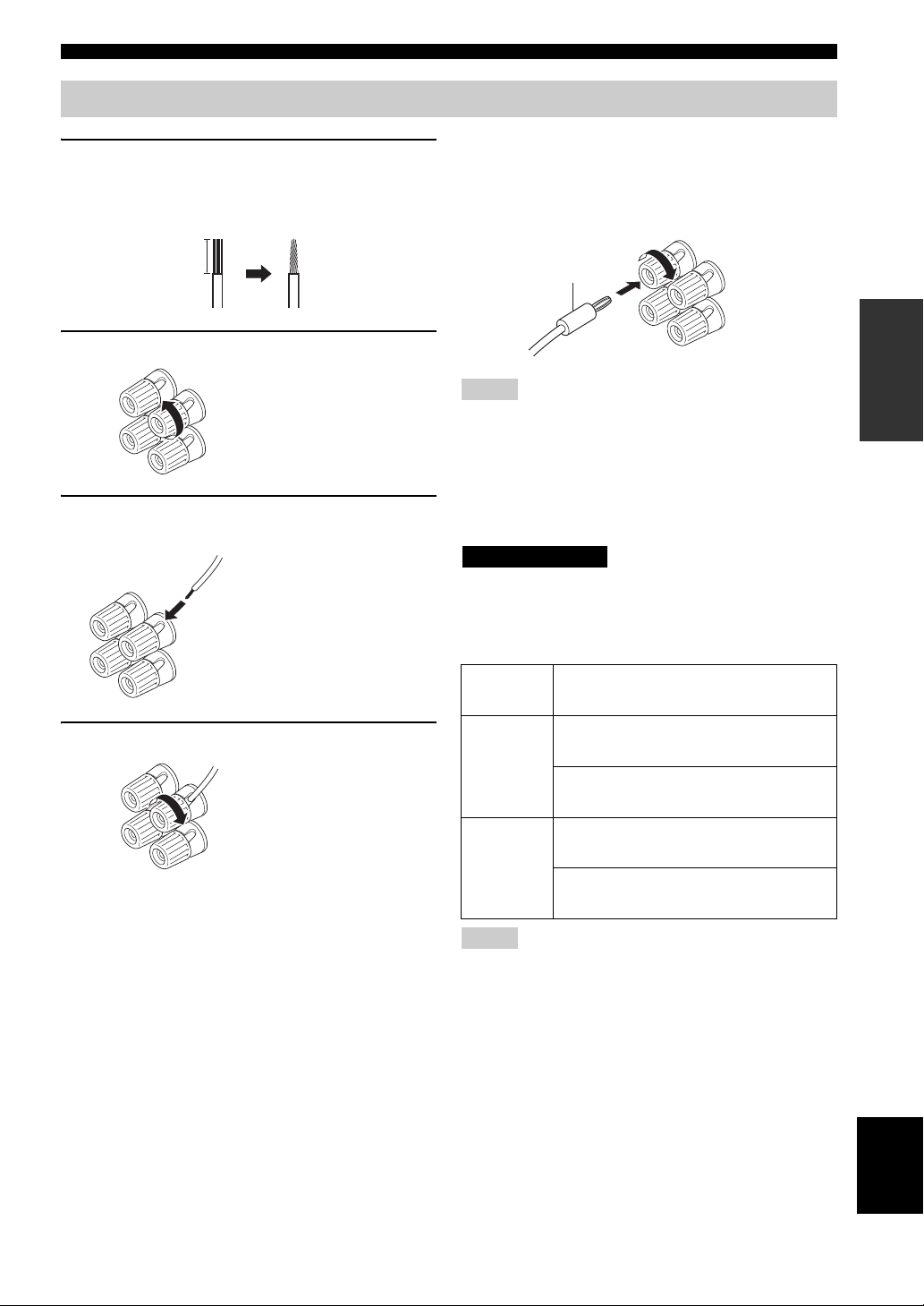
Connecting speakers
1 Remove approximately 10 mm (3/8 in) of
insulation from the end of each speaker
cable and twist the exposed wires of the
cable together to prevent short circuits.
10 mm (3/8 in)
2 Unscrew the knob.
CONNECTIONS
■ Connecting the banana plug
(U.S.A., Canada, Australia and General
models only)
First, tighten the knob and then insert the banana plug into
the end of the corresponding terminal.
Banana plug
PREPARATION
Red: positive (+)
Black: negative (–)
3 Insert one bare wire into the hole in the side
of each terminal.
Red: positive (+)
Black: negative (–)
4 Tighten the knob to secure the wire.
Red: positive (+)
Black: negative (–)
Notes
• One or two speaker sets can be connected to this unit. If you use
only one speaker set, connect it to either the SPEAKERS A or B
terminals.
• Use speakers with the specified impedance shown on the rear
panel of this unit.
■ IMPEDANCE SELECTOR
CAUTION
Do not slide the IMPEDANCE SELECTOR switch while the
power of this unit is turned on, as doing so may damage the unit.
Select the switch position (left or right) according to the
impedance of the speakers in your system.
Switch
position
If you use one set (A or B), the impedance of
each speaker must be 8
Right
If you use two sets (A and B), the impedance
of each speaker must be 16
If you use one set (A or B), the impedance of
each speaker must be 4
Left
If you use two sets (A and B), the impedance
of each speaker must be 8
Impedance level
Ω or higher.
Ω or higher.
Ω or higher.
Ω or higher.
Notes
• The Canada model cannot use two speaker sets (A and B)
simultaneously when the IMPEDANCE SELECTOR switch is
slid to the right position.
• If this unit fails to turn on, the IMPEDANCE SELECTOR
switch may not be fully slid to either position. If this is the case,
slide the switch all the way to either position when the power
supply to this unit is completely cut off.
English
11
Page 14
CONNECTIONS
V
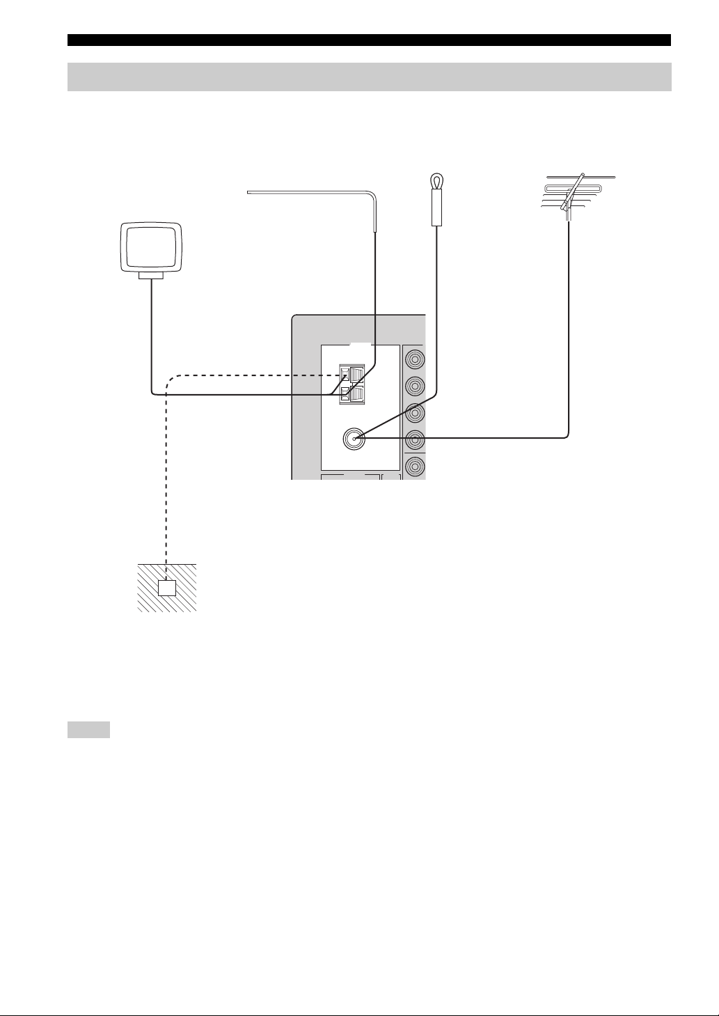
Connecting the AM and FM antennas
Both AM and FM indoor antennas are included with this unit. In general, these antennas should provide sufficient signal
strength. Connect each antenna correctly to the designated terminals.
AM
Indoor FM
antenna
(included)
or
Outdoor FM
antenna
AM loop antenna
(included)
Outdoor AM antenna
Use a 5 to 10 m of vinylcovered wire extended
outdoors from a window.
TUNER
GND
ANT
75Ω
UNBAL.
FM
ANT
AUDIO GND
Ground (GND terminal)
For maximum safety and
minimum interference, connect
the antenna GND terminal to a
good earth ground. A good earth
ground is a metal stake driven into
moist earth.
Notes
• A properly installed outdoor antenna provides clearer reception than an indoor one. If you experience poor reception quality, an
outdoor antenna may improve the quality. Consult your nearest authorized YAMAHA dealer or service center about outdoor antennas.
• If you connect an outdoor FM antenna to this unit, do not connect the indoor FM antenna to this unit.
• To minimize interference from automobile ignition, locate the antenna as far from heavy traffic as possible.
• Keep the feeder cable or coaxial cable as short as possible. Do not bundle or roll up excess cable.
• The antenna should be placed at least 2 meters from reinforced concrete walls or metal structures.
12
Page 15
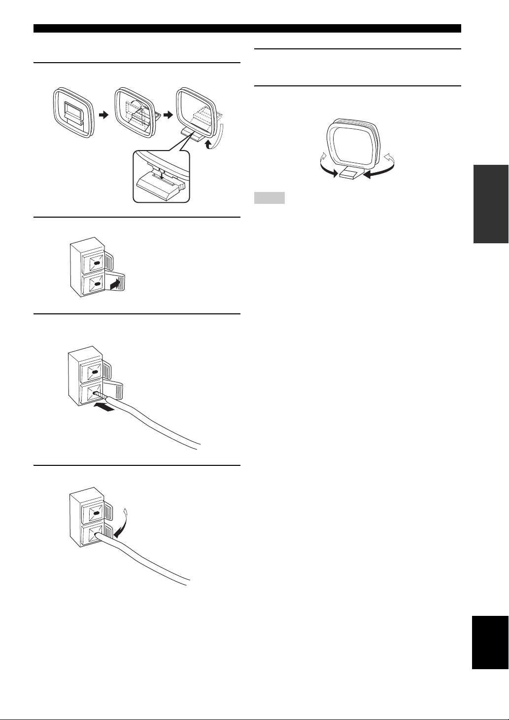
■ Connecting the AM loop antenna
1 Set up the AM loop antenna.
2 Press and hold the tab.
CONNECTIONS
5 Repeat steps 2 to 4 to insert the AM loop
antenna lead wires into the GND terminal.
6 Orient the AM loop antenna for the best
reception.
PREPARATION
Notes
• The AM loop antenna should be placed away from this unit.
• A properly installed outdoor antenna provides clearer reception
than an indoor one. If you experience poor reception quality, an
outdoor antenna may improve the quality. It is recommended
that you should connect a 5 to 10 m of vinyl-covered wire to the
AM ANT terminal and extend it outdoors from a window.
Consult your nearest authorized YAMAHA dealer or service
center about outdoor antennas.
• The AM loop antenna should always be connected, even if an
outdoor AM antenna is connected to this unit.
3 Insert the AM loop antenna lead wires into
the AM ANT terminal.
4 Release the tab.
13
English
Page 16
CONNECTIONS
12
20
60
26
40
16
-dB
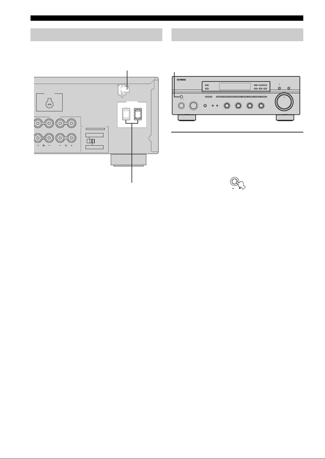
Connecting the power supply cord
Plug the power supply cord into the AC wall outlet after
all other connections are complete.
AC power supply cord
VOLTAGE
SELECTOR
AC OUTLETS
SWITCHED
SPEAKERS
IMPEDANCE SELECTOR
SET BEFORE POWER ON
A OR B: 4ΩMIN. /SPEAKER
A + B: 8ΩMIN. /SPEAKER
A OR B: 8ΩMIN. /SPEAKER
A + B:16ΩMIN. /SPEAKER
(General model)
AC OUTLET(S)
■ AC OUTLET(S) (SWITCHED)
Australia model ..................................................... 1 outlet
Other models ....................................................... 2 outlets
Use these outlets to connect the power supply cords from
your other components to this unit. The outlets supply
power to any connected components whenever the power
of this unit is turned on. For information on the maximum
power (total power consumption of components), see
“SPECIFICATIONS” on page 39.
Turning on and off this unit
When all connections are complete, turn on the power of
this unit.
1
l
TUNING
BALANCE
101
22
3
3
44
55
R
L
FM/AM
EDIT
MEMORY
MAN'L/AUTO FM
LOUDNESS
FLAT
1
210
3
48
57
h
TUNING MODE
AUTO/MAN'L
–
30dB
9
6
MD/TAPE MONITORPURE DIRECT
16
20
12
VOLUME
26
8
40
4
2
60
0
∞
-dB
ZONE 2 ON/OFF
ZONE CONTROL
MASTER
ON OFF
MAIN ZONE
ON/OFF
A/B/C/D/E
INPUT
12345678
BASS
SPEAKERS
BA
101
22
3
44
55
–
PHONES
3
+
TREBLE
101
22
3
3
44
55
+
–
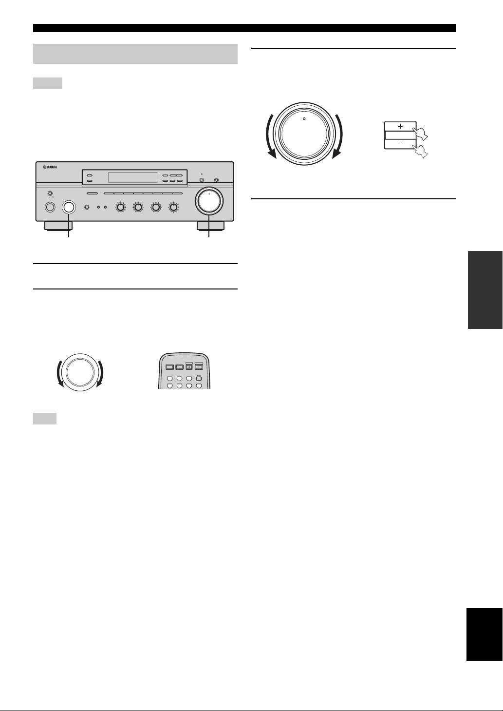
1 Press MASTER ON/OFF on the front panel
inward to the ON position to turn on the
power of this unit.
Main Zone of this unit turns on.
MASTER
ON OFF
• You can set Main Zone of this unit to the standby mode
by pressing MAIN ZONE ON/OFF on the front panel
or STANDBY on the remote control.
Press MAIN ZONE ON/OFF on the front panel or
POWER on the remote control to turn Main Zone on
again.
• Press MASTER ON/OFF on the front panel again to
release it outward to the OFF position to turn off this
unit.
y
While MASTER ON/OFF on the front panel is pressed inward to
the ON position, you can turn on Zone 2 or set it to the standby
mode independently (see page 32).
14
Page 17
PLAYING AND RECORDING
12
20
60
26
40
16
-dB
12
20
60
26
40
16
-dB
l
PLAYING AND RECORDING
CAUTION
Extreme caution should be exercised when you play back CDs encoded in DTS.
If you play back a CD encoded in DTS on a DTS-incompatible CD player, you will only hear some unwanted noise that may damage
your speakers. Check whether your CD player supports CDs encoded in DTS. Also, check the sound output level of your CD player
before you play back a CD encoded in DTS.
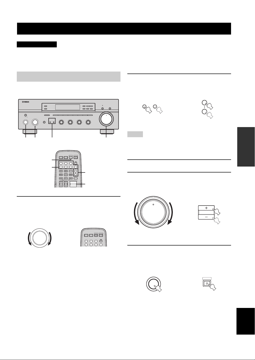
Playing a source
l
TUNING
BALANCE
101
22
3
3
44
55
R
L
A
B
FM/AM
EDIT
MEMORY
MAN'L/AUTO FM
LOUDNESS
1
210
3
48
57
2
4
POWER POWER
CD
h
TUNING MODE
AUTO/MAN'L
FLAT
–
30dB
9
6
MD/TAPE MONITORPURE DIRECT
16
20
12
VOLUME
26
8
40
4
2
60
0
∞
-dB
4
STANDBY
POWER
AVTV
MD/TAPE
TUNER
PHONODVD
DTV/CBL
VCR
ZONE 2 ON/OFF
ZONE CONTROL
MASTER
ON OFF
MAIN ZONE
ON/OFF
5
A/B/C/D/E
INPUT
SPEAKERS
PHONES
1 2
5
1
12345678
BASS
TREBLE
101
101
22
22
BA
3
44
55
+
–
POWER POWER
AVTV
CD
MD/TAPE
DTV/CBL
REC
DISC SKIP
FREQ/TEXT
MODE PTY SEEK
TV VOL
TV CH
3
3
44
55
+
–
STANDBY
TUNER
VCR
CODE SET
EON
START
VOLUME
POWER
PHONODVD
SPEAKERS
SLEEP
3
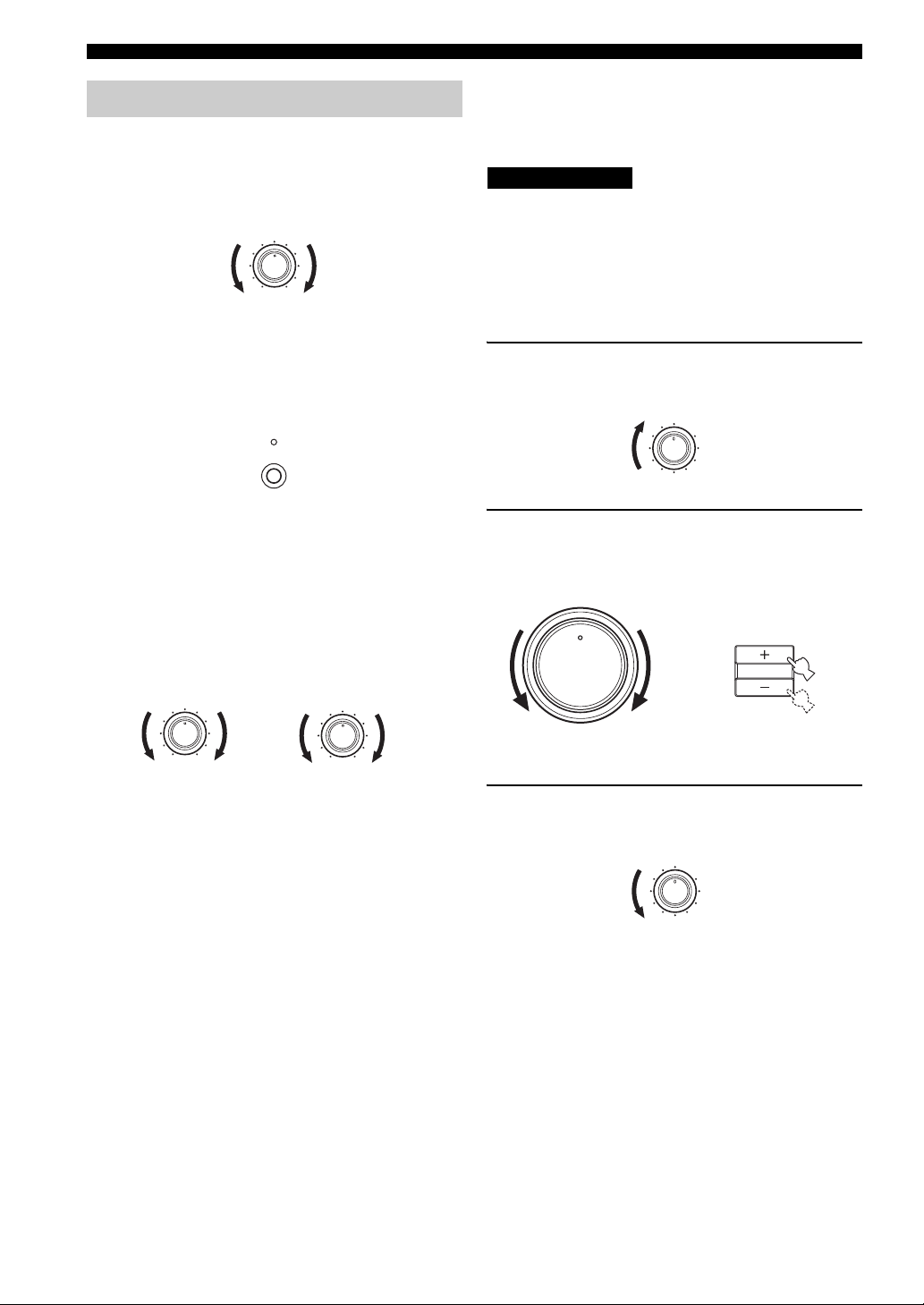
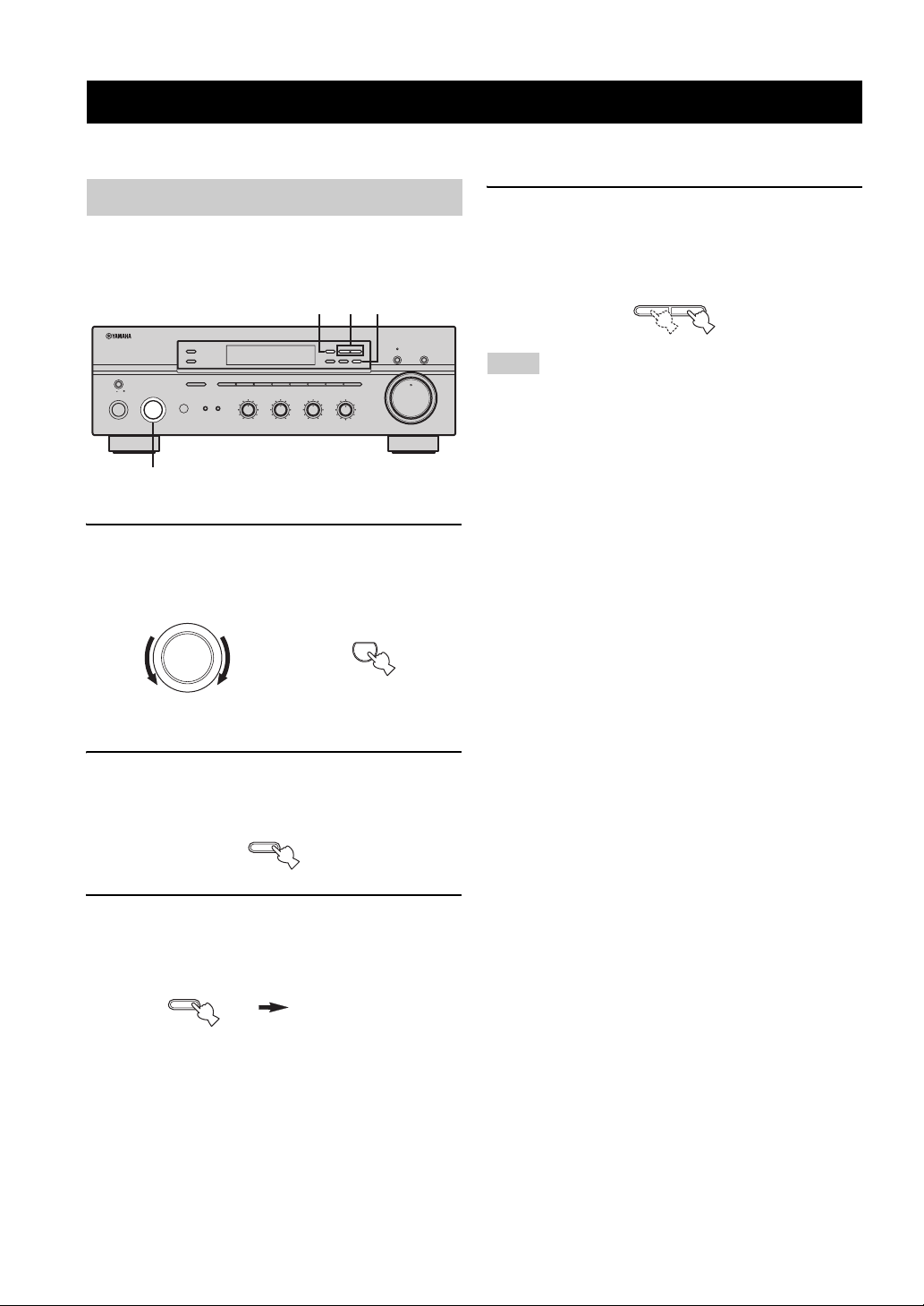
1 Rotate the INPUT selector on the front panel
(or press one of the input selector buttons on
the remote control) to select the desired
input source.
INPUT
or
Front panel Remote control
2 Press SPEAKERS A and/or SPEAKERS B on
the front panel or on the remote control to
select speakers A and/or speakers B.
SPEAKERS
BA
Front panel
or
SPEAKERS
A
B
Remote control
Notes
• Both SPEAKERS A and B can be selected.
• Make sure that the IMPEDANCE SELECTOR switch is
correctly set (see page 11).
3 Play the source.
4 Rotate VOLUME on the front panel (or press
VOLUME +/– on the remote control) to adjust
the sound output level.
16
20
VOLUME
26
40
60
Front panel
12
8
4
2
∞
0
-dB
or
VOLUME
Remote control
5 Press MAIN ZONE ON/OFF on the front panel
again (or press STANDBY on the remote
control) to finish using this unit and set it to
the standby mode.
MAIN ZONE
ON/OFF
or
STANDBY
OPERATION
BASIC
Front panel
Remote control
English
15
Page 18
PLAYING AND RECORDING
12
20
60
26
40
16
-dB
Adjusting the tonal quality
■ Adjusting the BALANCE control
Adjusts the sound output balance of the left and right
speakers to compensate for sound imbalance caused by
speaker locations or listening room conditions.
BALANCE
101
22
3
■ Using the PURE DIRECT button
Routes input signals from your audio sources so that the
input signals bypass the BASS, TREBLE, BALANCE and
LOUDNESS controls, thus eliminating any alterations to
the audio signals and creating the purest possible sound.
3
44
55
R
L
PURE DIRECT
■ Adjusting the LOUDNESS control
Retains a full tonal range at any volume level, thus
compensating for the human ears’ loss of sensitivity to
high and low-frequency ranges at a low volume level.
CAUTION
If the PURE DIRECT button is turned on with the LOUDNESS
control set at a certain level, the input signals bypass the
LOUDNESS control, resulting in a sudden increase in the sound
output level. To prevent your ears or the speakers from being
undesirably damaged, be sure to press the PURE DIRECT button
after lowering the sound output level or after checking that the
LOUDNESS control is properly set.
1 Rotate the LOUDNESS control on the front
panel to the FLAT position.
LOUDNESS
FLAT
1
–
30dB
210
3
9
48
57
6
■ Adjusting the BASS and TREBLE
controls
Adjust the high and low frequency response.
BASS
Increases or decreases the low frequency response.
TREBLE
Increases or decreases the high frequency response.
BASS
101
22
3
3
44
55
+
–
TREBLE
101
22
3
3
44
55
+
–
2 Rotate VOLUME on the front panel (or press
VOLUME +/– on the remote control) to set the
sound output level to the loudest listening
level that you would listen to.
16
20
VOLUME
26
40
60
Front panel
12
8
4
or
2
0
∞
-dB
VOLU ME
Remote control
3 Rotate the LOUDNESS control until the
desired volume is obtained.
LOUDNESS
FLAT
1
–
30dB
210
3
9
48
57
6
16
Page 19
PLAYING AND RECORDING
12
20
60
26
40
16
-dB
12
20
60
26
40
16
-dB
Recording a source
Notes
• The VOLUME, BASS, TREBLE, BALANCE and
LOUDNESS controls and the PURE DIRECT buttons have no
effect on the source being recorded.
• Check the copyright laws in your country to record from
records, CDs, radio, etc. Recording copyright-protected
material may infringe on copyright laws.
l
TUNING
ZONE 2 ON/OFF
ZONE CONTROL
MASTER
ON OFF
MAIN ZONE
ON/OFF
A/B/C/D/E
INPUT
12345678
BASS
SPEAKERS
BA
101
22
3
44
55
–
PHONES
3
+
TREBLE
101
22
3
3
44
55
+
–
2
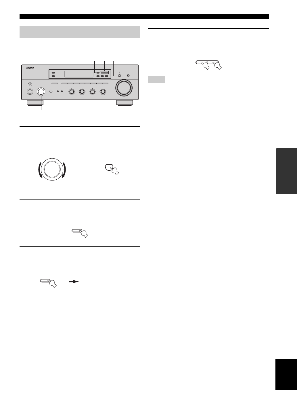
1 Play the selected source to record from.
2 Rotate the INPUT selector on the front panel
(or press one of the input selector buttons on
the remote control) to select the source you
want to record from.
INPUT
or
FM/AM
BALANCE
101
22
3
3
44
55
R
L
EDIT
MEMORY
MAN'L/AUTO FM
LOUDNESS
FLAT
1
210
3
48
57
6
POWER POWER
CD
MD/TAPE
DTV/CBL
h
TUNING MODE
AUTO/MAN'L
–
30dB
9
MD/TAPE MONPURE DIRECT
16
20
12
VOLUME
26
8
40
4
2
60
0
∞
-dB
3
STANDBY
POWER
AVTV
TUNER
PHONODVD
VCR
3 Rotate VOLUME on the front panel (or press
VOLUME +/– on the remote control) to adjust
the sound output level of the selected source
to record from.
16
20
VOLUME
26
40
60
Front panel
12
8
or
4
2
0
∞
-dB
VOLUME
Remote control
4 Begin recording on the MD recorder, the tape
deck or the VCR connected to this unit.
y
If the 3-head tape deck is used for recording, you can monitor the
sound of recording by pressing MD/TAPE MONITOR on the
front panel.
OPERATION
BASIC
Front panel Remote control
Note
You cannot select any input source while the MD/TAPE MON
indicator in the front panel display lights on.
English
17
Page 20
PLAYING AND RECORDING
Using the sleep timer
Use this feature to automatically set this unit to the
standby mode after a certain amount of time. The sleep
timer is useful when you are going to sleep while this unit
is playing or recording a source. The sleep timer also
automatically turns off any external components
connected to the AC OUTLET(S).
POWER POWER
STANDBY
POWER
AVTV
CD
MD/TAPE
TUNER
PHONODVD
DTV/CBL
REC
DISC SKIP
FREQ/TEXT
MODE PTY SEEK
TV VOL
POWER POWER
CD
MD/TAPE
DTV/CBL
VCR
CODE SET
SPEAKERS
A
B
EON
SLEEP
START
VOLUME
TV CH
STANDBY
AVTV
TUNER
VCR
3
POWER
PHONODVD
1
Notes
• The sleep timer can only be set with the remote control.
• The sleep timer automatically turns off Zone 2. However, the
power of Zone 2 components are not turned off.
1 Press one of the input selector buttons on
the remote control to select an input source.
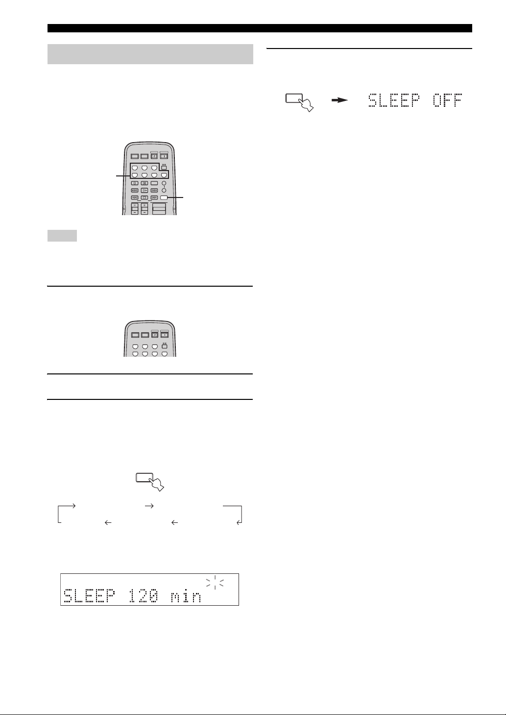
4 Press SLEEP repeatedly so that SLEEP OFF
appears in the front panel display.
SLEEP
After a few seconds, SLEEP OFF disappears from the
front panel display, and the SLEEP indicator turns
off.
y
The sleep timer setting can also be canceled by pressing
STANDBY on the remote control (or MAIN ZONE ON/OFF or
MASTER ON/OFF on the front panel) to set this unit to the
standby mode.
2 Start playback on the selected input source.
3 Press SLEEP repeatedly to set the amount of
time before this unit is set to the standby
mode.
Each time you press SLEEP, the front panel display
changes as shown below.
SLEEP
SLEEP 120 min SLEEP 90 min
SLEEP 60 minSLEEP 30 minSLEEP OFF
The SLEEP indicator flashes while switching the
amount of time for the sleep timer.
SLEEP
18
Page 21
Muting the sound output
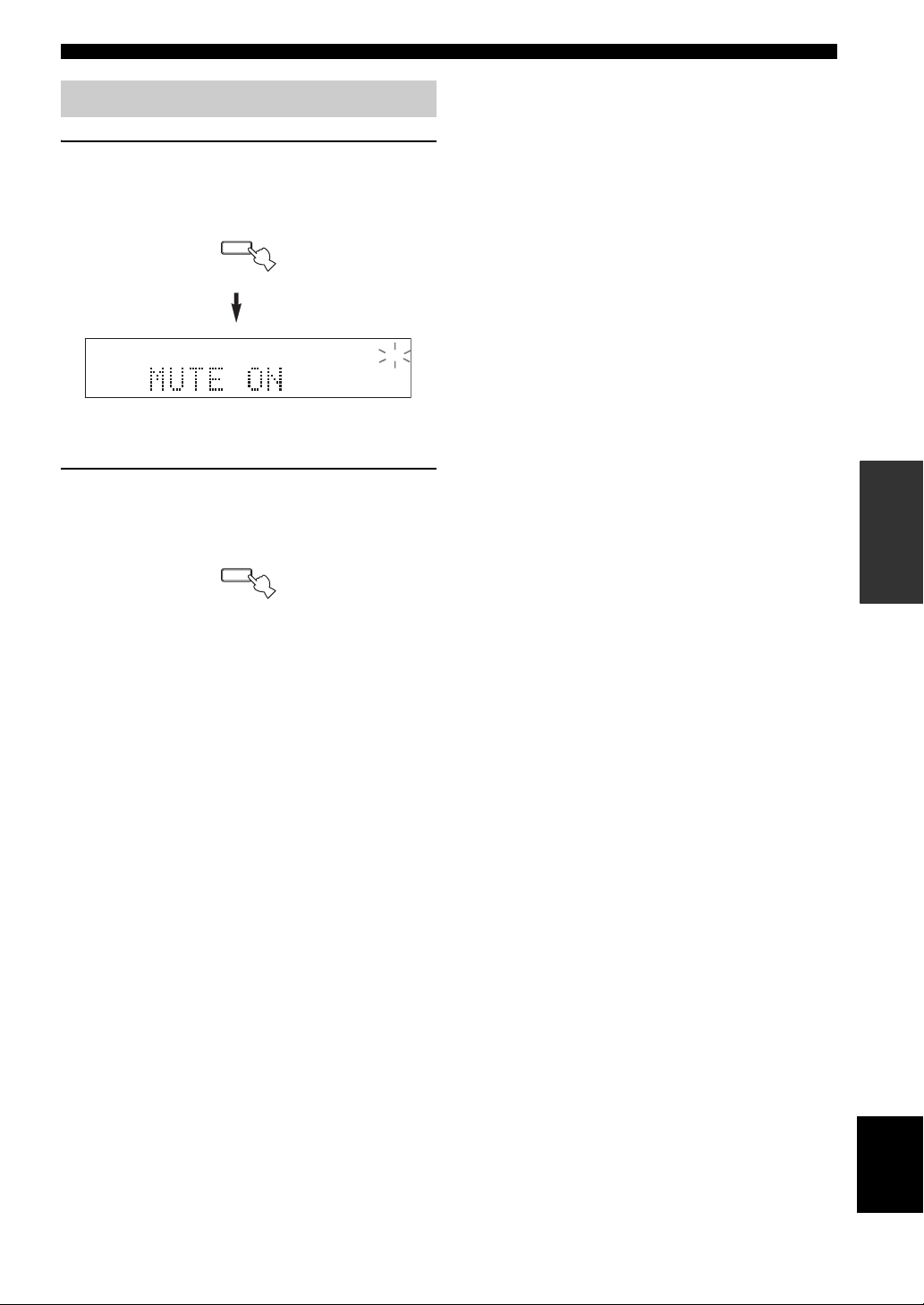
1 Press MUTE on the remote control to mute
the sound output.
The MUTE indicator flashes in the front panel
display.
MUTE
MUTE
After a few seconds, MUTE ON disappears from the
front panel display.
PLAYING AND RECORDING
2 Press MUTE on the remote control again to
resume the sound output.
The MUTE indicator disappears from the front panel
display.
MUTE
OPERATION
BASIC
19
English
Page 22
FM/AM TUNING
12
20
60
26
40
16
-dB
FM/AM TUNING
There are 2 tuning methods; automatic and manual. Select either method according to your preference and the strength of
station signals.
Automatic tuning
Automatic tuning is effective when station signals are
strong and there is no interference.
2 4 3
l
TUNING
ZONE 2 ON/OFF
ZONE CONTROL
MASTER
ON OFF
MAIN ZONE
ON/OFF
A/B/C/D/E
INPUT
12345678
TREBLE
BASS
SPEAKERS
101
22
3
3
44
55
+
–
101
22
3
3
44
55
+
–
BA
1
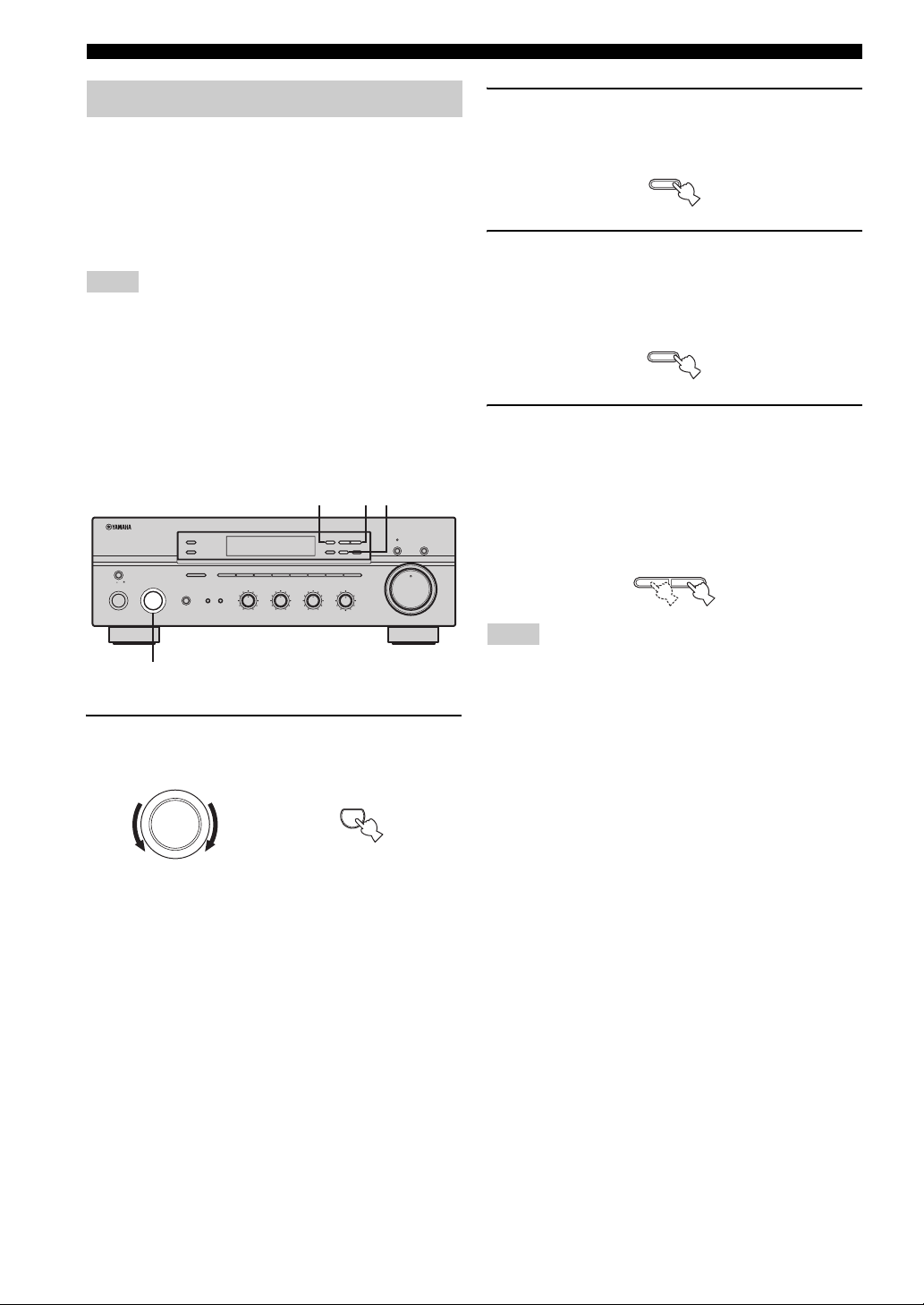
1 Rotate the INPUT selector (or press TUNER
on the remote control) to select TUNER as
the input source.
INPUT
or
Front panel Remote control
FM/AM
BALANCE
101
22
3
3
44
55
R
L
EDIT
MEMORY
MAN'L/AUTO FM
LOUDNESS
FLAT
1
210
3
48
57
6
h
TUNING MODE
AUTO/MAN'L
–
30dB
9
TUNER
MD/TAPE MONITORPURE DIRECT
16
20
12
VOLUME
26
8
40
4
2
60
0
∞
-dB
4 Press TUNING l / h once to begin
automatic tuning.
Press h to tune into a higher frequency.
Press l to tune into a lower frequency.
l
TUNING
h
Notes
• When you tune into a station, the frequency of the received
station is shown in the front panel display.
• To search for another station, press TUNING l / h once more.
• If the tuning search does not stop at the desired station because
the station signals are weak, try using the manual tuning
method.
2 Press FM/AM on the front panel to select the
reception band (FM or AM).
FM or AM appears in the front panel display.
FM/AM
3 Press TUNING MODE on the front panel so
that the AUTO indicator lights up in the front
panel display.
TUNING MODE
AUTO/MAN'L
AUTO
Lights up
20
Page 23
FM/AM TUNING
12
20
60
26
40
16
-dB
Manual tuning
Manual tuning is effective when station signals are weak.
2 4 3
l
TUNING
ZONE 2 ON/OFF
ZONE CONTROL
MASTER
ON OFF
MAIN ZONE
ON/OFF
A/B/C/D/E
INPUT
12345678
TREBLE
BASS
SPEAKERS
101
22
3
3
44
55
+
–
101
22
3
3
44
55
+
–
BA
3
1
1 Rotate the INPUT selector (or press TUNER
on the remote control) to select TUNER as
the input source.
INPUT
or
Front panel
h
FM/AM
EDIT
MEMORY
TUNING MODE
MAN'L/AUTO FM
AUTO/MAN'L
BALANCE
LOUDNESS
FLAT
101
1
–
30dB
22
210
3
3
9
44
48
55
R
L
57
6
TUNER
Remote control
MD/TAPE MONITORPURE DIRECT
16
20
12
VOLUME
26
8
40
4
2
60
0
∞
-dB
4 Press TUNING l / h to manually tune into
the desired station.
Hold down the button to continue tuning search.
l
TUNING
h
Notes
• When you tune into a station, the frequency of the received
station is shown in the front panel display.
• If you tune into an FM station, it is automatically received in the
monaural mode to increase signal quality.
OPERATION
BASIC
2 Press FM/AM on the front panel to select the
reception band (FM or AM).
FM or AM appears in the front panel display.
FM/AM
3 Press TUNING MODE on the front panel so
that the AUTO indicator disappears from the
front panel display.
TUNING MODE
AUTO/MAN'L
AUTO
Disappears
English
21
Page 24
FM/AM TUNING
12
20
60
26
40
16
-dB
Automatic preset tuning
You can use the automatic preset tuning method to
automatically store FM stations. This function enables this
unit to automatically tune into FM stations with strong
signals and store up to 40 (8 stations in each of the 5
groups, A1 to E8) of those received stations in order. You
can then easily recall any preset stations by selecting the
preset station numbers where they are stored.
Notes
• Any station data stored under a preset station number is cleared
when you store a new station under that preset station number.
• If the number of received stations does not reach 40 (E8),
automatic preset tuning automatically stops once searching all
available stations are tuned into and stored.
• Only FM stations with sufficient signal strength are stored
automatically by automatic preset tuning. If the station you
want to store is weak in signal strength, try using the manual
preset tuning method.
l TUNING
EDIT
MEMORY
MAN'L/AUTO FM
LOUDNESS
FLAT
1
210
3
48
57
6
TUNER
4
h
TUNING MODE
AUTO/MAN'L
–
30dB
9
MD/TAPE MONITORPURE DIRECT
16
20
12
VOLUME
26
8
40
4
2
60
0
∞
-dB
213
ZONE 2 ON/OFF
ZONE CONTROL
MASTER
ON OFF
MAIN ZONE
ON/OFF
A/B/C/D/E
INPUT
12345678
BASS
PHONES
101
SPEAKERS
22
BA
3
44
55
–
3
+
22
3
44
TREBLE
101
55
–
3
+
FM/AM
BALANCE
101
22
3
3
44
55
R
L
1 Rotate the INPUT selector (or press TUNER
on the remote control) to select TUNER.
INPUT
or
2 Press FM/AM on the front panel to select FM
as the reception band.
FM appears in the front panel display.
FM/AM
3 Press and hold MEMORY on the front panel
for more than 3 seconds.
The preset station group and the MEMORY and
AUTO indicators flash in the front panel display.
MEMORY
MAN'L/AUTO FM
4 Press TUNING l / h once to begin
automatic preset tuning.
Press h to tune into higher frequencies.
Press l to tune into lower frequencies.
When automatic preset tuning is complete, the
frequency of the last preset station is shown in the
front panel display.
l
TUNING
h
Notes
• If TUNING l / h is not pressed within approximately 5
seconds while the MEMORY and AUTO indicators are
flashing, automatic preset tuning automatically begins from the
currently displayed frequency and proceeds toward higher
frequencies.
• Received stations are sequentially programmed to 8 stations in
each preset station group. If 8 stations are all programmed in a
preset station group, another 8 stations are sequentially
programmed in the next preset station group.
Front panel Remote control
22
Page 25
■ Customized automatic preset tuning
You can specify a preset station group and a preset station
number from which this unit stores the FM stations
received by automatic preset tuning.
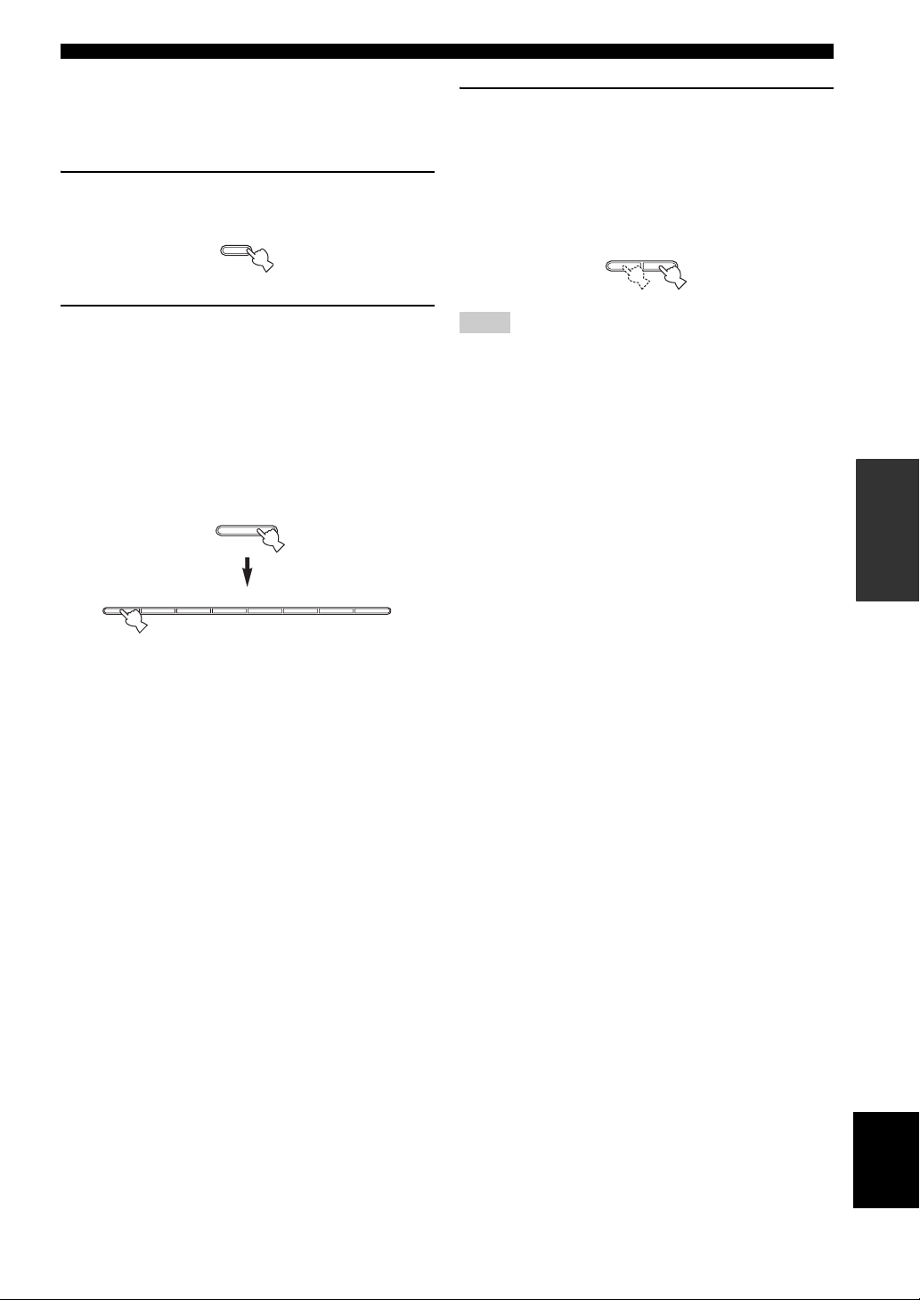
1 Press and hold MEMORY on the front panel
for more than 3 seconds.
MEMORY
MAN'L/AUTO FM
FM/AM TUNING
3 Press TUNING l / h on the front panel to
begin automatic preset tuning.
Press h to tune into higher frequencies.
Press l to tune into lower frequencies.
When automatic preset tuning is complete, the
frequency of the last preset station is shown in the
front panel display.
l
TUNING
h
2 Press A/B/C/D/E and then press one of the
preset station number buttons on the front
panel to select the preset station group and
the preset station number where the first
received station will be stored.
For example, if you select C5, the first received
station is automatically programmed to C5 and the
next received stations are sequentially programmed
to C6, C7, etc.
A/B/C/D/E
12345678
Note
Automatic preset tuning stops when the received stations have all
been stored up to E8.
OPERATION
BASIC
23
English
Page 26
FM/AM TUNING
12
20
60
26
40
16
-dB
Manual preset tuning
You can also manually store up to 40 stations (8 stations in
each of the 5 groups, A1 to E8). You can then easily recall
any preset stations by selecting the preset station numbers
where they are stored.
2
l
TUNINGH
ZONE 2 ON/OFF
ZONE CONTROL
MASTER
ON OFF
MAIN ZONE
ON/OFF
A/B/C/D/E
INPUT
12345678
BASS
PHONES
101
SPEAKERS
22
BA
3
44
55
–
3
3
+
TREBLE
101
22
3
3
44
55
+
–
4
1 Repeat steps 1 to 4 in “Automatic tuning” or
in “Manual tuning” to tune into a station.
When you tune into a station, the frequency of the
received station is shown in the front panel display.
2 Press MEMORY on the front panel.
The MEMORY indicator flashes in the front panel
display for approximately 5 seconds.
MEMORY
MAN'L/AUTO FM
FM/AM
BALANCE
101
22
3
3
44
55
R
L
h
EDIT
MEMORY
TUNING MODE
MAN'L/AUTO FM
AUTO/MAN'L
LOUDNESS
FLAT
1
–
30dB
210
3
9
48
57
6
MEMORY
Flashes
MD/TAPE MONITORPURE DIRECT
16
20
12
VOLUME
26
8
40
4
2
60
0
∞
-dB
4 Press one of the preset station number
buttons on the front panel to select a preset
station number (1 to 8) where you want to
store the station.
12345678
Note
This operation must be done within 5 seconds while the
MEMORY indicator is flashing in the front panel display.
Otherwise, the manual preset tuning process is automatically
canceled.
5 Press MEMORY on the front panel to store
the station.
6 Repeat steps 1 to 5 to store other stations.
Notes
• Any station data stored under a preset station number is cleared
when you store a new station under that preset station number.
• The reception mode (stereo or monaural) is stored along with
the station frequency.
3 Press A/B/C/D/E on the front panel
repeatedly to select a preset station group (A
to E).
The selected preset station group is shown in the front
panel display.
A/B/C/D/E
24
Page 27
FM/AM TUNING
12
20
60
26
40
16
-dB
12
20
60
26
40
16
-dB
Selecting preset stations
You can tune into the desired station simply by selecting
the preset station number where it is stored.
h
l TUNING
ZONE 2 ON/OFF
ZONE CONTROL
MASTER
ON OFF
MAIN ZONE
ON/OFF
A/B/C/D/E
INPUT
12345678
BASS
SPEAKERS
BA
101
22
3
44
55
–
PHONES
1
3
+
TREBLE
101
22
3
3
44
55
+
–
2
3
1 Press A/B/C/D/E on the front panel
repeatedly (or press A/B/C/D/E j / i on the
remote control) to select a preset station
group (A to E).
The selected preset station group is shown in the front
panel display.
A/B/C/D/E
Front panel
or
A/B/C/D/E A/B/C/D/E
2 Press one of the preset station number
buttons on the front panel (or
PRESET j / i on the remote control) to select
a preset station number (1 to 8).
The preset station number appears in the front panel
display along with the reception band and the
frequency.
12345678
Front panel
or
FM/AM
EDIT
MEMORY
TUNING MODE
MAN'L/AUTO FM
AUTO/MAN'L
BALANCE
LOUDNESS
FLAT
101
1
–
30dB
22
210
3
3
9
44
48
55
R
L
57
6
ENTER
PRESET/CH
Remote control
MD/TAPE MONITORPURE DIRECT
16
20
12
VOLUME
26
8
40
4
2
60
0
∞
-dB
Exchanging preset stations
You can exchange the assignment of two preset stations
with each other. The following procedure describes an
example where a preset station E1 is exchanged with
another preset station A5.
2,4
h
l TUNING
BALANCE
101
22
3
3
44
55
R
L
FM/AM
EDIT
MEMORY
TUNING MODE
MAN'L/AUTO FM
AUTO/MAN'L
LOUDNESS
FLAT
1
–
30dB
210
3
9
48
57
6
MEMORY
Flashes
MD/TAPE MONITORPURE DIRECT
16
20
12
VOLUME
26
8
40
4
2
60
0
∞
-dB
ZONE 2 ON/OFF
ZONE CONTROL
MASTER
ON OFF
MAIN ZONE
ON/OFF
A/B/C/D/E
INPUT
12345678
BASS
PHONES
101
SPEAKERS
22
BA
3
44
55
–
3
+
TREBLE
101
22
3
3
44
55
+
–
1 Repeat steps 1 and 2 in “Selecting preset
stations” to select a preset station E1.
2 Press EDIT on the front panel.
E1 and the MEMORY indicator flash in the front
panel display.
EDIT
3 Repeat steps 1 and 2 in “Selecting preset
stations” to select another preset station A5.
A5 and the MEMORY indicator flash in the front
panel display.
MEMORY
Flashes
4 Press EDIT on the front panel again.
E1-A5 appears in the front panel display, indicating
that the two preset station assignments have been
exchanged.
EDIT
OPERATION
BASIC
A/B/C/D/E A/B/C/D/E
ENTER
PRESET/CH
Remote control
English
25
Page 28
RADIO DATA SYSTEM (EUROPE MODEL ONLY)
RADIO DATA SYSTEM (EUROPE MODEL ONLY)
Receiving Radio Data System stations
Radio Data System is a data transmission system used by FM
stations in many countries. The Radio Data System function is
carried out among the network stations.
This unit can receive various Radio Data System data such as PS
(Program Service name), PTY (Program Type), RT (Radio Text),
CT (Clock Time), EON (Enhanced Other Networks) when
receiving Radio Data System broadcasting stations.
■ PS (Program Service name) mode
The name of the Radio Data System station being received
is displayed.
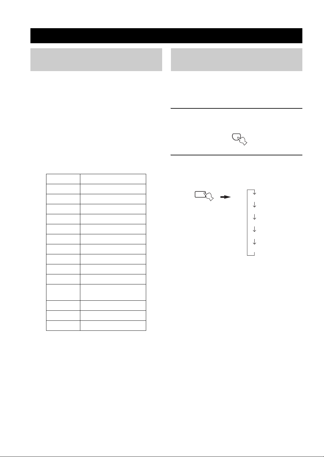
■ PTY (Program Type) mode
There are 15 program types to classify Radio Data System
stations.
NEWS News
AFFAIRS Current affairs
INFO General information
SPORT Sports
EDUCATE Education
DRAMA Drama
CULTURE Culture
SCIENCE Science
VARIED Light entertainment
POP M Pops
ROCK M Rock
M.O.R. M Middle-of-the-road music
(easy-listening)
LIGHT M Light classics
CLASSICS Serious classics
OTHER M Other music
Changing the Radio Data System mode
Four modes are available for displaying Radio Data
System data. The PS, PTY, RT and/or CT indicators that
correspond to the Radio Data System data services offered
by the station light up in the front panel display.
1 Press TUNER on the remote control to set
this unit to tuner mode.
TUNER
2 Press FREQ/TEXT repeatedly on the remote
control to display the various Radio Data
System data offered by the transmitting
station.
b
FREQ/TEXT
Remote control
PS
PTY
RT
CT
Frequency display
■ RT (Radio Text) mode
Information about the program (such as the title of the
song or name of the singer) on the Radio Data System
station being received is displayed using a maximum of 64
alphanumeric characters, including the umlaut symbol. If
other characters are used for RT data, they are displayed
with an underbar (_).
■ CT (Clock Time) mode
The current time is displayed and updated every minute.
If the data are accidentally cut off, “CT WAIT” may appear.
■ EON (Enhanced Other Networks)
See “EON function” on page 28.
26
Page 29
RADIO DATA SYSTEM (EUROPE MODEL ONLY)
Notes
• Do not press FREQ/TEXT until a Radio Data System indicator
lights up in the front panel display. You cannot change the mode
if you press the button prior to this. This is because this unit has
not finished receiving all of the Radio Data System data from
the station.
• Radio Data System data not offered by the station cannot be
selected.
• This unit cannot utilize the Radio Data System data source if
the signal received is not strong enough. In particular, the RT
mode requires a large amount of data, so it is possible that the
RT mode may not be displayed even if other Radio Data System
modes (PS, PTY, etc.) are displayed.
• Radio Data System data may not be received under poor
reception conditions. In such cases, press TUNING MODE
(AUTO/MAN’L MONO) so that the AUTO indicator
disappears from the front panel display. Although this will
change the reception mode to manual, Radio Data System data
may be displayed when you change the display to Radio Data
System mode.
• If the signal strength is weakened by external interference
during the reception of a Radio Data System station, the Radio
Data System data service may be cut off suddenly and
“...WAIT” will appear in the front panel display.
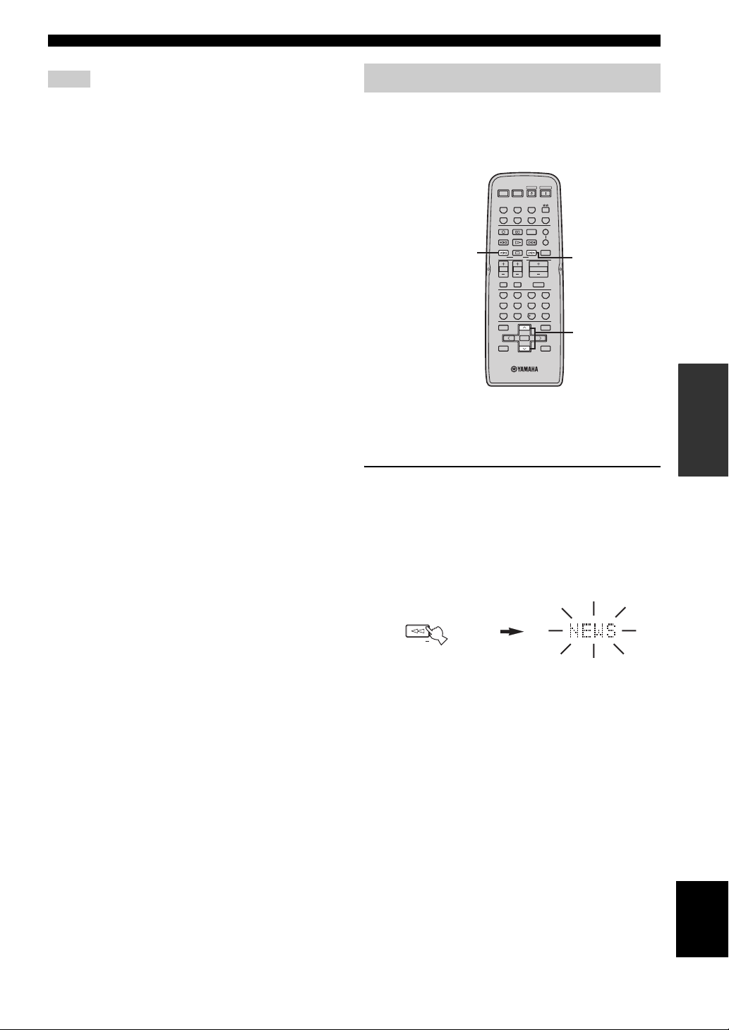
PTY SEEK function
If you select the desired program type, this unit
automatically searches all preset Radio Data System
stations that are broadcasting a program of the required
type.
POWER POWER
STANDBY
POWER
AVTV
CD
MD/TAPE
TUNER
PHONODVD
VCR
DTV/CBL
REC
CODE SET
SPEAKERS
DISC SKIP
FREQ/TEXT
MODE PTY SEEK
1
TV VOL
TV MUTE TV INPUT
BAND
A/B/C/D/E A/B/C/D/E
y
When performing this operation with the remote control, first
press TUNER to set the remote to tuner mode.
1 Press PTY SEEK MODE on the remote
control to set this unit in the PTY SEEK
mode.
The program type of the station being received or
“NEWS” flashes in the front panel display.
To exit from the PTY SEEK mode, press PTY SEEK
MODE again.
A
B
EON
SLEEP
START
VOLUME
TV CH
ENTER
PRESET/CH
3
MUTE
4321
81070965
ENT.
MENUTITLE
2
DISPLAYRETURN
OPERATION
BASIC
MODE PTY SEEK
Remote control
Flashes
English
27
Page 30
RADIO DATA SYSTEM (EUROPE MODEL ONLY)
2 Press PRESET/CH u / d on the remote
control to select the desired program type.
The selected program type appears in the front panel
display.
A/B/C/D/E A/B/C/D/E
ENTER
PRESET/CH
POP M
3 Press PTY SEEK START on the remote
control to begin searching all preset Radio
Data System stations.
The selected program type flashes and the PTY
HOLD indicator lights up in the front panel display
while searching for stations.
To cancel searching, press PTY SEEK START again.
STARTPTY SEEK
Remote control
• The unit stops searching when it finds a station
broadcasting the selected type of program.
• If the found station is not the one you desire, press
PTY SEEK START again. This unit resumes
searching for another station broadcasting the same
type of program.
PTY HOLD
Lights up
EON function
This function uses the EON data service on the Radio
Data System station network. If you select the desired
program type (NEWS, INFO, AFFAIRS or SPORT), this
unit automatically searches for all preset Radio Data
System stations that are scheduled to broadcast the
selected type of program and switches from the station
currently being received to the new station when the
broadcast starts.
POWER POWER
STANDBY
POWER
AVTV
CD
MD/TAPE
TUNER
PHONODVD
DTV/CBL
VCR
REC
CODE SET
SPEAKERS
DISC SKIP
FREQ/TEXT
MODE PTY SEEK
TV VOL
TV MUTE TV INPUT
y
When performing this operation with the remote control, first
press TUNER to set the remote to tuner mode.
Note
This function can only be used when a Radio Data System station
that offers the EON data service is being received. When such a
station is being received, the EON indicator lights up in the front
panel display.
1 Check that the EON indicator is lit in the front
panel display.
If the EON indicator is not lit up, tune into another
Radio Data System station so that the EON indicator
lights up.
A
B
EON
SLEEP
START
VOLUME
TV CH
2
MUTE
28
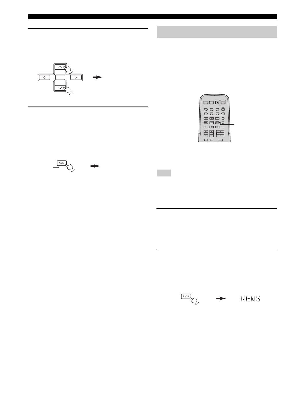
2 Press EON repeatedly on the remote control
to select the desired program type (NEWS,
INFO, AFFAIRS or SPORT).
The selected program type name appears in the front
panel display.
EON
Remote control
• If a preset Radio Data System station type starts
broadcasting the selected type of program, the unit
automatically switches from the program being
received to that program. (The EON indicator
flashes.)
• When broadcasting of the selected program ends,
the unit returns to the previous station (or another
program on the same station).
■ To cancel this function
Press EON repeatedly until no program type name is
shown in the front panel display.
Page 31

ADVANCED SETUP
12
20
60
26
40
16
-dB
■ ADVANCED SETUP menu parameters
Change the initial settings (indicated in bold under each
parameter) to reflect the needs of your listening
environment.
Factory presets PRESET
Use to reset all parameters to the factory presets.
Choices: CANCEL, RESET
• Select CANCEL if you do not want the parameters of
this unit to be initialized when you reset the factory
presets.
• Select RESET if you want all of the parameters of this
unit to be initialized when you reset the factory presets.
Notes
• This setting does not affect the parameters in the ADVANCED
SETUP menu.
• The resetting process starts next time you turn on the power of
this unit.
Remote REMOTE
Use to switch the remote control ID of this unit.
Choices: ID1, ID2
• Select ID1 to operate this unit using an alternative
code.
• Select ID2 to operate this unit using the default code.
Note
You must also make settings for the remote control (see page 30).
Tune r TU
(Asia and General models only)
Use to switch the frequency step selection according to the
frequency spacing in your area.
Choices: AM10/FM100, AM9/FM50
• North, Central and South America:
AM10/FM100 (kHz)
• Other areas: AM9/FM50 (kHz)
ADVANCED SETUP
Changing the ADVANCED SETUP menu parameters
The ADVANCED SETUP menu is displayed in the front
panel display.
y
• During the ADVANCED SETUP procedure, audio output is
muted.
• During the ADVANCED SETUP procedure, only MASTER
ON/OFF, A/B/C/D/E and the preset station number buttons (1
and 2) on the front panel are operational.
1,2,5
l
TUNING
ZONE 2 ON/OFF
ZONE CONTROL
MASTER
ON OFF
MAIN ZONE
ON/OFF
A/B/C/D/E
INPUT
12345678
BASS
101
SPEAKERS
PHONES
BA
22
3
44
55
–
3
3
+
TREBLE
101
22
3
44
55
+
–
3
2,4 3
1 Press MASTER ON/OFF on the front panel to
release it outward to the OFF position.
MASTER
ON OFF
2 Press and hold A/B/C/D/E on the front panel
and then press MASTER ON/OFF inward to
the ON position.
The power of this unit is turned on, and the
ADVANCED SETUP menu appears in the front
panel display.
A/B/C/D/E
While holding down,
press
FM/AM
EDIT
BALANCE
101
22
3
44
55
R
L
h
MEMORY
TUNING MODE
MAN'L/AUTO FM
AUTO/MAN'L
LOUDNESS
FLAT
1
–
30dB
210
3
9
48
57
6
VOLUME
40
MASTER
ON OFF
MD/TAPE MONITORPURE DIRECT
16
20
12
26
8
4
2
60
0
∞
-dB
OPERATION
ADVANCED
English
29
Page 32

ADVANCED SETUP
3 Press the preset station number buttons (1
and 2) on the front panel repeatedly to move
through the menu and select the parameter
you want to adjust.
See page 29 for a complete list of available
parameters.
1 2
4 Press A/B/C/D/E on the front panel
repeatedly to toggle between the available
parameters.
A/B/C/D/E
5 Press MASTER ON/OFF to release it outward
to the OFF position to confirm your setting.
MASTER
ON OFF
Note
The settings you made are reflected next time you turn on the
power of this unit.
Switching the remote control ID
You can select the unit you want to operate with the
remote control by switching the remote control ID.
1 Press and hold CODE SET on the remote
control and then press TUNER on the remote
control.
CODE SET
MENU
2 While holding down CODE SET on the
remote control, use the numeric buttons on
the remote control to enter the three-digit
code number listed in the table below.
CODE SET
MENU
Remote
control ID*
(this unit’s
setting)
ID1
ID2
(default setting)
Function Code number
To operate this
unit using an
alternative code.
To operate this
unit using the
default code.
POWER POWER
AVTV
CD
MD/TAPE
DTV/CBL
BAND
ENTER
A/B/C/D/E A/B/C/D/E
PRESET/CH
STANDBY
POWER
TUNER
PHONODVD
VCR
4321
81070965
ENT.
MENUTITLE
DISPLAYRETURN
801
802
30
*
When you change the remote control ID, you must switch
the remote control ID of this unit (see page 29).
When using multiple YAMAHA receivers or
amplifiers with the same default code setting, you
may unwantedly operate those components
simultaneously. In this case, set one of the alternative
codes for this unit to operate this unit separately.
Page 33

ZONE 2
ZONE 2
Connecting the Zone 2 components
This unit allows you to configure a multi-room audio and video system. The Zone 2 feature enables you to set this unit to
reproduce separate input sources in the main room and in Zone 2 (the second room) simultaneously. You can also control
this unit from the second room using the Zone 2 remote control (sold separately).
You need the following additional equipment to use the multi-room system of this unit:
• Zone 2 remote control
• An infrared signal receiver for the second room
• An infrared emitter for the main room. This emitter transmits the infrared signals sent by the Zone 2 remote control in
Zone 2 to the components in the main room.
• An amplifier and speakers for the second room
y
Some YAMAHA models are able to connect directly to the REMOTE OUT jack on the rear panel of this unit. If you own these
products, you may not need to use an infrared emitter. Up to six YAMAHA components can be connected as shown below.
REMOTE
Infrared signal
receiver
IN
This unit
REMOTE
IN
YAMAHA
component
REMOTE
OUT
IN
REMOTE
OUTOUT
YAMAHA
component
■ Multi-room configuration and connections
The following illustration shows an example of the multi-room system configuration and connections.
ZONE 2 AUDIO OUT
SPEAKERS
MONITOR OUT
DVD player
(or other components)
AUDIO IN
VIDEO IN
Infrared emitter
(Main Zone)
Main room
This unit
REMOTE OUT
MAIN
ZONE 2
y
Since there are many possible ways to connect and use this unit in a multi-room configuration, we recommend that you consult with
your nearest authorized YAMAHA dealer or service center for the Zone 2 connections that best meet your requirements.
Amplifier
Zone 2
remote control
Second room
(Zone 2)
REMOTE IN
Infrared signal
receiver
OPERATION
ADVANCED
31
English
Page 34

ZONE 2
Controlling Zone 2
You can control the input source of Zone 2 independently
of the listening conditions in the main room.
1 Press ZONE 2 ON/OFF on the front panel to
turn on Zone 2.
ZONE 2 ON/OFF
2 Press ZONE 2 CONTROL on the front panel
The ZONE 2 indicator flashes in the front panel
display.
ZONE CONTROL
3 While the ZONE 2 indicator is flashing, rotate
the INPUT selector on the front panel to
select the input source of Zone 2.
INPUT
y
• You can also select the input source by using the Zone 2 remote
control (sold separately). Press POWER on the Zone 2 remote
control to turn on Zone 2, and then press one of the input
selector buttons to select the input source.
• You can mute the sound output to Zone 2 by pressing MUTE on
the ZONE 2 remote control. Press again to restore the sound
output.
32
Page 35

Control area
REMOTE CONTROL FEATURES
REMOTE CONTROL FEATURES
■ Controlling this unit
The shaded areas below can be used to control this unit.
POWER POWER
DISC SKIP
FREQ/TEXT
STANDBY
AVTV
CD
MD/TAPE
TUNER
VCR
DTV/CBL
REC
CODE SET
EON
START
MODE PTY SEEK
TV VOL
TV CH
TV MUTE TV INPUT
BAND
ENTER
A/B/C/D/E A/B/C/D/E
PRESET/CH
VOLUME
MUTE
POWER
PHONODVD
SPEAKERS
SLEEP
MENUTITLE
DISPLAYRETURN
The buttons inside the
dotted lines control this
unit in any mode
A
B
(POWER, STANDBY,
SLEEP, the input
selector buttons,
VOLUME +/– and
MUTE).
4321
81070965
ENT.
■ Controlling other components
The shaded areas below can be used to control other
audio and video components made by YAMAHA and
other manufacturers. Each button has a different
function depending on the selected component. Select
the component you want to control by pressing one of
the input selector buttons. The name of the selected
component appears in the front panel display.
POWER POWER
The input selector
buttons switch the
function of the
component control
area below.
FREQ/TEXT
Component
control area
You can control up
to 7 different
components by
setting the
appropriate remote
control codes (see
page 35).
STANDBY
AVTV
CD
MD/TAPE
TUNER
VCR
DTV/CBL
REC
CODE SET
REC
DISC SKIP
DISC SKIP
FREQ/TEXT
START
MODE PTY SEEK
MODE PTY SEEK
TV VOL
TV CH
TV VOL
TV CH
TV MUTE TV INPUT
TV MUTE TV INPUT
BAND
ENTER
BAND
A/B/C/D/E A/B/C/D/E
A/B/C/D/E A/B/C/D/E
PRESET/CH
EON
VOLUME
PRESET/CH
POWER
PHONODVD
SPEAKERS
A
CODE SET
B
SLEEP
EON
START
MUTE
4321
81070965
ENT.
ENT.
MENUTITLE
MENUTITLE
ENTER
DISPLAYRETURN
DISPLAYRETURN
4321
81070965
OPERATION
ADVANCED
y
You can use the button to control other components
regardless of whether they are connected to this unit.
English
33
Page 36

REMOTE CONTROL FEATURES
STANDBY
POWER
CD
MD/TAPE
TUNER
PHONODVD
SLEEP
A
B
POWER POWER
REC
CODE SET
VOLUME
DISC SKIP
EON
FREQ/TEXT
START
MODE PTY SEEK
TV MUTE TV INPUT
AVTV
VCR
DTV/CBL
SPEAKERS
TV VOL
TV CH
MUTE
MENUTITLE
BAND
A/B/C/D/E A/B/C/D/E
PRESET/CH
4321
81070965
ENT.
DISPLAYRETURN
TV MUTE TV INPUT
ENTER
Controlling other components
In addition to controlling this unit, you can also control
other audio and video components made by YAMAHA
and other manufacturers using the supplied remote
control. To control other components, you must set the
appropriate remote control codes.
1
2
3
4
5
6
7
8
9
0
A
B
C
D
DVD player VCR
1
1 AV PO WE R
2 TV POWER
3 ll
Power *
TV power TV power TV power
Search backward Search backward
hh Search forward Search forward
Power *
Digital TV/
Cable TV
1
Power *
VCR search
backward
VCR search
forward
TV CD player Tape deck MD recorder Tuner
1
VCR power
1
Power *
VCR search
backward
VCR search
forward
Power *
1
Power *
1
Power *
TV power TV power TV power TV power
Search backward Search backward Search backward
Search forward Search forward Search forward
1
b Skip backward Skip backward Direction A Skip backward
a Skip forward Skip forward Direction B Skip forward
REC/
DISC SKIP
Disc skip Rec VCR rec VCR rec Disc skip Rec Rec
s Stop Stop VCR stop VCR stop Stop Stop Stop
e Pause Pause VCR pause VCR pause Pause Deck A/B Pause
h Play Play VCR play VCR play Play Play Play
4 TV VOL +
TV volume + TV volume + TV volume + Volume + TV volume + TV volume + TV volume + TV volume +
TV VOL – TV volume – TV volume – TV volume – Volume – TV volume – TV volume – TV volume – TV volume –
5 TV CH +
TV CH –
6 TV MUTE
7 TITLE
8 ENTER
TV channel + Channel + Channel + Channel + TV channel + TV channel + TV channel + TV channel +
TV channel – Channel – Channel – Channel – TV channel – TV channel – TV channel – TV channel –
TV mute TV mute TV mute Mute TV mute TV mute TV mute TV mute
Title Title Title Title Band
Menu enter Menu select Menu select
PRESET/CH uMenu up Menu up Menu up
PRESET/CH dMenu down Menu down Menu down
A/B/C/D/E j Menu left Menu left Menu left
A/B/C/D/E i Menu right Menu right Menu right
9 RETURN
0 TV INPUT
A 1-9, 0, +10
B ENT.
C MENU
D DISPLAY
*1
This button functions only when the original remote control of the component has the POWER button.
*2
These buttons function for Europe model only.
34
Return Return Return Return
TV input TV input TV input Input TV input TV input TV input TV input
Numeric buttons Numeric buttons Numeric buttons Numeric buttons Numeric buttons Numeric buttons
Enter Enter/recall
Enter/
numeric button
Index
Menu Menu Menu
Display Display Display Display Display
1
Power *
PTY MODE *
PTY START *
FREQ/TEXT *
2
EON *
Preset up
(1 to 8)
Preset down
(1 to 8)
Preset down
(A to E)
Preset up
(A to E)
Preset stations (1-8)
2
2
2
Page 37

REMOTE CONTROL FEATURES
Setting remote control codes
You can control other components by setting the
appropriate remote control codes. Codes can be set up for
each input source. For a complete list of available remote
control codes, refer to “LIST OF REMOTE CONTROL
CODES” at the end of this manual.
The following table show the default component category
(library) and the remote control code for each input
source.
Remote control code default settings
Default
Input
source
component
category
Manufacturer
(library)
CD CD YAMAHA 199
MD/TAPE TAP E YA MA HA 49 9
DVD DVD YAMAHA 699
DTV/CBL*
———
VCR ———
PHONO ———
———
*
You can only set the TV remote control codes for the DTV/
CBL button. However, other remote control codes can be set
for any input selector buttons except DTV/CBL.
Note
You may not be able to operate your other YAMAHA
components even if the YAMAHA remote control code is
initially set as listed above. In this case, try setting other
YAMAHA remote control codes.
Default
YAMAHA
code
1 Press and hold CODE SET on the remote
control and then press one of the input
selector buttons on the remote control to
select the input source you want to set up.
CODE SET
MENU
POWER POWER
CD
MD/TAPE
DTV/CBL
STANDBY
POWER
AVTV
TUNER
PHONODVD
VCR
Note
You must press and hold CODE SET throughout this operation.
2 While holding down CODE SET on the
remote control, use the numeric buttons on
the remote control to enter the three-digit
remote control code for the selected input
source.
When the setting succeeds, “PRESET OK” appears;
however, when it does not, “PRESET NG” appears in
the front panel display.
To reset the code, enter the default code for each
input source listed in the remote control code default
settings table.
4321
81070965
CODE SET
MENU
BAND
Notes
• If the manufacturer of your component has more than one code,
try setting each of them until you find the correct one.
• You can only assign one remote control code to each input
selector button.
ENTER
A/B/C/D/E A/B/C/D/E
PRESET/CH
ENT.
MENUTITLE
DISPLAYRETURN
OPERATION
ADVANCED
35
English
Page 38

TROUBLESHOOTING
TROUBLESHOOTING
Refer to the chart below if this unit does not function properly. If the problem you are experiencing is not listed below or
if the instructions below do not help, set this unit to the standby mode, disconnect the power cord, and contact the nearest
authorized YAMAHA dealer or service center.
■ General
Problem Cause Remedy
This unit fails to turn
on.
No sound Incorrect input or output cable
The sound suddenly
goes off.
Only the speaker on
one side can be
heard.
There is a lack of bass
and no ambience.
A “humming” sound
can be heard.
The volume level is
low while playing a
record.
The volume level
cannot be increased,
or the sound is
distorted.
The power supply cord is not connected or
the plug is not completely inserted.
The impedance setting is incorrect. Set the impedance to match your speakers.
The protection circuitry has been activated
because of a short circuit, etc.
The IMPEDANCE SELECTOR switch on
the rear panel is not set to either end.
This unit has been exposed to a strong
external electric shock (such as lightning
or strong static electricity).
connections.
No appropriate input source has been
selected.
The SPEAKERS A/B switches are not set
properly.
Speaker connections are not secure. Secure the connections.
The protection circuitry has been activated
because of a short circuit, etc.
Incorrect cable connections. Connect the cables properly. If the problem persists,
Incorrect setting for the BALANCE
control.
The + and – wires are connected in
reverse at the amplifier or the speakers.
Incorrect cable connections. Connect the audio plugs firmly. If the problem
No connection from the turntable to the
GND terminal.
The record is being played on a turntable
with an MC cartridge.
The component connected to the MD/
TAPE OUT jacks of this unit is turned off.
Connect the power supply cord firmly.
Check that the speaker wires are not touching each
other and then turn the power of this unit back on.
Set the IMPEDANCE SELECTOR switch to either
end when the power of this unit is turned off.
Set this unit to the standby mode, disconnect the
power supply cord, plug it back in after 30 seconds,
then use it normally.
Connect the cables properly. If the problem persists,
the cables may be defective.
Select an appropriate input source with the INPUT
selector on the front panel (or one of the input
selector buttons on the remote control).
Turn on the corresponding SPEAKERS A or
SPEAKERS B.
Check that the IMPEDANCE SELECTOR setting is
correct.
Check that the speaker wires are not touching each
other and then turn the power of this unit back on.
the cables may be defective.
Set the BALANCE control to the appropriate
position.
Connect the speaker wires to the correct + and –
phase.
persists, the cables may be defective.
Make the GND connection between the turntable and
this unit.
The turntable should be connected to this unit through
the MC head amplifier.
Turn on the power of the component.
See
page
—
11
11
11
—
10
15
15
11
11
11
10
16
11
10
10
—
—
36
Page 39

TROUBLESHOOTING
The sound is
degraded when
listening with the
headphones
connected to the CD
player or the tape
deck connected to
this unit.
The sound level is
low.
Using the BASS,
TREBLE, BALANCE
and LOUDNESS
controls does not
affect the tonal
quality.
The power of this unit is turned off, or this
unit is set to the standby mode.
The LOUDNESS control is functioning. Set the LOUDNESS control to the FLAT position.
The PURE DIRECT button is turned on. The PURE DIRECT button must be turned off to use
Turn on the power of this unit.
those controls.
■ Tuner
Problem Cause Remedy
FM stereo
reception is
noisy.
There is
distortion, and
clear reception
cannot be
obtained even
with a good FM
antenna.
FM
The desired
station cannot
be tuned in
with the
automatic
tuning method.
Previously
preset stations
can no longer
be tuned in.
The desired
station cannot
be tuned in
with the
automatic
tuning method.
AM
There are
continuous
crackling and
hissing noises.
There are
buzzing and
whining noises.
The particular characteristics of the FM
stereo broadcasts being received may
cause this problem when the transmitter is
too far away or the antenna input is poor.
There is multipath interference. Adjust the antenna position to eliminate the multipath
The signal is too weak. Try using a high-quality directional FM antenna.
This unit has been disconnected for a long
period.
The signal is weak or the antenna
connections are loose.
The noises may result from lightning,
fluorescent lamps, motors, thermostats or
other electrical equipment.
A TV set is being used nearby. Move this unit away from the TV set.
Check the antenna connections.
Try using a high-quality directional FM antenna.
Try using the manual tuning method.
interference.
Try using the manual tuning method.
Preset the stations again.
Tighten the AM loop antenna connections and orient
it for the best reception.
Try using the manual tuning method.
Try using an outdoor antenna and a ground wire.
This will help somewhat, but it is difficult to
eliminate all noise.
14
16
16
See
page
12
21
—
12
21
22
—
21
—
—
INFORMATION
ADDITIONAL
37
English
Page 40

TROUBLESHOOTING
■ Remote control
Problem Cause Remedy
The remote control
does not work nor
function properly.
Wrong distance or angle. The remote control will function within a maximum
Direct sunlight or lighting (from an
inverter type of fluorescent lamp, etc.) is
striking the remote control sensor of this
unit.
The batteries are weak. Replace all batteries.
The remote control ID and this unit’s ID
do not match.
The remote control code was not correctly
set.
Even if the remote control code is
correctly set, there are some models that
do not respond to the remote control.
range of 6 m (19.7 ft) and no more than 30 degrees
off-axis from the front panel.
Reposition this unit.
Switch the remote control ID or this unit’s ID.
Try setting another code of the same manufacturer
using “LIST OF REMOTE CONTROL CODES” at
the end of this manual.
Use the supplied remote control for the components.
See
page
9
—
9
29, 30
35
—
38
Page 41

SPECIFICATIONS
SPECIFICATIONS
AUDIO SECTION
• Minimum RMS Output Power
(8 Ω , 20 Hz to 20 kHz, 0.04% THD) ...................... 75 W + 75 W
• Dynamic Power (IHF)
(8/6/4/2 Ω) ..................................................... 105/125/150/178 W
• Maximum Output Power [Europe model only]
(1 kHz, 0.7% THD, 4 Ω) .................................................... 105 W
• IEC Output Power [Europe model only]
(1 kHz, 0.04% THD, 8 Ω) .................................................... 84 W
• Power Band Width
(0.08% THD, 35 W, 8 Ω) .................................... 10 Hz to 50 kHz
• Damping Factor (SPEAKERS A)
20 Hz to 20 kHz, 8 Ω ................................................. 150 or more
• Maximum Output Power (EIAJ)
[Asia and General models only]
(1 kHz, 10% THD, 8 Ω) ..................................................... 115 W
• Maximum Input Signal
PHONO (1 kHz, 0.04% THD) .............................. 70 mV or more
CD, etc. (1 kHz, 0.04% THD) ................................ 2.2 V or more
• Frequency Response
CD, etc. (20 Hz to 20 kHz) ........................................... 0 ± 0.5 dB
CD, etc. PURE DIRECT ON (10 Hz to 100 kHz) ........ 0 ± 1.0 dB
• RIAA Equalization Deviation
PHONO ............................................................................ ± 0.5 dB
• Total Harmonic Distortion
PHONO to OUT (REC)
(20 Hz to 20 kHz, 3 V) ........................................... 0.02% or less
CD, etc. to SPEAKERS
(20 Hz to 20 kHz, 35 W, 8 Ω) ................................. 0.02% or less
• Signal to Noise Ratio (IHF-A Network)
PHONO (5 mV input shorted) ............................... 82 dB or more
CD, etc. (185 mV input shorted) ......................... 108 dB or more
• Residual Noise (IHF-A Network)
PURE DIRECT ON .......................................................... 100 µV
• Gain Tracking Error (0 to –60 dB) ................................ 2 dB or less
• Input Sensitivity/Input Impedance
PHONO .................................................................. 3.0 mV/47 kΩ
CD, etc. ................................................................. 185 mV/47 kΩ
• Output Level/Output Impedance
OUT (REC) ............................................... 185 mV/1.2 kΩ or less
SUB WOOFER OUTPUT ............................... 4 V/1.2 kΩ or less
ZONE 2 OUT ........................................... 185 mV/1.2 kΩ or less
• Headphone Output/Impedance
(Input 1 kHz, 185 mV, 8 Ω , 0.015% THD)
CD, etc. .................................................................... 0.47 V/390 Ω
• Channel Separation
CD, etc. (5.1 kΩ input shorted, 1/10 kHz) ........ 65/50 dB or more
• Tone Control Characteristics
BASS
Boost/Cut (20 Hz) ........................................................... ±10 dB
Turnover Frequency ........................................................ 350 Hz
TREBLE
Boost/Cut (20 kHz) ......................................................... ±10 dB
Turnover Frequency ....................................................... 3.5 kHz
• Continuous Loudness Control
Attenuation (1 kHz) ........................................................... –30 dB
VIDEO SECTION
• Video Signal Type
[U.S.A., Canada and General models] ................................ NTSC
[Other models] ....................................................................... PAL
• Signal to Noise Ratio ................................................ 50 dB or more
• Frequency Response (MONITOR OUT)
Composite ................................................. 5 Hz to 10 MHz, –3 dB
FM SECTION
• Tuning Range
[U.S.A. and Canada models] ........................... 87.5 to 107.9 MHz
[Asia and General models] ........ 87.5/87.50 to 107.9/108.00 MHz
[Other models] ............................................ 87.50 to 108.00 MHz
• Usable Sensitivity (IHF)........................................ 1.0 µV (11.2 dBf)
• Signal to Noise Ratio (IHF)
Mono/Stereo .............................................................. 76 dB/70 dB
• Harmonic Distortion (1 kHz)
Mono/Stereo ................................................................ 0.2%/0.3%
• Stereo Separation (1 kHz) ....................................................... 45 dB
• Frequency Response ........................... 20 Hz to 15 kHz, +0.5/–2 dB
AM SECTION
• Tuning Range
[U.S.A. and Canada models] .............................. 530 to 1710 kHz
[Asia and General models] ................. 530/531 to 1710/1611 kHz
[Other models] ................................................... 531 to 1611 kHz
• Usable Sensitivity ............................................................. 300 µV/m
GENERAL
• Power Supply
[U.S.A. and Canada models] .............................. AC 120 V, 60 Hz
[Asia model] ....................................AC 220/230-240 V, 50/60 Hz
[General model] ................ AC 110/120/220/230-240 V, 50/60 Hz
[Australia model] ............................................... AC 240 V, 50 Hz
[Europe model] ................................................... AC 230 V, 50 Hz
• Power Consumption .............................................................. 180 W
• Standby Power Consumption ................................................. 0.1 W
• Maximum Power Consumption [General model only]
(8 Ω , 1 kHz, 10% THD) .................................................... 400 W
•AC Outlets
[Australia model] ............................... 1 (Total 100 W maximum)
[General model] ................................... 2 (Total 50 W maximum)
[Other models] ................................... 2 (Total 100 W maximum)
• Dimensions (W x H x D) ................................ 435 x 151 x 308 mm
(17-1/8” x 5-15/16” x 12-1/8”)
• Weight ............................................................. 8.7 kg (19 lbs. 3 oz.)
* Specifications are subject to change without notice.
INFORMATION
ADDITIONAL
English
39
Page 42

ATTENTION: VEUILLEZ LIRE CE QUI SUIT AVANT D’UTILISER L’APPAREIL.
ATTENTION: VEUILLEZ LIRE CE QUI SUIT AVANT D’UTILISER
L’APPAREIL.
1
Pour utiliser l’appareil au mieux de ses possibilités, lisez attentivement
ce mode d’emploi. Conservez-le soigneusement pour référence.
2 Installez cet appareil audio dans un endroit bien aéré, frais,
sec et propre – à l’abri de la lumière directe du soleil, des
sources de chaleur ou de vibration, des poussières, de
l’humidité et du froid. Ménagez un espace libre d’au moins
30 cm au-dessus, 20 cm sur la gauche et la droite et 20 cm à
l’arrière de l’appareil pour qu’il soit bien ventilé.
3
Placez l’appareil loin des équipements, moteurs et
transformateurs électriques, pour éviter les ronflements parasites.
4 N’exposez pas l’appareil à des variations brutales de
température, ne le placez pas dans un environnement très
humide (par exemple dans une pièce contenant un
humidificateur) car cela peut entraîner la condensation
d’humidité à l’intérieur de l’appareil qui elle-même peut être
responsable de secousse électrique, d’incendie, de dommage à
l’appareil ou de blessure corporelle.
5 Evitez d’installer l’appareil dans un endroit où des objets
peuvent tomber, ainsi que là où l’appareil pourrait être exposé
à des éclaboussures ou des gouttes d’eau. Sur le dessus de
l’appareil, ne placez pas:
– D’autres appareils qui peuvent endommager la surface de
l’appareil ou provoquer sa décoloration.
– Des objets se consumant (par exemple, une bougie) qui
peuvent être responsables d’incendie, de dommage à
l’appareil ou de blessure corporelle.
– Des récipients contenant des liquides qui peuvent être à
l’origine de secousse électrique ou de dommage à l’appareil.
6 Ne couvrez pas l’appareil d’un journal, d’une nappe, d’un
rideau, etc. car cela empêcherait l’évacuation de la chaleur.
Toute augmentation de la température intérieure de l’appareil
peut être responsable d’incendie, de dommage à l’appareil ou
de blessure corporelle.
7 Ne branchez pas la fiche du cordon d’alimentation de
l’appareil sur une prise secteur aussi longtemps que tous les
raccordements n’ont pas été effectués.
8 Ne pas faire fonctionner l’appareil à l’envers. Il risquerait de
chauffer et d’être endommagé.
9 N’exercez aucune force excessive sur les commutateurs, les
boutons et les cordons.
10
Pour débrancher la fiche du cordon d’alimentation au niveau de
la prise secteur, saisissez la fiche et ne tirez pas sur le cordon.
11
Ne nettoyez pas l’appareil au moyen d’un solvant chimique, ce qui
pourrait endommager la finition. Utilisez un chiffon sec et propre.
12 N’alimentez l’appareil qu’à partir de la tension prescrite.
Alimenter l’appareil sous une tension plus élevée est
dangereux et peut être responsable d’incendie, de dommage à
l’appareil ou de blessure corporelle. YAMAHA ne saurait être
tenue responsable des dommages résultant de l’alimentation
de l’appareil sous une tension autre que celle prescrite.
13 Pour éviter tout dommage dû à la foudre lors d’orages,
débranchez le cordon d’alimentation secteur et les antennes
extérieures de la prise secteur.
14 Ne tentez pas de modifier ni de réparer l’appareil. Consultez
le service YAMAHA compétent pour toute réparation qui
serait requise. Le coffret de l’appareil ne doit jamais être
ouvert, quelle que soit la raison.
15
Si vous envisagez de ne pas vous servir de l’appareil pendant une
longue période (par exemple, pendant les vacances), débranchez
la fiche du cordon d’alimentation au niveau de la prise secteur.
16 Installez l’appareil près de la prise secteur et à un endroit tel
que la fiche secteur soit facilement accessible.
17 Lisez la section intitulée “GUIDE DE DÉPANNAGE” où
figurent une liste d’erreurs de manipulation communes avant
de conclure que l’appareil présente une anomalie de
fonctionnement.
18 Avant de déplacer l’appareil, appuyez sur MASTER ON/OFF
pour le faire ressortir sur la position OFF, et débranchez la
fiche du cordon d’alimentation secteur de la prise murale.
19 VOLTAGE SELECTOR
(Modèles pour l’Asie et modèle standard seulement)
Le commutateur VOLTAGE SELECTOR placé sur le panneau
arrière de cet appareil doit être convenablement positionné
AVANT de brancher la fiche du cordon d’alimentation secteur.
Les tensions d’alimentation possibles sont:
Modèle standard.........110/120/220/230–240 V CA, 50/60 Hz
Modèle pour l’Asie .................. 220/230–240 V CA, 50/60 Hz
AVERTISSEMENT
POUR RÉDUIRE LES RISQUES D’INCENDIE OU
DE SECOUSSE ÉLECTRIQUE, N’EXPOSEZ PAS
CET APPAREIL À LA PLUIE OU À L’HUMIDITÉ.
Tant que l’appareil est raccordé à la prise secteur, il
reste connecté au secteur même si vous le mettez hors
tension avec MASTER ON/OFF, ou avec MAIN
ZONE ON/OFF et ZONE2 ON/OFF. Dans cet état,
l’appareil est conçu pour consommer une très faible
quantité de courant.
Page 43

TABLE DES MATIÉRES
INTRODUCTION
PARTICULARITÉS .............................................. 2
ACCESSOIRES FOURNIS ................................... 2
COMMANDES ET FONCTIONS ........................ 3
Face avant .................................................................. 3
Afficheur de la face avant.......................................... 5
Panneau arrière .......................................................... 6
Boîtier de télécommande ...........................................7
Mise en place des piles dans le boîtier de
télécommande........................................................ 9
Utilisation du boîtier de télécommande..................... 9
PRÉPARATIONS
RACCORDEMENTS........................................... 10
Raccordement des enceintes .................................... 11
Raccordement des antennes AM et FM................... 12
Raccordement du cordon d’alimentation ................. 14
Mise sous tension et hors tension de l’appareil ....... 14
OPÉRATIONS DE BASE
LECTURE ET ENREGISTREMENT ............... 15
Lecture d’une source................................................ 15
Réglage de la qualité du son ....................................16
Enregistrement d’une source ................................... 17
Utilisation de la minuterie de mise hors service...... 18
Cette touche coupe les sons ..................................... 19
SYNTONISATION FM/AM................................ 20
Syntonisation automatique....................................... 20
Syntonisation manuelle............................................ 21
Mise en mémoire automatique des fréquences ........22
Mise en mémoire manuelle...................................... 24
Choix d’une présélection ......................................... 25
Échange des fréquences ........................................... 25
RADIO DATA SYSTEM (MODÈLE POUR
L’EUROPE SEULEMENT) ............................ 26
Réception des stations Radio Data System.............. 26
Sélection du mode Radio Data System.................... 26
Service PTY SEEK.................................................. 27
Service EON ............................................................ 28
OPÉRATIONS DÉTAILLÉES
RÉGLAGES APPROFONDIS.............................29
Modification des paramètres du menu
ADVANCED SETUP .........................................29
Commutation du numéro d’identification de la
télécommande...................................................... 30
ZONE 2 ..................................................................31
Raccordements des appareils Zone 2....................... 31
Commandes Zone 2 ................................................. 32
PARTICULARITÉS DE LA
TÉLÉCOMMANDE .........................................33
Section des commandes...........................................33
Commande des autres appareils............................... 34
Enregistrement des codes de commande ................. 35
INFORMATIONS COMPLÉMENTAIRIES
GUIDE DE DÉPANNAGE...................................36
CARACTÉRISTIQUES TECHNIQUES............39
PRÉPARATIONSINTRODUCTION
OPÉRATIONS
DE BASE
OPÉRATIONS
DÉTAILLÉES
COMPLÉMENTAIRIES
INFORMATIONS
Français
1
Page 44

PARTICULARITÉS
\
PARTICULARITÉS
Amplificateur intégré à 2 voies
◆ Puissance de sortie minimum efficace
75 W +75 W (8 Ω), 0,04% DHT, 20 Hz à 20 kHz
◆ Puissance ultra-dynamique, capacité d’attaque à basse
impédance
Syntoniseur AM/FM perfectionné
◆ Présélection aléatoire de 40 fréquences
◆ Mise en mémoire automatique des fréquences
◆ Capacité d’échange des stations présélectionnées
Autres particularités
◆ Commutateur PURE DIRECT pour la reproduction la
plus fidèle possible d’une source sonore
◆ Contrôle variable de l’intensité sonore en continu
◆ Minuterie de mise hors service
◆ Commande à distance possible
◆ Zone 2 Commande à distance (vendue séparément)
possible
◆ Service d’installation client Zone 2
◆ Touches de syntonisation Radio Data System
(Modèle pour l’Europe seulement)
• Le symbole y appelle votre attention sur un conseil d’utilisation.
• Certaines actions peuvent être commandées au moyen des touches de panneau de commande de l’appareil ou de celles de la
télécommande. Lorsque le nom d’une touche du panneau de commande de l’appareil diffère de celui de la télécommande, celui de la
télécommande est donné entre parenthèses.
• Ce mode d’emploi a été imprimé avant la fabrication de l’appareil. Les caractéristiques et la présentation ont pu être modifiées à fin
d’amélioration, etc. En cas de divergence entre le mode d’emploi et l’appareil, ce dernier prime.
ACCESSOIRES FOURNIS
Veuillez vous assurer que vous possédez bien les postes suivants.
Boîtier de télécommande
POWER POWER
STANDBY
POWER
AVTV
CD
MD/TAPE
TUNER
PHONODVD
VCR
DTV/CBL
REC
CODE SET
SPEAKERS
PRESET/CH
A
B
EON
SLEEP
START
VOLUME
MUTE
4321
81070965
ENT.
MENUTITLE
ENTER
DISPLAYRETURN
DISC SKIP
FREQ/TEXT
MODE PTY SEEK
TV VOL
TV CH
TV MUTE TV INPUT
BAND
A/B/C/D/E A/B/C/D/E
Piles (x2)
(AA, R6, UM-3)
Antenne intérieure FM
(Modèles pour les ÉtatsUnis, le Canada et modèle
standard seulement)
Antenne cadre AM
Antenne intérieure FM
(Modèles pour l’Europe
et l’Australie)
2
Page 45

Face avant
12
20
60
26
40
16
-dB
COMMANDES ET FONCTIONS
COMMANDES ET FONCTIONS
INTRODUCTION
512 43870A6CB9
ZONE 2 ON/OFF
ZONE CONTROL
MASTER
ON OFF
MAIN ZONE
ON/OFF
INPUT
PHONES
A/B/C/D/E
12345678
BA
BASS
101
22
3
3
44
55
+
–
SPEAKERS
GFEHIJKLM
1 MASTER ON/OFF
Appuyez vers la position ON pour mettre cet appareil sous
tension. Appuyez à nouveau pour le ramener hors de la
position OFF et l’éteindre.
Voir page 14 pour plus de détails
Remarque
Même éteint, cet appareil continue à consommer de l’électricité
pour entretenir la mémoire.
Secours de la mémoire
Le circuit de secours de la mémoire empêche de perdre
les données enregistrées. Toutefois, toutes les données
enregistrées seront perdues si l’appareil est débranché
pendant plus d’une semaine.
2 MAIN ZONE ON/OFF
Cette touche Main Zone met l’appareil en service ou en
veille.
Voir page 14 pour plus de détails.
Remarques
• Cette touche n’agit que lorsque MASTER ON/OFF est en
position ON.
• En veille, l’appareil consomme une faible quantité d’électricité
de manière à être en mesure de recevoir les signaux infrarouges
qui peuvent être émis par le boîtier de télécommande.
l
TUNING
h
MEMORY
TUNING MODE
MAN'L/AUTO FM
AUTO/MAN'L
DISPLAY
LOUDNESS
FLAT
1
–
30dB
210
3 9
48
57
6
VOLUME
MD/TAPE MONITORPURE DIRECT
16
20
12
26
40
60
∞
8
4
2
0
-dB
TREBLE
101
22
3
3
44
55
+
–
FM/AM
EDIT
BALANCE
101
22
3
3
44
55
R
L
(Modèle pour l’Europe)
3 ZONE 2 ON/OFF
Appuyez sur Zone 2 ou la positionner sur le mode de
veille. Lorsque la touche Zone 2 est allumée, les signaux
sont envoyés vers les prises ZONE 2 OUT.
Remarque
Cette touche n’agit que lorsque MASTER ON/OFF est en
position ON.
4 ZONE CONTROL
Appuyez pour régler la source d’entrée de Zone 2.
Remarques
• Cette touche est opérationnelle si Zone 2 est activé.
• Si vous appuyez sur cette touche, le témoin ZONE 2 de la
fenêtre du panneau avant clignote pendant environ 5 secondes.
Sélectionnez la source d’entrée de Zone 2 pendant que le
témoin clignote.
• Vous pourrez régler sur la station présélectionnée si TUNER est
la source d’entrée de Zone 2.
5 Capteur de télécommande
Il reçoit les signaux émis par le boîtier de télécommande.
Remarque
Commute la télécommande ID entre ID1 et ID2 en cas
d’utilisation de récepteurs ou amplificateurs YAMAHA multiples
(reportez-vous aux pages 29 et 30).
6 Afficheur de la face avant
Il fournit des informations relatives à l’état de l’appareil.
D
Français
3
Page 46

COMMANDES ET FONCTIONS
7 EDIT
Echange l’assignation de deux stations présélectionnées
lorsque TUNER est sélectionné comme source d’entrée
(voir page 25).
8 FM/AM
Commute la bande de fréquence de réception AM et FM
lorsque TUNER est sélectionné comme source d’entrée
(voir page 20).
9 TUNING l / h
Sélectionne la fréquence de syntonisation lorsque TUNER
est sélectionné comme source d’entrée (voir page 20).
0 TUNING MODE
Commute le mode de syntonisation automatique
(le témoin AUTO est alors allumé) et manuelle (le témoin
AUTO est alors éteint) lorsque TUNER est sélectionné
comme source d’entrée.
A MEMORY
Cette touche met une fréquence en mémoire (voir page
24).
Cette touche règle l’appareil en mode de syntonisation
automatique (voir page 22).
B PURE DIRECT et témoin
Permet de restituer le son le plus pur possible lors de
l’écoute d’une source. Le témoin au-dessus de la touche
s’allume lorsque la fonction est activée (voir page 16).
C MD/TAPE MONITOR
Permet d’écouter le son lu sur l’appareil relié aux prises
MD/TAPE sur le panneau arrière de cet appareil.
Lorsque la platine à cassette est utilisée pour
l’enregistrement, le son enregistré peut être contrôlé.
Le témoin MD/TAPE MON sur le panneau avant s’allume
lorsque la fonction est activée.
Remarques
• Lorsque cette fonction est activée (le témoin est allumé),
MD/TAPE ne peut pas être sélectionné avec le sélecteur
INPUT.
• Pour écouter la source sélectionnée avec le sélecteur INPUT,
appuyez une nouvelle fois dessus pour désactiver la fonction
(le témoin s’éteint).
• Lorsque MD/TAPE est sélectionné avec le sélecteur INPUT,
cette fonction ne sera pas activée même en appuyant sur la
touche MD/TAPE MONITOR.
D VOLUME
Ces touches augmentent ou diminuent le niveau sonore.
Remarque
Elle est sans effet vis-à-vis du niveau OUT (REC).
E Sélecteur INPUT
Ce bouton assure la sélection de la source que vous
désirez écouter ou regarder.
F A/B/C/D/E
Sélectionne le groupe de stations présélectionnées (A à E)
lorsque TUNER est sélectionné comme source d’entrée
(voir page 23).
G Prise PHONES
Fournit les signaux audio destinés à l’écoute au casque.
Remarque
Appuyez SPEAKERS A/B de manière que les témoins
SP A/B s’éteint avant de raccorder les casques à la prise
PHONES.
H SPEAKERS A/B
Les enceintes reliées aux prises SPEAKERS A et/ou
SPEAKERS B placées sur le panneau arrière sont mises
en service ou hors service chaque fois que vous appuyez
sur la touche correspondante (voir page 15).
I BASS
Augmente ou diminue la réponse dans les basses
fréquences. La position 0 produit une fidélité uniforme
(voir page 16).
J TREBLE
Augmente ou diminue la réponse dans les hautes
fréquences. La position 0 produit une fidélité uniforme
(voir page 16).
K BALANCE
Équilibre le son fourni par les enceintes gauche et droite
pour compenser le déséquilibre dû à la disposition des
enceintes ou à la configuration de la pièce (voir page 16).
L LOUDNESS
Retient toute la gamme des sons à bas volume pour
compenser la perte de sensibilité de l’oreille humaine au
niveau des hautes et basses fréquences lorsque le volume
est réduit (voir page 16).
M Touches indiquant les numéros de stations
présélectionnées (1 à 8)
Sélectionne le numéro de station présélectionnée (1 à 8)
lorsque TUNER est sélectionné comme source d’entrée
(voir page 25).
4
Page 47

Afficheur de la face avant
AB0
COMMANDES ET FONCTIONS
12 5 6 7 839
SP
A B
DVD VCR CD TUNER PHONO
ZONE2 ZONE3
DTV/CBL
4
MD/TAPE
MD/TAPE
MON
1 Témoins SP (SPEAKERS) A/B
Ces témoins s’allument en fonction du jeu d’enceintes
choisi.
Les deux témoins sont éclairés lorsque les deux jeux
d’enceintes sont sélectionnés.
2 Témoin ZONE 2
S’allume lorsque Zone 2 est activé.
3 Témoins des sources
S’allume quand l’appareil est dans le mode correspondant.
4 MD/TAPE MON (MONITOR) témoin
Ce témoin s’allume lorsque la fonction de contrôle
MD/TAPE est active.
5 Témoin MEMORY
Clignote environ 5 secondes après une pression sur
MEMORY sur la face avant. Lorsque l’indicateur
MEMORY clignote, mémorisez la fréquence affichée dans
la mémoire avec A/B/C/D/E et une des touches de stations
présélectionnées sur la face avant.
6 Témoin AUTO
S’allume quand l’appareil est en mode de syntonisation
automatique.
7 Témoin STEREO
Ce témoin s’éclaire lorsque l’appareil reçoit un signal
stéréophonique FM puissant alors que le témoin AUTO est
éclairé.
MEMORY AUTO
TUNED STEREO
SLEEP
MUTE
HOLDPTY
EON
PTY
PS
RT
CT
8 Témoin SLEEP
Ce témoin s’allume lorsque la minuterie de mise hors
service est active.
9 Témoin MUTE
Ce témoin clignote lorsque la fonction (MUTE) est en
service.
0 Afficheur multifonction
Affiche les informations de réglage ou de changement de
paramètres.
A Témoin TUNED
Ce témoin s’éclaire lorsque l’appareil est accordé sur une
station.
■ Modèle pour l’Europe seulement
B Témoins Radio Data System
Le témoin en forme de carré à côté du nom de chaque
Système de données radio s’allume lorsque le système
correspondant est sélectionné.
Témoin PTY HOLD
S’allume pendant une recherche de stations en mode
PTY SEEK.
Témoin EON
S’éclaire lorsque la station Radio Data System captée
offre le service EON.
INTRODUCTION
Français
5
Page 48

COMMANDES ET FONCTIONS
Panneau arrière
1234
5
(Modèle standard)
AUDIOVIDEOTUNER
DVD
GND
DTV/
CBL
AM
ANT
75Ω
UNBAL.
ANT
AUDIO GND
CD
PHONO
6 0A79
IN
VCR
FM
OUT
MONITOR
OUT
OUTPUT
8
1 Bornes d’antenne
Connexion des antennes FM et AM.
Reportez-vous à la page 12 pour ce qui concerne les
raccordements.
2 Prises AUDIO/VIDEO
Connexion des composants audio et vidéo.
Reportez-vous à la page 10 pour ce qui concerne les
raccordements.
3 Prise SUB WOOFER OUTPUT
Connexion d’un subwoofer avec amplificateur incorporé.
4 Prises REMOTE
Ces prises sont destinées aux signaux d’entrée et de sortie
de la télécommande.
Reportez-vous à la page 31 pour ce qui concerne les
raccordements.
5 AC OUTLET(S) (SWITCHED)
Utilisez cette prise pour alimenter d’autres appareils
audiovisuels.
Voir page 14 pour le détail.
6 Prises CD
Connexion à un lecteur CD.
Reportez-vous à la page 10 pour ce qui concerne les
raccordements.
(PLAY)
(PLAY)
MD/TAPE
ZONE 2
DVD
DTV/
CBL
IN
VCR
OUT
(REC)
IN
OUT
(REC)
OUTPUT REMOTE
IN OUT
SUB
WOOFER
VOLTAGE
SELECTOR
AC OUTLETS
SWITCHED
SPEAKERS
A
B
IMPEDANCE SELECTOR
SET BEFORE POWER ON
SELECTEUR D'IMPEDANCE
A OR B: 4ΩMIN. /SPEAKER
A + B: 8ΩMIN. /SPEAKER
A OR B: 8ΩMIN. /SPEAKER
7 Prises PHONO et borne GND
Connexion d’un tourne-disques.
Reportez-vous à la page 10 pour ce qui concerne les
raccordements.
8 Prises ZONE 2
Connexion d’un composant Zone 2.
Reportez-vous à la page 31 pour ce qui concerne les
raccordements.
9 Prises SPEAKERS
Connexion des haut-parleurs.
Voir page 11 pour ce qui concerne les raccordements.
0 Sélecteur IMPEDANCE SELECTOR
Commute les réglages d’impédance.
Voir page 11 pour le détail.
■ Modèle pour l’Asie et modèle standard
seulement
A VOLTAGE SELECTOR
Vous devez régler le sélecteur VOLTAGE SELECTOR à
l’arrière de cet appareil sur la tension secteur locale
AVANT de brancher le cordon d’alimentation secteur sur
une prise secteur.
Les tensions sont les suivates:
Modèle pour l’Asie............. CA 220/230–240 V, 50/60 Hz
Modèle standard... CA 110/120/220/230–240 V, 50/60 Hz
6
Page 49

Boîtier de télécommande
COMMANDES ET FONCTIONS
Cette section décrit les fonctions de chaque touche de la
télécommande, laquelle peut être utilisé avec cet appareil
ou avec d’autres périphériques de YAMAHA ou d’autres
fabricants. Les fonctions des touches agissant sur d’autres
appareils audio ou vidéo sont les mêmes que celles des
touches correspondantes de ces appareils. Reportez-vous
au mode d’emploi de chaque appareil pour le détail. Pour
commander les autres périphériques à l’aide de la
télécommande, voir “PARTICULARITÉS DE LA
TÉLÉCOMMANDE” de page 33.
1
7
8
9
A
0
B
A
B
C
D
2
3
4
5
6
POWER POWER
CD
REC
DISC SKIP
FREQ/TEXT
MODE PTY SEEK
TV VOL
TV MUTE TV INPUT
BAND
A/B/C/D/E A/B/C/D/E
AVTV
MD/TAPE
DTV/CBL
TV CH
65
09
ENTER
PRESET/CH
STANDBY
TUNER
VCR
CODE SET
EON
START
VOLUME
7
10
POWER
PHONODVD
SPEAKERS
SLEEP
MUTE
4321
8
ENT.
MENUTITLE
DISPLAYRETURN
(Modèle pour l’Europe)
1 Émetteur de signal infrarouge
Envoie les signaux infrarouges.
2 Touches de sélection d’entrée
Elle assure le choix de la source d’entrée désirable et de la
zone de commande (voir page 33).
3 Touches de syntonisation Radio Data System
Commande les éléments du Radio Data System.
Remarque
Les éléments du Radio Data System (FREQ/TEXT, EON, PTY
SEEK MODE et PTY SEEK START) ne sont disponibles que sur
le modèle pour l’Europe. Ils sont en option si TUNER est
sélectionné comme source d’entrée. Pour plus de détails,
reportez-vous à “Réception des stations Radio Data System” de
page 26.
4 Touches numériques (1 à 8)
Choix du numéro de station présélectionnée (1 à 8)
lorsque TUNER est sélectionné comme source d’entrée.
5 BAND
Commute sur la fréquence radio (FM ou AM) écoutée
auparavant lorsque TUNER est sélectionné comme source
d’entrée.
Remarque
Rappel automatique de la station radio précédemment écoutée.
6 A/B/C/D/E j / i
Sélectionne le groupe de stations présélectionnées
(A à E) lorsque TUNER est sélectionné comme source
d’entrée (voir page 25).
PRESET/CH u / d
Sélectionne le numéro de station présélectionnée
(1 à 8) lorsque TUNER est sélectionné comme source
d’entrée (voir page 25).
7 STANDBY
Cette touche met l’appareil en veille.
Remarques
• Cette touche n’agit que lorsque MASTER ON/OFF sur la face
avant est en position ON.
• En veille, l’appareil consomme une faible quantité d’électricité
de manière à être en mesure de recevoir les signaux infrarouges
qui peuvent être émis par le boîtier de télécommande.
• Cette touche ne permet pas de régler Zone 2 sur le mode de
veille.
8 POWER
Met cet appareil sous tension.
Remarques
• Cette touche n’agit que lorsque MASTER ON/OFF sur la face
avant est en position ON.
• Cette touche n’active pas Zone 2.
INTRODUCTION
Français
7
Page 50

COMMANDES ET FONCTIONS
9
Modifie la zone de commande (voir page 33).
0 SPEAKERS A/B
Les enceintes reliées aux prises SPEAKERS A et/ou
SPEAKERS B placées sur le panneau arrière sont mises
en service ou hors service chaque fois que vous appuyez
sur la touche correspondante.
A CODE SET
Utilisez cette touche pour enregistrer les codes de
commande (voir page 35).
B SLEEP
Cette touche assure le réglage de la minuterie de mise hors
service.
C VOLUME +/–
Ces touches augmentent ou diminuent le niveau sonore.
Remarques
• Elle est sans effet vis-à-vis du niveau OUT (REC).
• VOLUME du panneau avant tourne lorsque vous appuyez sur
VOLUME +/– pour régler le volume sonore de l’appareil.
D MUTE
Cette touche coupe les sons. Appuyez une nouvelle fois
sur cette touche pour rétablir le niveau sonore initial (voir
page 19).
Remarque
Le son de Zone 2 n’est pas coupé.
8
Page 51

Mise en place des piles dans le boîtier de télécommande
COMMANDES ET FONCTIONS
■ Remarques concernant les piles
• Dès que la gamme de commande de la télécommande se rétrécit, changez toutes les piles.
• Utilisez des piles AA, R6, UM-3 pour la télécommande.
• Assurez-vous que les pôles sont correctement orientés. Voir l’illustration fournie dans le logement de pile de chaque télécommande.
• Retirez les piles si la télécommande n’est pas utilisée pendant un certain temps.
• N’utilisez pas tout à la fois des piles neuves et des piles usagées.
• N’utilisez pas non plus des piles de deux types différents (par exemple, des piles alcalines et des piles au manganèse). Lisez
attentivement les indications portées sur le boîtier des piles car leur apparence peut être la même bien que leur type diffère.
• Il est conseillé d’utiliser des piles alcalines.
• Si les piles ont fui, mettez-les au rebut immédiatement. Dans la mesure du possible, ne touchez pas le produit qui a fui et évitez qu’il
ne vienne en contact avec vos vêtements, etc. Nettoyez soigneusement le logement des piles avant de mettre en place des piles neuves.
• Ne vous débarrassez pas des piles comme s’il s’agissait ordures ménagères; traitez-les conformément à la réglementation locale.
1 Ouvrez le couvercle du logement des piles.
2
2 Introduisez les piles fournies pour chaque
1
3
télécommande en respectant les polarités
(+ et –) indiquées dans le logement de piles.
3 Fermez le couvercle.
Utilisation du boîtier de télécommande
La télécommande émet un faisceau infrarouge étroit.
Veillez à le pointer directement sur les capteurs de télécommande de l’appareil ou sur le récepteur de signal infrarouge de
Zone 2 pour assurer le fonctionnement.
■ Manipulation du boîtier de
télécommande
l
TUNING
TREBLE
101
55
3
+
BALANCE
101
22
3
44
55
L
R
h
FM/AM
EDIT
3
MEMORY
MAN'L/AUTO FM
LOUDNESS
FLAT
1
210
3
48
57
6
MD/TAPE MONITORPURE DIRECT
TUNING MODE
AUTO/MAN'L
VOLUME
–
30dB
9
Environ 6 m
ZONE 2 ON/OFF
ZONE CONTROL
MASTER
A/B/C/D/E
INPUT
12345678
PHONES
SPEAKERS
BA
22
3
44
BASS
101
22
3
3
44
55
+
–
–
ON OFF
MAIN ZONE
ON/OFF
30 30
POWER POWER
STANDBY
POWER
AVTV
CD
MD/TAPE
TUNER
PHONODVD
VCR
DTV/CBL
REC
CODE SET
SPEAKERS
A
DISC SKIP
B
EON
FREQ/TEXT
SLEEP
START
MODE PTY SEEK
VOLUME
TV VOL
TV CH
TV MUTE TV INPUT
MUTE
4321
81070965
ENT.
MENUTITLE
BAND
ENTER
A/B/C/D/E A/B/C/D/E
DISPLAYRETURN
PRESET/CH
• Entre les boîtiers de télécommande et l’appareil (ou le récepteur
de signal infrarouge de Zone 2) l’espace doit être dégagé.
• Ne renversez aucun liquide sur le boîtier de télécommande.
• Ne laissez pas tomber le boîtier de télécommande.
• Ne conservez pas, ne rangez pas le boîtier de télécommande
dans les endroits suivants:
– très humides, par exemple près d’un bain
– très chauds, par exemple près d’un appareil de chauffage ou
d’un poêle
– exposés à des températures très basses
– poussiéreux
• Ne pas exposer le capteur de télécommande à une lumière
puissante, en particulier à une lampe fluorescente à onduleur,
sinon le boîtier de télécommande ne fonctionnera pas
correctement. Le cas échéant, faites en sorte que le boîtier ne
soit pas directement éclairé.
INTRODUCTION
Français
9
Page 52

RACCORDEMENTS
RACCORDEMENTS
AVERTISSEMENT
• Ne reliez aucun appareil à l’alimentation secteur aussi longtemps que tous les raccordements ne sont pas terminés.
• Faites en sorte que la partie dénudée d’un conducteur du câble d’enceinte ne puisse pas venir en contact avec la partie dénudée de
l’autre conducteur, ni avec une pièce métallique de cet appareil. Ce contact pourrait endommager l’appareil ou/ou les enceintes.
• Toutes les connexions doivent être correctes: L (gauche) à L, R (droite) à R, “+” à “+” et “–” à “–”. Si le raccordement est défectueux,
aucun son n’est émis par l’enceinte, et si la polarité de la connexion est incorrecte, les sons manquent de naturel et de composantes
graves. Reportez-vous aussi au mode d’emploi de chaque appareil.
• Utilisez des câbles à fiches de type RCA pour relier les appareils audio/vidéo, sauf pour les enceintes.
y
• Ces prises PHONO sont conçues pour raccorder un tourne-disque avec MM ou cartouche MC gros volume. Si votre platine tournedisque possède une cartouche MC de faible volume, connectez la platine sur les prises PHONO avec un transformateur survolté ou un
amplificateur de tête MC.
• Raccordez votre tourne-disque à la prise GND pour réduire le bruit parasitant le signal. Toutefois, avec certains tourne-disque les
parasites sont moins importants sans raccordement à la borne GND.
Télévision numérique,
Câble de télévision
Lecteur de DVD
Magnétoscope, etc.
Sortie vidéo
Sortie audio
Sortie vidéo
Sortie audio
Sortie vidéo
Entrée audio
Sortie audio
Entrée vidéo
Enceintes A
V
75Ω
UNBAL.
AUDIO GND
CD
PHONO
R L
R L
Sortie audio
Sortie audio
V
GND
GND
AM
ANT
FM
ANT
MONITOR
OUT
LRLR
DVD
DTV/
CBL
IN
VCR
OUT
GND
V V
AUDIOVIDEOTUNER
DVD
DTV/
CBL
IN
(PLAY)
VCR
OUT
(REC)
IN
(PLAY)
MD/TAPE
OUT
(REC)
ZONE 2
OUTPUT
V
Entrée vidéo
LR LR
OUTPUT REMOTE
SUB
WOOFER
R
R
L
L
Sortie audio
Entrée audio
IN OUT
––+
+
SPEAKERS
A
B
+ – – +
Lecteur de CD
10
Tourne-disque
Moniteur
vidéo
Enceintes B
Magnétophone
MD, Lecteur de
cassette, etc.
Page 53

Raccordement des enceintes
1 Enlevez environ 10 mm de la gaine isolante
de l’extrémité de chaque câble d’enceinte et
torsadez les fils du câble pour éviter les
courts-circuits.
10 mm
RACCORDEMENTS
■ Connexion d’une fiche banane
(Uniquement les modèles pour les
États-Unis, le Canada, l’Australie et les
modèles standard seulement)
Serrez d’abord le bouton et insérez la fiche banane dans la
prise correspondante.
2 Dévissez la borne.
Rouge: pôle positif (+)
Noir: pôle négatif (–)
3 Introduisez l’extrémité dénudée dans le
perçage de la borne.
Rouge: pôle positif (+)
Noir: pôle négatif (–)
4 Vissez la borne pour assurer le maintien du
conducteur.
Rouge: pôle positif (+)
Noir: pôle négatif (–)
Fiche banane
Remarques
• Une ou deux paires d’enceintes peuvent être raccordées à cet
appareil. Si vous ne disposez que d’une paire d’enceintes, vous
pouvez indifféremment le relier aux prises SPEAKERS A ou B.
• Utilisez des enceintes ayant l’impédance indiquée à l’arrière de
cet appareil.
■ IMPEDANCE SELECTOR
AVERTISSEMENT
Ne changez pas la position du sélecteur IMPEDANCE
SELECTOR lorsque l’appareil est allumé pour éviter de
l’endommager.
Sélectionnez la position du sélecteur (gauche ou droite)
selon l’impédance des enceintes de votre système
acoustique.
Position du
sélecteur
Droite
Gauche
Si vous utilisez un jeu d’enceintes (A ou B),
l’impédance de chaque enceinte doit être au
moins égale à 8
Si vous utilisez deux jeux d’enceintes (A et
B), l’impédance de chaque enceinte doit être
au moins égale à 16
Si vous utilisez un jeu d’enceintes (A ou B),
l’impédance de chaque enceinte doit être au
moins égale à 4
Si vous utilisez deux jeux d’enceintes (A et
B), l’impédance de chaque enceinte doit être
au moins égale à 8
Impédance
Ω .
Ω .
Ω .
Ω .
PRÉPARATIONS
Remarques
• Sur le modèle du Canada, on ne peut pas utiliser deux paires
d’enceintes (A et B) en même temps lorsque le commutateur
IMPEDANCE SELECTOR est poussé sur la position droite.
• Si l’unité ne s’allume pas, vérifiez que le commutateur
IMPEDANCE SELECTOR est complètement poussé sur une
position. S’il ne l’est pas, poussez-le à fond dans un sens ou
l’autre après avoir mis l’appareil hors tension.
Français
11
Page 54

RACCORDEMENTS
V
Raccordement des antennes AM et FM
Cet appareil est fourni avec une antenne AM et une antenne FM intérieures. En principe, ces antennes doivent être
suffisantes pour capter un signal de puissance convenable. Raccordez ces antennes aux prises prévues à cet effet.
Antenne cadre
AM (fournie)
Antenne extérieure AM
Utilisez un fil de 5 à 10 m,
protégé d'une gaine de vinyle,
que vous déroulerez à
l'extérieur par une fenêtre.
75Ω
UNBAL.
AUDIO GND
TUNER
GND
AM
ANT
FM
ANT
Antenne
intérieure FM
(fournie)
ou
Antenne
extérieure FM
Masse (prise GND)
Par souci de sécurité et pour que le
brouillage soit minimum, reliez la
prise GND de l’antenne à une
bonne masse. Une bonne masse
peut être un pieu de métal enfoncé
dans un sol humide.
Remarques
• Une antenne extérieure convenablement installée permet d’obtenir une réception de meilleure qualité qu’une antenne intérieure. Si
vous constatez que la réception est de qualité médiocre, pensez à utiliser une antenne extérieure. Pour de plus amples détails
concernant cette question, veuillez consulter le revendeur ou le service après-vente YAMAHA.
• Si vous raccordez une antenne extérieure FM à cet appareil, ne raccordez pas l’antenne intérieure FM.
• Pour réduire les parasites causés par l’allumage des voitures, installez l’antenne le plus loin possible de la circulation.
• N’utilisez pas un câble plat ou coaxial trop long. N’enroulez pas la partie excédentaire du câble.
• L’antenne devrait être à au moins 2 mètres des murs de béton armé ou des structures métalliques.
12
Page 55

■ Raccordements de l’antenne cadre AM
1 Raccordements de l’antenne cadre AM.
2 Appuyez et maintenez le taquet enfoncé.
3 Rentrez les fils électriques de l’antenne
cadre AM dans la prise AM ANT.
RACCORDEMENTS
5 Répétez les opération 2 à 4 pour rentrer les
fils électriques de l’antenne cadre AM dans la
prise GND.
6 Orientez l’antenne cadre AM de manière à
obtenir la réception la meilleure possible.
PRÉPARATIONS
Remarques
• L’antenne cadre AM doit être placée à distance de cet appareil.
• Une antenne extérieure convenablement installée permet
d’obtenir une réception de meilleure qualité qu’une antenne
intérieure. Si vous constatez que la réception est de qualité
médiocre, pensez à utiliser une antenne extérieure. Il est
conseillé de raccorder un fil de 5 à 10 m, protégé d’une gaine de
vinyle, à la borne AM ANT et de le dérouler à l’extérieur par
une fenêtre. Pour de plus amples détails concernant cette
question, veuillez consulter le revendeur ou le service aprèsvente YAMAHA.
• L’antenne cadre AM doit être reliée à l’appareil, y compris dans
le cas où une antenne AM extérieure est utilisée.
4 Relâchez le taquet.
Français
13
Page 56

RACCORDEMENTS
12
20
60
26
40
16
-dB
Raccordement du cordon d’alimentation
Branchez le cordon d’alimentation secteur sur une prise
secteur lorsque tous les appareils ont été raccordés.
Cordon d’alimentation
secteur
VOLTAGE
SELECTOR
AC OUTLETS
SWITCHED
SPEAKERS
IMPEDANCE SELECTOR
SET BEFORE POWER ON
A OR B: 4ΩMIN. /SPEAKER
A + B: 8ΩMIN. /SPEAKER
A OR B: 8ΩMIN. /SPEAKER
A + B:16ΩMIN. /SPEAKER
(Modèle standard)
AC OUTLET(S)
■ AC OUTLET(S) (SWITCHED)
Modèle pour l’Australie ............................. 1 prise secteur
Autres modèles ...........................................2 prises secteur
Utilisez ces prises pour brancher la fiche du cordon
d’alimentation d’autres appareils de la chaîne. Ces prises
alimentent les appareils qui y sont reliés dans la mesure où
cet appareil est lui-même alimenté. Pour connaître la
puissance maximale (consommation totale de l’ensemble
des appareils), eportez-vous au paragraphe voir
“CARACTÉRISTIQUES TECHNIQUES”, page 39.
Mise sous tension et hors tension de l’appareil
Tous les raccordements étant réalisés, mettez l’appareil
sous tension.
1
l
TUNING
BALANCE
101
22
3
3
44
55
R
L
FM/AM
EDIT
MEMORY
MAN'L/AUTO FM
LOUDNESS
FLAT
1
210
3
48
57
6
h
TUNING MODE
AUTO/MAN'L
–
30dB
9
MD/TAPE MONITORPURE DIRECT
16
20
12
VOLUME
26
8
40
4
2
60
0
∞
-dB
ZONE 2 ON/OFF
ZONE CONTROL
MASTER
ON OFF
MAIN ZONE
ON/OFF
A/B/C/D/E
INPUT
12345678
BASS
SPEAKERS
BA
101
22
3
44
55
–
PHONES
3
+
TREBLE
101
22
3
3
44
55
+
–
1 Appuyez MASTER ON/OFF du panneau
avant vers la position ON pour mettre cet
appareil sous tension.
Main Zone de l’appareil s’allume.
MASTER
ON OFF
• Vous pouvez régler Main Zone de cet appareil sur le
mode de veille. Pour cela, appuyez sur MAIN ZONE
ON/OFF du panneau avant ou sur STANDBY de la
télécommande.
Appuyez sur MAIN ZONE ON/OFF sur la face avant
ou sur POWER sur le boîtier de télécommande pour
remettre Main Zone sous tension.
• Pour éteindre l’appareil, appuyez sur MASTER
ON/OFF de la face avant pour le relâcher et le ramener
hors de la position OFF.
y
Lorsque MASTER ON/OFF sur la face avant est enfoncé vers la
position ON, vous pouvez activer Zone 2 ou le régler sur le mode
de veille de manière indépendante (voir page 32).
14
Page 57

LECTURE ET ENREGISTREMENT
12
20
60
26
40
16
-dB
12
20
60
26
40
16
-dB
l
LECTURE ET ENREGISTREMENT
AVERTISSEMENT
Il faut être très prudent lorsque vous écoutez des CD codés en DTS.
Lorsque vous écoutez un CD codé en DTS sur un lecteur de CD incompatible avec DTS, vous entendez des parasites qui risquent
d’abîmer les haut-parleurs. Vérifiez que votre lecteur de CD peut lire les CD codés en DTS. Avant d’écouter un disque codé en DTS,
vérifiez également le volume sonore de votre lecteur de CD.
Lecture d’une source
l
TUNING
BALANCE
101
22
3
3
44
55
R
L
A
B
FM/AM
EDIT
MEMORY
MAN'L/AUTO FM
LOUDNESS
1
210
3
48
57
2
4
POWER POWER
CD
h
TUNING MODE
AUTO/MAN'L
FLAT
–
30dB
9
6
MD/TAPE MONITORPURE DIRECT
16
20
12
VOLUME
26
8
40
4
2
60
0
∞
-dB
4
STANDBY
POWER
AVTV
MD/TAPE
TUNER
PHONODVD
DTV/CBL
VCR
ZONE 2 ON/OFF
ZONE CONTROL
MASTER
ON OFF
MAIN ZONE
ON/OFF
5
A/B/C/D/E
INPUT
PHONES
1 2
5
1
12345678
BASS
101
22
3
3
44
55
+
–
POWER POWER
CD
MD/TAPE
DTV/CBL
REC
DISC SKIP
FREQ/TEXT
MODE PTY SEEK
TV VOL
TV CH
TREBLE
101
22
3
44
55
–
STANDBY
AVTV
TUNER
CODE SET
START
3
+
POWER
PHONODVD
VCR
SPEAKERS
EON
SLEEP
VOLUME
SPEAKERS
BA
1 Tournez le sélecteur INPUT sur la face avant
(ou appuyez sur une des touches de
sélection d’entrée sur le boîtier de
télécommande) pour sélectionner la source
que vous voulez écouter.
INPUT
ou
Face avant Boîtier de télécommande
2 Appuyez sur SPEAKERS A et/ou SPEAKERS
B sur la face avant ou sur le boîtier de
télécommande pour sélectionner les
enceintes A et/ou B.
SPEAKERS
BA
ou
Face avant Boîtier de télécommande
SPEAKERS
A
B
Remarques
• Les deux paires SPEAKERS A et B peuvent être sélectionnées.
• Assurez-vous que le sélecteur IMPEDANCE SELECTOR est
correctement réglé (voir page 11).
3 Écoutez la source.
4 Tournez VOLUME sur la face avant (ou
appuyez sur VOLUME +/– sur le boîtier de
télécommande) pour régler le niveau sonore.
16
20
VOLUME
26
40
60
Face avant
12
8
4
2
∞
0
-dB
ou
VOLUME
Boîtier de télécommande
5 Appuyez une nouvelle fois sur MAIN ZONE
ON/OFF sur la face avant (ou sur STANDBY
sur le boîtier de télécommande) pour arrêter
l’appareil et le mettre en veille.
MAIN ZONE
ON/OFF
ou
STANDBY
OPÉRATIONS
DE BASE
Face avant
Boîtier de télécommande
Français
15
Page 58

LECTURE ET ENREGISTREMENT
12
20
60
26
40
16
-dB
Réglage de la qualité du son
■ Réglage de la commande BALANCE
Équilibre le son fourni par les enceintes gauche et droite
pour compenser le déséquilibre dû à la disposition des
enceintes ou à la configuration de la pièce.
BALANCE
101
22
3
■ Utilisation du commutateur PURE
DIRECT
Achemine les signaux entrants des sources audio de
manière à ce qu’ils contournent les commandes BASS,
TREBLE, BALANCE et LOUDNESS, et puissent être
transmis sans altération afin de créer le son le plus pur
possible.
3
44
55
R
L
PURE DIRECT
■ Réglage de la commande LOUDNESS
Retient toute la gamme des sons à bas volume pour
compenser la perte de sensibilité de l’oreille humaine au
niveau des hautes et basses fréquences lorsque le volume
est réduit.
AVERTISSEMENT
Si le commutateur PURE DIRECT est activé quand la commande
LOUDNESS est réglée à un certain niveau, les signaux entrants
contournent la commande LOUDNESS, ce qui entraîne une
augmentation soudaine du niveau sonore. Pour éviter les lésions
de l’oreille ou les dommages de haut-parleurs, appuyez sur le
commutateur PURE DIRECT aprés avoir réduit le niveau sonore
ou aprés avoir vérifié si la commande LOUDNESS était réglée
correctement.
1 Tournez la commande LOUDNESS sur le
panneau avant sur la position FLAT.
LOUDNESS
FLAT
1
–
30dB
210
3
9
48
57
6
■ Réglage des commandes BASS et
TREBLE
Régle la réponse dans les hautes et les basses fréquences.
BASS
Augmente ou diminue la réponse dans les basses
fréquences.
TREBLE
Augmente ou diminue la réponse dans les hautes
fréquences.
BASS
101
22
3
3
44
55
+
–
TREBLE
101
22
3
3
44
55
+
–
2 Tournez VOLUME sur la face avant (ou
appuyez sur VOLUME +/– sur le boîtier de
télécommande) pour régler le niveau sonore
au niveau le plus faible possible, mais de
manière à ce qu’il soit encore audible.
16
20
VOLUME
26
40
60
Face avant
12
8
4
ou
2
0
∞
-dB
VOLU ME
Boîtier de télécommande
3 Tournez la commande LOUDNESS jusqu’à ce
que vous obteniez le volume souhaité.
LOUDNESS
FLAT
1
–
30dB
210
3
9
48
57
6
16
Page 59

LECTURE ET ENREGISTREMENT
12
20
60
26
40
16
-dB
12
20
60
26
40
16
-dB
Enregistrement d’une source
Remarques
• Les commandes VOLUME, BASS, TREBLE, BALANCE et
LOUDNESS et les commutateurs PURE DIRECT n’agissent
pas sur la source en cours d’enregistrement.
• Prenez connaissance des lois sur les droits d’auteur en vigueur
dans votre pays avant de copier un microsillon ou un CD, ou
d’enregistrer une émission de radio, etc. La copie d’une œuvre
protégée par des droits d’auteur peut être interdite par la loi.
l
TUNING
ZONE 2 ON/OFF
ZONE CONTROL
MASTER
ON OFF
MAIN ZONE
ON/OFF
A/B/C/D/E
INPUT
12345678
BASS
SPEAKERS
BA
101
22
3
44
55
–
PHONES
3
+
TREBLE
101
22
3
3
44
55
+
–
2
1 Ecoutez ou regardez la source que vous
voulez enregistrer.
2 Tournez le sélecteur INPUT sur la face avant
(ou appuyez sur une des touches de
sélection d’entrée sur le boîtier de
télécommande) pour sélectionner la source
que vous voulez enregistrer.
INPUT
ou
FM/AM
BALANCE
101
22
3
3
44
55
R
L
EDIT
MEMORY
MAN'L/AUTO FM
LOUDNESS
FLAT
1
210
3
48
57
6
POWER POWER
CD
MD/TAPE
DTV/CBL
h
TUNING MODE
AUTO/MAN'L
–
30dB
9
MD/TAPE MONPURE DIRECT
16
20
12
VOLUME
26
8
40
4
2
60
0
∞
-dB
3
STANDBY
POWER
AVTV
TUNER
PHONODVD
VCR
3 Tournez VOLUME sur la face avant (ou
appuyez sur VOLUME +/– sur le boîtier de
télécommande) pour régler le niveau sonore
de la source que vous voulez enregistrer.
16
20
VOLUME
26
40
60
Face avant
12
8
ou
4
2
∞
0
-dB
VOLUME
Boîtier de télécommande
4 Commencez l’enregistrement sur
l’enregistreur MD, le lecteur de cassette ou le
magnétoscope à l’unité.
y
Si la platine à cassette à 3 têtes est utilisée pour l’enregistrement,
vous pouvez contrôler le son de l’enregistrement en appuyant sur
MD/TAPE MONITOR sur la face avant.
OPÉRATIONS
DE BASE
Face avant Boîtier de télécommande
Remarque
Vous ne pouvez sélectionner aucune source d’entrée tant que le
témoin MD/TAPE MON est allumé sur la face avant.
Français
17
Page 60

LECTURE ET ENREGISTREMENT
Utilisation de la minuterie de mise hors service
Utilisez cette minuterie pour placer l’appareil en veille à
l’expiration d’une certaine période. Cette minuterie est
commode si vous désirez vous coucher alors que
l’appareil fournit un signal ou enregistre celui provenant
d’une source. La minuterie met également hors service
tous les appareils reliés à la prise AC OUTLET(S).
POWER POWER
STANDBY
POWER
AVTV
CD
MD/TAPE
TUNER
PHONODVD
DTV/CBL
REC
DISC SKIP
FREQ/TEXT
MODE PTY SEEK
TV VOL
VCR
CODE SET
SPEAKERS
A
B
EON
SLEEP
START
VOLUME
TV CH
3
1
Remarques
• La minuterie de mise hors service ne se règle qu’à partir de la
télécommande.
• La minuterie met automatiquement Zone 2 hors service.
Cependant, l’alimentation des éléments Zone 2 n’est pas coupée.
1 Appuyez sur un des sélecteurs d’entrée de la
télécommande pour sélectionner une source
d’entrée.
4 Appuyez à plusieurs reprises sur SLEEP de
façon que SLEEP OFF apparaisse sur
l’afficheur de la face avant.
SLEEP
Quelques secondes plus tard, SLEEP OFF disparaît et
le témoin SLEEP s’éteint.
y
La minuterie peut également être annulée en appuyant sur
STANDBY du boîtier de télécommande (ou sur MAIN ZONE
ON/OFF ou MASTER ON/OFF de la face avant), de manière à
placer l’appareil en veille.
POWER POWER
STANDBY
POWER
AVTV
CD
MD/TAPE
TUNER
PHONODVD
DTV/CBL
VCR
2 Commencez la lecture de la source d’entrée
sélectionnée.
3 Appuyez sur SLEEP à plusieurs reprises
pour régler l’intervalle de temps jusqu’au
passage en mode de veille.
À chaque pression sur SLEEP, les indications de l’afficheur
de la face avant changent, comme indiqué ci-dessous.
SLEEP
SLEEP 120 min SLEEP 90 min
SLEEP 60 minSLEEP 30 minSLEEP OFF
Le témoin SLEEP clignote tandis que vous précisez
le réglage de la minuterie.
SLEEP
18
Page 61

Cette touche coupe les sons
1 Appuyez sur MUTE du boîtier de
télécommande pour couper le son.
Le témoin MUTE clignote sur l’afficheur de la face
avant.
MUTE
Au bout de quelques secondes MUTE ON disparaît
de la fenêtre du panneau avant.
LECTURE ET ENREGISTREMENT
MUTE
2 Appuyez à nouveau sur MUTE du boîtier de
télécommande pour remettre le son.
Le témoin MUTE de la fenêtre du panneau avant
disparaît de l’affichage.
MUTE
OPÉRATIONS
DE BASE
19
Français
Page 62

SYNTONISATION FM/AM
12
20
60
26
40
16
-dB
SYNTONISATION FM/AM
Il existe 2 méthodes de syntonisation; automatique et manuelle. Choisissez la méthode que vous préférez et et la
puissance de réception de la station.
Syntonisation automatique
La syntonisation automatique est efficace lorsque les
signaux captés sont puissants et qu’il n’existe aucun
brouillage.
2 4 3
l
TUNING
ZONE 2 ON/OFF
ZONE CONTROL
MASTER
ON OFF
MAIN ZONE
ON/OFF
A/B/C/D/E
INPUT
12345678
TREBLE
BASS
SPEAKERS
101
22
3
3
44
55
+
–
101
22
3
3
44
55
+
–
BA
1
1 Tournez le sélecteur INPUT (ou appuyez sur
TUNER de la télécommande) pour
sélectionner la source d’entrée TUNER.
INPUT
ou
FM/AM
BALANCE
101
22
3
3
44
55
R
L
EDIT
MEMORY
MAN'L/AUTO FM
LOUDNESS
FLAT
1
210
3
48
57
6
h
TUNING MODE
AUTO/MAN'L
–
30dB
9
TUNER
MD/TAPE MONITORPURE DIRECT
16
20
12
VOLUME
26
8
40
4
2
60
0
∞
-dB
4 Appuyez une fois sur TUNING l / h pour
commander la syntonisation automatique.
Appuyez sur h pour accorder une fréquence
supérieure.
Appuyez sur l pour accorder une fréquence
inférieure.
l
TUNING
h
Remarques
• Lorsqu’une station est accordée, la fréquence de cette station
apparaît sur l’afficheur de la face avant.
• Pour rechercher une autre station, appuyez une fois de plus sur
TUNING l / h.
• Si la recherche ne s’interrompt pas sur la station voulue, du fait
que ses signaux sont trop faibles, essayer la syntonisation
manuelle.
Face avant Boîtier de télécommande
2 Appuyez sur FM/AM du panneau avant pour
sélectionner la bande de réception (FM ou
AM).
FM ou AM apparaît sur l’afficheur de la face avant.
FM/AM
3 Appuyez sur TUNING MODE sur la face avant
de manière que le témoin AUTO de l’afficheur
de la face avant s’allume.
TUNING MODE
AUTO/MAN'L
AUTO
S’allume
20
Page 63

SYNTONISATION FM/AM
12
20
60
26
40
16
-dB
Syntonisation manuelle
La syntonisation manuelle est efficace pour les stations
dont le signal est trop faible.
2 4 3
l
TUNING
BALANCE
101
22
3
44
55
R
L
FM/AM
EDIT
MEMORY
MAN'L/AUTO FM
LOUDNESS
FLAT
1
210
3
48
57
6
h
TUNING MODE
AUTO/MAN'L
–
30dB
9
TUNER
MD/TAPE MONITORPURE DIRECT
16
20
12
VOLUME
26
8
40
4
2
60
0
∞
-dB
ZONE 2 ON/OFF
ZONE CONTROL
MASTER
ON OFF
MAIN ZONE
ON/OFF
A/B/C/D/E
INPUT
12345678
TREBLE
BASS
SPEAKERS
101
22
3
3
44
55
+
–
101
22
3
3
44
55
+
–
BA
3
1
1 Tournez le sélecteur INPUT (ou appuyez sur
TUNER de la télécommande) pour
sélectionner la source d’entrée TUNER.
INPUT
ou
Face avant
Boîtier de télécommande
4 Appuyez sur TUNING l / h pour effectuer
manuellement la syntonisation sur la station
désirée.
Maintenez la pression d’un doigt sur la touche pour
poursuivre la recherche.
l
TUNING
h
Remarques
• Lorsqu’une station est accordée, la fréquence de cette station
apparaît sur l’afficheur de la face avant.
• Si vous accordez une station FM, la réception se fera
automatiquement en monophonie pour que le signal soit de
meilleure qualité.
OPÉRATIONS
DE BASE
2 Appuyez sur FM/AM du panneau avant pour
sélectionner la bande de réception (FM ou
AM).
FM ou AM apparaît sur l’afficheur de la face avant.
FM/AM
3 Appuyez sur TUNING MODE sur la face avant
pour faire disparaître le témoin AUTO de
l’afficheur de la face avant.
TUNING MODE
AUTO/MAN'L
AUTO
S’éteint
Français
21
Page 64

SYNTONISATION FM/AM
12
20
60
26
40
16
-dB
Mise en mémoire automatique des fréquences
Vous pouvez employer la mise en mémoire automatique
pour enregistrer les stations FM. La mise en mémoire
automatique des fréquences FM permet de détecter les
stations puissantes et de mettre en mémoire jusqu’à 40
d’entre elles (5 groupes de 8 fréquences, A1 à E8), dans
l’ordre. Cela fait, vous pouvez syntoniser sur une
quelconque de ces fréquences en indiquant simplement
son numéro.
Remarques
• Les données relatives à une station enregistrée sous un numéro
de présélection sont effacées dès lors que vous sauvegardez de
nouvelles données sous ce même numéro de présélection.
• Si le nombre des stations n’atteint pas les 40 mémoires (E8), la
mise en mémoire automatique s’arrête après le balayage et la
mise en mémoire de toutes les stations disponibles.
• Seules les stations FM dont le signal capté est puissant sont
concernées par la mise en mémoire automatique. Si la station
que vous souhaitez mette en mémoire est trop faible, essayez la
syntonisation manuelle.
l
EDIT
MEMORY
MAN'L/AUTO FM
LOUDNESS
FLAT
1
210
3
48
57
6
TUNER
4
TUNING
h
TUNING MODE
AUTO/MAN'L
–
30dB
9
MD/TAPE MONITORPURE DIRECT
16
20
12
VOLUME
26
8
40
4
2
60
0
∞
-dB
213
ZONE 2 ON/OFF
ZONE CONTROL
MASTER
ON OFF
MAIN ZONE
ON/OFF
A/B/C/D/E
INPUT
12345678
BASS
PHONES
101
SPEAKERS
22
BA
3
44
55
–
3
+
22
3
44
TREBLE
101
55
–
3
+
FM/AM
BALANCE
101
22
3
3
44
55
R
L
1 Tournez le sélecteur INPUT (ou appuyez sur
TUNER de la télécommande) pour
sélectionner TUNER.
INPUT
ou
2 Appuyez sur FM/AM du panneau avant pour
sélectionner la bande de réception FM.
FM apparaît sur l’afficheur de la face avant.
FM/AM
3 Appuyez sur MEMORY du panneau avant
pendant au moins 3 secondes.
Le groupe de stations présélectionnées et les témoins
MEMORY et AUTO clignotent à l’affichage du
panneau avant.
MEMORY
MAN'L/AUTO FM
4 Appuyez une fois sur TUNING l / h pour
entamer la syntonisation automatique.
Appuyez sur h pour accorder les fréquences
supérieures.
Appuyez sur l pour accorder une fréquence
inférieure.
Lorsque la mise en mémoire automatique est
terminée, la dernière fréquence retenue est indiquée
sur l’afficheur de la face avant.
l
TUNING
h
Remarques
• Si vous n’appuyez pas sur TUNING l / h dans les 5 secondes
quand les témoins MEMORY et AUTO’ clignotent, la
syntonisation automatique commence à partir de la fréquence
affichée en allant vers les fréquences supérieures.
• Les stations sont programmées en séquence pour les 8 stations
de chaque groupe de présélection. Lorsque 8 stations sont
programmées dans un groupe de présélection, les 8 stations qui
suivent seront programmées en séquence dans le groupe de
présélection suivant.
Face avant Boîtier de télécommande
22
Page 65

■ Mise en mémoire automatique
personnalisée des fréquences
Vous pouvez spécifier un groupe de présélection et un
numéro de station présélectionnée à partir duquel
l’appareil mettra en mémoire les stations FM
automatiquement mises en mémoire.
1 Appuyez, sur MEMORY du panneau avant
pendant au moins 3 secondes.
MEMORY
MAN'L/AUTO FM
2 Appuyez sur A/B/C/D/E puis sur la touche
correspondant au numéro d’une station
présélectionnée sur le panneau avant pour
sélectionner le groupe de présélection et le
numéro de station présélectionnée sur
lesquels sera mise en mémoire la première
station reçue.
Par exemple, si vous sélectionnez C5, la première
station reçue sera automatiquement mise en mémoire
sur C5 et les suivantes seront mises en mémoire dans
l’ordre sur C6, C7, etc.
A/B/C/D/E
SYNTONISATION FM/AM
3 Appuyez sur TUNING l / h du panneau
avant pour commencer la syntonisation
automatique des stations présélectionnées.
Appuyez sur h pour accorder les fréquences
supérieures.
Appuyez sur l pour accorder une fréquence
inférieure.
Lorsque la mise en mémoire automatique est
terminée, la dernière fréquence retenue est indiquée
sur l’afficheur de la face avant.
l
TUNING
h
Remarque
La mise en mémoire automatique cesse lorsque toutes les
mémoires jusqu’à E8 ont été employées.
OPÉRATIONS
DE BASE
12345678
Français
23
Page 66

SYNTONISATION FM/AM
12
20
60
26
40
16
-dB
Mise en mémoire manuelle
Vous pouvez faire une mise en mémoire manuelle des 40
stations (8 stations dans chacun des 5 groupes, A1 à E8).
Cela fait, vous pouvez syntoniser sur une quelconque de
ces fréquences en indiquant simplement son numéro.
2
l
TUNINGH
ZONE 2 ON/OFF
ZONE CONTROL
MASTER
ON OFF
MAIN ZONE
ON/OFF
A/B/C/D/E
INPUT
12345678
BASS
PHONES
101
SPEAKERS
22
BA
3
44
55
–
3
3
+
TREBLE
101
22
3
3
44
55
+
–
4
1 Répétez les étapes 1 à 4 de “Syntonisation
automatique” ou de “Syntonisation
manuelle” pour régler sur une station.
Lorsqu’une station est accordée, la fréquence de cette
station apparaît sur l’afficheur de la face avant.
2 Appuyez sur MEMORY du panneau avant.
Le témoin MEMORY clignote sur l’afficheur de la
face avant pendant environ 5 secondes.
MEMORY
MAN'L/AUTO FM
FM/AM
BALANCE
101
22
3
3
44
55
R
L
h
EDIT
MEMORY
TUNING MODE
MAN'L/AUTO FM
AUTO/MAN'L
LOUDNESS
FLAT
1
–
30dB
210
3
48
57
6
MEMORY
Clignote
MD/TAPE MONITORPURE DIRECT
16
20
12
VOLUME
26
8
40
9
4
2
60
0
∞
-dB
4 Appuyez sur une des touches de numéro de
station présélectionnée sur le panneau avant
pour attribuer un numéro de station (1 à 8) à
la fréquence que vous souhaitez mettre en
mémoire.
12345678
Remarque
Cette opération doit être effectuée dans les 5 secondes pendant le
clignotement du témoin MEMORY sur l’afficheur de panneau
avant. Sinon la mise en mémoire manuelle s’annule
automatiquement.
5 Appuyez sur MEMORY sur la face avant pour
mettre la station en mémoire.
6 Répétez les opérations 1 à 5 pour les autres
stations.
Remarques
• Les données relatives à une station enregistrée sous un numéro
de présélection sont effacées dès lors que vous sauvegardez de
nouvelles données sous ce même numéro de présélection.
• Le mode de réception (stéréo ou mono) est sauvegardé en même
temps que la fréquence de la station.
3 Appuyez plusieurs fois de suite sur
A/B/C/D/E pour sélectionner un groupe de
stations présélectionnées (A à E) sur
l’afficheur de la face avant.
Le groupe de stations est indiqué sur l’afficheur de la
face avant.
A/B/C/D/E
24
Page 67

SYNTONISATION FM/AM
12
20
60
26
40
16
-dB
12
20
60
26
40
16
-dB
Choix d’une présélection
Vous pouvez effectuer la syntonisation sur une station en
choisissant simplement le numéro de la mémoire qui
contient la fréquence de cette station.
h
l TUNING
BALANCE
101
22
3
44
55
R
L
FM/AM
EDIT
MEMORY
MAN'L/AUTO FM
LOUDNESS
FLAT
1
210
3
48
57
6
TUNING MODE
AUTO/MAN'L
–
30dB
ENTER
MD/TAPE MONITORPURE DIRECT
16
20
12
VOLUME
26
8
40
9
4
2
60
0
∞
-dB
ZONE 2 ON/OFF
ZONE CONTROL
MASTER
ON OFF
MAIN ZONE
ON/OFF
A/B/C/D/E
INPUT
12345678
BASS
SPEAKERS
BA
101
22
3
44
55
–
PHONES
1
3
+
TREBLE
101
22
3
3
44
55
+
–
2
3
1 Appuyez plusieurs fois de suite sur
A/B/C/D/E sur la face avant (ou appuyez sur
A/B/C/D/E j / i de la télécommande) pour
sélectionner un groupe de stations
présélectionnées (A à E).
Le groupe de stations est indiqué sur l’afficheur de la
face avant.
A/B/C/D/E
ou
A/B/C/D/E A/B/C/D/E
Échange des fréquences
Vous pouvez échanger le contenu de deux mémoires de
présélection. Le procédé suivant décrit un exemple
d’échange entre la station présélectionnée E1 et une autre
station présélectionnée A5.
2,4
h
l TUNING
BALANCE
101
22
3
3
44
55
R
L
FM/AM
EDIT
MEMORY
TUNING MODE
MAN'L/AUTO FM
AUTO/MAN'L
LOUDNESS
FLAT
1
–
30dB
210
3
9
48
57
6
MEMORY
Clignote
MD/TAPE MONITORPURE DIRECT
16
20
12
VOLUME
26
8
40
4
2
60
0
∞
-dB
ZONE 2 ON/OFF
ZONE CONTROL
MASTER
ON OFF
MAIN ZONE
ON/OFF
A/B/C/D/E
INPUT
12345678
BASS
PHONES
101
SPEAKERS
22
BA
3
44
55
–
3
+
TREBLE
101
22
3
3
44
55
+
–
1 Répétez les étapes 1 et 2 de “Choix d’une
présélection” pour sélectionner une station
sur E1.
2 Appuyez sur EDIT du panneau avant.
E1 et le témoin MEMORY clignotent sur l’afficheur
de la face avant.
EDIT
OPÉRATIONS
DE BASE
Face avant
Boîtier de télécommande
2 Appuyez sur une des touches indiquant les
numéros de stations présélectionnées sur le
panneau avant (ou PRESET j / i du boîtier de
télécommande) pour sélectionner le numéro
de la mémoire (1 à 8).
Le numéro de la station présélectionnée est indiqué
sur l’afficheur de la face avant avec la gamme de
réception et la fréquence.
12345678
Face avant
ou
PRESET/CH
A/B/C/D/E A/B/C/D/E
Boîtier de télécommande
ENTER
PRESET/CH
3 Répétez les étapes 1 et 2 de “Choix d’une
présélection” pour sélectionner une station
sur A5.
A5 et le témoin MEMORY clignotent sur l’afficheur
de la face avant.
MEMORY
Clignote
4 Appuyez encore une fois sur EDIT du
panneau avant.
E1-A5 apparaît sur l’afficheur de la face avant pour
indiquer que l’assignation des deux stations
présélectionnées a été modifiée.
EDIT
Français
25
Page 68

RADIO DATA SYSTEM (MODÈLE POUR L’EUROPE SEULEMENT)
RADIO DATA SYSTEM (MODÈLE POUR L’EUROPE SEULEMENT)
Réception des stations Radio Data System
Radio Data System est une technique de transmission de données
utilisée par les stations FM d’un grand nombre de pays. Les services
Radio Data System sont assurés par les stations d’un réseau.
Cet appareil peut recevoir les données Radio Data System,
émises par les stations Radio Data System, qui concernent le
nom de la station (PS), le type de l’émission diffusée (PTY), le
message écrit (RT), l’heure (CT), les réseaux associés (EON).
■ Service PS (Nom de la station)
Le nom de la station Radio Data System captée, est affiché.
■
Service PTY (Type de l’émission diffusée)
Il existe 15 types d’émission qui peuvent être employés
par les stations Radio Data System.
NEWS Informations
AFFAIRS Émissions à thème
INFO Informations générales
SPORT Sports
EDUCATE Éducation
DRAMA Pièces radiophoniques
CULTURE Émissions culturelles
SCIENCE Émissions scientifiques
VARIED Émissions de variétés
POP M Musique populaire
ROCK M Rock
M.O.R. M Musique légère
LIGHT M Musique classique d’abord
CLASSICS Musique classique
OTHER M Autres musiques
(écoute facile)
aisé
Sélection du mode Radio Data System
Il existe 4 affichages possibles des données Radio Data
System. Les témoins PS, PTY, RT et CT correspondant
aux services Radio Data System offerts par la station,
s’éclairent sur l’afficheur de la face avant en fonction du
service concerné.
1 Appuyez sur TUNER du boîtier de
télécommande pour adopter le mode
syntoniseur.
TUNER
2 Appuyez de manière répétée sur FREQ/TEXT
pour afficher les divers services Radio Data
System offerts par la station d’émission
captée.
b
FREQ/TEXT
Boîtier de télécommande
PS
PTY
RT
CT
Affichage de la
fréquence
■ Service RT (Message écrit)
Des informations relatives à l’émission (le titre de la chanson,
le nom de l’interprète, etc.), ne dépassant pas 64 caractères
alphanumériques, dont certains avec tréma, sont affichées au
titre du service offert par la station Radio Data System. Si des
caractères du service RT ne peuvent pas être affichés, ils sont
remplacés par le caractère de soulignement (_).
■ Service CT (Heure)
L’heure est affichée, et mise à jour chaque minute.
Si les données sont accidentellement absentes, la mention
“CT WAIT” peut apparaître.
■ EON (Enhanced Other Networks)
Reportez-vous à “Service EON” de page 28.
26
Page 69

RADIO DATA SYSTEM (MODÈLE POUR L’EUROPE SEULEMENT)
Remarques
• N’appuyez pas sur FREQ/TEXT aussi longtemps qu’aucun
témoin Radio Data System n’est éclairé. Vous ne pouvez pas
changer d’affichage si vous appuyez trop tôt sur cette touche.
Cela résulte du fait que l’appareil n’a pas encore reçu toutes les
données Radio Data System transmises par la station.
• Les données Radio Data System correspondant à des services
qui ne sont pas couverts par la station, ne peuvent pas être
sélectionnées.
• Cet appareil ne peut pas traiter les données si le signal capté n’a
pas la puissance requise. En particulier, le service RT exigeant
une grande quantité de données, il se peut que ce service RT ne
donne lieu à aucun affichage bien que d’autres services Radio
Data System (par exemple, PS ou PTY, etc.) fournissent, eux,
des indications visuelles.
• Les données Radio Data System ne sont pas toujours
disponibles si la réception est médiocre. Dans un tel cas,
appuyez sur TUNING MODE (AUTO/MAN’L MONO) de
façon que le témoin AUTO disparaisse de l’afficheur de la face
avant. Bien que cela ait pour effet de passer en mode de
syntonisation manuelle, les données Radio Data System
peuvent se trouver affichées au moment où vous provoquez
l’affichage des données Radio Data System.
• Si la puissance du signal est atténuée par des brouillages
extérieurs au cours de la réception d’une station Radio Data
System, les données Radio Data System peuvent brusquement
devenir indisponibles et la mention “...WAIT” apparaître sur
l’afficheur de la face avant.
Service PTY SEEK
Après avoir choisi un type d’émission, l’appareil
recherche dans les présélections celle qui correspond à
une station Radio Data System diffusant ce type
d’émission.
POWER POWER
STANDBY
POWER
AVTV
CD
MD/TAPE
TUNER
PHONODVD
VCR
DTV/CBL
REC
CODE SET
SPEAKERS
DISC SKIP
FREQ/TEXT
MODE PTY SEEK
1
TV VOL
TV MUTE TV INPUT
BAND
A/B/C/D/E A/B/C/D/E
y
Pour effectuer cette opération au moyen du boîtier de
télécommande, appuyez tout d’abord sur TUNER de manière que
ce boîtier soit en mode syntoniseur.
A
B
EON
SLEEP
START
VOLUME
TV CH
ENTER
PRESET/CH
3
MUTE
4321
81070965
ENT.
MENUTITLE
2
DISPLAYRETURN
OPÉRATIONS
DE BASE
1 Appuyez sur PTY SEEK MODE du boîtier de
télécommande pour régler l’appareil en
mode PTY SEEK.
Le type d’émission diffusée par la station captée, ou
bien “NEWS”, clignote sur l’afficheur de la face
avant.
Pour quitter le mode PTY SEEK, appuyez une
nouvelle fois sur PTY SEEK MODE.
MODE PTY SEEK
Boîtier de télécommande
Clignote
Français
27
Page 70

RADIO DATA SYSTEM (MODÈLE POUR L’EUROPE SEULEMENT)
2 Appuyez sur PRESET/CH u / d du boîtier de
télécommande pour sélectionner le type
d’émission désiré.
Le type d’émission choisi apparaît sur l’afficheur de
la face avant.
A/B/C/D/E A/B/C/D/E
ENTER
PRESET/CH
POP M
3 Appuyez sur PTY SEEK START du boîtier de
télécommande pour commencer la recherche
au sein des stations Radio Data System
présélectionnées.
Le type d’émission choisi clignote et le témoin PTY
HOLD s’éclaire sur l’afficheur de la face avant tandis
que s’effectue la recherche des stations.
Pour abandonner la recherche, appuyez une nouvelle
fois sur PTY SEEK START.
STARTPTY SEEK
Boîtier de télécommande
• L’appareil cesse la recherche lorsqu’il détecte une
station émettant une émission du type recherché.
• Si la station ne vous convient pas, appuyez une
nouvelle fois sur PTY SEEK START. L’appareil
reprend la recherche d’une autre station diffusant le
même type d’émission.
PTY HOLD
S’éclaire
Service EON
Cette fonction utilise les données EON du réseau des stations
Radio Data System. Après avoir sélectionné un type donné
d’émission (NEWS, INFO, AFFAIRS ou SPORT), l’appareil
recherche automatiquement, parmi les stations Radio Data
System faisant partie des présélections, la station qui diffuse
habituellement ce type d’émission, et bascule de la fréquence
actuelle de syntonisation à la fréquence de cette station
aussitôt que commence l’émission.
POWER POWER
STANDBY
POWER
AVTV
CD
MD/TAPE
TUNER
PHONODVD
DTV/CBL
VCR
REC
CODE SET
SPEAKERS
DISC SKIP
FREQ/TEXT
MODE PTY SEEK
TV VOL
TV MUTE TV INPUT
y
Pour effectuer cette opération au moyen du boîtier de
télécommande, appuyez tout d’abord sur TUNER de manière que
ce boîtier soit en mode syntoniseur.
Remarque
Cette fonction ne peut être utilisée que si une station Radio Data
System qui offre le service EON est captée. Lorsqu’une telle station
est captée, le témoin EON de l’afficheur de la face avant s’éclaire.
1 Assurez-vous que le témoin EON est bien
éclairé sur l’afficheur de la face avant.
Si le témoin EON n’est pas éclairé, effectuez la
syntonisation sur une autre station Radio Data
System de manière que le témoin EON s’éclaire.
A
B
EON
SLEEP
START
VOLUME
TV CH
2
MUTE
28
2 Appuyez de manière répétée sur EON du
boîtier de télécommande pour sélectionner le
type d’émission désiré (NEWS, INFO,
AFFAIRS ou SPORT).
Le type d’émission choisi apparaît sur l’afficheur de
la face avant.
EON
Boîtier de télécommande
• Si une station Radio Data System appartenant aux
présélections commence à diffuser le type
d’émission choisi, l’appareil abandonne la station
captée pour s’accorder sur cette autre station. (Le
témoin EON clignote.)
• Lorsque l’émission concernée se termine,
l’appareil revient à la précédente station (ou reçoit
l’émission suivante de la même station).
■ Pour abandonner cette fonction
Appuyez de manière répétée sur EON jusqu’à ce qu’aucun
type d’émission ne soit indiqué sur l’afficheur de la face avant.
Page 71

RÉGLAGES APPROFONDIS
12
20
60
26
40
16
-dB
■ ADVANCED SETUP paramètres du menu
Modifiez le réglage initial (indiqué en caractères gras sous
chaque paramètre) pour tenir compte des besoins de votre
environnement d’écoute.
Réglages usine PRESET
Utilisez cette fonction pour rétablir les valeurs usine des
paramètres.
Choix: CANCEL, RESET
• Sélectionnez CANCEL si vous ne souhaitez pas que les
paramètres soient initialisés au moment du
rétablissement des valeurs usine.
• Sélectionnez RESET si vous souhaitez que les
paramètres soient initialisés au moment du
rétablissement des valeurs usine.
Remarques
• Ce réglage n’a aucune effet sur les paramètres du menu
ADVANCED SETUP.
• Le rétablissement démarre dès que l’appareil est remis sous
tension.
RÉGLAGES APPROFONDIS
Modification des paramètres du menu ADVANCED SETUP
La menu ADVANCED SETUP apparaît sur l’afficheur de
la face avant.
y
• Les sons sont coupés pendant la procédure ADVANCED
SETUP.
• Pendant la procédure ADVANCED SETUP, seuls MASTER
ON/OFF, A/B/C/D/E et les touches des numéros de stations
présélectionnées (1 et 2) sont opérationnels sur la face avant.
1,2,5
l
TUNING
ZONE 2 ON/OFF
ZONE CONTROL
MASTER
ON OFF
MAIN ZONE
ON/OFF
A/B/C/D/E
INPUT
12345678
BASS
101
SPEAKERS
PHONES
BA
22
3
44
55
–
3
3
+
TREBLE
101
22
3
44
55
+
–
3
FM/AM
EDIT
BALANCE
101
22
3
44
55
R
L
h
MEMORY
TUNING MODE
MAN'L/AUTO FM
AUTO/MAN'L
LOUDNESS
FLAT
1
–
30dB
210
3
9
48
57
6
MD/TAPE MONITORPURE DIRECT
16
12
20
VOLUME
8
26
4
40
2
60
0
∞
-dB
Télécommande REMOTE
Utiliser pour commuter le numéro d’identification de
l’appareil.
Choix: ID1, ID2
• Sélectionnez ID1 pour faire fonctionner l’appareil avec
un code alternatif.
• Sélectionner ID2 pour faire fonctionner l’appareil avec
le code par défaut.
Remarque
Vous devez également faire les réglages sur la télécommande
(voir page 30).
Syntoniseur TU
(Modèle pour l’Asie et modèles standard
seulement)
Utilisez pour modifier l’espacement des fréquences en
fonction de celui de votre région.
Choix: AM10/FM100, AM9/FM50
• Amérique du nord, centrale et du sud:
AM10/FM100 (kHz)
• Autres régions: AM9/FM50 (kHz)
2,4 3
1 Appuyez sur MASTER ON/OFF sur la face
avant pour le dégager hors de la position
OFF.
MASTER
ON OFF
2 Appuyez et maintenez A/B/C/D/E de la face
avant et appuyer sur MASTER ON/OFF à la
position ON.
L’appareil se met en service et le menu ADVANCED
SETUP apparaît sur l’afficheur de la face avant.
A/B/C/D/E
Tout en maintenant la
pression d’un doigt,
appuyez sur
MASTER
ON OFF
OPÉRATIONS
DÉTAILLÉES
Français
29
Page 72

RÉGLAGES APPROFONDIS
3 Appuyez à plusieurs reprises sur les touches
de numéros de stations présélectionnées (1
et 2) de la face avant pour naviguer dans le
menu et sélectionner le paramètre que vous
voulez régler.
Voir page 29 pour la liste complète des paramètres
disponibles.
1 2
4 Appuyez de manière répétée sur A/B/C/D/E
pour accéder aux différents paramètres.
A/B/C/D/E
5 Appuyez sur MASTER ON/OFF pour le
dégager de la position OFF et confirmer vos
réglages.
MASTER
ON OFF
Remarque
Les réglages entre en vigueur se reflétent à l’occasion que
l’appareil est remis sous tension.
Commutation du numéro d’identification de la télécommande
Pour sélectionner l’appareil que vous voulez utiliser, il suffit
de commuter le numéro d’identification de la télécommande.
1 Appuyez et maintenez CODE SET puis
appuyez sur TUNER de la télécommande.
CODE SET
MENU
2 Saisissez un des codes à trois chiffres du
tableau ci-dessous avec les touches
numériques de la télécommande tout en
maintenant CODE SET enfoncé.
CODE SET
MENU
Numéro
d’identification de
la télécommande
(les réglages de
cette unité)
ID1
ID2
(réglage par
défaut)
*
Service
Sélectionnez
pour faire
fonctionner
l’appareil avec
un code
alternatif.
Sélectionnez
pour faire
fonctionner
l’appareil avec le
code par défaut.
POWER POWER
AVTV
CD
MD/TAPE
DTV/CBL
BAND
ENTER
A/B/C/D/E A/B/C/D/E
PRESET/CH
STANDBY
POWER
TUNER
PHONODVD
VCR
4321
81070965
ENT.
MENUTITLE
DISPLAYRETURN
Numéro de
code
801
802
30
*
Lorsque vous modifiez le code d’identification de la
télécommande, vous devez basculer le code
d’identification de l’appareil (voir page 29).
Si vous utilisez plusieurs récepteurs ou amplificateurs
YAMAHA qui ont le même code par défaut, il se peut
que l’un de ces appareils se mettent tous en route en
même temps. Dans ce cas, réglez l’appareil avec un code
alternatif pour pouvoir le mettre en marche séparément.
Remarque
Changez également le numéro d’identification de la
télécommande Zone 2 (vendue séparément).
Page 73

ZONE 2
ZONE 2
Raccordements des appareils Zone 2
Cet appareil permet une configuration domotique du système audio et vidéo. Zone 2 vous permet de régler l’unité pour
une reproduction simultanée de sources d’entrée séparées dans la pièce principale et dans Zone 2 (la seconde pièce).
Vous pouvez également commander l’unité à partir de la deuxième pièce avec la télécommande Zone 2 (vendue
séparément).
Pour utiliser l’appareil en domotique vous devez vous procurer les équipements suivants:
• Zone 2 boîtier de télécommande
• Un récepteur de signaux infrarouges pour la seconde pièce.
• Un émetteur d’infrarouges pour la pièce principale. Cet émetteur transmet les signaux infrarouges de la
télécommande Zone 2 vers l’élément Zone 2 de la pièce principale.
• Un amplificateur et des haut-parleurs pour la seconde pièce.
y
Certains modèles YAMAHA peuvent se connecter directement sur la prise REMOTE OUT à l’arrière de cette unité. Si vous possédez
déjà ces appareils, vous n’avez pas besoin d’un émetteur d’infrarouges. Vous pouvez connecter jusqu’à six éléments YAMAHA comme
indiqué ci-dessous.
REMOTE
Récepteur de
signaux infrarouges
IN
Cet appareil
REMOTE
IN
Elément YAMAHA
REMOTE
OUT
IN
Elément YAMAHA
REMOTE
OUTOUT
■ Configuration et connexions en domotique.
L’illustration qui suit donne un exemple de configuration et de connexions en domotique.
ZONE 2 AUDIO OUT
SPEAKERS
MONITOR OUT
Lecteur DVD
(ou autres éléments)
AUDIO IN
VIDEO IN
Emetteur d’infrarouges
Pièce principale
Cet appareil
(Main Zone)
REMOTE OUT
MAIN
ZONE 2
y
Il existe plusieur façons de connecter et utiliser cet appareil avec une configuration domotique, aussi nous vous recommandons de vous
adresser à votre revendeur YAMAHA ou à un service après-vente agréé qui vous conseillera sur les connexions Zone 2 les mieux
adaptées à vos besoins.
Amplificateur
Zone 2 boîtier de
télécommande
Récepteur de signaux
infrarouges
Seconde pièce
(Zone 2)
REMOTE IN
OPÉRATIONS
DÉTAILLÉES
31
Français
Page 74

ZONE 2
Commandes Zone 2
Vous pouvez commander la source d’entrée de Zone 2
indépendamment des conditions d’écoute de la pièce
principale.
1 Appuyez sur ZONE 2 ON/OFF sur la face
avant pour mettre Zone 2 sous tension.
ZONE 2 ON/OFF
2 Appuyez sur ZONE 2 CONTROL du panneau
avant.
Le témoin ZONE 2 clignote sur l’afficheur de la face
avant.
ZONE CONTROL
3 Lorsque le témoin ZONE 2 clignote, tournez
le sélecteur INPUT sur la face avant pour
sélectionner la source d’entrée de Zone 2.
INPUT
y
• Vous pouvez également sélectionner la source d’entrée en
utilisant la télécommande Zone 2 (vendue séparément).
Appuyez sur POWER sur la télécommande Zone 2 pour mettre
Zone 2 sous tension, puis appuyez sur une des touches de
sélection d’entrée pour sélectionner la source d’entrée.
• Vous pouvez couper le son d’entré de Zone 2. Pour cela
appuyez sur MUTE de la télécommande ZONE 2. Appuyez une
nouvelle fois sur cette touche pour rétablir la sortie audio.
32
Page 75

PARTICULARITÉS DE LA TÉLÉCOMMANDE
Section des commandes
PARTICULARITÉS DE LA TÉLÉCOMMANDE
■ Commande de cet appareil
Les touches de la zone ombrée ci-dessous peuvent être
utilisées pour commander cette unité.
POWER POWER
DISC SKIP
FREQ/TEXT
STANDBY
AVTV
CD
MD/TAPE
TUNER
VCR
DTV/CBL
REC
CODE SET
EON
START
MODE PTY SEEK
TV VOL
TV CH
TV MUTE TV INPUT
BAND
ENTER
A/B/C/D/E A/B/C/D/E
PRESET/CH
VOLUME
MUTE
POWER
PHONODVD
SPEAKERS
SLEEP
MENUTITLE
DISPLAYRETURN
Les touches à l’intérieur
des lignes en pointillé
servent à commander
A
B
cet appereil dans
n’importe quel mode
(POWER, STANDBY,
SLEEP, les sélecteurs
d’entrée, VOLUME +/–
et MUTE).
4321
81070965
ENT.
■ Commande des autres appareils
Les touches de la zone ombrée ci-dessous peuvent
être utilisées pour commander les éléments audio et
vidéo de YAMAHA ou des autres fabricants. Chaque
touche joue en rôle différent en fonction de l’appareil
sélectionné. Sélectionnez l’appareil à régler en
appuyant sur une des touches de sélection d’entrée.
Le nom de l’élément sélectionné apparaît sur
l’afficheur de la face avant.
Les touches de
sélection d’entrée
déterminent les
fonctions attachées
aux commandes
d’appareil ci-
dessous.
Elément section des
commandes
Vous pouvez
commander 7 appareils
différents après avoir
enregistré les codes de
commande convenables
(Voir page 35).
POWER POWER
FREQ/TEXT
STANDBY
AVTV
CD
MD/TAPE
TUNER
VCR
DTV/CBL
REC
CODE SET
REC
DISC SKIP
DISC SKIP
FREQ/TEXT
START
MODE PTY SEEK
MODE PTY SEEK
TV VOL
TV CH
TV VOL
TV CH
TV MUTE TV INPUT
TV MUTE TV INPUT
BAND
ENTER
BAND
A/B/C/D/E A/B/C/D/E
A/B/C/D/E A/B/C/D/E
PRESET/CH
EON
VOLUME
PRESET/CH
POWER
PHONODVD
SPEAKERS
A
CODE SET
B
SLEEP
EON
START
MUTE
4321
81070965
ENT.
ENT.
MENUTITLE
MENUTITLE
ENTER
DISPLAYRETURN
DISPLAYRETURN
OPÉRATIONS
DÉTAILLÉES
4321
81070965
y
Vous pouvez utiliser la touche pour commander les autres
éléments, qu’ils soient connectés ou non à cet appareil.
33
Français
Page 76

STANDBY
POWER
CD
MD/TAPE
TUNER
PHONODVD
SLEEP
A
B
POWER POWER
REC
CODE SET
VOLUME
DISC SKIP
EON
FREQ/TEXT
START
MODE PTY SEEK
TV MUTE TV INPUT
AVTV
VCR
DTV/CBL
SPEAKERS
TV VOL
TV CH
MUTE
MENUTITLE
BAND
A/B/C/D/E A/B/C/D/E
PRESET/CH
4321
81070965
ENT.
DISPLAYRETURN
TV MUTE TV INPUT
ENTER
PARTICULARITÉS DE LA TÉLÉCOMMANDE
Commande des autres appareils
En plus de cet appareil, vous pouvez aussi commander
d’autres éléments audio et vidéo de YAMAHA ou d’autre
fabricants avec la télécommande fournie à cet effet. Pour
commander les autres éléments, vous devez régler les
1
2
codes de télécommande qui conviennent.
3
4
5
Télévision
numérique/
Câble de
télévision
Recherche
magnétoscope à
cassette arrière
Recherche
magnétoscope à
cassette avant
Enregistrement
magnétoscope
Télévision Lecteur de CD
Alimentation
1
magnétoscope à
cassette
Alimentation *
Recherche
magnétoscope à
cassette arrière
Recherche
magnétoscope à
cassette avant
Enregistrement
magnétoscope
Alimentation *1Alimentation *1Alimentation *1Alimentation *
1
Alimentation téléviseur Alimentation téléviseur Alimentation téléviseur Alimentation téléviseur
Recherche vers le
début du support
Recherche vers la
fin du support
Saut ver s le début
du support
Saut vers la fin du
support
Saut de disque Enregistrement Enregistrement
1 AV PO WE R
2
TV POWER
3 ll
hh
b
a
REC/
DISC SKIP
s
e
h
4
TV VOL +
Lecteur de DVD Magnétoscope
Alimentation *1Alimentation *1Alimentation *
Alimentation téléviseur Alimentation téléviseur Alimentation téléviseur
Recherche vers le
début du support
Recherche vers la
fin du support
Saut vers le début
du support
Saut vers la fin du
support
Saut de disque Enregistrement
Arrêt Arrêt Arrêt magnétoscope Arrêt magnétoscope Arrêt Arrêt Arrêt
Pause Pause Pause magnétoscope Pause magnétoscope Pause Lecteur A/B Pause
Lecture Lecture Lecture magnétoscope Lecture magnétoscope Lecture Lecture Lecture
Volume télévision + Volume télévision + Volume télévision + Volume + Volume télévision + Volume télévision + Volume télévision + Volume télévision +
Recherche vers le
début du support
Recherche vers la
fin du support
TV VOL – Volume télévision – Volume télévision – Volume télévision – Volume – Volume télévision – Volume télévision – Volume télévision – Volume télévision –
5 TV CH +
TV CH –
6 TV MUTE
7 TITLE
8 ENTER
Chaînes télévision +
Chaînes télévision – Chaînes – Chaînes – Chaînes – Chaînes télévision – Chaînes télévision – Chaînes télévision – Chaînes télévision –
Silence téléviseur Silence téléviseur Silence téléviseur Silence Silence téléviseur Silence téléviseur Silence téléviseur Silence téléviseur
Titre Titre Titre Titre Bande
Entrée menu Sélection menu Sélection menu
Chaînes + Chaînes + Chaînes +
Chaînes télévision + Chaînes télévision + Chaînes télévision + Chaînes télévision +
PRESET/CH uHaut du menu Haut du menu Haut du menu
PRESET/CH dBas du menu Bas du menu Bas du menu
A/B/C/D/E j Gauche du menu Gauche du menu Gauche du menu
A/B/C/D/E i Gauche du menu Gauche du menu Gauche du menu
9 RETURN
0 TV INPUT
A 1-9, 0, +10
B ENT.
C MENU
D DISPLAY
*1
Cette touche n’est valide que si le boîtier de télécommande d’origine de l’appareil possède une touche POWER.
*2
Ces touches ne sont valides que sur le modèle pour l’Europe.
34
Retour Retour Retour Retour
Entrée téléviseur Entrée téléviseur Entrée téléviseur Entrée Entrée téléviseur Entrée téléviseur Entrée téléviseur Entrée téléviseur
Touches numériques Touches numériques Touches numériques Touches numériques Touches numériques Touches numériques
Validation Valider/rappeler
Va li d e r /
touche numérique
Menu Menu Menu
Affichag e Affichage A ffichage Affich age Affichage
Lecteur de
cassette
Recherche vers le
début du support
Recherche vers la
fin du support
Direction A
Direction B
6
7
8
9
Magnétophone
MD
Recherche vers le
début du support
Recherche vers la
fin du support
Saut vers le début
du support
Saut vers la fin du
support
Index
0
A
B
C
D
Syntoniseur
PTY MODE *
PTY START *
FREQ/TEXT *
2
EON *
Présélection vers
le haut (1 à 8)
Présélection vers
le bas (1 à 8)
Présélection vers
le bas (A à E)
Présélection vers
le haut (A à E)
Présélection de
station (1-8)
1
2
2
2
Page 77

PARTICULARITÉS DE LA TÉLÉCOMMANDE
Enregistrement des codes de commande
Vous pouvez commander d’autres appareils en
enregistrant le code de commande qui convient à chacun.
Les codes peuvent être définis pour chaque zone d’entrée.
La liste des codes disponibles est fournie à la fin de ce
mode d’emploi sous la rubrique “LISTE DES CODES DE
COMMANDE”.
Le tableau suivant indique les catégories d’éléments par
défaut (librairie) et le code de télécommande de chaque
source d’entrée.
Valeurs par défaut des codes de commande
Catégorie
Source
d’appareil
Fabricant
(librairie)
CD CD YAMAHA 199
MD/TAPE CASSETTE YAMAHA 499
DVD DVD YAMAHA 699
DTV/CBL* ———
VCR ———
PHONO ———
———
*
La touche DTV/CBL ne peut accepter que des codes de
télécommande du téléviseur. Vous pouvez toutefois régler les
autres codes de télécommande sur n’importe quel sélecteur
d’entrée, sauf DTV/CBL.
Remarque
Il se peut que vous ne soyez pas en mesure de commander les
autres appareils YAMAHA bien que le code de télécommande
YAMAHA initial figure dans la liste ci-dessus. Dans ce cas,
essayez de régler avec un autre code de télécommande
YAMAHA.
Code
YA MA H A
par défaut
1 Appuyez et maintenez CODE SET sur la
télécommande et appuyez ensuite sur un
sélecteur d’entrée de la télécommande pour
sélectionner la source d’entrée que vous
désirez régler.
CODE SET
MENU
POWER POWER
CD
MD/TAPE
DTV/CBL
STANDBY
POWER
AVTV
TUNER
PHONODVD
VCR
Remarque
Vous devez maintenir la pression d’un doigt sur la touche CODE
SET tout au long de cette opération.
2 Saisissez un des codes à trois chiffres pour
la source d’entrée sélectionnée. Tapez le
code avec les touches numériques de la
télécommande tout en maintenant CODE
SET enfoncé.
Si le réglage est réussi, “PRESET OK” s’affiche ;
cependant, s’il n’est pas réussi “PRESET NG”
s’affiche sur le panneau avant.
Pour rétablir le code, saisissez le code par défaut de
chaque source d’entrée qui est répertorié dans le
tableau des réglages par défaut des codes de
télécommande.
4321
81070965
CODE SET
MENU
BAND
Remarques
• Si plusieurs codes sont prévus par le fabricant de l’appareil,
essayez le réglage de chaque code l’un après l’autre pour
déterminer celui qui convient.
• Vous ne pouvez attribuer qu’un seul code de commande à
chaque touche de sélection d’entrée.
ENTER
A/B/C/D/E A/B/C/D/E
PRESET/CH
ENT.
MENUTITLE
DISPLAYRETURN
OPÉRATIONS
DÉTAILLÉES
35
Français
Page 78

GUIDE DE DÉPANNAGE
GUIDE DE DÉPANNAGE
Reportez-vous au tableau suivant si l’appareil ne fonctionne pas comme il devrait. Si l’anomalie constatée n’est pas
mentionnée, ou encore si les actions correctives suggérées sont sans effet, mettez l’appareil en veille, débranchez la fiche
du cordon d’alimentation et prenez contact avec le revendeur ou le service après-vente de YAMAHA.
■ Généralités
Anomalies Causes possibles Actions correctives
Cet appareil ne
s’allume pas.
Absence de son Les raccordements des câbles d’entrée ou
Les sons
disparaissent
brusquement.
Seule l’enceinte de
gauche ou de droite
émet des sons.
Basses insuffisantes
et absence
d’ambiance.
Un “ronflement” se
fait entendre.
Le volume est trop
faible pendant
l’écoute d’un
microsillon.
La fiche du cordon d’alimentation n’est pas
convenablement branchée, ou pas branchée du tou.
Le réglage de l’impédance est incorrect. Réglez l’impédance pour la valeur correspondant aux
Le circuit de protection a été actionné du
fait de la présence d’un court-circuit, etc.
Le sélecteur IMPEDANCE SELECTOR à
l’arrière de l’appareil n’est pas réglé sur
un côté ou l’autre.
L’appareil a été soumis à une secousse
électrique puissante (provoquée par
exemple par un orage ou une décharge
d’électricité statique).
de sortie ne sont pas corrects.
Aucune source convenable n’a été
sélectionnée.
Les sélecteurs SPEAKERS A/B ne sont
pas réglés correctement.
Les raccordements des enceintes sont
défectueux.
Le circuit de protection a été actionné du
fait de la présence d’un court-circuit, etc.
Les raccordements des câbles sont
incorrects.
Mauvais réglage de la commande
BALANCE.
Les fils + et – sont inversés sur
l’amplificateur ou les enceintes.
Les raccordements des câbles sont
incorrects.
Pas de connexion du tourne-disque à la
borne GND.
Le microsillon est lu sur un tourne-disque
équipé d’une cartouche MC.
Branchez soigneusement la fiche du cordon
d’alimentation.
enceintes.
Assurez-vous que les câbles d’enceintes ne sont pas
en contact entre eux, puis mettez à nouveau cet
appareil en service.
Réglez le sélecteur IMPEDANCE SELECTOR sur un
côté ou l’autre quand l’appareil est hors tension.
Mettez l’appareil en veille, débranchez le cordon
d’alimentation puis rebranchez-le environ 30
secondes plus tard et utilisez l’appareil comme à
l’accoutumée.
Raccordez les câbles comme il convient. Si
l’anomalie persiste, il se peut que les câbles soient
défectueux.
Sélectionnez la source souhaitée avec le sélecteur
INPUT sur la face avant (ou avec une des touches de
sélection d’entrée sur le boîtier de télécommande).
Mettre sous tension le SPEAKERS A ou SPEAKERS
B correspondant.
Corrigez les raccordements.
Assurez-vous que le réglage de IMPEDANCE
SELECTOR est correct.
Assurez-vous que les câbles d’enceintes ne sont pas
en contact entre eux, puis mettez à nouveau cet
appareil en service.
Raccordez les câbles comme il convient. Si
l’anomalie persiste, il se peut que les câbles soient
défectueux.
Réglez la commande BALANCE sur la position
appropriée.
Raccordez les fils d’enceintes en respectant la phase
+ et –.
Branchez à fond les fiches audio. Si l’anomalie
persiste, il se peut que les câbles soient défectueux.
Effectuez une liaison à GND entre le tourne-disque et
cet appareil.
Le tourne-disque doit être raccordé à cet appareil par
l’amplificateur de tête MC.
Voir
page
—
11
11
11
—
10
15
15
11
11
11
10
16
11
10
10
—
36
Page 79

GUIDE DE DÉPANNAGE
Le niveau de sortie ne
peut pas être augmenté,
ou encore les sons sont
déformés.
Le son est de moins
bonne qualité lorsque
vous écoutez avec un
casque raccordé au
lecteur CD ou à la
platine à cassette
raccordé à cet
appareil.
Le niveau sonore est faible.
L’emploi des
commandes BASS,
TREBLE, BALANCE et
LOUDNESS n’agit pas
sur la qualité du son.
L’appareil relié aux prises MD/TAPE
OUT de cet appareil n’est pas en service.
Cet appareil est hors tension ou bien en
veille.
La commande LOUDNESS fonctionne. Réglez la commande LOUDNESS sur la position FLAT.
La touche PURE DIRECT est activée. Pour utiliser ces commandes il faut désactiver la
Mettez cet appareil en service.
Mettez l’appareil sous tension.
touche PURE DIRECT.
■ Syntoniseur
Anomalies Causes possibles Actions correctives
La réception FM
en stéréophonie
est parasitée.
La réception
FM est
mauvaise,
même avec une
antenne de
bonne qualité.
Il n’est pas
FM
possible
d’effectuer la
syntonisation
automatique sur
la station désirée.
La syntonisation
sur les
fréquences
précédemment
mises en mémoire
est devenue
impossible.
Il n’est pas
possible
d’effectuer la
syntonisation
automatique sur
la station désirée.
Des
AM
craquements et
des sifflements
sont produits
en permanence.
Vous entendez
des bruits
sourds et des
couinements.
Les caractéristiques des émissions FM
stéréophoniques captées provoquent ce
type d’anomalie quand l’émetteur est trop
éloigné, ou encore si le niveau d’entrée
sur l’antenne est médiocre.
L’appareil est soumis aux effets de trajets
multiples.
La puissance captée est trop faible. Tentez d’utiliser une antenne FM directionnelle de
Cet appareil a été hors tension pendant
une longue période.
Le signal capté est trop faible, ou les
raccordements de l’antenne sont
défectueux.
Ces bruits sont dus à des éclairs, des
lampes fluorescentes, des moteurs
électriques, des thermostats ou à d’autres
appareils de même nature.
Un téléviseur est utilisé à proximité. Éloignez l’appareil du téléviseur.
Vérifiez les raccordements de l’antenne.
Tentez d’utiliser une antenne FM directionnelle de
bonne qualité.
Essayez d’effectuer une syntonisation manuelle.
Tentez de changer la position de l’antenne pour
supprimer les trajets multiples.
bonne qualité.
Essayez d’effectuer une syntonisation manuelle.
Reprenez la mise en mémoire des fréquences des
stations.
Resserrez les raccordements de l’antenne cadre AM
et orientez-la pour que la réception soit aussi bonne
que possible.
Essayez d’effectuer une syntonisation manuelle.
Utilisez une antenne extérieure et une tresse de
masse.
Cela peut améliorer les choses mais il est souvent
difficile de supprimer tous les bruits.
—
14
16
16
Voir
page
12
21
—
12
21
22
—
21
—
—
COMPLÉMENTAIRIES
INFORMATIONS
Français
37
Page 80

GUIDE DE DÉPANNAGE
■ Boîtier de télécommande
Anomalies Causes possibles Actions correctives
Le boîtier de
télécommande ne
fonctionne pas ou
n’agit pas
convenablement.
La portée et l’angle sont incorrects. Le rayon d’action du boîtier de télécommande est de
Le lumière directe du soleil ou d’un
éclairage (lampe fluorescente à
convertisseur, etc.) frappe le capteur de
télécommande de cet appareil.
Les piles sont usagées. Remplacez les piles.
Le numéro d’identification de la
télécommande ne correspond pas à celui
de l’appareil.
Le code de commande n’a pas été
correctement enregistré.
Même si le code a été bien choisi et bien
enregistré, il se peut que l’appareil
concerné ne réponde pas aux ordres du
boîtier de télécommande.
6 m maximum et 30 degrés maximum hors-axe par
rapport au panneau avant.
Changez l’emplacement de l’appareil.
Changer le numéro d’identification de la
télécommande ou celui de l’appareil.
Essayez de régler un autre code du fabricant en
utilisant “LISTE DES CODES DE COMMANDE”
en fin de manuel.
Utilisez la télécommande fournie avec les éléments.
Voir
page
9
—
9
29, 30
35
—
38
Page 81

CARACTÉRISTIQUES TECHNIQUES
CARACTÉRISTIQUES TECHNIQUES
SECTION AUDIO
• Puissance de sortie minimum efficace
(8 Ω , 20 Hz à 20 kHz, 0,04% DHT) ....................... 75 W + 75 W
• Puissance dynamique (IHF)
(8/6/4/2 Ω) ..................................................... 105/125/150/178 W
• Puissance de sortie maximale [Modèle pour l’Europe seulement]
(1 kHz, 0,7% DHT, 4 Ω).................................................. .... 105 W
• Puissance de sortie selon CEI [Modèle pour l’Europe seulement]
(1 kHz, 0,04% DHT, 8 Ω)................................................ ...... 84 W
• Largeur de bande passante
(0,08% DHT, 35 W, 8 Ω) .......................................10 Hz à 50 kHz
• Coefficient d’amortissement (SPEAKERS A)
20 Hz à 20 kHz, 8 Ω .................................................... 150 ou plus
• Puissance de sortie maximale (EIAJ)
[Modèle pour l’Asie et modèle standard seulement]
(1 kHz, 10% DHT, 8 Ω) ....................................................... 115 W
• Signal d’entrée maximal
PHONO (1 kHz, 0,04% DHT) ............................... 70 mV ou plus
CD, etc. (1 kHz, 0,04% DHT) ................................. 2,2 V ou plus
• Réponse en fréquence
CD, etc. (20 Hz à 20 kHz) ............................................ 0 ± 0,5 dB
CD, etc. PURE DIRECT ON (10 Hz à 100 kHz) ............0 ± 1,0 dB
• Écart d’égalisation RIAA
PHONO ............................................................................ ± 0,5 dB
• Distorsion harmonique totale
PHONO à OUT (REC)
(20 Hz à 20 kHz, 3 V) ........................................ 0,02% ou moins
CD, etc. à SPEAKERS
(20 Hz à 20 kHz, 35 W, 8 Ω) .............................. 0,02% ou moins
• Rapport signal/bruit (Réseau IHF-A)
PHONO (entrée 5 mV court-circuitée) .................... 82 dB ou plus
CD, etc. (entrée 185 mV court-circuitée) ............. 108 dB ou plus
• Bruit résiduel (Réseau IHF-A)
PURE DIRECT ON .......................................................... 100 µV
• Erreur d’uniformité en gain (0 à –60 dB) ................. 2 dB ou moins
• Sensibilité et impédance d’entrée
PHONO .................................................................. 3,0 mV/47 kΩ
CD, etc. ................................................................. 185 mV/47 kΩ
• Niveau et impédance de sortie
OUT (REC)............................................ 185 mV/1,2 kΩ ou moins
SUB WOOFER OUTPUT .............................4V/1,2 kΩ ou moins
ZONE 2 OUT ........................................185 mV/1,2 kΩ ou moins
• Sortie/Impédance au casque
(Entrée 1 kHz, 185 mV, 8 Ω , 0,015% DHT)
CD, etc. .................................................................... 0,47 V/390 Ω
• Séparation de canaux
CD, etc.
(5,1 kΩ entrée court-circuitée, 1/10 kHz)........ 65/50 dB ou plus
• Caractéristiques du contrôle du son
BASS
Renforcement/Coupure (20 Hz) ..................................... ±10 dB
Féquence de transition .................................................... 350 Hz
TREBLE
Renforcement/Coupure (20 kHz) ................................... ±10 dB
Féquence de transition ................................................... 3,5 kHz
• Commande d’intensité sonore en continu
Atténuation (1 kHz) ........................................................... –30 dB
SECTION VIDÉO
• Type du signal vidéo
[Modèles pour les États-Unis, le Canada et modèle standard]
........................................................................................... NTSC
[Autres modèles] .................................................................... PAL
• Rapport signal/bruit .................................................... 50 dB ou plus
• Réponse en fréquence (MONITOR OUT)
Composite .................................................. 5 Hz à 10 MHz, –3 dB
SECTION FM
• Gamme de syntonisation
[Modèles pour les États-Unis et le Canada]...... 87,5 à 107,9 MHz
[Modèle pour l’Asie et modèle standard]
.................................................. 87,5/87,50 à 107.9/108,00 MHz
[Autres modèles] ........................................... 87,50 à 108,00 MHz
• Sensibilité utile (IHF)............................................ 1,0 µV (11,2 dBf)
• Rapport signal/bruit (IHF)
Mono/Stéréo ...............................................................76 dB/70 dB
• Distorsion harmonique (1 kHz)
Mono/Stéréo ................................................................. 0,2%/0,3%
• Séparation stéréo (1 kHz) .........................................................45 dB
• Réponse en fréquence ......................... 20 Hz à 15 kHz, +0,5/ –2 dB
SECTION AM
• Gamme de syntonisation
[Modèles pour le Canada et les États-Unis] ......... 530 à 1710 kHz
[Modèle pour l’Asie et modèle standard]
.............................................................530/531 à 1710/1611 kHz
[Autres modèles] .................................................. 531 à 1611 kHz
• Sensibilité utile ..................................................................300 µV/m
GÉNÉRALITÉS
• Alimentation
[Modèles pour les États-Unis et le Canada] ........CA 120 V, 60 Hz
[Modèle pour l’Asie] .......................CA 220/230-240 V, 50/60 Hz
[Modèle standard] ............ CA 110/120/220/230-240 V, 50/60 Hz
[Modèle pour l’Australie] ...................................CA 240 V, 50 Hz
[Modèle pour l’Europe] ...................................... CA 230 V, 50 Hz
• Consommation ...................................................................... 180 W
• Consommation en veille ......................................................... 0,1 W
• Consommation maximale [Modèle standard seulement]
(8 Ω , 1 kHz, 10% DHT) .................................................... 400 W
• Prises secteur
[Modèle pour l’Australie] ................... 1 (total 100 W maximum)
[Modèle standard] ................................. 2 (total 50 W maximum)
[Autres modèles] ................................. 2 (total 100 W maximum)
• Dimensions (L x H x P) ................................... 435 x 151 x 308 mm
• Poids ....................................................................................... 8,7 kg
* Les spécifications peuvent être modifiées sans avis préalable.
COMPLÉMENTAIRIES
INFORMATIONS
Français
39
Page 82

VORSICHT: VOR DER BEDIENUNG DIESES GERÄTES DURCHLESEN.
1 Um optimales Leistungsvermögen sicherzustellen, lesen Sie
bitte die Anleitung aufmerksam durch. Bewahren Sie die
Anleitung danach für spätere Nachschlagzwecke sorgfältig
auf.
2 Diese Anlage muß an einem gut belüfteten, kühlen, trockenen
und sauberen Ort aufgestellt werden – geschützt vor direkter
Sonnenbestrahlung, Wärmequellen, Vibrationen, Staub,
Feuchtigkeit und sehr niedrigen Temperaturen. Um eine
einwandfreie Wärmeableitung zu gewährleisten, muß an der
Oberseite ein Abstand von mindestens 30 cm, rechts und links
mindestens 20 cm und ebenfalls 20 cm an der Geräterückseite
eingehalten werden.
3 Stellen Sie dieses Gerät entfernt von anderen elektrischen
Haushaltgeräten, Motoren oder Transformatoren auf, um
Brummgeräusche zu vermeiden.
4 Setzen Sie dieses Gerät keinen plötzlichen
Temperaturänderungen von kalt auf warm aus, und stellen Sie
dieses Gerät nicht an Orten mit hoher Luftfeuchtigkeit auf
(z.B. in Räumen mit Luftbefeuchtern), um Kondensation im
Inneren des Gerätes zu vermeiden, da es anderenfalls zu
elektrischen Schlägen, Feuer, Beschädigung dieses Gerätes
und/oder zu persönlichen Verletzungen kommen kann.
5 Vermeiden Sie die Aufstellung dieses Gerätes an Orten, an
welchen Fremdkörper in das Gerät fallen können bzw. an
welchen Flüssigkeiten auf das Gerät verschüttet werden
können. Stellen Sie auf der Oberseite des Gerätes niemals
folgendes auf:
– Andere Komponenten, da diese Beschädigung und/oder
Verfärbung der Oberfläche dieses Gerätes verursachen
können.
– Brennende Objekte (z.B. Kerzen), da diese Feuer,
Beschädigung des Gerätes und/oder persönliche
Verletzungen verursachen können.
– Mit Flüssigkeiten gefüllte Behälter, da diese umfallen und
die Flüssigkeit auf das Gerät verschütten können, wodurch
es zu elektrischen Schlägen für den Anwender und/oder zu
Beschädigung des Gerätes kommen kann.
6 Decken Sie dieses Gerät niemals mit Zeitungen, Tischdecken,
Vorhängen usw. ab, damit die Wärmeabfuhr nicht behindert
wird. Falls die Temperatur im Inneren des Gerätes ansteigt,
kann es zu Feuer, Beschädigung des Gerätes und/oder zu
persönlichen Verletzungen kommen.
7 Schließen Sie dieses Gerät erst an eine Wandsteckdose an,
nachdem alle anderen Anschlüsse ausgeführt wurden.
8 Stellen Sie dieses Gerät niemals mit der Unterseite nach oben
auf, da es sonst beim Betrieb zu Überhitzung mit möglichen
Beschädigungen kommen kann.
9 Wenden Sie niemals Gewalt bei der Bedienung der Schalter,
Knöpfe und/oder Kabel an.
10 Wenn Sie das Netzkabel von der Wandsteckdose abtrennen,
fassen Sie immer den Netzstecker an; ziehen Sie niemals an
dem Kabel.
11 Reinigen Sie dieses Gerät niemals mit chemisch behandelten
Tüchern; anderenfalls kann das Finish beschädigt werden.
Verwenden Sie ein reines, trockenes Tuch.
12 Verwenden Sie nur die für dieses Gerät vorgeschriebene
Netzspannung. Falls Sie eine höhere als die vorgeschriebene
Netzspannung verwenden, kann es zu Feuer, Beschädigung
dieses Gerätes und/oder zu persönlichen Verletzungen
kommen. YAMAHA kann nicht verantwortlich gemacht
werden für Schäden, die auf die Verwendung dieses Gerätes
mit einer anderen als der vorgeschriebenen Spannung
zurückzuführen sind.
13 Um Blitzschäden zu vermeiden, trennen Sie während eines
Gewitters das Netzkabel und die Außenantennen von der
Wandsteckdose bzw. dem Gerät ab.
14 Versuchen Sie niemals ein Modifizieren oder Ändern dieses
Gerätes. Falls eine Wartung erforderlich ist, wenden Sie sich
bitte an einen YAMAHA-Kundendienst. Das Gehäuse sollte
niemals selbst geöffnet werden.
15 Falls Sie das Gerät für längere Zeit nicht verwenden
(z.B. während der Ferien), ziehen Sie den Netzstecker von der
Netzdose ab.
16 Installieren Sie dieses Gerät in der Nähe einer Steckdose, so
dass der Netzstecker gut zugänglich ist.
17 Lesen Sie unbedingt den Abschnitt
„STÖRUNGSBESEITIGUNG“ durch, um übliche
Bedienungsfehler zu berichtigen, bevor Sie auf eine Störung
des Gerätes schließen.
18 Vor dem Transport dieses Geräts drücken Sie MASTER
ON/OFF zum Ausrasten in OFF-Stellung und ziehen den
Netzstecker von der Netzsteckdose ab.
19 VOLTAGE SELECTOR
(Nur Modelle für Asien und allgemeine Gebiete)
Der VOLTAGE SELECTOR an der Rückseite dieses Gerätes
muss auf Ihre örtliche Netzspannung eingestellt werden,
BEVOR Sie den Netzstecker an die Netzdose anstecken.
Die folgenden Netzspannungen werden verwendet:
Modell für allgemeine Gebiete
...................110/120/220/230–240 V Netzspannung, 50/60 Hz
Modell für Asien .....220/230–240 V Netzspannung, 50/60 Hz
WARNUNG
UM DIE GEFAHR EINES FEUERS ODER EINES
ELEKTROSCHOCKS ZU VERMEIDEN, DARF DAS
GERÄT WEDER REGEN NOCH FEUCHTIGKEIT
AUSGESETZT WERDEN.
Dieses Gerät ist nicht vom Netz abgetrennt, solange der
Netzstecker eingesteckt ist, auch wenn Sie das Gerät
selber mit dem Schalter MASTER ON/OFF oder mit
MAIN ZONE ON/OFF und ZONE 2 ON/OFF
ausschalten. In diesem Zustand nimmt das Gerät
ständig eine geringe Menge Strom auf.
Page 83

INHALTSVERZEICHNIS
EINLEITUNG
MERKMALE.......................................................... 2
MITGELIEFERTES ZUBEHÖR ......................... 2
BEDIENUNGSELEMENTE UND IHRE
FUNKTIONEN ................................................... 3
Frontblende ................................................................ 3
Frontblende-Display .................................................. 5
Rückwand ..................................................................6
Fernbedienung ........................................................... 7
Einsetzen der Batterien in die Fernbedienung ........... 9
Verwendung der Fernbedienung................................ 9
VORBEREITUNG
ANSCHLÜSSE ..................................................... 10
Anschließen der Lautsprecher ................................. 11
Anschließen der MW- und UKW-Antennen ........... 12
Anschluss des Netzkabels........................................ 14
Ein- und Ausschalten dieses Geräts......................... 14
GRUNDLEGENDE BEDIENUNGSVORGÄNGE
WIEDERGABE UND AUFNAHME .................. 15
Wiedergabe einer Signalquelle ................................ 15
Einstellung der Klangqualität .................................. 16
Aufnahme einer Signalquelle .................................. 17
Verwendung des Einschlaf-Timers.......................... 18
Stummschalten des Soundausgangs ........................19
UKW-/MW-ABSTIMMUNG .............................. 20
Automatische Abstimmung ..................................... 20
Manuelle Abstimmung ............................................21
Automatische Festsenderabstimmung ..................... 22
Manuelle Festsenderabstimmung ............................ 24
Aufrufen eines Festsenders...................................... 25
Austauschen von Festsendern.................................. 25
RADIO DATA SYSTEM
(NUR MODELL FÜR EUROPA) ................... 26
Empfang von Radio Data System-Sendern ............. 26
Umschalten der Radio Data System-Modi .............. 26
PTY SEEK Funktion ...............................................27
EON Funktion.......................................................... 28
WEITERFÜHRENDE
BEDIENUNGSVORGÄNGE
WEITERFÜHRENDES SETUP..........................29
Ändern der ADVANCED SETUP-
Menüparameter.................................................... 29
Umschalten der Fernbedienung-ID.......................... 30
ZONE 2 ..................................................................31
Anschluss der Zone 2-Komponenten....................... 31
Steuerung Zone 2.....................................................32
MERKMALE DER FERNBEDIENUNG...........33
Bedienungsbereich................................................... 33
Bedienung anderer Komponenten ...........................34
Eingabe der Fernbedienungscodes ..........................35
ZUSÄTZLICHE INFORMATIONEN
STÖRUNGSBESEITIGUNG...............................36
TECHNISCHE DATEN .......................................39
VORBEREITUNGEINLEITUNG
BEDIENUNGSVORGÄNGE
GRUNDLEGENDE
BEDIENUNGSVORGÄNGE
WEITERFÜHRENDE
INFORMATIONEN
ZUSÄTZLICHE
Deutsch
1
Page 84

MERKMALE
\
MERKMALE
Eingebauter 2-Kanal-Leistungsverstärker
◆ Minimale Ausgangsleistung, effekt
75 W + 75 W (8 Ω), 0,04% Klirr, 20 Hz bis 20 kHz
◆ Hohes dynamisches Leistungssvermögen bei
Laufwerkverhaltem mit niedriger Impedanz
Fortschrittlicher MW/UKW-Tuner
◆ 40-Sender-Festsenderspeicherung mit beliebigem
Zugriff
◆ Automatische Festsenderabstimmung
◆ Festsender-Austauschmöglichkeit
Andere Merkmale
◆ PURE DIRECT Taste für die Reproduktion des
reinsten Signalquellensounds
◆ Kontinuierlich variable Loudness-Regelung
(gehörrichtige Lautstärkekorrektur)
◆ Einschlaf-Timer
◆ Fernbedienungsmöglichkeit
◆ Zone 2 Eignung für Fernbedienung (im Fachhandel
erhältlich)
◆ Zone 2 Möglichkeit für benutzerangepasste Installation
◆ Abstimmmöglichkeit für das Radio Data System
(Nur Modell für Europa)
• y zeigt einen Tipp für Ihre Bedienung an.
• Manche Operationen können ausgeführt werden, indem Sie entweder die Tasten vorne am Gerät oder die auf der Fernbedienung
verwenden. Falls die Tastenbezeichnungen zwischen diesem Gerät und der Fernbedienung unterschiedlich sind, sind die
Tastenbezeichnungen der Fernbedienung in Klammern aufgeführt.
• Diese Anleitung wurde vor der Produktion gedruckt. Änderungen des Designs und der technischen Daten im Sinne ständiger
Verbesserungen usw. vorbehalten. Im Falle einer Differenz zwischen der Anleitung und dem Produkt, weist das Produkt Priorität auf.
MITGELIEFERTES ZUBEHÖR
Bitte überprüfen Sie, dass Sie alle der folgenden Teile erhalten haben.
Fernbedienung
POWER POWER
STANDBY
POWER
AVTV
CD
MD/TAPE
TUNER
PHONODVD
VCR
DTV/CBL
REC
CODE SET
DISC SKIP
FREQ/TEXT
MODE PTY SEEK
TV VOL
TV MUTE TV INPUT
BAND
A/B/C/D/E A/B/C/D/E
SPEAKERS
EON
SLEEP
START
VOLUME
TV CH
MUTE
4321
81070965
ENT.
MENUTITLE
ENTER
DISPLAYRETURN
PRESET/CH
A
B
Batterien (x2)
(AA, R6, Mignon)
UKW-Zimmerantenne
(Modelle für USA, Kanada
und allgemeine Gebiete)
MW-Rahmenantenne
UKW-Zimmerantenne
(Nur Modell für Europa
und Australien)
2
Page 85

BEDIENUNGSELEMENTE UND IHRE FUNKTIONEN
12
20
60
26
40
16
-dB
BEDIENUNGSELEMENTE UND IHRE FUNKTIONEN
Frontblende
512 43870A6CB9
ZONE 2 ON/OFF
ZONE CONTROL
MASTER
ON OFF
MAIN ZONE
ON/OFF
INPUT
1 MASTER ON/OFF
Drücken Sie nach innen in Stellung ON zum Einschalten
der Stromversorgung dieses Gerätes. Drücken Sie erneut
zum Freigeben nach außen in Stellung OFF zum
Ausschalten der Stromversorgung dieses Geräts.
Einzelheiten siehe Seite 14.
Hinweis
Auch wenn dieses Gerät ausgeschaltet ist, nimmt es eine geringe
Menge Strom auf, um den Speicherinhalt zu bewahren.
Speichersicherung
Der Speichersicherungs-Schaltkreis verhindert, dass
die gespeicherten Daten verloren gehen. Die
gespeicherten Daten gehen jedoch verloren, falls der
Netzstecker für länger als eine Woche von der
Netzdose abgezogen bleibt.
2 MAIN ZONE ON/OFF
Schaltet dieses Gerät ein Main Zone aus oder stellt es auf
den Bereitschaftsmodus ein.
Einzelheiten siehe Seite 14.
Hinweise
• Dieser Schalter ist nur betriebsbereit, wenn Sie MASTER
ON/OFF nach innen in die Position ON drücken.
• In dem Bereitschaftsmodus verbraucht dieses Gerät eine
geringe Strommenge, um die Infrarotsignale von der
Fernbedienung empfangen zu können.
A/B/C/D/E
PHONES
12345678
BA
BASS
101
22
3
3
44
55
+
–
SPEAKERS
GFEHIJKLM
l
TUNING
h
MEMORY
TUNING MODE
MAN'L/AUTO FM
AUTO/MAN'L
DISPLAY
LOUDNESS
FLAT
1
–
30dB
210
3 9
48
57
6
VOLUME
MD/TAPE MONITORPURE DIRECT
16
20
12
26
40
60
∞
8
4
2
0
-dB
TREBLE
101
22
3
3
44
55
+
–
FM/AM
EDIT
BALANCE
101
22
3
3
44
55
R
L
(Modell für Europa)
3 ZONE 2 ON/OFF
Schaltet Zone 2 ein oder stellt es auf den
Bereitschaftsmodus ein. Wenn Zone 2 eingeschaltet ist,
werden Signale an den ZONE 2 OUT-Buchsen
ausgegeben.
Hinweis
Dieser Schalter ist nur betriebsbereit, wenn Sie MASTER ON/OFF
nach innen in die Position ON drücken.
4 ZONE CONTROL
Drücken, um die Eingangsquelle von Zone 2 zu regeln.
Hinweise
• Diese Taste ist nur wirksam, wenn Zone 2 eingeschaltet ist.
• Wenn Sie diese Taste drücken, blinkt die Anzeige ZONE 2 an
der Vorderseite etwa 5 Sekunden lang. Wählen Sie die
Eingangsquelle von Zone 2 während die Anzeige blinkt.
• Sie können den Festsender wählen, wenn TUNER als
Eingangsquelle von Zone 2 gewählt ist.
5 Fernbedienungssensor
Empfängt die Infrarotsignale von der Fernbedienung.
Hinweis
Schalten Sie die Fernbedienung-ID zwischen ID1 und ID2 um,
wenn mehrere YAMAHA-Receiver oder -Verstärker verwendet
werden (siehe Seite 29, 30).
6 Frontblende-Display
Zeigt die Informationen über den Betriebsstatus dieses
Gerätes an.
EINLEITUNG
D
Deutsch
3
Page 86

BEDIENUNGSELEMENTE UND IHRE FUNKTIONEN
7 EDIT
Tauscht die Zuweisung der beiden Festsender miteinander
aus, wenn TUNER als Eingangsquelle gewählt ist (siehe
Seite 25).
8 FM/AM
Schaltet den Empfangsbereich zwischen MW und UKW
um, wenn TUNER als Eingangsquelle gewählt ist (siehe
Seite 20).
9 TUNING l / h
Wählt die Abstimmfrequenz, wenn TUNER als
Eingangsquelle gewählt ist (siehe Seite 20).
0 TUNING MODE
Schaltet den Abstimmmodus zwischen automatisch (die
Anzeige AUTO schaltet ein) und und manuell AUTO (die
Anzeige schaltet aus) um, wenn TUNER als
Eingangsquelle gewählt ist.
A MEMORY
Speichert einen Sender in dem Speicher der Anlage (siehe
Seite 24).
Stellt dieses Gerät auf automatischen FestsenderAbstimmmodus (siehe Seite 22).
B PURE DIRECT und Anzeige
Gestattet Ihnen das Hören einer Signalquelle mit dem
reinst möglichen Sound. Eine darüber angeordnete
Anzeige leuchtet auf, wenn Sie diese Funktion
eingeschaltet haben (siehe Seite 16).
C MD/TAPE MONITOR
Gestattet Ihnen das Hören der Wiedergabe von der
Komponente, die an die MD/TAPE-Buchsen an der
Rückseite dieses Gerätes angeschlossen ist.
Wenn das Bandlaufwerk für die Aufnahme verwendet
wird, können Sie den aufgezeichneten Sound auch
überwachen (Hinterbandkontrolle).
Die MD/TAPE MON-Anzeige an der Frontblende leuchtet
auf, wenn diese Funktion eingeschaltet ist.
Hinweise
• Wenn diese Funktion eingeschaltet ist (die Anzeige leuchtet),
können Sie MD/TAPE mit dem INPUT-Wahlschalter nicht
anwählen.
• Um die mit dem INPUT-Wahlschalter angewählte Signalquelle
zu hören, drücken Sie diese Taste erneut zum Ausschalten
dieser Funktion (die Anzeige erlischt).
• Wenn Sie MD/TAPE mit dem INPUT-Wahlschalter angewählt
haben, wird auch durch das Drücken von MD/TAPE
MONITOR diese Funktion nicht aktiviert.
D VOLUME
Erhöht oder vermindert den Tonausgangspegel.
Hinweis
Beeinflusst den OUT (REC)-Pegel nicht.
E INPUT Wahlschalter
Wählt die Eingangsquelle, die Sie hören oder betrachten
möchten.
F A/B/C/D/E
Wählt die Festsendergruppe (A bis E), wenn TUNER als
Eingangsquelle gewählt ist (siehe Seite 23).
G PHONES-Buchse
Gibt die Audiosignale für privates Hörvergnügen mit
Ihren Kopfhörern aus.
Hinweis
Drücken Sie SPEAKERS A/B, so dass die Anzeigen
SP A/B erlöschen, bevor Sie Ihre Kopfhörer an die
Buchse PHONES anschließen.
H SPEAKERS A/B
Mit jedem Drücken der entsprechenden Taste wird der an
die SPEAKERS A und/oder SPEAKERS B-Klemmen an
der Rückseite angeschlossene Lautsprechersatz ein- oder
ausgeschaltet (siehe Seite 15).
I BASS
Erhöht oder vermindert den Frequenzgang der niedrigen
Frequenzen. Die Position 0 sorgt für einen linearen
Frequenzgang (siehe Seite 16).
J TREBLE
Erhöht oder vermindert den Frequenzgang der hohen
Frequenzen. Die Position 0 sorgt für einen linearen
Frequenzgang (siehe Seite 16).
K BALANCE
Damit können Sie die Klangbalance zwischen den linken
und rechten Lautsprerchern einstellen, um für einen
unausgeglichenen Sound aufgrund der
Lautsprecherpositionen und oder der akustischen
Bedingungen des Hörraums zu kompensieren (siehe
Seite 16).
L LOUDNESS
Stellt den vollständigen Frequenzumfang bei beliebigem
Lautstärkepegel sicher, um für das verminderte
Wahrnehmungsvermögen der hohen und niedrigen
Frequenzanteile durch das menschliche Ohr bei geringer
Lautstärke zu kompensieren (siehe Seite 16).
M Festsendernummer-Tasten (1 bis 8)
Wählt die Festsendernummer (1 bis 8) direkt, wenn
TUNER als Eingangsquelle gewählt ist (siehe Seite 25).
4
Page 87

Frontblende-Display
AB0
BEDIENUNGSELEMENTE UND IHRE FUNKTIONEN
12 5 6 7 839
SP
A B
DVD VCR CD TUNER PHONO
ZONE2 ZONE3
DTV/CBL
4
MD/TAPE
MD/TAPE
MON
1 SP (SPEAKERS) A/B Anzeigen
Leuchten gemäß gewähltem Satz der Lautsprecher auf.
Beide Anzeigen leuchten auf, wenn beide Sätze von
Lautsprechern gewählt sind.
2 ZONE 2 Anzeige
Leuchtet auf, wenn Zone 2 eingeschaltet ist.
3 Eingangsquellenanzeigen
Leuchten auf, wenn dieses Gerät auf den entsprechenden
Modus geschaltet ist.
4 MD/TAPE MON (MONITOR)-Anzeige
Leuchtet auf, während die MD/TAPE-Monitor-Funktion
eingeschaltet ist.
5 MEMORY Anzeige
Blinkt etwa 5 Sekunden nach dem Drücken von
MEMORY an der Frontblende gedrückt. Während die
Anzeige MEMORY blinkt, speichern Sie den angezeigten
Sender im Systemspeicher durch Verwendung von
A/B/C/D/E und einer der Festsendernummertasten an der
Frontblende.
6 AUTO Anzeige
Leuchtet auf, wenn dieses Gerät auf den automatischen
Abstimmmodus geschaltet ist.
7 STEREO Anzeige
Leuchtet auf, wenn dieses Gerät ein starkes Signal von
einem UKW-Stereo-Sender empfängt, während die
AUTO-Anzeige leuchtet.
MEMORY AUTO
TUNED STEREO
SLEEP
MUTE
HOLDPTY
EON
PTY
PS
RT
CT
8 SLEEP Anzeige
Leuchtet auf, wenn der Einschlaf-Timer eingeschaltet ist.
9 MUTE Anzeige
Blinkt, während die MUTE-Funktion eingeschaltet ist.
0 Multi-Informationsdisplay
Zeigt Informationen beim Einstellen oder Ändern von
Einstellungen.
A TUNED Anzeige
Leuchtet auf, wenn dieses Gerät auf einen Sender
abgestimmt ist.
■ Nur Modell für Europa
B Radio Data System-Anzeigen
Die kastenförmige Anzeige neben dem Namen jedes
Modus des Radio Data System leuchtet auf, wenn der
entsprechende Modus des Radio Data System gewählt ist.
PTY HOLD Anzeige
Leuchtet auf, wenn in dem PTY SEEK-Modus nach
einem Sender gesucht wird.
EON Anzeige
Leuchtet auf, wenn ein Radio Data System-Sender,
der den EON-Datendienst bietet, empfangen wird.
EINLEITUNG
Deutsch
5
Page 88

BEDIENUNGSELEMENTE UND IHRE FUNKTIONEN
Rückwand
1234
5
(Modell für allgeemeine Gebiete)
AUDIOVIDEOTUNER
DVD
GND
DTV/
CBL
AM
ANT
75Ω
UNBAL.
ANT
AUDIO GND
CD
PHONO
6 0A79
IN
VCR
FM
OUT
MONITOR
OUT
OUTPUT
8
1 Antennenanschluss
Schließen Sie die UKW- und MW-Antenne an.
Siehe Seite 12 für Anschlussinformationen.
2 AUDIO/VIDEO-Buchsen
Schließen Sie Audio- und Videokomponenten an.
Siehe Seite 10 für Anschlussinformationen.
3 SUB WOOFER OUTPUT-Buchse
Schließen Sie einen Subwoofer mit eingebautem
Verstärker an.
4 REMOTE-Buchsen
Diese Buchsen werden für Eingabe/Ausgabe von
Fernbedienungssignalen verwendet.
Siehe Seite 31 für Anschlussinformationen.
5 AC OUTLET(S) (SWITCHED)
(PLAY)
(PLAY)
MD/TAPE
ZONE 2
DVD
DTV/
CBL
IN
VCR
OUT
(REC)
IN
OUT
(REC)
OUTPUT REMOTE
IN OUT
SUB
WOOFER
VOLTAGE
SELECTOR
AC OUTLETS
SWITCHED
SPEAKERS
A
B
IMPEDANCE SELECTOR
SET BEFORE POWER ON
SELECTEUR D'IMPEDANCE
A OR B: 4ΩMIN. /SPEAKER
A + B: 8ΩMIN. /SPEAKER
A OR B: 8ΩMIN. /SPEAKER
7 PHONO-Buchsen und GND-Erdungsklemme
Schließen Sie einen Plattenspieler an.
Siehe Seite 10 für Anschlussinformationen.
8 ZONE 2-Buchsen
Schließen Sie eine Zone 2-Komponente an.
Siehe Seite 31 für Anschlussinformationen.
9 Lautsprecherklemmen (SPEAKERS)
Schließen Sie Lautsprecher an.
Siehe Seite 11 für Anschlussinformationen.
0 IMPEDANCE SELECTOR-Schalter
Schalten Sie die Impedanzeinstellung um.
Einzelheiten Siehe Seite 11.
■ Nur Modelle für Asien und allgemeine
Gebiete
Verwenden Sie diese für die Stromversorgung Ihrer
anderen Audio- und Video-Komponenten.
Einzelheiten Siehe Seite 14.
6 CD-Buchsen
Schließen Sie einen CD-Player an.
Siehe Seite 10 für Anschlussinformationen.
A VOLTAGE SELECTOR
Der VOLTAGE SELECTOR Spannungswahlschalter auf
der Rückseite dieses Gerätes muss auf Ihre örtliche
Netzspannung eingestellt werden, BEVOR Sie den
Netzstecker an eine Netzdose anstecken.
Die folgenden Netzspannungen warden verwendet:
Modell für Asien
.......................... 220/230–240 V Netzspannung, 50/60 Hz
Modell für allgemeine Gebiete
............ 110/120/220/230–240 V Netzspannung, 50/60 Hz
6
Page 89

Fernbedienung
BEDIENUNGSELEMENTE UND IHRE FUNKTIONEN
Dieser Abschnitt beschreibt die Funktion jeder Taste der
Fernbedienung, das für die Bedienung dieses Gerätes oder
anderer Komponenten von YAMAHA oder anderen
Herstellern verwendet wird. Die Funktionen der Tasten für
die Steuerung Ihrer Audio- und Video-Komponenten sind
die gleichen, wie die entsprechenden Tasten an den
genannten Komponenten. Für Einzelheiten siehe die
Bedienungsanleitungen dieser Komponenten. Zum
Bedienen anderer Komponenten mit dieser Fernbedienung
siehe „MERKMALE DER FERNBEDIENUNG“ auf
Seite 33.
1
7
8
9
A
0
B
A
B
C
D
2
3
4
5
6
POWER POWER
CD
REC
DISC SKIP
FREQ/TEXT
MODE PTY SEEK
TV VOL
TV MUTE TV INPUT
BAND
A/B/C/D/E A/B/C/D/E
AVTV
MD/TAPE
DTV/CBL
TV CH
65
09
STANDBY
TUNER
VCR
CODE SET
EON
START
VOLUME
7
10
ENTER
PRESET/CH
(Modell für Europa)
POWER
PHONODVD
SPEAKERS
SLEEP
MUTE
4321
8
ENT.
MENUTITLE
DISPLAYRETURN
1 Infrarot-Signalgeber
Sendet Infrarotsignale.
2 Eingangswahltasten
Wählen Sie die gewünschte Eingangsquelle und ändern
Sie den Steuerungsbereich (siehe Seite 33).
3 Steuertasten für das Radio Data System
Steuert die Mermkale des Radio Data System.
Hinweis
Die Merkmale des Radio Data System sind (FREQ/TEXT, EON,
PTY SEEK MODE und PTY SEEK START) nur für die Modell
für Europa gültig und sind nur aktiv, wenn TUNER als
Eingangsquelle gewählt ist. Einzelheiten siehe „Empfang von
Radio Data System-Sendern“ auf Seite 26.
4 Zifferntasten (1 bis 8)
Wählen Sie die Festsendernummer (1 bis 8), wenn
TUNER als Eingangsquelle gewählt ist.
5 BAND
Schaltet auf den vorher verwendeten Empfangsbereich
(UKW oder MW) um, wenn TUNER als Eingangsquelle
gewählt ist.
Hinweis
Die Frequenz des vorher empfangenen Senders wird automatisch
wieder eingestellt.
6 A/B/C/D/E j / i
Wählt die Festsendergruppe (A bis E), wenn TUNER
als Eingangsquelle gewählt ist (siehe Seite 25).
PRESET/CH u / d
Wählt die Festsendernummer (1 bis 8), wenn TUNER
als Eingangsquelle gewählt ist (siehe Seite 25).
7 STANDBY
Schaltet dieses Gerät auf den Bereitschaftsmodus.
Hinweise
• Dies Taste ist nur betriebsbereit, wenn Sie MASTER ON/OFF
nach innen in die Position ON drücken.
• In dem Bereitschaftsmodus verbraucht dieses Gerät eine
geringe Strommenge, um die Infrarotsignale von der
Fernbedienung empfangen zu können.
• Diese Taste schaltet nicht Zone 2 auf den Bereitschaftsmodus.
8 POWER
Schaltet dcieses Gerät ein.
Hinweise
• Dies Taste ist nur betriebsbereit, wenn Sie MASTER ON/OFF
nach innen in die Position ON drücken.
• Diese Taste schaltet nicht Zone 2 ein.
EINLEITUNG
Deutsch
7
Page 90

BEDIENUNGSELEMENTE UND IHRE FUNKTIONEN
9
Ändert den Steuerbereich (siehe Seite 33).
0 SPEAKERS A/B
Mit jedem Drücken der entsprechenden Taste wird der an
die SPEAKERS A- und/oder SPEAKERS B-Klemmen an
der Rückseite dieses Geräts angeschlossene Satz der
Lautsprecher ein- oder ausgeschaltet.
A CODE SET
Zur Einstellung der Fernbedienungscodes (siehe Seite 35)
verwenden.
B SLEEP
Stellt den Einschlaf-Timer ein.
C VOLUME +/–
Erhöht oder vermindert den Tonausgangspegel.
Hinweise
• Beeinflusst den OUT (REC)-Pegel nicht.
• Wenn Sie VOLUME +/– drücken, um den Tonausgangspegel
dieses Geräts zu steuern, dreht VOLUME an der Frontblende.
D MUTE
Schaltet den Soundausgang stumm. Drücken Sie diese
Taste erneut, um den Soundausgang wiederum auf den
vorhergehenden Lautstärkepegel zurückzustellen (siehe
Seite 19).
Hinweis
Der Tonausgang zu Zone 2 ist nicht stummgeschaltet.
8
Page 91

BEDIENUNGSELEMENTE UND IHRE FUNKTIONEN
Einsetzen der Batterien in die Fernbedienung
■ Hinweise zu den Batterien
• Wechseln Sie alle Batterien, wenn die Reichweite der Fernbedienung nachlässt.
• Verwenden Sie Mignonzellen (AA, R6) für die Fernbedienung.
• Achten Sie auf richtige Polarität. Siehe die Abbildung im Batteriefach jeder Fernbedienung.
• Nehmen Sie die Batterien aus dem Batteriefach, wenn die Fernbedienung für längere Zeit nicht verwendet warden soll.
• Verwenden Sie niemals alte Batterien gemeinsam mit neuen Batterien.
• Verwenden Sie niemals gleichzeitig Batterien unterschiedlichen Typs (wie z.B. Alkali- und Manganbatterien). Lesen Sie die
Aufschrift auf der Verpackung aufmerksam durch, da diese unterschiedlichen Batterietypen gleiche Form und Farbe aufweisen
können.
• Wir empfehlen dringend die Verwendung von Alkalibatterien.
• Falls die Batterien auslaufen sollten, entsorgen Sie diese unverzüglich. Vermeiden Sie eine Berührung des ausgelaufenen Materials,
und lassen Sie dieses niemals in Kontakt mit Ihrer Kleidung usw. kommen. Reinigen Sie das Batteriefach gründlich, bevor Sie neue
Batterien einsetzen.
• Die Batterien nicht mit dem normalen Haushaltsmüll wegwerfen, sondern in Übereinstimmung mit den örtlichen Vorschriften
entsorgen.
1 Öffnen Sie den Batteriefachdeckel.
2
1
3
2 Setzen Sie die mitgelieferten Batterien mit
der im Batteriefach bezeichneten Polarität
(+ und –) in jeder Fernbedienung ein.
3 Schließen Sie den Deckel wiederum.
EINLEITUNG
Verwendung der Fernbedienung
Die Fernbedienung sendet einen gerichteten Infrarotstrahl aus.
Richten Sie die Fernbedienung während der Bedienung unbedingt direkt auf den Fernbedienungssensor auf der
Frontblende dieses Gerätes oder auf den Infrarotempfänger in Zone 2.
■ Handhabung der Fernbedienung
• Der Bereich zwischen dr Fernbedienung und diesem Gerät
l
TUNING
TREBLE
101
55
3
+
BALANCE
101
22
3
44
55
L
R
h
FM/AM
EDIT
MEMORY
TUNING MODE
MAN'L/AUTO FM
AUTO/MAN'L
LOUDNESS
FLAT
1
–
30dB
210
3
3
9
48
57
6
Ca. 6 m
MD/TAPE MONITORPURE DIRECT
VOLUME
ZONE 2 ON/OFF
ZONE CONTROL
MASTER
A/B/C/D/E
INPUT
12345678
PHONES
SPEAKERS
BA
22
3
44
BASS
101
22
3
3
44
55
+
–
–
ON OFF
MAIN ZONE
ON/OFF
30 30
POWER POWER
STANDBY
POWER
AVTV
CD
MD/TAPE
TUNER
PHONODVD
VCR
DTV/CBL
REC
CODE SET
SPEAKERS
A
DISC SKIP
B
EON
FREQ/TEXT
SLEEP
START
MODE PTY SEEK
VOLUME
TV VOL
TV CH
TV MUTE TV INPUT
MUTE
4321
81070965
ENT.
MENUTITLE
BAND
ENTER
A/B/C/D/E A/B/C/D/E
DISPLAYRETURN
PRESET/CH
(oder dem Infrarotempfänger in Zone 2) muss frei von
Hindernissen sein.
• Achten Sie darauf, dass kein Wasser oder andere Flüssigkeiten
auf die Fernbedienung verschüttet werden.
• Lassen Sie die Fernbedienung nicht fallen.
• Belassen oder lagern Sie die Fernbedienung niemals unter den
folgenden Bedingungen:
– Stellen mit hoher Feuchtigkeit, wie zum Beispiel in der Nähe
eines Bades
– Stellen mit hohen Temperaturen, wie zum Beispiel in der
Nähe einer Heizung oder eines Ofens
– Stellen mit extreme niedrigen Temperaturen
– Staubige Orte
• Setzen Sie den Fernbedienungssensor niemals einer starken
Lichtquelle aus, und besonders keiner Beleuchtung durch
Inverter-Leuchtstofflampen, das anderenfalls die
Fernbedienung vielleicht nicht richtig arbeiten kann. Falls
erforderlich, stellen Sie dieses Gerät an einer anderen Stelle
außerhalb des direkten Sonnenlichts auf.
Deutsch
9
Page 92

ANSCHLÜSSE
ANSCHLÜSSE
VORSICHT
• Schließen Sie dieses Gerät oder andere Komponenten nicht an das Netz an, bevor nicht alle Anschlüsse zwischen den Komponenten
fertig gestellt sind.
• Achten Sie darauf, dass sich die blanken Lautsprecherdrähte nicht gegenseitig oder andere Metallteile dieses Gerätes berühren.
Anderenfalls könnten dieses Gerät und/oder die Lautsprecher beschädigt werden.
• Alle Anschlüsse müssen richtig ausgeführt werden: L (links) an L, R (rechts) an R, „+“ an „+“ und „–“ an „–“. Falls die Anschlüsse
fehlerhaft sind, kann kein Sound von den Lautsprechern vernommen werden, und wenn die Polarität der Lautsprecher falsch ist,
erklingt der Sound unnatürlich und ohne Bässe. Beachten Sie auch die Bedienungsanleitung jeder Ihrerer Komponente.
• Verwenden Sie die RCA-Cinch-Kabel für alle Audio- und Video-Geräte mit Ausnahme der Lautsprecher.
y
• Die PHONO-Buchsen sind zum Anschluss eines Plattenspielers mit einem MM- oder MC-Tonabnehmer mit hoher
Ausgangsspannung ausgelegt. Wenn Sie einen Plattenspieler mit einem MC-Tonabnehmer mit niedriger Ausgangsspannung
verwenden, muss ein In-Line-Zusatztransformator oder ein MC-Kopfverstärker beim Anschließen des Plattenspielers an die
PHONO-Buchsen verwendet werden.
•
Schließen Sie Ihren Plattenspieler an die GND Klemme an, um die Rauschstörungen in dem Signal zu reduzieren. Bei manchen Plattenspielern
kann es jedoch vorkommen, dass geringere Rauschstörungen auftreten, wenn Sie den Anschluss an die GND Klemme nicht ausführen.
Digital-TV,
Kabel-TV
DVD-Player
VCR, usw.
Videoausgang
Audioausgang
Videoausgang
Audioausgang
Videoausgang
Audioeingang
Audioausgang
Videoeingang
Lautsprecher A
V
75Ω
UNBAL.
AUDIO GND
CD
PHONO
R L
R L
Audioausgang
V
GND
GND
AM
ANT
FM
ANT
GND
Audioausgang
MONITOR
OUT
LRLR
DVD
DTV/
CBL
IN
VCR
OUT
V V
AUDIOVIDEOTUNER
DVD
DTV/
CBL
IN
(PLAY)
VCR
OUT
(REC)
IN
(PLAY)
MD/TAPE
OUT
(REC)
ZONE 2
OUTPUT
V
Videoeingang
LR LR
OUTPUT REMOTE
SUB
WOOFER
R
R
L
L
Audioausgang
Audioeingang
IN OUT
––+
+
SPEAKERS
A
B
+ – – +
10
CD-Player
Plattenspieler
Videomonitor
Lautsprecher B
MD-Recorder,
Cassettendeck,
usw.
Page 93

Anschließen der Lautsprecher
1 Entfernen Sie etwa 10 mm der Isolierung von
jedem Ende des Lautsprecherkabels, und
verdrillen Sie die blankgelegten Litzen des
Kabels, um Kurzschlüsse zu vermeiden.
10 mm
ANSCHLÜSSE
■ Anwschließen des Bananasteckers
(Nur Modelle für USA, Kanada, Australien
und allgemeine Gebiete)
Zuerst ziehen Sie den Knopf fest, und danach stecken Sie
den Bananenstecker am Kabelende in die entsprechende
Kleemme.
2 Schrauben Sie den Knopf ab.
Rot: positiv (+)
Schwarz: negativ (–)
3 Stecken Sie einen blanken Draht in die
Bohrung an der Seite jeder Klemme ein.
Rot: positiv (+)
Schwarz: negativ (–)
4 Ziehen Sie den Knopf fest, um den Draht zu
sichern.
Rot: positiv (+)
Schwarz: negativ (–)
Bananenstecker
Hinweise
• Sie können einen oder zwei Lautsprechersätze an dieses Gerät
anschließen. Falls Sie nur einen Lautsprechersasgtz verwenden,
schließen Sie diesen an die SPEAKERS A- oder B-Klemmen
an.
• Verwenden Sie nur Lautsprecher mit der vorgeschriebenen
Impedanz, wie sie auf der Rückseite des Gerätes angegeben ist.
■ IMPEDANCE SELECTOR
VORSICHT
Verschieben Sie den IMPEDANCE SELECTOR-Schalter nicht,
wenn die Stromversorgung dieses Gerätes eingeschaltet ist, da
anderenfalls das Gerät beschädigt werden könnte.
Wählen Sie die Schalterposition (links oder rechts) in
Abhängigkeit von der Impedanz der in Ihrem System
verwendeten Lautsprecher.
Schalterposition
Rechts
Links
Falls Sie einen Lautsprechersatz (A oder B)
verwenden, muss die Impedanz jedes einzelnen
Lautsprechers 8
Falls Sie zwei Lautsprechersätze (A und B)
verwenden, muss die Impedanz jedes
einzelnen Lautsprechers 16
betragen.
Falls Sie einen Lautsprechersatz (A oder B)
verwenden, muss die Impedanz jedes einzelnen
Lautsprechers 4
Falls Sie zwei Lautsprechersätze (A und B)
verwenden, muss die Impedanz jedes einzelnen
Lautsprechers 8
Impedanzpegel
Ω
oder mehr betragen.
Ω
oder mehr betragen.
Ω
oder mehr betragen.
Ω oder mehr
VORBEREITUNG
Hinweise
• Das Modell für Kanada kann nicht mit zwei Lautsprechersätzen
(A und B) gleichzeitig arbeiten, wenn der IMPEDANCE
SELECTOR-Schalter auf rechte Stellung geschoben ist.
• Wenn dieses Gerät nicht einschaltet, kann der IMPEDANCE
SELECTOR-Schalter nicht vollständig in eine Position
geschoben sein. In diesem Fall müssen Sie den Schalter
vollständig auf die entsprechende Position einstellen, während
die Stromversorgung für dieses Gerät ausgeschaltet ist.
11
Deutsch
Page 94

ANSCHLÜSSE
V
Anschließen der MW- und UKW-Antennen
Sowohl die MW- als auch die UKW-Antenne wird mit diesem Gerät mitgeliefert. Normalerweise sollten diese Antennen
ausreichende Signalstärke sicherstellen. Schließen Sie jede Antenne richtig an die dafür vorgesehenen Klemmen an.
MW-Rahmenantenne
(mitgeliefert)
MW-Außenantenne
Verwenden Sie ein 5 bis 10 m
langes vinylbeschichtetes
Kabel zur Verlegung nach
außen aus einem Fenster.
TUNER
75Ω
UNBAL.
AUDIO GND
Zimmerantenne
(mitgeliefert)
GND
AM
ANT
FM
ANT
UKW-
oder
UKW-
Außenantenne
Erdung (GND-Klemme)
Für maximale Sicherheit und
minimale Interferenzen sollten Sie
die GND-Antennenklemme an eine
gute Erdung anschließen. Eine gute
Erdung ist ein in den feuchten
Erdboden getriebener Metallstab.
Hinweise
• Eine richtig installierte Hochantenne gewährleistet besseren Empfang als eine Zimmerantenne. Falls die Empfangsqualität schlecht ist,
können Sie diese vielleicht durch eine Hochantenne verbessern. Wenden Sie sich für Hochantennen den nächsten autorisierten
YAMAHA-Fachhändler oder Kundendienst.
• Wenn Sie eine UKW-Hochantenne an dieses Gerät anschließen, schließen Sie nicht die UKW-Antenne an dieses Gerät an.
• Zur Minimierung von Störungen von Automobilzündungen verlegen Sie die Antenne so weit von starkem Verkehr entfernt wie
möglich.
• Halten Sie das Speisekabel oder Koaxialkabel so kurz wie möglich. Bündeln oder rollen Sie überschüssiges Kabel nicht auf.
• Die Antenne soll mindestens 2 Meter von Stahlbetonwänden oder Metallstrukturen entfernt platziert werden.
12
Page 95

■ Anschluss der MW-Rahmenantenne
1 Richten Sie die MW-Rahmenantenne ein.
2 Halten Sie den Zapfen gedrückt.
3 Stecken Sie die Leitungsdrähte der
MW-Rahmenantenne in die AM ANT-Klemme.
ANSCHLÜSSE
5 Wiederholen Sie Schritt 2 und 4, um die
Leitungsdrähte der MW-Rahmenantenne in
die GND-klemme einzuführen.
6 Richten Sie die MW-Rahmenantenne für
besten Empfang aus.
VORBEREITUNG
Hinweise
• Die MW-Rahmenantenne sollte entfernt von diesem Gerät
angeordnet werden.
• Eine richtig installierte Hochantenne gewährleistet besseren
Empfang als eine Zimmerantenne. Falls die Empfangsqualität
schlecht ist, können Sie diese vielleicht durch eine Hochantenne
verbessern. Wir empfehlen, dass Sie ein 5 bis 10 m langes
vinylbeschichtetes Kabel an die AM ANT-Klemme anschließen
und aus einem Fenster nach außen führen. Wenden Sie sich für
Hochantennen den nächsten autorisierten YAMAHAFachhändler oder Kundendienst.
• Die MW-Rahmenantenne sollte immer angeschlossen werden,
auch wenn Sie eine MW-Hochantenne an dieses Gerät
anschließen.
4 Lassen Sie den Zapfen los.
Deutsch
13
Page 96

ANSCHLÜSSE
12
20
60
26
40
16
-dB
Anschluss des Netzkabels
Schhließen Sie das Netzkabel an eine Netzdose an,
nachdem Sie alle anderen Anschlüsse fertiggestellt haben.
Netzkabel
VOLTAGE
SELECTOR
AC OUTLETS
SWITCHED
SPEAKERS
IMPEDANCE SELECTOR
SET BEFORE POWER ON
A OR B: 4ΩMIN. /SPEAKER
A + B: 8ΩMIN. /SPEAKER
A OR B: 8ΩMIN. /SPEAKER
A + B:16ΩMIN. /SPEAKER
(Modell für allgeemeine Gebiete)
AC OUTLET(S)
■ AC OUTLET(S) (SWITCHED)
Modell für Australien ...................................... 1 Netzdose
Andere Modelle.............................................. 2 Netzdosen
Verwenden Sie diese Netz-Steckdosen, um die Stromkabel
Ihrer anderen Komponenten an dieses Gerät
anzuschließen. Diese Netz-Steckdosen liefern den Strom
immer an jede angeschlossene Komponente, wenn die
Stromversorgung dieses Gerätes eingeschaltet ist. Für
Informationen über die maximale Leistungsaufnahme
(Gesamtleistungsaufnahme der Komponenten) siehe
„TECHNISCHE DATEN“ auf Seite 39.
Ein- und Ausschalten dieses Geräts
Sobald alle Anschlüsse fertig gestellt sind, schalten Sie die
Stromversorgung dieses Gerätes ein.
1
l
TUNING
BALANCE
101
22
3
3
44
55
R
L
FM/AM
EDIT
MEMORY
MAN'L/AUTO FM
LOUDNESS
FLAT
1
210
3
48
57
6
h
TUNING MODE
AUTO/MAN'L
–
30dB
9
MD/TAPE MONITORPURE DIRECT
16
20
12
VOLUME
26
8
40
4
2
60
0
∞
-dB
ZONE 2 ON/OFF
ZONE CONTROL
MASTER
ON OFF
MAIN ZONE
ON/OFF
A/B/C/D/E
INPUT
12345678
BASS
SPEAKERS
BA
101
22
3
44
55
–
PHONES
3
+
TREBLE
101
22
3
3
44
55
+
–
1 Drücken Sie MASTER ON/OFF an der
Frontblende nach innen in Stellung ON zum
Einschalten der Stromversorgung dieses
Gerätes.
Main Zone dieses Geräts schaltet ein.
MASTER
ON OFF
• Sie können Main Zone dieses Geräts auf
Bereitschaftsmodus stellen, indem Sie MAIN ZONE
ON/OFF an der Frontblende oder STANDBY an der
Fernbedienung drücken.
Drücken Sie MAIN ZONE ON/OFF auf der
Frontblende oder POWER auf der Fernbedienung, um
Main Zone des Gerätes wieder einzuschalten.
• Drücken Sie MASTER ON/OFF an der Frontblende
erneut zum Freigeben nach außen in Stellung OFF zum
Ausschalten dieses Geräts.
y
Während MASTER ON/OFF an der Frontblende nach innen in
Stellung ON gedrückt wird, können Sie Zone 2 einschalten oder
getrennt auf Bereitschaftsmodus schalten (siehe Seite 32).
14
Page 97

WIEDERGABE UND AUFNAHME
12
20
60
26
40
16
-dB
12
20
60
26
40
16
-dB
l
WIEDERGABE UND AUFNAHME
VORSICHT
Besondere Vorsicht ist bei der Wiedergabe von in DTS codierten CDs geboten.
Wenn SIe eine in DTS codierte CD auf einem mit DTS inkompatiblen CD-Player abspielen, hören Sie nur ungewünschte Störgeräusche,
die die Lautsprecher beschädigen können. Prüfen Sie, ob Ihr CD-Player in DTS codierte CDs unterstützt. Prüfen Sie auch den
Soundausgangspegel Ihres CD-Players, bevor Sie eine in DTS codierte CD abspielen.
Wiedergabe einer Signalquelle
l
TUNING
BALANCE
101
22
3
3
44
55
R
L
A
B
FM/AM
EDIT
MEMORY
MAN'L/AUTO FM
LOUDNESS
1
210
3
48
57
2
4
POWER POWER
CD
h
TUNING MODE
AUTO/MAN'L
FLAT
–
30dB
9
6
MD/TAPE MONITORPURE DIRECT
16
20
12
VOLUME
26
8
40
4
2
60
0
∞
-dB
4
STANDBY
POWER
AVTV
MD/TAPE
TUNER
PHONODVD
DTV/CBL
VCR
ZONE 2 ON/OFF
ZONE CONTROL
MASTER
ON OFF
MAIN ZONE
ON/OFF
5
A/B/C/D/E
INPUT
PHONES
1 2
5
1
12345678
BASS
101
22
3
3
44
55
+
–
POWER POWER
CD
MD/TAPE
DTV/CBL
REC
DISC SKIP
FREQ/TEXT
MODE PTY SEEK
TV VOL
TV CH
TREBLE
101
22
3
44
55
–
STANDBY
AVTV
TUNER
CODE SET
START
3
+
POWER
PHONODVD
VCR
SPEAKERS
EON
SLEEP
VOLUME
SPEAKERS
BA
1 Drehen Sie den INPUT Wahlschalter auf der
Frontblende (oder drücken Sie die
Eingangswahltasten auf der Fernbedienung),
um die gewünschte Eingangsquelle zu
wählen.
INPUT
oder
Frontblende Fernbedienung
2 Drücken Sie SPEAKERS A und/oder
SPEAKERS B auf der Frontblende oder an
der Fernbedienung, um die Lautsprecher A
und/oder Lautsprecher B anzuwählen.
SPEAKERS
BA
Frontblende
oder
SPEAKERS
A
B
Fernbedienung
Hinweise
• Sie können sowohl SPEAKERS A als auch B anwählen.
• Achten Sie darauf, dass der IMPEDANCE SELECTORSchalter richtig eingestellt ist (siehe Seite 11).
3 Geben Sie die Signalquelle wieder.
4 Drehen Sie VOLUME auf der Frontblende
(oder drücken Sie VOLUME +/– auf der
Fernbedienung), um den Tonausgangspegel
einzustellen.
16
20
VOLUME
26
40
60
Frontblende
12
8
4
oder
2
∞
0
-dB
VOLUME
Fernbedienung
BEDIENUNGSVORGÄNGE
GRUNDLEGENDE
5 Drücken Sie erneut MAIN ZONE ON/OFF auf
der Frontblende (oder drücken Sie STANDBY
auf der Fernbedienung), um die Verwendung
dieses Gerätes zu beenden und dieses auf
den Bereitschaftsmodus zu schalten.
MAIN ZONE
ON/OFF
oder
Frontblende
STANDBY
Fernbedienung
Deutsch
15
Page 98

WIEDERGABE UND AUFNAHME
12
20
60
26
40
16
-dB
Einstellung der Klangqualität
■ Einstellung des BALANCE Reglers
Stellen Sie die Klangbalance zwischen den linken und
rechten Lautsprerchern ein, um für einen
unausgeglichenen Sound aufgrund der
Lautsprecherpositionen und oder der akustischen
Bedingungen des Hörraums zu kompensieren.
BALANCE
101
22
3
■ Verwendung der PURE DIRECT-Taste
Leitet die Eingangssignale von Ihren Audioquellen so,
dass die Eingangssignale die BASS, TREBLE,
BALANCE und LOUDNESS-Regler umgehen, wodurch
die Notwendigkeit von Änderungen der Tonsignale zur
Erzielung des reinstmöglichen Sounds eliminiert wird.
3
44
55
R
L
PURE DIRECT
■ Einstellung des LOUDNESS Reglers
Stellt den vollständigen Frequenzumfang bei beliebigem
Lautstärkepegel sicher, um für das verminderte
Wahrnehmungsvermögen der hohen und niedrigen
Frequenzanteile durch das menschliche Ohr bei geringem
Lautstärkepegel zu kompensieren.
VORSICHT
Falls Sie die PURE DIRECT-Taste einschalten, wenn der
LOUDNESS-Regler auf einen bestimmten Pegel eingestellt ist,
dann umgeht das Eingangssignal den LOUDNESS-Regler,
wodurch es zu einer plötzlichen Erhöhung des
Tonausgangspegels kommt. Um Beschädigung Ihres Gehörs bzw.
der Lautsprecher zu vermeiden, drücken Sie unbedingt die PURE
DIRECT-Taste nachdem Sie den Tonaussgangspegel abgesenkt
bzw. nachdem Sie überprüft haben, dass der LOUDNESS-Regler
richtig eingestellt ist.
1 Drehen Sie den LOUDNESS-Regler auf der
Frontblende in Position FLAT.
LOUDNESS
FLAT
1
–
30dB
210
3
9
48
57
6
■ Einstellung der BASS und TREBLE
Regler
Stellen Sie das Frequenzgangverhalten bei den Höhen und
Bässen ein.
BASS
Erhöht oder vermindert den Frequenzgang der niedrigen
Frequenzen.
TREBLE
Erhöht oder vermindert den Frequenzgang der hohen
Frequenzen.
BASS
101
22
3
3
44
55
+
–
TREBLE
101
22
3
3
44
55
+
–
2 Drehen Sie den VOLUME Regler auf der
Frontblende (oder drücken Sie VOLUME +/–
auf der Fernbedienung), um den
Tonausgangspegel auf den höchsten
gewünschten Hörpegel einzustellen.
16
20
VOLUME
26
40
60
Frontblende
12
8
4
oder
2
0
∞
-dB
VOLU ME
Fernbedienung
3 Drehen Sie den LOUDNESS Regler, bis die
gewünschte Lautstärke erhalten wird.
LOUDNESS
FLAT
1
–
30dB
210
3
9
48
57
6
16
Page 99

WIEDERGABE UND AUFNAHME
12
20
60
26
40
16
-dB
12
20
60
26
40
16
-dB
Aufnahme einer Signalquelle
Hinweise
• Die VOLUME, BASS, TREBLE, BALANCE und
LOUDNESS-Regler sowie die PURE DIRECT-Tasten haben
keine Auswirkung auf die aufgezeichnete Signalquelle.
• Beachten Sie die Urheberrechtgesetzte in Ihrem Land, wenn Sie
von Schallplatten, CDs, Rundfunkprogrammen usw.
Aufnahmen anfertigen möchten. Die Aufnahme von durch das
Urheberrecht geschütztem Material kann einen Verstoß gegen
die Urheberrechtgesetze darstellen.
l
TUNING
ZONE 2 ON/OFF
ZONE CONTROL
MASTER
ON OFF
MAIN ZONE
ON/OFF
A/B/C/D/E
INPUT
12345678
BASS
SPEAKERS
BA
101
22
3
44
55
–
PHONES
3
+
TREBLE
101
22
3
3
44
55
+
–
2
1 Spielen Sie die aufzunehmen gewünschte
Signalquelle ab.
2 Drehen Sie den INPUT-Wahlschalter auf der
Frontblende (oder drücken Sie die
Eingangswahltasten auf der Fernbedienung),
um die Eingangsquelle für die Aufnahme zu
wählen.
INPUT
oder
FM/AM
BALANCE
101
22
3
3
44
55
R
L
EDIT
MEMORY
MAN'L/AUTO FM
LOUDNESS
FLAT
1
210
3
48
57
6
POWER POWER
CD
MD/TAPE
DTV/CBL
h
TUNING MODE
AUTO/MAN'L
–
30dB
9
MD/TAPE MONPURE DIRECT
16
20
12
VOLUME
26
8
40
4
2
60
0
∞
-dB
3
STANDBY
POWER
AVTV
TUNER
PHONODVD
VCR
3 Drehen Sie VOLUME auf der Frontblende
(oder drücken Sie VOLUME +/– auf der
Fernbedienung), um den Tonausgangspegel
der gewählten Signalquelle zur Aufnahme
einzustellen.
16
20
VOLUME
26
40
60
Frontblende
12
8
oder
4
2
∞
0
-dB
VOLUME
Fernbedienung
4 Starten Sie die Aufnahme auf dem an dieses
Gerät angeschlossenen MD-Recorder,
Cassettendeck oder VCR.
y
Wenn ein 3-Kopf-Tonbandgerät für die Aufnahme verwendet
wird, ist Hinterbandkontrolle durch Drücken von MD/TAPE
MONITOR an der Frontblende möglich.
BEDIENUNGSVORGÄNGE
GRUNDLEGENDE
Frontblende Fernbedienung
Hinweis
Sie können nicht eine Eingangsquelle wählen, während die
MD/TAPE MON-Anzeige an der Frontblende leuchtet.
Deutsch
17
Page 100

WIEDERGABE UND AUFNAHME
Verwendung des Einschlaf-Timers
Verwenden Sie diese Funktion, um dieses Gerät nach
Ablauf einer bestimmten Zeitspanne automatisch in den
Bereitschaftsmodus zu schalten. Der Einschlaf-Timer ist
besonders dann nützlich, wenn Sie schlafen gehen,
während das Gerät eine Wiedergabe oder Aufnahme einer
Quelle ausführt. Der Einschlaf-Timer schaltet auch
automatisch die an den AC OUTLET(S) angeschlossenen
externen Komponenten aus.
POWER POWER
STANDBY
POWER
AVTV
CD
MD/TAPE
TUNER
PHONODVD
DTV/CBL
REC
DISC SKIP
FREQ/TEXT
MODE PTY SEEK
TV VOL
VCR
CODE SET
SPEAKERS
A
B
EON
SLEEP
START
VOLUME
TV CH
3
1
Hinweise
• Der Einschlaf-Timer kann nur mit der Fernbedienung
eingestellt werden.
• Der Einschlaf-Timer schaltet automatisch aus Zone 2. Die
Stromversorgung der Zone 2 Komponenten wird aber nicht
ausgeschaltet.
1 Drücken Sie eine der Eingangswahltasten auf
der Fernbedienung, um eine Eingangsquelle
zu wählen.
4 Drücken Sie wiederholt SLEEP, so dass
SLEEP OFF auf dem Frontblende-Display
erscheint.
SLEEP
Nach einigen Sekunden verschwindet SLEEP OFF,
aus dem Frontblende-Display, und die SLEEPAnzeige erlischt.
y
Der Einschlaf-Timer kann auch auch ausgeschaltet werden,
indem Sie STANDBY auf der Fernbedienung (oder MAIN ZONE
ON/OFF oder MASTER ON/OFF auf der Frontblende) drücken,
um dieses Gerät auf den Bereitschaftsmodus zu schalten.
POWER POWER
STANDBY
POWER
AVTV
CD
MD/TAPE
TUNER
PHONODVD
DTV/CBL
VCR
2 Starten Sie die Wiedergabe der gewählten
Eingangsquelle.
3 Drücken Sie SLEEP wiederholt, um die
Zeitlänge einzustellen, bevor dieses Gerät
auf Bereitschaftsmodus schaltet.
Mit jedem Drücken von SLEEP ändert die Anzeige
auf dem Frontblende-Display wie nachfolgend
gezeigt.
SLEEP
SLEEP 120 min SLEEP 90 min
SLEEP 60 minSLEEP 30 minSLEEP OFF
Die SLEEP-Anzeige blinkt, während die Zeitspanne
für den Einschlaf-Timer geändert wird.
SLEEP
18
 Loading...