

Yamaha RS90GTZ, RS90LTGTZ, RST90GTZ Service Manual

RS90GTZ/RS90LTGTZ/RST90GTZ
SERVICE MANUAL
© 2009 by Yamaha Motor
Corporation, U.S.A.
1st Edition, April 2009
All rights reserved. Any reprinting or
unauthorized use without the written
permission of Yamaha Motor Corporation,
U.S.A. is expressly prohibited.
Printed in U.S.A.
P/N.LIT-12618-02-91
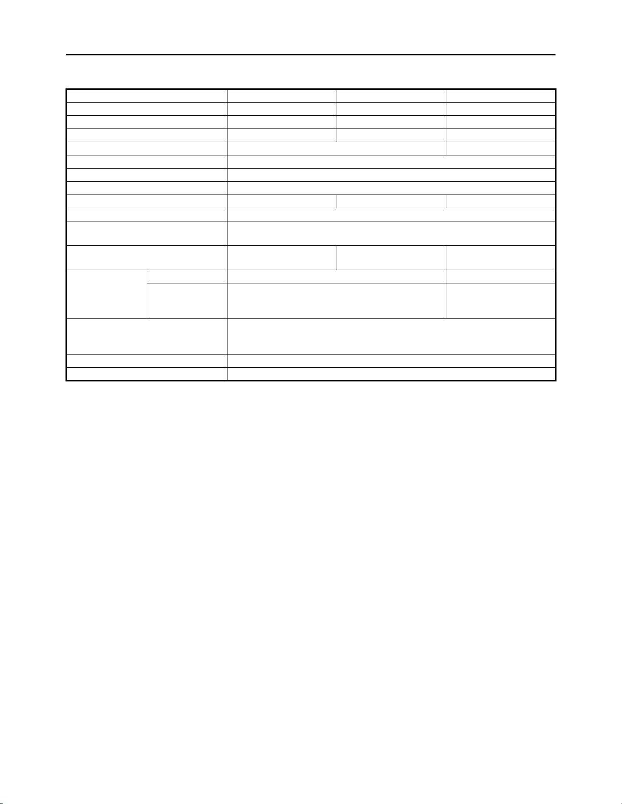
MAJOR SPECIFICATIONS
Model RS90GTZ RS90LTGTZ RST90GTZ
Model code 8JA1 8JB1 8HF3
Catalogue name RS Vector GT RS Vector L-TX GT RS Venture GT
Class Groomed Trail Trail Versatility Touring
Seating Capacity One Two
Engine type Liquid cooled 4-stroke, 12 valves
Cylinder arrangement/Displacement Backward-inclined parallel 3-cylinder/1,049cm
Fuel system type Electronic fuel injection
Track length 3,072 mm (121 in) 3,456 mm (136 in) 3,648 mm (144 in)
Front suspension Independent, double wishbone
Front shock absorber
Rear suspension
Rear shock
absorber
Ski type
Electric start Standard
Reverse Standard
Mono Shock II
RA
Front — 40mm aluminum HPG
Rear
40mm GYTR aluminum HPG
with reservoir dual-clicker
Mono Shock II
RA 136
46mm KYB
aluminum HPG
with remote adjust
Lightweight plastic
saddleless
middle keel
40mm aluminum HPG
with reservoir
compression clicker
3
Pro Comfort
CK 144
IMPORTANT
This manual was produced by the Yamaha Motor Company, Ltd. primarily for use by Yamaha dealers and their qualified mechanics. It is not possible to include all the knowledge of a mechanic in one
manual. Therefore, anyone who uses this book to perform maintenance and repairs on Yamaha
snowmobiles should have a basic understanding of mechanics and the techniques to repair these
types of snowmobiles. Repair and maintenance work attempted by anyone without this knowledge
is likely to render the snowmobile unsafe and unfit for use.
This model has been designed and manufactured to perform within certain specifications in regard
to performance and emissions. Proper service with the correct tools is necessary to ensure that the
snowmobile will operate as designed. If there is any question about a service procedure, it is imperative that you contact a Yamaha dealer for any service information changes that apply to this model.
This policy is intended to provide the customer with the most satisfaction from his snowmobile and
to conform to federal environmental quality objectives.
Yamaha Motor Company, Ltd. is continually striving to improve all of its models. Modifications and
significant changes in specifications or procedures will be forwarded to all authorized Yamaha dealers and will appear in future editions of this manual where applicable.
TIP
• This Service Manual contains information regarding periodic maintenance to the emission control
system. Please read this material carefully.
• Designs and specifications are subject to change without notice.
IMPORTANT MANUAL INFORMATION
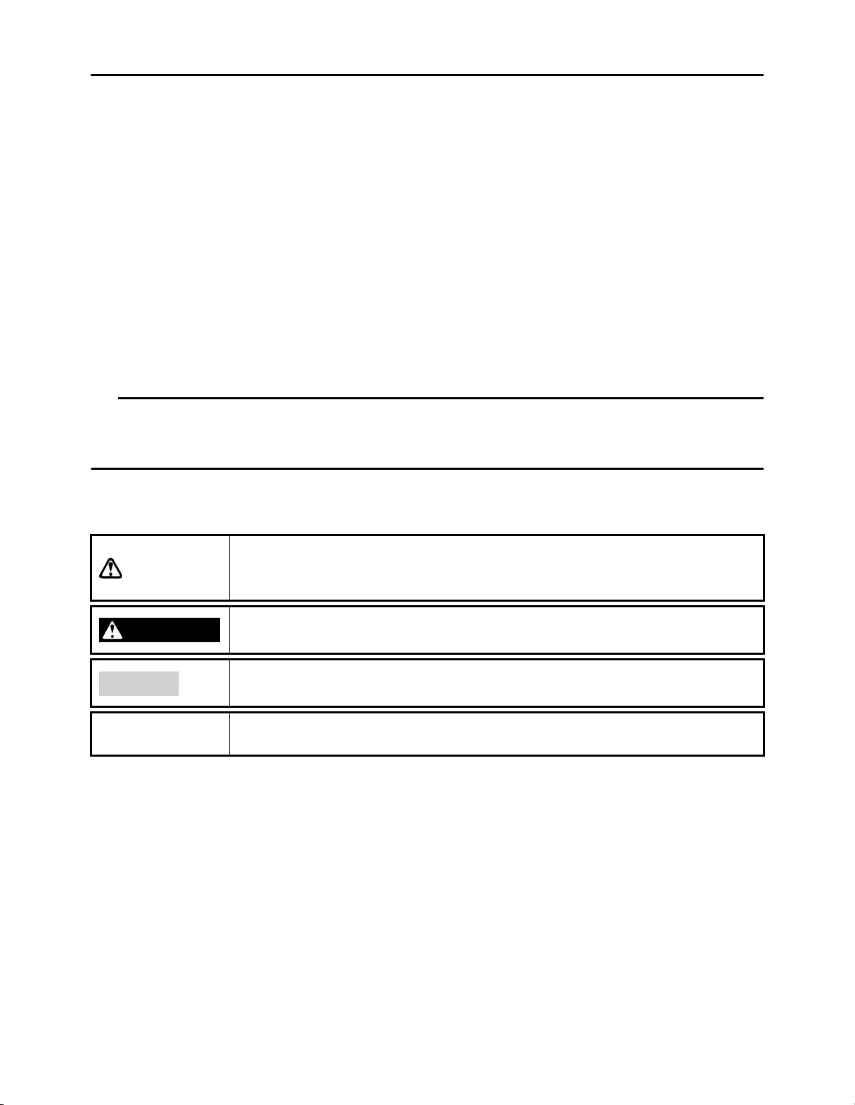
Particularly important information is distinguished in this manual by the following notations.
WARNING
NOTICE
TIP
This is the safety alert symbol. It is used to alert you to potential personal injury hazards. Obey all safety messages that follow this symbol
to avoid possible injury or death.
A WARNING indicates a hazardous situation which, if not avoided,
could result in death or serious injury.
A NOTICE indicates special precautions that must be taken to avoid
damage to the snowmobile or other property.
A TIP provides key information to make procedures easier or clearer.
HOW TO USE THIS MANUAL
This manual is intended as a handy, easy-to-read reference book for the mechanic. Comprehensive
explanations of all installation, removal, disassembly, assembly, repair and check procedures are
laid out with the individual steps in sequential order.
• The manual is divided into chapters. An abbreviation and symbol in the upper right corner of
each page indicate the current chapter.
Refer to “SYMBOLS.”
• Each chapter is divided into sections. The current section title is shown at the top of each page,
except in Chapter 3 (“PERIODIC INSPECTION AND ADJUSTMENT”), where the sub-section
title(s) appears.
• Sub-section titles appear in smaller print than the section title.
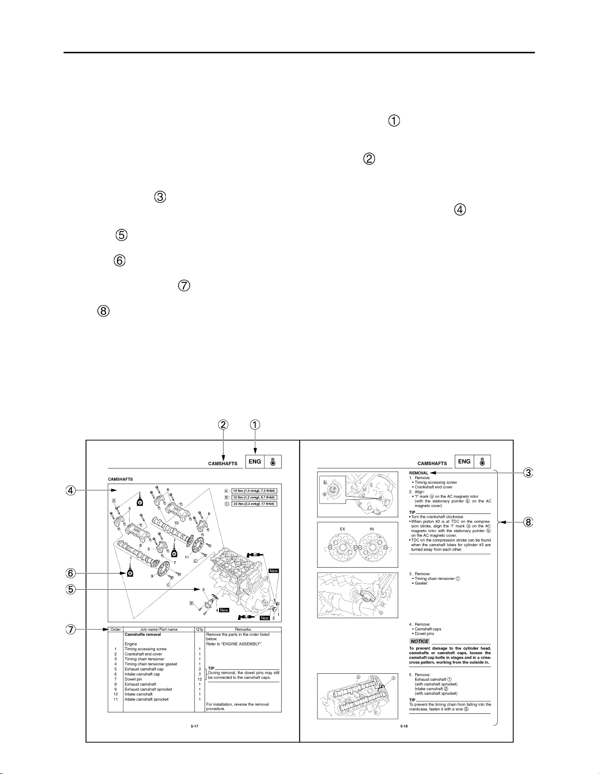
• To help identify parts and clarify procedure steps, there are exploded diagrams at the start of
each removal and disassembly section.
• Numbers are given in the order of the jobs in the exploded diagram. A number indicates a disassembly step.
• Symbols indicate parts to be lubricated or replaced.
Refer to “SYMBOLS”.
• A job instruction chart accompanies the exploded diagram, providing the order of jobs, names
of parts, notes in jobs, etc.
• Jobs requiring more information (such as special tools and technical data) are described
sequentially.
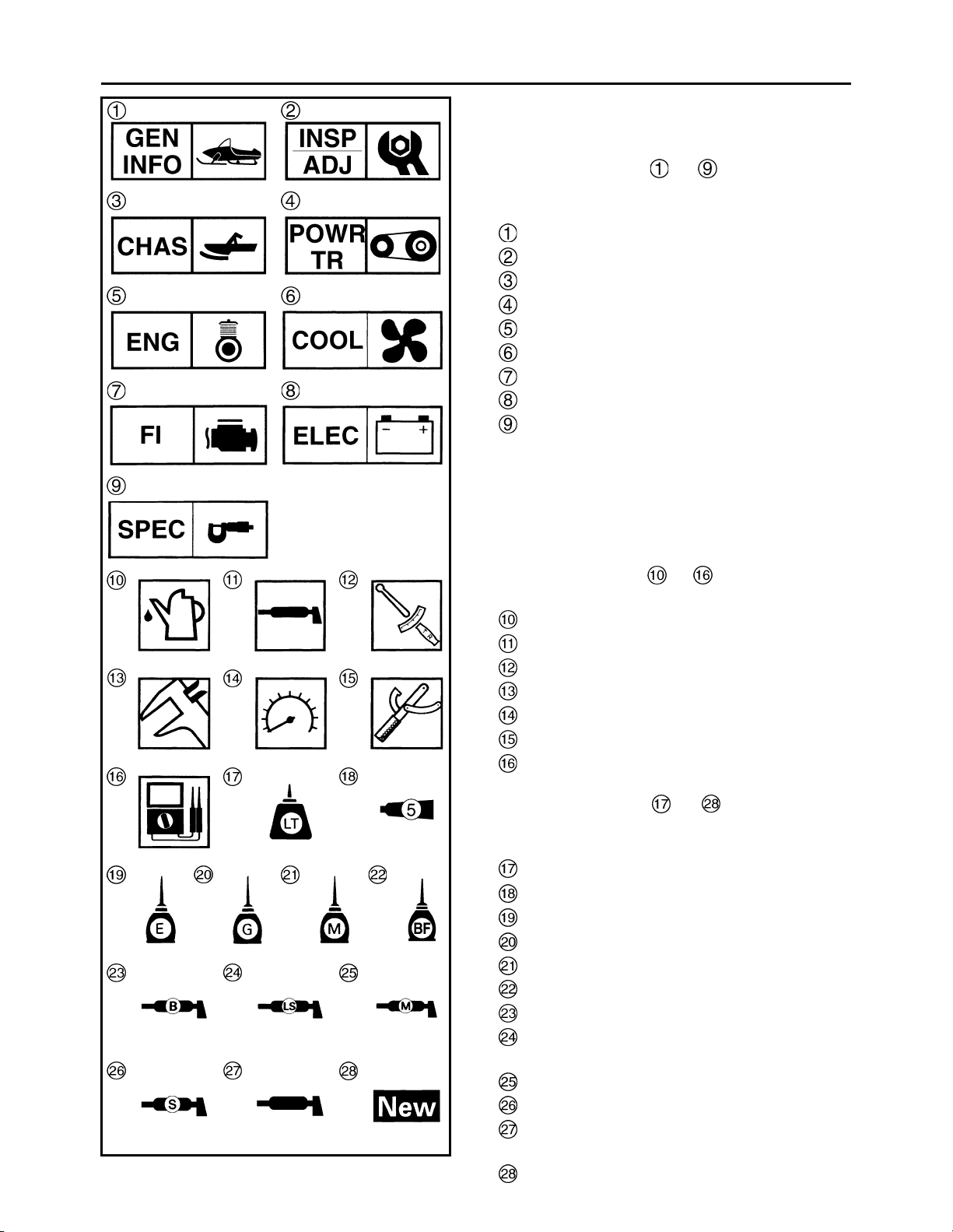
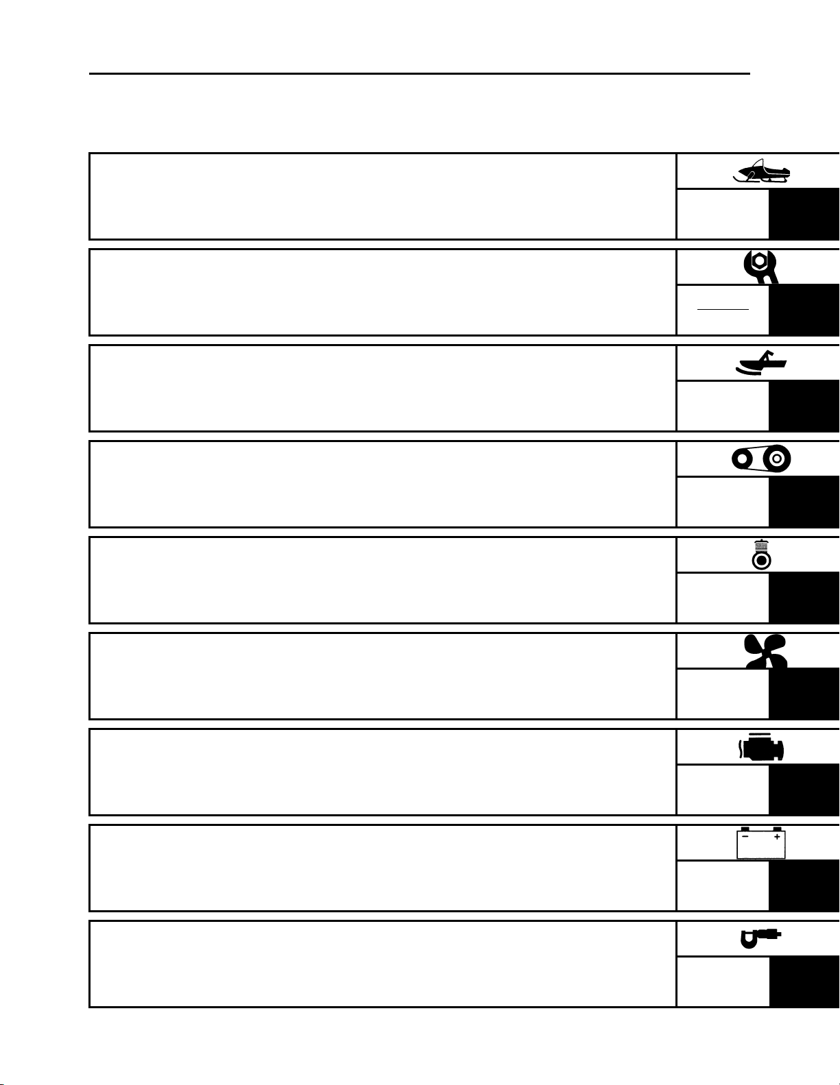
ILLUSTRATED SYMBOLS
(Refer to the illustration)
Illustrated symbols to are designed as
thumb tabs to indicate the chapter’s number
and content.
General information
Periodic inspection and adjustment
Chassis
Power train
Engine
Cooling system
Fuel injection system
Electrical
Specifications
Illustrated symbols to are used to identify the specifications which appear.
Filling fluid
Lubricant
Tightening torque
Wear limit, clearance
Engine speed
Special tool
Electrical data (Ω, V, A)
Illustrated symbols to in the exploded
diagram indicate grade of lubricant and location of lubrication point.
®
Apply locking agent (LOCTITE
Apply Yamabond No. 5
Apply engine oil
Apply gear oil
Apply molybdenum disulfide oil
Apply brake fluid
Apply wheel bearing grease
Apply low-temperature lithium-soap-based
grease
Apply molybdenum disulfide grease
Apply silicone grease
ESSO beacon 325 grease or Aeroshell
grease #7A
Use new one
®
)
CONTENTS
GENERAL INFORMATION
PERIODIC INSPECTION AND
ADJUSTMENT
CHASSIS
POWER TRAIN
ENGINE
GEN
INFO
INSP
ADJ
CHAS
POWR
TR
ENG
1
2
3
4
5
COOLING SYSTEM
FUEL INJECTION SYSTEM
ELECTRICAL
SPECIFICATIONS
COOL
6
FI
7
ELEC
8
SPEC
9

CHAPTER 1.
GENERAL INFORMATION
SNOWMOBILE IDENTIFICATION .............1-1
FRAME SERIAL NUMBER ....................1-1
ENGINE SERIAL NUMBER...................1-1
IMPORTANT INFORMATION ....................1-2
PREPARATION FOR REMOVAL AND
DISASSEMBLY......................................1-2
REPLACEMENT PARTS .......................1-2
GASKETS, OIL SEALS, AND
O-RINGS................................................1-3
LOCK WASHERS/PLATES AND
COTTER PINS.......................................1-3
BEARINGS AND OIL SEALS ................1-3
CIRCLIPS ..............................................1-3
LOCTITE® .............................................1-3
CHECKING THE CONNECTIONS ........1-4
HANDLING THE ELECTRONIC
PARTS ...................................................1-5
SPECIAL TOOLS .......................................1-6
FOR TUNE UP.......................................1-6
FOR ENGINE SERVICE........................1-6
FOR POWER TRAIN SERVICE ............1-9
FOR FUEL INJECTION SERVICE ......1-10
FOR ELECTRICAL SERVICE .............1-10
CHAPTER 2.
PERIODIC INSPECTION AND
ADJUSTMENT
INTRODUCTION.........................................2-1
PERIODIC MAINTENANCE CHART
FOR THE EMISSION CONTROL
SYSTEM .....................................................2-1
GENERAL MAINTENANCE AND
LUBRICATION CHART..............................2-1
ENGINE...................................................... 2-3
SPARK PLUGS ..................................... 2-3
FUEL LINE INSPECTION ..................... 2-4
COOLING SYSTEM .............................. 2-4
VALVE CLEARANCE
ADJUSTMENT .................................... 2-10
THROTTLE BODY
SYNCHRONIZATION.......................... 2-16
THROTTLE CABLE FREE PLAY
ADJUSTMENT .................................... 2-18
THROTTLE OVERRIDE SYSTEM
(T.O.R.S.) CHECK............................... 2-19
COMPRESSION PRESSURE
MEASUREMENT................................. 2-20
ENGINE OIL LEVEL INSPECTION..... 2-22
ENGINE OIL REPLACEMENT............ 2-23
CRANKCASE BREATHER HOSE
INSPECTION....................................... 2-27
CYLINDER HEAD BREATHER
HOSE INSPECTION ........................... 2-27
OIL TANK BREATHER HOSE
INSPECTION....................................... 2-28
THROTTLE BODY JOINTS
INSPECTION....................................... 2-28
CHECKING THE AIR FILTER
ELEMENT............................................ 2-29
EXHAUST SYSTEM INSPECTION..... 2-30
POWER TRAIN ........................................ 2-31
SHEAVE OFFSET ADJUSTMENT...... 2-31
DRIVE V-BELT.................................... 2-33
ENGAGEMENT SPEED CHECK ........ 2-35
PARKING BRAKE PAD
INSPECTION....................................... 2-35
PARKING BRAKE ADJUSTMENT ...... 2-36
BRAKE FLUID LEVEL
INSPECTION....................................... 2-37
BRAKE PAD INSPECTION................. 2-38
BRAKE HOSE INSPECTION .............. 2-38
AIR BLEEDING (HYDRAULIC
BRAKE SYSTEM) ............................... 2-39
DRIVE CHAIN ..................................... 2-40
TRACK TENSION ADJUSTMENT ...... 2-43
SLIDE RUNNER INSPECTION........... 2-45
EXTROVERT SPROCKET WHEELS
(RS90GTZ/RS90LTGTZ) .................... 2-45
MAXIMIZING DRIVE TRACK LIFE ..... 2-46

CHASSIS ..................................................2-47
SKI/SKI RUNNER ...............................2-47
STEERING SYSTEM...........................2-47
BRAKE LEVER ADJUSTMENT...........2-49
LUBRICATION.....................................2-49
ELECTRICAL ...........................................2-52
HEADLIGHT BULB
REPLACEMENT ..................................2-52
HEADLIGHT BEAM
ADJUSTMENT.....................................2-53
BATTERY INSPECTION .....................2-54
FUSE INSPECTION ............................2-61
SKI............................................................ 3-20
SKI....................................................... 3-20
INSPECTION....................................... 3-21
FRONT SUSPENSION............................. 3-22
HANDLING THE FRONT SHOCK
ABSORBER AND GAS
CYLINDER .......................................... 3-24
DISPOSING OF A FRONT SHOCK
ABSORBER AND GAS
CYLINDER .......................................... 3-24
INSPECTION....................................... 3-24
INSTALLATION................................... 3-25
TUNING ....................................................2-63
CLUTCH ..............................................2-63
GEAR SELECTION .............................2-74
HIGH ALTITUDE TUNING...................2-75
FRONT SUSPENSION ........................2-78
REAR SUSPENSION ..........................2-81
TROUBLESHOOTING (SKI,
SUSPENSION) ....................................2-89
CHAPTER 3.
CHASSIS
COWLINGS ................................................3-1
SHROUD AND COVERS.......................3-1
WINDSHIELD AND HEADLIGHT
(RS90GTZ/RS90LTGTZ) ......................3-2
WINDSHIELD AND HEADLIGHT
(RST90GTZ) ..........................................3-3
AIR FILTER CASE.................................3-4
SEAT...........................................................3-5
SEAT (RS90GTZ/RS90LTGTZ) ............3-5
BACKREST AND SEAT.............................3-6
BACKREST AND SEAT
(RST90GTZ) ..........................................3-6
STORAGE COMPARTMENT
(RST90GTZ) ..........................................3-7
STEERING..................................................3-8
STEERING (RS90GTZ/
RS90LTGTZ) .........................................3-8
STEERING (RST90GTZ).....................3-10
REMOVAL ...........................................3-14
INSPECTION .......................................3-14
INSTALLATION ...................................3-15
CHAPTER 4.
POWER TRAIN
PRIMARY SHEAVE AND DRIVE
V-BELT....................................................... 4-1
REMOVAL............................................. 4-4
DISASSEMBLY ..................................... 4-4
INSPECTION......................................... 4-5
ASSEMBLY ........................................... 4-8
INSTALLATION................................... 4-11
SECONDARY SHEAVE........................... 4-13
DISASSEMBLY ................................... 4-15
INSPECTION....................................... 4-15
ASSEMBLY ......................................... 4-16
INSTALLATION................................... 4-18
DRIVE CHAIN HOUSING ........................ 4-20
DRIVE CHAIN HOUSING
(RS90GTZ/RS90LTGTZ) .................... 4-20
DRIVE CHAIN HOUSING
(RST90GTZ)........................................ 4-23
REMOVAL........................................... 4-26
INSPECTION....................................... 4-26
INSTALLATION (RS90GTZ/
RS90LTGTZ)....................................... 4-29
INSTALLATION (RST90GTZ) ............ 4-30
SECONDARY SHAFT.............................. 4-32
REMOVAL........................................... 4-33
INSPECTION....................................... 4-33
INSTALLATION................................... 4-34
SECONDARY SHAFT AND DRIVE
CHAIN HOUSING INSTALLATION..... 4-35

BRAKE .....................................................4-37
BRAKE (RS90GTZ/RS90LTGTZ) .......4-37
BRAKE (RST90GTZ) ...........................4-38
BRAKE PAD REPLACEMENT ............4-39
BRAKE CALIPER AND PARKING
BRAKE (RS90GTZ/RS90LTGTZ) .......4-42
BRAKE CALIPER AND PARKING
BRAKE (RST90GTZ) ...........................4-44
BRAKE CALIPER DISASSEMBLY ......4-46
BRAKE CALIPER INSPECTION
AND REPAIR .......................................4-47
BRAKE CALIPER ASSEMBLY ............4-48
BRAKE CALIPER INSTALLATION......4-49
BRAKE MASTER CYLINDER
(RS90GTZ/RS90LTGTZ) ....................4-50
BRAKE MASTER CYLINDER
(RST90GTZ) ........................................4-52
INSPECTION .......................................4-54
BRAKE MASTER CYLINDER
ASSEMBLY..........................................4-54
INSTALLATION ...................................4-55
EXHAUST PIPE AND MUFFLER .............. 5-5
INSTALLATION..................................... 5-7
OIL TANK................................................... 5-9
ENGINE ASSEMBLY............................... 5-10
LEADS AND HOSES........................... 5-10
ENGINE ASSEMBLY .......................... 5-13
REMOVAL........................................... 5-15
INSTALLATION................................... 5-15
CAMSHAFTS ........................................... 5-17
CYLINDER HEAD COVER.................. 5-17
CAMSHAFTS ...................................... 5-18
REMOVAL........................................... 5-19
INSPECTION....................................... 5-20
INSTALLATION................................... 5-24
CYLINDER HEAD .................................... 5-28
REMOVAL........................................... 5-29
INSPECTION....................................... 5-29
INSTALLATION................................... 5-30
SLIDE RAIL SUSPENSION......................4-56
SLIDE RAIL SUSPENSION
(RS90GTZ) ..........................................4-56
SLIDE RAIL SUSPENSION
(RS90LTGTZ) ......................................4-62
SLIDE RAIL SUSPENSION
(RST90GTZ) ........................................4-68
REMOVAL ...........................................4-75
HANDLING THE REAR SHOCK
ABSORBER AND GAS CYLINDER.....4-75
DISPOSING OF A REAR SHOCK
ABSORBER AND GAS CYLINDER.....4-76
INSPECTION .......................................4-77
ASSEMBLY..........................................4-78
INSTALLATION ...................................4-79
TROUBLESHOOTING.........................4-79
FRONT AXLE AND TRACK.....................4-82
INSPECTION .......................................4-83
INSTALLATION ...................................4-83
VALVES AND VALVE SPRINGS ............ 5-32
REMOVAL........................................... 5-33
INSPECTION....................................... 5-34
INSTALLATION................................... 5-40
AC MAGNETO ROTOR AND STARTER
CLUTCH................................................... 5-43
REMOVAL........................................... 5-44
INSPECTION....................................... 5-45
INSTALLATION................................... 5-46
OIL PAN AND OIL PUMP........................ 5-48
REMOVAL........................................... 5-51
INSPECTION....................................... 5-51
INSTALLATION................................... 5-53
CRANKCASE........................................... 5-56
REMOVAL........................................... 5-58
INSPECTION....................................... 5-59
INSTALLATION................................... 5-60
CHAPTER 5.
ENGINE
FUEL TANK................................................5-1
REMOVAL .............................................5-2
INSPECTION .........................................5-2
INSTALLATION .....................................5-3
CONNECTING RODS AND PISTONS .... 5-65
REMOVAL........................................... 5-66
INSPECTION....................................... 5-67
INSTALLATION................................... 5-73

CRANKSHAFT AND BALANCER
SHAFT ......................................................5-77
REMOVE .............................................5-79
INSPECTION .......................................5-80
INSTALLATION ...................................5-84
CHAPTER 6.
COOLING SYSTEM
HEAT EXCHANGER ..................................6-1
HEAT EXCHANGER (RS90GTZ/
RS90LTGTZ) .........................................6-1
HEAT EXCHANGER (RST90GTZ)........6-4
INSPECTION .........................................6-6
INSTALLATION .....................................6-7
THERMOSTAT ...........................................6-8
IINSPECTION ........................................6-9
INSTALLATION .....................................6-9
WATER PUMP..........................................6-11
REMOVAL ...........................................6-13
DISASSEMBLY....................................6-13
INSPECTION .......................................6-14
ASSEMBLY..........................................6-14
INSTALLATION ...................................6-16
CHAPTER 7.
FUEL INJECTION SYSTEM
FUEL INJECTION SYSTEM.......................7-1
CIRCUIT DIAGRAM (RS90GTZ/
RS90LTGTZ) .........................................7-3
CIRCUIT DIAGRAM (RST90GTZ).........7-5
ECU SELF-DIAGNOSTIC
FUNCTION ............................................7-7
SELF-DIAGNOSTIC FUNCTION
TABLE....................................................7-7
TROUBLESHOOTING CHART .............7-9
DIAGNOSTIC MODE...........................7-10
TROUBLESHOOTING DETAILS.........7-18
OIL PRESSURE SWITCH ...................7-31
INTAKE AIR TEMPERATURE
SENSOR..............................................7-31
ISC (IDLE SPEED CONTROL)
UNIT.....................................................7-32
THROTTLE BODY ................................... 7-33
INJECTORS ........................................ 7-35
REMOVAL........................................... 7-36
INSPECTION....................................... 7-36
FUEL PRESSURE INSPECTION........ 7-37
INSPECTION AND ADJUSTMENT..... 7-38
CHAPTER 8.
ELECTRICAL
SWITCH INSPECTION .............................. 8-1
SWITCH INSPECTION ......................... 8-1
INSPECTING A SWITCH SHOWN
IN THE MANUAL................................... 8-1
IGNITION SYSTEM.................................... 8-2
CIRCUIT DIAGRAM (RS90GTZ/
RS90LTGTZ)......................................... 8-2
CIRCUIT DIAGRAM (RST90GTZ) ........ 8-4
TROUBLESHOOTING .......................... 8-6
IGNITION SPARK GAP......................... 8-8
IGNITION COIL ..................................... 8-8
CRANKSHAFT POSITION SENSOR.... 8-9
THROTTLE OVERRIDE SYSTEM
(T.O.R.S.) ............................................ 8-10
ENGINE STOP SWITCH..................... 8-11
THROTTLE SWITCH .......................... 8-12
MAIN SWITCH .................................... 8-12
ELECTRICAL STARTING SYSTEM........ 8-13
CIRCUIT DIAGRAM (RS90GTZ/
RS90LTGTZ)....................................... 8-13
CIRCUIT DIAGRAM (RST90GTZ) ...... 8-14
TROUBLESHOOTING ........................ 8-15
STARTER MOTOR ............................. 8-17
CHARGING SYSTEM .............................. 8-22
CIRCUIT DIAGRAM (RS90GTZ/
RS90LTGTZ)....................................... 8-22
CIRCUIT DIAGRAM (RST90GTZ) ...... 8-23
TROUBLESHOOTING ........................ 8-24
BATTERY............................................ 8-26
STATOR COIL..................................... 8-26

LIGHTING SYSTEM .................................8-28
CIRCUIT DIAGRAM (RS90GTZ/
RS90LTGTZ) .......................................8-28
CIRCUIT DIAGRAM (RST90GTZ).......8-30
TROUBLESHOOTING.........................8-32
BULB(S)...............................................8-35
HEADLIGHT BEAM SWITCH ..............8-35
HEADLIGHT RELAY............................8-36
LOAD CONTROL RELAY....................8-37
SIGNAL SYSTEM.....................................8-38
CIRCUIT DIAGRAM (RS90GTZ/
RS90LTGTZ) .......................................8-38
CIRCUIT DIAGRAM (RST90GTZ).......8-40
TROUBLESHOOTING.........................8-42
BRAKE LIGHT SWITCH ......................8-48
GEAR POSITION SWITCH .................8-48
DC BACK BUZZER..............................8-49
COOLANT TEMPERATURE
SENSOR..............................................8-49
OIL LEVEL SWITCH............................8-50
FUEL SENDER....................................8-51
SPEED SENSOR.................................8-52
CHAPTER 9.
SPECIFICATIONS
GENERAL SPECIFICATIONS................... 9-1
MAINTENANCE SPECIFICATIONS .......... 9-4
ENGINE................................................. 9-4
POWER TRAIN ..................................... 9-9
CHASSIS............................................. 9-13
ELECTRICAL ...................................... 9-14
GENERAL TORQUE
SPECIFICATIONS ................................... 9-16
DEFINITION OF UNITS ........................... 9-16
TIGHTENING TORQUE ........................... 9-17
ENGINE............................................... 9-17
POWER TRAIN ................................... 9-20
CHASSIS............................................. 9-23
CABLE ROUTING.................................... 9-25
GRIP WARMER SYSTEM ........................8-54
CIRCUIT DIAGRAM (RS90GTZ/
RS90LTGTZ) .......................................8-54
CIRCUIT DIAGRAM (RST90GTZ).......8-56
TROUBLESHOOTING.........................8-58
GRIP/THUMB WARMER
ADJUSTMENT SWITCH......................8-59
GRIP WARMER AND THUMB
WARMER.............................................8-61
GRIP/THUMB WARMER
ADJUSTMENT SWITCH......................8-61
PASSENGER GRIP WARMER
(RST90GTZ) ........................................8-62
PASSENGER GRIP WARMER
SWITCH (RST90GTZ) .........................8-62
PASSENGER GRIP WARMER
RELAY (RST90GTZ) ...........................8-63
COOLING SYSTEM..................................8-64
CIRCUIT DIAGRAM (RS90GTZ/
RS90LTGTZ) .......................................8-64
TROUBLESHOOTING.........................8-66
RADIATOR FAN MOTOR
(RS90GTZ/RS90LTGTZ) ....................8-67
RADIATOR FAN MOTOR RELAY
(RS90GTZ/RS90LTGTZ) ....................8-67
GEN
SNOWMOBILE IDENTIFICATION
INFO
GENERAL INFORMATION
SNOWMOBILE IDENTIFICATION
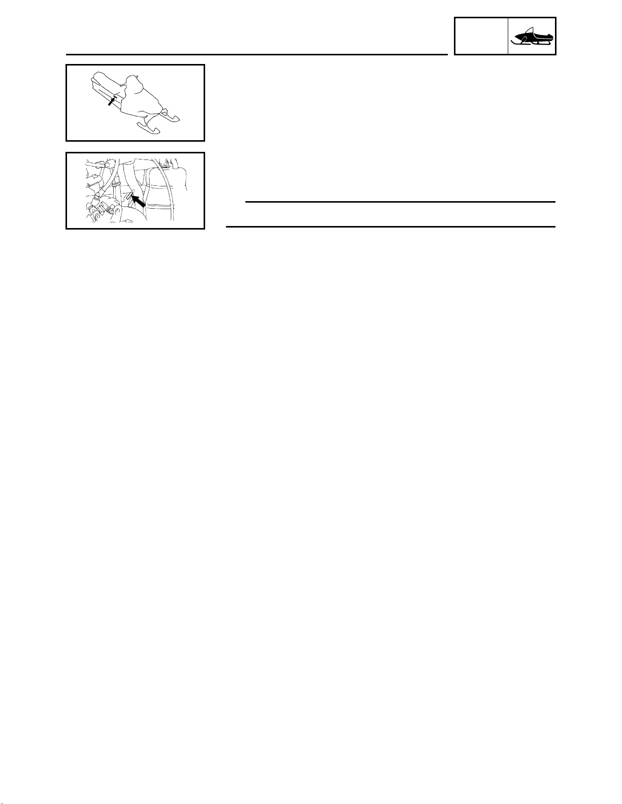
FRAME SERIAL NUMBER
The frame serial number is located on the right-hand side of the
frame (just below the front of the seat).
ENGINE SERIAL NUMBER
The engine serial number is located on the right-hand side of the
crankcase.
TIP
Designs and specifications are subject to change without notice.
1-1
GEN
IMPORTANT INFORMATION
IMPORTANT INFORMATION
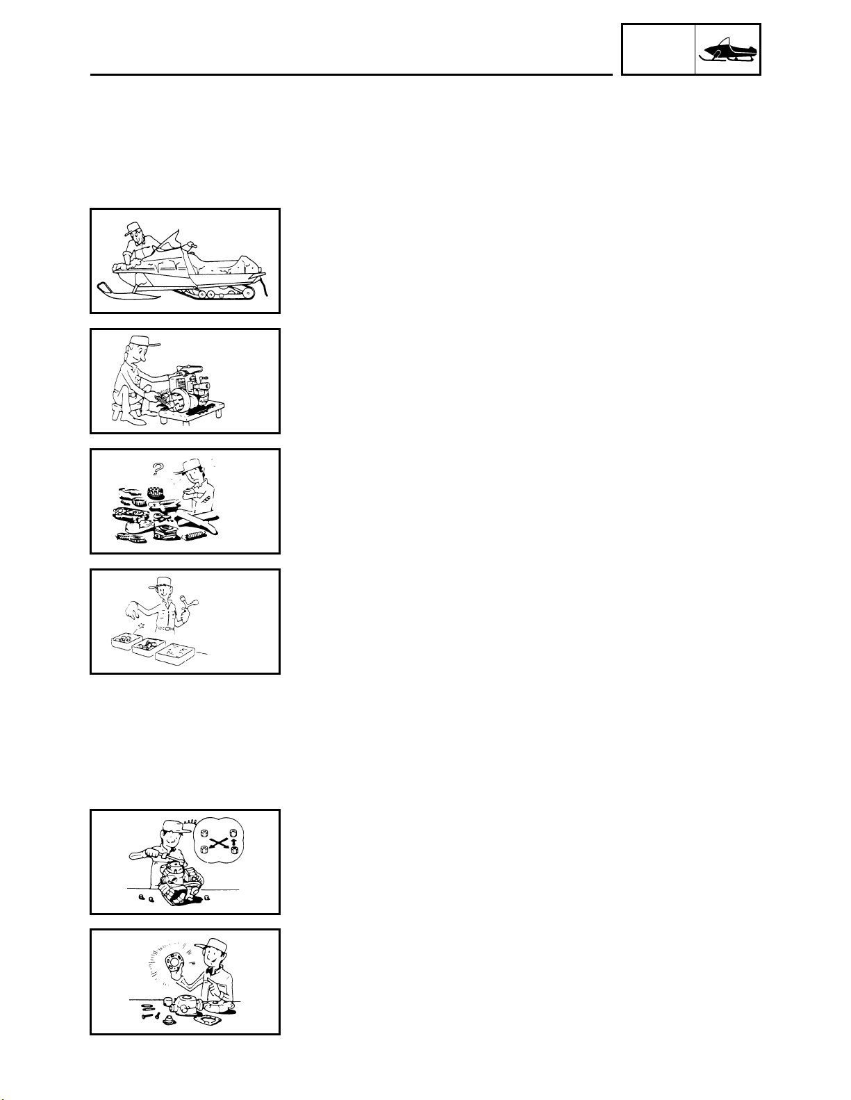
PREPARATION FOR REMOVAL AND DISASSEMBLY
1. Remove all dirt, mud, dust, and foreign material before removal
and disassembly.
While cleaning, take care to protect the electrical parts, such as
relays, switches, motor, resistors, controllers, etc., from high
pressure water splashes.
2. Use proper tools and cleaning equipment.
Refer to “SPECIAL TOOLS”.
INFO
3. When disassembling the snowmobile, keep mated parts
together. This includes gears, cylinders, pistons, and other parts
that have been “mated” through normal wear. Mated parts must
be reused or replaced as an assembly.
4. During disassembly of the snowmobile, clean all parts and
place them in trays in the order of disassembly. This will speed
up assembly time and help ensure that all parts are reinstalled
correctly.
5. Keep all parts away from any source of fire.
6. Be sure to keep to the tightening torque specifications. When
tightening bolts, nuts, and screws, start with those that have
larger diameters, and proceed from the inside to the outside in a
crisscross pattern.
REPLACEMENT PARTS
Use only genuine Yamaha parts for all replacements. Use oil and
grease recommended by Yamaha for all lubrication jobs. Other
brands may be similar in function and appearance, but inferior in
quality.
1-2
GEN
IMPORTANT INFORMATION
GASKETS, OIL SEALS, AND O-RINGS
1. All gaskets, seals, and O-rings should be replaced when an
engine is overhauled. All gasket surfaces, oil seal lips, and Orings must be cleaned.
2. Properly oil all mating parts and bearings during reassembly.
Apply grease to the oil seal lips.
LOCK WASHERS/PLATES AND COTTER PINS
All lock washers/ plates and cotter pins must be replaced if they
are removed. Lock tab(s) should be bent along the bolt or nut flat(s)
after the bolt or nut has been properly tightened.
INFO
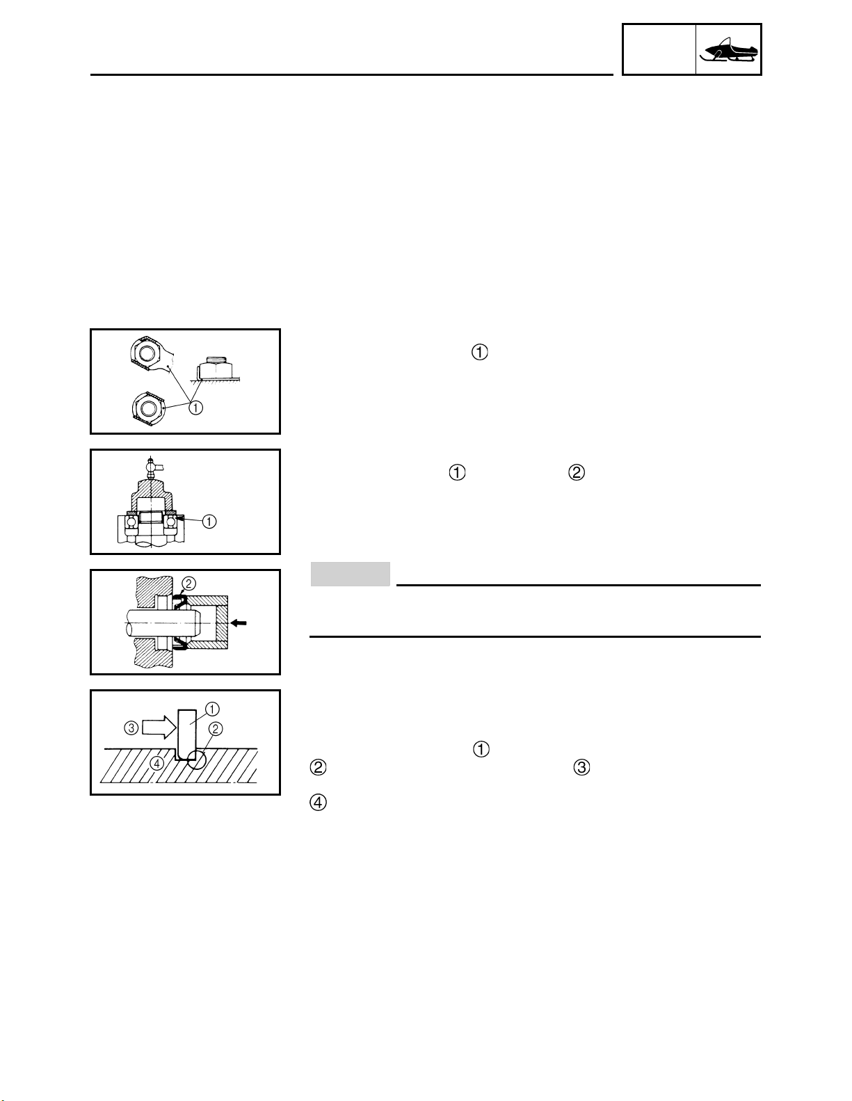
BEARINGS AND OIL SEALS
Install the bearings and oil seals with their manufacturer’s
marks or numbers facing outwards. (In other words, the stamped
letters must be on the side exposed to view.) When installing oil
seals, apply a light coating of lightweight lithium base grease to the
seal lips. Oil the bearings liberally when installing.
NOTICE
Do not use compressed air to spin the bearings dry. This
causes damage to the surface of the bearings.
CIRCLIPS
All circlips should be inspected carefully before reassembly. Always
replace piston pin clips after one use. Replace misshapen circlips.
When installing a circlip , make sure that the sharp edged corner
is positioned opposite to the thrust it receives. See the sec-
tional view.
Shaft
LOCTITE
After installing fasteners that have LOCTITE® applied, wait 24
hours before using the snowmobile. This will give the LOCTITE
time to dry properly.
®
1-3
®
GEN
IMPORTANT INFORMATION
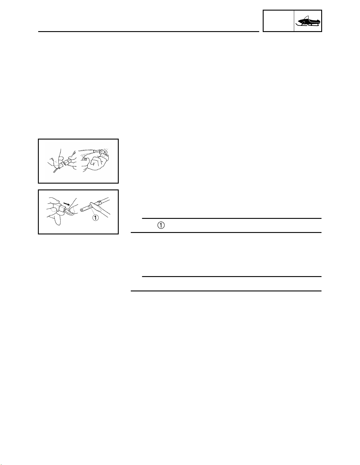
CHECKING THE CONNECTIONS
Check the leads, couplers, and connectors for stains, rust, moisture, etc.
1. Disconnect:
• Lead
• Coupler
• Connector
2. Inspect:
• Lead
• Coupler
• Connector
Moisture → Dry with an air blower.
Rust/stains → Connect and disconnect several times.
INFO
3. Inspect:
• All connections
Loose connection → Connect properly.
TIP
If the pin on the terminal is flattened, bend it up.
4. Connect:
• Lead
• Coupler
• Connector
TIP
Make sure all connections are tight.
1-4
GEN
IMPORTANT INFORMATION
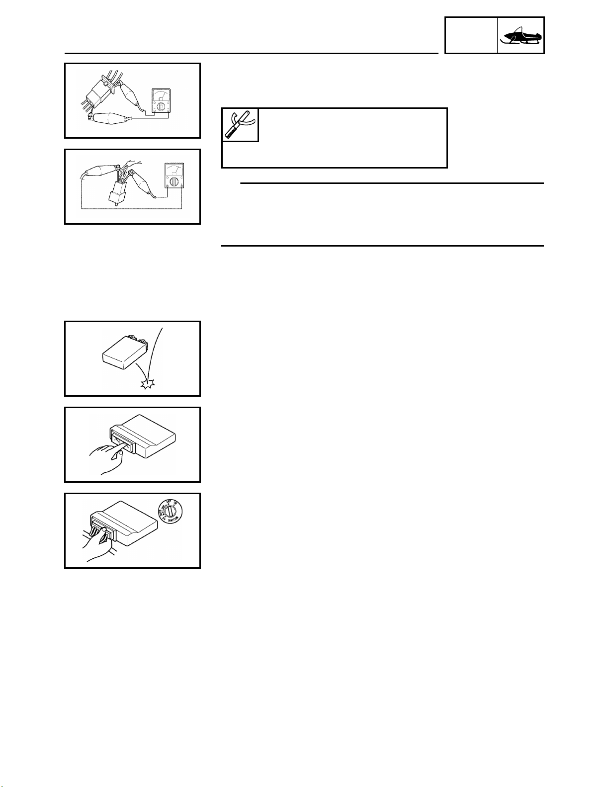
5. Inspect:
•Continuity
(with the analog pocket tester (pocket tester))
Analog pocket tester
YU-03112-C
Pocket tester
90890-03112
TIP
• If there is no continuity, clean the terminals.
• When checking the wire harness, perform steps (1) to (3).
• As a quick remedy, use a contact revitalizer available at most part
stores.
INFO
HANDLING THE ELECTRONIC PARTS
Electronic parts is very sensitive.
Handle with care and do not give impact.
Mankind has static electricity and it’s voltage is very high and electronic parts is very sensitive.
It has possibility that inside small parts of electronic parts is
destroyed by static electricity.
Do not touch and do not make it dirty.
When you disconnect electronic parts from wire harness, always
turn off main switch.
If you disconnect above condition, it may gives damages to electronic parts.
1-5
GEN
SPECIAL TOOLS
SPECIAL TOOLS
Some special tools are necessary for a completely accurate tuneup and assembly. Using the correct special tool will help prevent
damage that can be caused by the use of improper tools or improvised techniques.
TIP
• Be sure to use the correct part number when ordering the tool,
since the part number may differ according to country.
• For USA and Canada, use part number starting with “YB-”, “YM-”,
“YU-” or “YS-”.
• For others, use part number starting with “90890-”.
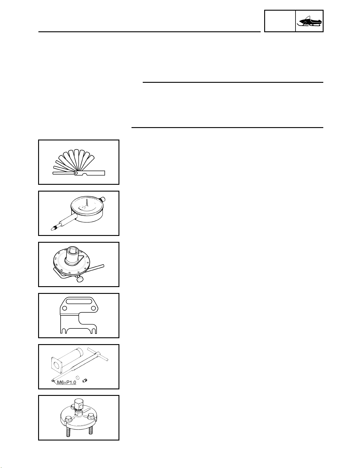
FOR TUNE UP
• Feeler gauge set
P/N: YU-26900-9
• Thickness gauge
P/N: 90890-03180
This gauge is used for clearance measurements.
INFO
• Dial indicator gauge
P/N: YU-A8428
• Dial gauge
P/N: 90890-03097
This gauge is used for runout measurements.
• Angle gauge
Use goods on the market.
This gauge is used to tighten to specified angles.
• Steering linkage alignment plate
P/N: YS-01487
• Steering link holder
P/N: 90890-01487
Locks steering relay arms in place while adjusting the steering linkage for front-end alignment.
FOR ENGINE SERVICE
• Piston pin puller
P/N: YU-01304
• Piston pin puller set
P/N: 90890-01304
This tool is used to remove the piston pin.
• Heavy duty puller
P/N: YU-33270-B
• Flywheel puller
P/N: 90890-01362
This tool is used to remove the magneto rotor.
1-6
SPECIAL TOOLS
• Crankshaft protector
P/N: YM-33282
• Flywheel puller attachment
P/N: 90890-04089
This tool is used to remove the magneto rotor.
• Radiator pressure tester
P/N: YU-24460-01
• Radiator cap tester
P/N: 90890-01325
This tester is used to check the cooling system.
• Radiator pressure tester adapter
P/N: YU-33984
• Radiator cap tester adapter
P/N: 90890-01352
This adapter is used to check the cooling system.
GEN
INFO
• Oil filter wrench
P/N: YM-01469
90890-01469
This tool is needed to loosen or tighten the oil filter cartridge.
• Carburetor synchronizer
P/N: YU-44456
• Vacuum gauge
P/N: 90890-03094
This tool is used to synchronize the throttle bodies.
• Engine compression tester
P/N: YU-33223
• Compression gauge
P/N: 90890-03081
This tool is used to measure engine compression.
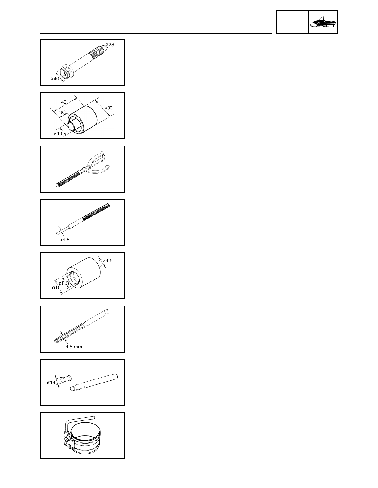
• Valve spring compressor
P/N: YM-04019
90890-04019
This tool is used to remove or install the valve assemblies.
• Valve spring compressor adapter 19.5 mm
P/N: YM-04114
• Valve spring compressor attachment
P/N: 90890-04114
This tool is used to remove or install the valve assemblies.
1-7
GEN
SPECIAL TOOLS
• Bearing driver 40 mm
P/N: YM-04058
• Middle driven shaft bearing driver
P/N: 90890-04058
This tool is used to install the water pump seal.
• Mechanical seal installer 30 – 10 mm
P/N: 90890-01557
This tool is used to install the water pump seal.
• Universal magneto & rotor holder
P/N: YU-01235
• Rotor holding tool
P/N: 90890-01235
This tool is used to hold the camshaft sprockets and oil pump
driven gear.
INFO
• Valve guide remover (4.5 mm)
P/N: YM-04116
• Valve guide remover (ø4.5)
P/N: 90890-04116
This tool is used to remove or install the valve guides.
• Valve guide installer (4.5 mm)
P/N: YM-04117
• Valve guide installer (ø4.5)
P/N: 90890-04117
This tool is used to install the valve guides.
• Valve guide reamer (4.5 mm)
P/N: YM-04118
• Valve guide reamer (ø4.5)
P/N: 90890-04118
This tool is used to rebore the new valve guides.
• Valve lapping tool
P/N: YM-A8998
• Valve lapper
P/N: 90890-04101
This tool is needed to remove and install the valve lifters.
• Piston ring compressor
P/N: YM-08037
90890-05158
This tool is used to compress the piston rings when installing the
piston into the cylinder.
1-8
GEN
SPECIAL TOOLS
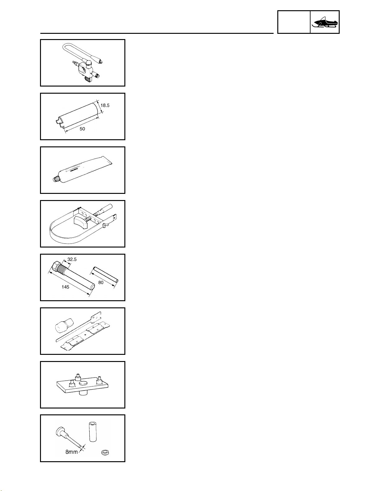
• Oppama pet-4000 spark checker
P/N: YM-34487
• Ignition checker
P/N: 90890-06754
This tool is used to check the ignition system component.
• Engine mount spacer wrench
P/N: YS-01516
• Engine adjuster
P/N: 90890-01516
Used to turn the engine mounting bolt spacer when removing/
installing engine.
• Yamaha bond No. 1215
P/N: 90890-85505
(Three Bond No.1215
This bond is used to seal two mating surfaces (e.g., crankcase mating surfaces.)
®
)
INFO
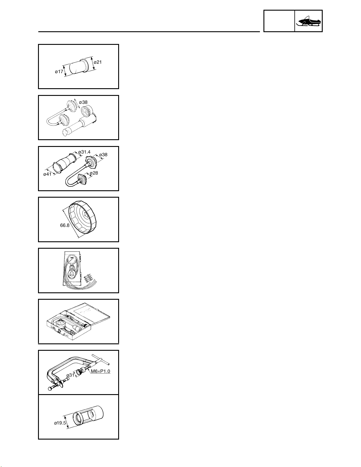
FOR POWER TRAIN SERVICE
• Primary clutch holder
P/N: YS-01880-A
• Sheave holder
P/N: 90890-01701
This tool is used to hold the primary sheave and AC magneto rotor.
• Primary clutch puller
P/N: YS-01881-A
• Primary fixed sheave puller (M18 – 32.5 mm)
P/N: 90890-01556
This tool is used for removing the primary sheave.
• Clutch spider separator
P/N: YS-28890-C
• Clutch separator wrench
P/N: 90890-01740
This tool is used when disassembling and assembling the primary
sheave.
• Clutch separator adapter
P/N: YS-34480
90890-01711
This tool is used when disassembling and assembling the primary
sheave.
• 8 mm clutch bushing jig
P/N: YS-39752
• Clutch bushing jig kit
P/N: 90890-01528
This tool is used for removal and installation of primary clutch
weight and roller bushings.
1-9
GEN
SPECIAL TOOLS
• Primary/Secondary bushing jig
P/N: YS-42424
• Clutch bushing press
P/N: 90890-01529
This tool is used for removing and installing the post bushings (primary sheave cap bush, sliding sheave bush and torque cam bush).
• Track clip installer
P/N: YS-91045-C
90890-01533
This tool is used for installing the track clip.
FOR FUEL INJECTION SERVICE
• Fuel pressure adapter
P/N: YM-03176
90890-03176
This tool is needed to measure fuel pressure.
INFO
• Pressure gauge
P/N: YU-03153
90890-03153
This tool is used to measure fuel pressure.
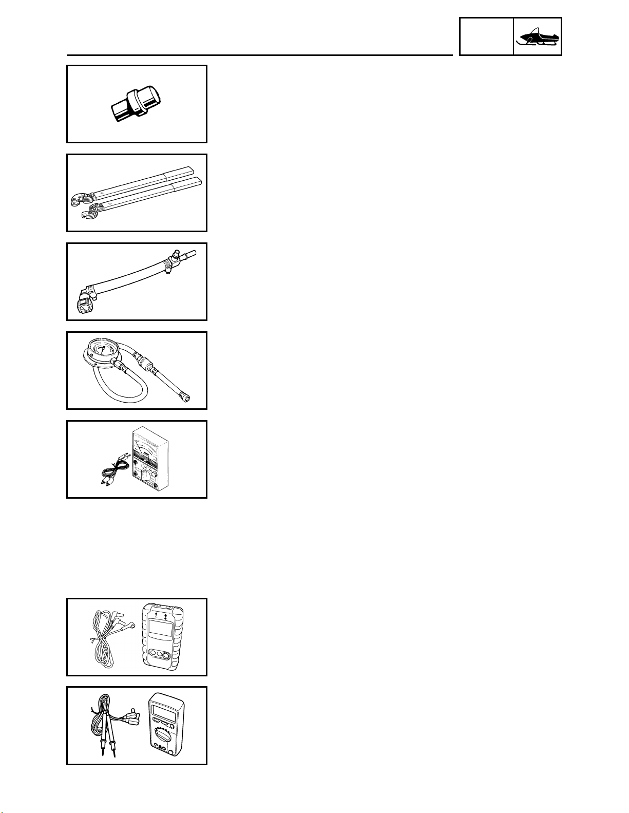
FOR ELECTRICAL SERVICE
• Analog pocket tester
P/N: YU-03112-C
• Pocket tester
P/N: 90890-03112
This instrument is necessary for checking the electrical components.
• Digital tachometer
Use goods on the market.
Recommended goods: kaise SK-8401
This tool is used to check engine speed.
• Model 88 Multimeter with tachometer
P/N: YU-A1927
• Digital circuit tester
P/N: 90890-03174
This instrument is necessary for checking the electrical components.
1-10
GEN
SPECIAL TOOLS
• Test harness S- pressure sensor (3P)
P/N: 90890-03207
This tool is used to measure voltage of the pressure sensor.
• Test harness- TPS (3P)
P/N: 90890-03204
This tool is used to measure voltage of the throttle position sensor.
• Test harness- speed sensor (3P)
P/N: YU-03208
90890-03208
This tool is used to measure voltage of the speed sensor.
INFO
1-11
INTRODUCTION/ PERIODIC MAINTENANCE
CHART FOR THE EMISSION CONTROL SYSTEM/
GENERAL MAINTENANCE AND LUBRICATION CHART
INSP
ADJ
PERIODIC INSPECTION AND ADJUSTMENT
INTRODUCTION
This chapter includes all information necessary to perform recommended inspections and adjustments. These preventive maintenance procedures, if followed, will ensure more reliable snowmobile
operation and a longer service life. In addition, the need for costly overhaul work will be greatly
reduced. This information applies to snowmobiles already in service as well as new snowmobiles
that are being prepared for sale. All service technicians should be familiar with this entire chapter.
PERIODIC MAINTENANCE CHART FOR THE EMISSION CONTROL SYSTEM
Items marked with an asterisk should be performed by a Yamaha dealer as they require special
tools, data and technical skills.
INITIAL EVERY
ITEM REMARKS
• Check condition.
Spark plugs
* Valve clearance • Check and adjust valve clearance when engine is cold. Every 40,000 km (25,000 mi)
* Crankcase breather system
* Fuel line
* Fuel injection
* Exhaust system
• Adjust gap and clean.
• Replace if necessary.
• Check breather hose for cracks or damage.
• Replace if necessary.
• Check fuel hose for cracks or damage.
• Replace if necessary.
• Check synchronization.
• Adjust if necessary.
• Check for leakage.
• Tighten or replace gasket if necessary.
1 month
or 800 km
(500 mi)
(40 hr)
Seasonally
or 4,000 km
(2,500 mi)
(200 hr)
GENERAL MAINTENANCE AND LUBRICATION CHART
ITEM REMARKS
Engine oil • Change (warm engine before draining).
* Engine oil filter cartridge • Replace.
* Cooling system
Primary and secondary
*
clutches
* Drive chain
• Check coolant level.
• Air bleed the cooling system if necessary.
• Check engagement and shift speed.
• Adjust if necessary.
• Inspect sheaves for wear and damage.
• Inspect weights/rollers and bushings for wear for primary.
• Inspect ramp shoes/bushings for wear for secondary.
• Replace if necessary.
• Lubricate with specified grease.
• Check chain slack.
• Adjust if necessary.
INITIAL EVERY
1 month
or 800 km
(500 mi)
(40 hr)
Whenever operating eleva-
tion is changed.
Initial at 500 km (300 mi) and
every 800 km (500 mi)
Seasonally
or 4,000 km
(2,500 mi)
(200 hr)
Every
20,000 km
(12,000 mi)
thereafter.
2-1
GENERAL MAINTENANCE AND LUBRICATION CHART
ITEM REMARKS
* Drive chain oil
* Brake and parking brake
Control cables
* Disc brake installation
* Slide runners
* Extrovert sprocket wheels
* Skis and ski runners
* Steering system
* Steering bearings
Skis and front shock
*
absorbers
* Suspension component • Lubricate with specified grease.
Fittings and fasteners
* Battery
• Check oil level.
• Change.
• Adjust free play and/or replace pads if necessary.
• Change brake fluid. See TIP following this chart.
• Make sure that operation is smooth.
• Lubricate if necessary.
• Check for slight free play.
• Lubricate shaft with specified grease as required.
• Check for wear and damage.
• Replace if necessary.
• Check for wear and damage.
• Replace if necessary.
• Check for wear and damage.
• Replace if necessary.
• Check toe-out.
• Adjust if necessary.
• Check bearing assemblies for looseness.
• Lubricate with specified grease.
• Lubricate with specified grease.
• Make sure that all nuts, bolts and screws are properly tightened.
• Tighten if necessary.
• Check condition.
• Charge if necessary.
INSP
ADJ
INITIAL EVERY
1 month
or 800 km
(500 mi)
(40 hr)
Every 1,600 km (1,000 mi)
Seasonally
or 4,000 km
(2,500 mi)
(200 hr)
TIP
Brake system:
• After disassembling the master cylinder or caliper cylinder, always change the brake fluid.
Regularly check the brake fluid level and add fluid if necessary.
• Replace the oil seals of the master cylinder and caliper cylinder every two years.
• Replace the brake hose every four years, or if cracked or damaged.
2-2
INSP
SPARK PLUGS
ENGINE
SPARK PLUGS
1. Remove:
• Top cover
• Headlight assembly
Refer to “COWLINGS” in CHAPTER 3.
• Coolant recovery (RS90GTZ/RS90LTGTZ)
Refer to “HEAT EXCHANGER” in CHAPTER 6.
2. Remove:
• Ignition coils
• Spark plugs
3. Inspect:
• Electrodes
Damage/wear → Replace the spark plug.
• Insulator color
Abnormal color → Replace the spark plug.
Normal color is medium-to-light tan.
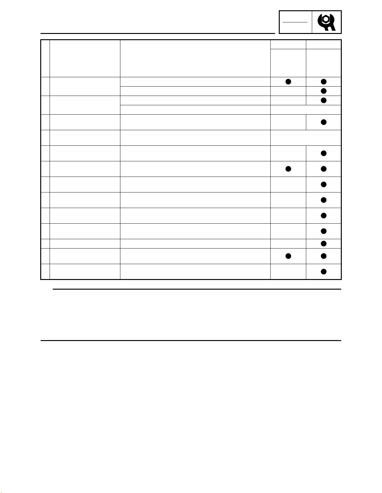
4. Measure:
• Spark plug gap
Out of specification → Regap.
Use a wire thickness gauge.
ADJ
Spark plug gap:
0.7 ~ 0.8 mm (0.028 ~ 0.031 in)
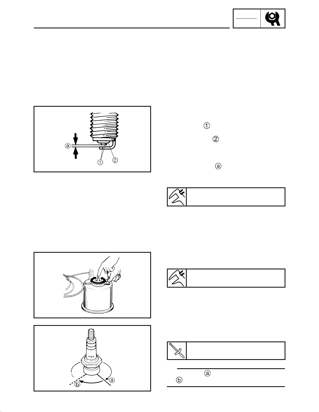
If necessary, clean the spark plugs with a
spark plug cleaner.
Standard spark plug:
NGK CR8E (NGK)
Before installing a spark plug, clean the gasket
surface and spark plug surface.
5. Install:
• Spark plugs
Spark plug:
13 Nm (1.3 m•kgf, 9.4 ft•lbf)
TIP
Finger-tighten the spark plug before torquing it to specification.
2-3
SPARK PLUGS/FUEL LINE INSPECTION /
COOLING SYSTEM
6. Install:
• Coolant recovery (RS90GTZ/RS90LTGTZ)
Refer to “HEAT EXCHANGER” in CHAPTER 6.
• Headlight assembly
• Top cover
Refer to “COWLINGS” in CHAPTER 3.
FUEL LINE INSPECTION
1. Remove:
• Top cover
• Headlight assembly
Refer to “COWLINGS” in CHAPTER 3.
• Fuel tank cover
Refer to “FUEL TANK” in CHAPTER 5.
2. Inspect:
• Fuel hose
Cracks/ damage → Replace.
3. Install:
• Fuel tank cover
Refer to “FUEL TANK” in CHAPTER 5.
• Headlight assembly
• Top cover
Refer to “COWLINGS” in CHAPTER 3.
INSP
ADJ
COOLING SYSTEM
Coolant replacement
1. Place the snowmobile on a level surface.
2. Remove:
• Side cover (right)
• Side under cover (right)
Refer to “COWLINGS” in CHAPTER 3.
2-4
INSP
COOLING SYSTEM
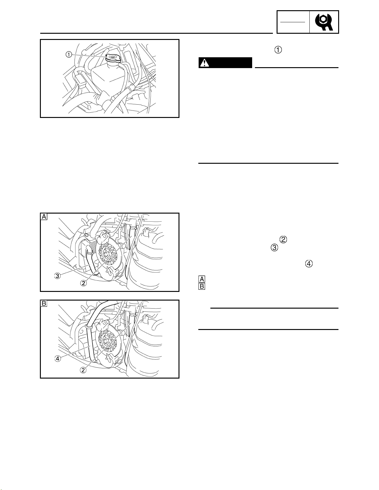
3. Remove:
• Coolant reservoir cap
WARNING
Do not remove the coolant reservoir cap
when the engine is hot. Pressurized scalding hot fluid and steam may be blown out,
which could cause serious injury. When the
engine has cooled, place a thick rag or a
towel over the coolant reservoir cap. Slowly
turn the cap counterclockwise until it stop.
This allows any residual pressure to
escape. When the hissing sound has
stopped, press down on the cap while turning it counterclockwise to remove it.
ADJ
4. Place an open container under the coolant
hoses.
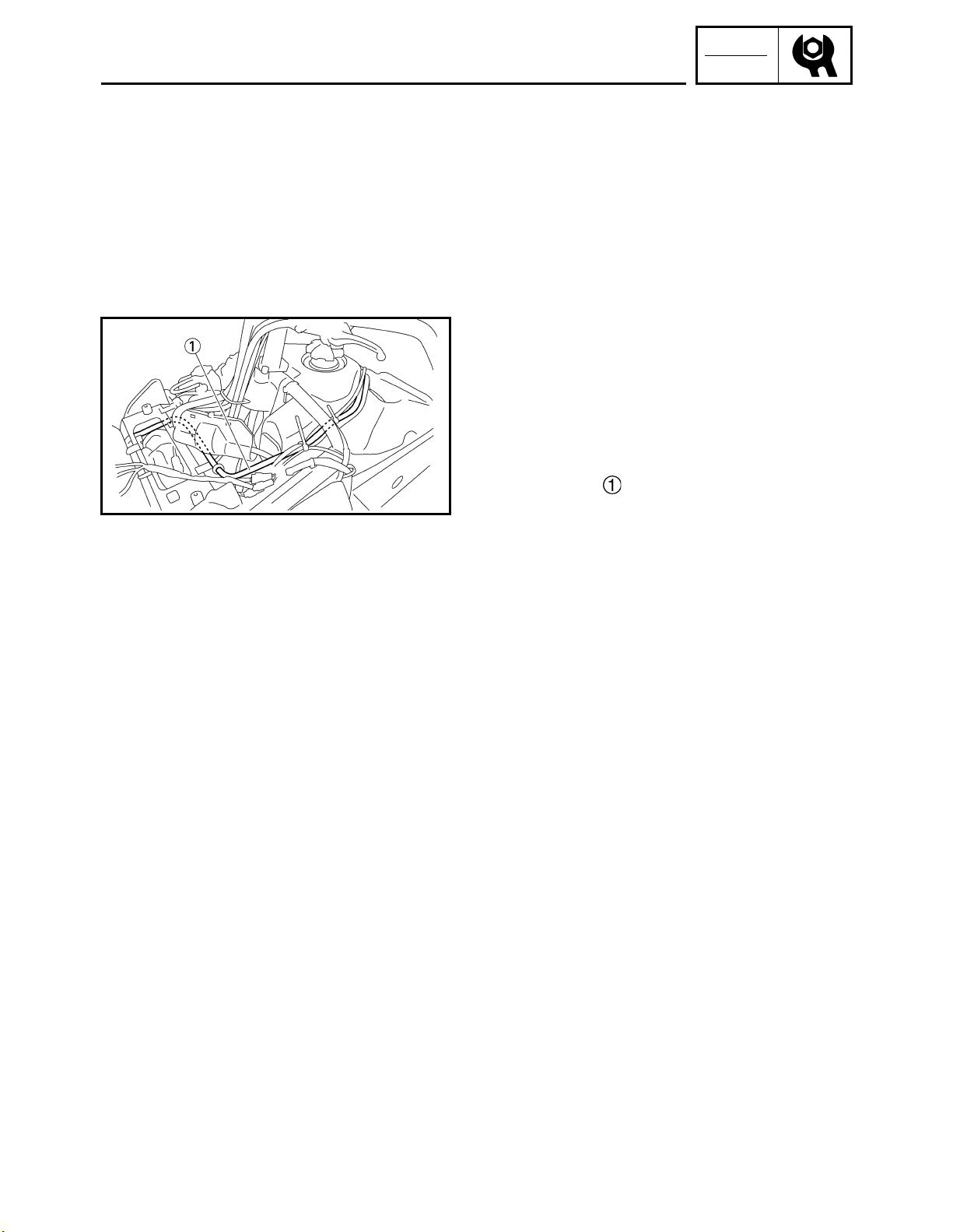
5. Disconnect:
• Thermostat outlet hose
• Radiator outlet hose
(RS90GTZ/RS90LTGTZ)
• Right heat exchanger inlet hose
(RST90GTZ)
RS90GTZ/RS90LTGTZ
RST90GTZ
6. Drain the coolant.
TIP
Lift up the tail of the snowmobile to drain the
coolant.
2-5
INSP
COOLING SYSTEM
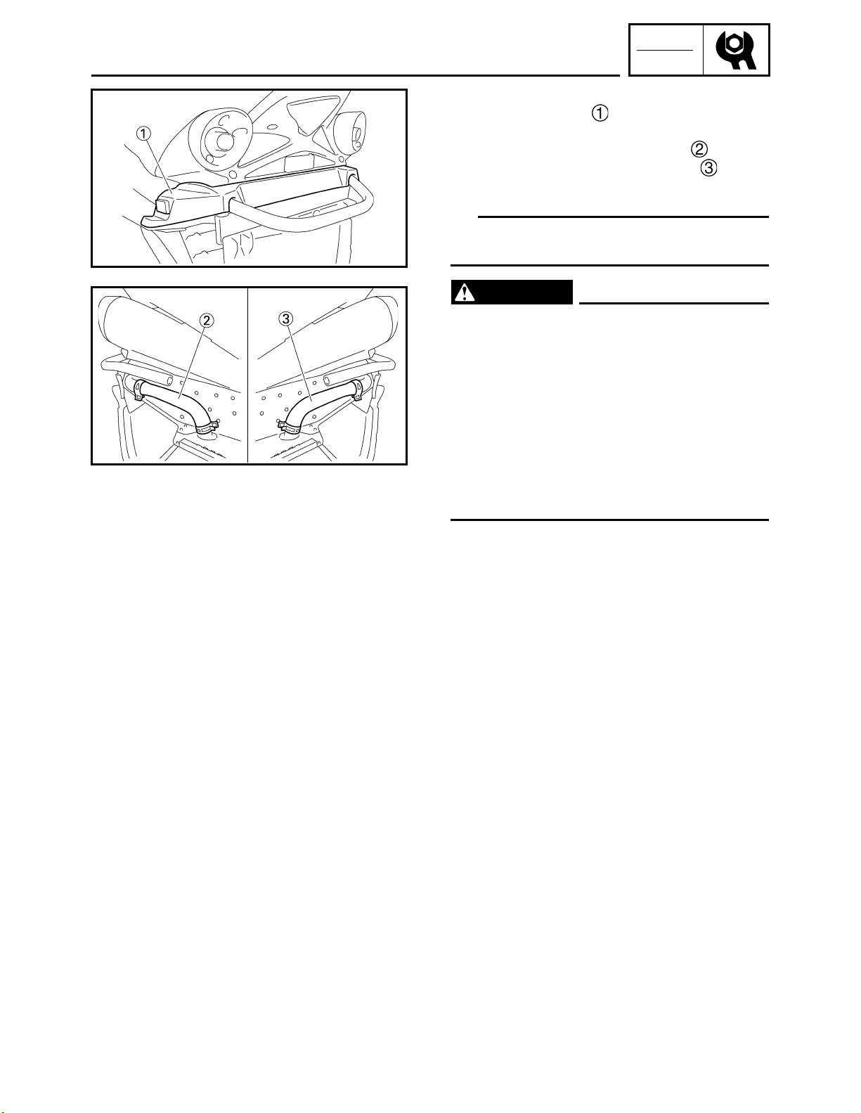
7. Remove:
• Lower rear cover
8. Disconnect:
• Rear heat exchanger inlet hose
• Rear heat exchanger outlet hose
9. Drain the coolant.
TIP
Lift up the front of the snowmobile to drain the
coolant completely.
WARNING
Coolant is poisonous. It is harmful or fatal
if swallowed.
• If coolant is swallowed, induce vomiting
immediately and get immediate medical
attention.
• If coolant splashes in your eyes, thoroughly wash them with water and consult
a doctor.
• If coolant splashes on your skin or
clothes, quickly wash it away with soap
and water.
ADJ
10.Connect:
• Thermostat outlet hose
• Radiator outlet hose
(RS90GTZ/RS90LTGTZ)
• Right heat exchanger inlet hose
(RST90GTZ)
11.Connect:
• Rear heat exchanger inlet hose
• Rear heat exchanger outlet hose
2-6
COOLING SYSTEM
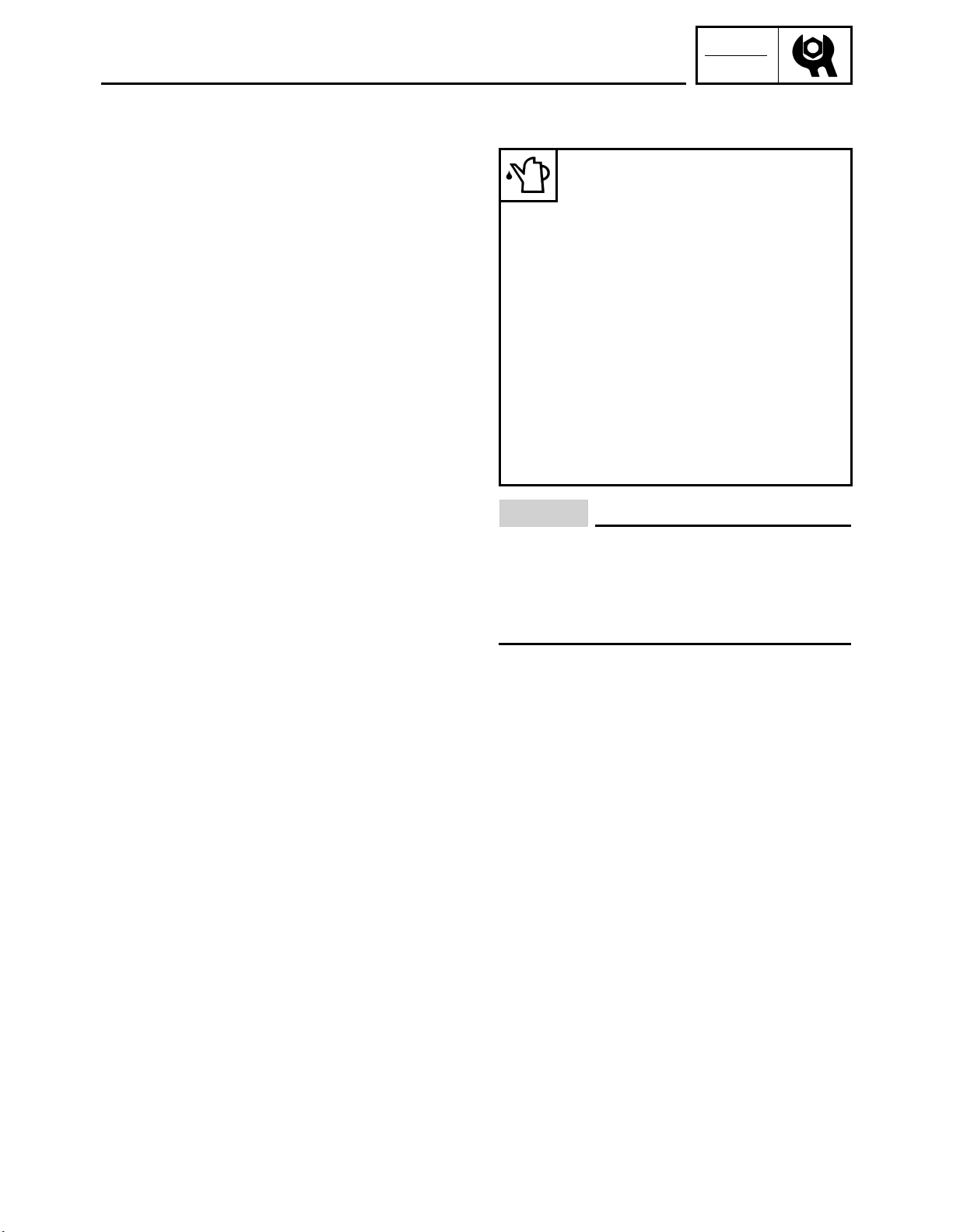
12.Fill:
• Cooling system
Recommended antifreeze:
High quality ethylene glycol
antifreeze containing corrosion
inhibitors
Antifreeze/water mixing ratio:
3 : 2 (60% : 40%)
Total amount:
RS90GTZ
5.6 L (5.92 US qt,
4.93 Imp.qt)
RS90LTGTZ
6.1 L (6.45 US qt,
5.37 Imp.qt)
RST90GTZ
5.4 L (5.71 US qt,
4.75 Imp.qt)
INSP
ADJ
NOTICE
• Hard water or salt water is harmful to
engine parts. If soft water is not available,
use boiled or distilled water.
• Do not use water containing impurities or
oil.
13.Bleed the air from the cooling system.
Refer to “Air bleeding”
2-7
 Loading...