

Yamaha RS90GTA, RS90LTGTA, RST90A, RST90GTA Owner's Manual
OWNER’S MANUAL
Read this manual carefully
before operating this vehicle.
RS90GTA
LIT-12628-02-95
RS90LTGTA
RST90A
RST90GTA
8JA-28199-11
ESU10041
Read this manual carefully before operating this vehicle. This manual
should stay with this vehicle if it is sold.
ESU10121
Congratulations on your purchase of a
Yamaha snowmobile. This model is the result
of Yamaha’s vast experience in the production of fine sporting and touring snowmobiles.
It represents the high degree of craftsmanship
and reliability that have made Yamaha a leader in these fields.
This manual will give you an understanding of
the operation, inspection, and basic maintenance of this snowmobile. If you have any
questions concerning the operation or maintenance of your snowmobile, please consult a
Yamaha dealer.
Yamaha continually seeks advancements in
product design and quality. Therefore, while
this manual contains the most current product
information available at the time of printing,
there may be minor discrepancies between
your snowmobile and this manual. If there is
any question concerning this manual, please
consult a Yamaha dealer.
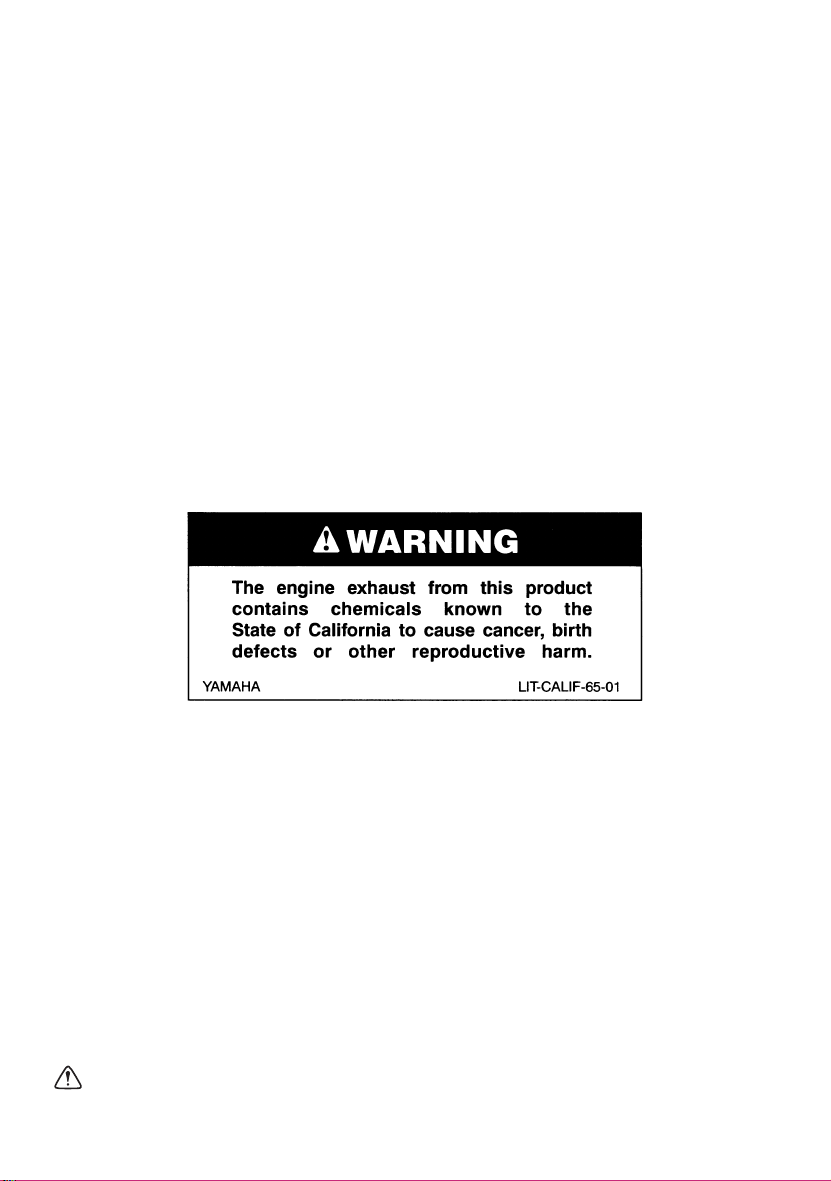
EWS00670
WARNING
Please read this manual carefully before
operating this snowmobile. Do not attempt
to operate this snowmobile until you have
attained adequate knowledge of its controls and operating features.
Regular inspections and careful maintenance, along with good operating techniques, will help ensure that you safely
enjoy the capabilities and reliability of this
snowmobile.
Introduction
RS90GTA
RS90LTGTA
RST90A
RST90GTA
OWNER’S MANUAL
©2010 by Yamaha Motor Corporation,
U.S.A.
1st Edition, June 2010
All rights reserved.
Any reprinting or unauthorized use
without the written permission of
Yamaha Motor Corporation, U.S.A.
is expressly prohibited.
Printed in Japan.
P/N LIT-12628-02-95
Important manual information
ESU10151
Particularly important information is distinguished in this manual by the following notations.
This is the safety alert symbol. It is used
to alert you to potential personal injury hazards. Obey all safety messages that follow
this symbol to avoid possible injury or death.
EWS00021
WARNING
A WARNING indicates a hazardous situation which, if not avoided, could result in
death or serious injury.
ECS00011
NOTICE
A NOTICE indicates special precautions
that must be taken to avoid damage to the
snowmobile or other property.
TIP
A TIP provides key information to make procedures easier or clearer.

Contents
Location of the important labels ..... 1
Safety information ............................ 6
Description ........................................ 8
Control functions ............................ 11
Main switch .................................. 11
Starter (choke) lever (RST90) ...... 11
Throttle lever ................................ 11
Throttle override system
(T.O.R.S.) .................................. 12
Multi-function meter unit ............... 13
High beam indicator light .............. 16
Low coolant temperature indicator
light ............................................ 17
Fuel meter and grip/thumb warmer
level indicator ............................ 18
Fuel level warning indicator .......... 20
Oil level warning indicator ............ 21
Coolant temperature warning
indicator ..................................... 21
Self-diagnosis device ................... 22
Engine stop switch ....................... 22
Headlight beam switch
“LIGHTS” ................................... 23
Grip/thumb warmer adjusting
switch ........................................ 23
Auxiliary DC jack .......................... 24
Helmet shield heater jack
(RS90GT/ RS90LTGT/
RST90GT) ................................. 25
Brake lever ................................... 25
Parking brake lever ...................... 26
Shift lever ..................................... 26
Drive guard ................................... 27
V-belt holders ............................... 28
Passenger grips (RST90GT) ........ 29
Passenger grip warmer switch
(RST90 / RST90GT) ................. 29
Passenger footrests
(RST90 / RST90GT) ................. 30
Backrest (RST90 / RST90GT) ..... 30
Storage compartment (RS90GT /
RS90LTGT / RST90GT) ........... 31
Storage areas (RST90) ................ 33
Tow hitch bracket
(RST90 / RST90GT) ................. 35
Fuel .............................................. 36
Suspension .................................. 37
Pre-operation checks ..................... 46
Pre-operation check list ............... 46
Operation ......................................... 48
Starting the engine ....................... 48
Break-in ........................................ 50
Riding your snowmobile ............... 50
Maximizing drive track life ............ 54
Driving .......................................... 55
Stopping the engine ..................... 56
Transporting ................................. 56
Periodic maintenance and
adjustment....................................... 58
Periodic maintenance chart for
the emission control system ..... 59
General maintenance and
lubrication chart ........................ 60
Tool kit ......................................... 62
Removing and installing
the shroud and covers (RS90GT /
RS90LTGT / RST90GT) ........... 63
Opening and closing the shroud
and removing and installing
the right side cover (RST90) ..... 67
Checking the spark plugs ............. 68
Adjusting the engine idling speed
(RST90) .................................... 69
Adjusting the throttle lever free
play ........................................... 69
Checking the throttle override
system (T.O.R.S.) ..................... 72
Checking the air filter ................... 73

Contents
Carburetors (RST90) .................... 77
High-altitude settings .................... 77
Valve clearance ............................ 77
Engine oil and oil filter cartridge ... 77
Cooling system ............................. 83
V-belt ............................................ 88
Drive chain housing ...................... 91
Brake and parking brake .............. 92
Extrovert drive sprocket
(RS90GT / RS90LTGT) ............. 95
Skis and ski runners ..................... 95
Steering system ........................... 96
Drive track and slide runners ....... 98
Lubrication .................................. 102
Replacing a headlight bulb ......... 103
Adjusting the headlight beams ... 107
Fittings and fasteners ................. 108
Battery ........................................ 108
Replacing a fuse ........................ 109
Troubleshooting ........................... 116
Storage .......................................... 120
Specifications ............................... 122
Consumer information.................. 125
Identification number records ..... 125
Vehicle Emission Control
Information label ...................... 126
YAMAHA MOTOR
CORPORATION, U.S.A.
SNOWMOBILE LIMITED
WARRANTY............................. 127
YAMAHA EXTENDED SERVICE
(Y.E.S.)..................................... 130
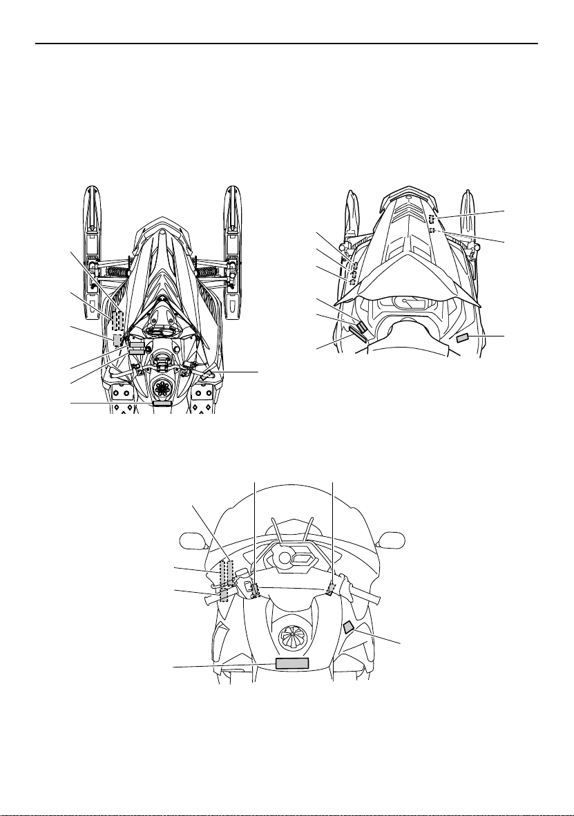
Location of the important labels
ESU10216
Read and understand all of the labels on your vehicle. They contain important information for
safe and proper operation of your vehicle. Never remove any labels from your vehicle. If a label
becomes difficult to read or comes off, a replacement label is available from your Yamaha dealer.
RS90GT / RS90LTGT
8
5
4
3
2
1
RST90GT
5
4
RST90
6
5
8
7
4
3
2
9
1
9
3
2
8
9
1
1
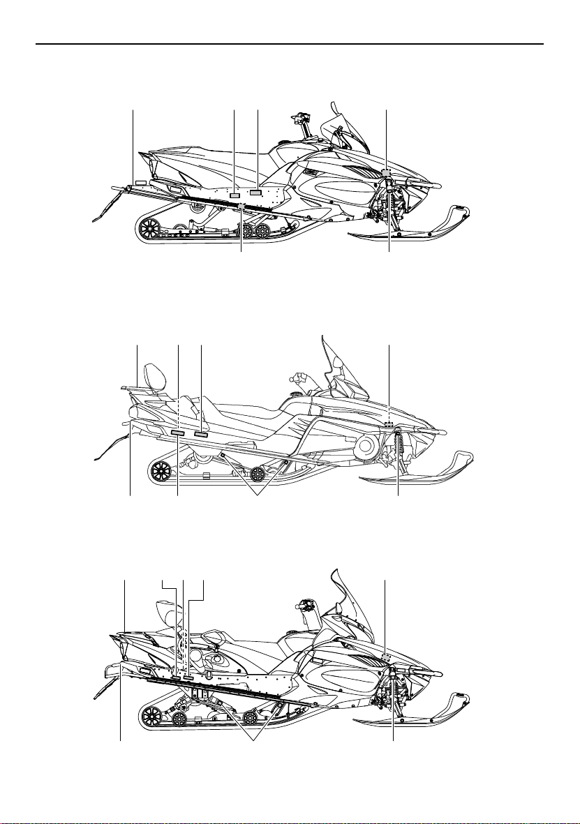
Location of the important labels
RS90GT / RS90LTGT
RST90
13
16
14
15
10
11
10
17
11
17
12
17
12
17
RST90GT
2
14
16
10
15
11
17
12
17
Location of the important labels
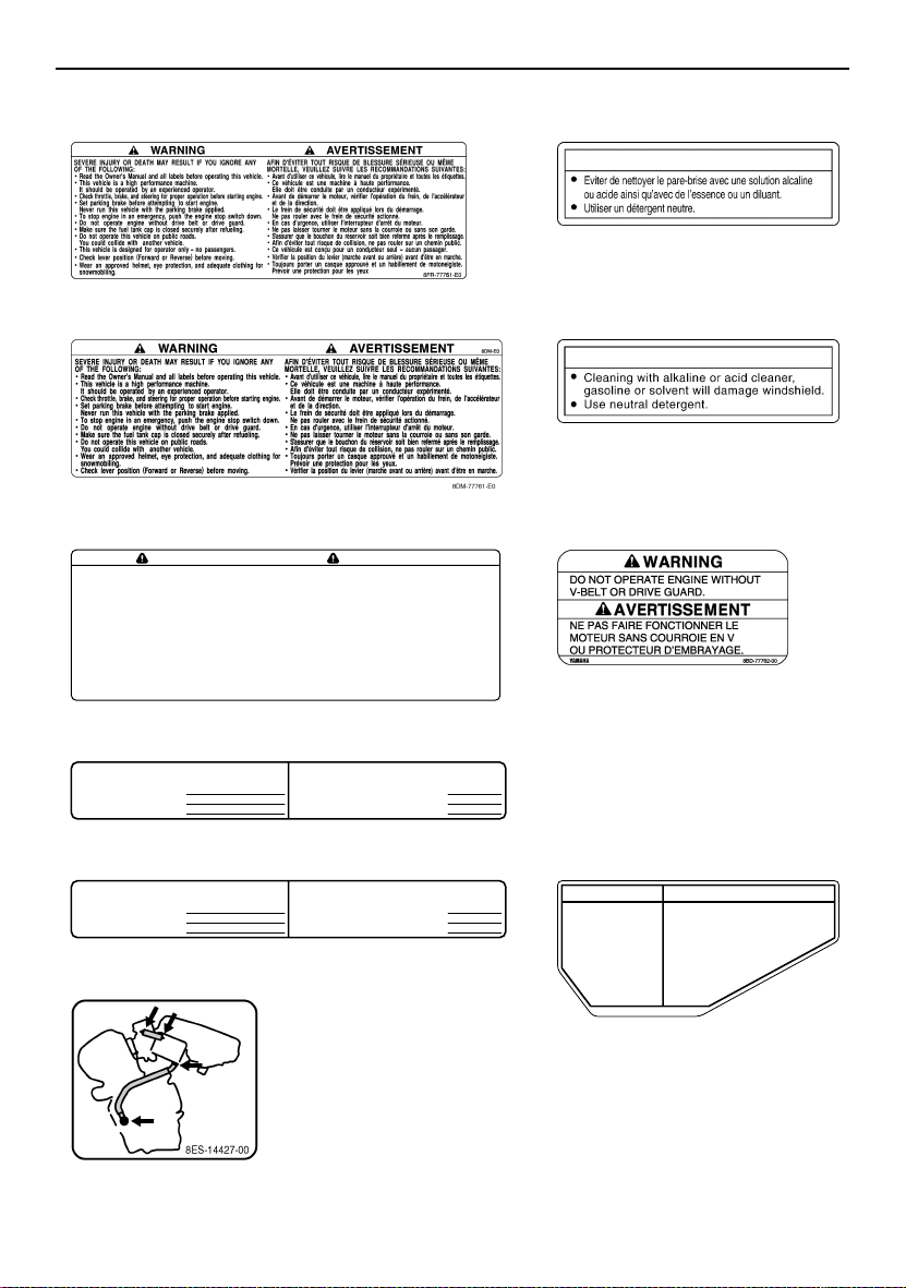
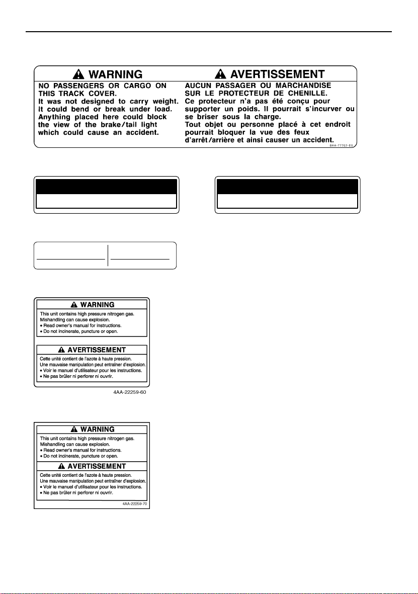
1 RS90GT / RS90LTGT 2
1 RST90 3
1 RST90GT 4
SEVERE INJURY OR DEATH MAY RESULT IF YOU IGNORE ANY OF
THE FOLLOWING:
•
Read the Owner’s Manual and all labels before operating this vehicle.
• This vehicle is a high performance machine.
It should be operated by an experienced operator.
Check throttle, brake, and steering for proper operation before starting engine.
•
• Set parking brake before attempting to start engine.
Never run this vehicle with the parking brake applied.
To stop engine in an emergency, push the engine stop switch down.
•
• Do not operate engine without drive belt or drive guard.
• Make sure the fuel tank cap is closed securely after refueling.
• Do not operate this vehicle on public roads.
You could collide with another vehicle.
• Check lever position (Forward or Reverse) before moving.
• Weal an approved helmet, eye protection, and adequate clothing
for snowmobiling.
WARNING AVERTISSEMENT
AFIN D’ÉVITER TOUT RISQUE DE BLESSURE SÉRIEUSE OU MÊME MORTELLE,
VEUILLEZ SUIVRE LES RECOMMANDATIONS SUIVANTES:
•
Avant d’utiliser ce véhicule, lire le manuel du propriétaire et toutes les étiquettes.
• Ce véhicule est une machine à haute performance.
Elle doit être conduite par un conducteur expérimenté.
Avant de démarrer le moteur, vérifier l’opération du frein, de l’accélérateur
•
et de la direction.
• Le frein de sécurité doit être appliqué lors du démarrage.
Ne pas rouler avec le frein de sécurité actionné.
• En cas d’urgence, utiliser l’interrupteur d’arrêt du moteur.
• Ne pas laisser tourner le moteur sans la courroie ou sans son garde.
S’assurer que le bouchon du réservoir soit bien refermé après le remplissage.
•
•
Afin d’éviter tout risque de collision, ne pas rouler sur un chemin public.
•
Vérifier la position du levier (marche avant ou arrière) avant d’être en marche.
•
Toujours porter un casque approuvé et un habillement de motoneigiste.
Prévoir une protection pour les yeux.
8HF-77761-E0
ATTENTION
8ET-2815K-10
NOTICE
8ET-2815K-00
5 RS90GT / RS90LTGT / RST90GT
TUNE-UP SPECIFICATIONS
ENGINE
1.SPARK PLUG
2.SPARK PLUG GAP
3.IDLE SPEED
TUNE-UP SPECIFICATIONS
ENGINE
1.SPARK PLUG
2.SPARK PLUG GAP
3.IDLE SPEED
CR8E(NGK)
0.7 ~ 0.8 mm (0.028 ~ 0.031 in)
1300 ± 50 r/min
CR8E(NGK)
0.7 ~ 0.8 mm (0.028 ~ 0.031 in)
1400 ± 100 r/min
SPECIFICATION S DE LA MISE AU P OINT
MOTEUR
1.TYPE DE BOUGIE
2.ECARTEMENT DES ÉLECTRODES
3.RÉGIME DE RALENTI
SPECIFICATION S DE LA MISE AU P OINT
MOTEUR
1.TYPE DE BOUGIE
2.ECARTEMENT DES ÉLECTRODES
3.RÉGIME DE RALENTI
CR8E(NGK)
0.7 ~ 0.8 mm
1300 ± 50 r/min
CR8E(NGK)
0.7 ~ 0.8 mm
1400 ± 100 r/min
7 RST90
8HF-1417E-00
8ES-1417E-00
8HF
6 RST905 RST90
8ES
NOTICE ATTENTION
Severe engine damage
can result from oil loss if
crankcase breather hoses
are not installed correctly.
Inspect hoses and clamps
for correct installation
after battery service or
air box removal.
See Service Manual.
Des dommages graves risquent de survenir par
suite de fuites d’huile résultant d’un mauvais
branchement des tuyaux de reniflard du carter.
Après l’entretien de la batterie ou après la
dépose de I’épurateur d’air, assurezvous que les brides et les tuyaux
sont installès correctement.
Consultez le manuel
d’entretien.
8GS-2815J-E0
3
Location of the important labels
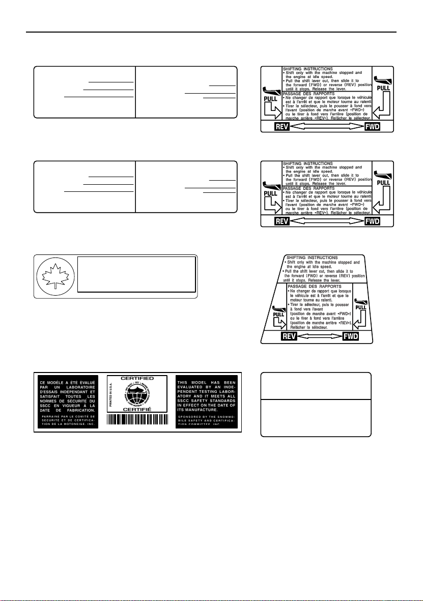
8 RS90GT / RS90LTGT / RST90 9 RS90GT / RS90LTGT
TUNE-UP SPECIFICATIONS
DRIVE
1. CHAIN CASE OIL Q’TY
2. CHAIN CASE OIL TYPE
3. TRACK TENSION
30 ~ 35 mm (1.18 ~ 1.38 in)/100 N (10 kg, 22 lb)
* FOR MORE INFO: SEE SERVICE MANUAL FOR THIS
MODEL.
* SPECIFICATIONS SUBJECT TO CHANGE WITHOUT
NOTICE.
250 cm³ (8.5 oz)
GL-3 75W or 80W
SPECIFICATION S DE LA MISE AU POINT
ENTRAÎNEMENT
1. CAPACITÉ D’HUILE DU CARTER DE CHAÎNE
2. TYPE D’HUILE DU CARTER DE CHAÎNE
3. FLÈCHE DE LA CHENILLE
* POUR PLUS DE DÉTAIL: VOIR LE MANUEL D’ATELIER
POUR CE MODÈLE.
* LES CARACTÉRISTIQUE TECHNIQUES SONT
SUSCEPTIBLES DE CHANGER SANS NOTIFICATION
PRÉALABLE.
250 cm³
GL-3 75W or 80W
30 ~ 35 mm/100 N (10 kg)
8ES-47578-00
9 RST908 RST90GT
TUNE-UP SPECIFICATIONS
DRIVE
1. CHAIN CASE OIL Q’TY
2. CHAIN CASE OIL TYPE
3. TRACK TENSION
20 ~ 25 mm (0.79 ~ 0.98 in)/100 N (10 kg, 22 lb)
* FOR MORE INFO: SEE SERVICE MANUAL FOR THIS
MODEL.
* SPECIFICATIONS SUBJECT TO CHANGE WITHOUT
NOTICE.
250 cm³ (8.5 oz)
GL-3 75W or 80W
SPECIFICATION S DE LA MISE AU POINT
ENTRAÎNEMENT
1. CAPACITÉ D’HUILE DU CARTER DE CHAÎNE
2. TYPE D’HUILE DU CARTER DE CHAÎNE
3. FLÈCHE DE LA CHENILLE
* POUR PLUS DE DÉTAIL: VOIR LE MANUEL D’ATELIER
POUR CE MODÈLE.
* LES CARACTÉRISTIQUE TECHNIQUES SONT
SUSCEPTIBLES DE CHANGER SANS NOTIFICATION
PRÉALABLE.
250 cm³
GL-3 75W or 80W
20 ~ 25 mm/100 N (10 kg)
8HF-47578-00
8ER-77763-E0
9 RST90GT10
A
D
N
A
A
C
•
S
S
V
M
C
•
T
R
A
This spark ignition system meets all requirements of the
•
N
Canadian Interference Causing Equipment Regulations.
S
V
A
C
Ce système d’allumage par étincelle de véhicule
506
•
respecte toutes les exigences du Règlement sur le
T
matériel brouilleur du Canada.
R
O
N
P
S
3JK-82377-10
8HF-77763-E0
8FR-77763-E0
8ER-E0
1211
JUMPER CABLE CONNECTION LEADS
• For connecting procedures, refer to
Owner’s Manual.
FILS DE BRANCHEMENT DES CÂBLES
DE DÉMARRAGE
•
Effectuer le branchement des câbles
de démarrage conformément aux
88C-77769-00
instructions du Manuel du propriétaire.
4
8FA-E0
8FA-2389C-E0
Location of the important labels
13 RS90LTGT
14 RST90 / RST90GT 15 RST90 / RST90GT
LOAD LIMIT / CHARGE LIMITE
10kg {22lbs}
8ET-24897-00
16 RST90 / RST90GT
MAX. TOWING FORCE
FORCE DE REMORQUAGE MAX.
1176 N (120 kgf), 264 lbf
MAX. VERTICAL FORCE
FORCE VERTICALE MAX.
147 N (15 kgf), 33 lbf
8GS-2817S-E0
17 RST90
17 RS90GT / RS90LTGT
LOAD LIMIT / CHARGE LIMITE
20kg {44lbs}
8FM-24897-01
5

Safety information
ESU10193
As the vehicle’s owner, you are responsible
for the safe and proper operation of your
snowmobile. When you ride your snowmobile, you must know and use the following for
your safety. Severe injury or death may result
if you ignore any of the following.
Before you operate your snowmobile
● Read the Owner’s Manual and all labels.
Become familiar with all of the operating
controls and their function. Consult a
Yamaha dealer about any control or function you do not understand.
● Wear protective clothing. Wear an ap-
proved helmet, and a face shield or goggles. Also, wear a good quality snowmobile
suit, boots, and a pair of gloves or mittens
that will permit use of your thumbs and fingers for operation of the controls.
● Apply the parking brake before starting the
engine. Never drive the snowmobile with
the parking brake applied. This may overheat the brake disc and reduce braking ability.
While using your snowmobile
● This snowmobile was not manufactured for
use on public streets, roads, or highways.
Such use is prohibited by law, and you
could collide with another vehicle.
● RS90GT and RS90LTGT are designed to
carry the OPERATOR ONLY. Passengers
are prohibited. Carrying a passenger can
cause loss of control.
● Do not operate the snowmobile after or
while drinking alcohol or taking drugs. Your
ability to operate the snowmobile is reduced by the influence of alcohol or drugs.
Prepare your snowmobile
● Perform the pre-operation checks each
time you use the vehicle to make sure it is
in safe operating condition. Failure to inspect or maintain the vehicle properly increases the possibility of an accident or
equipment damage. See page 46 for a list
of pre-operation checks.
6
● Be careful where you ride. There may be
obstacles hidden beneath the snow. Stay
on established trails to minimize your exposure to hazards. Ride slowly and cautiously
when you ride off of established trails. Hitting a rock or stump, or running into wires
could cause an accident and injury.
● This snowmobile is not designed for use on
surfaces other than snow or ice. Use on dirt,
sand, grass, rocks, or bare pavement may
cause loss of control and may damage the
snowmobile.
● Always ride with other snowmobilers when
going on a ride. You may need help if you
run out of fuel, have an accident, or damage
your snowmobile.

Safety information
● Many surfaces such as ice and hardpacked
snow require much longer stopping distances. Be alert, plan ahead and begin decelerating early. The best braking method on
most surfaces is to release the throttle and
apply the brake gently—not suddenly.
Avoid carbon monoxide poisoning
All engine exhaust contains carbon monoxide, a deadly gas. Breathing carbon monoxide
can cause headaches, dizziness, drowsiness,
nausea, confusion, and eventually death.
Carbon monoxide is a colorless, odorless,
tasteless gas which may be present even if
you do not see or smell any engine exhaust.
Deadly levels of carbon monoxide can collect
rapidly and you can quickly be overcome and
be unable to save yourself. Also, deadly levels of carbon monoxide can linger for hours or
days in enclosed or poorly-ventilated areas. If
you experience any symptoms of carbon
monoxide poisoning, leave the area immediately, get fresh air, and SEEK MEDICAL
TREATMENT.
● Do not run the engine indoors. Even if you
try to ventilate engine exhaust with fans or
open windows and doors, carbon monoxide
can rapidly reach dangerous levels.
● Do not run the engine in poorly ventilated or
partially enclosed areas such as barns, garages, or carports.
● Do not run the engine outdoors where en-
gine exhaust can be drawn into a building
through openings such as windows and
doors.
Genuine Yamaha Accessories
Choosing accessories for your snowmobile is
an important decision. Genuine Yamaha Accessories, which are available only from a
Yamaha dealer, have been designed, tested,
and approved by Yamaha for use on your
snowmobile. Many companies with no connection to Yamaha manufacture parts and ac-
cessories or offer other modifications for
Yamaha vehicles. Yamaha is not in a position
to test the products that these aftermarket
companies produce. Therefore, Yamaha can
neither endorse nor recommend the use of
accessories not sold by Yamaha or modifications not specifically recommended by
Yamaha, even if sold and installed by a
Yamaha dealer.
Maintenance and storage
● When laying the snowmobile on its side for
maintenance, use a suitable stand to keep
it in a stable and level position.
● Do not leave the snowmobile on its left side
for an extended period of time. Fuel may
leak out from the fuel breather hose.
● Do not allow anyone to stand behind the
snowmobile when starting, inspecting, or
adjusting the snowmobile. A broken track,
track fittings, or debris thrown by the track
could be dangerous to the operator or bystanders.
● Modifications made to the snowmobile not
approved by Yamaha, or the removal of
original equipment may render your snowmobile unsafe for use, which may cause severe personal injury. Modifications may
also make the snowmobile illegal to use.
● Never store the snowmobile with fuel in the
fuel tank inside a building where ignition
sources are present such as hot water and
space heaters, an open flame, sparks,
clothes dryers, and the like. Allow the engine to cool off before storing the snowmobile in an enclosed space.
7
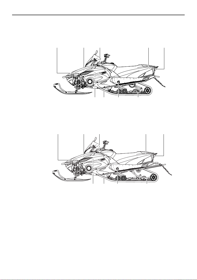
Description
ESU10261
RS90GT
RS90LTGT
1,2,3 4 5,6,7 8,9 10
11121314
1,2,3
4 5,6,7 8,9 10
1. Battery
2. Main fuse
3. Air filter
4. Oil filler cap
5. Fuse box
6. Coolant reservoir
7. Coolant recovery tank
8. Storage compartment
9. Tool kit
10. Tail/brake light
11. Slide rail suspension
12. Rear shock absorber damping force remote
adjusting dial
8
11121314
13. Drive track
14. V-belt holder
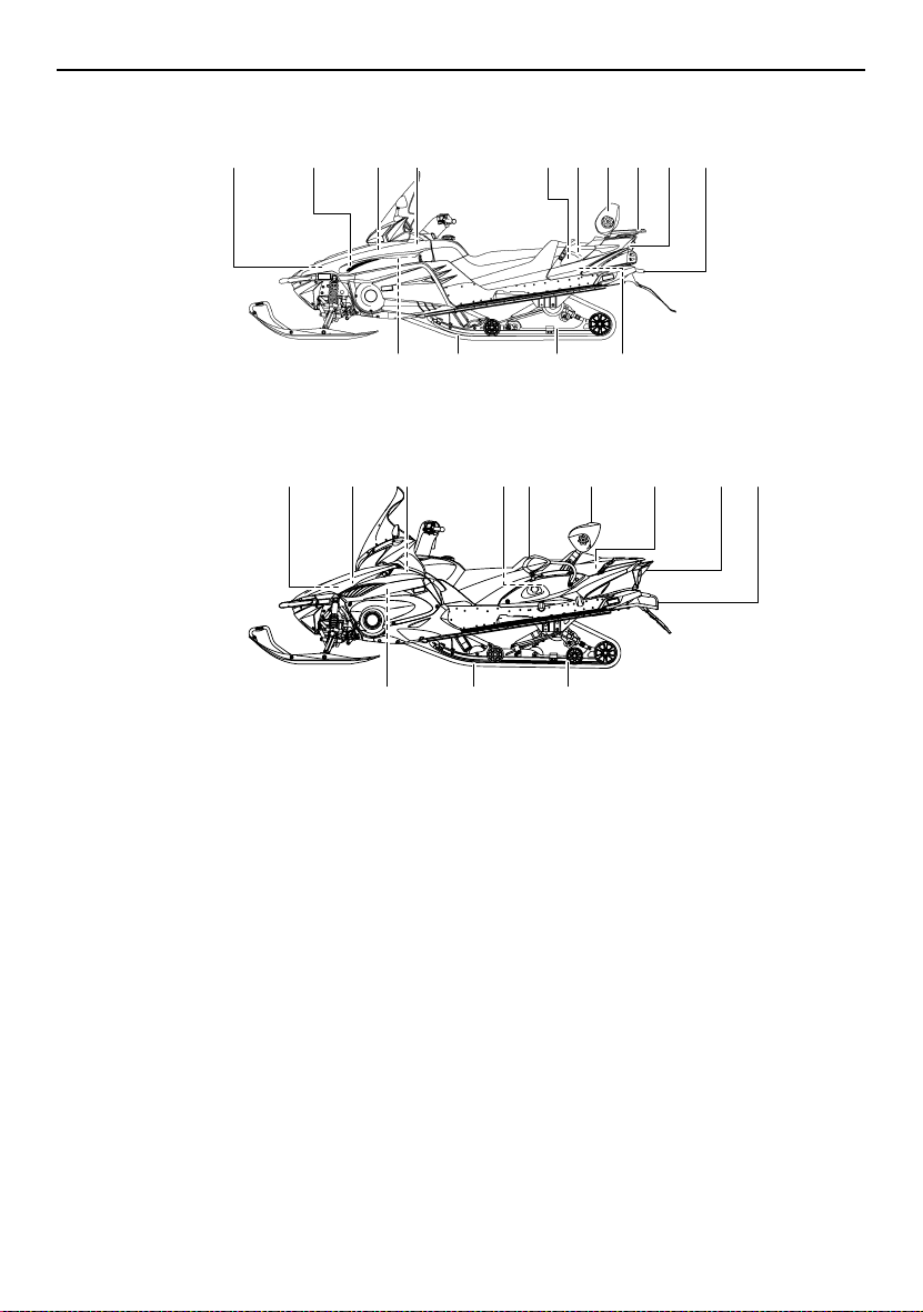
RST90
10,12 1,2,3,4 5,620 7 8 9 1913
151617
18
RST90GT
1,2,3 4 7 8 9 10,11,12 13
5,6
Description
14
14
1. Battery
2. Main fuse
3. Air filter
4. Oil filler cap
5. Fuse box
6. Coolant reservoir
7. Passenger grip warmer switch
8. Passenger grip
9. Backrest
10. Storage compartment
11. Storage pouch (RST90GT)
12. Tool kit
13. Tail/brake light
14. Tow hitch bracket
15. Slide rail suspension
151617
16. Drive track
17. V-belt holder
18. Solo touring storage area (RST90)
19. Rear carrier (RST90)
20. Throttle stop screw (RST90)
9
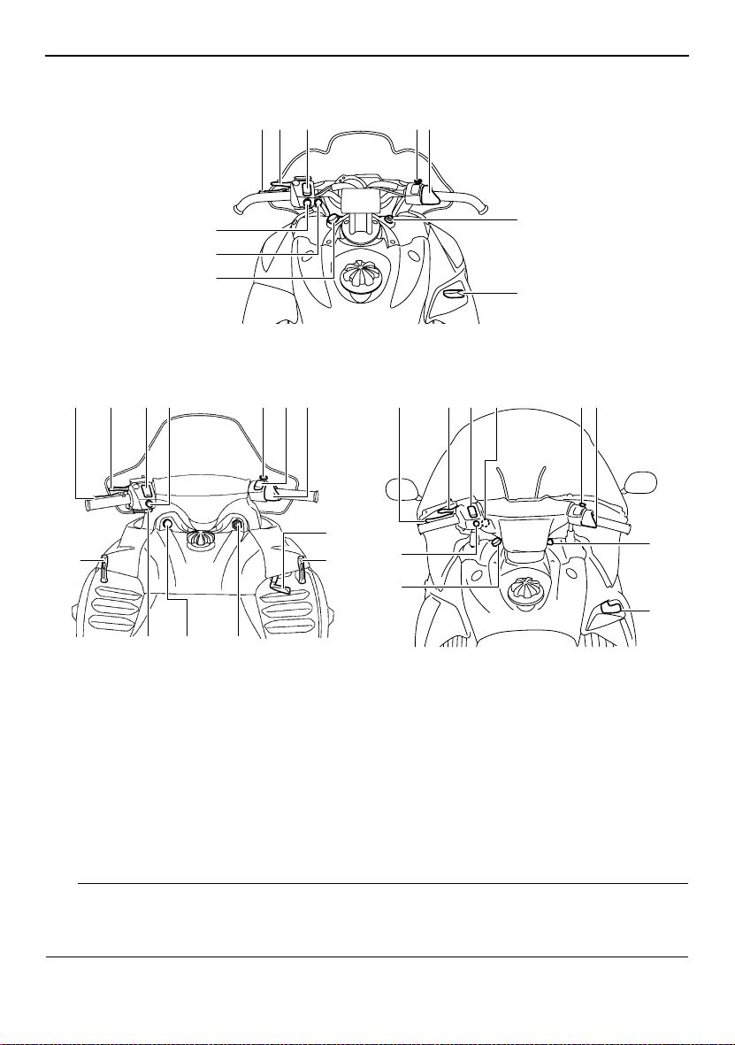
Description
RS90GT / RS90LTGT
1
23 78
12
6
11
12412
5 87
13
14 911
1. Brake lever
2. Parking brake lever
3. Grip/thumb warmer adjusting switch
(RS90GT / RS90LTGT / RST90GT)
4. Grip warmer adjusting switch (RST90)
5. Thumb warmer adjusting switch (RST90)
6. Helmet shield heater jack (RS90GT /
RS90LTGT / RST90GT)
7. Engine stop switch
10
13
9
10
RST90GT RST90
1 236 78
12
11
8. Throttle lever
9. Main switch
10. Shift lever
11. Auxiliary DC jack
12. Headlight beam switch
13. Shroud latch (RST90)
14. Starter (choke) lever (RST90)
9
10
TIP
● The snowmobile you have purchased may differ slightly from those shown in the figures of
this manual.
● Design and specifications are subjected to change without notice.
10
ESU13740
Main switch
The main switch controls the ignition and
lighting systems. The various positions are
described below.
2
13
1. Off
2. On
3. Start
Off
The ignition circuit is switched off.
The key can be removed only in this position.
On
The ignition circuit is switched on.
Start
The starting circuit is switched on.
The starter motor cranks the engine.
NOTICE: Release the switch immediately
after the engine starts.
[ECS00021]
TIP
● RS90GT / RS90LTGT / RST90GT: The
headlights and taillight come on after the
engine is started.
● RST90: The headlights, meter lighting, and
taillights come on after the engine is started.
ESU10301
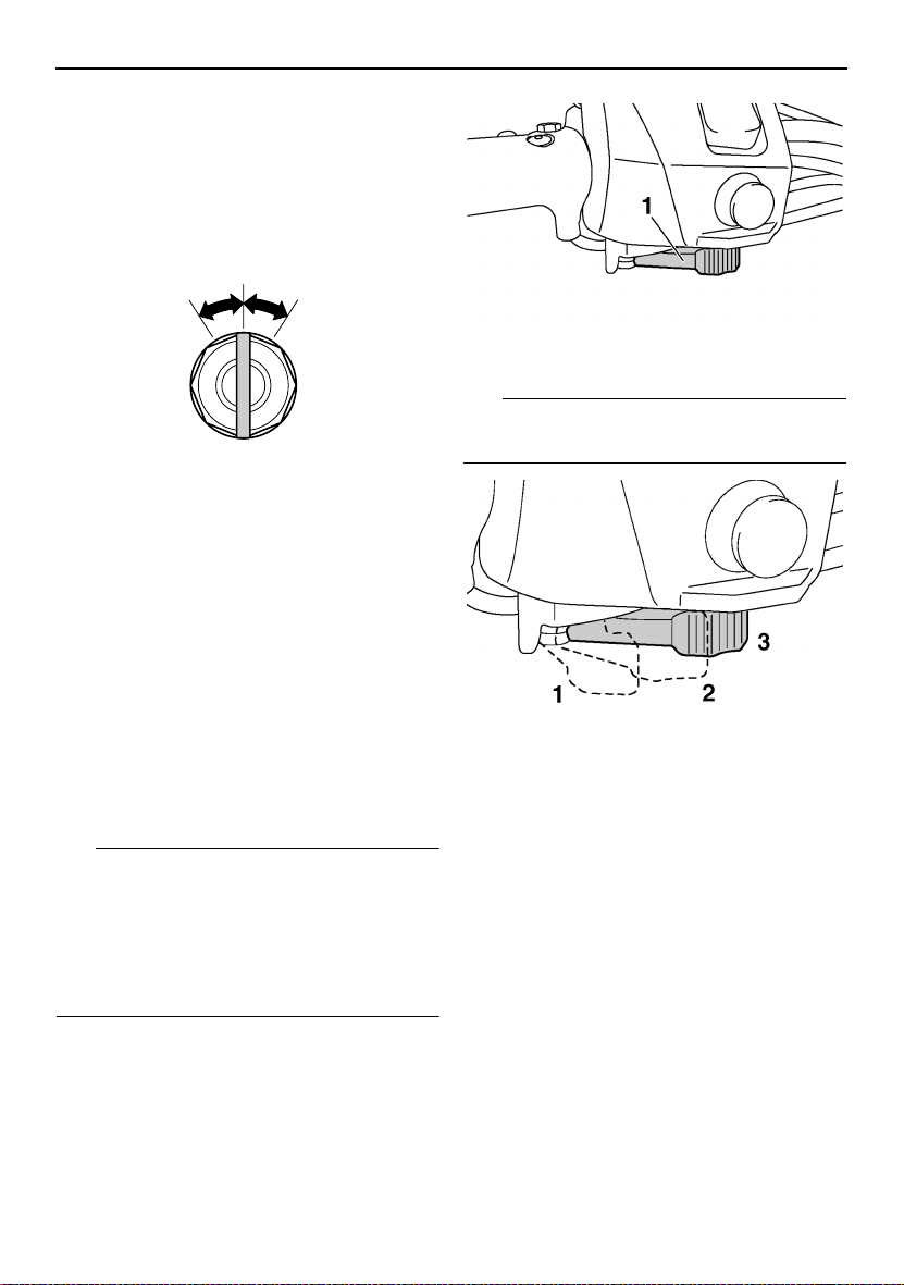
Starter (choke) lever (RST90)
Use the starter (choke) lever when starting
and warming up a cold engine.
Control functions
1. Starter (choke) lever
TIP
Refer to the “Starting the engine” section on
page 48 for proper operation.
1. When starting a cold engine.
2. Warming up
3. When the engine is warm.
ESU10312
Throttle lever
Once the engine is running cleanly, squeezing the throttle lever will increase the engine
speed and cause engagement of the drive
train. Regulate the speed of the snowmobile
by varying the throttle position. Because the
throttle is spring-loaded, the snowmobile will
decelerate, and the engine will return to idle
when it is released.
11
Control functions
1. Throttle lever
ESU13750
Throttle override system (T.O.R.S.)
EWS00041
WARNING
If the T.O.R.S. is activated, make sure that
the cause of the malfunction has been corrected and that the engine can be operated
without a problem before restarting the
engine. Continuing to operate with a malfunction could cause loss of control or
damage.
If the throttle valves or throttle cable malfunctions during operation, the T.O.R.S. will be activated when the throttle lever is released.
The T.O.R.S. is designed to override the fuel
injection (RS90GT / RS90LTGT / RST90GT)
or ignition (RST90) and limit the engine
speed to less than the clutch engagement
speed if the throttle valves fail to return to the
idle position when the throttle lever is released. (See page 122 for the clutch engagement speed.)
Malfunc-
tion
T. O. R .S .
will be ac-
tivated.
Throttle
lever
Throttle
valve
T.O. R.S.
Idling Riding
Released Squeezed Released
Closed Open Open
Engine
runs
properly.
Engine
runs
properly.
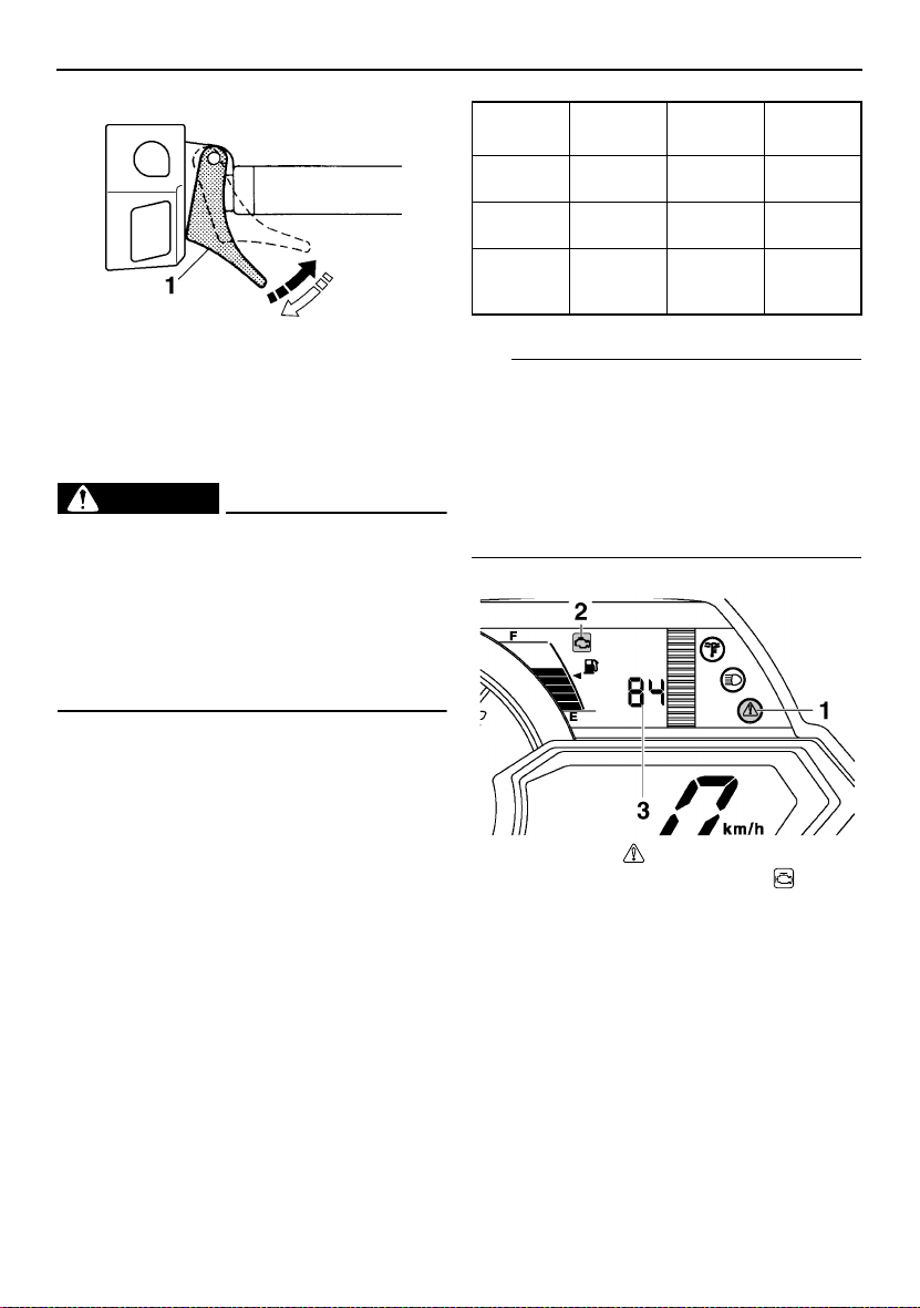
TIP
If the T.O.R.S. is activated, the warning light
and engine trouble warning indicator flash,
and the two-digit code “84” displays
(RS90GT / RS90LTGT / RST90GT) or flashes (RST90) in the meter display. If this occurs, have a Yamaha dealer check the
system as soon as possible.
RS90GT / RS90LTGT / RST90GT
1. Warning light “”
2. Engine trouble warning indicator “”
3. Two-digit code “84”
12
Control functions
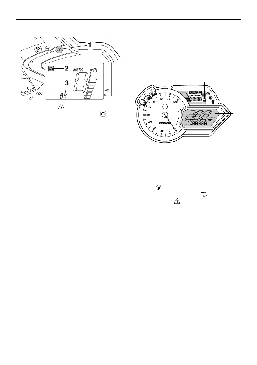
RST90
1. Warning light “”
2. Engine trouble warning indicator “”
3. Two-digit code “84”
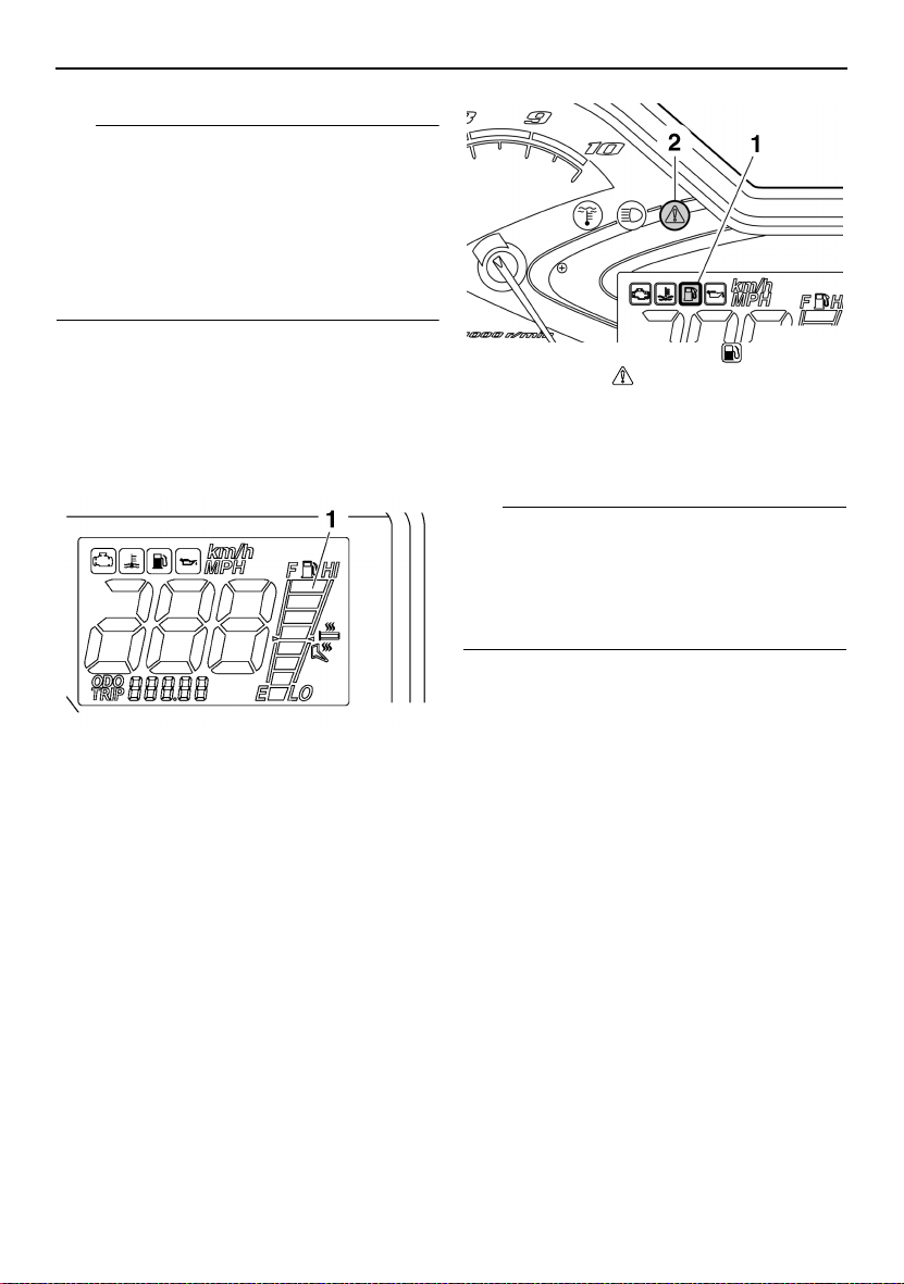
ESU14100
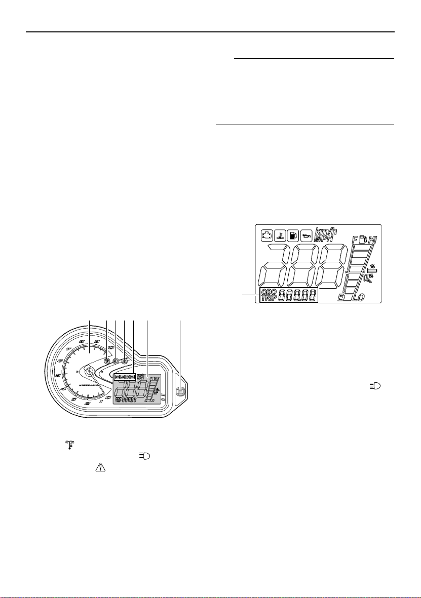
Multi-function meter unit
RS90GT / RS90LTGT / RST90GT
The multi-function meter unit is equipped with
the following:
● a digital speedometer
● a tachometer
● an odometer
● two tripmeters (which show the distance
traveled since they were last set to zero)
● a fuel reserve tripmeter (which shows the
distance traveled since the fuel level warning indicator and warning light came on)
● an oil change tripmeter (which shows the
distance traveled since the periodic oil
change interval was reached)
● a clock
● warning indicators (which show engine
trouble, coolant temperature, fuel level, and
oil level warnings)
● indicator lights (which show high beam and
low coolant temperature conditions)
● a warning light (which shows warnings to-
gether with the warning indicators)
● a fuel meter (which shows the fuel remain-
ing in the fuel tank)
● a grip/thumb warmer level indicator (which
shows the grip warmer level or the thumb
warmer level)
● a display brightness control function
When the key is turned to the on position, the
tachometer needle makes one sweep, and
the low coolant temperature indicator light,
the warning light, and all segments of the
meter unit display come on and go off.
12 3 4 5
FHI
E LO
6
7
8
9
1. “RESET” button
2. “SELECT” button
3. Tachometer
4. Warning indicators
5. Clock
6. Low coolant temperature indicator
light “”
7. High beam indicator light “”
8. Warning light “”
9. Meter display
The grip warmer level is initially displayed for
5 seconds, then the display switches to the
fuel meter.
TIP
To switch the speedometer, odometer, and
tripmeter displays between kilometers and
miles, select the odometer mode “ODO”, and
then push the “SELECT” button for at least 10
seconds while the snowmobile is stopped.
13
Control functions
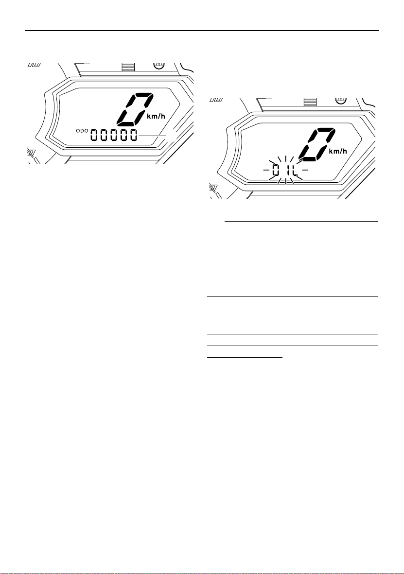
Odometer and tripmeter modes
E LO
1
1. Odometer/tripmeter/fuel reserve tripmeter
Pushing the “SELECT” button switches the
display between the odometer mode “ODO”
and the tripmeter modes “TRIP A” and “TRIP
B” in the following order:
ODO → TRIP A → TRIP B → ODO
If the fuel level warning indicator and warning
light come on (see page 18), the odometer
display will automatically change to the fuel
reserve tripmeter mode “F-TRIP” and start
counting the distance traveled from that point.
In that case, push the “SELECT” button to
switch the display between the various tripmeter and odometer modes in the following
order:
F-TRIP → ODO → TRIP A → TRIP B → FTRIP
To reset a tripmeter, select it by pushing the
“SELECT” button, and then push the “RESET” button for at least 1 second. If you do not
reset the fuel reserve tripmeter manually, it
will reset itself automatically, and the display
will return to the prior mode after the snowmobile has been refueled and traveled 5 km (3
mi).
Oil change tripmeter
When the periodic oil change interval is
reached at the initial 800 km (500 mi), then at
every 4000 km (2500 mi) thereafter, the oil
change tripmeter and “OIL” flash alternately in
the odometer display, and the tripmeter starts
counting the distance traveled from that point.
When this occurs, change the engine oil as
soon as possible. (See page 77 for the oil
change procedure.)
E LO
TIP
● The oil change tripmeter will flash only
when the snowmobile is stopped.
● To return to the previous display mode,
push the “SELECT” button. To display the
oil change tripmeter again, turn the key to
the off position, then back to the on position.
After changing the engine oil, reset the oil
change tripmeter as follows.
To reset the oil change tripmeter (when the
engine oil was changed after the oil change
tripmeter appeared)
1. To display the oil change tripmeter, turn
the key to the on position.
2. Push the “RESET” button for at least 1
second while the oil change tripmeter and
“OIL” are flashing alternately in the odometer display. The distance traveled since
the last oil change and “OIL” will flash alternately in the odometer display.
3. Push the “RESET” button for approximately 3 seconds. “00000” and “OIL” will
flash alternately in the odometer display 3
times, and then the display will return to
the previous display mode.
14
Control functions
If the engine oil is changed before the oil
change tripmeter appears in the display (i.e.,
before the periodic oil change interval has
been reached), the tripmeter must be reset after the oil change for the next periodic oil
change to be indicated at the correct time.
In that case, reset the oil change tripmeter as
follows.
To reset the oil change tripmeter (when the
engine oil was changed before the oil change
tripmeter appeared)
1. Push the “SELECT” button until “ODO” is
displayed, and then push the “RESET”
button for at least 1 second. The distance
traveled since the last oil change and
“OIL” will flash alternately in the odometer
display.
2. Push the “RESET” button for approximately 3 seconds. “00000” and “OIL” will
flash alternately in the odometer display 3
times, and then the display will return to
the previous display mode.
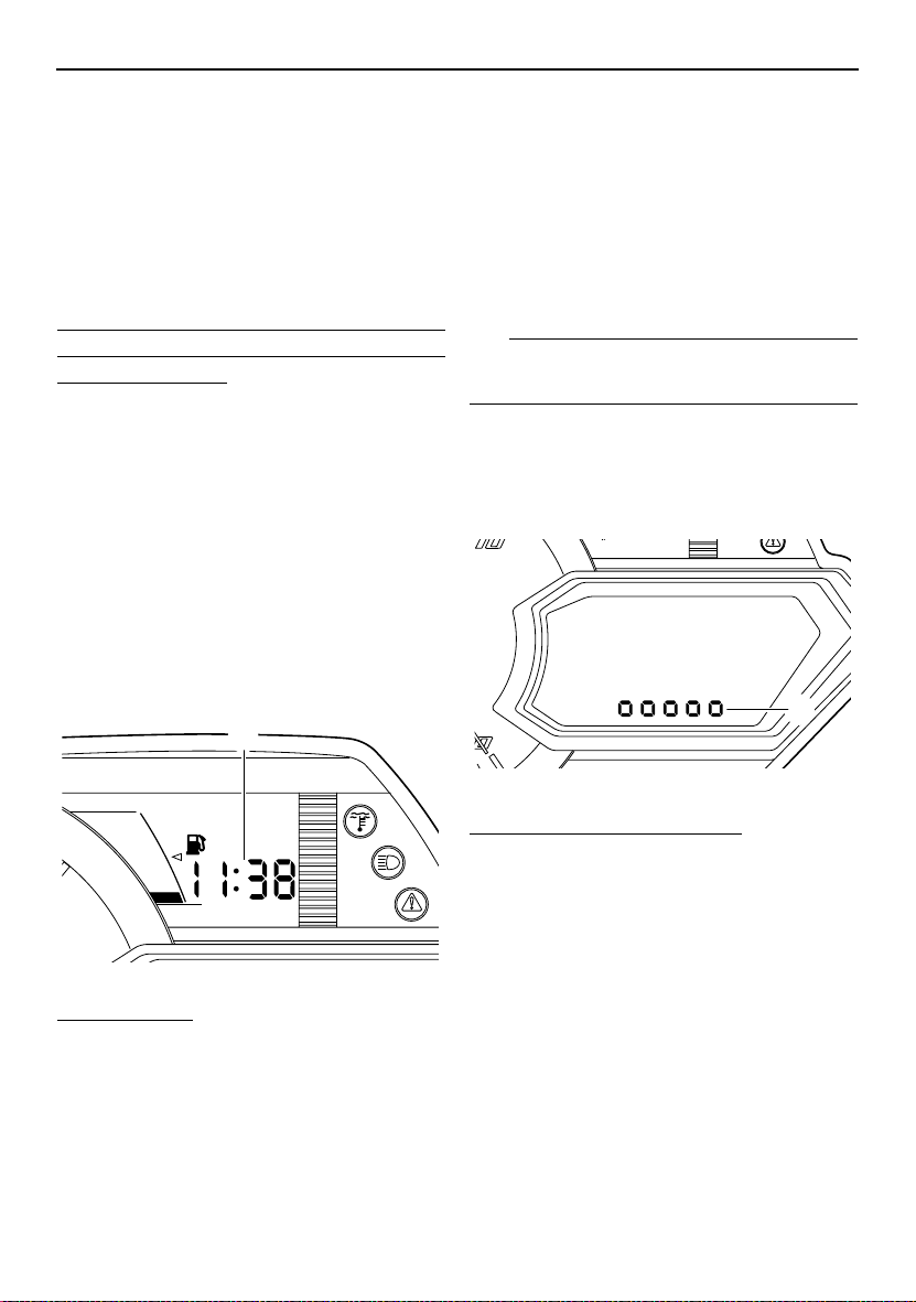
Clock
1
3. Push the “RESET” button to change the
hour setting, and then push the “SE-
LECT” button. The minute digits will start
flashing.
4. Push the “RESET” button to change the
minute setting, and then push the “SE-
LECT” button. The clock starts when the
“SELECT” button is released.
TIP
The clock must be set again when the battery
is disconnected.
Display brightness control
This function allows you to adjust the brightness of the meter unit display to suit the outdoor lighting conditions.
1
F
E
1. Clock
To set the clock
1. Turn the key to the on position.
2. Push the “SELECT” button and “RESET”
button simultaneously until the hour digits
start flashing.
1. Display brightness level
To adjust the display brightness
1. Turn the key to the off position.
2. Push and hold down the “SELECT” button.
3. Turn the key to the on position, and then,
after 5 seconds, release the “SELECT”
button.
4. Push the “RESET” button to select the
desired display brightness level, and then
push the “SELECT” button. The display
returns to the previous display mode.
RST90
The multi-function meter unit is equipped with
the following:
● a digital speedometer
15
Control functions
● a tachometer
● an odometer
● a tripmeter (which shows the distance trav-
eled since it was last set to zero)
● warning indicators (which show engine
trouble, coolant temperature, fuel level, and
oil level warnings)
● indicator lights (which show high beam and
low coolant temperature conditions)
● a warning light (which shows warnings to-
gether with the warning indicators)
● a fuel meter (which shows the fuel remain-
ing in the fuel tank)
● a grip/thumb warmer level indicator (which
shows the grip warmer level or the thumb
warmer level)
After the engine is started, the tachometer
needle makes one sweep, and the low coolant temperature indicator light, the warning
light, and all segments of the meter unit display come on and go off.
1 2 3 4 65 7
1. Tachometer
2. Low coolant temperature indicator
light “”
3. High beam indicator light “”
4. Warning light “”
5. Warning indicators
6. Meter display
7. Select/reset button
The grip warmer level is initially displayed for
5 seconds, then the display switches to the
fuel meter.
TIP
To switch the speedometer, odometer, and
tripmeter displays between kilometers and
miles, select the odometer mode “ODO”, and
then push the select/reset button for at least
10 seconds while the snowmobile is stopped.
Odometer and tripmeter modes
Pushing the select/reset button switches the
display between the odometer mode “ODO”
and the tripmeter mode “TRIP” in the following
order:
ODO → TRIP → ODO
1
1. Odometer/tripmeter
To reset the tripmeter, push the select/reset
button for at least 1 second while the tripmeter
is displayed.
ESU10411
High beam indicator light “”
The high beam indicator light comes on when
the high beams of the headlights are switched
on. (See page 23 for headlight beam switch
operation.)
16
Control functions
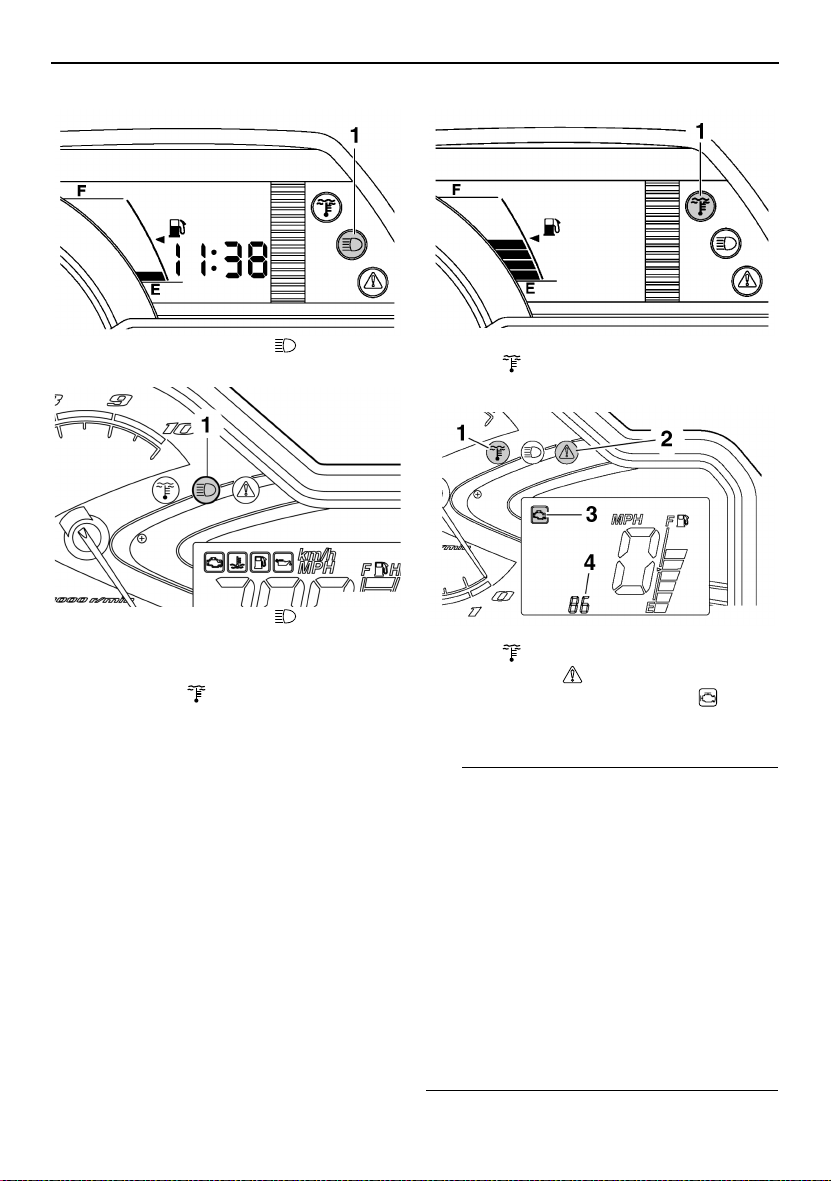
RS90GT / RS90LTGT / RST90GT
1. High beam indicator light “”
RST90
1. High beam indicator light “”
ESU13761
Low coolant temperature indicator light “”
The low coolant temperature indicator light
comes on when the coolant temperature is
low and informs the rider that the snowmobile
should be warmed up. After the engine is
started, warm it up until the indicator light
goes off.
The snowmobile can be operated normally after the indicator light goes off.
RS90GT / RS90LTGT / RST90GT
1. Low coolant temperature indicator
light “”
RST90
1. Low coolant temperature indicator
light “”
2. Warning light “”
3. Engine trouble warning indicator “”
4. Two-digit code “86”
TIP
● RS90GT / RS90LTGT / RST90GT: Drive
the snowmobile at low speeds when the low
coolant temperature indicator light is on. If
the engine speed is too high, maximum engine speed is reduced to protect the engine.
● RST90: Drive the snowmobile at low
speeds when the low coolant temperature
indicator light is on. If the engine speed is
too high, the warning light and engine trouble warning indicator flash and the two-digit
code “86” flashes in the error code display.
When this occurs, maximum engine speed
is reduced to protect the engine.
17
Control functions
ESU14040
Fuel meter and grip/thumb warmer level indicator
RS90GT / RS90LTGT / RST90GT
The fuel meter and grip/thumb warmer level
indicator have eight segments which show
the amount of fuel remaining in the fuel tank,
the grip warmer level, or the thumb warmer
level.
1. Fuel meter and grip/thumb warmer level indicator
Fuel meter
The display segments of the fuel meter disappear towards “E” (Empty) as the fuel level decreases. When only one segment is left near
“E”, the fuel level warning indicator and the
warning light come on.
TIP
The snowmobile must be stopped on a level
surface to obtain an accurate fuel meter reading, since the reading changes according to
the movement and inclination of the snowmobile.
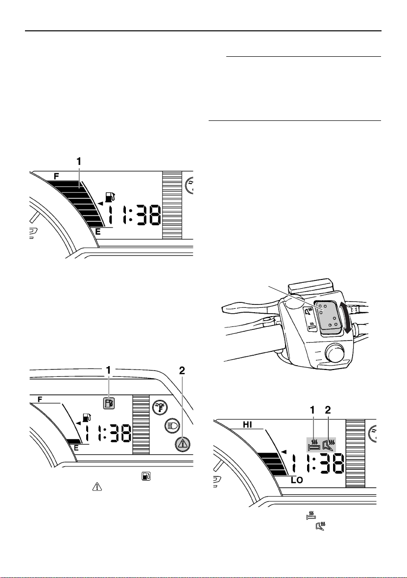
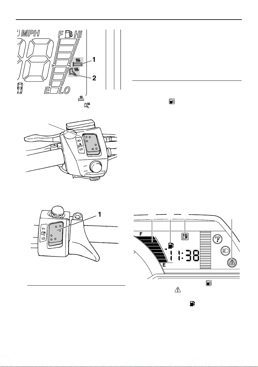
Grip/thumb warmer level indicator
When the grip warmer side of the grip/thumb
warmer adjusting switch is pressed, the grip
warmer indicator comes on and the display
switches to the grip warmer level.
When the thumb warmer side of the
grip/thumb warmer adjusting switch is
pressed, the thumb warmer indicator comes
on and the display switches to the thumb
warmer level.
See “Grip/thumb warmer adjusting switch” on
page 23 for detailed information.
1
1. Fuel level warning indicator “”
2. Warning light “”
If the fuel level warning indicator and the
warning light come on, refuel as soon as possible.
18
1. Grip/thumb warmer adjusting switch
1. Grip warmer indicator “”
2. Thumb warmer indicator “”
TIP
● The grip/thumb warmer level is displayed
for 5 seconds after releasing the grip/thumb
warmer adjusting switch, then the display
switches to the fuel meter.
● When the engine is started, the grip/thumb
warmer levels are set to the levels selected
when the engine was last stopped.
Control functions
RST90
The fuel meter and grip/thumb warmer level
indicator have eight segments which show
the amount of fuel remaining in the fuel tank,
the grip warmer level, or the thumb warmer
level.
1. Fuel meter and grip/thumb warmer level indicator
Fuel meter
The display segments of the fuel meter disappear towards “E” (Empty) as the fuel level decreases. When only one segment is left near
“E”, the fuel level warning indicator and the
warning light come on.
1. Fuel level warning indicator “”
2. Warning light “”
If the fuel level warning indicator and the
warning light come on, refuel as soon as possible.
TIP
The snowmobile must be stopped on a level
surface to obtain an accurate fuel meter reading, since the reading changes according to
the movement and inclination of the snowmobile.
Grip/thumb warmer level indicator
When the grip warmer adjusting switch is
pressed, the grip warmer indicator comes on
and the display switches to the grip warmer
level.
When the thumb warmer adjusting switch is
pressed, the thumb warmer indicator comes
on and the display switches to the thumb
warmer level.
See “Grip/thumb warmer adjusting switch” on
page 23 for detailed information.
19
Control functions
1. Grip warmer indicator “”
2. Thumb warmer indicator “”
1
1. Grip warmer adjusting switch
maximum level. The bottom segment of the
grip/thumb warmer level indicator flashes
once when the grip/thumb warmer adjustment reaches the minimum level.
● When the engine is started, the grip/thumb
warmer levels are set to the levels selected
when the engine was last stopped.
ESU13252
Fuel level warning indicator “”
The fuel level warning indicator and the warning light come on when the fuel level is low.
(See page 18 for details.)
The fuel level warning indicator, the warning
light, the fuel meter indicator (RS90GT /
RS90LTGT / RST90GT), and all segments of
the fuel meter start to flash when a malfunctioning sensor, disconnected coupler, broken
lead, or short circuit is detected by the self-diagnosis device of the snowmobile to warn the
rider of any of the above problems.
If this occurs, have a Yamaha dealer inspect
the snowmobile as soon as possible.
RS90GT / RS90LTGT / RST90GT
1. Thumb warmer adjusting switch
TIP
● The grip/thumb warmer level is displayed
for 5 seconds after releasing the grip/thumb
warmer adjusting switch, then the display
switches to the fuel meter.
● The top segment of the grip/thumb warmer
level indicator flashes once when the
grip/thumb warmer adjustment reaches the
20
31 24
1. Fuel level warning indicator “”
2. Warning light “”
3. Fuel meter
4. Fuel meter indicator “”
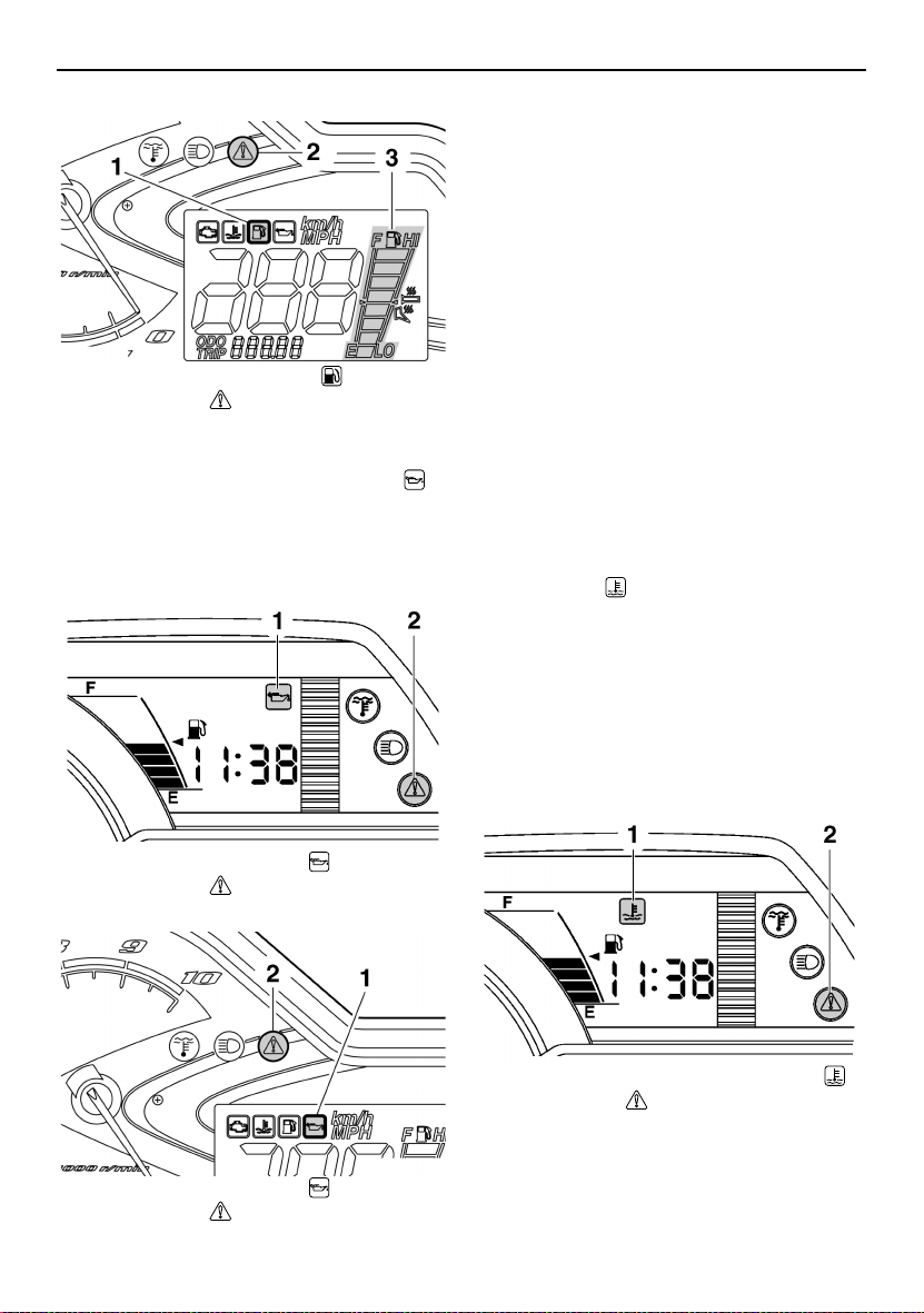
Control functions
RST90
1. Fuel level warning indicator “”
2. Warning light “”
3. Fuel meter
ESU10462
Oil level warning indicator “”
The oil level warning indicator and the warning light come on when the engine oil level is
low.
RS90GT / RS90LTGT / RST90GT
If the oil level warning indicator and the warning light come on, place the snowmobile on a
level surface and allow it to idle for one
minute.
If the oil level warning indicator and the warning light go off, the engine oil level is sufficient,
however it is getting low. Add engine oil as
soon as possible.
If the oil level warning indicator and the warning light do not go off, check the engine oil level in the oil tank (see page 77 for engine oil
level checking procedures), and add engine
oil if necessary.
If the oil level warning indicator and the warning light still remain on, have a Yamaha dealer
check the snowmobile.
ESU10513
Coolant temperature warning indicator “”
If the engine overheats, the coolant temperature warning indicator and the warning light
come on. When this occurs, stop the engine
immediately and allow the engine to cool
down, and then check the coolant level in the
coolant reservoir. (See page 83 for checking
procedures.)
RS90GT / RS90LTGT / RST90GT
1. Oil level warning indicator “”
2. Warning light “”
RST90
1. Oil level warning indicator “”
2. Warning light “”
1. Coolant temperature warning indicator “”
2. Warning light “”
21
Control functions
RST90
1. Coolant temperature warning indicator “”
2. Warning light “”
ECS00041
NOTICE
Do not continue to operate the engine if it
is overheating.
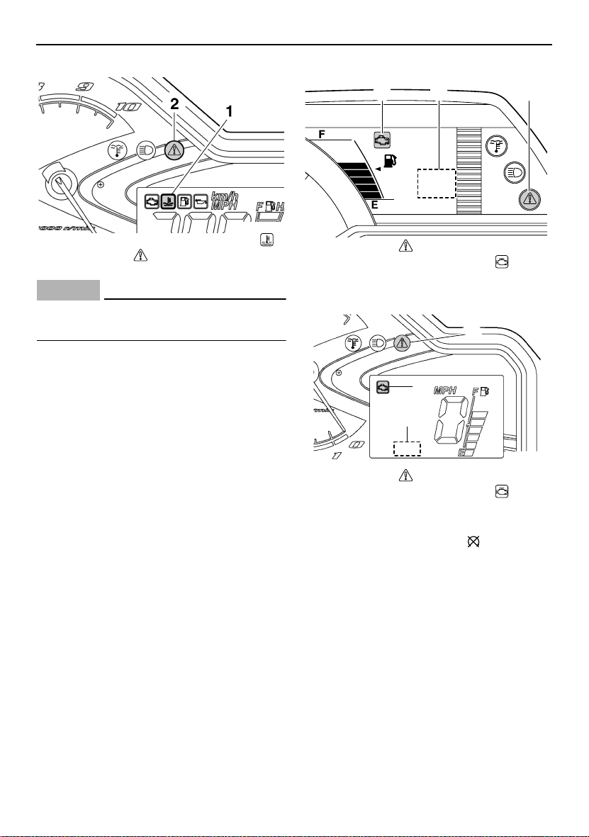
ESU13771
Self-diagnosis device
This model is equipped with a self-diagnosis
device for various electrical circuits.
If a problem is detected in any of those circuits, the warning light and the engine trouble
warning indicator flash, and an error code displays (RS90GT / RS90LTGT / RST90GT) or
flashes slowly (RST90) in the meter display.
Note the error code, and then have a Yamaha
dealer inspect the snowmobile as soon as
possible. NOTICE: Do not continue to oper-
ate the engine longer than necessary if
there is an error code to avoid possible engine damage.
[ECS00820]
RS90GT / RS90LTGT / RST90GT
312
1. Warning light “”
2. Engine trouble warning indicator “”
3. Error code display
RST90
1
2
3
1. Warning light “”
2. Engine trouble warning indicator “”
3. Error code display
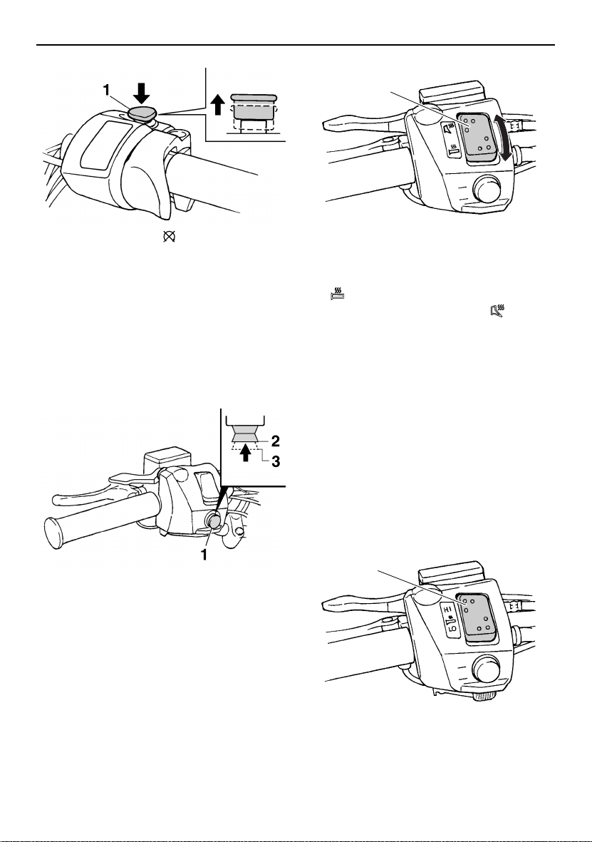
ESU10531
Engine stop switch “”
The engine stop switch is used to stop the engine in an emergency. Simply push the stop
switch to stop the engine. To start the engine,
pull the stop switch and proceed with starting
the engine. (See page 48 for engine starting
procedures.)
22
Control functions
1
1. Engine stop switch “”
During the first few rides, practice using the
stop switch so that you can react quickly in an
emergency.
ESU10661
Headlight beam switch “LIGHTS”
Push the headlight beam switch to change the
headlight to high beam “HI” or to low beam
“LO”.
1. Headlight beam switch “LIGHTS”
2. High beam “HI”
3. Low beam “LO”
ESU14061
Grip/thumb warmer adjusting switch
RS90GT / RS90LTGT / RST90GT
The grip/thumb warmer adjusting switch controls the electrically heated handlebar grips
and throttle lever.
1. Grip/thumb warmer adjusting switch
To raise the temperature
To raise the grip warmer temperature, press
the “” side of the switch. To raise the thumb
warmer temperature, press the “” side of
the switch.
To lower the temperature
Continue to press the switch until the temperature level returns to the minimum level, and
then raise the temperature to the desired level.
See “Fuel meter and grip/thumb warmer level
indicator” on page 18 for detailed information.
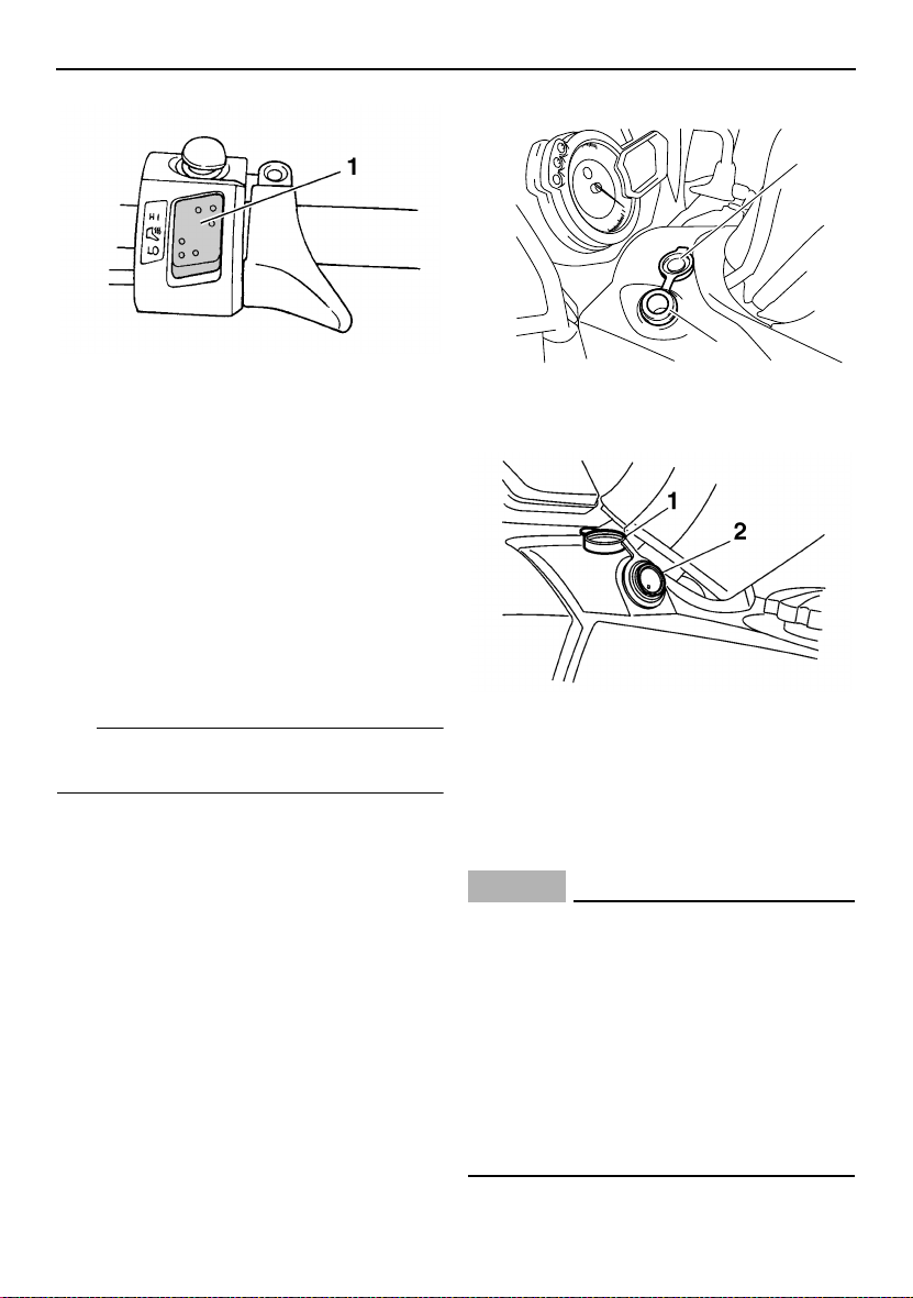
RST90
The grip warmer adjusting switch and the
thumb warmer adjusting switch control the
electrically heated handlebar grips and throttle lever respectively.
1
1. Grip warmer adjusting switch
23
Control functions
RS90GT / RS90LTGT / RST90GT
1
1. Thumb warmer adjusting switch
To raise the temperature
To raise the temperature, press the respective switch to “HI”.
To lower the temperature
To lower the temperature, press the respective switch to “LO”.
See “Fuel meter and grip/thumb warmer level
indicator” on page 18 for detailed information.
ESU10696
Auxiliary DC jack
The auxiliary DC jack is located in the front
panel and can be used for accessories.
TIP
The auxiliary DC jack can only be used if the
engine is running.
To use the auxiliary DC jack
1. Start the engine.
2. Open the auxiliary DC jack cap, and then
insert the accessory power plug into the
jack.
2
1. Auxiliary DC jack cap
2. Auxiliary DC jack
RST90
1. Auxiliary DC jack cap
2. Auxiliary DC jack
3. After using the auxiliary DC jack, be sure
to remove the accessory power plug from
the jack and to close the auxiliary DC jack
cap.
ECS00122
NOTICE
● To avoid circuit overload and a possible
fuse blowing, do not use accessories requiring more than the maximum rated
capacity for the auxiliary DC jack. (See
page 109 for the specified fuse amperage.)
● Do not use an automotive cigarette light-
er or other accessory with a plug that
gets hot because the jack can be damaged.
24
 Loading...