

Page 1
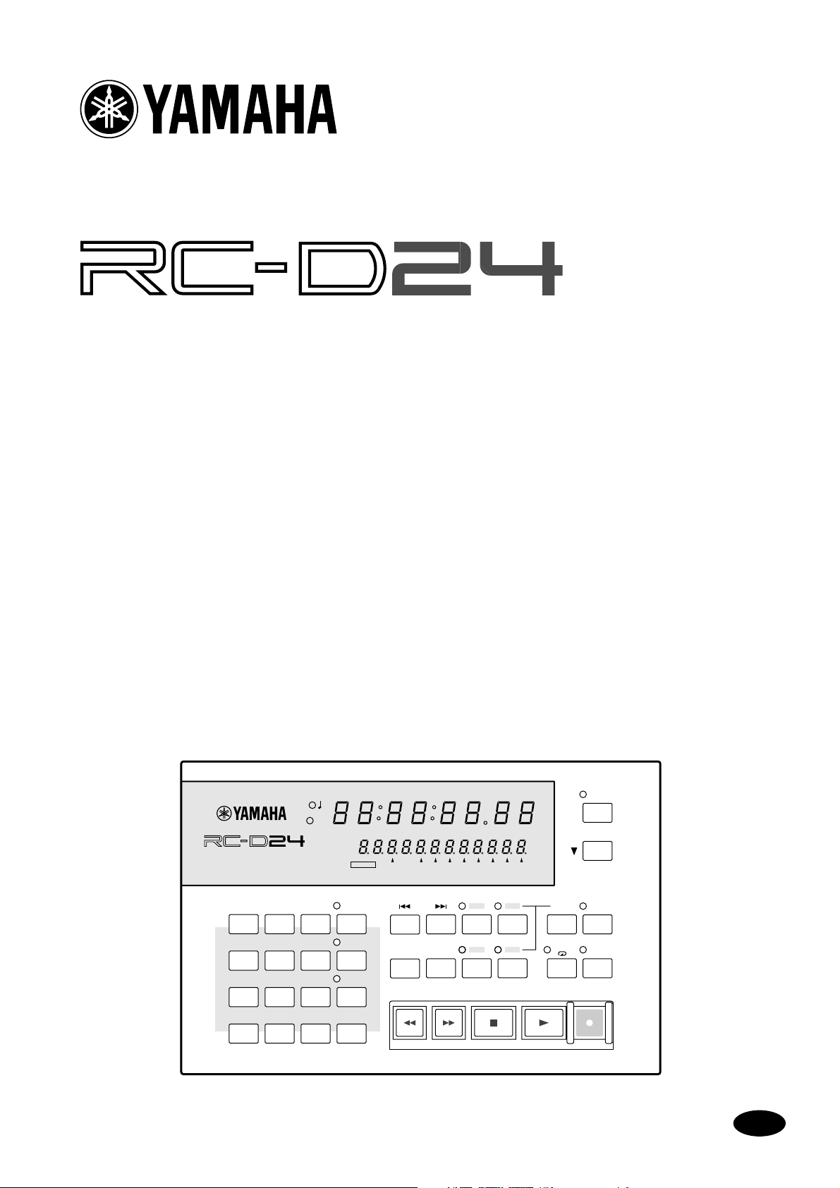
REMOTE CONTROLLER/LOCATOR
Owner’s Manual
Mode d’emploi
Bedienungsanleitung
Manual de instrucciones
取扱説明書
REMOTE CONTROLLER/LOCATOR
7
8
4
5
1
2
0
SET
REPEAT
A B
ABS
CAPTURE
UNIT SELECT
AUTO
PUNCH
REHE
FSMH
ms
READY
PROJECT
9
SELECT
LOC MEM
6
RECALL
LOC MEM
3
STORE
LOCATEENTERCANCEL
H
PROJECT SEARCH
ROLL
RTN TO
BACK
ZERO
REW FF STOP PLAY REC
SFmsM
LAST REC
IN
A
81UNIT 234567
OUT
B
M
Page 2

FCC INFORMATION (U.S.A.)
1. IMPORTANT NOTICE: DO NOT MODIFY THIS UNIT! This product, when installed as indicated in the instructions contained in this manual, meets FCC
requirements. Modifications not expressly approved by Yamaha may void your authority, granted by the FCC, to use the product.
2. IMPORTANT: When connecting this product to accessories and/or another product use only high quality shielded cables. Cable/s supplied with this product MUST
be used. Follow all installation instructions. Failure to follow instructions could void your FCC authorization to use this product in the USA.
3. NOTE: This product has been tested and found to comply with the requirements listed in FCC Regulations, Part 15 for Class “B” digital devices. Compliance with
these requirements provides a reasonable level of assurance that your use of this product in a residential environment will not result in harmful interference with
other electronic devices. This equipment generates/uses radio frequencies and, if not installed and used according to the instructions found in the users manual, may
cause interference harmful to the operation of other electronic devices. Compliance with FCC regulations does not guarantee that interference will not occur in all
installations. If this product is found to be the source of interference, which can be determined by turning the unit “OFF” and “ON”, please try to eliminate the
problem by using one of the following measures: Relocate either this product or the device that is being affected by the interference. Utilize power outlets that are on
different branch (circuit breaker or fuse) circuits or install AC line filter/s. In the case of radio or TV interference, relocate/reorient the antenna. If the antenna lead-in
is 300 ohm ribbon lead, change the lead-in to coaxial type cable. If these corrective measures do not produce satisfactory results, please contact the local retailer
authorized to distribute this type of product. If you can not locate the appropriate retailer, please contact Yamaha Corporation of America, Electronic Service
Division, 6600 Orangethorpe Ave, Buena Park, CA 90620
The above statements apply ONLY to those products distributed by Yamaha Corporation of America or its subsidiaries.
Page 3

i
Contents
Welcome to the RC-D24 . . . . . . . . . . . . . . 1
About this Owner’s Manual . . . . . . . . . . . 1
RC-D24 Operating Notes . . . . . . . . . . . . . 1
Touring the RC-D24 . . . . . . . . . . . . . . . . . 2
Connecting the RC-D24 . . . . . . . . . . . . . . 7
Selecting D24s in Multiple-Unit Systems . 8
Selecting Tracks for Recording . . . . . . . . . 9
Checking the Version Number . . . . . . . . . 9
Updating the System Software . . . . . . . . . 9
Specifications . . . . . . . . . . . . . . . . . . . . . . 10
Important Information
Read the Following Before Using the RC-D24 Remote
Controller/Locator
• Do not subject the RC-D24 to extreme temperatures, humidity, direct sunlight, or dust,
which could be a potential fire or electrical
shock hazard.
• Do not place heavy objects on the remote
cable.
• If the remote cable is damaged (e.g., cut or a
bare wire is exposed), ask your dealer for a
replacement.
• Do not place small metal objects on top of the
RC-D24. A metal object falling inside the
RC-D24 is a fire and electrical shock hazard.
Interference
The RC-D24 uses high-frequency digital circuits
that may cause interference on radio and television equipment located nearby. If interference is a
problem, relocate the affected equipment.
RC-D24 Exclusion of Certain
Responsibility
Manufacturer, importer, or dealer shall not be liable for any incidental damages including personal
injury or any other damages caused by improper
use or operation of the RC-D24.
• If you notice any abnormality—such as smoke,
odor, or noise—turn off the RC-D24 immediately and disconnect it from the D24. Confirm
that the abnormality is no longer present.
Using the RC-D24 in this condition is a potential fire and shock hazard. Consult your dealer
for repair.
• If a foreign object or water gets inside the
RC-D24, turn it off immediately and disconnect it from the D24. Using the RC-D24 in this
condition is a potential fire and electrical
shock hazard. Consult your dealer for repair.
• Do not attempt to modify the RC-D24. This is
a potential fire and electrical shock hazard.
• The RC-D24 operating temperature is
between 5˚C and 35˚C (41˚F and 95˚F).
• Do not use benzene, thinner, cleaning detergent, or a chemical cloth to clean the RC-D24.
Use only a soft, dry cloth.
Package Contents
The RC-D24 package should contain the following items. Contact your Yamaha dealer if you are
missing an item.
• RC-D24 Remote Controller/Locator
• Remote cable
• This manual
Trademarks
Yamaha is a trademark of Yamaha Corporation.
All other trademarks are the property of their
respective holders and are hereby acknowledged.
Copyright
No part of the RC-D24 software or this Owner’s
Manual may be reproduced or distributed in any
form or by any means without the prior written
authorization of Yamaha Corporation.
© 1999 Yamaha Corporation. All rights reserved.
Keep This Manual For Future Reference!
RC-D24—Owner’s Manual
Page 4

1
Welcome to the RC-D24
Welcome to the RC-D24
Thank you for choosing the Yamaha RC-D24 Remote Controller/Locator. The RC-D24
is for exclusive use with the Yamaha D24 Digital Multitrack Recorder.
About this Owner’s Manual
Since most of the RC-D24 functions operate the same as on the D24, this Owner’s Man-
ual
does not contain detailed explanations for each function. Refer to the
Manual
for detailed information.
RC-D24 Operating Notes
The RC-D24 draws its power from the connected D24 and can be turned on or off
either before or after the D24.
If the RC-D24 is off, but the connescted D24 is on for normal poeration, there’s a possibility that noise from the remote cable may cause the D24 to malfunction. To prevent
this, disconnect the RC-D24 from the D24, or turn on the RC-D24.
D24 Owner’s
In a multiple-unit system, the RC-D24 can control the entire system through Chase
mode or individual D24s. See “Selecting D24s in Multiple-Unit Systems” on page 8 for
more information.
Unlike the D24, which has two lines in the message area of the display, the RC-D24 display has just one line, which more or less corresponds to the 2nd line of the D24 display.
On the RC-D24, tracks are selected for recording using the keypad number buttons. See
“Selecting Tracks for Recording” on page 9 for more information.
The RC-D24 does not have a JOG/DATA dial, so although it can be used for auto punch
in/out recording, the Audition Take and Fix Take functions cannot be controlled
remotely. Use the D24 controls when you want to use these functions.
RC-D24—Owner’s Manual
Page 5

Touring the RC-D24
Touring the RC-D24
This section tours around the RC-D24’s control surface and rear panel, explaining the
purpose of each control and connector.
Control Surface
SET
REPEAT
A B
ABS
CAPTURE
UNIT SELECT
AUTO
PUNCH
REHE
REMOTE CONTROLLER/LOCATOR
7
8
4
5
1
2
0
ms
00 00 00 00
READY
PROJECT
9
SELECT
LOC MEM
6
RECALL
LOC MEM
3
STORE
LOCATEENTERCANCEL
H
PROJECT SEARCH
ROLL
RTN TO
BACK
ZERO
REW FF STOP PLAY REC
SFmsM
LAST REC
IN
A
FSMH
81UNIT 234567
OUT
B
2
The RC-D24 control surface is explained in the following sections.
Display
21 3
ms
00 00 00 00
H
REMOTE CONTROLLER/LOCATOR
0 0 0 0 0 0 0 0 0 0 0 0
READY
4
A
ms indicator
This indicator lights up when the D24 counter is set to display milliseconds instead of
sub-frames. This indicator works only if supported by the D24 system software.
SFmsM
FSMH
81UNIT 234567
RC-D24—Owner’s Manual
Page 6
3
Touring the RC-D24
Quarter-note indicator
B
This indicator lights up when the D24 is set to display MIDI Clock information instead
of SMPTE/EBU timecode. This indicator works only if supported by the D24 system
software.
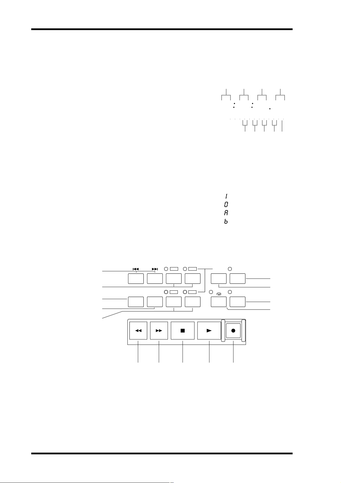
Counter
C
The counter shows the current position in hours,
minutes, seconds, and frames (00:00:00.00).
D
Message area
The message area of the display more or less corresponds to the 2nd line of the D24’s
display, and shows captured positions, locate point positions, project numbers, locate
memory numbers, take numbers, remote unit IDs, and tracks selected for recording.
Time information is displayed in hours, minutes, seconds, frames, and sub-frames
(00:00:00.00.0).
Hour Min Sec fr
00 0000 00
H
SFmsM
0 0 0 0 0 0 0 0 0 0 0 0
Hour Min Sec fr sub-fr
FSMH
LAST REC IN, LAST REC OUT, A, and B point values are identified using the prefixes shown here.
Transport Controls
5
4
3
2
1
PROJECT SEARCH
RTN TO
ZERO
ROLL
BACK
REW FF STOP PLAY REC
LAST REC
IN
A
OUT
B
— LAST REC IN point
— LAST REC OUT point
— A point
— B point
SET
REPEAT
A B
AUTO
PUNCH
REHE
6
7
8
9
A
B
RC-D24—Owner’s Manual
J K L M N
A & B buttons & indicators
These buttons are used to set and locate the A and B points. The A and B indicators light
up when the respective A or B point is set.
ROLL BACK button
This button is used to roll back from the current position in steps of between 1 and 30
seconds, the default being 5 seconds.
Page 7

Touring the RC-D24
RTN TO ZERO button
C
This button is used to locate the zero position.
LAST REC IN & OUT buttons & indicators
D
These buttons are used to set and locate the LAST REC IN and LAST REC OUT points.
The IN and OUT indicators light up when the respective IN or OUT point is set.
PROJECT SEARCH buttons
E
These buttons are used to search for projects. Pressing the [ ] button selects the top
of the current project. Pressing the [ ] button selects the top of the next project.
F
AUTO PUNCH button & indicator
This button selects the Auto-Punch In/Out function. The AUTO PUNCH indicator
flashes when this function is on.
SET button
G
This button is used in conjunction with the LAST REC [IN], LAST REC [OUT], [A],
and [B] buttons to set the LAST REC IN, LAST REC OUT, A, and B points, respectively.
It’s also used in conjunction with the [RTN TO ZERO] button to set the relative zero
position.
The [SET] button is also used in conjunction with the [ENTER] button for the Auto
Locate Memory Store function, and in conjunction with the [LOCATE] button to set
the Keypad Timecode Input mode.
4
REHE button & indicator
H
This button is used to engage Rehearsal Standby mode and, when pressed together with
the [PLAY] button, punch in rehearsal. In Rehearsal mode, recording can be practiced,
with automatic playback and input monitor switching at the punch in and out points,
without actually recording anything to disk. The REHE button indicator flashes in
Rehearsal Standby mode, and lights up continuously during rehearsal.
I
REPEAT button & indicator
This button selects the A–B Repeat playback function. The REPEAT indicator lights up
when this function is on.
REW button
J
This button is used to start rewind. Press it once for rewind at 8x normal play speed, the
REW button indicator flashes. Press it again for rewind at 16x normal play speed, the
REW button indicator lights up continuously. Pressing and holding the REW button
during playback rewinds at 8x normal play speed.
FF button
K
This button is used to start fast forward. Press it once for fast forward at 8x normal play
speed, the FF button indicator flashes. Press it again for fast forward at 16x normal play
speed, the FF button indicator lights up continuously. Pressing and holding the FF button during playback fast forwards at 8x normal play speed.
STOP button
L
This button is used to stop playback, recording, rehearsal, rewind, and fast forward, and
to cancel Rehearse Standby mode. The STOP button indicator lights up when the D24
is stopped.
M
PLAY button
This button is used to start playback, punch out of recording or rehearsal, and in conjunction with the [REC] and [REHE] buttons, punch in for recording or rehearsal,
respectively. The PLAY button indicator lights up during playback, recording, and
rehearsal.
RC-D24—Owner’s Manual
Page 8

5
Touring the RC-D24
REC button
N
This button is used in conjunction with the [PLAY] button to start recording. The REC
button indicator lights up while recording.
Other Buttons
O
ABS button & indicator
This button is used to set the counter mode to either Absolute (ABS), the default setting, or Relative (REL). The ABS indicator lights up when Absolute (ABS) is selected.
ABS
O
CAPTURE
P
UNIT SELECT
P
CAPTURE/UNIT SELECT button
This button has two functions: Capture and Unit Select. Pressed on its own, it’s used to
capture time positions while the D24 is stopped or during rewind, fast forward, playback, recording, or rehearsal. Captured values can be located or stored in locate memories. Pressed in conjunction with the [SET] button, it’s used to access the Unit Select
function, which is used to select individual D24s in multiple-unit systems. See “Selecting D24s in Multiple-Unit Systems” on page 8 for more information.
Keypad
PROJECT
9
SELECT
2
LOC MEM
6
RECALL
3
LOC MEM
3
STORE
4
LOCATEENTERCANCEL
5
1
7
4
1
0
8
5
2
A
RC-D24—Owner’s Manual
76
Keypad buttons
The keypad is used with various functions to enter time values, parameter values,
project numbers, locate memory numbers, select tracks for recording, select individual
D24s in multiple-unit systems, and so on.
Page 9

Touring the RC-D24
PROJECT SELECT button & indicator
B
This button is used to select projects by number. The PROJECT SELECT indicator
lights up when the Project Select function is on.
LOC MEM RECALL button & indicator
C
This button is used to recall locate memories. The LOC MEM RECALL indicator lights
up when the Locate Memory Recall function is on.
LOC MEM STORE button & indicator
D
This button is used to store locate memories. The LOC MEM STORE indicator lights
up when the Locate Memory Store function is on.
LOCATE button
E
This button is used to locate positions.
CANCEL button
F
This button is used to cancel functions and reset time values to zero.
ENTER button
G
This button is used to select, confirm, and execute functions.
6
Rear Panel
POWER
ON OFF
1
POWER switch
A
This switch is used to turn on and off the RC-D24. Since the RC-D24 receives its power
via the remote cable and connected D24, the RC-D24 can only be turned on when the
D24 to which it is connected is turned on.
B
REMOTE connector
This 15-pin D-sub connector is used to connect the RC-D24 to the REMOTE IN/SYNC
IN connector on the D24, using the supplied remote cable.
REMOTE
2
RC-D24—Owner’s Manual
Page 10
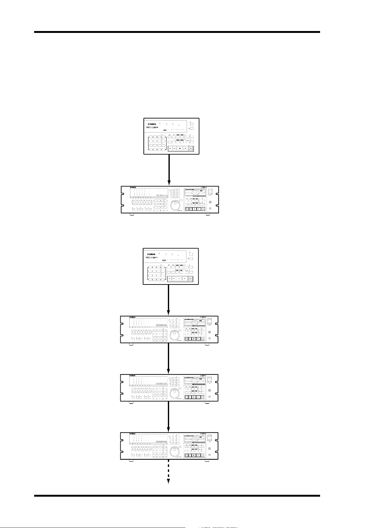
7 Connecting the RC-D24
Connecting the RC-D24
The REMOTE connector on the RC-D24 should be connected to the REMOTE
IN/SYNC IN connector on the D24 using the supplied remote cable. In a multiple-unit
system, the RC-D24 should be connected to the master D24.
Connecting to a Single D24
RC-D24
ms
00 0000 00
REMOTE CONTROLLER/LOCATOR
7
8
9
4
5
6
2
1
3
0
Remote cable
H
READY
PROJECT SEARCH
PROJECT
SELECT
LOC MEM
RECALL
RTN TO
ZERO
LOC MEM
STORE
REW FF STOP PLAY REC
LOCATEENTERCANCEL
FSMH
SFmsM
81UNIT 234567
LAST REC
SET
OUT
IN
REPEAT
ROLL
A
B
BACK
A B
REMOTE
UNIT SELECT
ABS
CAPTURE
AUTO
PUNCH
REHE
Unit Select: 1
D24
OVER
0
–dB
2
6
1012
1420
1830
20
42
2660
READY
RECORD
READY
SOLO/
SELECT
OVER
0
–dB
2
6
12
20
30
42
60
READY
R
L
8
7654321
PEAK
AUTO
ALL
FORMAT CHASE
HOLD
INPUT
INPUT
MONITOR SELECT
REMOTE IN/SYNC IN
TIME DISPLAY
CAPTURE ABS/REL
ABS H
MSF
00 00 00 00
VARI
UTILITY
YAMAHA D24
SPEED
LOCK
INT2448K
WC
BITFSTC
7
4
1
0/-
UNDO/
V. TRACK
EDIT
SELECT
REDO
MASTER
PROJECT
8
9
SELECT
LOC MEM
5
6
RECALL
LOC MEM
2
3
STORE
LOCATEENTERCANCEL
JOG/DATA SHUTTLE/
DIGITAL MULTITRACK RECORDER
REMAIN
SETUP
PROJECT SEARCH
LAST REC
SET
OUT
IN
JOG ON
RTN TO
ROLL
REPEAT
A
B
ZERO
BACK
BA
STOP PLAY REC
REW FF
CURSOR
Connecting to Multiple D24s
RC-D24
ABS
REMOTE CONTROLLER/LOCATOR
7
8
9
5
6
4
2
3
1
0
Remote cable
D24-A (master)
AUTO
INPUT
MONITOR SELECT
ABS H
OVER
0
–dB
00 00 00 00
2
6
YAMAHA D24
12
20
30
42
INT2448K
WC
LOCK
60
READY
BITFSTC
R
L
8
7
8
7654321
4
5
1
2
ALL
FORMAT CHASE
INPUT
0/-
OVER
0
–dB
2
6
1012
1420
1830
20
42
2660
READY
RECORD
READY
SOLO/
SELECT
PEAK
HOLD
15-pin sync cable
ms
00 0000 00
READY
PROJECT
SELECT
LOC MEM
RECALL
LOC MEM
STORE
LOCATEENTERCANCEL
MSF
MASTER
PROJECT
9
SELECT
LOC MEM
6
RECALL
LOC MEM
3
STORE
LOCATEENTERCANCEL
FSMH
SFmsM
H
CAPTURE
81UNIT 234567
PROJECT SEARCH
RTN TO
ZERO
REW FF STOP PLAY REC
UNIT SELECT
LAST REC
AUTO
SET
OUT
IN
PUNCH
REPEAT
ROLL
REHE
A
B
BACK
A B
REMOTE
REMOTE IN/SYNC IN
TIME DISPLAY
CAPTURE ABS/REL
VARI
SPEED
V. TRACK
SELECT
DIGITAL MULTITRACK RECORDER
REMAIN
UTILITY
SETUP
UNDO/
EDIT
REDO
LAST REC
PROJECT SEARCH
AUTO
SET
OUT
IN
PUNCH
ROLL
RTN TO
REPEAT
REHE
A
B
BACK
ZERO
BA
STOP PLAY REC
REW FF
JOG/DATA SHUTTLE/
JOG ON
CURSOR
SYNC OUT
POWER
ON
OFF
AUTO
PUNCH
REHE
WC: INT, TC: MASTER/30 fps
Chase: Off
010
PHONES
LEVEL
Remote ID: 1
PHONES
Unit Select: 1
POWER
WC: INT
ON
OFF
TC: MASTER/30 fps
010
PHONES
LEVEL
Chase: Off
PHONES
Remote ID: 1
RC-D24—Owner’s Manual
D24-B (slave)
OVER
0
–dB
2
6
1012
1420
1830
20
42
2660
READY
RECORD
READY
SOLO/
SELECT
15-pin sync cable
OVER
0
–dB
2
6
12
20
30
42
60
READY
R
L
8
7654321
PEAK
AUTO
ALL
FORMAT CHASE
HOLD
INPUT
INPUT
MONITOR SELECT
D24-C (slave)
OVER
0
–dB
2
6
1012
1420
1830
20
42
2660
READY
RECORD
READY
SOLO/
SELECT
OVER
0
–dB
2
6
12
20
30
42
60
READY
R
L
8
7654321
PEAK
AUTO
ALL
FORMAT CHASE
HOLD
INPUT
INPUT
MONITOR SELECT
REMOTE IN/SYNC IN
TIME DISPLAY
CAPTURE ABS/REL
8
5
2
MSF
MASTER
PROJECT
9
SELECT
LOC MEM
6
RECALL
LOC MEM
3
STORE
LOCATEENTERCANCEL
REMAIN
VARI
UTILITY
SETUP
SPEED
UNDO/
V. TRACK
EDIT
SELECT
REDO
JOG/DATA SHUTTLE/
ABS H
00 00 00 00
YAMAHA D24
LOCK
INT2448K
WC
BITFSTC
7
4
1
0/-
SYNC OUT
REMOTE IN/SYNC IN
TIME DISPLAY
CAPTURE ABS/REL
8
5
2
MSF
MASTER
PROJECT
9
SELECT
LOC MEM
6
RECALL
LOC MEM
3
STORE
LOCATEENTERCANCEL
REMAIN
VARI
UTILITY
SETUP
SPEED
UNDO/
V. TRACK
EDIT
SELECT
REDO
JOG/DATA SHUTTLE/
ABS H
00 00 00 00
YAMAHA D24
INT2448K
WC
LOCK
BITFSTC
7
4
1
0/-
SYNC OUT
Next D24
DIGITAL MULTITRACK RECORDER
POWER
TC: REMOTE IN/30 fps
OFF
LAST REC
IN
A
STOP PLAY REC
DIGITAL MULTITRACK RECORDER
LAST REC
IN
A
STOP PLAY REC
ON
AUTO
SET
OUT
PUNCH
REPEAT
REHE
B
BA
AUTO
SET
OUT
PUNCH
REPEAT
REHE
B
BA
Chase: On
010
PHONES
LEVEL
Remote ID: 2
PHONES
POWER
TC: REMOTE IN/30 fps
OFF
ON
Chase: On
010
PHONES
LEVEL
Remote ID: 3
PHONES
PROJECT SEARCH
JOG ON
RTN TO
ROLL
ZERO
BACK
REW FF
CURSOR
PROJECT SEARCH
JOG ON
RTN TO
ROLL
ZERO
BACK
REW FF
CURSOR
Page 11

Selecting D24s in Multiple-Unit Systems 8
Selecting D24s in Multiple-Unit Systems
In a multiple-unit system, the RC-D24 can control the entire system through Chase
mode or individual D24s. To control the entire system through Chase mode, the Unit
Select function is set to the same ID as that assigned to the master D24. Individual D24s
can be controlled using the exclusive Remote ID number assigned to each D24. (See the
D24’s Owner’s Manual for more information on setting Remote IDs.) To control the
D24 assigned Remote ID 2, for example, the Unit Select function on the RC-D24 is set
to ID 2.
1 While holding down the [SET] button, press the [UNIT SELECT] button.
The current Unit Select setting flashes on the display, as shown below. The small circles
above the unit numbers indicate which D24s are available.
ms
00 00 00 00
H
SFmsM
FSMH
REMOTE CONTROLLER/LOCATOR
READY
Current Unit
Select setting
1
81UNIT 234567
Available D24s
If a D24 doesn’t appear to be available, make sure that it’s connected correctly and
turned on. See page 7 for more information on connecting the RC-D24 and D24s.
2 Use keypad buttons [1] through [8] to select individual D24s.
3 Press the [ENTER] button to activate your selection, or the [CANCEL] button
to leave the Unit Select function.
The small circles above the unit numbers disappear and the previously shown information reappears on the display.
RC-D24—Owner’s Manual
Page 12

9 Selecting Tracks for Recording
Selecting Tracks for Recording
The RC-D24 does not have dedicated RECORD READY buttons like the D24. Instead
tracks are selected for recording using the [REC] button and keypad buttons [1]
through [8].
1 While holding down the [REC] button, use keypad buttons [1] through [8] to
select tracks for recording.
When a track is selected for recording, a small circle appears above the corresponding
track number, as shown below, and the corresponding READY indicator flashes on the
D24. The Unit Select setting is displayed on the RC-D24 while the [REC] button is
pressed, as shown below.
All tracks can be selected for recording by pressing the [0] button while holding down
the [REC] button, and all tracks can deselected by pressing the [9] button while holding
down the [REC] button.
ms
00 00 00 00
H
SFmsM
FSMH
REMOTE CONTROLLER/LOCATOR
READY
Current Unit
Select setting
2 Release the [REC] button when you’ve selected tracks for recording.
1
Tracks selected
for recording
The Unit Select setting can be changed simply by pressing the [UNIT SELECT] button
while holding down the [REC] button, allowing you to select tracks on other D24s.
Recording is started in the normal way, see the D24 Owner’s Manual for more informa-
tion.
Checking the Version Number
You can check the version number of the RC-D24 system software as follows.
1 Turn off the RC-D24.
2 While holding down the [RTN TO ZERO] button, turn on the RC-D24.
81UNIT 234567
Updating the System Software
RC-D24—Owner’s Manual
The version number appears on the display.
See the Yamaha Professional Audio Web site at the address below for information on
system updates.
<http://www.yamaha.co.jp/product/proaudio/homeenglish/>
Page 13

Specifications
Specifications 10
Repeat playback
Punch in/out
Auto Punch multi-take recording
Project Select/Search
Locate point set/search
Locate
Display
Others
Locate memory store/recall
Return to zero
Roll back
Counter
Message area
ABS/REL
CAPTURE
POWER SW
A–B Repeat
Auto, Manual, Rehearsal
Up to 99 takes
LAST REC IN, LAST REC OUT, A, B
99
7-segment LED x 8
Time display: Hours, minutes, seconds, frames
7-segment LED x 12
Time display: Hours, minutes, seconds, frames,
sub-frames
15-pin D-sub connector
Mounting
screws
Supply voltage
Power consumption
Dimensions (W
Weight
Free-air operating temperature range
Relative humidity
Accessories
Speaker bolts
Mic stand
×
H × D)
Specifications subject to change without notice.
M5 nut x 2
W3/8
12 V DC
10 W
214 × 50 × 138 mm (8.4 x 2 x 5.4 inches)
1 kg (2.2 lbs)
0 to 40˚ C (32˚ F to 104˚ F)
10–95%
15-pin D-Sub remote cable (5 m)
RC-D24—Owner’s Manual
Page 14

FRANÇAIS
Remote Controller/Locator
Mode d’emploi
Page 15

i
Sommaire
Bienvenue sur la RC-D24! .......................... 1
A propos du présent Mode d’emploi ......... 1
Remarques liées à l’utilisation
de la RC-D24 ............................................... 1
Visite guidée de la RC-D24 ......................... 2
Connecter la RC-D24 .................................. 7
Sélection d’un D24 dans une
configuration à plusieurs machines ........... 8
Sélectionner des pistes pour l’enregistrement .... 9
Vérification du numéro de version ................ 9
Mise à jour du système d’exploitation ............ 9
Fiche technique ......................................... 10
Informations importantes
Veuillez lire ce qui suit avant d’utiliser la commande à distance/unité
Locator RC-D24
• Ne placez pas la RC-D24 à un endroit soumis à
des températures excessives (froides ou chaudes), à de l’humidité ou en plein soleil. Cela
pourrait déclencher un incendie ou provoquer
une électrocution.
• Ne placez pas d’objets lourds sur le câble de la
commande à distance.
• Si le câble de la commande à distance est endommagé (cisaillé ou à nu), demandez un nouveau
câble à votre revendeur.
• Ne placez pas de petits objets métalliques sur la
RC-D24. Des objets tombant à l’intérieur du boîtier pourraient causer une électrocution voire un
incendie.
• Si vous remarquez toute anomalie — comme de
la fumée, une odeur ou un bruit suspect —, mettez immédiatement la RC-D24 hors tension et
débranchez-la du D24. Assurez-vous que tout est
en ordre. L’utilisation de la RC-D24 dans ces
conditions pourrait créer un risque d’incendie
ou d’électrocution. Si des réparations sont nécessaires, contactez votre revendeur.
• Si un objet ou de l’eau a pénétré dans la RC-D24,
mettez-la immédiatement hors tension et déconnectez-la du D24. L’utilisation de la RC-D24
dans ces conditions pourrait créer un risque
d’incendie ou d’électrocution. Si des réparations
sont nécessaires, contactez votre revendeur.
• N’essayez pas de modifier la RC-D24. Cela pourrait causer une électrocution voire un incendie.
• La température de fonctionnement de la RC-D24
est comprise entre 5˚C à 35˚C (41˚F à 95˚F).
• N’utilisez pas de benzène, de diluant, de détergent ou de tissu imprégné de produit chimique
pour nettoyer la RC-D24. Servez-vous uniquement d’un chiffon sec et doux.
Interférences
La RC-D24 se sert de circuits numériques à hautes
fréquences qui risquent d’interférer avec des radios
ou télévisions placées trop près de lui. Eloignez les
appareils s’il y a des interférences.
Exclusion de certains dommages liés à
l’emploi de la RC-D24
Ni le fabricant, ni le distributeur ou le revendeur ne
peuvent être tenus responsables pour des dommages corporels ou matériels résultant d’une manipulation abusive de cet appareil.
Contenu de l’emballage
L’emballage de la RC-D24 doit contenir les objets
suivants. Assurez-vous qu’il n’en manque aucun. Si
un ou plusieurs éléments manquaient, contactez
votre revendeur Yamaha.
• La commande à distance/unité Locator RC-D24
• Le câble de commande à distance
•Ce
Mode d’emploi
Marques déposées
Yamaha est une marque commerciale de Yamaha
Corporation.
la propriété de leurs détenteurs respectifs
nues telles par la présente.
Toutes les marques commerciales sont
et recon-
Copyright
Il est interdit de reproduire ou de distribuer sous
quelque forme que ce soit, en tout ou en partie, le
logiciel de la RC-D24 ou le Mode d’emploi sans
l’autorisation écrite préalable de Yamaha Corporation.
© 1999 Yamaha Corporation. Tous droits réservés.
Veuillez conserver ce manuel pour toute référence ultérieure!
RC-D24—Mode d’emploil
Page 16

Bienvenue sur la RC-D24!
Bienvenue sur la RC-D24!
Nous vous remercions pour avoir porté votre choix sur la commande à distance/unité
Locator RC-D24. La RC-D24 est destinée pour être employée exclusivement avec
l’enregistreur numérique multipiste D24 de Yamaha.
A propos du présent Mode d’emploi
Comme la plupart des fonctions de la RC-D24 sont identiques à celles du D24, ce Mode
d’emploi ne s’attardera pas à chacune de ces fonctions. Pour des détails, reportez-vous
au Mode d’emploi du D24.
Remarques liées à l’utilisation de la RC-D24
La RC-D24 est alimentée par le D24 connecté et peut donc être mise sous tension et
hors tension soit avant ou après le D24.
Si la RC-D24 est éteinte alors que vous utilisez le D24, il peut arriver que le câble de la
commande à distance transmette du bruit qui provoque des dysfonctionnements du
D24. Pour éviter ce problème, déconnectez le câble ou allumez la RC-D24.
1
Si vous utilisez plusieurs D24, vous pourrez contrôler via la RC-D24 tous les D24 à la
fois (avec le mode Chase) ou des D24 individuels. Voyez “Sélection d’un D24 dans une
configuration à plusieurs machines” à la page 8 pour en savoir plus.
Contrairement au D24, dont l’écran comporte deux lignes de zone de message, l’écran
de la RC-D24 comporte une ligne unique (correspondant grosso modo à la seconde
ligne de l’écran du D24).
Sur la RC-D24, vous sélectionnez les pistes pour l’enregistrement via les boutons du
pavé numérique. Voyez “Sélectionner des pistes pour l’enregistrement” à la page 9 pour
en savoir plus.
La RC-D24 ne comporte pas de molette JOG/DATA; aussi, bien que vous puissiez effectuer des enregistrements avec fonction Auto Punch In/Out, vous ne pouvez commander à distance les fonctions Audition Take et Fix Take. Utilisez donc ces fonctions via les
commandes du D24.
RC-D24—Mode d’emploi
Page 17

2
Visite guidée de la RC-D24
Visite guidée de la RC-D24
Cette section vous présente le panneau avant et ses commandes ainsi que le panneau
arrière de la RC-D24, en vous décrivant la fonction de chaque commande et borne.
Panneau des commandes
ms
00 0000 00
REMOTE CONTROLLER/LOCATOR
7
8
4
5
1
2
0
READY
PROJECT
9
SELECT
LOC MEM
6
RECALL
LOC MEM
3
STORE
LOCATEENTERCANCEL
FSMH
H
PROJECT SEARCH
ROLL
RTN TO
BACK
ZERO
REW FF STOP PLAY REC
SFmsM
LAST REC
IN
A
OUT
81UNIT 234567
SET
REPEAT
B
A B
ABS
CAPTURE
UNIT SELECT
AUTO
PUNCH
REHE
Le panneau des commandes de la RC-D24 est décrit dans les sections suivantes.
Ecran
21 3
ms
00 00 00 00
H
REMOTE CONTROLLER/LOCATOR
0 0 0 0 0 0 0 0 0 0 0 0
READY
4
A
Témoin ms
Ce témoin s’allume lorsque le compteur du D24 affiche le temps en millisecondes au
lieu de fractions de frame. Ce témoin fonctionne uniquement s’il est supporté par le
logiciel du D24.
SFmsM
FSMH
81UNIT 234567
B
RC-D24—Mode d’emploi
Témoin de noire
Ce témoin s’allume lorsque le D24 est réglé pour afficher des informations d’horloge
MIDI au lieu du code temporel SMPTE/EBU. Ce témoin fonctionne uniquement s’il
est supporté par le logiciel du D24.
Page 18

Visite guidée de la RC-D24
Compteur
C
Le compteur affiche la position actuelle en heures,
Heures Min Sec Fr
minutes, secondes et frames (00:00:00.00).
00 0000 00
H
0 0 0 0 0 0 0 0 0 0 0 0
HeuresMin Sec Fr Sub-Fr
Zone de message
D
La zone de message de l’écran correspond plus ou moins à la deuxième ligne sur l’écran
du D24 et affiche les valeurs saisies, les positions de localisation directe, les numéros de
projet, les numéros de mémoire de localisation, les numéros de prise, l’identité des
appareils connectés ainsi que les pistes sélectionnées pour l’enregistrement. Les informations temporelles sont affichées en heures, minutes, secondes, frames et fractions
(dixièmes) de frame (00:00:00.00.0).
Les valeurs des points LAST REC IN, LAST REC
OUT, A et B sont identifiées via les préfixes affichés
ci-contre.
— Point LAST REC IN
— Point LAST REC OUT
— Point A
— Point B
3
FSMH
SFmsM
Commandes de transport
PROJECT SEARCH
5
4
RTN TO
ZERO
ROLL
BACK
3
2
1
REW FF STOP PLAY REC
J K L M N
Boutons et témoins A & B
A
Ces boutons permettent de régler et de localiser les points A et B. Les témoins A et B
s’allument lorsque le point correspondant est déterminé.
LAST REC
IN
A
OUT
B
SET
REPEAT
A B
AUTO
PUNCH
REHE
6
7
8
9
Bouton ROLL BACK
B
Ce bouton vous permet de retourner en arrière à partir de la position actuelle par pas
compris entre 1 et 30 secondes. Un pas de 5 secondes est attribué par défaut à ce bouton.
Bouton RTN TO ZERO
C
Ce bouton vous permet de localiser la position zéro.
RC-D24—Mode d’emploi
Page 19

4
Visite guidée de la RC-D24
Boutons et témoins LAST REC IN & OUT
D
Ces boutons permettent de régler et de localiser les points LAST REC IN et LAST REC
OUT. Les témoins IN et OUT s’allument lorsque le point correspondant est déterminé.
Boutons PROJECT SEARCH
E
Ces boutons permettent de rechercher des projets. Une pression sur le bouton [ ]
vous amène au début du projet actuel tandis qu’une pression sur le bouton [ ] vous
amène au début du projet suivant.
Bouton et témoin AUTO PUNCH
F
Ce bouton sélectionne la fonction Auto-Punch In/Out. Le témoin AUTO PUNCH clignote lorsque la fonction est activée.
Bouton SET
G
Utilisez ce bouton avec les boutons LAST REC [IN], LAST REC [OUT], [A] et [B] pour
fixer respectivement les points LAST REC IN, LAST REC OUT, A et B.
Le bouton [SET] peut aussi être utilisé avec [ENTER] et donne alors accès à la fonction
d’incrémentation automatique des mémoires Locate. Si vous l’utilisez avec le bouton
[LOCATE], vous pouvez modifier le mode d’affichage du compteur.
Bouton & témoin REHE
H
Ce bouton permet de passer en mode d’attente de simulation et, lorsque vous l’actionnez en même temps que le bouton [PLAY], en mode de simulation d’enregistrement
Punch In. Le mode de simulation (Rehearsal) permet de vous entraîner à réenregistrer
un passage avec reproduction et changement automatique d’entrée pour l’écoute aux
points Punch In/Out sans enregistrer quoi que ce soit sur disque. Le témoin REHE du
bouton clignote pour indiquer le mode d’attente de simulation et reste allumé en mode
de simulation.
Bouton & témoin REPEAT
I
Ce bouton active la fonction de reproduction répétée d’un passage compris entre A et
B. Le témoin REPEAT s’allume lorsque la fonction de répétition est activée.
Bouton REW
J
Ce bouton permet de rebobiner. Appuyez une fois dessus pour un rebobinage 8x. Une
nouvelle pression sur ce bouton permet de rebobiner à 16x fois la vitesse de reproduction (le témoin cesse alors de clignoter et reste allumé). Si vous maintenez le bouton
REW enfoncé pendant la reproduction, vous reculez à 8x la vitesse de lecture normale.
K
Bouton FF
Ce bouton permet d’avancer rapidement. Appuyez une fois dessus pour une avance 8x
la vitesse normale. Le témoin du bouton FF clignote alors. Une nouvelle pression sur ce
bouton permet d’avancer à 16x fois la vitesse de reproduction (le témoin cesse alors de
clignoter et reste allumé). Si vous maintenez le bouton FF enfoncé pendant la reproduction, vous avancez à 8x la vitesse de lecture normale.
L
Bouton STOP
Ce bouton permet d’arrêter la reproduction, l’enregistrement, la simulation, le rebobinage et l’avance rapide ainsi que d’annuler le mode de simulation. Le témoin STOP du
bouton s’allume lorsque le D24 est arrêté.
M
Bouton PLAY
Ce bouton permet de lancer la reproduction, de quitter l’enregistrement ou la simulation Punch In/Out et, en conjonction avec les boutons [REC] ou [REHE], de lancer
l’enregistrement ou la simulation Punch In/Out. Le témoin du bouton PLAY s’allume
durant la reproduction, l’enregistrement et la simulation.
RC-D24—Mode d’emploi
Page 20

Visite guidée de la RC-D24
Bouton REC
N
Utilisé de concert avec le bouton [PLAY], ce bouton permet de lancer l’enregistrement.
Le témoin du bouton REC s’allume durant l’enregistrement.
Autres boutons
ABS
O
CAPTURE
P
UNIT SELECT
Bouton et témoin ABS
O
Ce bouton permet de déterminer le mode de fonctionnement du compteur: Absolu
(ABS), le réglage par défaut, ou Relatif (REL). Le témoin du bouton ABS s’allume lorsque le mode Absolu (ABS) est sélectionné.
P
Bouton CAPTURE/UNIT SELECT
Ce bouton a deux fonctions: de saisie des positions temporelles (Capture) et de sélection d’unité D24 (Unit Select). Appuyer sur ce bouton seul permet de saisir les positions
temporelles quand le D24 est à l’arrêt ou durant le rebobinage, l’avance rapide, la reproduction, l’enregistrement ou la simulation. Les valeurs saisies peuvent alors être localisées ou sauvegardées. Actionné avec le bouton [SET], ce bouton vous permet d’activer
la fonction Unit Select et de sélectionner un D24 individuel dans une configuration à
plusieurs machines. Voyez “Sélection d’un D24 dans une configuration à plusieurs
machines” à la page 8 pour en savoir plus.
5
Pavé numérique
7
4
8
5
1
1
0
2
76
Boutons du pavé numérique
A
Le pavé numérique est utilisé avec de nombreuses fonctions pour entrer des valeurs
temporelles, des valeurs de paramètres, des numéros de projet, des numéros de
mémoire de localisation, pour sélectionner des pistes pour l’enregistrement, pour
sélectionner des D24 individuels dans une configuration à plusieurs machines, etc.
PROJECT
9
SELECT
2
LOC MEM
6
RECALL
3
LOC MEM
3
STORE
4
LOCATEENTERCANCEL
5
RC-D24—Mode d’emploi
Page 21

6
Visite guidée de la RC-D24
Bouton & témoin PROJECT SELECT
B
Ce bouton permet de sélectionner des projets par numéro. Le témoin PROJECT
SELECT s’allume pour indiquer que la fonction de sélection de projet est activée.
Bouton & témoin LOC MEM RECALL
C
Ce bouton permet de rappeler des mémoires de localisation. Le témoin LOC MEM
RECALL s’allume pour indiquer que la fonction de chargement de mémoire de localisation est active.
Bouton & témoin LOC MEM STORE
D
Ce bouton permet de sauvegarder des mémoires de localisation. Le témoin LOC MEM
STORE s’allume pour indiquer que la fonction de sauvegarde de mémoire de localisation est active.
E
Bouton LOCATE
Ce bouton permet de localiser la position spécifiée.
F
Bouton CANCEL
Ce bouton permet d’annuler des fonctions et d’initialiser (à zéro) des valeurs temporelles.
Bouton ENTER
G
Ce bouton permet de sélectionner, de confirmer et d’exécuter des fonctions.
Panneau arrière
POWER
ON OFF
1
Interrupteur POWER
A
Cet interrupteur permet de mettre la RC-D24 sous et hors tension. Vu que la RC-D24
est alimentée par le D24 connecté via le câble de commande à distance, elle ne peut être
mise sous tension que lorsque le D24 connecté est lui-même sous tension.
Port REMOTE
B
Ce connecteur D-Sub à 15 broches permet de brancher la RC-D24 au port REMOTE
IN/SYNC IN du D24 via le câble de commande à distance fourni.
REMOTE
2
RC-D24—Mode d’emploi
Page 22

Connecter la RC-D24 7
Connecter la RC-D24
Connectez le port REMOTE de la RC-D24 au port REMOTE IN/SYNC IN du D24 via
le câble de commande à distance. Si vous employez plusieurs D24, connectez la RC-D24
au D24 maître.
Connexion à un D24 unique
RC-D24
ABS
ms
00 0000 00
REMOTE CONTROLLER/LOCATOR
7
8
9
4
5
6
2
1
3
0
LOCATEENTERCANCEL
Câble de commande
à distance
D24
ABS H
FORMAT CHASE
MSF
OVER
0
–dB
00 00 00 00
2
6
YAMAHA D24
12
20
30
42
INT2448K
WC
LOCK
60
READY
MASTER
BITFSTC
R
L
8
7
8
9
7654321
4
5
6
1
2
3
0/-
OVER
0
–dB
2
6
1012
1420
1830
20
42
2660
READY
RECORD
READY
SOLO/
SELECT
PEAK
AUTO
ALL
HOLD
INPUT
INPUT
MONITOR SELECT
READY
PROJECT
SELECT
LOC MEM
RECALL
LOC MEM
STORE
PROJECT
SELECT
LOC MEM
RECALL
LOC MEM
STORE
LOCATEENTERCANCEL
FSMH
SFmsM
H
CAPTURE
81UNIT 2 3 4 5 6 7
UNIT SELECT
PROJECT SEARCH
LAST REC
OUT
IN
ROLL
RTN TO
A
B
BACK
ZERO
REW FF STOP PLAY REC
AUTO
SET
PUNCH
REPEAT
REHE
A B
Unit Select: 1
REMOTE
REMOTE IN/SYNC IN
TIME DISPLAY
CAPTURE ABS/REL
VARI
SPEED
V. TRACK
SELECT
DIGITAL MULTITRACK RECORDER
REMAIN
UTILITY
SETUP
UNDO/
EDIT
REDO
PROJECT SEARCH
LAST REC
AUTO
SET
OUT
IN
PUNCH
RTN TO
ROLL
REPEAT
REHE
A
B
ZERO
BACK
BA
STOP PLAY REC
REW FF
JOG/DATA SHUTTLE/
JOG ON
CURSOR
POWER
ON
OFF
WC: INT, TC: MASTER/30 fps
Chase: Off
010
PHONES
LEVEL
Remote ID: 1
PHONES
Connexion à plusieurs D24
RC-D24
ABS
ms
REMOTE CONTROLLER/LOCATOR
9
8
7
6
5
4
3
2
1
0
Câble de commande
à distance
D24-A (maître)
ABS H
FORMAT CHASE
MSF
OVER
0
–dB
00 00 00 00
2
6
YAMAHA D24
12
20
30
42
INT2448K
WC
LOCK
60
READY
BITFSTC
R
L
8
7
8
7654321
4
5
1
2
0/-
OVER
0
–dB
2
6
1012
1420
1830
20
42
2660
READY
RECORD
READY
SOLO/
SELECT
PEAK
AUTO
ALL
HOLD
INPUT
INPUT
MONITOR SELECT
Câble de synchronisation à 15 broches
D24-B (esclave)
ABS H
FORMAT CHASE
MSF
OVER
0
–dB
00 00 00 00
2
6
YAMAHA D24
12
20
30
42
LOCK
INT2448K
WC
60
READY
BITFSTC
R
L
8
7
8
7654321
4
5
1
2
0/-
OVER
0
–dB
2
6
1012
1420
1830
20
42
2660
READY
RECORD
READY
SOLO/
SELECT
PEAK
AUTO
ALL
HOLD
INPUT
INPUT
MONITOR SELECT
Câble de synchronisation à 15 broches
D24-C (esclave)
ABS H
FORMAT CHASE
MSF
OVER
0
–dB
00 00 00 00
2
6
YAMAHA D24
12
20
30
42
INT2448K
WC
LOCK
60
READY
BITFSTC
R
L
8
7
8
7654321
4
5
1
2
0/-
OVER
0
–dB
2
6
1012
1420
1830
20
42
2660
READY
RECORD
READY
SOLO/
SELECT
PEAK
AUTO
ALL
HOLD
INPUT
INPUT
MONITOR SELECT
00 0000 00
READY
PROJECT
SELECT
LOC MEM
RECALL
LOC MEM
STORE
LOCATEENTERCANCEL
MASTER
PROJECT
9
SELECT
LOC MEM
6
RECALL
LOC MEM
3
STORE
LOCATEENTERCANCEL
MASTER
PROJECT
9
SELECT
LOC MEM
6
RECALL
LOC MEM
3
STORE
LOCATEENTERCANCEL
MASTER
PROJECT
9
SELECT
LOC MEM
6
RECALL
LOC MEM
3
STORE
LOCATEENTERCANCEL
FSMH
SFmsM
H
CAPTURE
81UNIT 2 3 4 5 6 7
PROJECT SEARCH
RTN TO
ZERO
REW FF STOP PLAY REC
UNIT SELECT
LAST REC
AUTO
SET
OUT
IN
PUNCH
REPEAT
ROLL
REHE
A
B
BACK
A B
REMOTE
REMOTE IN/SYNC IN
TIME DISPLAY
CAPTURE ABS/REL
VARI
SPEED
V. TRACK
SELECT
DIGITAL MULTITRACK RECORDER
REMAIN
UTILITY
SETUP
UNDO/
EDIT
REDO
PROJECT SEARCH
LAST REC
IN
JOG ON
RTN TO
ROLL
A
ZERO
BACK
STOP PLAY REC
REW FF
JOG/DATA SHUTTLE/
CURSOR
SYNC OUT
REMOTE IN/SYNC IN
TIME DISPLAY
CAPTURE ABS/REL
VARI
SPEED
V. TRACK
SELECT
DIGITAL MULTITRACK RECORDER
REMAIN
UTILITY
SETUP
UNDO/
EDIT
REDO
PROJECT SEARCH
LAST REC
IN
JOG ON
RTN TO
ROLL
A
ZERO
BACK
STOP PLAY REC
REW FF
JOG/DATA SHUTTLE/
CURSOR
SYNC OUT
REMOTE IN/SYNC IN
TIME DISPLAY
CAPTURE ABS/REL
VARI
SPEED
V. TRACK
SELECT
DIGITAL MULTITRACK RECORDER
REMAIN
UTILITY
SETUP
UNDO/
EDIT
REDO
LAST REC
PROJECT SEARCH
IN
JOG ON
ROLL
RTN TO
A
BACK
ZERO
STOP PLAY REC
REW FF
JOG/DATA SHUTTLE/
CURSOR
SYNC OUT
Unit Select: 1
POWER
ON
OFF
AUTO
SET
OUT
PUNCH
REPEAT
REHE
B
BA
010
PHONES
LEVEL
PHONES
POWER
OFF
ON
AUTO
SET
OUT
PUNCH
REPEAT
REHE
B
BA
010
PHONES
LEVEL
PHONES
POWER
ON
OFF
AUTO
SET
OUT
PUNCH
REPEAT
REHE
B
BA
010
PHONES
LEVEL
PHONES
WC: INT
TC: MASTER/30 fps
Chase: Off
Remote ID: 1
TC: REMOTE IN/30 fps
Chase: On
Remote ID: 2
TC: REMOTE IN/30 fps
Chase: On
Remote ID: 3
D24 suivant
RC-D24—Mode d’emploi
Page 23

8 Sélection d’un D24 dans une configuration à plusieurs machines
Sélection d’un D24 dans une configuration à
plusieurs machines
Si votre système comprend plusieurs D24, vous pouvez les contrôler globalement (via
le mode Chase) ou individuellement grâce à la RC-D24. Pour contrôler tous les D24
avec le mode Chase, définissez le numéro d’identité du D24 maître avec la fonction Unit
Select. Sélectionnez un D24 individuel au moyen de son numéro d’identité de commande à distance (Remote ID). Pour en savoir plus, reportez-vous au Mode d’emploi du
D24. Ainsi, par exemple, pour contrôler le D24 assigné au numéro ID2, choisissez
“ID2” avec la fonction Unit Select de la RC-D24.
1 Maintenez enfoncé le bouton [SET] tout en appuyant sur [UNIT SELECT].
Le réglage Unit Select clignote à l’écran (voyez l’illustration ci-dessous). Les petits cercles au-dessus des numéros d’appareil vous indiquent les D24 que vous pouvez commander à distance.
ms
00 00 00 00
H
FSMH
SFmsM
REMOTE CONTROLLER/LOCATOR
READY
Réglage Unit
Select activé
1
81UNIT 234567
D24 disponibles
Si un des D24 ne semble pas disponible, assurez-vous qu’il est correctement connecté
et sous tension. Pour des détails sur la connexion de la RC-D24 et des unités D24, voyez
la page 7.
2 Sélectionnez un des D24 via un bouton [1] à [8] du pavé numérique.
3 Appuyez sur le bouton [ENTER] afin d’entrer votre sélection ou sur le bouton
[CANCEL] pour quitter la fonction Unit Select.
Les petits cercles au-dessus des numéros d’appareil disparaissent et l’écran rappelle les
informations affichées précédemment.
RC-D24—Mode d’emploi
Page 24

Sélectionner des pistes pour l’enregistrement 9
Sélectionner des pistes pour l’enregistrement
Contrairement au D24, la RC-D24 ne dispose pas de boutons RECORD READY. Sur la
RC-D24, c’est via les boutons [REC] et [1] à [8] du pavé numérique que vous sélectionnez les pistes pour l’enregistrement.
1 Maintenez le bouton [REC] enfoncé pendant que vous sélectionnez la ou les
pistes avec les boutons [1]~[8].
Lorsque vous armez une piste, un petit rond apparaît au-dessus du numéro correspondant (voyez l’illustration), tandis que son témoin READY se met à clignoter à l’écran
du D24. Tant que vous maintenez le bouton [REC] enfoncé, le numéro de l’unité choisie (UNIT) est affiché.
Vous pouvez sélectionner toutes les pistes simultanément en gardant [REC] enfoncé
pendant que vous appuyez sur le bouton [0]. Pour désélectionner toutes les pistes,
maintenez [REC] enfoncé pendant que vous appuyez sur le bouton [9].
FSMH
ms
00 00 00 00
H
SFmsM
REMOTE CONTROLLER/LOCATOR
READY
Réglage Unit
Select activé
2 Une fois la ou les pistes sélectionnées, relâchez le bouton [REC].
1
Pistes sélectionnées
pour l'enregistrement
L’unité (la machine) peut être sélectionnée en maintenant [REC] enfoncé pendant que
vous appuyez sur [UNIT SELECT]. De cette manière, vous avez accès aux pistes de tous
les D24 connectés.
Vous pouvez déclencher l’enregistrement de manière normale (pour des détails, voyez
le Mode d’emploi du D24).
Vérification du numéro de version
Pour connaître le version du système d’exploitation de votre RC-D24, procédez comme
suit:
1 Coupez la RC-D24.
81UNIT 234567
2 Gardez le bouton [RTN TO ZERO] enfoncé pendant que vous remettez la
RC-D24 sous tension.
Le numéro de la version apparaît à l’écran.
Mise à jour du système d’exploitation
Vous trouverez les éventuelles mises à jour du système d’exploitation sur le site Internet
“Yamaha Professional Audio”. En voici l’adresse:
<http://www.yamaha.co.jp/product/proaudio/homeenglish/>
RC-D24—Mode d’emploi
Page 25

10 Fiche technique
Fiche technique
Reproduction répétitive
Punch in/out
Enregistrement Auto Punch à plusieurs prises
Project Select/search
Réglage/recherche du point de
localisation
Localisation
Ecran
Divers
Locate memory Store/ Recall
Return to Zero
Roll Back
Compteur
Zone de messages
ABS/REL
CAPTURE
POWER SW
A–B Repeat
Auto, Manuel, Simulation
Jusqu’à 99 prises.
LAST REC IN, LAST REC OUT, A, B
99
LED 7 segments x 8
Affichage du temps: Heures, minutes, secondes, frames
LED 7 segments x 12
Affichage du temps: Heures, minutes, secondes, frames, fractions de frames
Connecteur sub D à 15 broches
Vis de
montage
Alimentation
Consommation
Dimensions (L
Poids
Température de fonctionnement
Humidité relative
Accessoires
Boulons des enceintes
Support pour micro
×
H × P)
Ecrous M5 x 2
W3/8
12 V DC
10 W
214 × 50 × 138 mm
1 kg
0 à 40˚ C
10–95%
Câble de télécommande sub D à 15 broches
(5 m)
Les caractéristiques et l’aspect extérieur peuvent être modifiés sans avis préalable.
RC-D24—Mode d’emploi
Page 26

Remote Controller/Locator
Bedienungsanleitung
DEUTSCH
Page 27

i
Inhalt
Willkommen zur RC-D24 ......................... 1
Über diese Bedienungsanleitung ............... 1
Ein Wort zur Bedienung der RC-D24 . . . 1
Vorstellung der RC-D24 ............................ 2
Anschließen der RC-D24 ........................... 7
D24-Wahl in größeren Anlagen ................ 8
Anwahl der Aufnahmespur(en) ................ 9
Aufrufen der Versionnummer . . . . . . . . . 9
Aktualisieren des Betriebssystems . . . . . . . 9
Spezifikationen ......................................... 10
Wichtige Hinweise
Bitte lesen Sie sich folgende Punkte vor der Bedienung der
RC-D24 Fernbedienung/Locator-Einheit durch.
• Stellen Sie den RC-D24 niemals an einen extrem
warmen bzw. kalten Ort und erst recht nicht in
die pralle Sonne. Das könnte zu Brandgefahr
führen.
• Stellen Sie keine schweren Gegenstände auf das
Fernbedienungskabel.
• Wenn das Fernbedienungskabel sichtbare Schäden aufweist (z.B. Risse oder bloßliegende
Adern), erkundigen Sie sich bei Ihrem
Yamaha-Händler bitte sofort nach einem neuen
Kabel.
• Legen Sie niemals kleine Metallgegenstände auf
die Geräteoberseite. Wenn sie nämlich ins Geräteinnere gelangen, besteht Brand- und Schlaggefahr.
• Wenn Sie etwas Abnormales bemerken – z.B.
Rauch, starken Geruch oder Krach –, schalten Sie
die RC-D24 sofort aus. Das Symptom müßte
nun abklingen. Wenden Sie sich an Ihren Händler, um zu erfahren, ob eine Reparatur erforderlich ist. Verwenden Sie die RC-D24 auf keinen
Fall weiter.
• Wenn Fremdkörper oder Flüssigkeiten in das
Innere der RC-D24 gelangen, schalten Sie ihn am
besten sofort aus und lösen die Verbindung mit
dem D24. Bitten Sie Ihren Händler um Rat. Verwenden Sie die RC-D24 auf keinen Fall weiter.
• Versuchen Sie niemals, die RC-D24 zu modifizieren oder selbst zu reparieren. Sonst besteht
Brand- und Schlaggefahr. Außerdem erlischt der
Garantieanspruch.
• Die Umgebungstemperatur, bei der die RC-D24
betrieben werden darf, beträgt 5°C bis 35°C.
• Verwenden Sie zum Reinigen der RC-D24 niemals Waschbenzin, Verdünner, Seifenlauge oder
ein chemisches Tuch.
Interferenz
Die RC-D24 verwendet hochfrequente Digital-Schaltkreise, die den Radio- und/oder Fernsehempfang stören könnten. Ist das bei Ihnen der Fall,
sollten Sie die RC-D24 etwas weiter von dem
betroffenen Gerät entfernt aufstellen.
Haftungseinschränkung
Weder der Hersteller, noch der Vertrieb bzw. der
Händler haften für zufällige oder Folgeschäden, die
sich aus einer unsachgemäßen Handhabung der
RC-D24 ergeben.
Lieferumfang
Der Lieferkarton des RC-D24 müßte folgende
Dinge enthalten. Kontrollieren Sie nach dem Auspacken, ob das bei Ihnen der Fall ist. Wenden Sie
sich im Zweifelsfalle an Ihren Yamaha-Händler.
• RC-D24 Remote Controller/Locator
• Fernbedienungskabel
• Diese Bedienungsanleitung
Warenzeichen
Yamaha ist ein Warenzeichen der Yamaha Corporation. Alle anderen Warenzeichen sind Eigentum
der betreffenden Firmen und werden ausdrücklich
anerkannt.
Copyright
Diese Bedienungsanleitung bzw. die verwendete
Betriebssoftware dürfen ohne die schriftliche
Genehmigung der Yamaha Corporation weder
auszugsweise noch vollständig vervielfältigt oder
anderweitig kopiert und verteilt werden.
© 1999 Yamaha Corporation. Alle Rechte vorbehalten.
Bewahren Sie diese Bedienungsanleitung an einem sicheren Ort auf!
RC-D24—Bedienungsanleitung
Page 28

Willkommen zur RC-D24
Willkommen zur RC-D24
Vielen Dank, daß Sie sich für die RC-D24 Fernbedienung/Locator-Einheit von Yamaha
entschiedenhaben. Diese Fernbedienung wurde speziell für den digitalen MehrspurRecorder D24 entwickelt.
Über diese Bedienungsanleitung
Da sich die meisten Bedienfunktionen der RC-D24 genau wie die entsprechenden
Tasten usw. des D24 verhalten, werden sie in dieser Bedienungsanleitung nicht ausführlich beschrieben. Schlagen Sie im Zweifelsfall also in der Bedienungsanleitung des D24
nach.
Ein Wort zur Bedienung der RC-D24
Die RC-D24 wird zwar vom D24 aus mit Strom versorgt, kann jedoch separat ein- und
ausgeschaltet werden – und zwar wahlweise vor oder nach dem D24.
Wenn die RC-D24 ausgeschaltet ist, während sie den D24 (ohne Fernbedienung) verwenden, kann es vorkommen, daß das Verbindungskabel Rauschen einstreut und die
Funktion des D24 beeinträchtigt. Um das zu vermeiden, sollte Sie das Kabel der
RC-D24 vom D24 abtrennen oder die RC-D24 einschalten.
1
Bei Verwendung mehrerer D24-Maschinen kann die RC-D24 im Chase-Betrieb wahlweise alle Maschinen gleichzeitig oder nur jeweils eine Maschine ansteuern. Alles Weitere hierzu erfahren Sie unter “D24-Wahl in größeren Anlagen” auf Seite 8.
Im Gegensatz zum D24, der zwei Meldungszeilen bietet, ist die RC-D24 mit einem einzeiligen Meldungsfeld ausgestattet, dessen Funktion im wesentlichen jener der zweiten
Display-Zeile auf dem D24 entspricht.
Auf der RC-D24 müssen die Spuren über das Zehnertastenfeld angewählt werden. Alles
Weitere hierzu erfahren Sie unter “Anwahl der Aufnahmespur(en)” auf Seite 9.
Die RC-D24 bietet kein JOG/DATA-Rad. Sie können sie zwar zum Einstellen und Starten/Anhalten der Auto Punch-Funktion verwenden, jedoch lassen sich die Funktionen
Audition Take und Fix Take nicht von der RC-D24 aus bedienen. Verwenden Sie hierfür
die Bedienelemente des D24.
RC-D24—Bedienungsanleitung
Page 29

2
Vorstellung der RC-D24
Vorstellung der RC-D24
Sehen wir uns zunächst die Bedienoberfläche und Rückseite der RC-D24.
Bedienoberfläche
ms
00 0000 00
REMOTE CONTROLLER/LOCATOR
7
8
4
5
1
2
0
PROJECT
9
SELECT
LOC MEM
6
RECALL
LOC MEM
3
STORE
LOCATEENTERCANCEL
READY
FSMH
H
PROJECT SEARCH
ROLL
RTN TO
BACK
ZERO
REW FF STOP PLAY REC
SFmsM
LAST REC
IN
A
OUT
81UNIT 234567
SET
REPEAT
B
A B
ABS
CAPTURE
UNIT SELECT
AUTO
PUNCH
REHE
Die einzelnen Bedienfunktionen werden im folgenden der Reihe nach beschrieben.
Display
21 3
ms
00 00 00 00
H
REMOTE CONTROLLER/LOCATOR
0 0 0 0 0 0 0 0 0 0 0 0
READY
4
ms-Diode
A
Diese Diode leuchtet, wenn das Zählwerk des D24 Millisekunden statt Sub-Frames
anzeigt, und auch dann nur, wenn die Systemversion Ihres D24 diese Funktion unterstützt.
SFmsM
FSMH
81UNIT 234567
B
Viertelnote-Diode
Diese Diode leuchtet, wenn der MIDI Clock-Informationen statt des SMPTE/EBUZeitcodes anzeigt, sofern diese Funktion von der Systemversion Ihres D24 unterstützt
wird.
RC-D24—Bedienungsanleitung
Page 30

Vorstellung der RC-D24
Zählwerk
C
Hier wird die Position im Format “Stunden, Minu-
Std Min Sec Fr
ten, Sekunden, Frames” (00:00.00.0) angezeigt.
00 0000 00
H
0 0 0 0 0 0 0 0 0 0 0 0
Std Min Sec Fr Sub-Fr
Meldungsfeld
D
Das Meldungsfeld der RC-D24 entspricht in etwa der zweiten Display-Zeile des D24.
Hier werden die gespeicherte Capture-Position, die Projektnummer, die Nummer der
Locate-Speicher, die Take-Nummer, die ID-Nummer der externen Geräte und die Aufnahmespuren angezeigt. Zeitwerte werden hier im Format Stunden, Minuten, Sekunden, Frames und Sub-Frames (00:00:00.00.0) angezeigt.
Die Positionen LAST REC IN, LAST REC OUT, A
und B sind mit folgenden Buchstaben gekennzeichnet:
— LAST REC IN-Position
— LAST REC OUT-Position
— A-Position
— B-Position
3
FSMH
SFmsM
Transportfeld
PROJECT SEARCH
5
4
RTN TO
ZERO
ROLL
BACK
3
2
1
REW FF STOP PLAY REC
J K L M N
A- & B-Tasten und -Dioden
A
Mit diesen Tasten können Sie die A- und B-Position einstellen. Sobald Sie eine dieser
Positionen speichern, leuchtet die dazugehörige Diode.
LAST REC
IN
A
OUT
B
SET
REPEAT
A B
AUTO
PUNCH
REHE
6
7
8
9
ROLL BACK-Taste
B
Mit dieser Taste können Sie zu einer Position zurückkehren, die sich zwischen 1 und 30
Sekunden vor der gegenwärtigen Position befindet (Vorgabe: 5 Sekunden).
RTN TO ZERO-Taste
C
Drücken Sie diese Taste, um wieder zur Nullposition zurückzukehren.
RC-D24—Bedienungsanleitung
Page 31

4
Vorstellung der RC-D24
LAST REC IN- & OUT-Tasten und -Dioden
D
Mit diesen Tasten können Sie die LAST REC IN- bzw. LAST REC OUT-Position anfahren. Wenn die betreffende Position bereits eingestellt ist oder eingestellt wird, leuchtet
die IN- bzw. OUT-Diode.
PROJECT SEARCH-Tasten
E
Mit diesen Tasten können Sie andere Projekte aufrufen. Drücken Sie [ ], um zum
Beginn des derzeit gewählten Projektes zurückzukehren, und [ ], um zum Beginn
des nächsten Projektes zu gehen.
AUTO PUNCH-Taste und -Diode
F
Mit dieser Taste kann die Auto-Punch In/Out-Funktion angewählt werden. Wenn sie
aktiv ist, blinkt die AUTO PUNCH-Diode.
G
SET-Taste
Diese Taste können Sie gemeinsam mit den Tasten LAST REC [IN], LAST REC [OUT],
[A] und [B] verwenden, um die LAST REC IN-, LAST REC OUT-, A- oder B-Position
einzustellen.
Die [SET]-Taste kann außerdem gemeinsam mit [ENTER] verwendet werden, um die
automatische Speichererhöhung zu aktivieren. Wenn Sie sie gemeinsam mit [LOCATE]
verwenden, können Sie den gewünschten Zählwerkbetrieb einstellen.
REHE-Taste und -Diode
H
Mit dieser Taste können Sie den Probe-Bereitschaftsbetrieb aktivieren. Wenn Sie sie
gemeinsam mit [PLAY] drücken, steigen Sie probehalber ein. Im Rehearse-Betrieb
kann die Aufnahme simuliert werden. Dabei wird das Abhörsignal der gewählten
Spur(en) am Ein- und Ausstiegspunkt automatisch umgeschaltet. Aufgenommen wird
jedoch nichts. Im Probe-Bereitschaftsbetrieb blinkt die REHE-Diode. Während der
Probe leuchtet sie.
REPEAT-Taste und -Diode
I
Mit dieser Taste können Sie die A–B Repeat-Wiedergabefunktion anwählen. Wenn sie
aktiv ist, leuchtet die REPEAT-Diode.
J
REW-Taste
Drücken Sie diese Taste, um zurückzuspulen. Wenn Sie sie einmal drücken, beträgt die
Rücklaufgeschwindigkeit 8x die Normalgeschwindigkeit (REW-Diode blinkt). Drükken Sie sie noch einmal, um mit 16facher Geschwindigkeit zurückzuspulen (REWDiode leuchtet). Wenn Sie REW während der Wiedergabe gedrückt halten, wird mit
8facher Normalgeschwindigkeit zurückgespult.
FF-Taste
K
Drücken Sie diese Taste, um vorzuspulen. Wenn Sie sie einmal drücken, beträgt die
Spulgeschwindigkeit 8x die Normalgeschwindigkeit (FF-Diode blinkt). Drücken Sie sie
noch einmal, um mit 16facher Geschwindigkeit vorzuspulen (FF-Diode leuchtet).
Wenn Sie diese Taste während der Wiedergabe gedrückt halten, wird mit 8facher Normalgeschwindigkeit vorgespult.
L
STOP-Taste
Mit dieser Taste können Sie die Wiedergabe, Aufnahme, Probe, den Rück- und Vorlauf
anhalten bzw. den Probebereitschaftsbetrieb deaktivieren. Solange der D24 nicht läuft,
leuchtet die STOP-Diode.
PLAY-Taste
M
Mit dieser Taste können Sie die Wiedergabe starten, aus der Aufnahme oder Probe aussteigen und –bei Simultanverwendung mit der [REC]- oder [REHE]-Taste– die Auf-
RC-D24—Bedienungsanleitung
 Loading...