

Yamaha RAV-2000Z1 Owner's Manual
RISKOFELECTRICSHOCK
DONOTOPEN
CAUTION: TO REDUCE THE RISK OF
ELECTRIC SHOCK, DO NOT REMOVE
COVER (OR BACK). NO USER-SERVICEABLE
PARTS INSIDE. REFER SERVICING TO
QUALIFIED SERVICE PERSONNEL.
Explanation of Graphical Symbols
The lightning flashwith arrowhead symbol, within an
equilateral triangle, is intended to alertyou to the presence of
uninsulated "dangerous voltage" within the product's enclosure
that may be of sufficientmagnitude to constitute a risk of
electric shock to persons.
The exclamation point within an equilateral triangle is intended
to alert you to the presence of important operating and
maintenance (servicing) instructions in the literature
accompanying the appliance.
WARNING
TO REDUCE THE RISK OF FIRE OR ELECTRIC SHOCK,
DO NOT EXPOSE THIS UNIT TO RAIN OR MOISTURE.
1 Read Instructions -All the safety and operating instructions
should be read before the product is operated.
2 Retain Instructions - The safety and operating instructions
should be retained for future reference.
3 Heed Warnings - All warnings on the product and in the
operating instructions should be adhered to.
4 Follow Instructions - All operating and use instructions should
be followed.
5 Cleaning - Unplug this product from the wall outlet before
cleaning. Do not use liquid cleaners or aerosol cleaners. Use a
damp cloth for cleaning.
6 Attachments - Do not use attachments not recommended by
the product manufacturer as they may cause hazards.
7 Water and Moisture - Do not use this product near water - for
example, near a bath tub, wash bowl, kitchen sink, or laundry
tub; in a wet basement; or near a swimming pool; and the like.
8 Accessories - Do not place this product on an unstable cart,
stand, tripod, bracket, or table. The product may fall, causing
serious injury to a child or adult, and serious damage to the
product. Use only with a cart, stand, tripod, bracket, or table
recommended by the manufacturer, or sold with the product.
Any mounting of the product should follow the manufacturer's
instructions, and should use a mounting accessory
recommended by the manufacturer.
9 A product and cart combination should be
moved with care. Quick stops, excessive force,
and uneven surfaces may cause the product and
cart combination to overturn.
10 Ventilation - Slots and openings in the cabinet
are provided for ventilation and to ensure reliable operation of
the product and to protect it from overheating, and these
openings must not be blocked or covered. The openings should
never be blocked by placing the product on a bed, sofa, rug, or
other similar surface. This product should not be placed in a
built-in installation such as a bookcase or rack unless proper
ventilation is provided or the manufacturer's instructions have
been adhered to.
CAUTION I
11 Power Sources - This product should be operated only from the
type of power source indicated on the marking label. If you are
not sure of the type of power supply to your home, consult your
product dealer or local power company. For products intended
to operate from battery power, or other sources, refer to the
operating instructions.
12 Grounding or Polarization -This product may be equipped
with a polarized alternating current line plug (a plug having
one blade wider than the other). This plug will fit into the
power outlet only one way. This is a safety feature. If you are
unable to insert the plug fully into the outlet, try reversing the
plug. If the plug should still fail to fit, contact your electrician
to replace your obsolete outlet. Do not defeat the safety
purpose of the polarized plug.
13 Power-Cord Protection - Power-supply cords should be routed
so that they are not likely to be walked on or pinched by items
placed upon or against them, paying particular attention to
cords at plugs, convenience receptacles, and the point where
they exit from the product.
14 Lightning - For added protection for this product during a
lightning storm, or when it is left unattended and unused for
long periods of time, unplug it from the wall outlet and
disconnect the antenna or cable system. This will prevent
damage to the product due to lightning and power-line surges.
15 Power Lines - An outside antenna system should not be located
in the vicinity of overhead power lines or other electric light or
power circuits, or where it can fall into such power lines or
circuits. When installing an outside antenna system, extreme
care should be taken to keep from touching such power lines or
circuits as contact with them might be fatal.
16 Overloading - Do not overload wall outlets, extension cords, or
integral convenience receptacles as this can result in a risk of
fire or electric shock.
17 Object and Liquid Entry - Never push objects of any kind into
this product through openings as they may touch dangerous
voltage points or short-out parts that could result in a fire or
electric shock. Never spill liquid of any kind on the product.
18 Servicing - Do not attempt to service this product yourself as
opening or removing covers may expose you to dangerous
voltage or other hazards. Refer all servicing to qualified service
personnel.
19 Damage Requiring Service - Unplug this product from the wall
outlet and refer servicing to qualified service personnel under
the following conditions:
a) When the power-supply cord or plug is damaged,
b) If liquid has been spilled, or objects have fallen into the
product,
e) If the product has been exposed to rain or water,
d) If the product does not operate normally by following the
operating instructions. Adjust only those controls that are
covered by the operating instructions as an improper
adjustment of other controls may result in damage and will
often require extensive work by a qualified technician to
restore the product to its normal operation,
e) If the product has been dropped or damaged in any way,
and
f) When the product exhibits a distinct change in
performance - this indicates a need for service.
211 Replacement Parts - When replacement parts are required, be
sure the service technician has used replacement parts specified
by the manufacturer or have the same characteristics as the
original part. Unauthorized substitutions may result in fire,
electric shock, or other hazards.
21 Safety Check - Upon completion of any service or repairs to
this product, ask the service technician to perform safety
checks to determine that the product is in proper operating
condition.
22
23
24
Wall or Ceiling Mounting - The unit should be mounted to a
wall or ceiling only as recommended by the manufacturer.
Heat - The product should be situated away from heat sources
such as radiators, heat registers, stoves, or other products
(including amplifiers) that produce heat.
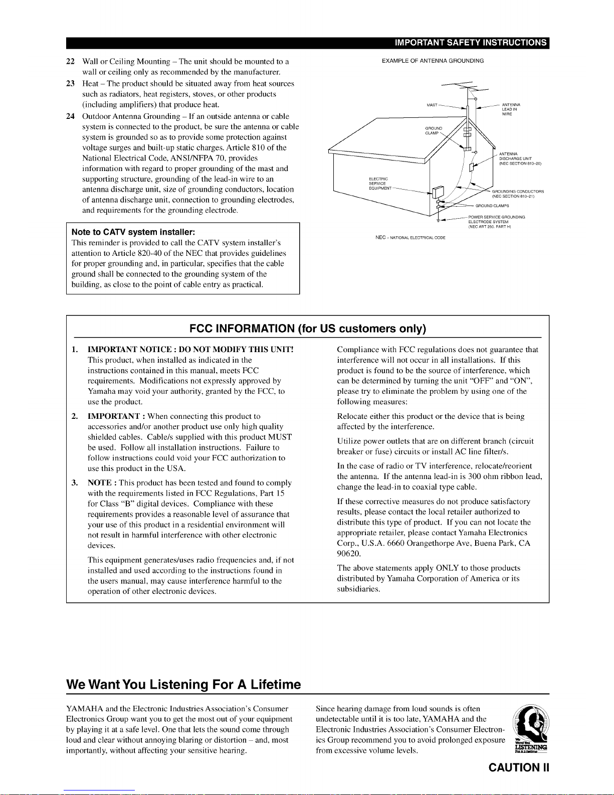
Outdoor Antenna Grounding - If an outside antenna or cable
system is connected to the product, be sure the antenna or cable
system is grounded so as to provide some protection against
voltage surges and built-up static charges. Article 810 of the
National Electrical Code, ANSI/NFPA 70, provides
information with regard to proper grounding of the mast and
supporting structure, grounding of the lead-in wire to an
antenna discharge unit, size of grounding conductors, location
of antenna discharge unit, connection to grounding electrodes,
and requirements for the grounding electrode.
Note to CATV system installer:
This reminder is provided to call the CATV system installer's
attention to Article 820-40 of the NEC that provides guidelines
for proper grounding and, in particular, specifies that the cable
ground shall be connected to the grounding system of the
building, as close to the point of cable entry as practical.
EXAMPLE OF ANTENNA GROUNDING
ANTENNA
LEADIN
WiRE
ELECTRIC
SERVICE
NEC - NATIONAL ELECTRICAL CODE
DISCHARGE UNIT
(NEC SECTION 81 _20)
(NEC SECTION 810 21)
ELECTRODE SYSTEM
(NEC ART 250 PART H)
FCC INFORMATION (for US customers only)
1. IMPORTANT NOTICE : DO NOT MODIFY THIS UNIT!
This product, when installed as indicated in the
instructions contained in this manual, meets FCC
requirements. Modifications not expressly approved by
Yamaha may void your authority, granted by the FCC, to
use the product.
IMPORTANT : When connecting this product to
accessories and/or another product use only high quality
shielded cables. Cable/s supplied with this product MUST
be used. Follow all installation instructions. Failure to
follow instructions could void your FCC authorization to
use this product in the USA.
NOTE : This product has been tested and found to comply
with the requirements listed in FCC Regulations, Part 15
for Class "B" digital devices. Compliance with these
requirements provides a reasonable level of assurance that
your use of this product in a residential environment will
not result in harmful interference with other electronic
devices.
2,
3,
This equipment generates/uses radio frequencies and, if not
installed and used according to the instructions found in
the users manual, may cause interference harmful to the
operation of other electronic devices.
Compliance with FCC regulations does not guarantee that
interference will not occur in all installations. If this
product is found to be the source of interference, which
can be determined by turning the unit "OFF" and "ON",
please try to eliminate the problem by using one of the
following measures:
Relocate either this product or the device that is being
affected by the interference.
Utilize power outlets that are on different branch (circuit
breaker or fuse) circuits or install AC line filter/s.
In the case of radio or TV interference, relocate/reorient
the antenna. If the antenna lead-in is 300 ohm ribbon lead,
change the lead-in to coaxial type cable.
If these corrective measures do not produce satisfactory
results, please contact the local retailer authorized to
distribute this type of product. If you can not locate the
appropriate retailer, please contact Yamaha Electronics
Corp., U.S.A. 6660 Orangethorpe Ave, Buena Park, CA
90620.
The above statements apply ONLY to those products
distributed by Yamaha Corporation of America or its
subsidiaries.
We Want You Listening For A Lifetime
YAMAHA and the Electronic Industries Association's Consumer
Electronics Group want you to get the most out of your equipment
by playing it at a safe level. One that lets the sound come through
loud and clear without annoying blaring or distortion - and, most
importantly, without affecting your sensitive hearing.
Since hearing damage from loud sounds is often
undetectable until it is too late, YAMAHA and the
Electronic Industries Association's Consumer Electron-
ics Group recommend you to avoid prolonged exposure
from excessive volume levels.
L[STENIN_
_AL_
CAUTION II
1 To assure the finest performance, please read this manual
carefully. Keep it in a safe place for future reference.
2 Install this unit in a well ventilated, cool, dry, clean place with at
least 30 cm on the top, 10 cm on the right and left, and 10 cm at
the back of this unit -- away from direct sunlight, heat sources,
vibration, dust, moisture, and/or cold.
3 Locate this unit away from other electrical appliances, motors,
or transformers to avoid humming sounds. To prevent fire or
electrical shock, do not place this unit where it may get exposed
to rain, water, and/or any type of liquid.
4 Do not expose this unit to sudden temperature changes from
cold to hot, and do not locate this unit in a environment with
high humidity (i.e. a room with a humidifier) to prevent
condensation inside this unit, which may cause an electrical
shock, fire, damage to this unit, and/or personal injury.
5 On the top of this unit, do not place:
-Other components, as they may cause damage and/or discolora-
tion on the surface of this unit.
-Burning objects (i.e. candles), as they may cause fire, damage
to this unit, and/or personal injury.
-Containers with liquid in them, as they may cause electrical
shock to the user and/or damage to this unit.
6 Do not cover this unit with a newspaper, tablecloth, curtain, etc.
in order not to obstruct heat radiation. If the temperature inside
this unit rises, it may cause fire, damage to this unit, and/or
personal injury.
7 Do not plug in this unit to a wall outlet until all connections are
complete.
8 Do not operate this unit upside-down. It may overheat, possibly
causing damage.
9 Do not use force on switches, knobs and/or cords.
10 When disconnecting the power cord from the wall outlet, grasp
the plug; do not pull the cord.
11 Do not clean this unit with chemical solvents; this might
damage the finish. Use a clean, dry cloth.
12 Only voltage specified on this unit must be used. Using this unit
with a higher voltage than specified is dangerous and may cause
fire, damage to this unit, and/or personal injury. YAMAHA will
not be held responsible for any damage resulting from use of
this unit with a voltage other than specified.
13 To prevent damage by lightning, disconnect the power cord
from the wall outlet during an electrical storm.
14 Take care of this unit so that no foreign objects and/or liquid
drops inside this unit.
15 Do not attempt to modify or fix this unit. Contact qualified
YAMAHA service personnel when any service is needed. The
cabinet should never be opened for any reasons.
16 When not planning to use this unit for long periods of time (i.e.
vacation), disconnect the AC power plug from the wall outlet.
17 Be sure to read the "TROUBLESHOOTING" section on
common operating errors before concluding that this unit is
faulty.
18 Before moving this unit, press STANDBY/ON to set this unit in
the standby mode, and disconnect the AC power plug from the
wall outlet.
This unit is not disconnected from the AC power source as long
as it is connected to the wall outlet, even if this unit itself is
turned off. This state is called the standby mode. In this state,
this unit is designed to consume a very small quantity of power.
FOR CANADIAN CUSTOMERS
To prevent electric shock, match wide blade of plug to wide slot
and fully insert.
This Class B digital apparatus complies with Canadian ICES-
003.
IMPORTANT
Please record the serial number of this unit in the space below.
Model:
Serial No.:
The serial number is located on the rear of the unit.
Retain this Owner's Manual in a safe place for future reference.
For RAV-2000Zl
1 To assure the finest performance, please read this manual
carefully. Keep it in a safe place for future reference.
2 To avoid failure, do not spill liquid on the remote control.
3 Be sure to read the "Troubleshooting" section on common
operating errors before concluding that the remote control is
faulty.
FOR CANADIAN CUSTOMERS
This Class B digital apparatus complies with Canadian ICES-
003.
IMPORTANT
Please record the serial number of this unit in the space below.
Model:
Serial No.:
The serial number is located inside the battery compartment.
Retain this Owner's Manual in a safe place for future reference.
CAUTION III
[_o]]
COMPLIANCE INFORMATION STATEMENT
(DECLARATION OF CONFORMITY PROCEDURE)
Responsible Party:
Address:
Telephone:
Type of Equipment:
Model Name:
Yamaha Electronics Corp.,
6660 Orangethorpe Ave.
Buena Park, CA90620
714-522-9105
Remote Control
RAV-2000Z1
This device complies with Part 15 of the FCC Rules.
Operation is subject to the following conditions:
1) this device may not cause harmful interference, and
2) this device must accept any interference received including interference that may cause undesired operation.
See the user manual instructions if interference to radio reception is suspected.
FCC INFORMATION (U.S.A)
1. IMPORTANT NOTICE: DO NOT MODIFY THIS UNIT!
This product, when installed as indicated in the
instructions contained in this manual, meets FCC
requirements. Modifications not expressly approved by
Yamaha may void your authority, granted by the FCC, to
use the product.
2. IMPORTANT: When connecting this product to
accessories and/or another product use only high quality
shielded cables. Cable/s supplied with this product MUST
be used. Follow all installation instructions. Failure to
follow instructions could void your FCC authorization to
use this product in the USA.
3. NOTE: This product has been tested and found to comply
with the requirements listed in FCC Regulations, Part 15
for Class "B" digital devices. Compliance with these
requirements provides a reasonable level of assurance that
your use of this product in a residential environment will
not result in harmful interference with other electronic
devices.
This equipment generates/uses radio frequencies and, if not
installed and used according to the instructions found in
the users manual, may cause interference harmful to the
operation of other electronic devices.
Compliance with FCC regulations does not guarantee that
interference will not occur in all installations. If this
product is found to be the source of interference, which
can be determined by turning the product "OFF" and
"ON", please try to eliminate the problem by using one of
the following measures:
Relocate either this product or the device that is being
affected by the interference.
Utilize power outlets that are on different branch (circuit
breaker or fuse) circuits or install AC line filter/s.
In the case of radio or TV interference, relocate/reorient
the antenna. If the antenna lead-in is 300 ohm ribbon lead,
change the lead-in to coaxial type cable.
If these corrective measures do not produce satisfactory
results, please contact the local retailer authorized to
distribute this type of product. If you can not locate the
appropriate retailer, please contact Yamaha Electronics
Corp., 6660 Orangethorpe Ave. Buena Park, CA90620.
The above statements apply ONLY to those products
distributed by Yamaha Corporation of America or its
subsidiaries.
CAUTION IV
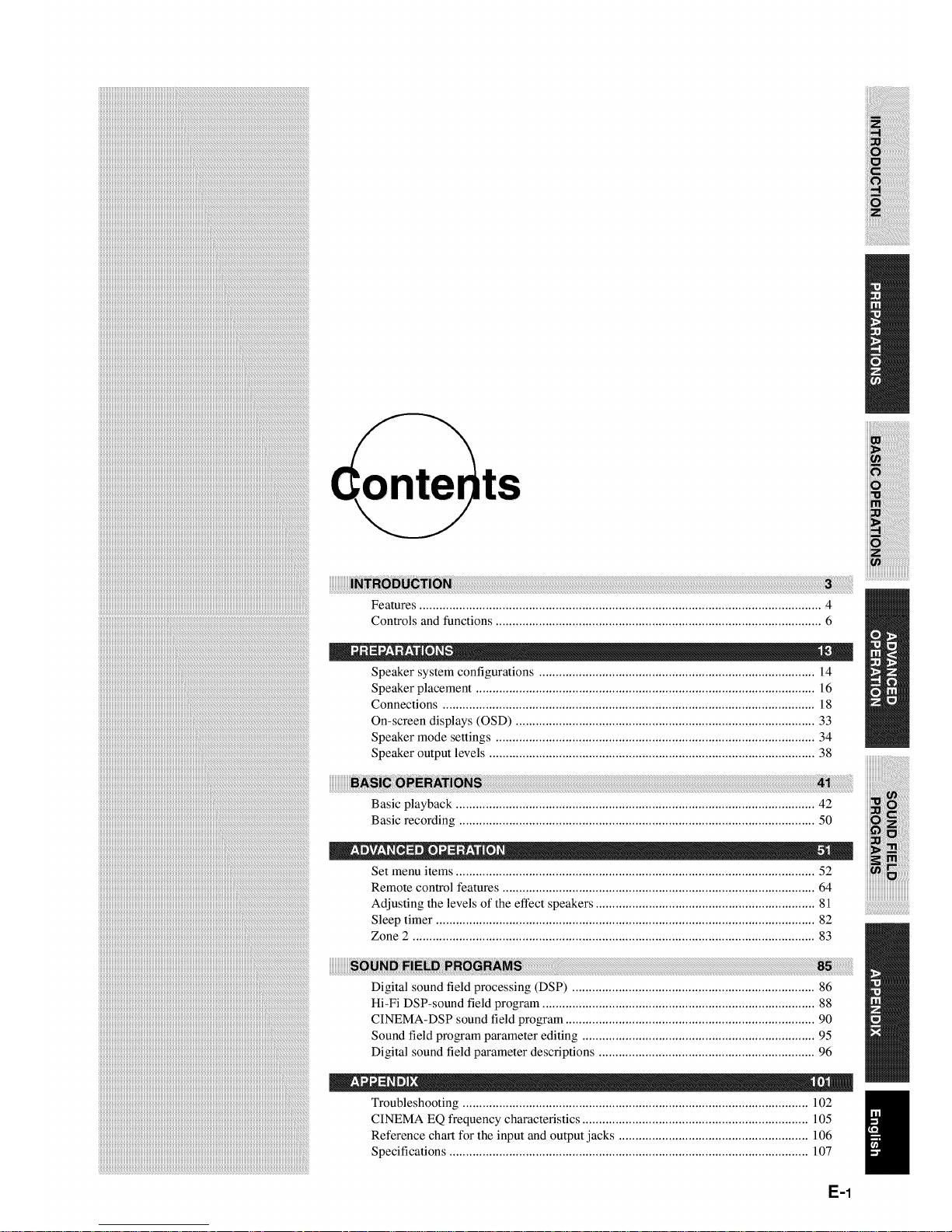
Features ......................................................................................................................... 4
Controls and functions .................................................................................................. 6
i
Speaker system configurations ................................................................................... 14
Speaker placement ...................................................................................................... 16
Connections ................................................................................................................ 18
On-screen displays (OSD) .......................................................................................... 33
Speaker mode settings ................................................................................................ 34
Speaker output levels .................................................................................................. 38
E-1
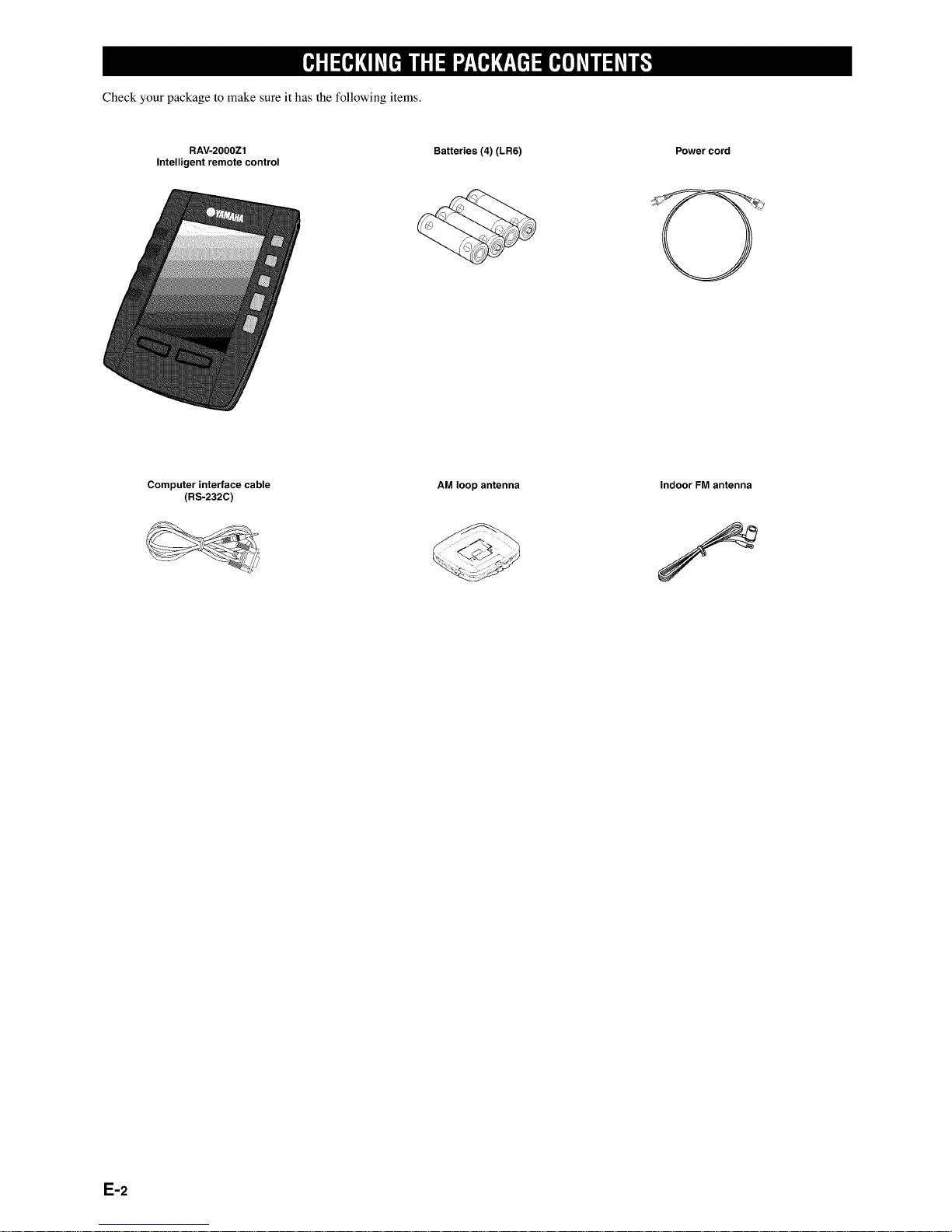
Check your package to make sure it has the following items.
RAV-20OOZ1
Intelligent remote control
Batteries (4) (LR6) Power cord
Computer interface cable
(RS-232C)
AM loop antenna
Indoor FM antenna
E-2

This section describes the features of the RX-Z1, and its controls and functions.
iiiiiiiiiiiiiiiiiiii i
Front panel .................................................................................................................... 6
Remote control .............................................................................................................. 8
Front panel display ...................................................................................................... 11
Rear panel ................................................................................................................... 12
F-3
• Built-in 8-channel power amplifier
• Main: 130 W + 130 W (8Q) RMS Output Power, 0.015% THD, 20 - 20,000 Hz
• Center: 130 W (SQ) RMS Output Power, 0.015% THD, 20 - 20,000 Hz
• Rear: 130 W + 130 W (8_2) RMS Output Power, 0.015% THD, 20 - 20,000 Hz
• Front: 45 W + 45 W (8_) RMS Output Power, 0.05% THD, 1 kHz
• Rear center: 130 W (8_2) RMS Output Power, 0.015% THD, 20 - 20,000 Hz
• Digital Sound Fields (DSP)
Technological advances in sound reproduction over the last 30 years have enhanced the listening experience with improved clarity, precision,
and power. However, something has been missing: the atmosphere and acoustic ambience of the public venue. Our Yamaha engineers have
extensively researched the nature of sound acoustics and the way sound reflects inside a room. We sent these engineers to famous theaters
and concert halls around the world to measure the acoustics of those venues with sophisticated microphones. The data they collected is used
to recreate these environments in digital sound fields. Some of these digital sound fields have been created using data measured at the
original venue; others have been created from combinations of data to form unique environments for specific purposes. Some have been
designed especially for music, and others especially for movies. Of course, this only solves half of the problem. Because these engineers have
no way of knowing the acoustics of your entertainment room, we have made it possible for you to adjust the various parameters of this data
to tailor each virtual venue to your taste. You can use these sound fields to enhance any source and in combination with any of the following
surround sound technologies.
• CINEMA-DSP: Dolby Digital + DSP and DTS + DSP
The Dolby Digital system and DTS system show their full capability in large movie theaters, because feature film soundtracks are designed
to be reproduced in such environments. It is difficult to recreate a sound environment similar to a movie theater in your entertainment room
because of the room size, wall materials, and the number of speakers in your entertainment system. Yamaha DSP technology makes it
possible for you to enjoy nearly the same sound experience as that of a large movie theater in your entertainment room by compensating for
lack of presence and dynamics in your entertainment room with Yamaha's original digital sound fields combined with Dolby Digital or DTS
soundtracks.H
• Virtual CINEMA DSP and SILENT CINEMA DSP
Yamaha developed the Virtual CINEMA DSP algorithm which allows you to experience the virtual sound fields without surround speakers.
This makes it possible for the RX-ZI to produce a full surround sound catering to the number of speakers you have. The RX-ZI also has a
SILENT CINEMA DSP algorithm which is achieved by the crosstalk processing applying the precise Head Related Transfer Function. You
can therefore enjoy listening to the CINEMA DSP soundfields on headphones.
• Various decoders to support the newest sound effect technology
This unit is equipped with the following signal format decoders.
rlrlFssCaCl
DIGITAL" EX
• Dolby Digital and Dolby Digital EX
The Matrix decoder enables 6.l-channel playback of"the 5. l-channel sources by extracting the rear center channel signals from the rear L/R
channel signals.
• DOLBY PRO LOGIC
• DOLBY PRO LOGIC ]I
DOLBY PRO LOGIC ]I is the improved technique to decode vast numbers of existing Dolby Surround programs. This new technology
enables a discrete 5-channel playback with two left and right main channels, a center channel, and two left and fight rear channels compared
with one limited rear channel for the conventional Pro Logic technology. Also the music mode is available for 2-channel sources in addition
to the movie mode.
EXTENDED
SURROUND
• DTS and DTS ES
The RX-ZI is also equipped with a DTS decoder, which uses a 5.l-channel system to create a full surround sound environment. It was
developed as a way to replace the analog soundtracks of movies with six channels of digital sound. In comparison with Dolby Digital, DTS
uses less compression to store the sound information. The newly presented DTS ES system reproduces digital sound similar to Dolby Digital
EX. The use of the rear center speaker along with the existing 5. l-channel speakers provides a fully immersive cinematic audio experience.
• DTS Neo: 6
Neo: 6 decodes the conventional 2-channel sources for 6-channel playback by the specific decoder. It enables playback with the full-range
channels with higher separation just like digital discrete signal playback. Two modes are available; "Music mode" for playing music sources
and "Cinema mode" for movies.
• DTS 96/24
DTS 96/24 achieves the high quality playback with all 5.1 channels at the sampling frequency 96 kHz/24 bit.
E-4
• Various input and output jacks
The RX-ZI has various output jacks tier audio and video signals as well as a digital recording output jack. Many input jacks are also available
for connection to multiple audio-video sources. All the video inputs and outputs have S-video jacks in addition to standard composite video
jacks tk_rimproved video picture quality. Component video input and output jacks are also available to deliver the excellent video signals
from DVD players and other high quality video sources. The coaxial and optical digital signal jacks (provided for direct transmission of
digital signals) automatically detect Dolby Digital, DTS, and PCM signals. A demodulator circuit is built into the Dolby Digital RF input so
you can connect it directly to the Dolby Digital RF signal output on your LD player. Additionally, there are six audio inputs tk_rdiscrete
multichannel reproduction from an external decoder.
The RX-Zl also comes with a monaural subwoofer jack and split subwoofer jacks which can reproduce delicate but powerful low frequency
effects.
• Intelligent remote control
The intelligent remote control can be used with most components that understand infrared (IR) remote control signals. Its easy-to-use touch
screen and its intuitive interface make it the perfect remote control tk_r every user.
The remote control (RC) is completely customizable. In the memory of the remote control, RC codes are stored to activate different brands of
all kinds of video and audio components. The remote control is set up by default to operate with YAMAHA components. If you have other
brands, you simply define the brands of your components when you use the remote control tk?r the first time.
The remote control can also learn RC codes from existing remote controls. It is designed to add components and functions, relabel buttons,
record macros and set timers. With the RAVedit software you create your own control panels and define your personal look.
rlrlr-Ssc_
DIGITALoEX
ID?l'RI1m,41"m_
Manufactured under license from Dolby Laboratories.
"Dolby", "Pro Logic", and the double-D symbol are trademarks of Dolby Laboratories.
ii iiiiiiiiiiiiiiiiiiiiiill
_!_!_i_!ilililililililililililililililililililililililil
i
iiiii i!i!i!i!i!i!i!i!i!i!i!i!i!i!i!i!i!i!i!i!!i!!ii!i
EXTENDED
k_ "DTS", "DTS-ES Extended Surround" and "Neo: 6" are trademarks of Digital Theater System, Inc.
SURROUND
E-5
I I
®
L I
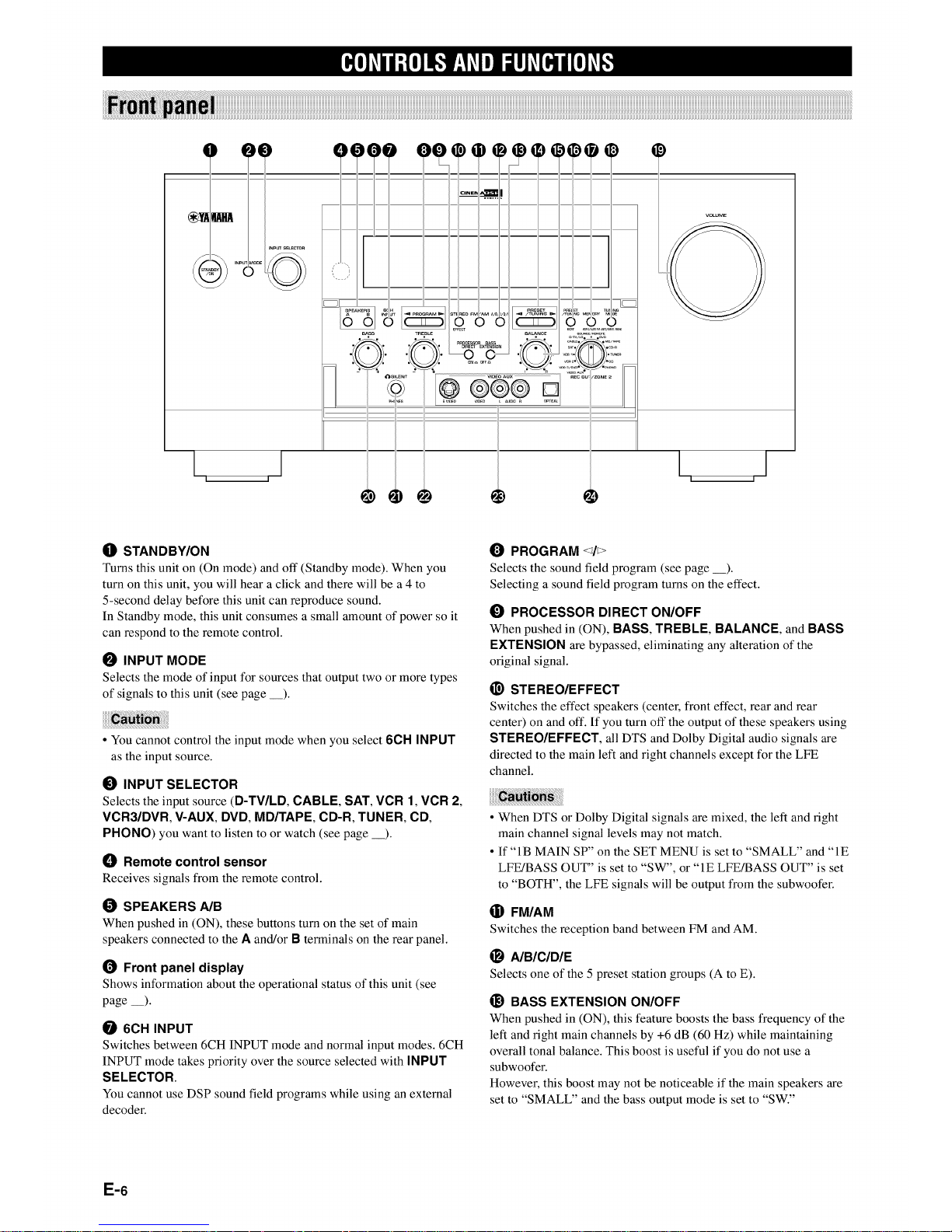
O STANDBY/ON
Turns this unit on (On mode) and off (Standby mode). When you
turn on this unit, you will hear a click and there will be a 4 to
5-second delay before this unit can reproduce sound.
In Standby mode, this unit consumes a small amount of power so it
can respond to the remote control.
I_ INPUT MODE
Selects the mode of input for sources that output two or more types
of signals to this unit (see page __).
• You cannot control the input mode when you select 6CH INPUT
as the input source.
I_) INPUT SELECTOR
Selects the input source (D-TV/LD, CABLE, SAT, VCR 1, VCR 2,
VCR3/DVR, V-AUX, DVD, MD/TAPE, CD-R, TUNER, CD,
PHONO) you want to listen to or watch (see page _).
O Remote control sensor
Receives signals from the remote control.
SPEAKERS A/B
When pushed in (ON), these buttons turn on the set of main
speakers connected to the A and/or B terminals on the rear panel.
1_ Front panel display
Shows information about the operational status of this unit (see
page __).
6CH INPUT
Switches between 6CH INPUT mode and normal input modes. 6CH
INPUT mode takes priority over the source selected with INPUT
SELECTOR.
You cannot use DSP sound field programs while using an external
decoder.
PROGRAM <_/_>
Selects the sound field program (see page __).
Selecting a sound field program turns on the effect.
_) PROCESSOR DIRECT ON/OFF
When pushed in (ON), BASS, TREBLE, BALANCE, and BASS
EXTENSION are bypassed, eliminating any alteration of the
original signal.
_) STEREO/EFFECT
Switches the effect speakers (center, front effect, rear and rear
center) on and off. If you turn off the output of these speakers using
STEREO/EFFECT, all DTS and Dolby Digital audio signals are
directed to the main left and right channels except for the LFE
channel.
• When DTS or Dolby Digital signals are mixed, the left and right
main channel signal levels may not match.
• If "IB MAIN SP" on the SET MENU is set to "SMALL" and "IE
LFE!BASS OUT" is set to "SW", or "IE LFE/BASS OUT" is set
to "BOTH", the LFE signals will be output from the subwoofer.
® FM/AM
Switches the reception band between FM and AM.
_) AIBICIDIE
Selects one of the 5 preset station groups (A to E).
_) BASS EXTENSION ON/OFF
When pushed in (ON), this feature boosts the bass frequency of the
left and right main channels by +6 dB (60 Hz) while maintaining
overall tonal balance. This boost is useful if you do not use a
subwoofer.
However, this boost may not be noticeable if the main speakers are
set to "SMALL" and the bass output mode is set to "SW."
E-6
PRESET/TUNING El>
Selects preset station number 1 to 8 when the colon (:) appears on
the left of the band indication ("FM" or "AM") on the front panel
display, and selects the tuning frequency when the colon (:) does not
appear.
_) BALANCE
Controls the balance of the sound levels coming from the left and
right main speaker(s). Setting this control to the center position is
appropriate for most situations.
_} PRESET/TUNING EDIT
Switches the function of PRESET/TUNING <_/> (the colon (:)
turns on or off) between selecting a preset station number and
tuning.
This button is also used to exchange the assignment of two preset
stations with each other.
MEMORY (MAN'L/AUTO FM)
Stores a station in the memory. Hold down this button for more than
3 seconds to start automatic presetting stations.
_) TUNING MODE (AUTO/MAN'L MONO)
Switches the tuning mode between automatic and manual. To select
the automatic tuning mode, press this button so that the "AUTO"
indicator lights up on the front panel display. To select the manual
tuning mode, press this button so that the "AUTO" indicator does
not light up.
_) VOLUME
Controls the output level of all audio channels.
This does not affect the REC OUT level.
I_) BASS
Adjusts the low frequency response for the left and right main
speaker channels.
Turn the control to the right to increase the low frequency response
and turn the control to the left to decrease the low frequency
response.
VIDEO AUX
Inputs audio and video signals from a portable external source such
as a video camera.
_) REC OUT/ZONE 2
Selects the source you want to direct to the audio/video recorder and
ZONE 2 outputs independent of the source you are listening to in
the main room. When set to the SOURCE/REMOTE position, the
input source is directed to all outputs.
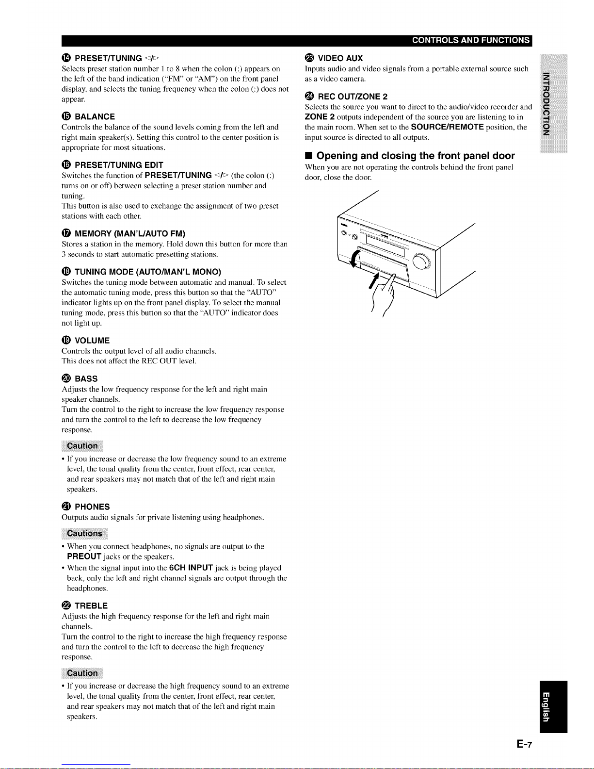
• Opening and closing the front panel door
When you are not operating the controls behind the front panel
door, close the door.
• If you increase or decrease the low frequency sound to an extreme
level, the tonal quality from the center, front effect, rear center,
and rear speakers may not match that of the left and right main
speakers.
PHONES
Outputs audio signals for private listening using headphones.
• When you connect headphones, no signals are output to the
PREOUT jacks or the speakers.
• When the signal input into the 6CH INPUT jack is being played
back, only the left and right channel signals are output through the
headphones.
TREBLE
Adjusts the high frequency response for the left and right main
channels.
Turn the control to the right to increase the high frequency response
and turn the control to the left to decrease the high frequency
response.
• If you increase or decrease the high frequency sound to an extreme
level, the tonal quality from the center, front effect, rear center,
and rear speakers may not match that of the left and right main
speakers.
E-7
O
O
0
0
@
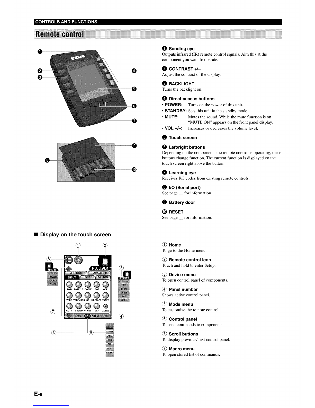
O Sending eye
Outputs infrared (IR) remote control signals. Aim this at the
component you want to operate.
0 CONTRAST +/-
Adjust the contrast of the display.
0 BACKLIGHT
Turns the backlight on.
() Direct-access buttons
• POWER: Turns on the power of this unit.
• STANDBY: Sets this unit in the standby mode.
• MUTE: Mutes the sound. While the mute function is on,
"MUTE ON" appears on the front panel display.
• VOL +1-: Increases or decreases the volume level.
O Touch screen
1_ Left/right buttons
Depending on the components the remote control is operating, these
buttons change function. The current function is displayed on the
touch screen right above the button.
Learning eye
Receives RC codes from existing remote controls.
I/0 (Serial port)
See page __ for information.
0 Battery door
_) RESET
See page __ for intk_rmation.
• Display on the touch screen
@@@@@
D?D D-TWLD CABLE SAT VCR1
@@®@@
VCR2 VCR31DVR CD MD/TAPE TUNER
@®@®
iPHONO ¥-AUX 6CH ZONE2
@ Home
To go to the Home menu.
@ Remote control icon
Touch and hold to enter Setup.
@ Device menu
To open control panel of components.
@ Panel number
Shows active control panel.
@ Mode menu
To customize the remote control.
@ Control panel
To send commands to components.
@ Scroll buttons
To display previous/next control panel.
@ Macro menu
To open stored list of commands.
E-8
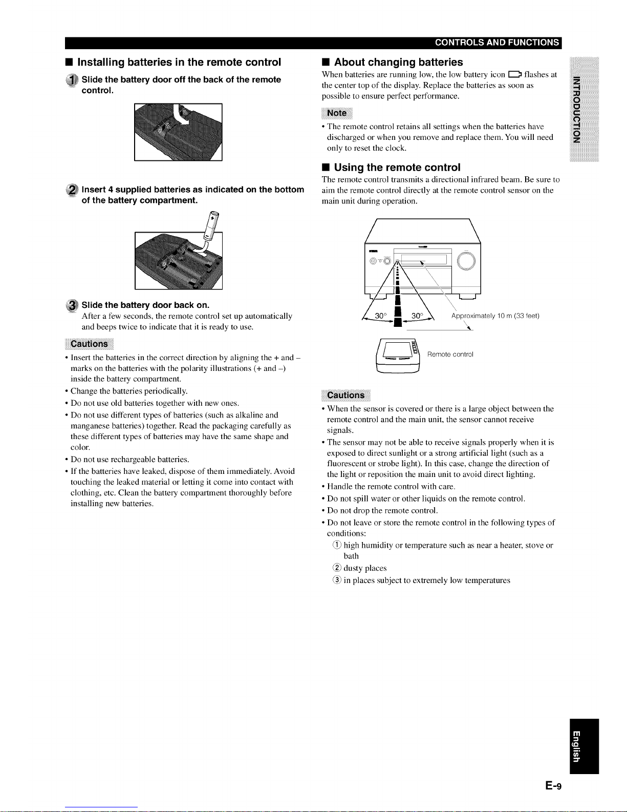
• Installing batteries in the remote control
_ lide the battery door off the back of the remote
control.
• About changing batteries
When batteries are running low, the low battery icon _ flashes at
the center top of the display. Replace the batteries as soon as
possible to ensure perfect performance.
_ nsert 4 supplied batteries as indicated on the bottom
of the battery compartment.
• The remote control retains all settings when the batteries have
discharged or when you remove and replace them. You will need
only to reset the clock.
• Using the remote control
The remote control transmits a directional infrared beam. Be sure to
aim the remote control directly at the remote control sensor on the
main unit during operation.
_ lide the battery door back on.
After a few seconds, the remote control set up automatically
and beeps twice to indicate that it is ready to use.
• Insert the batteries in the correct direction by aligning the + and -
marks on the batteries with the polarity illustrations (+ and -)
inside the battery compartment.
• Change the batteries periodically.
• Do not use old batteries together with new ones.
• Do not use different types of batteries (such as alkaline and
manganese batteries) together. Read the packaging carefully as
these different types of batteries may have the same shape and
color.
° Do not use rechargeable batteries.
• If the batteries have leaked, dispose of them immediately. Avoid
touching the leaked material or letting it come into contact with
clothing, etc. Clean the battery compartment thoroughly before
installing new batteries.
Approximately 10 m (33 feet)
Remote control
• When the sensor is covered or there is a large object between the
remote control and the main unit, the sensor cannot receive
signals.
• The sensor may not be able to receive signals properly when it is
exposed to direct sunlight or a strong artificial light (such as a
fluorescent or strobe light). In this case, change the direction of
the light or reposition the main unit to avoid direct lighting.
• Handle the remote control with care.
• Do not spill water or other liquids on the remote control.
° Do not drop the remote control.
• Do not leave or store the remote control in the tbllowing types of
conditions:
_) high humidity or temperature such as near a heater, stove or
bath
_2) dusty places
2) in places subject to extremely low temperatures
E-9
[_o_ij;Io_l_.,_ V'-I_.Im]_o,._ilI[O_.,._
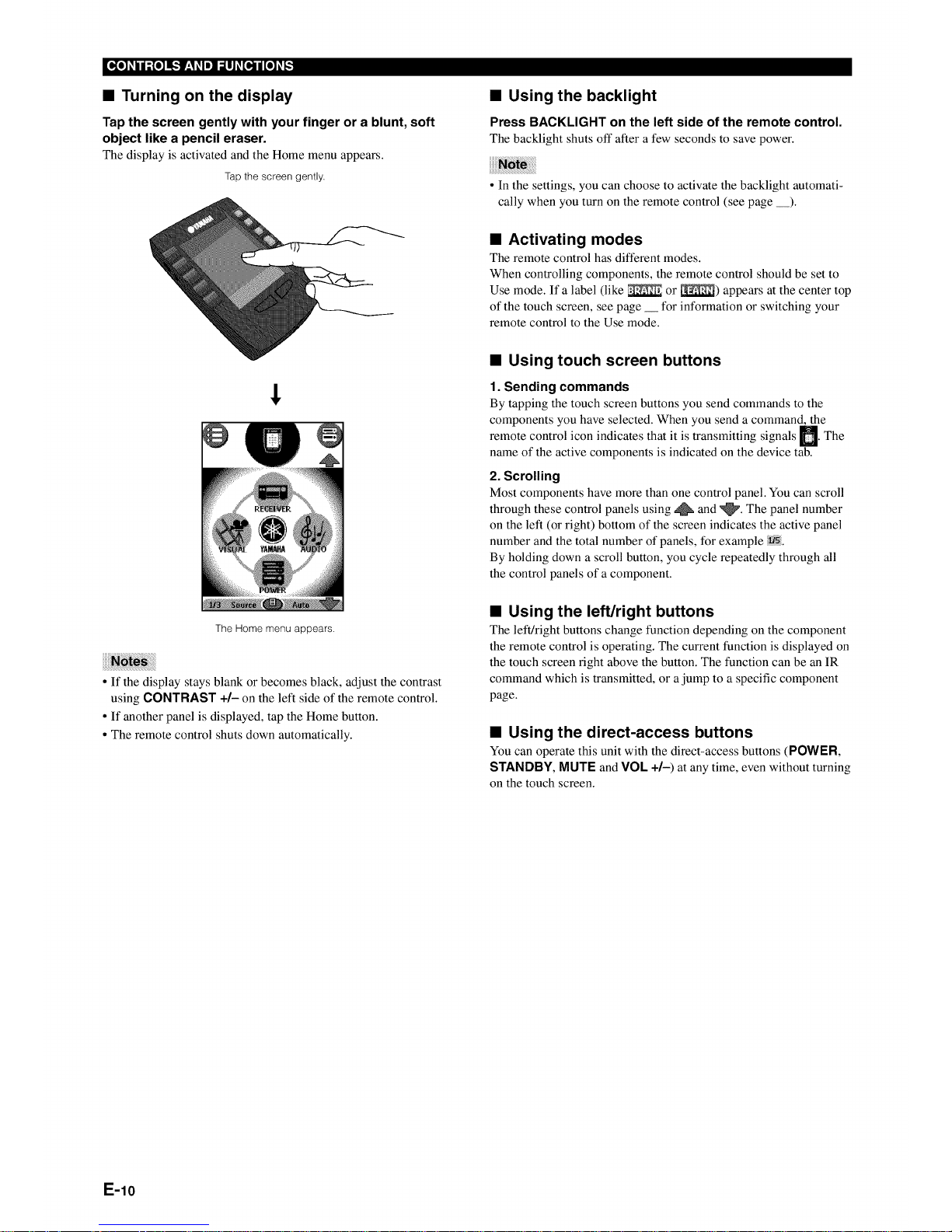
• Turning on the display
Tap the screen gently with your finger or a blunt, soft
object like a pencil eraser.
The display is activated and the Home menu appears.
Tap the screen gently.
The Home menu appears.
• If the display stays blank or becomes black, adjust the contrast
using CONTRAST +/- on the left side of the remote control.
• If another panel is displayed, tap the Home button.
• The remote control shuts down automatically.
• Using the backlight
Press BACKLIGHT on the left side of the remote control.
The backlight shuts oil"after a few seconds to save power.
• In the settings, you can choose to activate the backlight automati-
cally when you turn on the remote control (see page __).
• Activating modes
The remote control has different modes.
When controlling components, the remote control should be set to
Use mode. If a label (like _ or _) appears at the center top
of the touch screen, see page __ for information or switching your
remote control to the Use mode.
• Using touch screen buttons
1. Sending commands
By tapping the touch screen buttons you send commands to the
components you have selected. When you send a command, the
control icon indicates that it is transmitting signals M. The
remote
name of the active components is indicated on the device tab.
2. Scrolling
Most components have more than one control panel. You can scroll
through these control panels using _ and _. The panel number
on the left (or right) bottom of the screen indicates the active panel
number and the total number of panels, for example _.
By holding down a scroll button, you cycle repeatedly through all
the control panels of a component.
• Using the left/right buttons
The left/right buttons change function depending on the component
the remote control is operating. The current tunction is displayed on
the touch screen right above the button. The tunction can be an IR
command which is transmitted, or a jump to a specific component
page.
• Using the direct-access buttons
You can operate this unit with the direct-access buttons (POWER,
STANDBY, MUTE and VOL +/-) at any time, even without turning
on the touch screen.
E-10
[_o_hj;Io_n_,._ I_'ll]_o,,_ijI_o_._
e
mlllllllllllm
lllllllllllllll
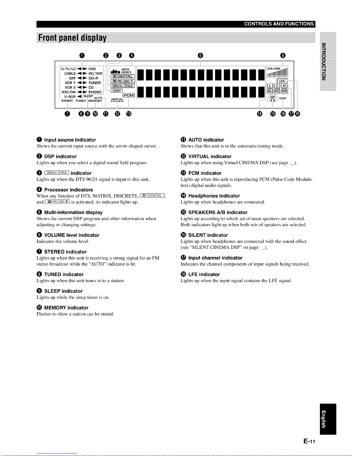
O Input source indicator
Shows the current input source with the arrow-shaped cursor.
O DSP indicator
Lights up when you select a digital sound field program.
[ 96kHz/24bit ) indicator
Lights up when the DTS 96/24 signal is input to this unit.
() Processor indicators
When any function of DTS, MATRIX, DISCRETE, ( no DJGJTAt_1,
and ( DDPROLOGIC/X) is activated, its indicator lights up.
Multi-information display
Shows the current DSP program and other information when
adjusting or changing settings.
(_ VOLUME level indicator
Indicates the volume level.
STEREO indicator
Lights up when this unit is receiving a strong signal for an FM
stereo broadcast while the "AUTO" indicator is lit.
TUNED indicator
Lights up when this unit tunes in to a station.
O SLEEP indicator
Lights up while the sleep timer is on.
_) MEMORY indicator
Flashes to show a station can be stored.
(i) AUTO indicator
Shows that this unit is in the automatic tuning mode.
_) VIRTUAL indicator
Lights up when using Virtual CINEMA DSP (see page _).
_) PCM indicator
Lights up when this unit is reproducing PCM (Pulse Code Modula-
tion) digital audio signals.
(_ Headphones indicator
Lights up when headphones are connected.
_) SPEAKERS A/B indicator
Lights up according to which set of main speakers are selected.
Both indicators light up when both sets of speakers are selected.
_) SILENT indicator
Lights up when headphones are connected with the sound effect
(see "SILENT CINEMA DSP" on page __).
(_ Input channel indicator
Indicates the channel components of input signals being received.
_) LFE indicator
Lights up when the input signal contains the LFE signal.
E-11
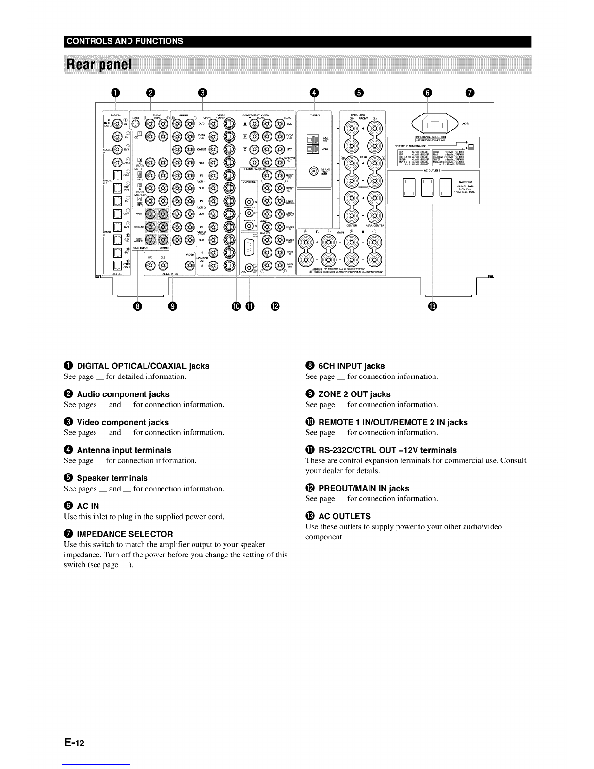
O DIGITAL OPTICAUCOAXIAL jacks
See page __ for detailed information.
O Audio component jacks
See pages __ and __ for connection information.
O Video component jacks
See pages __ and __ for connection information.
!_ Antenna input terminals
See page __ for connection information.
Speaker terminals
See pages __ and __ for connection information.
(_ AC IN
Use this inlet to plug in the supplied power cord.
IMPEDANCE SELECTOR
Use this switch to match the amplifier output to your speaker
impedance. Turn off the power before you change the setting of this
switch (see page __).
6CH INPUT jacks
See page __ for connection information.
_) ZONE 2 OUT jacks
See page __ for connection information.
_) REMOTE 1 IN/OUT/REMOTE 2 IN jacks
See page __ for connection information.
(]i) RS-232C/CTRL OUT +12V terminals
These are control expansion terminals for commercial use. Consult
your dealer for details.
_1 PREOUT/MAIN IN jacks
See page __ for connection information.
_) AC OUTLETS
Use these outlets to supply power to your other audio/video
component.
E-12
iiiiiiiiiiiiiiiiiiiiiiiiiiiiiiiiiiiiiiiiiiiiiiiiiiiiiiiiiiiiiiiiiiiiiiiiiii_!i_iiiiiiiiiiiiiiiiiiiiiiiiiiiiiiiiiiiiiiiiiiiiiiiiiiiiiiiiiiiiiiiiiiiiiiiiiiiiiiiiiiiiiiiiiiiiiiiiiiiiiiiiiiiiiiiiiiiiiiiiiiiiiiiiiiiiiiiiiiiiiiiiiiiiiiiiiiiiiiiiiiiiiiiiiiiiiiiiiiiiiiiiiiiiiiiiiiiiiiiiiiiiiiiiiiiiiiiiiiiiiiiiiiiiiiiiii_ii_ oo_o_o_ _ o_ oo_o_ _ _o_ _ _ _ _ _,_ _o
iiiiiiiiiiiiiiiiiiiiiiiiiiiiiiiiiiiiiiiiiiiiiiiiiiiiiiiiiiiiiiiiiiiiiiiiiiiiiiiiiiiiiiiiiiiiiiiiiiiiiiiiiiiiiiiiiiiiiiiiiiiiiiiiiiiiiiiiii_i__!i!iiiiiiiiiiiiiiiiiiiiiiiiiiiiiiiiiiiiiiiiiiiiiiiiiiiiiiiiiiiiiiiiiiiiiiiiiiiiiiiiiiiiiiiiiiiiiiiiiiiiiiiiiiiiiiiiiiiiiiiiiiiiiiiiiiiii_i_ii_!_!_!_i_i_i_i_!_i_i_i_!_!_!_)_!_!_!_i_i_i_i_i_i_i_i!_ii_i!i_!i_iii!i_!i!_ii_i!_i!i!_!i!_i!i!_!i_i!i_i!_i_i_i_i_i_i_i!_ii_i!i_!i_iii!_!i_ii!_!i_;_!i!_!i_i_i!_!i!_i!i!_!i_i!i_i!_i_i_i_i_i_i_i!_ii_i!i_!i_iii!i_!i!_ii_i!_i!i!_!i!_i!i!_!i_i!i_i!_i_i_i_i_i_i_i!_ii_i!i_!i_iii!_!i_ii!_!_!i_i_i!_!!_i!_i!_i!_i!_i!_i!_i!_i!_i!_i!_i!_i!_ii_i!_!i_ii_i!
iiiiiiiiiiiiiiiiiiiiiiiiiiiiiiiiiiiiiiiiiiiiiiiiiiiiiiiiiiiiiiiiiiiiiiiiiiiiiiiiiiiiiiiiiiiiiiiiiiiiiiiiiiiiiiiiiiiiiiiiiiiiiiiiiiiiiiiiiiiiiiiiiiiiiiiiiiiiiiiiiiiiiiiiiiiiiiiiiiiiiiiii_i_iiii!i!iiiiiiiii
i' i_
E-13
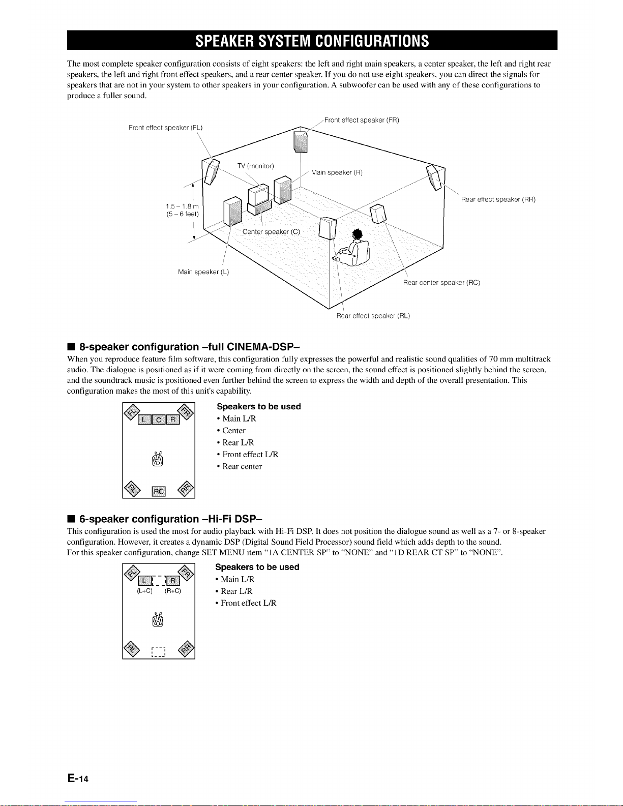
The most complete speaker configuration consists of eight speakers: the left and right main speakers, a center speaker, the left and right rear
speakers, the left and fight front effect speakers, and a rear center speaker. If you do not use eight speakers, you can direct the signals tbr
speakers that are not in your system to other speakers in your configuration. A subwoofer can be used with any of these configurations to
produce a fuller sound.
Front effect speaker (FL)
/Front effect speaker (FR)
1.5 1.8m
(5 - 6feet)
/
Main speaker (L)
TV (monitor)
Center speaker (_
/ Main speaker (R)
Rear effect speaker (RR)
_ear cen_er speaker (RC)
Rear effect speaker (RL)
• 8-speaker configuration -full CINEMA-DSP-
When you reproduce feature film software, this configuration fully expresses the powerful and realistic sound qualities of 70 mm multitrack
audio. The dialogue is positioned as if it were coming from directly on the screen, the sound effect is positioned slightly behind the screen,
and the soundtrack music is positioned even further behind the screen to express the width and depth of the overall presentation. This
configuration makes the most of this unit's capability.
Speakers to be used
• Main L/R
• Center
• Rear L/R
° Front effect L/R
• Rear center
• 6-speaker configuration -Hi-Fi DSP-
This configuration is used the most for audio playback with Hi-Fi DSP. It does not position the dialogue sound as well as a 7- or 8-speaker
configuration. However, it creates a dynamic DSP (Digital Sound Field Processor) sound field which adds depth to the sound.
For this speaker configuration, change SET MENU item "1A CENTER SP" to "NONE" and "1D REAR CT SP" to "NONE".
(L+C) (R+C)
[22"
Speakers to be used
• Main L/R
• Rear L_
• Front effect L/R
E-14
g"]",,J:!',3N:1-'[,."]_,.')iJ_ [_o]II_I_o]_:
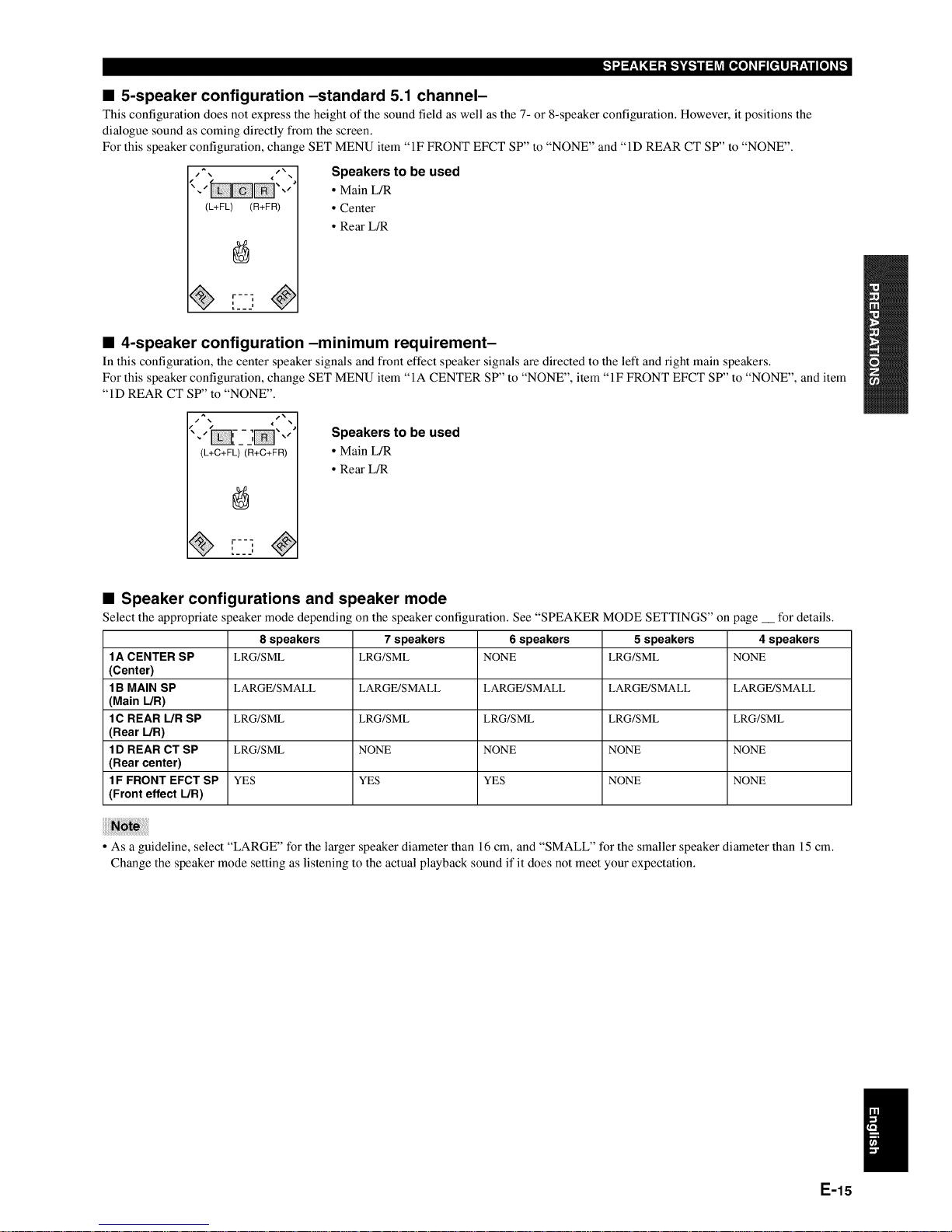
• 5-speaker configuration-standard 5.1 channel-
This configuration does not express the height of the sound field as well as the 7- or 8-speaker configuration. However, it positions the
dialogue sound as coming directly from the screen.
For this speaker configuration, change SET MENU item "IF FRONT EFCT SP" to "NONE" and "ID REAR CT SP" to "NONE".
(L+FL) (R+FR)
[2J
Speakers to be used
• Main L/R
• Center
• Rear L/R
• 4-speaker configuration-minimum requirement-
In this configuration, the center speaker signals and front effect speaker signals are directed to the left and right main speakers.
For this speaker configuration, change SET MENU item "IA CENTER SP" to "NONE", item "IF FRONT EFCT SP" to "NONE", and item
"ID REAR CT SP" to "NONE".
j_
(L+C+FL) (R+C+FR)
r--]
Speakers to be used
• Main L/R
• Rear L_
• Speaker configurations and speaker mode
Select the appropriate speaker mode depending on the speaker configuration. See "SPEAKER MODE SETTINGS" on page __ for details.
8 speakers 7 speakers 6 speakers 5 speakers 4 speakers
1A CENTER SP LRG/SML LRG/SML NONE LRG/SML NONE
(Center)
1B MAIN SP LARGE/SMALL LARGE/SMALL LARGE/SMALL LARGE/SMALL LARGE/SMALL
(Main L/R)
1C REAR L/R SP LRG/SML LRG/SML LRG/SML LRG/SML LRG/SML
(Rear L/R)
1D REAR CT SP LRG/SML NONE NONE NONE NONE
(Rear center)
1F FRONT EFCT SP YES YES YES NONE NONE
(Front effect L/R)
• As a guideline, select "LARGE" for the larger speaker diameter than 16 cm, and "SMALL" for the smaller speaker diameter than 15 cm.
Change the speaker mode setting as listening to the actual playback sound if it does not meet your expectation.
E-15
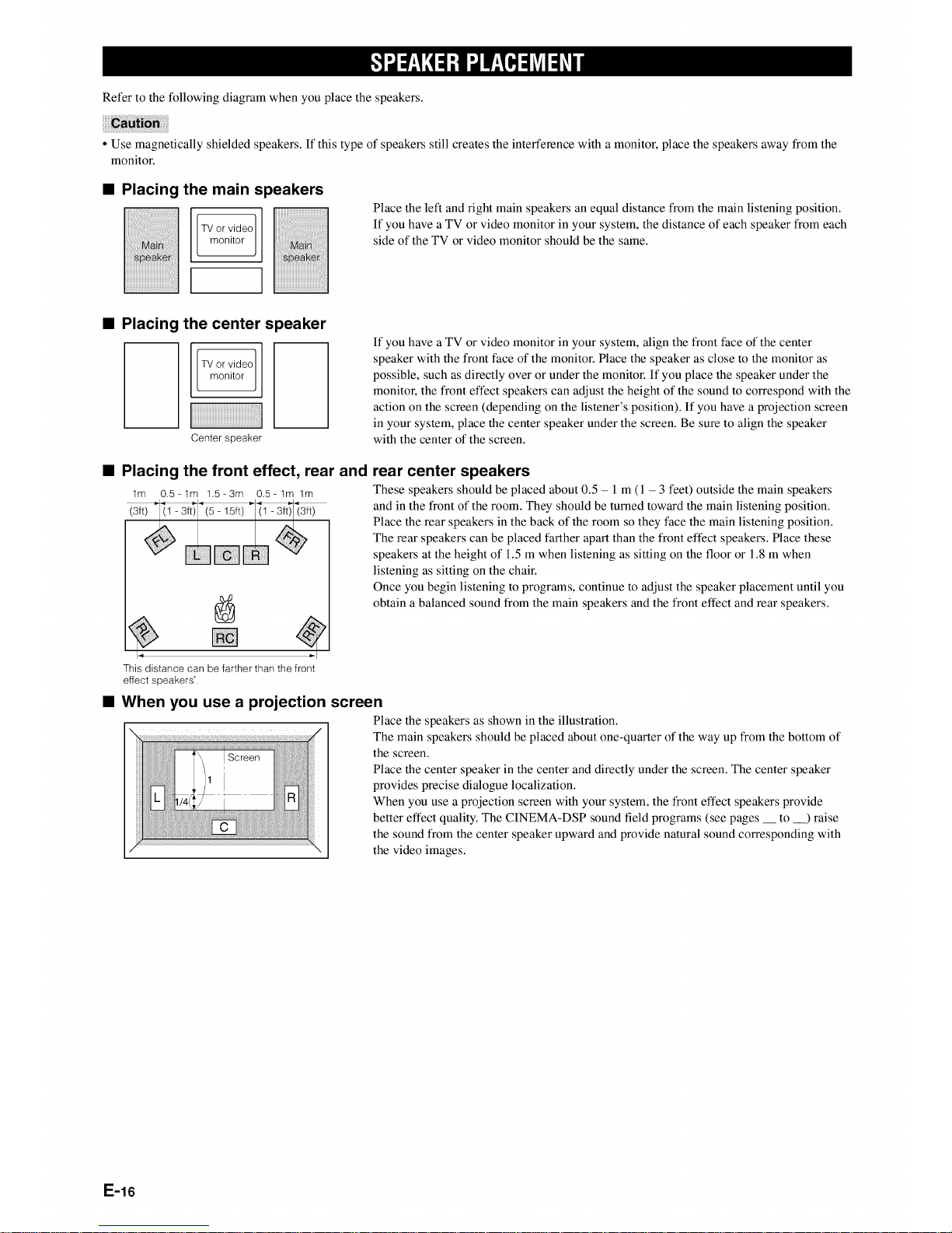
Refer to the following diagram when you place the speakers.
• Use magnetically shielded speakers. If this type of speakers still creates the interference with a monitor, place the speakers away from the
monitor.
• Placing the main s
TV or video
monitor
)eakers
Place the left and right main speakers an equal distance from the main listening position.
If you have a TV or video monitor in your system, the distance of each speaker from each
side of the TV or video monitor should be the same.
• Placing the center speaker
Center speaker
F
• Placing the front effect, rear and
lm 0.5-1m 1.5=3m 0.5-1m lm
If you have a TV or video monitor in your system, align the front face of the center
speaker with the front face of the monitor. Place the speaker as close to the monitor as
possible, such as directly over or under the monitor. If you place the speaker under the
monitor, the front effect speakers can adjust the height of the sound to correspond with the
action on the screen (depending on the listener's position). If you have a projection screen
in your system, place the center speaker under the screen. Be sure to align the speaker
with the center of the screen.
rear center speakers
These speakers should be placed about 0.5 - l m (1 - 3 feet) outside the main speakers
and in the front of the room. They should be turned toward the main listening position.
Place the rear speakers in the back of the room so they face the main listening position.
The rear speakers can be placed farther apart than the front effect speakers. Place these
speakers at the height of 1.5 m when listening as sitting on the floor or 1.8 m when
listening as sitting on the chair.
Once you begin listening to programs, continue to adjust the speaker placement until you
obtain a balanced sound from the main speakers and the front effect and rear speakers.
This distance can be farther than thefront
effect speakers'.
• When you use a projection screen
Place the speakers as shown in the illustration.
The main speakers should be placed about one-quarter of the way up from the bottom of
the screen.
Place the center speaker in the center and directly under the screen. The center speaker
provides precise dialogue localization.
When you use a projection screen with your system, the front effect speakers provide
better effect quality. The CINEMA-DSP sound t]eld programs (see pages to ) raise
the sound from the center speaker upward and provide natural sound corresponding with
the video images.
E-16
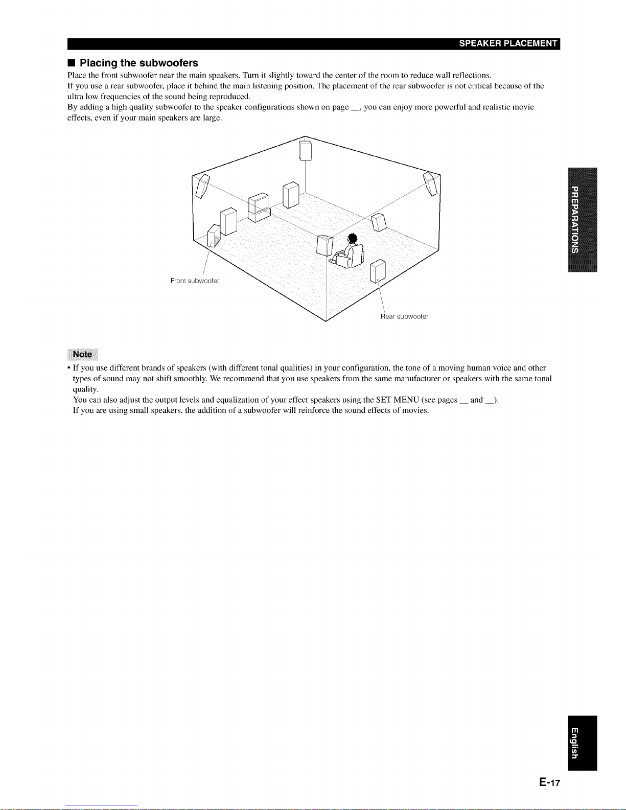
• Placing the subwoofers
Place the front subwoofer near the main speakers. Turn it slightly toward the center of the room to reduce wall reflections.
If you use a rear subwoofer, place it behind the main listening position. The placement of the rear subwoofer is not critical because of the
ultra low frequencies of the sound being reproduced.
By adding a high quality subwoofer to the speaker configurations shown on page __, you can enjoy more powerful and realistic movie
effects, even if your main speakers are large.
/
Frontsubwoofer
/
Rear subwoofer
• If you use different brands of speakers (with different tonal qualities) in your configuration, the tone of a moving human voice and other
types of sound may not shift smoothly. We recommend that you use speakers from the same manufacturer or speakers with the same tonal
quality.
You can also adjust the output levels and equalization of your effect speakers using the SET MENU (see pages __ and __).
If you are using small speakers, the addition of a subwoofer will reinforce the sound effects of movies.
E-17
I[,,_,_o_
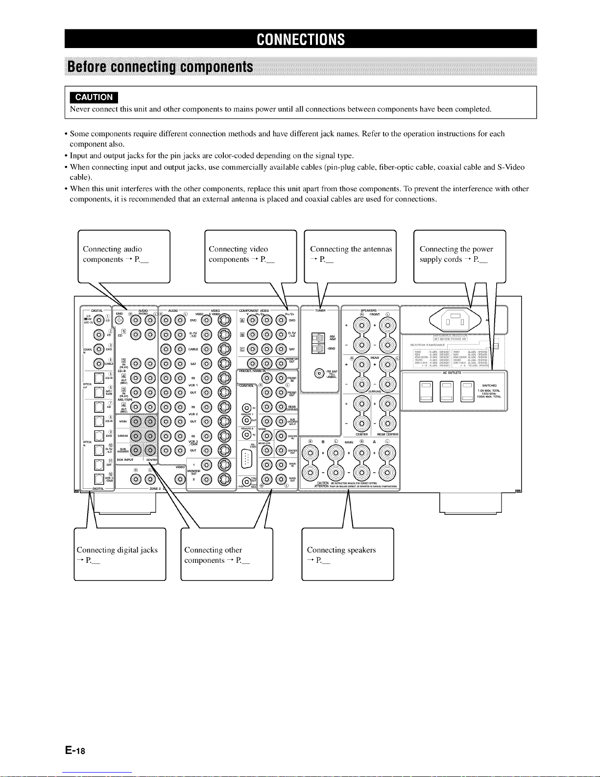
Never connect this unit and other components to mains power until all connections between components have been completed.
• Some components require different connection methods and have different jack names. Refer to the operation instructions for each
component also.
• Input and output jacks for the pin jacks are color-coded depending on the signal type.
• When connecting input and output jacks, use commercially available cables (pin-plug cable, fiber-optic cable, coaxial cable and S-Video
cable).
• When this unit interferes with the other components, replace this unit apart from those components. To prevent the interference with other
components, it is recommended that an external antenna is placed and coaxial cables are used for connections.
Connecting audio
onents _ P.
Connecting video
components _ P.
\
Connecting the antennas Connecting the power
supply cords _ R
II I1_1
os@@
£@ @
cu-R
£@@
£@ @
£@
@
@o@
Connecting digital jacks Connecting other
components _ P.
Connecting speakers
E-18
This unit has digital jacks for direct transmission of digital signals through either coaxial or fiber optic cables.
• DIGITAL OUTPUT jacks and analog OUT (REC) jacks are independent. Only digital signals are output from DIGITAL OUTPUT jacks
and analog signals from OUT (REC)jacks.
• You can use the digital jacks to input PCM, Dolby Digital and DTS bitstreams.
• When you connect components to both the COAXIAL and OPTICAL jacks, priority is given to the input signals from the COAXIAL jack.
• The OPTICAL jacks on this unit conform to the EIA standard. If you use a fiber optic cable that does not conform to this standard, this unit
may not function properly.
• You can designate the input for each digital jacks according to your component by using "8 I/O ASSIGNMENT" on the SET MENU (see
page __ for details).
Digital input jacks of this unit support the following sampling frequency.
• 32 kHz
• 44.1 kHz: CD, CD-R and MD
• 48 kHz: DVD (48 kHz mode)
° 96 kHz: DVD (96 kHz mode)
• 192 kHz (coaxial input only): DVD audio (2-channel)
Before you connect any components, disconnect the power supply to all the components you plan to connect including this unit and deter-
mine which jacks are for the left and fight channels and for input and output.
When you connect other YAMAHA audio component (such as a CD player or changer, MD deck, or tape deck), connect to terminals with the
same number labels. Yamaha applies this labelling system to all its products.
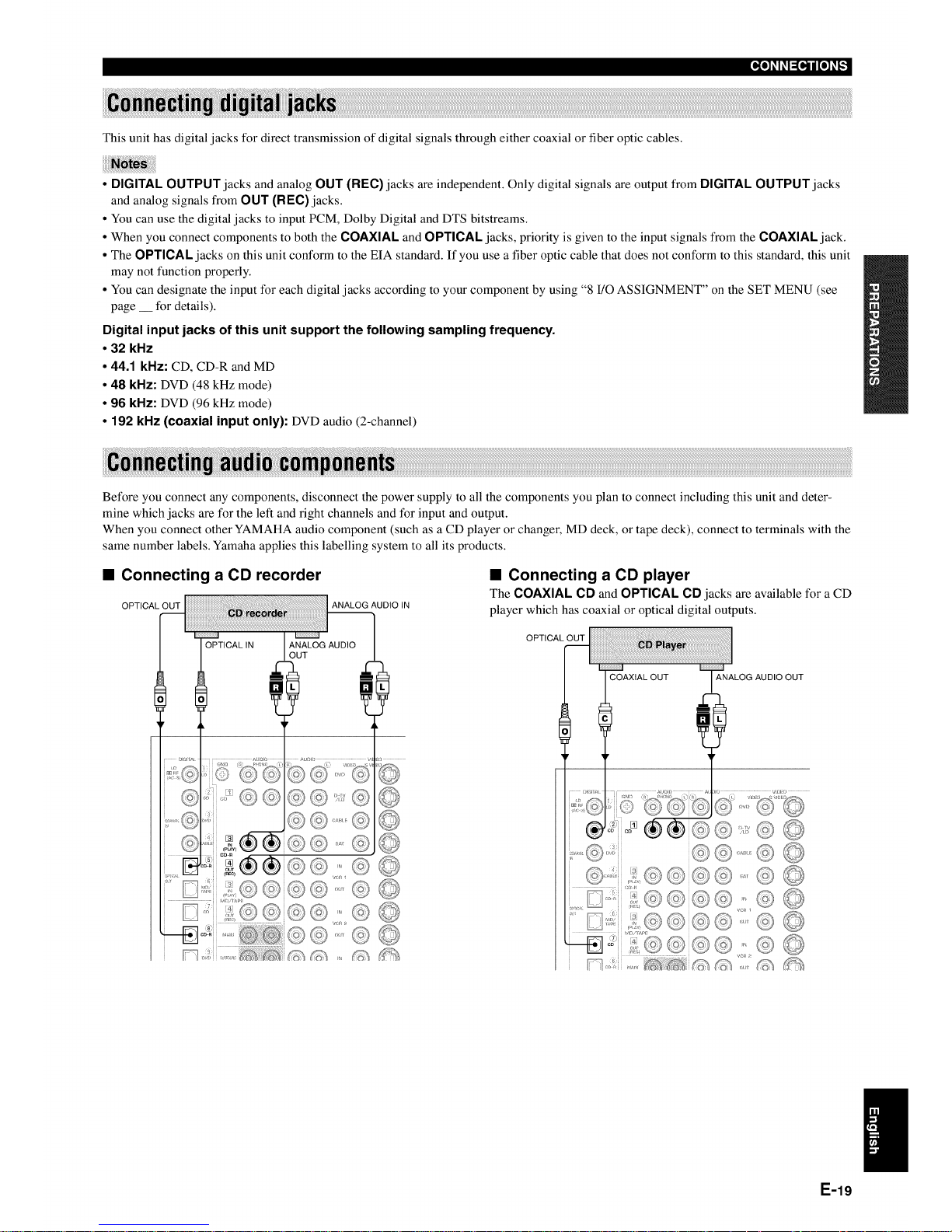
• Connecting a CD recorder
OPTICAL OUT ANALOG AUDIO IN
• Connecting a CD player
The COAXIAL CD and OPTICAL CD jacks are available for a CD
player which has coaxial or optical digital outputs.
OPTICAL OUT
ANALOG AUDIO OUT
E-19
[_o_l_o,._ijI_o_-,."]
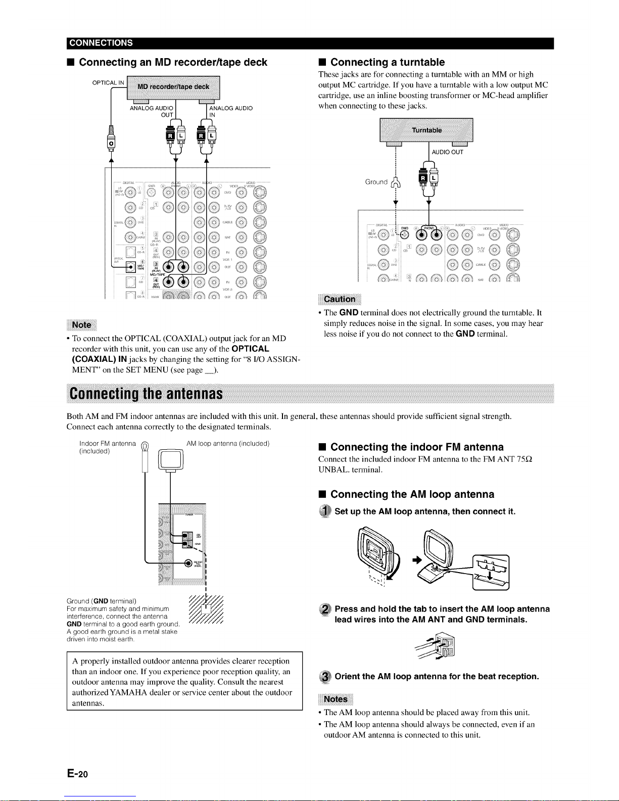
• Connecting an MD recorder/tape deck
OPTICAL IN
ANALOG AUDIO
IN
• Connecting a turntable
These jacks are for connecting a turntable with an MM or high
output MC cartridge. If you have a turntable with a low output MC
cartridge, use an inline boosting transformer or MC-head amplifier
when connecting to these jacks.
• To connect the OPTICAL (COAXIAL) output jack for an MD
recorder with this unit, you can use any of the OPTICAL
(COAXIAL) IN jacks by changing the setting tbr "8 I/O ASSIGN-
MENT" on the SET MENU (see page __).
Ground I_
AUDIO OUT
@,: (:#
• The GND terminal does not electrically ground the turntable. It
simply reduces noise in the signal. In some cases, you may hear
less noise if you do not connect to the GND terminal.
Both AM and FM indoor antennas are included with this unit. In general, these antennas should provide sufficient signal strength.
Connect each antenna correctly to the designated terminals.
Indoor FM antenna
(included)
AM loop antenna (included)
• Connecting the indoor FM antenna
Connect the included indoor FM antenna to the FM ANT 75Q
UNBAL. terminal.
• Connecting the AM loop antenna
_Set up the AM loop antenna, then connect it.
Ground (GND terminaI)
For maximum safety and minimum
interference, connect the antenna
GND terminal to a good earth ground.
A good earth ground is a metal stake
driven into moist earth.
i
_ ress and hold the tab to insert the AM loop antenna
lead wires into the AM ANT and GND terminals.
A properly installed outdoor antenna provides clearer reception
than an indoor one. If you experience poor reception quality, an
outdoor antenna may improve the quality. Consult the nearest
authorized YAMAHA dealer or service center about the outdoor
antennas.
_ Orient the AM loop antenna for the beat reception.
• The AM loop antenna should be placed away from this unit.
• The AM loop antenna should always be connected, even if an
outdoor AM antenna is connected to this unit.
E-20

Before you connect any components, disconnect the power supply to all the components you plan to connect including this unit and deter-
mine which jacks are for the left and right channels and for input and output. After you finish all connections, check them again to make sure
they are correct.
• About the video jacks
There are three types of video jacks.
O Composite VIDEO jack
Video signals input through the VIDEO jacks are the conventional
composite video signals.
0 S VIDEO jack
Video signals input through the S VIDEO jacks are separated into
luminance (Y) and color (C) video signals. The S-video signals
achieve high quality color reproduction. When you are using the S
VIDEO jacks, check the details in the owner's manual that came
with the component being connected.
0 COMPONENT VIDEO jacks
Video signals input through the COMPONENT VIDEO jacks are
separated into luminance (Y) and color difference (PB/CB, PR/CR)
video signals. The jacks are also separated into three for each signal.
The labels of the component video jacks may be different depend-
ing on the component (e.g. Y, CB, CR/Y, PB,PR/Y, B-Y, R-Y/etc.).
Component video signals provide the best quality in picture
reproduction. When you are using the COMPONENT VIDEO
jacks, check the details in the owner's manual that came with the
component being connected.
• Use a commercially available S-video cable when connecting to
the S VIDEO jacks, and commercially available video cables
when connecting to the COMPONENT VIDEO jacks.
• Each type of video jack works independently. Signals input
through the composite video, S-video, and component jacks are
output through the corresponding composite video, S-video, and
component jacks respectively.
• If your video monitor is connected only to the COMPONENT
VIDEO jacks of this unit, the OSD is not shown.
• You can designate the input for the COMPONENT VIDEO A, B
and C jacks according to your component by using "8 I/O
ASSIGNMENT" on the SET MENU (see page __ for details).
E-21
_o_l_o,.]ijI_o]_-,."]
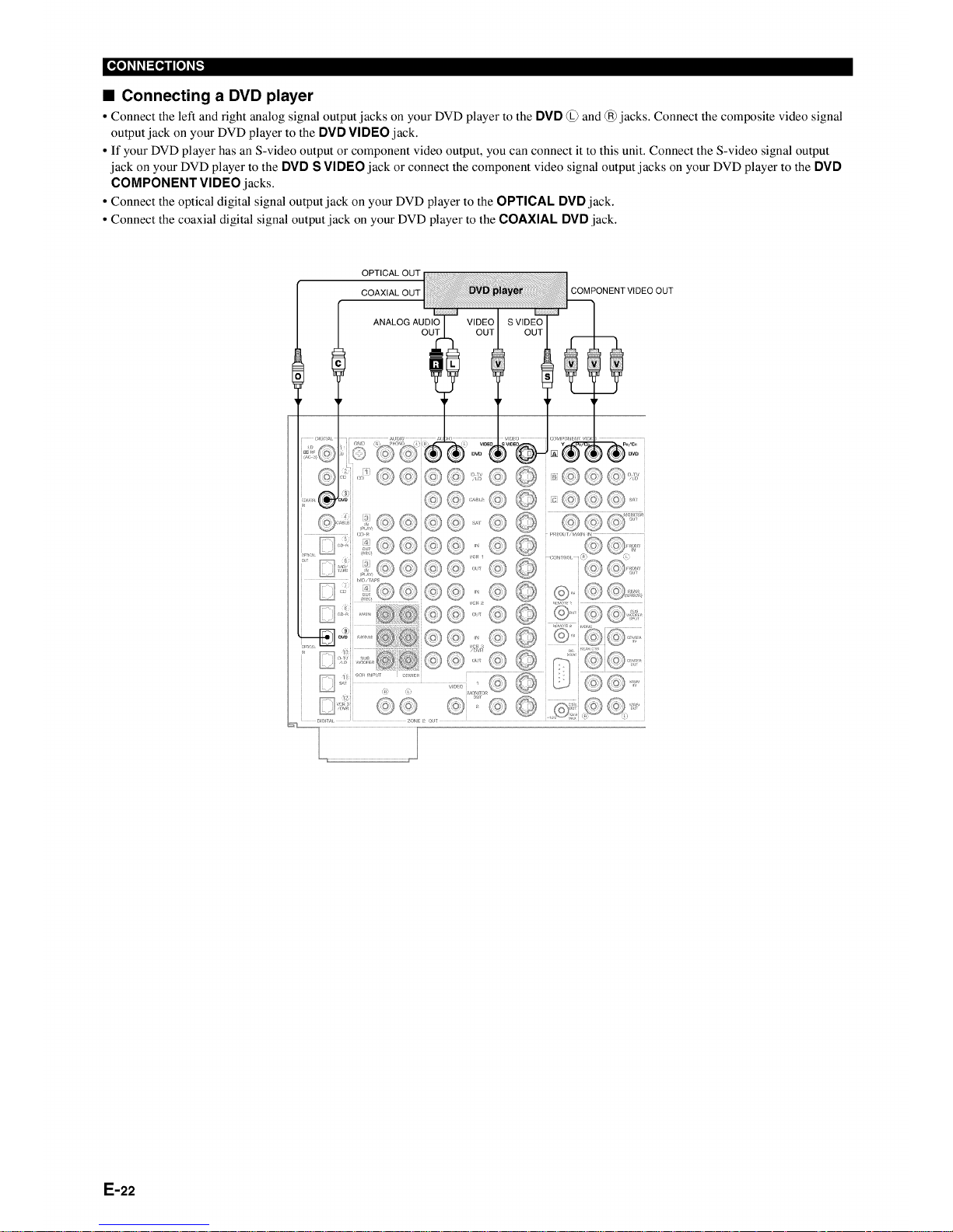
• Connecting a DVD player
• Connect the left and right analog signal output jacks on your DVD player to the DVD @ and @jacks. Connect the composite video signal
output jack on your DVD player to the DVD VIDEO jack.
• If your DVD player has an S-video output or component video output, you can connect it to this unit. Connect the S-video signal output
jack on your DVD player to the DVD S VIDEO jack or connect the component video signal output jacks on your DVD player to the DVD
COMPONENT VIDEO jacks.
• Connect the optical digital signal output jack on your DVD player to the OPTICAL DVD jack.
• Connect the coaxial digital signal output jack on your DVD player to the COAXIAL DVD jack.
COMPONENT VIDEO OUT
ANALOGAUDI_ VIDEO I SVIDEO"_
L !
E-22
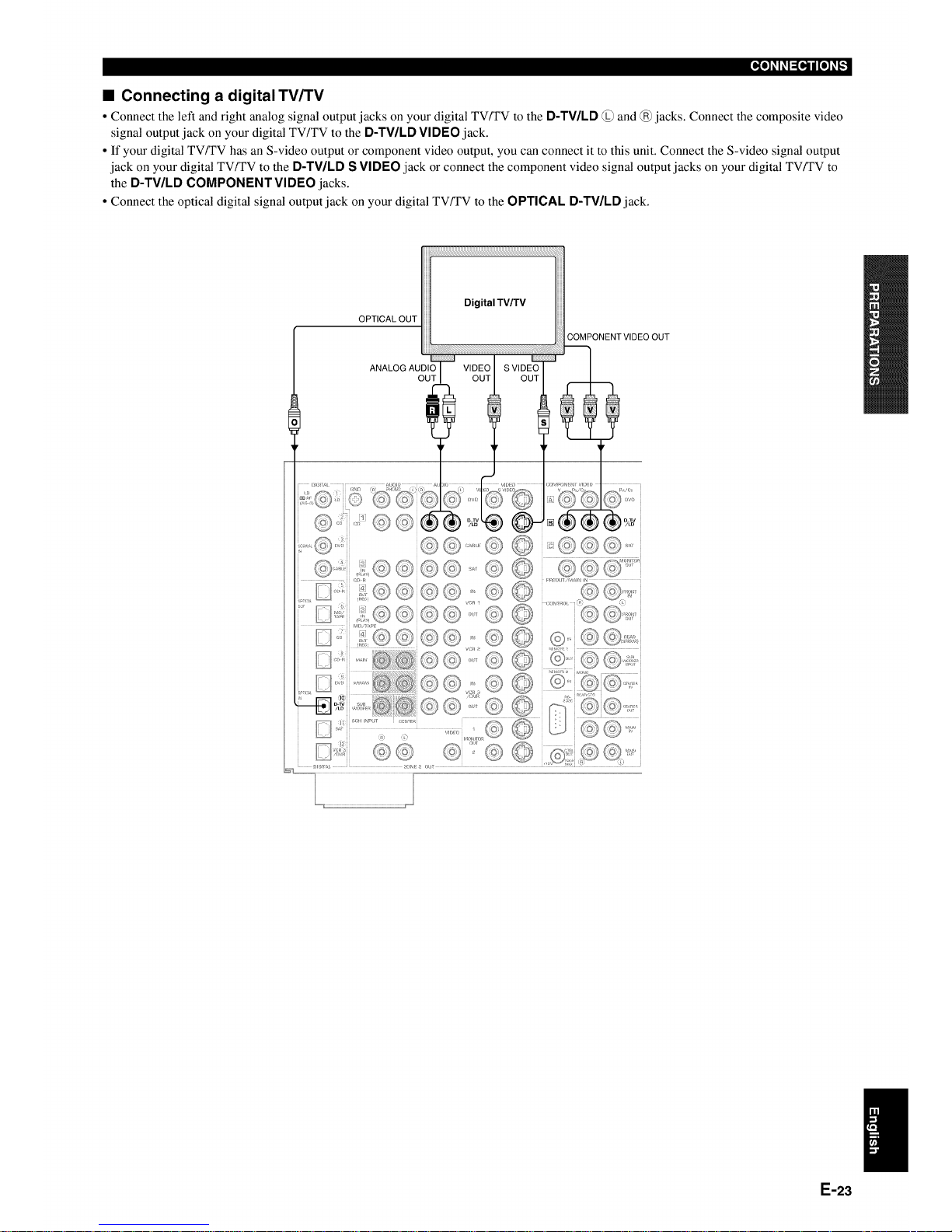
• Connecting a digital TV/TV
• Connect the left and right analog signal output jacks on your digital TVFFV to the D-TV/LD @ and @jacks. Connect the composite video
signal output jack on your digital TV/TV to the D-TV/LD VIDEO jack.
• If your digital TVFFV has an S-video output or component video output, you can connect it to this unit. Connect the S-video signal output
jack on your digital TV/TV to the D-TV/LD S VIDEO jack or connect the component video signal output jacks on your digital TVFFV to
the D-TV/LD COMPONENT VIDEO jacks.
• Connect the optical digital signal output jack on your digital TVFFV to the OPTICAL D-TWLD jack.
OPTICAL OUT
COMPONENT VIDEO OUT
© @
© ©
/
E-23
_o_l_o,._ijI_o_-,."]
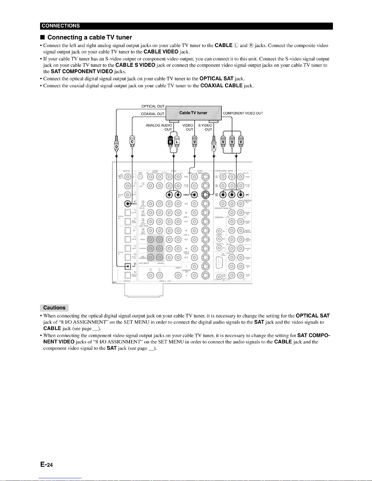
• Connecting a cable TV tuner
• Connect the left and right analog signal output jacks on your cable TV tuner to the CABLE @ and @jacks. Connect the composite video
signal output jack on your cable TV tuner to the CABLE VIDEO jack.
• If your cable TV tuner has an S-video output or component video output, you can connect it to this unit. Connect the S-video signal output
jack on your cable TV tuner to the CABLE S VIDEO jack or connect the component video signal output jacks on your cable TV tuner to
the SAT COMPONENT VIDEO jacks.
• Connect the optical digital signal output jack on your cable TV tuner to the OPTICAL SAT jack.
• Connect the coaxial digital signal output jack on your cable TV tuner to the COAXIAL CABLE jack.
OPTICAL OUT
COAXIAL OUT
ANALOG AUDIO
OUT
©©'©
COMPONENTVIDEO OUT
• When connecting the optical digital signal output jack on your cable TV tuner, it is necessary to change the setting for the OPTICAL SAT
jack of "8 I/O ASSIGNMENT" on the SET MENU in order to connect the digital audio signals to the SAT jack and the video signals to
CAB LE jack (see page __).
• When connecting the component video signal output jacks on your cable TV tuner, it is necessary to change the setting for SAT COMPO-
NENT VIDEO jacks of "8 I/O ASSIGNMENT" on the SET MENU in order to connect the audio signals to the CABLE jack and the
component video signal to the SAT jack (see page __).
E-24
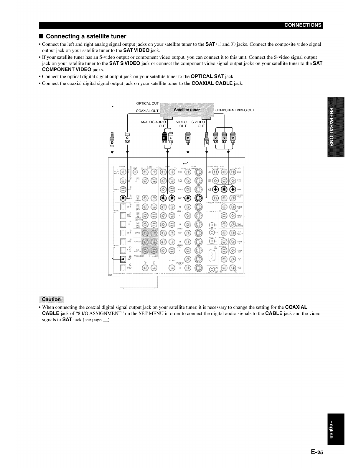
• Connecting a satellite tuner
• Connect the left and right analog signal output jacks on your satellite tuner to the SAT @ and @jacks. Connect the composite video signal
output jack on your satellite tuner to the SAT VIDEO jack.
• If your satellite tuner has an S-video output or component video output, you can connect it to this unit. Connect the S-video signal output
jack on your satellite tuner to the SAT S VIDEO jack or connect the component video signal output jacks on your satellite tuner to the SAT
COMPONENT VIDEO jacks.
• Connect the optical digital signal output jack on your satellite tuner to the OPTICAL SAT jack.
• Connect the coaxial digital signal output jack on your satellite tuner to the COAXIAL CABLE jack.
OPTICAL OUT
COAXIAL OUT
COMPONENTVIDEO OUT
ANALOG AUDIO
OUT
• When connecting the coaxial digital signal output jack on your satellite tuner, it is necessary to change the setting for the COAXIAL
CABLE jack of "8 I/O ASSIGNMENT" on the SET MENU in order to connect the digital audio signals to the CABLE jack and the video
signals to SAT jack (see page __).
E-25
 Loading...