

Page 1

Getting Started Guide
Manuel de l’utilisateur
Guía de introducción
1 2 3 4 5 6 7 8 9
PAD
20dB
20dB
20dB
20dB
20dB
20dB
20dB
20dB
20dB
–16 –60
–16 –60
–16 –60
–16 –60
–16 –60
–16 –60
–16 –60
–16 –60
GAIN
1
SCENE MEMORY
INC +
STORE
DEC –
RECALL
METER
PAN/ø
SEND 1
EQ-LOW
1
SEL
ON
GAIN
GAIN
GAIN
GAIN
2
3
UTILITY
MIDI
GROUP
PAIR
COMP
CUE
2
3
4
MID
HIGH
LIBRARY
2
3
SEL
SEL
ON
ON
GAIN
4
5
6
FUNCTION
MEMORY
SEL CH
4
5
6
SEL
SEL
SEL
ON
ON
ON
–16 –60
GAIN
GAIN
GAIN
7
8
9
7
8
9
SEL
SEL
SEL
ON
ON
ON
Kurzanleitung
10 LRLR
11 12 13 14 15 16
20dB
20dB
20dB
20dB
20dB
20dB
20dB
–16 –60
–16 –60
–16 –60
–16 –60
–16 –60
–16 –60
GAIN
GAIN
GAIN
10
10
SEL
ON
GAIN
11
12
13
RTN 1
RTN 2
SEND 3
SEND 4
11
12
13
SEL
SEL
SEL
ON
ON
ON
–16 –60
GAIN
GAIN
GAIN
14
15
16
ENTER
CLIP
15
12
9
6
3
0
–6
–12
–18
–24
–40
R
L
14
15
16
SEL
SEL
SEL
ON
ON
ON
ST IN
ST IN
SEL
ON
010
LEVEL
MONITOR
OUT
PARAMETER
RTN/
SEND ST OUT
SEL
ON
2TR IN
CUE/ 2TR IN
010
LEVEL
PHONES
SEL
ON
6
6
6
6
6
6
6
6
6
6
6
6
6
6
6
6
6
6
0
0
0
0
0
0
0
0
0
0
0
0
0
0
0
5
5
5
5
5
5
5
5
5
5
5
5
10
10
10
10
10
10
10
10
10
20
20
20
20
20
20
40
40
40
60
00
1
40
60
60
60
00
00
00
2
3
4
20
40
40
40
60
60
60
00
00
00
5
6
7
10
20
20
20
40
40
40
60
60
60
00
00
00
8
9
10
5
10
10
10
20
20
20
40
40
40
60
60
60
00
00
00
11
12
13
0
5
5
5
10
10
10
20
20
20
40
40
40
60
60
60
00
00
00
14
15
16
6
0
0
0
5
5
5
10
10
10
20
20
20
40
40
40
60
60
60
00
00
00
RTN/
ST IN
ST OUT
SEND
Page 2

FCC INFORMATION (U.S.A.)
1. IMPORTANT NOTICE: DO NOT MODIFY THIS UNIT!
This product, when installed as indicated in the instructions contained in this manual, meets FCC requirements. Modifications not expressly approved by
Yamaha may void your authority, granted by the FCC, to use the product.
2. IMPORTANT: When connecting this product to accessories and/or another product use only high quality shielded cables. Cable/s supplied with this product
MUST be used. Follow all installation instructions. Failure to follow instructions could void your FCC authorization to use this product in the USA.
3. NOTE: This product has been tested and found to comply with the requirements listed in FCC Regulations, Part 15 for Class “B” digital devices. Compliance
with these requirements provides a reasonable level of assurance that your use of this product in a residential environment will not result in harmful interference
with other electronic devices. This equipment generates/uses radio frequencies and, if not installed and used according to the instructions found in the users
manual, may cause interference harmful to the operation of other electronic devices. Compliance with FCC regulations does not guarantee that interference
will not occur in all installations. If this product is found to be the source of interference, which can be determined by turning the unit “OFF” and “ON”, please
try to eliminate the problem by using one of the following measures:
Relocate either this product or the device that is being affected by the interference
Utilize power outlets that are on different branch (circuit breaker of fuse) circuits or install AC line filter/s.
In the case of radio or TV interference, relocate/reorient the antenna. If the antenna lead-in is 300 ohm ribbon lead, change the lead-in to coaxial type cable.
If these corrective measures do not produce satisfactory results, please contact the local retailer authorized to distribute this type of product. If you can not locate
the appropriate retailer, please contact Yamaha Corporation of America. Electronic Service Division, 6600 Orangethorpe Ave, Buena Park, CA 90620
This applies only to products distributed by YAMAHA CORPORATION OF AMERICA
*
Dette apparat overholder det gaeldende EF-direktiv vedtrørende
radiostøj.
Cet appareil est conforme aux prescriptions de la directive
communautaire 87/308/CEE.
Diese Geräte entsprechen der EG-Richtlinie 82/499/EWG und/
oder 87/308/EWG.
This product complies with the radio frequency interference requirements of the Council Directive 82/499/EEC and/or 87/308/
EEC.
Questo apparecchio è conforme al D.M.13 aprile 1989 (Direttiva
CEE/87/308) sulla soppressione dei radiodisturbi.
Este producto está de acuerdo con los requisitos sobre interferencias
de radio frequencia fijados por el Consejo Directivo 87/308/CEE.
YAMAHA CORPORATION
IMPORTANT NOTICE FOR
THE UNITED KINGDOM
Connecting the Plug and Cord
WARNING: THIS APPARATUS MUST BE EARTHED
IMPORTANT: The wires in this mains lead are coloured in accordance with
the following code:
GREEN-AND-YELLOW : EARTH
BLUE : NEUTRAL
BROWN :LIVE
As the colours of the wires in the mains lead of this apparatus may not
correspond with the coloured markings idenlifying the terminals in your
plug, proceed as follows:
The wire which is coloured GREEN and YELLOW must be connected to the
terminal in the plug which is marked by the letter E or by the safety earth
symbol or coloured GREEN and YELLOW.
The wire which is coloured BLUE must be connected to the terminal which
is marked with the letter N or coloured BLACK.
The wire which is coloured BROWN must be connected to the terminal
which is marked with the letter L or coloured RED.
This applies only to products distributed by YAMAHA KEMBLE MUSIC (U.K.)
*
LTD.
CANADA
THIS DIGITAL APPARATUS DOES NOT EXCEED THE “CLASS
B” LIMITS FOR RADIO NOISE EMISSIONS
FROM DIGITAL APPARATUS SET OUT IN THE RADIO INTERFERENCE REGULATION OF THE CANADIAN DEPARTMENT
OF COMMUNICATIONS.
LE PRESENT APPAREIL NUMERIQUE N’EMET PAS DE BRUITS
RADIOELECTRIQUES DEPASSANT LES LIMITES APPLICABLES
AUX APPAREILS NUMERIQUES DE LA “CLASSE B”
PRESCRITES DANS LE REGLEMENT SUR LE BROUILLAGE
RADIOELECTRIQUE EDICTE PAR LE MINISTERE DES COMMUNICATIONS DU CANADA.
This applies only to products distributed by YAMAHA CANADA
*
MUSIC LTD.
Litiumbatter!
Bör endast bytas av servicepersonal.
Explosionsfara vid felaktig hantering.
VAROITUS!
Lithiumparisto, Räjähdysvaara.
Pariston saa vaihtaa ainoastaan aian
ammattimies.
ADVARSELl!
Lithiumbatter!
Eksplosionsfare. Udskiftning må kun foretages
af en sagkyndig, –og som beskrevet i
servicemanualen.
Page 3

i
Important Information
Please read the following before operating ProMix 01.
Safety Information
• Make sure the P roMix 01 power cord is not locat ed in a position
where it is likely to be walked on or pinc hed b y other equipment.
• Make sure ProMix 01 is earthed correctly.
• Do not expose ProMix 01 to direct sunlight, extremes of temperature or humidity, excessive dust or vibration, or severe shocks.
• The ambient temperature where ProMix 01 is sited should be
between 10˚C and 35˚C (50˚F and 95˚F).
Warnings
• ProMix 01 should be connected only to an AC receptacle of the
type described in this User’s Guide or as marked on ProMix 01.
• To reduce the risk of electric shock, do not open ProMix 01.
• To reduce the risk of fire or electric shock, do not expose
ProMix 01 to rain or moisture.
• In an extremely humid environment, condensation ma y form on
the inside and outside of ProMix 01. If condensation does occur,
leave ProMix 01 powered on, but do not use it until the condensation has cleared.
• ProMix 01 contains no user serviceable parts. Refer all servicing
to qualified personnel.
• ProMix 01 uses high frequency digital circuits. When used close
to TV and radio equipment, interference may occur . If this is the
case, simply relocate ProMix 01 or the affected equipment.
• If any of the following should occur, ProMix 01 should be serviced
by qualified personnel:
The ProMix 01 power cord or plug becomes damaged in any way.
Metal objects or liquids get inside ProMix 01.
ProMix 01 is exposed to rain.
ProMix 01 is dropped, the enclosure damaged, or both.
ProMix 01 does not operate normally or a marked change in per-
formance is noticed.
ProMix 01 Getting Started Guide
Page 4

•
ii
Copyright
© 1994 Yamaha Corporation. All rights reserved.
No part of the ProMix 01 software or its user manuals may be repro-
duced or distributed in any form or by any means without the prior
written authorization of Yamaha Corporation.
Trademarks
All trademarks are the property of their respective holders.
Cable Notes
ProMix 01 offers superb sonic quality. So the last thing you want is
signal degradation due to cheap or corroded connectors. It ’s usually
better to buy the best connecting cables that y ou can afford. And don ’t
forget to keep them clean using a quality contact cleaner.
Interference
Under rare circumstances, CH9-16 may pick up radio or TV interference when used with unbalanced connectors. Therefore, we recommend that you use balanced connectors wherever possible.
ProMix 01 Cleaning
If ProMix 01 should require cleaning, use a soft, lightly moistened
cloth. Stubborn marks can be removed using a mild det ergent. Do not
use abrasive cleaners or solvent based cleaning fluids such as alc ohol
and benzine.
Unpacking
At approximately 12.5 kg (27.6 lb), ProMix 01 is a relative heavyweight, so it’s a good idea to get someone to help you unpack it. You
may want to keep the packaging materials for future use.
Package Contents
Your ProMix 01 package contains the following items. If you do not
have them all, please contact your Yamaha dealer.
ProMix 01 Getting Started Guide
• ProMix 01
• This Getting Started Guide
User’s Guide
• Button Protector (for ST OUT [ON] button)
Page 5

iii
Contents
1 Welcome to ProMix 01 . . . . . . . . . . . . 1
Welcome to ProMix 01 . . . . . . . . . . . . . . . . . . . . . . . . . . . . 2
ProMix 01 User Guides . . . . . . . . . . . . . . . . . . . . . . . . . . . . 2
Installation . . . . . . . . . . . . . . . . . . . . . . . . . . . . . . . . . . . . . . . 2
Top & Rear . . . . . . . . . . . . . . . . . . . . . . . . . . . . . . . . . . . . . . 3
ProMix 01 Sonic Spec . . . . . . . . . . . . . . . . . . . . . . . . . . . . . . 4
ProMix 01 General Features . . . . . . . . . . . . . . . . . . . . . . . . 4
ProMix 01 Key Features . . . . . . . . . . . . . . . . . . . . . . . . . . . . 5
ProMix 01 Secrets . . . . . . . . . . . . . . . . . . . . . . . . . . . . . . . . . 8
2 Getting Started . . . . . . . . . . . . . . . . . . 9
What You’ll Need . . . . . . . . . . . . . . . . . . . . . . . . . . . . . . . 10
Basic Setup . . . . . . . . . . . . . . . . . . . . . . . . . . . . . . . . . . . . . 10
Making the Connections . . . . . . . . . . . . . . . . . . . . . . . . . 11
Power ON/OFF . . . . . . . . . . . . . . . . . . . . . . . . . . . . . . . . . 11
3 Basic Mixing Tutorial . . . . . . . . . . . . 13
Setting the Input Level . . . . . . . . . . . . . . . . . . . . . . . . . . . 14
Applying EQ . . . . . . . . . . . . . . . . . . . . . . . . . . . . . . . . . . . 15
Using the EQ Library . . . . . . . . . . . . . . . . . . . . . . . . . . . . 18
CUE LCD Function . . . . . . . . . . . . . . . . . . . . . . . . . . . . . 20
Setting the CUE Mode . . . . . . . . . . . . . . . . . . . . . . . . . . . 21
Setting Fader Levels . . . . . . . . . . . . . . . . . . . . . . . . . . . . . 21
Channel ON/OFF . . . . . . . . . . . . . . . . . . . . . . . . . . . . . . . 22
Panning . . . . . . . . . . . . . . . . . . . . . . . . . . . . . . . . . . . . . . . 22
4 Advanced Mixing Tutorial . . . . . . . . 23
Applying Effects . . . . . . . . . . . . . . . . . . . . . . . . . . . . . . . . 24
Recalling Effects . . . . . . . . . . . . . . . . . . . . . . . . . . . . . . . . 24
Editing Effects . . . . . . . . . . . . . . . . . . . . . . . . . . . . . . . . . . 25
Storing User Effects . . . . . . . . . . . . . . . . . . . . . . . . . . . . . . 26
Patching in a Compressor . . . . . . . . . . . . . . . . . . . . . . . . 27
Storing Mix Scenes . . . . . . . . . . . . . . . . . . . . . . . . . . . . . . 28
Recalling Mix Scenes . . . . . . . . . . . . . . . . . . . . . . . . . . . . . 29
Where to Go from Here? . . . . . . . . . . . . . . . . . . . . . . . . . 30
5 Application Examples . . . . . . . . . . . . 31
Live Performance . . . . . . . . . . . . . . . . . . . . . . . . . . . . . . . 32
Onstage Keyboard Mixing . . . . . . . . . . . . . . . . . . . . . . . . 34
MIDI Studio . . . . . . . . . . . . . . . . . . . . . . . . . . . . . . . . . . . 36
Multitracking . . . . . . . . . . . . . . . . . . . . . . . . . . . . . . . . . . . 38
ProMix 01 Getting Started Guide
Page 6

iv
6 Mixing and Automation . . . . . . . . . . 41
General Mix Procedure . . . . . . . . . . . . . . . . . . . . . . . . . . . 42
What is ProMix 01 Automation . . . . . . . . . . . . . . . . . . . . 45
An Automation System . . . . . . . . . . . . . . . . . . . . . . . . . . . 45
Mix Scenes & Automation . . . . . . . . . . . . . . . . . . . . . . . . . 46
Real-Time Automation . . . . . . . . . . . . . . . . . . . . . . . . . . . 47
ProMix 01 Getting Started Guide
Page 7

1
Welcome to ProMix 01
Welcome to ProMix 01
In this chapter...
Welcome to ProMix 01 . . . . . . . . . . . . . . . . . . . . . . . . . 2
1
ProMix 01 User Guides . . . . . . . . . . . . . . . . . . . . . . . . . 2
Installation . . . . . . . . . . . . . . . . . . . . . . . . . . . . . . . . . . . 2
Top & Rear . . . . . . . . . . . . . . . . . . . . . . . . . . . . . . . . . . . 3
ProMix 01 Sonic Spec . . . . . . . . . . . . . . . . . . . . . . . . . . 5
ProMix 01 General Features . . . . . . . . . . . . . . . . . . . . . 5
ProMix 01 Key Features . . . . . . . . . . . . . . . . . . . . . . . . . 6
ProMix 01 Secrets . . . . . . . . . . . . . . . . . . . . . . . . . . . . . 9
ProMix 01 Getting Started Guide
Page 8

Chapter 1: Welcome to ProMix 01
2
Welcome to ProMix 01
Thank you for purchasing and welcome t o—ProMix 01—the world’ s
first affordable programmable digital mixer. With superb sonic performance, full MIDI control, and a powerful feature set, ProMix 01
is a mixer for life—whatever your application—be it keyboard mixing, MIDI studio, live sound, commercial installation, sub-mixer,
theater, post production, hard disk recording, and so on.
ProMix 01 User Guides
ProMix 01 is supplied with two user guides. This Getting Started
Guide
and a
User’s Guide
tutorials to get you started. The
explains all ProMix 01 functions in full detail. Use the table of contents to search for general topics and the index to sear ch for specifics.
A glossary of ProMix 01 related jargon is provided.
. This
Getting Started Guide
User’s Guide
contains two
, on the other hand,
This guy is your resident ProMix 01 expert. He’ll introduce you to
ꎹ
each tutorial section and monitor your progress on his headset. Since
printed paper is a non-interactive medium, however, he can’t help
you out if you get stuck. Still, the tutorials are relatively straightforward, so you shouldn’t have any problems.
We recommend that you start with this Getting Started Guide , and
then move on to the User’s Guide when you are little more familiar
with ProMix 01. You may want to refer to the
detailed information while using this guide.
In both guides, parameter range values are separated by a dash, for
example: 0–100%. Where the range consists of plus and minus values,
however , they are separated by thr ee periods, for example: –99...+99.
This is to avoid possible co nfusion between the minus sign and dash.
User’s Guide
Installation
Site ProMix 01 on a stable surface. Somewhere that complies with the
“Important Information” on page i. The motorized faders don’t
mind climbing hills, so ProMix 01 can be positioned at a sloping
angle. ProMix 01 can also be rack mounted using the optional
rack-mount kit. Optional wooden side panels can be fitted for an even
more attractive finish. I f you plan to tak e P r oMix 01 on the road, an
optional carrying case is available. A set of color fader knobs is also
available. See your Yamaha dealer for details.
for more
ProMix 01 Getting Started Guide
Page 9
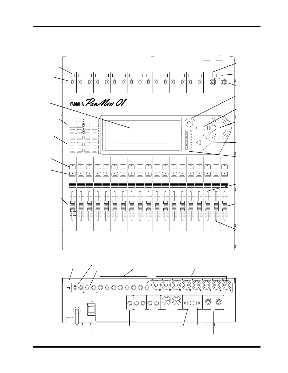
20dB PAD switch
GAIN control
LCD
SCENE MEMORY
buttons
LCD function
buttons
SEL button
ON button
Top & Rear
1 2 3 4 5 6 7 8 9
PAD
20dB
20dB
20dB
20dB
20dB
20dB
20dB
20dB
20dB
–16 –60
–16 –60
–16 –60
–16 –60
–16 –60
–16 –60
–16 –60
–16 –60
GAIN
GAIN
1
SCENE MEMORY
INC +
STORE
DEC –
RECALL
METER
PAN/ø
SEND 1
EQ LOW
MID
1
SEL
ON
GAIN
GAIN
GAIN
GAIN
FUNCTION
MEMORY
SEL CH
GAIN
6
7
6
7
SEL
SEL
ON
ON
2
3
4
5
UTILITY
MIDI
GROUP
PAIR
COMP
CUE
2
3
4
HIGH
LIBRARY
2
3
4
SEL
SEL
ON
ON
5
SEL
SEL
ON
ON
–16 –60
GAIN
GAIN
8
9
8
9
SEL
SEL
ON
ON
11 12 13 14 15 16
10 LRLR
20dB
20dB
20dB
20dB
20dB
20dB
20dB
–16 –60
–16 –60
–16 –60
–16 –60
–16 –60
–16 –60
GAIN
GAIN
GAIN
GAIN
10
11
12
GAIN
13
14
–16 –60
GAIN
GAIN
15
16
ENTER
RTN 1
RTN 2
SEND 3
SEND 4
10
11
12
SEL
SEL
ON
ON
13
SEL
SEL
ON
ON
CLIP
15
12
9
6
3
0
–6
–12
–18
–24
–40
R
L
14
15
SEL
ON
16
SEL
SEL
ON
ON
ST IN
ST IN
SEL
ON
CUE/ 2TR IN
010
LEVEL
MONITOR
OUT
PARAMETER
RTN/
SEND ST OUT
SEL
ON
Top & Rear
2TR IN
010
LEVEL
PHONES
SEL
ON
3
MONITOR OUT
LEVEL control
CUE/2TR IN
switch
PHONES
LEVELcontrol
LCD contrast
control
ENTER button
PARAMETER
wheel
Cursor buttons
Stereo output
L/R meters
Input channel fader
6
6
0
0
5
5
10
10
20
20
40
40
60
60
00
00
1
2
Phantom power
master switch
PHANTOM
MASTER
CH1~8
–10dB
ON OFF
(UNBAL)
(+48V)
R
L
2TR IN
6
6
0
0
5
5
10
10
20
20
40
40
60
60
00
00
3
4
2-track input jacks
Stereo input jacks
+4dB
(UNBAL)
R
L
16 15
ST IN
POWER
ON
OFF
Stereo input
fader
6
6
6
6
6
6
6
6
6
6
6
6
6
6
6
0
0
0
0
0
0
0
0
0
0
0
0
0
0
5
5
5
5
5
5
5
5
5
5
5
5
10
10
10
10
10
10
10
10
10
10
20
20
20
20
20
20
20
20
40
40
40
40
40
40
60
60
60
60
00
00
00
5
6
60
00
00
7
8
40
60
60
00
00
9
10
11
20
40
40
60
60
00
00
12
13
10
20
20
40
40
60
60
00
00
14
15
Input channels 9–16
balanced input jacks
14 13
12 11
PHONES
10
+4dB
(UNBAL)
R
MONITOR OUT
9
+4dB
(UNBAL)
L4
8
INPUT
3R
7
(BAL)
+4dB (BAL)
STEREO OUTAUX SEND
65
ANALOG DIGITAL
–10dB
(UNBAL)
L
RL
REC OUT MIDI
5
10
10
20
20
40
40
60
60
00
00
16
ST IN
Input channels 1–8
balanced input XLRs
3
4
COAXIAL
OUT IN
0
5
5
10
10
20
20
40
40
60
60
00
00
RTN/
ST OUT
SEND
21
Stereo output
fader
RTN/SEND
fader
POWER switch
PHONES
output jack
MONITOR OUT
jacks
AUX SEND
output jacks
Analog
REC OUT
STEREO OUT
XLRs
Digital
REC OUT
MIDI IN/OUT
ProMix 01 Getting Started Guide
Page 10

Chapter 1: Welcome to ProMix 01
4
ProMix 01 Sonic Spec
• Linear 20-bit 64-times oversampling A/D co nv erters (CH, ST IN)
• Linear 20-bit 8-times oversampling D/A converters (ST OUT)
• 105dB dynamic range (typical)
• Frequency response of 20Hz–20kHz +1, –3dB
ProMix 01 General Features
• 16 input channels (eight XLR, eight phone jack—all balanced)
• Continuously variable gain control
• 20dB input pad
• 48V phantom power for condenser microphones
• Stereo input channel
• Balanced XLR stereo outputs
• 50 scene memories for storing mix scenes
• Two internal effects processors with 30 preset, 10 user programs
• Three dynamics processors with 10 preset, 10 user programs
• Fully parametric three-band EQ
• EQ library with 30 preset, 20 user programs
• Four fader groups for single fader control of several faders
• Adjacent channel Pair function for stereo operation
• Full MIDI control
• CUE for virtually all inputs and outputs
• Four auxiliary sends: two for internal effects, two for ext ernal use
• 60 mm motorized faders
• 33-position pan controls
• Large 240 x 64 dot backlit LCD display
• Stereo 12-segment LED meters
• Digital two-track OUT
• Analog two-track IN/OUT
ProMix 01 Getting Started Guide
• Optional rack-mount kit, carrying case, wooden side panels, and
color fader knob set
Page 11

ProMix 01 Key Features
ProMix 01 Key Features
This section looks at some ProMix 01 key features; what they mean
to you and how you can take advantage of them.
Scene Memories
Until now , the only way t o store mix settings was with marker pen and
masking tape. ProMix 01 scene memories, however, change all that.
They allow you to recall all mix settings (i.e. a mix scene) instantly
with just one press of a button, or MIDI Program Change command.
And it’ s not just mutes and faders, it’s
on several projects at a time, you can store the current mix scene so
when you return to that project, y ou can start again right where you
left off. Scene memories also make light work of night-after-night
sound checks. Simply press r ecall to return to the previous night’s mix
settings. For theater w ork, scene memories allow accurate and re peatable sound changes between scenes. ProMix 01 has 50 scene
memories.
all
mix settings. So if you work
5
MIDI Control
As well as sonic benefits, digital audio systems also hav e excellent control capabilities. In fact, the true pow er of ProMix 01 can be realized
through MIDI control. Simply connecting ProMix 01 to a MIDI
sequencer provides total mix control. Allowing you to list en t o your
mix while difficult moves are performed for you, repeat edly and precisely. MIDI Program Change messages can be used to recall mix
scenes, providing
Change messages can be used to control virtually all mix parameters
in real time, providing
snapshot
dynamic
mix automation. And MIDI Control
mix automation.
Large LCD
At the heart of the ProMix 01 user interface is a large backlit 240 x 64
dot graphic LCD display. This provides clear indication of mix settings and operating status. As well as showing parameter values
numerically, faders and rotary controls are represented graphically , so
you can actually see pan positions and fader positions. In addition,
EQ curves are displayed graphically, a feature certainly not available
on analog mixers. S ignal levels of virtually all inputs and outputs are
metered on the LCD, with peak hold function.
ProMix 01 Getting Started Guide
Page 12

Chapter 1: Welcome to ProMix 01
6
Digital Benefits
You’re probably already familiar with the many benefits of digital
audio, but what e xactly are the benefits for digital audio mixing? W ell,
an audio mixer has the job of combining audio signals from various
sources, at differing levels and impedances, usually into a stereo signal. And it m ust do this without introducing any new distortions and
noise. Analog mixers do a pretty good job, but even with the best
designs nonlinear effects caused by circuit components are
unavoidable.
In the digital realm, audio mixing consists of adding and multiplying
binary numbers that represent audio signals. The DSP (Digital Signal
Processor) chips used for these calculations never get their sums
wrong. So once past the A/D conversion, audio signals are immune
from signal degradation. With ProMix 01, noise, distortion, and
crosstalk are virtually eliminated. You’ll hear a new clarity in your
mixes.
Once in the digital realm, there’s little point converting back to analog. ProMix 01 featur es an S/PDIF digital output for direct mixdown
to DAT and other digital recorders.
ProMix 01 Sonic Performance
ProMix 01’s linear 20-bit 64-times oversampling A/D converters provide a dynamic range of 105dB (typical). This means that an audio
program’ s dynamic range, fr om low to high levels, is proc essed intact.
ProMix 01 samples audio at 48kHz, the professional sampling rate.
This provides a full spectrum frequency response of 20Hz–20kHz +1,
–3dB. Fo r D/A c onversion, the st er eo outputs feature 20-bit 8-times
oversampling and the monitor outputs, 18-bit 8-times oversampling.
Oversampling and bitstream techniques effectively incr ease the internal sampling rate, so side effects caused by steep LPF filters, which are
used to filter out sampling frequency components during D/A conversion, are virtually eliminated. Consequently, audio signal integrity
is maintained from input through to output.
ProMix 01 Getting Started Guide
Page 13

ProMix 01 Key Features
Internal Effects
ProMix 01 features two stereo internal multi-effects processors. A
whole range of effects from reverbs to modulation effects are provided. Effects processors are fed via SEND1 and SEND2, and the processed signals are returned via RTN1 and R TN2, r espectively . Having
internal effects processors means that you don’t have to purchase
external units, effect patching is greatly simplified, and your audio
data remains in the digital realm. Effects settings are stored in mix
scenes and can be controlled in real time. Effects are organized into
programs and there are 30 preset effects programs and 10 user effects
programs for you to store your o wn settings. Your favorite effects processors can be patched into SEND3 and SEND4.
Dynamics Processors
ProMix 01 features three stereo dynamics processors, which can be
assigned to input channels, aux sends, and stereo outputs for compression, limiting, gating, and ducking. The benefits of internal
dynamics processors are similar to those for the int ernal effects. They
are, you don ’t ha ve to purchase ext ernal units, patching is greatly simplified, and your audio data remains in the digital realm. Dynamic
processor settings are stored in mix scenes and can be controlled in
real time. Pr ocessors are organized into programs. Ther e are 10 preset
programs and 10 user programs for you to store your own settings.
7
EQ with Library
ProMix 01 input channels, the stereo input channel, RTN1, RTN2,
and the stereo outputs all feature three-band fully parametric EQ. EQ
parameters consist of gain, frequency, and Q, which is specified in
octaves. From a musical point of view, octa ves are more intuitive than
decimal values. EQ parameter settings are stored in mix scenes and
can be controlled in real time. A library of unique EQ preset programs
designed for specific applications and instruments is provided. There
are 30 preset EQ programs and 20 user EQ programs for you to store
your own settings. The preset EQ programs serve as a good starting
point and reference when making EQ adjustments.
Motorized Faders
ProMix 01 features motorized faders. This means that they can position themselves automatically when mix scenes are recalled. When
real-time automation with a controlling computer or MIDI
sequencer is used, fader mov ements ar e r epla yed aut omatically. Faders can also be grouped into one of four groups for multiple fader control from a single fader . And when adjacent input c hannels are paired,
both channel faders move together.
ProMix 01 Getting Started Guide
Page 14

Chapter 1: Welcome to ProMix 01
8
ProMix 01 Secrets
The following points will help you take full advantage of ProMix 01.
• Besides the DIGITAL REC OUT, inputs and outputs are analog.
• The input channel INPUTs and STEREO OUT are balanced. All
other inputs and outputs are unbalanced.
• On the P AN L CD function, ST OUT is a balance contr ol, not pan.
• When no plugs are inserted into the ST IN phone jacks, the 2TR
IN signals are fed through to the stereo input channel. This is in
addition to being fed through to the CUE/2TR IN switch. This
means that you can apply EQ, etc., to the 2TR IN signals. When
plugs are inserted into the ST IN phone jacks, however, this connection is broken.
• When SEND3 and SEND4 are configur ed as a stereo pair , an additional pan control is available on each input channel and a balanc e
control on the stereo input channel. These extra controls appear
on the SEND3-4 LCD function. In addition, a SEND3-4 output
balance control appears on the PAN LCD function. SEND3 and
SEND4 are configured as a stereo pair using the MASTER CONFIGURATION LCD function in the UTILITY menu.
• If you press the [UTILITY] or [MIDI] button and an LCD function appears instead of a menu, press again to get the menu.
• When the GROUP LCD function is selected, a post-fader mix of
the channels in the selected group can be monitored via CUE
(CUE mode must be MIX or LAST CUE, not ST FIX).
• CH refers to input channels.
• ST IN is the stereo input channel.
• ST OUT is the main stereo output.
• SEND1, SEND2, SEND3, and SEND4 are the four auxiliary sends.
• RTN1 and RTN2 are the two auxiliary returns.
• Effect1 and Effect2 are the internal effects processors.
• COMP1, COMP2, and COMP3 are the dynamics processors. In
the ProMix 01 User G uides they are mainly referred to as d ynamics processors, since they offer more than just compression.
ProMix 01 Getting Started Guide
Page 15

2
Getting Started
Getting Started
In this chapter...
What You’ll Need . . . . . . . . . . . . . . . . . . . . . . . . . . . . . 10
9
Basic Setup . . . . . . . . . . . . . . . . . . . . . . . . . . . . . . . . . . 10
Making the Connections . . . . . . . . . . . . . . . . . . . . . . . 11
Power ON/OFF . . . . . . . . . . . . . . . . . . . . . . . . . . . . . . 11
ProMix 01 Getting Started Guide
Page 16

Chapter 2: Getting Started
10
What You’ll Need
To perform the following tutorials, you need:
• ProMix 01
• A sound source: CD playe r , drum machine, synth with demo song
• An amplifier and speakers, or headphones
• Audio connecting cables
Basic Setup
The following illustration shows how to set up a minimal system that
will allow you to perform the following tutorials.
CD player
INPUTS 9 & 10
Power amp
MONITOR
OUT
To AC receptacle
ProMix 01 Getting Started Guide
Page 17

Making the Connections
11
Making the Connections
Warning: Before making any connections, make sure that all your
equipment is powered OFF.
1. Connect your sound source to input channel 9.
It seems more logical to connect to input channel 1. But sinc e inputs
1 through 8 use XLR-type connectors, and it’s doubtful whether
you’re going to yell into a microphone for both tutorials, we’ll use
input channel 9. If you’re using a stereo sound source, connect to
input channel 10 as well. A stereo source is not essential, and for most
of the tutorial it’s probably easier to work with just one channel.
2. Connect the MONITOR OUTs to your power amplifier’ s inputs.
If you’re using headphones, connect them to the PHONES jack.
3. Plug ProMix 01 into a suitable AC receptacle.
Warning: ProMix 01 should be connected only to an AC receptacle of
the voltage type marked on its rear panel.
POWER
ON
OFF
Power ON/OFF
This section explains how to power ProMix 01 ON and OFF.
Power ON
Always power on your system in the following order: signal source
devices through to power amplifier.
Press the PO WER switch on the rear panel t o pow er ON Pr oMix 01.
The ProMix 01 start-up screen appears for a few seconds, the faders
initialize themselves, then the scr een that was used when P r oM ix 01
was last powered off appears.
Power OFF
Always power off your system in the follo wing order: power amplifier
through to signal source devices.
Press the PO WER switch on the rear panel to pow er OFF ProMix 01.
All mix settings, mix scenes, and other data is stored when ProMix 01
is powered OFF.
ProMix 01 Getting Started Guide
Page 18

Chapter 2: Getting Started
12
ProMix 01 Getting Started Guide
Page 19

3
Basic Mixing Tutorial
Basic Mixing Tutorial
In this chapter...
Setting the Input Level . . . . . . . . . . . . . . . . . . . . . . . . . 14
13
ꎹ
Applying EQ . . . . . . . . . . . . . . . . . . . . . . . . . . . . . . . . . 15
Using the EQ Library . . . . . . . . . . . . . . . . . . . . . . . . . . 18
CUE LCD Function . . . . . . . . . . . . . . . . . . . . . . . . . . . 20
Setting the CUE Mode . . . . . . . . . . . . . . . . . . . . . . . . . 21
Setting Fader Levels . . . . . . . . . . . . . . . . . . . . . . . . . . . 21
Channel ON/OFF . . . . . . . . . . . . . . . . . . . . . . . . . . . . 22
Panning . . . . . . . . . . . . . . . . . . . . . . . . . . . . . . . . . . . . . 22
Note: It’s best to start at the beginning of this tutorial and work your
way through, taking breaks as required. Be aware that if you deviate too
far from this tutorial, or jump into a tutorial halfway through, you may
find that subsequent tutorial steps don’t work as expected. Also note that
this tutorial does not explain all ProMix 01 functions, nor does it serve
as a substitute for the User’ s Guide explanations. For full details on all
ProMix 01 functions, see the User’s Guide.
ProMix 01 Getting Started Guide
Page 20

Chapter 3: Basic Mixing Tutorial
14
Setting the Input Level
Presuming that ProM ix 01 is pow er ed ON and your music source is
ꎹ
running, let’s optimize the input signal level for best performance.
1. Press [METER].
The METER LCD function appears showing channel 9’ s signal level.
2. Turn the MONITOR OUT LEVEL control up a little. If you’re
using headphones, turn up the PHONES LEVEL control instead.
3. Press channel 9’s [SEL] button.
You are now listening to input channel 9.
4. If the sound is distorted and the level is going up to CLIP , press
channel 9’s P AD switch to attenuate the input signal by 20dB.
5. Use channel 9’s GAIN control to optimize the signal level.
Ideally the level should be set relativ ely high and it's OK for it to reach
CLIP occasionally. If CLIP is reached often, however, back off the
GAIN control a little, otherwise signal distortion may occur. The
GAIN control should be set with some care, because if it is set too low ,
the S/N performance will suffer, and if it is set too high, unpleasant
signal clipping and distortion may occur.
6. Y ou might find the Peak Hold function useful at this point. T o
turn it ON, press [ENTER]. The peak level is indicated by an
empty square box. To reset it, press [ENTER] twice.
Peak Hold is e xtremely useful for level checking before recording. Y ou
can leave a mix to play thr ough unattended while P eak Hold watches
out for signal peaks. If any levels reach CLIP, back off the relevant
GAIN control and run through the mix again.
ProMix 01 Getting Started Guide
Typically, you’ll be using more than just one input channel, so you’ll
need to set the input signal level for each channel individually . S ince
it’ s r elativ ely easy to set them at this point, take time and care. I f you
have to readjust them later in the mixing process, you may need to
readjust faders, effects sends, and other levels, too.
Page 21

ꎹ
Applying EQ
15
Applying EQ
Now we ’ll apply a little EQ to channel 9. Pr oMix 01 EQ is 3-band fully
parametric, with variable gain, frequency, and Q.
Setting EQ Gain
1. Press [EQ LOW].
The EQ LCD function shown below appears.
Initially, the LOW gain (G) parameter is selected.
2. Turn the PARAMETER wheel clockwise to boost.
The gain increases in 1dB steps and the EQ curve changes. In the
MEMORY area of the display the word EDIT appears highlighted.
Don’ t wo rry about it at this stage. It just means that the mix settings
have changed (i.e. they are different to the 00 InitData mix scene).
Note: Applying a lot of EQ boost may increase the signal level sufficiently
to cause distortion. If this does occur, reduce the amount of EQ boost or
back off the GAIN control a little. Note that the METER L CD function
shows pre-EQ signal levels. So you’ll have to use your ears for this one.
3. Turning the P ARAMETER wheel counterclockwise, set the gain
back to 0dB.
ProMix 01 Getting Started Guide
Page 22

Chapter 3: Basic Mixing Tutorial
16
Setting EQ Frequency
1. Press [MID].
The MID gain (G) parameter is selected.
2. Set the gain to –10dB.
3. Press [MID] again.
The MID frequency (F) parameter is selected.
4. Use the PARAMETER wheel to sweep through the frequency
range. The MID band covers virtually the entire audio spectrum, from 32Hz to 18kHz.
Note: Although it may take a little while to draw the EQ curve, the inter -
nal EQ circuits reflect your adjustments immediately.
As well as the frequency value in Hz, the dotted vertical line on the
EQ graph indicates the current frequency position.
5. Set the MID frequency back to 2.0kHz.
6. Press [MID] twice, then set the MID gain back to 0dB.
ProMix 01 Getting Started Guide
Page 23

Applying EQ
17
Setting the Q
The MID band is a peaking type EQ. The LO W and HIGH bands are
initially configured as shelving type EQs. However, they can also be
configured as peaking EQs.
1. Press [EQ LOW] to select the LOW gain.
2. Set to –10dB.
3. Press [EQ LOW] twice to select the LOW Q.
4. Turn the PARAMETER wheel one step counterclockwise.
The LOW band changes from shelving to peaking with a Q value of
3oct (3 octaves). ProMix 01 Q values are specified as musically intuitive octave values as opposed to decimal values.
5. As you keep turning the PARAMETER wheel counter clockwise,
effectively increasing the Q, the band of frequencies affected
by the LOW EQ is narrowed, as shown on the EQ graph.
A narrow curve is useful for boosting or cutting specific frequencies.
As well as using the [EQ LO W], [MID], and [HIGH] buttons to select
parameters, you can also use the cursor buttons.
6. T o turn the EQ OFF (i.e. bypass it), press [ENTER]. Press again
to turn it back ON. This is useful for EQ A–B listening.
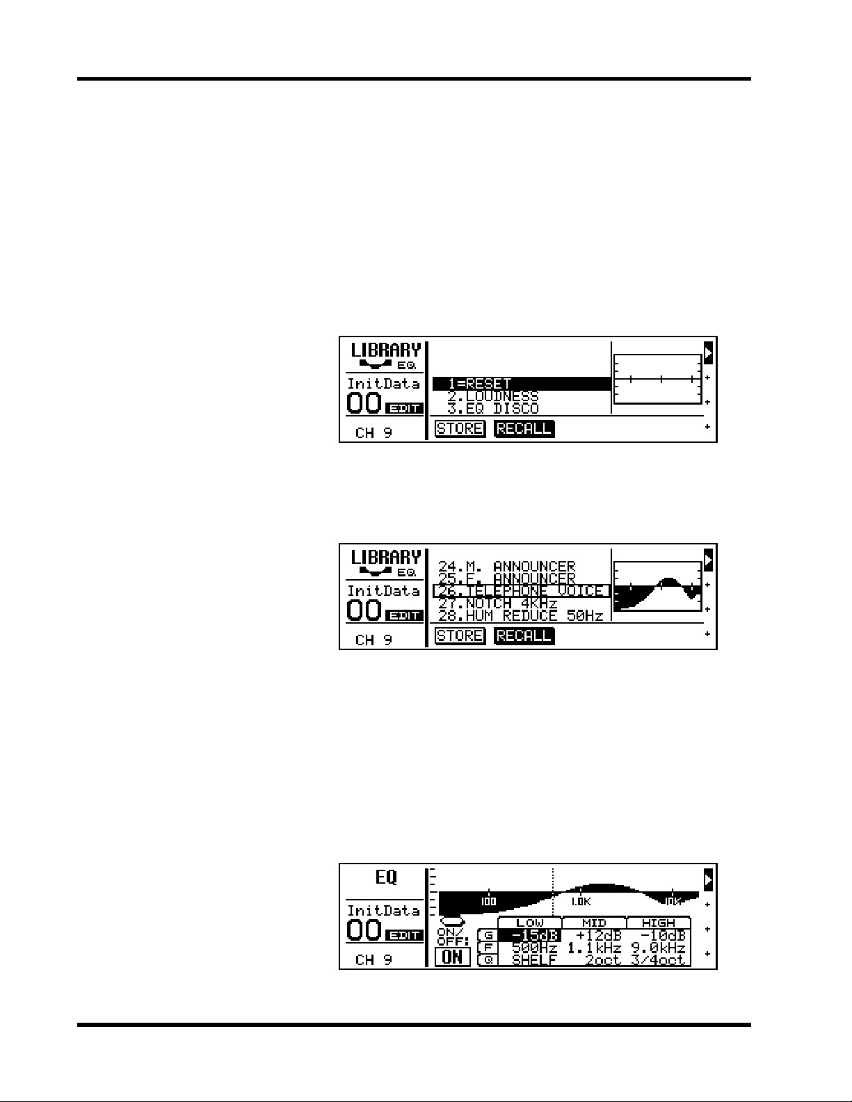
Well, that’s ProMix 01 EQ; flexible and intuitive. The following display shows some ex cessive EQ settings. Although they don ’t sound too
good, they do show off the EQ curve.
ProMix 01 Getting Started Guide
Page 24
18 Chapter 3: Basic Mixing Tutorial
ꎹ
Using the EQ Library
The EQ library is used to store EQ settings. It has 30 preset EQ programs and 20 user EQ programs for you to store your own custom
EQ settings. First we’ll look at recalling EQ programs, then how to
store your own.
Recalling an EQ Program
1. Press [LIBRARY].
The LIBRARY LCD function shown below appears.
2. Using the PARAMETER wheel, select program #26 (TELEPHONE VOICE).
The EQ curve of program #26 appears to the right of the program list
and the name and number flash.
ProMix 01 Getting Started Guide
3. Press [ENTER] to recall the program.
The program is recalled and channel 9’s EQ is set accordingly. Your
sound source now sounds like it ’s coming via long distance telephone.
The name and number of the EQ program stops flashing, appears
highlighted, and the period between its name and number changes
to an equal symbol (=), indicating that program #26 was the last program recalled. If the sound doesn’ t change, c heck whether you ’ve left
the EQ turned OFF on the EQ LCD function.
4. Press [EQ LOW] to go to the EQ LCD function. Here you can
see the parameter values and the EQ curve in more detail.
Page 25

Storing an EQ Program
Using the EQ Library 19
ꎹ
Now we ’ll edit the EQ and store it in the library as a user EQ program.
1. Set the EQ parameters how you like.
2. Press [LIBRARY] to return to the LIBRARY LCD function.
3. Press the [√] cursor button to select STORE.
EQ program #31, the first user program, is selected automatically.
4. Press [ENTER].
The LIBRARY NAME display shown below appears.
Here you can name y our custom EQ program for easy identification.
Program names can be up to 15 characters long.
5. Use the PARAMETER wheel to select characters and the [√]
and [®] cursor buttons to position the cursor in the name.
Spaces are available between upper and low er case letters, numerals,
and punctuation. Use them as spaces or to delete characters.
In this example we’ve named our program “My EQ Program”.
6. Press [ENTER] to store the program.
The message << Stored >> appears briefly, then the LIBRARY LCD
function reappears showing your new program.
You’ve now stored your own custom EQ program. If you’re happy
with the sound, go to the next section. If not, you can reset the EQ b y
recalling preset EQ program #1 (RESET). While STORE is selected
you cannot select and, therefor e, recall pr eset EQ programs. Press the
[
®] cursor button to select RECALL, then use the PARAMETER
wheel to select the preset EQ programs.
ProMix 01 Getting Started Guide
Page 26
20 Chapter 3: Basic Mixing Tutorial
ꎹ
CUE LCD Function
So far we’ve been monitoring channel 9 using the MIX CUE mode.
In this mode, the channel selected using the [SEL] buttons is monitored. When the CUE LCD function is selected, however, operation
is a little different, as we shall see.
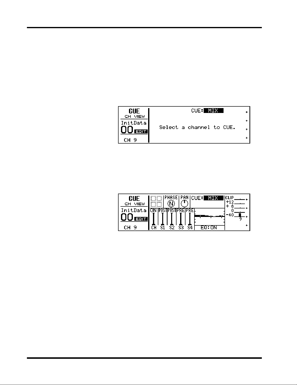
1. Press [CUE].
The sound is cut, all [SEL] button LEDs go OFF, and the CUE LCD
function shown below appears.
The message “ Select a channel to CUE” tells us that ProMix 01 is waiting for us to select the channels that we want to monitor.
2. Press channel 9’s [SEL] button.
The sound reappears, channel 9’s [SEL] button LED comes ON, and
various information about channel 9 is displayed. The signal level is
displayed by the meter to the right.
ProMix 01 Getting Started Guide
MIX CUE mode allows you to monitor a pre-fader CUE mix of
selected channels. The [SEL] buttons are used to add and remove
channels. The [SEL] button LEDs indicate which channels are
selected for the CUE mix. Information about the channel last added
or removed is displayed on the CUE LCD function.
Since we’re using only channel 9 for the moment, pressing other
channels’ [SEL] buttons won’t do much more than cause their [SEL]
button LEDs to light up. You ma y want t o c onnect a different sound
source to another input channel to try out MIX CUE mode.
As well as MIX, there ar e two more CUE modes: LAST CUE and ST
FIX. We’ll use ST FIX in the next section. See the User’s Guide for full
details on all CUE modes.
There is another CUE mode called LAST CUE. CUE is also affected
by the GROUP LCD function. See the User’s Guide for more details.
Page 27

Setting the CUE Mode 21
Setting the CUE Mode
ꎹ
ꎹ
For the rest of this tutorial and the next, we’ll use the ST FIX CUE
mode. In this mode, the MONITOR OUT and PHONES signals are
the same as those of the main STEREO OUTPUT.
1. Use the PARAMETER wheel to select ST FIX.
ST FIX flashes.
2. Press [ENTER] to confirm the setting.
The sound is cut and ST FIX appears highlighted. An y channels that
were in the previous CUE MIX are released. The following display
shows the CUE LCD function with the CUE mode set to ST FIX.
Channel 9 is selected.
Setting Fader Levels
To hear our sound source again we need to feed the channel 9 signal
to the main stereo outputs (i.e. the main stereo mix).
1. Set channel 9’s fader to the 0dB mark.
The 0dB fader position is a good place to start when setting fader levels. It’s a good setting with regard to signal level and noise performance and it leaves room for you to raise the level later, if necessary.
2. Set the ST OUT fader to the 0dB mark.
You can now hear your sound source and the stereo output meters
are indicating the stereo output level. The stereo mix signal is now
being output to the STEREO OUTs and digital and analog REC
OUTs.
Note that the Peak Hold function, which is set on the METER LCD
function, also works on the stereo output meters.
ProMix 01 Getting Started Guide
 Loading...