

PLASMA MONITOR
PDM-4220
SERVICE M A N UA L
SERVICE MANUAL
PDM-4220
Be sure to read this manual before servicing. To assure safety from fire, electric shock, injury, harmful radiation
and materials, various measures are provided in this Plasma display.
Be sure to read cautionary items described in the manual to maintain safety before servicing.
Service Warning
1. Since Panel Module and front Filter are made of glass, handling the broken Module and Filter shall be
taken care sufficiently in order not to be injured.
2. Replacing work shall be started after the Panel Module and the AC/DC Power supply become sufficiently
cool.
3. Special care shall be taken to the display area in order not to damage its surface.
4. The Panel Module shall not be touched with bare hand to protect its surface from stains.
5. It is recommended to use clean soft gloves during the replacing work in order to protect not only the display area of the Panel Module but also a serviceman himself.
6. The Chip Tube of Panel Module (located upper left of the back and surrounded by frame) and flexible
cables connecting Panel glasses to drive circuit PWBs are very weak, so shall be taken care sufficiently
not to break. If you break Chip Tube, the Panel doesn’t display anything forever.
■ CONTENTS
■ Features . . . . . . . . . . . . . . . . . . . . . . . . . . . . . . . . . .2
■ Specifications . . . . . . . . . . . . . . . . . . . . . . . . . . . . .3
■ Service points . . . . . . . . . . . . . . . . . . . . . . . . . . . . .4
■ Component names . . . . . . . . . . . . . . . . . . . . . . . . .5
■ Adjustment . . . . . . . . . . . . . . . . . . . . . . . . . . . . . . .6
■ Troubleshooting . . . . . . . . . . . . . . . . . . . . . . . . . .22
■ Self diagnosis function . . . . . . . . . . . . . . . . . . . . 32
Caution
■ Block diagram . . . . . . . . . . . . . . . . . . . . . . . . . . . .35
■ Connection diagram . . . . . . . . . . . . . . . . . . . . . . .36
■ Wiring diagram . . . . . . . . . . . . . . . . . . . . . . . . . . .37
■ Disassembly diagram . . . . . . . . . . . . . . . . . . . . . . 39
■ Replacement parts list . . . . . . . . . . . . . . . . . . . . .41
■ Diagnosis of the panel module . . . . . . . . . . . . .42
100985
© 2005 YAMAHA CORPORATION. All rights reseved.
This manual is copyrighted by YAMAHA and may not be copied or
redistributed either in print or electronically without permission.
’05.10

PDM-4220
PRECAUTIONS
How to clean the plasma screen panel of the monitor
Before cleaning the monitor, turn off the monitor and disconnect the power plug from the power outlet.
To prevent scratching or damaging the plasma screen face, do not knock or rub the surface with sharp or hard
objects. Clean the screen with a soft cloth moistened with warm water and dry with a soft cloth. If it is not
enough, then use a cloth with mild detergent. Do not use harsh or abrasive cleaners.
How to clean the cabinet of the monitor
Use a soft cloth to clean the cabinet and control panel of the monitor. When excessively soiled dilute a neutral
detergent in water, wet and wring out the soft cloth and afterward wipe with a dry soft cloth.
Never use acid/alkaline detergent, alcoholic detergent, abrasive cleaner, powder soap, OA cleaner, car wax,
glass cleaner, etc. especially because they would cause discoloration, scratches or cracks.
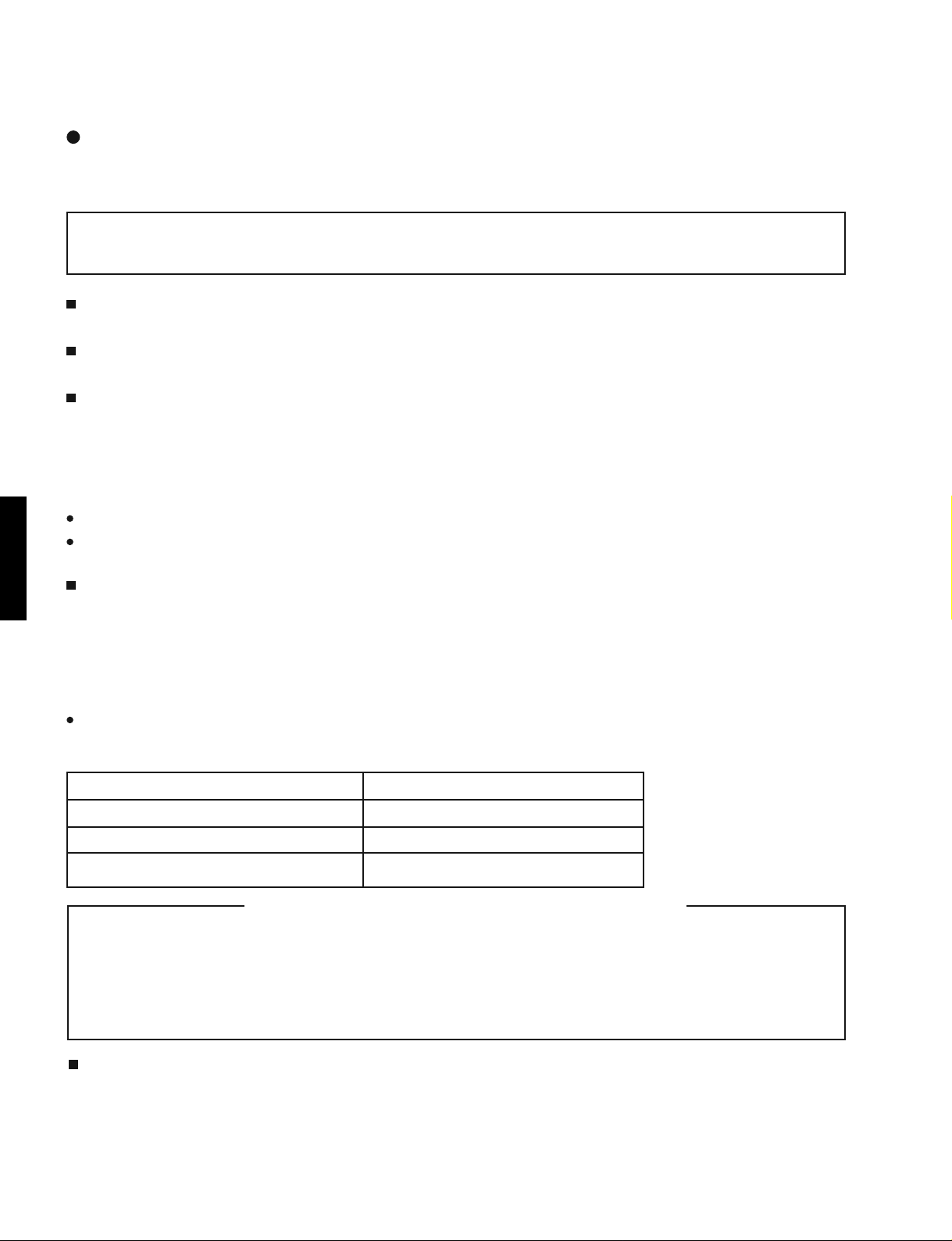
■
Features
Large-screen, high-definition plasma display panel
The 42-inch color plasma display panel, with a resolution of 1024 (H) x 1024 (V) pixels, creates a high-definition,
large-screen(aspect ratio : 16:9) and low-profile flat display. Free from electromagnetic interferences from geomagnetic sources and ambient power lines, the panel produces high-quality display images free from color misconvergence and display distortion.
High Performance Digital Processor
A wide range of input signals can be handed,including composite, component,and HDMI.High Definition Digital Processor creates the fine-textured image with dynamic contrast. In addition, it corresponds to a broad array of personal computer signals, from 640 x 400 and 640 x 480 VGA to 1600 x 1200 UXGA.(Analog Input)
Easy-to-use remote control and on screen display system
The remote control included eases the work of setting display controls. Further, the on-screen display system,
displays the status of signal reception and display control settings in an easy-to-view fashion.
PDM-4220
Power saving system
When connected to a VESA DPMS-compliant PC, the monitor cuts its power consumption while it is idle.
Connecting to an Audio Visual Device
1
· Three SCART terminals, a composite/S Terminal*
added. A composite video output terminal is also provided as a monitoring output.
*1
A composite/S terminal = A side input
· A wide range of devices other than personal computers can also be connected.
· A RGB input is possible to switch to component signal from the Menu screen.
Power Swivel Feature
It allows to turn the plasma display left or right within ± 30 degree using the remote control.
, a component terminal*2, a HDMI terminal and have been
2
■
Specifications
PDM-4220
Display
Panel
Net dimensions
(excluding Speakers/Stand)
Net weight
(excluding Speakers/Stand)
Ambient
conditions
Power supply
Power consumption/at standby
Audio output
(RGB input)
Input terminals
Input signals
Sync signals
(Video input)
Input terminals
Input signals
Output Signal
(RF input)
Input terminals
dimensions
Resolution
Temperature
Relative humidity
Approx. 42 inches (922 (H) x 522 (V) mm,
1024(H) x 1024 (V) pixels
1030 (W) x 636 (H) x 104 (D) mm
36.0kg
Operating : 5 °C to 35 °C, Storage : 0 °C to 40 °C
Operating : 20% to 80%, Storage : 20% to 90% (non-condensing)
AC100 - 240V, 50/60Hz
380W / <3W
speaker 12W + 12W (6Ω)
RGB1 DVI input terminal (DVI-D)
RGB1 audio input terminal (3.5mm Stereo Mini Jack)
RGB2 analog RGB input terminal (D-sub 15-pin)
RGB2 audio input terminal (3.5mm Stereo Mini Jack)
0.7 V/1.0 Vp-p, analog RGB (Recommended Signal)
480i, 576i, 480p, 576p, 1080i/50, 1080i/60, 720p/50*
H/V separate, TTL level [2KΩ ]
H/V composite, TTL level [2KΩ ]
Sync on green, 0.3 Vp-p [75Ω
AV1: composite video/S video/L/R audio input terminal (SCART)
AV2: composite video/RGB/L/R audio input terminal (SCART)
AV3: composite video/RGB/L/R audio input terminal (SCART)
AV4: composite video/Y/P
AV5: composite video/S video/L/R audio input terminal (RCA)
AV6: HDMI input terminal
AV1: PAL, SECAM, NTSC3.58, NTSC4.43
AV2: PAL, SECAM, NTSC3.58, NTSC4.43, RGB
AV3: PAL, SECAM, NTSC3.58, NTSC4.43, RGB
AV4: PAL, SECAM, NTSC3.58, NTSC4.43
AV4: 480i, 576i, 480p, 576p, 720p/50, 720p/60, 1080i/50, 1080i/60,
AV5: PAL, SECAM, NTSC3.58, NTSC4.43
AV6: HDMI input signal
OUTPUT (MONITOR): composite video monitor-output terminal (RCA)
OUTPUT (MONITOR): L/R audio monitor- output terminal (RCA)
OUTPUT (HEADPHONE): L/R audio monitor- output terminal (
ANT : 75Ω Unbalanced
]
B/PR
video/L/R audio input terminal (RCA)
diagonal 1059mm)
1
, 720p/60
3.5mm Stereo Mini Jack
PDM-4220
)
RF Video System
1
*
720/50 is supported by RGB1(DVI-STB)
2
The SECAM D,K system might not be normally received, depending on the model.
*
PAL B, G, H / I / D, K
SECAM B, G / K1 / L, Lí / (D, K)*
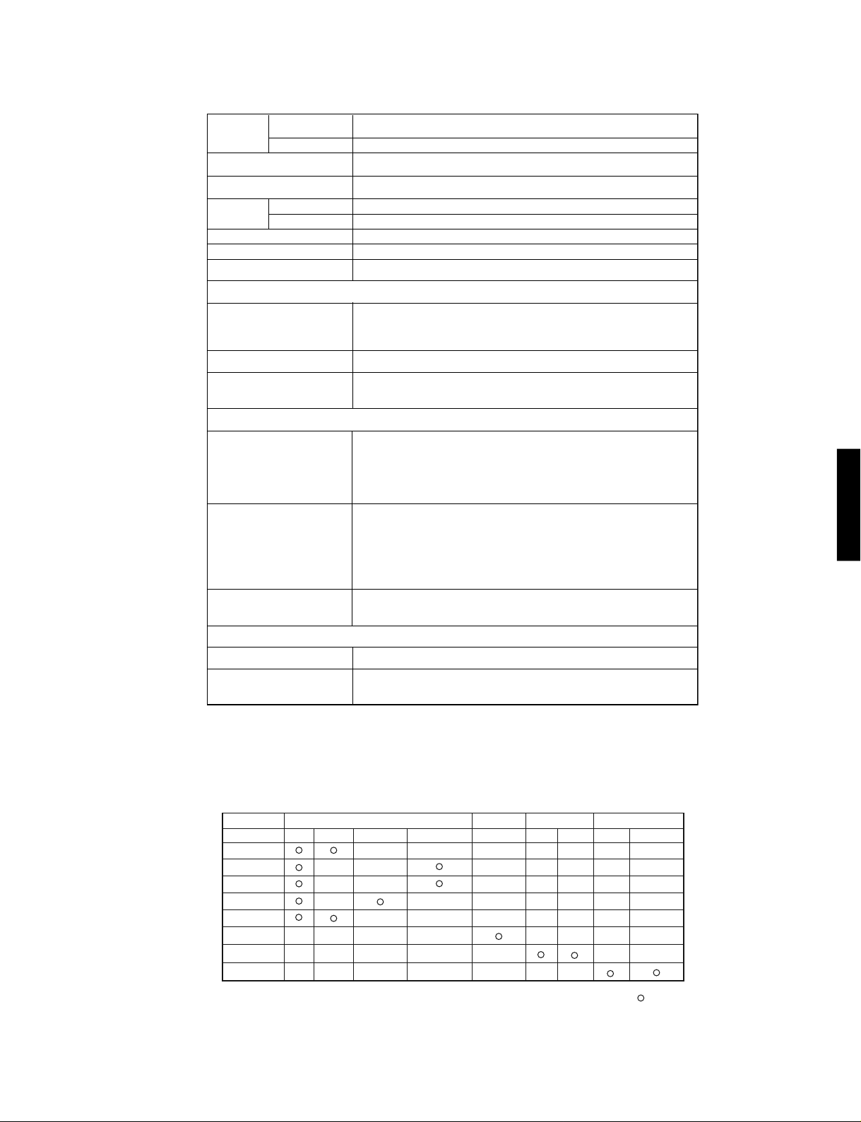
Applicable video signals for each input terminal
Terminal RCA/S-video/SCART DVI D-sub
Signal CVBS S-video Component SCART (RGB) PC STB RGB Component
AV1
AV2
AV3
AV4
AV5
AV6
RGB1
RGB2
2
HDMI
( :Available)
3
PDM-4220
■
Service points
Lead free solder
This product uses lead free solder (unleaded) to help preserve the environment. Please read these instructions
before attempting any soldering work.
Caution: Always wear safety glasses to prevent fumes or molten solder from getting into the eyes. Lead free
solder can splatter at high temperatures (600 °C).
Lead free solder indicator
Printed circuit boards using lead free solder are engraved with an "F."
Properties of lead free solder
The melting point of lead free solder is 40-50 °C higher than leaded solder.
Servicing solder
Solder with an alloy composition of Sn-3.0Ag-0.5Cu or Sn-0.7Cu is recommended.
Although servicing with leaded solder is possible, there are a few precautions that have to be taken. (Not taking
these precautions may cause the solder to not harden properly, and lead to consequent malfunctions.)
Precautions when using leaded solder
Remove all lead free solder from soldered joints when replacing components.
If leaded solder should be added to existing lead free joints, mix in the leaded solder thoroughly after the lead
free solder has been completely melted (do not apply the soldering iron without solder).
Servicing soldering iron
PDM-4220
A soldering iron with a temperature setting capability (temperature control function) is recommended.
The melting point of lead free solder is higher than leaded solder. Use a soldering iron that maintains a high
stable temperature (large heat capacity), and that allows temperature adjustment according to the part being
serviced, to avoid poor servicing performance.
Recommended soldering iron:
Soldering iron with temperature control function (temperature range: 320-450 °C)
Recommended temperature range per part:
Part Soldering iron temperature
Mounting (chips) on mounted PCB 320 °C±30 °C
Mounting (chips) on empty PCB 380 °C±30 °C
Chassis, metallic shield, etc. 420 °C±30 °C
The PWB assembly which has used lead free solder
FILTER PWB, SW PWB, LED/RECEIVER PWB, SP TERMINAL(L/R) PWB
AUDIO PWB, JOINT PWB, Swievel PWB, HDMI PWB, control PWB
VIDEO PWB
TUNER PWB
Readjustment Power supply voltage
When a PANEL or a Power Unit is exchanged, power supply voltage needs to be adjusted. Please adjust to
make the values of Va and Vs of as should on the label currently stuck on the panel back upper parts.Adjustment is performed by VR in the power supply unit. Please refer to the procedures of "Va" and "Vs" adjustments
on 17page.
4
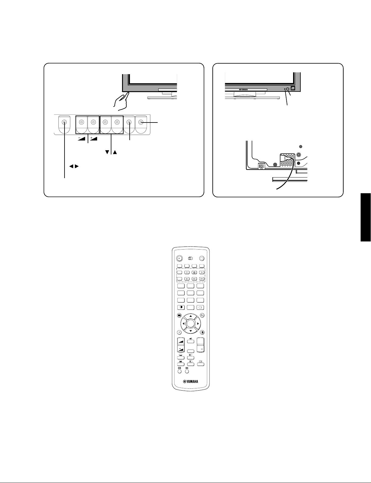
• ( ) indicates the function while the MENU is displayed on the screen.
Remote-control
receiver
Indicating lamp
Menu button
INPUT SELECT button
(OK button)
CHANNEL
UP/DOWN buttons
(SELECT button)
SUB-POWER button
VOLUME
UP/DOWN
buttons
(
ADJUST
buttons)
• Adjustment buttons are located
on the bottom.
• The back cover is provided with
indications to distinguish the
adjustment buttons.
•The main power switch is located at the
back, on the lower surface.
Main power switch
■
Component names
[Main unit]
PDM-4220
[Remote control]
STANDBY/ON
/I
AV 1 AV 2 AV 3 AV 4
AV 5
1
456
7809
2-4-12
MENU
A. MODE P. MODE
VOL PROG
+
RECALL
DVD
TV
AV 6 RGB 1 RGB 2
23
RETURN
OK
P
I/II
?
i
+
i
+
P
PDM-4220
5

PDM-4220
■
Adjustment
• How to get to Adjustment mode
Using the front control buttons with the set turned off (standby) can activate it.
Press the SUB-POWER(
more than 5 seconds.
The set turns on in adjustment mode with OSD.
• Changing data and Selecting Adjustment code
When the set is in adjustment mode, the cursor , , , and OK buttons of the remote control or front panel
may be used as the adjustment keys.
, buttons are used for selecting adjustment code.
, buttons are used for changing data values.
OK button is used for confirming the data.
After finishing the necessary adjustment press MENU button. Adjustment mode is released and the set returns to
normal condition.
) button, INPUT SELECT( ) button and button at the same time, and hold for
• Memory Initialize operation
NOTE: The execution of this function returns the adjustment codes to the preset values, therefore, adjustment
data will be lost.
Procedure
(1) Enter Adjustment Mode.
(2) Select MEMORY INIT adjustment code (No.658) and change the data value from 0 to 1.
PDM-4220
(3) Activate MEMORY INIT by pressing OK button for more than 3 seconds.
(4) Select No.525 and change data value from 1 to 0.
(5) Check that the receiving channel goes to P1. Unit is set to preset values.
6

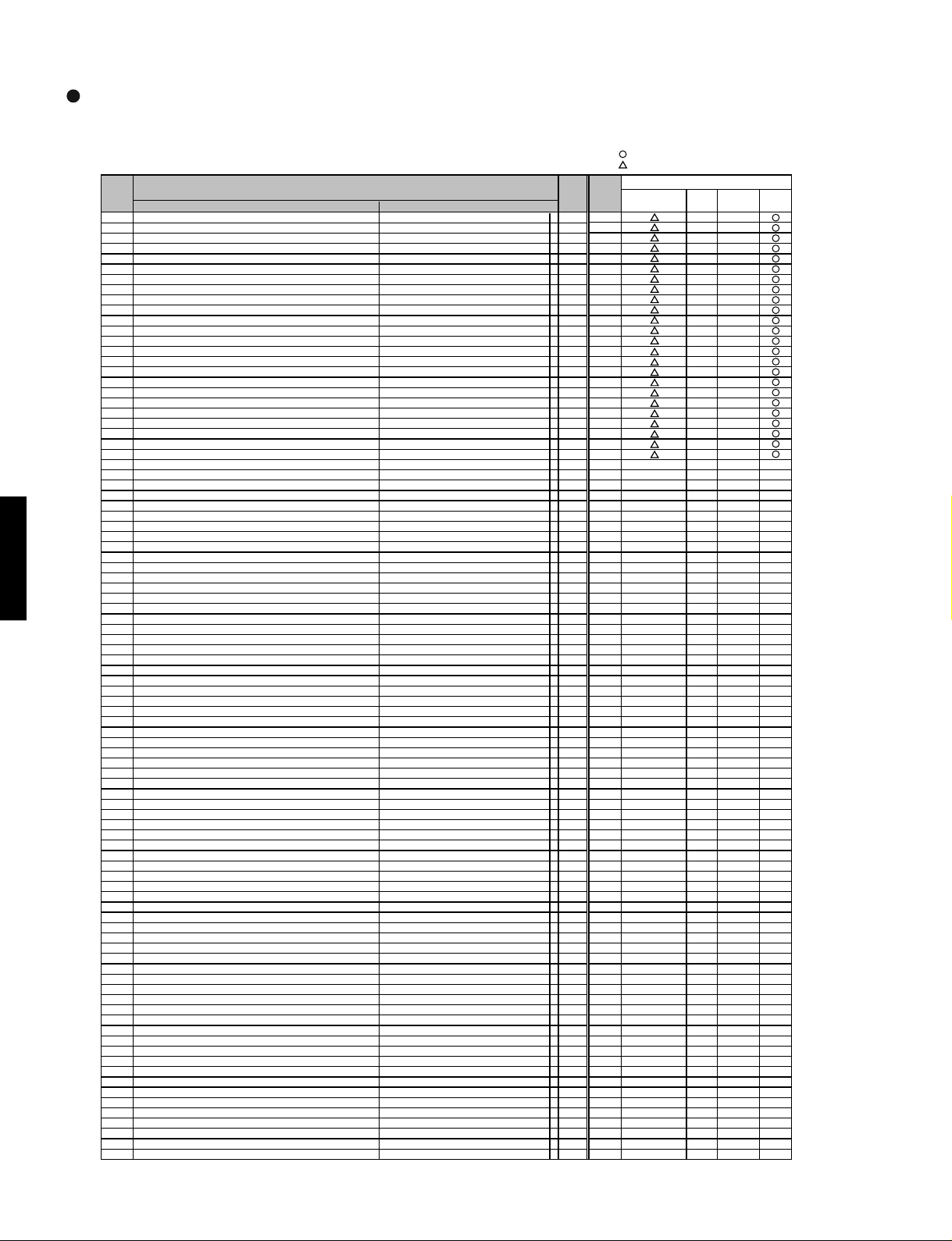
PDM-4220
Service adjustment items by I
ADJ Function Max. Default
No
0 SUB_CONTRAST (RF) Main 15 8
1 SUB_CONTRAST (AV1) Main/Sub Composite mode 15 8
2 SUB_CONTRAST (AV2) Main/Sub Composite mode 15 8
3 SUB_CONTRAST (AV3) Main/Sub Composite mode 15 8
4 SUB_CONTRAST (AV4) Main/Sub Composite mode 15 8
5 SUB_CONTRAST (AV5) Main/Sub Composite mode 15 8
6 SUB_CONTRAST (RF) Sub 15 8
7 Sub Color Main 15 8
8 Sub Color Sub 15 8
9 TINT (RF
10 TINT (VIDEO) Main 63 33
11 TINT (RF) Sub 63 33
12 TINT (VIDEO) Sub 63 33
13 Free
14 Free
15 Free
16 Free
17 Reference Amplitude(RGB_AMP) RF/VIDEO 254 127
18 Reference Amplitude(RGB_AMP) PC 254 127
19 Reference Amplitude(RGB_AMP) Multi Picture mode 254 130
20 Display for Max. Amplitude Level Main - 21 Display for Max. Amplitude Level Sub - 22 Offset Value(+/-) of Upper Limit (for FC :RGB-AMP ) Multi Picture mode 18 2
23 Offset Value(+/-) of Upper Limit (for TB1274:SUB-CONT) Single Picture mode 18 2
24 Offset Value(+/-) of Upper Limit (for TB1274:Sub Color) 18 2
25 Terget value of White peak Adj. Single Picture mode 237 235
26 Terget value of Color Level Adj. (for TB1274:Sub Color) 237 235
27 Set Blue Gamma
28 Contrast mode<Dynamic> SW (TV) 0:Dynamic, 1:Dynamic+Auto RF 1 1
29 Select for WIDE Mode 11
30 PinP Function (for PC) 0:PinP, 1:Infomation1, 2:Infomaiton Split 2 0
31 Black Level(RGB_AMP) RF/VIDEO 254 127
32 Black Level(RGB_AMP) PC 254 127
33 Black Level(RGB_AMP) HDMI 254 127
34 Black Level(RGB_AMP) For USA NTSC/480i 254 127
35 YNR Input Level for AV1-5 Mode RF 7 7
36 YNR Input Level for AV1-5 Mode VIDEO 7 7
37 YNR Input Level for AV1-5 Mode Scart-RGB(50/60Hz) 7 7
38 YNR Input Level for AV1-5 Mode 480i/576i 7 7
39 YNR Input Level for AV1-5 Mode 480p/576p 7 7
40 YNR Input Level for AV1-5 Mode 1080i-50/60/720p 7 7
41 YNR In
42 YNR Input Level for DVI-STV Mode 1080i-50/60/720p 7 7
43 CNR Input Level at Low level for AV1-5 Mode RF/VIDEO 7 4
44 CNR Input Level at Low level for AV1-5 Mode Scart-RGB(50/60Hz) 7 4
45 CNR Input Level at Low level for AV1-5 Mode 480i/576i 7 4
46 CNR In
47 CNR Input Level at Low level for AV1-5 Mode 1080i-50/60/720p 7 4
48 CNR Input Level at Low level for DVI-STV Mode 480i/480p/576i/576p/VGA 7 2
49 CNR Input Level at Low level for DVI-STV Mode 1080i-50/60/720p 7 2
50 CNR Input Level at Low level for Dsub Comp. Mode 480i/576i 7 2
51 CNR Input Level at Low level for Dsub Comp. Mode 480p/576p 7 2
52 CNR Input Level at Low level for Dsub Comp. Mode 1080i-50/60/720p 7 2
53 main/sub YFRNR level [MYNRP0] NTSC/PAL/ Multipicture 7 1
54 main/sub YFRNR level [MYNRP5] NTSC/PAL-VIDEO 7 0
55 main/sub YFRNR level [MYNRP6'] Scart-RGB(50/60Hz) 7 0
56 main/sub YFRNR level [MYNRP6] 70
57 main/sub YFRNR level
58 main/sub YFRNR level [MYNRP8] 70
59 main/sub CFRNR level [MCNRP0] NTSC/PAL/ 7 0
60 main/sub CFRNR level [MCNRP5] NTSC/PAL-VIDEO 7 0
61 main/sub CFRNR level [MCNRP6'] Scart-RGB(50/60Hz) 7 0
62 main/sub CFRNR level [MCNRP6] 480i/576i 7 0
63 main/sub CFRNR level [MCNRP7] 480p/576p 7 0
64 main/sub CFRNR level [MCNRP8] 1080i-50/60/720p 7 0
65 B-Y/B R-Y/R(VER. Enhancer Gain) [CVEG0] NTSC/PAL/480i/576i/ Multi picture 15 15
66 B-Y/B R-Y/R (VER. Enhancer Gain) [CVEG1] 480p/576p/1080i-50/60/720p 15 9
67 DSB Gain of Vertical for B-Y/B R-Y/R [CVDSBG0] NTSC/PAL/480i/576i/ Multi picture 3 0
68 DSB Gain of Vertical for B-Y/B R-Y/R [CVDSBG1] 480p/576p/1080i-50/60/720p 3 0
69 DSB corin
70 DSB coring of Vertical for B-Y/B R-Y/R [CVDSBC1] 480p/576p/1080i-50/60/720p 7 0
71 B-Y/B R-Y/R (VRE. Enhancer) CLIP 0:CTI [CVECLP0] NTSC/PAL/480i/576i/ Multi picture 1 0
72 B-Y/B R-Y/R (VRE. Enhancer) CLIP 0:CTI [CVECLP1] 480p/576p/1080i-50/60/720p 1 0
73 Horizontal HPF Peek Fre
74 Horizontal HPF Peek Freq. SW for B-Y/B,R-Y/R [CHHPF1] 480p/576p/1080i-50/60/720p 3 2
75 Horizontal Enhancer Gain for B-Y/B,R-Y/R [CHEG0] NTSC/PAL/480i/576i/ Multi picture 15 15
76 Horizontal Enhancer Gain for B-Y/B,R-Y/R [CHEG1] 480p/576p/1080i-50/60/720p 15 9
77 Horizontal DSB Gain for B-Y/B,R-Y/R [CHDSBG0] NTSC/PAL/480i/576i/ Multi picture 3 0
78 Horizontal DSB Gain for B-Y/B,R-Y/R [CHDSBG1] 480p/576p/1080i-50/60/720p 3 0
79 Horizontal DSB Coring for B-Y/B,R-Y/R [CHDSBC0] NTSC/PAL/480i/576i/ Multi picture 7 0
80 Horizontal DSB Corin
81 Horizontal Enhancer Clip for B-Y/B,R-Y/G 0:CTI [CHECLP0] NTSC/PAL/480i/576i/ Multi picture 1 0
82 Horizontal Enhancer Cli
83 B-Y Clam
84 R-Y Clamp offset NTSC/PAL/480i/576i/480p/576p 255 128
85 B-Y Clamp offset 1080i-50/60 255 128
86 R-Y Clamp offset 1080i-50/60 255 128
87 B-Y Clamp offset 720p 255 128
88 R-Y Clamp offset 720p 255 128
89 B-Y Clamp offset [DVI-STB] 480i/576i/480p/576p/VGA 255 128
90 R-Y Clamp offset [DVI-STB] 480i/576i/480p/576p/VGA 255 128
91 B-Y Clam
92 R-Y Clamp offset [DVI-STB] 1080i-50/60 255 128
93 B-Y Clamp offset [DVI-STB] 720p 255 128
94 R-Y Clam
95 P/N ID Main 1 0
96 P/N ID Sub 1 0
97 Shar
98 Free
99 Free
) Main 63 33
gain On/Off 0:Off, 1:On (For 55V) For 55V 1 1
put Level for DVI-STV Mode 480i/480p/576i/576p/VGA 7 7
put Level at Low level for AV1-5 Mode 480p/576p 7 4
g of Vertical for B-Y/B R-Y/R [CVDSBC0] NTSC/PAL/480i/576i/ Multi picture 7 0
g for B-Y/B,R-Y/R [CHDSBC1] 480p/576p/1080i-50/60/720p 7 0
p offset NTSC/PAL/480i/576i/480p/576p 255 128
p offset [DVI-STB] 1080i-50/60 255 128
p offset [DVI-STB] 720p 255 128
pness Gain(RF/NR)
ADJ. Items Mode PWB PWB PWB PANEL
[MYNRP7] 70
q. SW for B-Y/B,R-Y/R [CHHPF0] NTSC/PAL/480i/576i/
p for B-Y/B,R-Y/G 0:CTI [CHECLP1] 480p/576p/1080i-50/60/720p 1 0
2
C-bus control (MAIN Part)
value
480i/576i(Except HDMI)
480p/576p(Except HDMI)
1080i-50/60/720p(Except HDMI)
Multi
Multi
picture 3 2
Main/Sub 15 2
: shoule be adjusted
: should be followed previous data
FORMATTER VIDEO TUNER PDP
Changed Component
PDM-4220
7

PDM-4220
p
p
p
p
p
p
p
p
p
p
p
)
p
p
p
p
p
p
p
p
p
p
(
)
(
)
(
)
(
)
(
)
(
)
(
)
(
)
(
)
(
)
(
)
(
)
(
)
(
)
(
)
(
)
(
)
(
)
(
)
(
)
(
)
(
)
(
)
(
)
(
)
(
)
(
)
(
)
(
)
(
)
(
)
(
)
(
)
(
)
(
)
p
(RF)
(
)
(
)
(
)
(
)
(
)
(
)
(
)
(L)
(L')
(
)
(
)
(
)
(
)
(
)
(
)
(
)
(
)
(
)
(
)
(L)
(L')
(
)
(
)
(
)
(
)
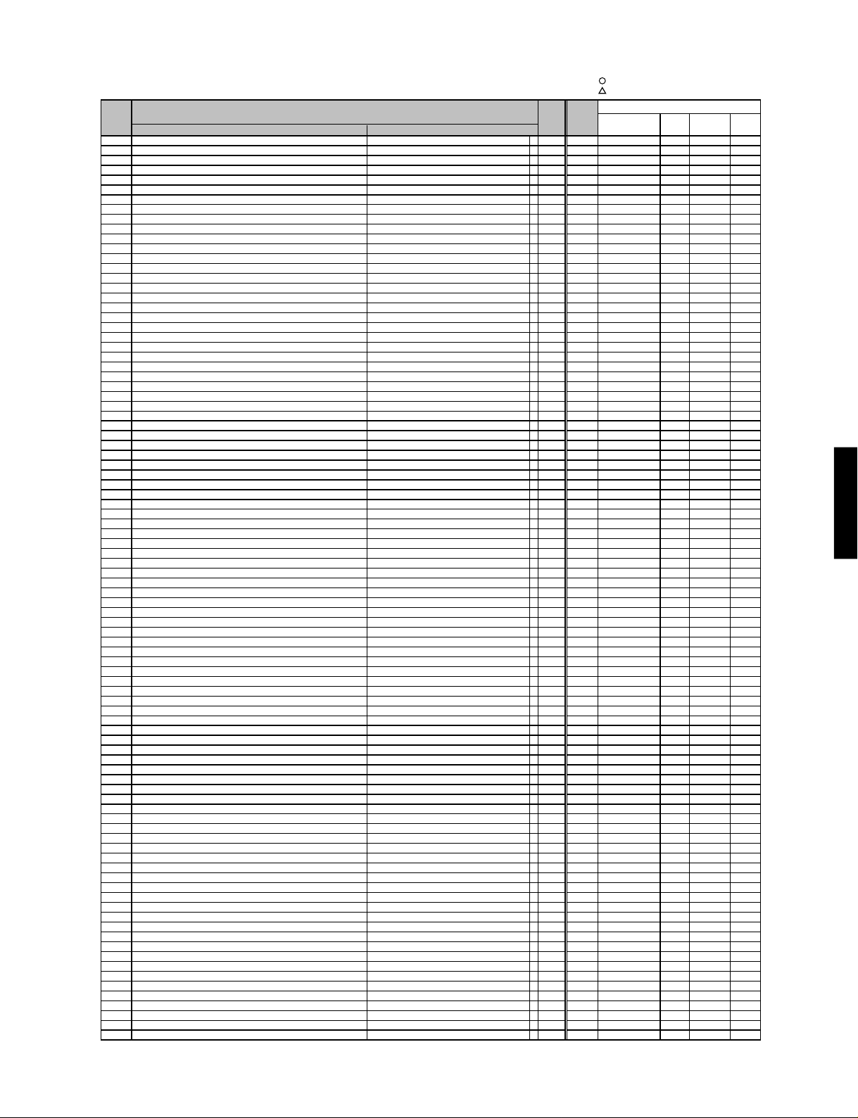
ADJ Function Max. Default
No
100 Free
101 Free
102 Free
103 Free
104 Free
105 Free
106 Free
107 Free
108 Free
109 Free
110 Shar
111 Shar
112 Shar
113 Shar
114 Shar
115 Shar
116 Shar
117 Shar
118 Shar
119 Shar
120 Shar
121 Free
122 Shar
123 Shar
124 Shar
125 Shar
126 Shar
127 Shar
128 Shar
129 Shar
130 Shar
131 Shar
132 Free
133 Y Out Level M
134 Y Out Level B/G
135 Y Out Level D/K
136 Y Out Level I
137 Y Out Level L
138 Y Out Level L'
139 Y Out Level
140 Y Out Level
141 Free
142 Y Out Level M
143 Y Out Level B/G
144 Y Out Level D/K
PDM-4220
145 Y Out Level I
146 Y Out Level L
147 Y Out Level L'
148 Y Out Level
149 Y Out Level
150 Free
151 C Out Level M
152 C Out Level B/G
153 C Out Level D/K
154 C Out Level I
155 C Out Level L
156 C Out Level L'
157 C Out Level
158 C Out Level
159 Free
160 C Out Level M
161 C Out Level B/G
162 C Out Level D/K
163 C Out Level I
164 C Out Level L
165 C Out Level L'
166 C Out Level
167 C Out Level
168 Free
_Q
169 BPF
170 BPF_f0
171 C_TRAP_SW
172 LPF Main/Sub 1 0
173 SECAM D-Tra
174 FILTER SW
175 Y_DL
176 Y_DL
_DL
177 Y
178 Y_DL
179 Y_DL
180 Y
_DL
181 Y_DL
182 Y_DL
183 Y_DL
184 Y_DL
185 Y_DL
_DL
186 Y
187 Y_DL
188 Y_DL
189 Y_DL
190 Y_DL
191 Y_DL
192 Y_DL
193 Y_DL
_DL
194 Y
195 Y_DL
196 Y_DL
197 Y_DL
198 Y_DL
199 NTSC Comb
value
ADJ. Items Mode PWB PWB PWB PANEL
ness Gain(RF) BG/DK/I Sub 15 8
ness Gain(RF) M Sub 15 8
ness Gain(RF) L Sub 15 8
ness Gain(RF) L' Sub 15 8
ness Gain(VIDEO) PAL Sub 15 8
ness Gain(VIDEO) NTSC3.58 Sub 15 8
ness Gain(VIDEO) SECAM,B/W Sub 15 8
ness Gain(VIDEO) NTSC4.43 Sub 15 8
ness Gain(VIDEO) N-PAL Sub 15 8
ness Gain(VIDEO) M-PAL Sub 15 8
ness Gain(S.VIDEO
ness f0(RF) BG/DK/I Main/Sub 3 2
ness f0(RF) M Main/Sub 3 2
ness f0(RF) L Main/Sub 3 2
ness f0(RF) L' Main/Sub 3 2
ness f0(VIDEO) PAL Main/Sub 3 2
ness f0(VIDEO) NTSC3.58 Main/Sub 3 2
ness f0(VIDEO) SECAM,B/W Main/Sub 3 2
ness f0(VIDEO) NTSC4.43 Main/Sub 3 2
ness f0(VIDEO) N-PAL Main/Sub 3 2
ness f0(VIDEO) M-PAL Main/Sub 3 2
4.5
5.5
6.5
6.0
6.5
6.5
VIDEO
TEXT
4.5
5.5
6.5
6.0
6.5
6.5
VIDEO
TEXT
4.5
5.5
6.5
6.0
6.5
6.5
VIDEO
TEXT
4.5
5.5
6.5
6.0
6.5
6.5
VIDEO
TEXT
4.43MHz
4.43MHz
COMB=OFF-PAL/NTSC4.43/NTSC3.58
4.5MHz
5.5MHz PAL/NTSC4.43
5.5MHz SECAM
6.0PAL/NTSC4.43
6.0SECAM
6.5PAL/NTSC4.43
6.5SECAM
VIDEO PAL/NTSC4.43
VIDEO SECAM
VIDEO NTSC
4.5MHz
5.5MHz PAL/NTSC4.43
5.5MHz SECAM
6.0PAL/NTSC4.43
6.0SECAM
6.5PAL/NTSC4.43
6.5SECAM
VIDEO PAL/NTSC4.43
VIDEO SECAM
VIDEO NTSC
Comb off
Sub 15 10
Main 63 15
Main 63 13
Main 63 16
Main 63 14
Main 63 13
Main 63 16
Main 63 15
Main 63 0
Sub 63 19
Sub 63 13
Sub 63 12
Sub 63 13
Sub 63 12
Sub 63 15
Sub 63 13
Sub 63 4
Main 63 7
Main 63 7
Main 63 7
Main 63 7
Main 63 8
Main 63 8
Main 63 15
Main 63 6
Sub 63 3
Sub 63 8
Sub 63 8
Sub 63 7
Sub 63 7
Sub 63 7
Sub 63 10
Sub 63 8
Main/Sub 3 3
Main/Sub 3 1
Main/Sub 1 0
Main/Sub 1 1
Main/Sub 1 0
Main 10 6
Main 10 4
Main 10 0
Main 10 8
Main 10 9
Main 10 6
Main 10 10
Main 10 5
Main 10 5
Main 10 6
Main 10 8
Main 10 6
Sub 10 5
Sub 10 2
Sub 10 0
Sub 10 7
Sub 10 5
Sub 10 5
Sub 10 5
Sub 10 5
Sub 10 5
Sub 10 5
Sub 10 5
Sub 10 5
Sub 1 1
: shoule be adjusted
: should be followed previous data
FORMATTER VIDEO TUNER PDP
Changed Component
8
ADJ Function Max. Default
)
(
)
(
)
(
)
(
)
(
)
(
)
(
)
p
p
p
p
p
p
p
p
p
p
p
p
p
p
p
p
p
p
0
p
p
p
0
p
p
p
0
p
p
p
0
p
p
p
0
p
p
p
0
p
k
m
k
n
No
200 Cb offset1 Main
201 Free
202 Cr offset1 Main
203 Free
204 Cb offset1 Sub
205 Free
206 Cr offset1 Sub
207 Free
208 MVM (VIDEO
209 AFC_GAIN
210 AFC_GAIN
211 AFC_GAIN
212 AFC_GAIN
213 AFC_GAIN
214 AFC_GAIN
215 AFC_GAIN
216 S_B-Y_ADJ Main
217 S_R-Y_ADJ Main
218 S_B-Y_ADJ Sub
219 S_R-Y_ADJ Sub
220 BELL_f0 Main/Sub
221 S_INHBT
222 S_ID
223 S_GP
224 S_V_ID
225 BELL/HPF
226 HS Phase Main
227 HS Phase Sub
228 Bandwidth 1 NTSC/PAL/480i/576i
229 Bandwidth 1 480
230 Bandwidth 1 1080i-50/60/720
231 Bandwidth 2 NTSC/PAL/480i/576i
232 Bandwidth 2 480
233 Bandwidth 2 1080i-50/60/720
234 Sub Contrast 1 Exce
235 Sub Contrast 1 HDMI
236 Sub Contrast 2 Exce
237 Sub Contrast 2 HDMI
238 Sub Color 1 Exce
239 Sub Color 1 HDMI
240 Sub Color 2 Exce
241 Sub Color 2 HDMI
242 HV THRU 1 NTSC/PAL/480i/576i/480
243 HV THRU 1 1080i-50/60/720
244 HV THRU 2 NTSC/PAL/480i/576i/480
245 HV THRU 2 1080i-50/60/720
246 H_SEP 1 RF/VIDEO
247 H_SEP 1 480i/576i
248 H
249 H_SEP 1 1080i_5
250 H_SEP 1 1080i_60/720
251 H_SEP 2 RF/VIDEO
252 H_SEP 2 480i/576i
253 H
254 H_SEP 2 1080i_5
255 H_SEP 2 1080i_60/720
256 V_SEP 1 RF/VIDEO
257 V_SEP 1 480i/576i
258 V_SEP 1 480
259 V_SEP 1 1080i_5
260 V
261 V_SEP 2 RF/VIDEO
262 V_SEP 2 480i/576i
263 V_SEP 2 480
264 V_SEP 2 1080i_5
265 V_SEP 2 1080i_60/720
266 AFC MODE 1 RF
267 AFC MODE 1 VIDEO
268 AFC MODE 2 RF
AFC MODE 2 VIDEO
269
270 N_LVL 1 RF
271 N_LVL 1 VIDEO
272 N_LVL 2 RF
273 N_LVL 2 VIDEO
274 Free
275 HD POSITION 1 480i/576i
276 HD POSITION 1 480
277 HD POSITION 1 1080i
278 HD POSITION 1 1080i_60/720
279 Free
280 HD POSITION 2 480i/576i
281 HD POSITION 2 480
282 HD POSITION 2 1080i_5
283 HD POSITION 2 1080i_60/720
284 Y LPF 1 RF
285 Y LPF 1 VIDEO
286 Y LPF 2 RF
287 Y LPF 2 VIDEO
288 Gain 1
289 Gain 2
290 YCS MODE NTSC3.58
291 3D DET
AFC Gain NTSC3.58
292
293 2D-CNR
294 2D-CNR Li
295 GMCON
296 Y-NC
297 Y-NC Lim
298 2D-YNR
299 2D-YNR Gai
AV00
AV1
AV2
AV3
AV4
AV5
Except AV00
_SEP 1 480
_SEP 2 480
_SEP 1 1080i_60/720
ADJ. Items Mode PWB PWB PWB PANEL
/576
/576
t HDMI
t HDMI
t HDMI
t HDMI
/576
/576
/576
/576
/576
/576
/576
_5
/576
value
15 8
15 8
15 8
15 8
10
30
30
30
30
30
30
30
15 8
15 8
15 8
15 8
10
10
10
30
10
33
10
10
32
32
30
32
32
30
15 0
15 0
15 0
15 0
15 0
15 0
15 0
15 0
10
10
10
10
10
10
10
10
10
10
10
10
10
10
10
10
10
10
10
10
10
10
10
10
30
30
30
30
10
10
10
10
15 0
15 0
15 0
15 0
15 0
15 0
15 0
15 0
11
11
11
11
11
11
30
77
30
30
30
10
10
30
30
30
PDM-4220
: shoule be adjusted
: should be followed previous data
FORMATTER VIDEO TUNER PDP
Changed Component
PDM-4220
9
PDM-4220
ADJ Function Max. Default
No
300 2D-YNR Lim
301 BLK EXP
302 CKILL
put Clamp
303 Out
304 Input Clamp auto
305 Int Clamp Manual
306 C-ENHA
307 YC-MIX
308 Video2 RGB Mode ON
309 HSWINV
310 Free
311 V-ENHA Gain NTSC3.58
312 V-ENHA NL NTSC3.58
313 H-ENHA Gain NTSC3.58
314 3DNR Corr for 3DYCS
315 Burst ON for 2DYCS????
316 MDMPL
317 MDMBL
318 H-MaskOut
319 V-MaskOut
put Y-Delay (Main RF mode) for 3DYCS
320 In
321 Input Y-Delay (Main Video mode) for 3DYCS
322 Output-Y-Delay (Main RF Mode) for 3DYCS
323 Output-Y-Delay (Main Video Mode) for 3DYCS
324 V-ENHA Core NTSC3.58
325 Input Clamp Key NTSC3.58
326 Burst Gate Key NTSC3.58
327 Sync sep LPF NTSC3.58
328 H-WST NTSC3.58
329 HD Amp 1 NTSC3.58
330 HD Gain V NTSC3.58
331 HD Amp 2 NTSC3.58
332 HD Gain 1 NTSC3.58
333 HD Amp 3 NTSC3.58
334 HD Gain 2 NTSC3.58
335 ACMSLP NTSC3.58
ACSSLP NTSC3.58
336
337 AYMSLP NTSC3.58
338 AYSSLP NTSC3.58
339 ACMESET NTSC3.58
340 ACMFSET NTSC3.58
341 ACSESET NTSC3.58
342 ACSFSET NTSC3.58
343 AYMESET NTSC3.58
AYMFSET NTSC3.58
344
PDM-4220
345 AYSESET NTSC3.58
346 AYSFSET NTSC3.58
347 BCMSLP NTSC3.58
348 BCSSLP NTSC3.58
349 BYMSLP NTSC3.58
350 BYSSLP NTSC3.58
351 BCMESET NTSC3.58
352 BCMFSET NTSC3.58
353 BCSESET NTSC3.58
354 BCSFSET NTSC3.58
355 BYMESET NTSC3.58
356 BYMFSET NTSC3.58
357 BYSESET NTSC3.58
358 BYSFSET NTSC3.58
359 BCMUP NTSC3.58
360 CECMP NTSC3.58
361 CSCMP NTSC3.58
362 F1HE
363 F1VER NTSC3.58
364 MREF NTSC3.58
365 CDEYE NTSC3.58
366 YDEYE NTSC3.58
367 MDS NTSC3.58
368 F-TBC OFF MDMPL NTSC3.58
369 REC:C
370 V-ENHA Gain Except NTSC3.58
371 V-ENHA NL Except NTSC3.58
372 H-ENHA Gain Except NTSC3.58
373 3D-CNR Lim for 2DYCS
374 3D-CNR k for 2DYCS
375 3D-CNR Gain for 2DYCS
376 3D-YNR Lim for 2DYCS
377 3D-YNR k for 2DYCS
378 3D-YNR Gain for 2DYC
379 YCS MODE Except NTSC3.58
380
AFC Gain Except NTSC3.58
381 Free
382 Free
383 V-ENHA Core Except NTSC3.58
384 Input Clamp Key Except NTSC3.58
385 Burst Gate Key Except NTSC3.58
ync sep LPF Except NTSC3.58
386 S
387 H-WST Except NTSC3.58
388 HD Amp 1 Except NTSC3.58
389 HD Gain V Except NTSC3.58
390 HD Amp 2 Except NTSC3.58
391 HD Gain 1 Except NTSC3.58
392 HD Amp 3 Except NTSC3.58
393 HD Gain 2 Except NTSC3.58
ACMSLP Except NTSC3.58
394
395 ACSSLP Except NTSC3.58
396 AYMSLP Except NTSC3.58
397 AYSSLP Except NTSC3.58
398 ACMESET Except NTSC3.58
399
ACMFSET Excep
ADJ. Items Mode PWB PWB PWB PANEL
R NTSC3.58
_DEC Except NTSC3.58
S
t NTSC3.58
value
30
30
10
10
11
10
10
10
10
10
32
32
31
10
10
10
10
70
70
74
74
15 8
15 8
30
11
11
10
73
76
31 13
71
31 8
75
31 4
31
32
32
32
33
33
32
32
33
33
31
33
33
33
33
32
32
32
32
32
33
33
33
33
11
74
15 0
31
31
15 2
32
32
10
10
10
32
31
31
70
30
70
70
30
70
30
30
30
11
11
10
73
76
31 13
71
31 8
75
31 4
32
32
30
30
33
33
: shoule be adjusted
: should be followed previous data
FORMATTER VIDEO TUNER PDP
Changed Component
10
ADJ Function Max. Default
No
400 ACSESET Except NTSC3.58 3 2
401 ACSFSET Except NTSC3.58 3 2
402 AYMESET Except NTSC3.58 3 3
AYMFSET Except NTSC3.58 3 3
403
404 AYSESET Except NTSC3.58 3 1
405 AYSFSET Except NTSC3.58 3 3
406 BCMSLP Except NTSC3.58 3 3
407 BCSSLP Except NTSC3.58 3 3
408 BYMSLP Except NTSC3.58 3 3
409 BYSSLP Except NTSC3.58 3 2
410 BCMESET Except NTSC3.58 3 2
411 BCMFSET Except NTSC3.58 3 2
412 BCSESET Except NTSC3.58 3 2
413 BCSFSET Except NTSC3.58 3 2
414 BYMESET Except NTSC3.58 3 3
415 BYMFSET Except NTSC3.58 3 3
416 BYSESET Except NTSC3.58 3 3
417 BYSFSET Except NTSC3.58 3 3
418 BCMUP Except NTSC3.58 1 1
419 CECMP Except NTSC3.58 7 4
420 CSCMP Except NTSC3.58 15 0
421 F1HER Except NTSC3.58 3 1
422 F1VER Except NTSC3.58 3 1
423 MREF Except NTSC3.58 15 2
424 CDEYE Except NTSC3.58 3 2
425 YDEYE Except NTSC3.58 3 2
426 MDS Except NTSC3.58 1 0
427 F-TBC OFF MDMPL Except NTSC3.58 1 0
428 SEPA_LEVEL_DSUB 480i/576i 3 2
429 SEPA_LEVEL_DSUB 480p/576p 3 2
430 SEPA_LEVEL_DSUB 1080i_50 3 2
431 SEPA_LEVEL_DSUB 1080i_60/720p 3 2
432 HD-PHASE_DSUB 480i/576i 63 20
433 HD-PHASE_DSUB 480p/576p 63 20
434 HD-PHASE_DSUB 1080i_50 63 20
435 HD-PHASE_DSUB 1080i_60/720p 63 20
436 Heat APC function
437 Y-select(0:1.0, 1:2.2, 2:2.8) RF/VIDEO 2 1
438 Y-select(0:1.0, 1:2.2, 2:2.8) DVI-PC/DVI-STB/DSUB-RGB 2 1
439 Select for APC function 10
440 CCFMD function RF/VIDEO 1 0
441 CCFMD function DVI-PC/DVI-STB/DSUB-RGB 1 0
442 NTSC/EBU(CCFORM) SD(YCbCr)/Scart-RGB 1 0
443 NTSC/EBU(CCFORM) HD(YPbPr) 1 0
444 NTSC/EBU
445 Correction for Tracking (DCBON) RF/VIDEO-Color Temp. Cool 1 1
446 Correction for Tracking (DCBON) RF/VIDEO-Color Temp. Nor/War 1 1
447 Correction for Tracking (DCBON) DVI-PC/DVI-STB/DSUB-RGB 1 1
448 Color Tem
449 Brightness Limitted Function of PANEL [APSON] 11
450 Dynamic Back Light Correction For LCD 1 1
451 Dynamic Contrast Correction 11
452 Histogram Color Management 11
gram Gradation Amp. 11
453 Histo
454 Histogram Enhancer 11
455 Dynamic Enhancer 11
456 FC6 THROUGH 0:OFF, 1:THROUGH ON 10
457 APL Enhancer 0:OFF, 1:ON For Dynamic mode 1 1
458 ATC INPUT RED SELECT 10
459 HD/VD OUTPUT LEVEL 11
460 ISM Control for WVGA For WVGA 1 1
461 Free
462 WVGA BRIGHTNESS For WVGA 1 0
463 Black insert function 0:Not available, 1:Availabl
464 Dynamic Backlight function 0:No, 1:Yes For LCD 1 1
465 DVI-STB Setup 0:None VGA/Others Yes, 1:All none 2:All have DVI-STB 2 0
466 HSYNC De-Jitter 0:Low(Disabled), 1:High(Enabled) DVI-PC 1 0
467 HSYNC De-Jitter 0:Low(Disabled), 1:High(Enabled) DVI-STB 1 0
468 Free
AUTO_FM/AM (D11-D8)
469
470 AUTO_FM/AM (D 7-D0) 254 189
A2_THRESHOLD (D11-D8)
471
A2_THRESHOLD (D 7-D0)
472
473 PRE_AM
474 VOL_SCART1 (D15-D8)
475 VOL_SCART1 (D 7-D5) 70
476 PRE_SCART 254 31
477 PRE_FM 4.5MHz(JAPAN) 254 34
478 PRE_FM 4.5MHz(Except BTSC-SAP mode) 254 32
479 PRE_FM 4.5MHz(BTSC-SAP) 254 60
480 PRE_FM
481 PRE_FM 4.5MHz(KOREA Dual/Stereo) 254 34
482 PRE_FM
483 PRE
_FM Except 4.5MHz(Dual/Stereo mode) 254 27
_NICAM 254 57
484 PRE
485 CM_THRESHOLD (D15-D8)
486 CM_THRESHOLD (D7 -D0) 254 36
487 AGC_LEVEL AGCL 30
488 TEXT H sync delay 127 0
489 TEXT V sync delay 127 50
490 TEXT_H_POSITION 254 42
491 TEXT_V_POSITION 254 39
492 Select for APC output [Except Europe model] Main RF 2 1
493 L_PLL.GAIN 10
494 Free
495 HDMI EDID WRITE ENABLE 0:Disenable, 1:Enable
496 BPMA : Back Porch Mode,Field2 11
(HAPC) available 11
(CCFORM) DVI-PC/DVI-STB/DSUB-RGB 1 0
p. Correction 32
ADJ. Items Mode PWB PWB PWB PANEL
e For LCD Dynamic mode or Day 1 0
Except 4.5MHz (Except Dual/Stereo
)
mode
4.5MHz(Except KORE
Dual/Stereo mode)
Except 4.5MHz(Except Dual/Stereo
mode)
A
value
15 2
15 0
254 112
254 17
254 115
254 36
254 17
254 0
11
PDM-4220
: shoule be adjusted
: should be followed previous data
FORMATTER VIDEO TUNER PDP
Changed Component
PDM-4220
11

PDM-4220
ADJ Function Max. Default
No
497 VCORA : VCO range select 30
498 CRNTA : change pump current select 70
499 TESTA : Matching Test to allow increment of stability counter. 1 1
500 PRMB :
501 HDCP : HDCP enable criteria 31 12
502 SMPLING For CCD 255 0
503 POLLING For CCD 255 15
504 START For CCD 7 2
505 TIMEOUT For CCD 30 5
506 STATUS For CCD 7 2
507 CCD-HP For CCD 79 40
508 CCD-CLK For CCD 79 57
509 Horizontal Position of OSD 15 7
510 Vertical Position of OSD 15 7
511 Free
512 Typical Value of Contrast OSD DYNAMIC 31 31
513 Free
514 Temperature for Fun start (Temp_High) 254 58
515 Temperature for Fun stop (Temp_Low) 254 55
516 Display of internal temperature °C (Temperature) 125 517 Display of Panel map version 255 518 Accumulation time for Panel (hours) 65535 519 Reset function of accumulation time for WVGA/LCD Panel 0:Normal 1:Reset 1 0
520 Power Save/Screen Saver On/Off Setting at Initialize, Reset and Shipping
521 PC Power Save function (0:Impossible, 1:Possible) 11
522 Screen Saver-Picture shift amount 0:1pixel 1:2pixel 2:3pixel 2 0
523 Screen Saver-Picture shift Direction 0:dia /1:cross /2:up/down /3:left/right 3 0
524 Waite Time for POWER SAVE function (s) VIDEO/PC 254 15
525 BURN-IN enable/ disenable 0:Disenable, 1:Enable 1 1
526 BURN-IN mode 22
527 Recovery to an error of OSC frequency of Ceramic resonator for timer 62 34
528 EURO DK-SECAM MASK(V=60) 0:Normal 1:Mask(V=60) 1 0
529 Set Sound System at Auto mode of Sound Sys. (0:auto, 1:4.5MHz) Main 1 0
Power condition at power save mode of PC mode
530
after done RESET function
Select Wide mode for Europe model
531
(Normal= 5mode/ For Service= 10 mode)
532 Thermo sensor function available or not 0:None, 1:Yes 1 0
533 Video Input function available or not at RGB1 & RGB2 mode 0:Not Available, 1:Available 1 1
534 EURO SOUND SYSTEM DK Disable 0:Enable 1:Disable 1 0
535 Remote Function available 0:NO, 1:YES 11
536 Key Function available 0:NO, 1:YES 11
PDM-4220
537 DVI-STB/RGB-COMPONENT Function available 0:NO, 1:YES 1 0
538 Terminal Mode Function available 0:Not Available, 1:Available RS232C 1 1
539 Select color control (0:Asia, 1:South America) Main/Sub 1 0
540 Language (Refer to below) 60
541 Hotel Mode(0:No, 1:Yes) 20
542 Analog Data (0:Keep EEPROM, 1:Not Keep to EEPROM) 1 0
543 Maximum Volume Limit 63 63
544 Power Mode(0:Last mode, 1:Pos1, 2-7:V1-6, 8-9:RGB1-2) 9 0
545 Free
546 Channel Select (0:CCIR, 1:CHINA) 10
547 Auto_sound 4.5 (0:Korea, 1:BTSC, 2:Japan) 20
548 T/TEXT(0:None, 1:Yes) 11
549 Free
550 Channel Preset(0:VESTEL, 1:GIFU, 2:HAMA, 3:HFDM, 4:AUSTRALIA) 4 1
551 V FREQ 60Hz Force (0:None, 1:Yes) 10
552 Offset value of ad
553 Use "TINT Offset
554 PDP-BLK ON/OFF 1:ON, 0:OFF 1 0
555 IIC BUS Data/Clock Open(0:Close, 1:Open) 10
556 Protect for Image Retention 0:Off, 1:7%, 2:14%, 3:21%, 4:AUTO Dynamic mode 4 4
557 Protect for Image Retention 0:Off, 1:7%, 2:14%, 3:21%, 4:AUTO Natural mode 4 4
558 Protect for Image Retention 0:Off, 1:7%, 2:14%, 3:21%, 4:AUTO Cinema mode 4 4
559 Dispersion Time of Sustain current 0:2 Times, 1:4 times For Dynamic mode 1 0
persion Time of Sustain current 0:2 Times, 1:4 times For Natural mode 1 1
560 Dis
561 Dispersion Time of Sustain current 0:2 Times, 1:4 times For Cinema mode 1 1
562 Dispersion Time of Sustain current 0:2 Times, 1:4 times For PC mode 1 1
563 Dispersion Time of Sustain current 0:2 Times, 1:4 times For PC-Movie mode 1 1
564 Q mode 0:Freeze, 1:Move 1, 2:Move 2 For 50Hz[Dynamic] mode 2 1
565 Q mode 0:Freeze, 1:Move 1, 2:Move 2 For 50Hz[Natural] mode 2 1
566 Q mode 0:Freeze, 1:Move 1, 2:Move 2 For 50Hz[Cinema] mode 2 1
567 Q mode 0:Freeze, 1:Move 1, 2:Move 2 For 60Hz[Dynamic] mode 2 1
568 Q mode 0:Freeze, 1:Move 1, 2:Move 2 For 60Hz
569 Q mode 0:Freeze, 1:Move 1, 2:Move 2 For 60Hz
570 Q mode 0:Freeze, 1:Move 1, 2:Move 2 For 70Hz(PC) 2 0
571 Main/Sub YFRNR passage level [MYNRP6]
572
573
574
Dummy575
575
576 Gra
y level of BM Index 31 4
play of BM version 127 -
577 Dis
578 TA1391: SYNC SW Change
579 Free
580 Free
581 Counting time for discrimination of fH(M30625/TA1370) 31 2
582 Counting time for discrimination of fV(M30625/TA1370) 31 2
583 Counting time for discrimination of fV(TB1274) 31 2
584 Lower Limits value for S
585 Lower Limits value for Sync Detect of 2ms interval For Free Running at TV mode 254 30
586 Lower Limits value for Sync Detect of 2ms interval For AUTO OFF at TV mode 254 25
587 Lower Limits value for Sync Detect of 2ms interval For Free Running at AV mode 254 30
588 Lower Limits value for Sync Detect of 2ms interval For Power Save at AV mode 254 5
589 Upper Limits Value for Sync Detect of 2ms interval For AFC at TV mode 254 40
590 Upper Limits Value for Sync Detect of 2ms interval For Free Running at TV mode 254 45
591 Upper Limits Value for Sync Detect of 2ms interval
value
ADJ. Items Mode PWB PWB PWB PANEL
preamble criteria 31 6
P.S/S.S
0:Off/20m
1:On/Off
2:Off/Off
0:Keep last condition,
1:Return to normal condition
0:Normal, 1:For service 1 0
justed TINT For COMPAL factory 20 11
↑
" 0:No, 1:Yes For COMPAL factory 1 0
[Natural] mode 2 1
[Cinema] mode 2 1
[MYNRP7]
[MYNRP8]
[MYNRP8']
ync Detect of 2ms interval For AFC at TV mode 254 25
480i/576i (HDMI)
480p/576p (HDMI)
1080i-50/720p-50 (HDMI)
1080i-60/720p-60 (HDMI)
0:SYNC, 1:HDVD1&2
For AUTO OFF at TV mode 254 35
20
10
70
70
71
70
-
10
: shoule be adjusted
: should be followed previous data
FORMATTER VIDEO TUNER PDP
-
Changed Component
12
ADJ Function Max. Default
l
e
pp
l
(
(Hz)
(
)
(
)
(
)
(
)
(
)
g
t
g
t
(
)
(
)
(
)
(
)
(
)
(
)
(
)
(
)
(
)
(
)
(
)
(
)
(
)
(
)
(
)
(
)
(
)
(
)
(
)
(
)
y
(
)"
y
y
g
yp
yp
y
o
y)
j
j
r
j
e
j.(
)
j.(
)
j
e
(
)
j
No
592 Upper Limits Value for Sync Detect of 2ms interva
er Limits Value for Sync Detect of 2ms interva
593 U
594 V detection
595 H detection
596 V detection
597 H detection
598 COLOR SYSTEM CONTROL-MODE
599 COLOR SYSTEM CONTROL-MODE
600 Countin
601 Countin
602 TB1274 Read Data
603 TB1274 Read Data
604 TB1274 Read Data
605 TB1274 Read Data
606 MSP Read Data
607 MSP Read Data
608 MSP Read Data
609 MSP Read Data
610 MSP Read Data
611 MSP Read Data
612 TA1391FG Read Data
613 TA1391FG Read Data
614 TA1391FG Read Data
615 TA1391FG Read Data
616 TA1391FG Read Data
617 TA1391FG Read Data
618 TA1391FG Read Data
619 TA1391FG Read Data
620 TA1370G Read Data
621 TA1370G Read Data
622 SiI9993 Read Data SYNC1 : VSYNC/Clock detect/S
623 SiI9993 Read Data NHRDL1 : N hardware value 1 -624 SiI9993 Read Data NHRDM1 : N hardware value 1 -625 SiI9993 Read Data NHRDH1 : N hardware value 1 -626 SiI9993 Read Data CHRDL1 : CTS hardware value 1 - 627 SiI9993 Read Data CHRDM1 : CTS hardware value 1 - 628 SiI9993 Read Data CHRDH1 : CTS hardware value 1 - 629 SiI9993 Read Data ACR1 : ACR PLL hardware value 1 - 630 SiI9993 Read Data ACRS1 : ACR PLL hardware value 1 - -
SiI9993 Read Data SFREQ1 : "Extracted Sampling Frequency 1
631
channel status b24-27
632 SiI9993 Read Data CLKFRQ1: Clock Accurac
633 SiI9993 Read Data ALNG1 : Audio len
634 SiI9993 Read Data MT_MD1 : AV mute/HDMI mode 1 - 635 SiI9993 Read Data VTYP1 : AVI infoframe t
636 SiI9993 Read Data VVER1 : AVI infoframe version code 1 - 637 SiI9993 Read Data VINFO11: AVI infoframe data 1 -638 SiI9993 Read Data VINFO21: -639 SiI9993 Read Data VINFO31: -640 SiI9993 Read Data VINFO41: -641 SiI9993 Read Data VINFO51: -642 SiI9993 Read Data ATYP1 : AUDIO InfoFrame T
643 SiI9993 Read Data AVER1 : AUDIO InfoFrame Version Code 1 - 644 SiI9993 Read Data AINFO11: AUDIO InfoFrame Data B
645 SiI9993 Read Data AINFO21: -646 SiI9993 Read Data AINFO31: -647 SiI9993 Read Data AINFO41: -648 SiI9993 Read Data AINFO51: -649 Initialize function for EEPROM of Video PWB board 10
650 Check condition of EEPROM of Video PWB board
651 W/B Initialize 1-
652 Gain ad
653 Gain ad
654 Automatic White Peak Ad
655 Automatic Color Level Ad
Automatic Color Level Ad
656
657 Automatic White Peak Ad
658 EEPROM Initialize
659 Enter to SUB ad
660 Enter to service menu of FC sub mi-con --
Format PWB) 0:out of range, 128:NO V(or out of spec),50/60
Format PWB) 0:out of range, 128:NO H(or out of spec), 15/28/31/33/45(kHz
VideoPWB) 0:out of range, 128:NO V(or out of spec), 255:interrupt 50/60(Hz
Video PWB) 0:out of range, 128:NO H(or out of spec), 15/28/31/33/45(kHz
Value of 2ms Sync.Detec
Value of 2ms Sync.Detec
00h
01h
00h
01h
CNTROL)(D15-D8
CNTROL)(D 7-D0
STANDARD_RES)(D15-D8
STANDARD_RES)(D 7-D0
STATUS)(D15-D8
STATUS)(D 7-D0
00h
01h
ustment of RGB amplifier(FLAON) Main - ustment of RGB amplifie
0:No, 1:Yes
ust menu --
ADJ. Items Mode PWB PWB PWB PANEL
0:BW, 2:3.58NTSC, 3:4.43NTSC,
0:BW, 2:3.58NTSC, 3:4.43NTSC,
00h
01h
02h
03h
04h
05h
06h
07h
nc detect 1 - -
same value at 0x30
TB1274BF
TB1274BF
. Multi Picture mod
/Sampling Frequenc
th/Audio length max 1 - -
e code 1 - -
e Code 1 - -
1
tes 1 - -
For Free Running at AV mod
For Power Save at AV mode 254 200
…
Main - -
…
Sub - Main - Sub - Main - Main - Sub - Sub - -
0:Normal, 1:Abnormal(Fail or n
assembl
Sub - -
ingle Picture mod
S
Main PAL/NTSC(COMPOSITE) - Sub PAL/NTSC(COMPOSITE) - -
value
254 45
255 -
255 255 255 -
--
--
--
--
--
--
--
--
--
--
--
--
--
--
--
--
--
-
1-
--
-10
PDM-4220
: shoule be adjusted
: should be followed previous data
FORMATTER VIDEO TUNER PDP
Changed Component
PDM-4220
13
PDM-4220
Service
adjustment items by I
2
C-bus control (SUB adjust menu)
(*The change to a sub menu. press "ok" key after no.659 with a main menu)
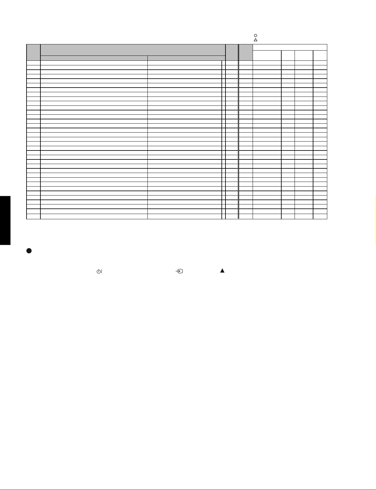
ADJ Function Max. Default
No.
PDM-4220
0 R DRIVE1 [RF/VIDEO/DSUB-COMP] COOL 255 255
1 G DRIVE1
2 B DRIVE1 [RF/VIDEO/DSUB-COMP] COOL 255 255
3 R DRIVE2 [RF/VIDEO/DSUB-COMP] NORMAL 255 255
4 G DRIVE2 [RF/VIDEO/DSUB-COMP] NORMAL 255 255
5 B DRIVE2 [RF/VIDEO/DSUB-COMP] NORMAL 255 255
6 R DRIVE3 [RF/VIDEO/DSUB-COMP] WARM 255 255
7 G DRIVE3 [RF/VIDEO/DSUB-COMP] WARM 255 255
8 B DRIVE3
9 R DRIVE4 [RF/VIDEO/DSUB-COMP] BLACK & WHITE 255 255
10 G DRIVE4 [RF/VIDEO/DSUB-COMP] BLACK & WHITE 255 255
11 B DRIVE4 [RF/VIDEO/DSUB-COMP] BLACK & WHITE 255 255
12 R DRIVE1 [DVI-PC/DVI-STB/DSUB-RGB] COOL 255 255
13 G DRIVE1 [DVI-PC/DVI-STB/DSUB-RGB] COOL 255 255
14 B DRIVE1 [DVI-PC/DVI-STB/DSUB-RGB] COOL 255 255
15 R DRIVE2 [DVI-PC/DVI-STB/DSUB-RGB] NORMAL 255 255
16 G DRIVE2
17 B DRIVE2
18 R DRIVE3 [DVI-PC/DVI-STB/DSUB-RGB] WARM 255 255
19 G DRIVE3 [DVI-PC/DVI-STB/DSUB-RGB] WARM 255 255
20 B DRIVE3 [DVI-PC/DVI-STB/DSUB-RGB] WARM 255 255
21 R DRIVE4 [DVI-PC/DVI-STB/DSUB-RGB] BLACK & WHITE 255 255
22 G DRIVE4 [DVI-PC/DVI-STB/DSUB-RGB] BLACK & WHITE 255 255
23 B DRIVE4 [DVI-PC/DVI-STB/DSUB-RGB] BLACK & WHITE 255 255
24 Brightness Center (CM) NTSC/PAL/ Multi picture 254 128
25 Brightness Center (CM) Scart-RGB(50/60Hz) 254 128
26 Brightness Center (CM) 480i/576i/480p/576p 254 128
27 Brightness Center (CM) 1080i-50/60/720p 254 124
28 Brightness Center (CM) DVI-PC 254 128
29 Brightness Center (CM) DVI-STB 254 128
30 Brightness Center (CM) DSUB-RGB 254 128
31 Brightness Center (CM) Expand DSUB-RGB (Reserved) 254 128
32 Brightness Center (CM) HDMI 254 128
33 Brightness center (CM) offset AV1 254 127
34 Brightness center (CM) offset AV2 254 127
35 Brightness center (CM) offset AV3 254 127
36 Brightness center (CM) offset AV4 254 127
37 Brightness center (CM) offset AV5 254 127
38 Brightness center (CM) offset DSUB-COMP 254 127
39 Color Center (CM) SD(YCbCr)(50Hz) 127 72
40 Color Center (CM) SD(YCbCr)(60Hz) 127 68
41 Color Center (CM) Scart-RGB(50/60Hz) 127 70
42 Color Center (CM) HD(YPbPr)(50/60Hz) 127 70
43 Color Center (CM) DVI-PC 127 64
44 Color Center
45 Color Center (CM) DVI-STB (1080i-50/60/720p) 127 62
46 Color Center
47 Color Center (CM) DSUB-RGB 127 64
48 Tint Center (CM) PAL 254 125
49 Tint Center (CM) Scart-RGB(50Hz) 254 121
50 Tint Center (CM) Scart-RGB(60Hz) 254 120
51 Tint Center (CM) SD(YCbCr)(50Hz) 254 123
52 Tint Center (CM) SD(YCbCr)(60Hz) 254 130
53 Tint Center (CM) HD(YPbPr)(50/60Hz) 254 135
54 Tint Center (CM) DVI-PC 254 128
55 Tint Center
56 Tint Center (CM) DVI-STB (1080i-50/60/720p) 254 128
57 Tint Center (CM) DVI-STB (VGA) 254 128
58 Tint Center (CM) DSUB-RGB 254 128
59 Center of Sharpness (Y-Enhancer Gain for HV) RF 31 10
60 Center of Sharpness (Y-Enhancer Gain for HV) VIDEO 31 15
61 Center of Sharpness (Y-Enhancer Gain for HV) Scart-RGB(50/60Hz) 31 14
62 Center of Sharpness (Y-Enhancer Gain for HV) 480i/576i 31 10
63 Center of Sharpness (Y-Enhancer Gain for HV) 480p/576p 31 15
64 Center of Shar
65 Center of Sharpness (Y-Enhancer Gain for HV) 1080i-50/60 31 10
66 Center of Sharpness (Y-Enhancer Gain for HV) TEXT(for split) 31 19
67 Center of Sharpness (Y-Enhancer Gain for HV) DVI-STB (480i/576i) 31 14
68 Center of Sharpness (Y-Enhancer Gain for HV) DVI-STB (480p/576p) 31 10
69 Center of Sharpness (Y-Enhancer Gain for HV) DVI-STB (720p) 31 6
70 Center of Sharpness (Y-Enhancer Gain for HV) DVI-STB (1080i-50/60) 31 10
71 Center of Sharpness (Y-Enhancer Gain for HV) DVI-STB (VGA) 31 10
72 Contrast Center (CM) RF 254 137
73 Contrast Center (CM) AV1 254 137
74 Contrast Center (CM) AV2 254 137
75 Contrast Center
76 Contrast Center (CM) AV4 254 137
77 Contrast Center (CM) AV5 254 137
78 Contrast Center (CM) DVI-PC 254 128
79 Contrast Center (CM) DVI-STB (With Setup) 254 149
80 Contrast Center (CM) DVI-STB (Without Setup) 254 128
81 Contrast Center (CM) DSUB-RGB 254 128
82 Contrast Center (CM) Expand DSUB-RGB (Reserved) 254 128
83 Contrast Center (CM) DSUB-COMP 254 137
84 Maximum Value of Contrast at REAL/NORMAL mode 254 188
85 Offset Value of Contrast data at SPLIT mode 120 53
86 Offset value of gain for Black Stretch function Except OFF/LOW/HIGH mode 63 32
87 Horizontal Enhance TEXT 3 3
88 Vertical Enhance TEXT 3 3
89 Horizontal filter SW [HHPF0] NTSC/480i 1 0
90 (Enhancer Gain ) [HHPF1] PAL/576i 1 0
91 [HHPF2] 480p/576p/1080i-50/60/720p
[RF/VIDEO/DSUB-COMP] COOL 255 255
[RF/VIDEO/DSUB-COMP] WARM 255 255
[DVI-PC/DVI-STB/DSUB-RGB] NORMAL 255 255
[DVI-PC/DVI-STB/DSUB-RGB] NORMAL 255 255
(CM) DVI-STB (480i/576i/480p/576p) 127 62
(CM) DVI-STB (VGA) 127 62
(CM) DVI-STB (480i/576i/480p/576p) 254 128
ADJ. Items Mode PWB PWB PWB PANEL
pness (Y-Enhancer Gain for HV) 720p 31 6
(CM) AV3 254 137
Value
10
: shoule be adjusted
: should be followed previous data
Changed Component
FORMATTER VIDEO TUNER PDP
14
ADJ Function
]
(
)[
]
[
]
[
]
[
]
)
[
]
[
]
p
[
]
p
[
]
g
]
(
)[
]
/
p
[
]
[
]
[
]
)
[
]
[
]
p
[
]
p
[
]
g
C
g
]
[
]
[
]
)
[
]
p
[
]
p
[
]
g
]
[
]
p
p
]
(
)[
]
p
]
[
]
p
)[
]
[
]
p
]
(
)[
]
[
]
[
]
p
)[
]
[
]
[
]
[
]
p
[
]
p
[
]
[
]
[
]
p
[
]
p
g
]
[
]
p
p
]
[
]
p
p
]
[
]
p
g
]
[
]
p
[
]
[
]
p
[
]
[
]
[
]
[
]
p
[
]
p
g
]
[
]
p
p
]
[
]
p
p
]
[
]
[
]
)
[
]
p
g
]
[
]
p
q
]
[
]
p
[
]
p
(
])
(
])
(
])
g
])
g
])
g
])
(
])
(
])
(
])
p
]
[30])
p
])
p
])
No.
92 Horizontal Coring Level [HECOR1
Enhancer Gain
93
94
95
96
97
98
99
100
101 Vertical Corin
102
Enhancer Gain
103
104
105
106
107
108
109
110 Enhancer
111 Corin
112
113
114
115
116
117 Corin
118
119 YFRNR in
120 HD-NTSC, HD-PAL
121 4
122
123 YFRNR in
124
125 CFRNR in
126 HD-NTSC, HD-PAL
127
128
129 CFRNR in
130
131 Vertical Enhancer Gain for Y/G
132
133
134
135 Vertical DSB Gain for Y/G
136
137
138 Vertical DSB Corin
139
140 Vertical Enhancer Cli
141
142 Vertical Cli
143
144 Vertical Non Linear Peakin
145
146 Horizontal Enhancer Gain for Y/R
147
148
149
150 Horizontal DSB Gain for Y/R
151
152
153 Horizontal DSB Corin
154
155 Horizontal Enhancer Cli
156
157 Horizontal Cli
158
159
160
161 Horizontal Non Linear Peakin
162
163 Horizontal HPF Peak Fre
164
165
166 Initial value of Contrast Extend 1 of Panel Life function 127 93
167 Interval time of correction time Extend 1 of Panel Life function 127 10
168
Additional value of Contrast Extend 1 of Panel Life function 127 1
169 Initial value of Contrast Extend 2 of Panel Life function 127 63
170 Interval time of correction time Extend 2 of Panel Life function 127 6
Additional value of Contrast Extend 2 of Panel Life function 127 1
171
172 Menu Init. Contrast
173 Menu Init. Contrast
174 Menu Init. Contrast
175 Menu Init. Bri
176 Menu Init. Bri
177 Menu Init. Bri
178 Menu Init. Color
179 Menu Init. Color
180 Menu Init. Color
181 Menu Init. Shar
182 Menu Init. Shar
183 Menu Init. Shar
Level[VECOR1
ain of VH for
Amplitude for Y/G[YC0R0
Amplitube for B-Y/B,R-Y/R[CC0R0
ut Gain(Main) 2pictures[MYNRG0
ut Gain(Sub
ut Gain(Main) 2pictures[MCNRG0
ut Gain(Sub
Offset Level[YVECLPL0
Offset Level for Y/R[YHECLPL0
htness(-31[0]+31[62
htness(-31[0]+31[62
htness(-31[0]+31[62
ADJ. Items Mode PWB PWB PWB PANEL
HECOR2
HECOR3
HECOR4
HECOR5'
HECOR5
HECOR6
HECOR7
HECORPC
VECOR2
VECOR3
VECOR4
VECOR5'
VECOR5
VECOR6
VECOR7
VECORPC
YC0R1
YC0R2
YC0R3
YC0R4
YC0R5
CC0R1
sub
ictures[MYNRG2
MYNRG3
YCNRG1
SUB
MCNRG2
MCNRG3
SCNRG1
YVEG1
YVEG2
YVEG3
YVDSBG1
YVDSBG2
for Y/G[YVDSBC0
YVDSBC1
for Y/G 0:LTI[YVECLP0
YVECLP1
YVECLPL1
YVNLP1
YHEG1
YHEG2
YHEG3
YHDSBG1
YHDSBG2
for Y/R[YHDSBC0
YHDSBC1
YHDSBC1
YHECLPL1
YHECLPL3
YHECLPL2
YHNLP1
YHHPF1
YHHPF2
-31[0]+40[71
-31[0]+40[71
-31[0]+40[71
-31[0]+31[62
-31[0]+31[62
-31[0]+31[62
ness(-15[0
ness(-15[0]+15[30
ness(-15[0]+15[30
MYNRG1
YCNRG0
MCNRG1
SCNRG0
YVEG0
YVDSBG0
for Y/G[YVNLP0
YHEG0
YHDSBG0
for Y/R 0:LTI[YHDSBC0
for Y/G[YHNLP0
. SW for Y/R[YHHPF0
~
~
~
~
~
~
~
~
~
+15
~
~
~
NTSC-RF 15 3
PAL-RF/Multipicture 15 2
NTSC-VIDEO 15 1
PAL-VIDEO 15 1
Scart-RGB(50/60Hz
480i/576i 15 2
480p/576
1080i-50/60/720
PC 15 1
NTSC-RF 15 1
Multi
PAL-RF
NTSC-VIDEO 15 1
PAL-VIDEO 15 1
Scart-RGB(50/60Hz
480i/576i 15 0
480p/576
1080i-50/60/720
PC 15 0
TEXT 31 0
NTSC/PAL-RF/Multipicture 7 7
NTSC/PAL-VIDEO 7 5
480i/576i/Scart-RGB(50/60Hz
480p/576
1080i-50/60/720
NTSC/PAL S-input 7 4
NTSC/PAL/480i/576i/ Multipicture 7 1
480p/576p/1080i-50/60/720
HD-except HD 7 1
HD-HD 7 4
NT-* /PAL-* 7 1
HD-* 7 4
2pictures 7 4
4pictures/12pictures 7 1
HD-except HD 7 3
HD-HD 7 4
NT-* /PAL-* 7 4
HD-* 7 4
2pictures 7 3
4pictures/12pictures 7 4
NTSC/PAL(-except RF)/480i/576i 15 15
480p/576
1080i-50/60/720
PAL(-RF)/ Multipicture 15 15
NTSC/PAL/480i/576i/ Multipicture 3 3
480p/576
1080i-50/60/720
NTSC/PAL/480i/576i/ Multipicture 7 7
480p/576p/1080i-50/60/720
NTSC/PAL/480i/576i/ Multipicture 1 1
480p/576p/1080i-50/60/720
NTSC/PAL/480i/576i/ Multipicture 15 15
480p/576p/1080i-50/60/720
NTSC/PAL/480i/576i/ Multipicture 63 0
480p/576p/1080i-50/60/720
NTSC/PAL(-except RF)/480i/576i 15 15
480p/576
1080i-50/60/720p-60 15
PAL(-RF)/ Multipicture 15 15
NTSC/PAL/480i/576i/ Multipicture 3 2
480p/576
1080i-50/60/720
NTSC/PAL/480i/576i/ Multipicture 7 7
480p/576p/1080i-50/60/720
NTSC/PAL/480i/576i/ Multipicture 1 0
480p/576p/1080i-50/60/720
RF/ Multipicture 15 4
NTSC/PAL-VIDEO 15 4
480i/576i/Scart-RGB(50/60Hz
480p/576p/1080i-50/60/720
NTSC/PAL/480i/576i/ Multipicture 63 0
480p/576p/1080i-50/60/720
NTSC/PAL/480i/576i/ Multipicture 3 2
480p/576
1080i-50/60/720
For Dynamic 71 62
For Natural 71 62
For Cinema 71 51
For Dynamic 62 31
For Natural 62 31
For Cinema 62 33
For Dynamic 62 36
For Natural 62 31
For Cinema 62 21
For Dynamic 30 20
For Natural 30 15
For Cinema 30 10
icture 15 8
Max.
Value
15 15
15 1
15 1
15 15
15 15
15 15
74
71
71
71
15 4
15 15
30
32
70
10
15 8
63 0
15 15
15
30
32
77
10
15 10
15 1
63 0
32
32
: shoule be adjusted
: should be followed previous data
Default
Changed Component
FORMATTER VIDEO TUNER PDP
PDM-4220
PDM-4220
15
PDM-4220
p.(
p.(
(
])
(
])
(
])
(
])
(
])
(
])
(
])
(
])
(
])
p
)
p
p)
p
p)
p
)
p
)
(CM)
p)
(CM)
p)
(CM)
p)
(CM)
p)
(CM)
p)
(CM)
p)
p
p
p
)L
p
p
L
p
p
p
p
L
p
L
ADJ Function Max. Default
No.
184 Menu Init. Color Temp.(Cool[0]/Normal[1]/Warm[2]/B&W[3])For Dynamic 3 0
185 Menu Init. Color Tem
186 Menu Init. Color Tem
187 Menu Init. Black stretch
188 Menu Init. Black stretch
189 Menu Init. Black stretch
190 Menu Init. YNR
191 Menu Init. YNR
192 Menu Init. YNR
193 Menu Init. LTI
194 Menu Init. LTI
195 Menu Init. LTI
196 Center of Shar
197 Center of Shar
198 Center of Shar
199 Center of Shar
200 Center of Shar
201 Color Center
202 Color Center
203 Color Center
204 Tint Center
205 Tint Center
206 Tint Center
207 Shar
208 Shar
209 Shar
210 Shar
211 Shar
212 Shar
213 Shar
214 Shar
215 Shar
216 Shar
217 Sharpness Gain(S.VIDEO)
Off[0]/Low[1]/Mid.[2]/High[3
Off[0]/Low[1]/Mid.[2]/High[3
Off[0]/Low[1]/Mid.[2]/High[3
ness Gain(RF) BG/DK/I Main 15 8
ness Gain(RF) M Main 15 8
ness Gain(RF
ness Gain(RF) L' Main 15 8
ness Gain(VIDEO) PA
ness Gain(VIDEO) NTSC3.58 Main 15 10
ness Gain(VIDEO) SECAM,B/W Main 15 8
ness Gain(VIDEO) NTSC4.43 Main 15 8
ness Gain(VIDEO) N-PA
ness Gain(VIDEO) M-PA
ADJ. Items Mode PWB PWB PWB PANEL
Cool[0]/Normal[1]/Warm[2]/B&W[3])For Natural 3 1
Cool[0]/Normal[1]/Warm[2]/B&W[3])For Cinema 3 2
Off[0]/Low[1]/Mid.[2]/High[3
Off[0]/Low[1]/Mid.[2]/High[3
Off[0]/Low[1]/Mid.[2]/High[3
Off[0]/Low[1]/High[2
Off[0]/Low[1]/High[2
Off[0]/Low[1]/High[2
ness(HV Enhancer Gain for Y) HDMI(480i/576i
ness(HV Enhancer Gain for Y) HDMI(480p/576
ness(HV Enhancer Gain for Y) HDMI(720
ness(HV Enhancer Gain for Y) HDMI(1080i-50/60
ness(HV Enhancer Gain for Y) HDMI(VGA
For Dynamic 3 2
For Natural 3 1
For Cinema 3 0
For Dynamic 2 0
For Natural 2 0
For Cinema 2 0
For Dynamic 3 2
For Natural 3 1
For Cinema 3 0
HDMI-YCbCr(50Hz:576i/576
HDMI-YCbCr(60Hz:480i/480
HDMI-YPbPr(1080i-50/60/720
HDMI-YCbCr(50Hz:576i/576
HDMI-YCbCr(60Hz:480i/480
HDMI-YPbPr(1080i-50/60/720
Main 15 8
Main 15 10
Main 15 8
Main 15 8
Main 15 7
Value
31 10
31 10
31 6
31
31 10
127 65
127 65
127 65
254 126
254 126
254 126
15218 Horizontal HPF Peak Frequency 720p-50 5
: shoule be adjusted
: should be followed previous data
Changed Component
FORMATTER VIDEO TUNER PDP
6
PDM-4220
Factory Reset
After all of the adjustments of main chassis are finished, perform FACTORY RESET.
Press the SUB-POWER(
more than 5 seconds.
The unit is set to factory settings.
) button, INPUT SELECT( ) button and button at the same time, and hold for
16
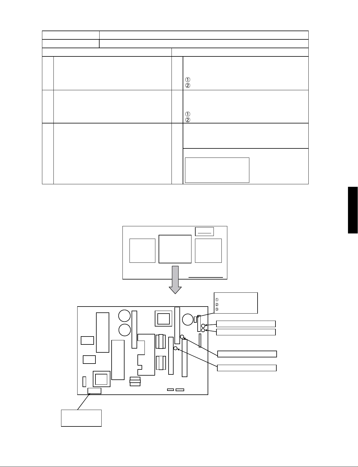
Item Power Unit Vs, Va Adjustment
Applicable Model All models
Preparation Procedure
(1) Turn on the set and perform
pre-heat run more than 1 min
on burn-in screen.
(2)
Receive full back pattern signal
(or Video silence signal;
but it will be automatically turned off
after a few seconds by power save function.)
(3) Connect voltmeter leads to Vs
(or V a) and GND test points of the power unit.
(1) Turn Vs ADJ to adjust Vs voltage
to be within ±0.1V of the value
specified in the label on the panel.
Adjust within ± 1V at Vs1
Adjust within ± 0.1V at Vs2
(2)
Turn Va ADJ to adjust Va voltage
to be within ±0.2V of the value specified
in the label on the panel.
Adjust within ± 1V at Va1
Adjust within ± 0.2V at Va2
Reconfirm that Vs voltage remains within
(3)
±0.1V of the specified value.
Readjust if itís outside of the margin.
Label example
<LOT>N6
Vs= 80.0V Va=60.0V
Vw=140.0V Vx=60.0V
PDM-4220
PDM-4220
Y-sus
Power
Supply
Unit
Label
X-sus
Panel Module
C
V
(Rear View)
sV
aV
DNG
niP
tseT aV / sV 99N
RV tnemtsujda esraoc sV:1sV
RV tnemtsujda enif sV:2sV
RV tnemtsujda enif aV:2aV
RV tnem
tsujda esraoc aV:1a
S
MADE IN THAILAND
5147FPM ataruM
******** N/
17
PDM-4220
Item
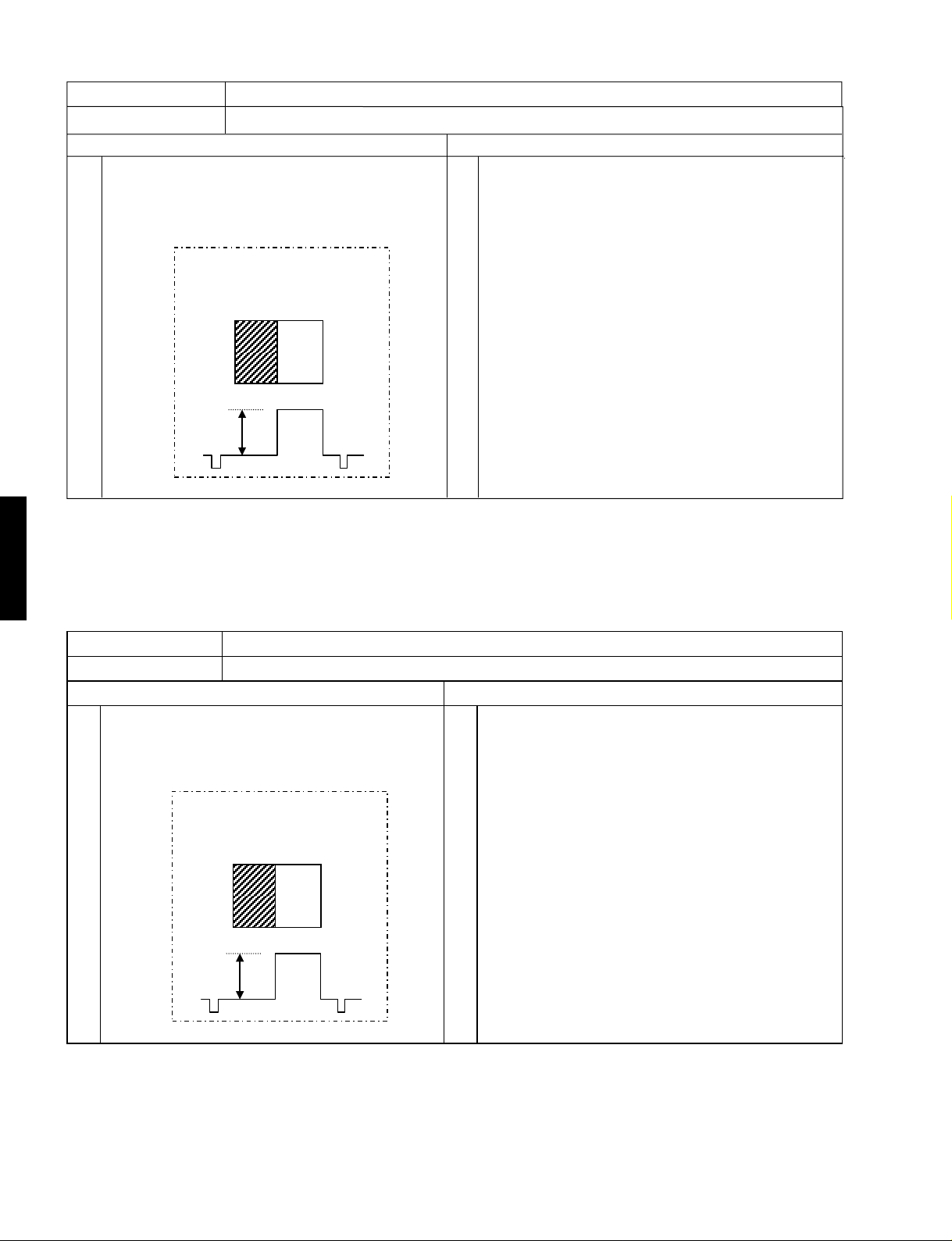
RGB Amplitude Adjustment (PC D-Sub input)
Applicable Model All models
Preparation Procedure
(1)
Input RGB amplitude adjustment signal of VGA
(60Hz) into RGB2 [D-sub] terminal.
Black pattern: Set pedestal level.
Characters must not be inserted
into this signal.
White
Black
0.7V
[Note] Never adjust without use of the specified signal.
If that were done by mistake, the picture would become abnormal in black level, contrast and color.
In this case, it will be recovered by re-adjustment in the specified way.
(1)
Receive PC signal (VGA [60Hz]), and indicate
Service Adjustment Menu.(Main)
(2)
Select No.652 of Service Adjustment Menu.
Press [OK] key more than 2 seconds to start the
automatic adjustment.
The adjustment completes when the OSD
reappears.
PDM-4220
Item
Applicable Model All models
(1) Input 576p or 480p adjustment signal
into AV4 terminal.
Black pattern: Set pedestal level.
Characters must not be inserted
into this signal.
[Note] Never adjust without use of the specified signal.
If that were done by mistake, the picture would become abnormal in black level, contrast and color.
In this case, it will be recovered by re-adjustment in the specified way.
RGB Amplitude Adjustment (Main/Sub)
Preparation Procedure
White
Black
0.7V
(1) Receive 576p or 480p adjustment signal on AV4
terminal input.
Indicate Service Adjustment Menu.
(2)
Select No.652 (RGB amplitude gain adjustment
Main) of Service Adjustment Menu.
Press [OK] key more than 2 seconds to start the
automatic adjustment.
The adjustment completes when the indication
[Auto Mode] at the bottom of the screen
disappears.
Select No.653 (RGB amplitude gain adjustment
(3)
Sub) of Service Adjustment Menu.
Press [OK] key more than 2 seconds to start the
automatic adjustment.
The adjustment completes when the indication
[Auto Mode] at the bottom of the screen
disappears.
18
 Loading...