

Page 1
PROFESSIONAL SERIES
POWER AMPLIFIERS
PC4002/4002M
OPERATING MANUAL
MODE D'EMPLOl
BEDIENUNGSANLEITUNG
YAMAHA
Vjum mramswd
.mm. «a»
. Oc
Page 2

ABOUT THIS MANUAL
The PC4002I4002M are high-power, high-quality power am
plifiers, designed for professional use. As with any power
amplifier, the overall performance of the PC4002j4002M de
pends to a certain extent upon the system design and instal
lation, as well as on its own capabilities. Hence, this manual
has been written with system installation in mind, as well as
describing the operation and performance of the
PC4002I4002M.
It is recommended that you read the whole of this manual, but
if you are adding a PC4002I4002M to an existing system, and
you are familiar with the operation of high-power amplifiers,
pages 3 through 4 contain all the information necessary for
basic connection and operation.
IMPORTANT NOTICE FOR THE UNITED KINGDOM
Connecting the Plug and Cord
IMPORTANT:Tlie wires in this mains lead are coloured in accordance with the following code:
Blue
Brown
As the colours of the wires in the mains lead of this apparatus may not correspond with the
coloured miu'kings identifying the terminals in your plug proceed as follows:
The wire which is coloured BLUE must be connected to the terminal which is marked with the
letter N or coloured BLACK.
The wire which is coloured BROWN must be connected to the terminal which is marked with the
letter L or coloured RED.
Making sure that neither core is connected to the earth terminal of the three pin plug.
NEUTRAL
LIVE
Page 3

PRECAUTIONS
• Avoid placing the unit in locations exposed to direct sunlight
or high temperatures, excessively high or low humidity, high
dust concentraion, or vibration.
• Be sure to connect to an AC power supply that meets the power
supply specifications listed on the rear of the unit.
• If there is any danger of lightning occurring nearby, remove the
power plug from the wall socket in advance.
• To avoid damaging your speakers and other playback equip
ment, turn off the power of all related equipment before making
connections.
• Do not use excessive force in handling control switches and
knobs.
• To avoid broken cords and short circuits, be sure to unplug all
connectors by grasping the respective plugs—NOT the cords.
• Remove the power plug from the AC mains socket if the unit
is not to be used for an extended period of time.
• Remove all plugs and connections if the unit is to be transported,
to prevent damage to the cords and jacks.
• Do not use solvents such as benzene or paint thinner to clean
the unit. Do not use insecticides or other pressurized spray
products in proximity to the unit. Wipe off the exterior with soft
cloth.
• The XLR (Cannon) type Input connectors are wired in the fol
lowing configuration: Pin 1: GROUND. Pin 2: HOT. Pin 3: COLD.
Ensure that all equipment connected to the PC4002/4002M
matches this wiring.
CONTENTS
INTRODUCTION ..................................................................... 2
FRONT PANEL ....................................................................... 3
REAR PANEL ......................................................................... 4
INSTRUCTIONS FOR CONNECTION OF
SPEAKER CABLES ............................................................... 5
GENERAL SPECIFICATIONS
PERFORMANCE GRAPHS
MOUNTING ............................................................................. 8
INSTALLATION PRECAUTIONS
CLEANING THE FAN FILTER ELEMENTS
BLOCK DIAGRAM
DIMENSIONS
..............................................................
.......................................................................
...............................................
...................................................
..........................................
........................
10
11
12
6
7
9
Page 4

INTRODUCTION
The PC4002/4002M are top-quality, high-power ampli
fiers, and with their impressive output combined with low
distortion figures, are ideally suited to studio monitoring
use, but at the same time are rugged enough to act ad
mirably as a professional amplifier where top quality is
required. Their features include:
Large, illuminated peak meters (PC4002IVI only) for
instant confirmation of output levels. In addition to the
meters, which provide a faster response than VU meters,
LED clip level indicators are provided for instant signalling
of clipping.
Front panel status indicators show the following:
if bridged (BTL) operation has been selected, high-speed
fan operation, and overload/power-up muting, as well as
a power indicator. The power switch is recessed into the
front panel, to prevent accidental resetting.
Decibel-calibrated input attenuators, detected for
extra accuracy. This makes for predictable and repeatable
setting-up on the road, and accurate input sensitivity ad
justments. In multi-amplifier setups, precise tracking be
tween amplifiers can be easily achieved. Input attenuator
knob locks prevent accidental resetting of levels.
Power-up muting for about six seconds after the power
has been turned on gives protection to speakers after
power-on, avoiding the "thump" which can easily blow
out cones.
Each channel is provided with input connectors
which are male and female balanced XLR, as well as bal
anced 1 /4-inch phone (using a TRS-type connector). This
allows convenient bridging to another amplifier, as well
as adapter-free connection to almost any mixer.
Robust mechanical design for practical use. The
PC4002/4002M is, of course, 19" rack-mountable, with
front handles which also help protect the controls and
meters. Though designed to be extremely reliable, and to
withstand the rigours of life on the road, if access is ever
needed to the interior of the unit, this has been made easy,
with bulb replacement, meter adjustment, etc, being pos
sible from the front panel. Power-cable hooks also act as
a support if the amplifier is used in a vertical position, and
four feet ensure airflow if the amplifier is shelf-mounted.
Multiple protection circuits safeguard the amplifier and
speaker system against abuse and faulty connections.
Twin power supplies and transformers for the power
amplifier stage add reliability and add quality to the sound
of the PC4002/4002M.
Bridged mode (BTL) from the A channel input is easily
obtained by the use of one switch on the back panel, and
connecting the ( + ) terminals of the CH-A and CH-B
speaker outputs to one speaker.
Figures that match the features. With a THD of less
than 0.005% at 215W into 80, and a figure which is still
less than 0.01% at 700W (mono) into 80, the
PC4002/4002M is one of the cleanest high-power am
plifiers on the market - making it especially useful for studio
monitoring operation. Channel separation, damping factor
and signal/noise figures are as good as or better than you
would normally expect from an amplifier of this calibre,
while the slew rate is an impressive 60V/ixS (stereo)-fast
enough to handle the fastest transients.
Speaker terminals are screw-post type, with the ability
to accept heavy-gauge speaker cable for maximum fidelity.
An automatic two-speed quiet twin-fan cooling
system prevents thermal overload, and cuts in at the low
speed when heat-sink temperatures exceed 60°C, and at
high speed above 80°C. The washable fan filters are re
movable from the front panel, eliminating the need to re
move the amplifier from a rack when the filters need to
be cleaned.
Page 5
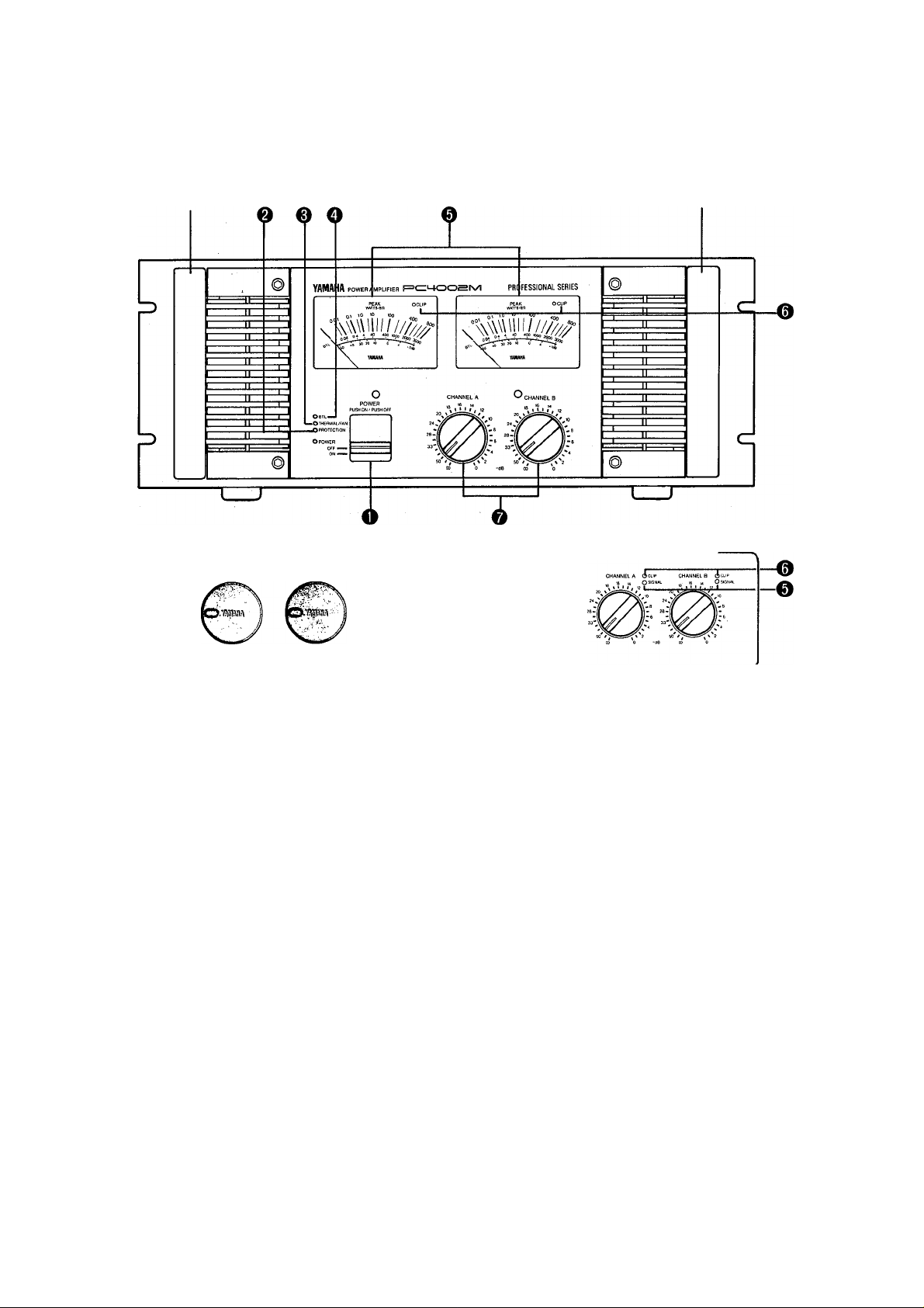
FRONT PANEL
Rack Handle
Q KNOB LOCKS’
Rack Handle
PC4002 ONLY
O POWER SWITCH/POWER INDICATOR (RED)
Push this switch to turn the power ON, and push it again
to turn the power OFF. The red power indicator will light
when power is supplied.
©PROTECTION INDICATOR (RED)
This indicator will illuminate under two sets of circum
stances: when power is first applied, a muting circuit is
in operation for about six seconds after power-up, to avoid
damage to speakers. This indicator will be lit at this time.
Additionally, if the protection circuitry is activated for any
reason (for instance, if a DC voltage exceeding ±2V ap
pears at the output terminal), the speaker outputs will be
shut off, and this indicator will go on. It will stay on for
as long as power is applied and the condition which caused
the protection circuit to activate still applies. Once the
condition has been remedied, the indicator will go off, and
normal operation will be resumed.
©THERMAL FAN INDICATOR (RED)
If the fans are operating at high speed (ie a heat-sink
temperature of 80°C has been attained), this indicator will
go on.
O BTL INDICATOR (GREEN)
This indicator will be lit if the BTL (mono bridging rtiode)
switch on the back panel has been set ON.
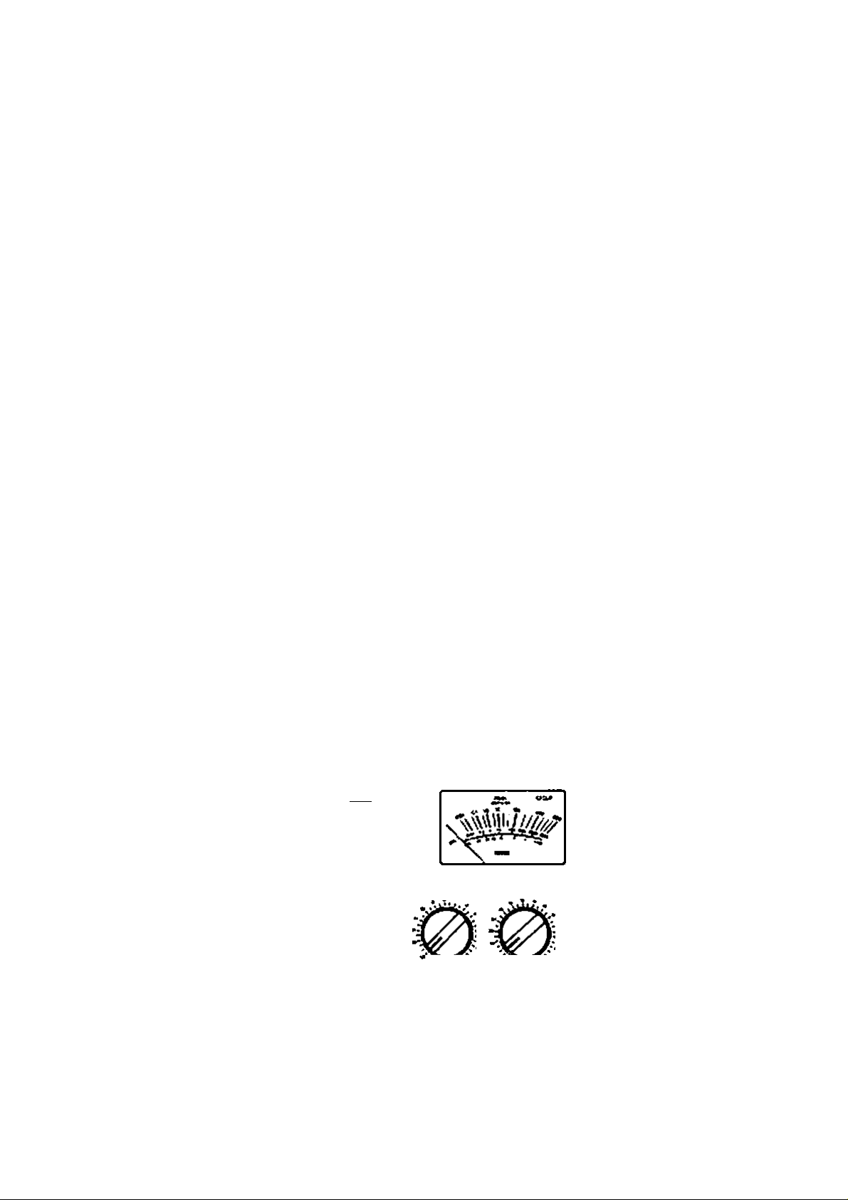
©PEAK METERS (PC 4002M ONLY)
These large illuminated meters give a peak reading of the
output level from the amplifier. The bulbs illuminating these
meters are replaceable without soldering from the front
panel. The meters' zero points may also be adjusted from
the front panel.
SIGNAL INDICATORS (GREEN) (PC4002 ONLY)
These signal indicators light when the output signal level
is 2V or more (in the frequency range 20Hz-20kHz) to
confirm the input signal.
©CLIP INDICATORS
These LED indicators light up when the output distortion
of the respective channel reaches a level of about 1 %.
© INPUT ATTENUATORS
These allow attenuation of the input signals in IdB cali
brations from 0-20dB, and in 2dB calibrations thereafter.
The controls are detented for a positive feel, and to help
with replicating settings.
© KNOB LOCKS (supplied)
Push these locks over the attenuation controls to prevent
accidental resetting of the levels. Pull them off again if you
need to reset the levels.
Page 6
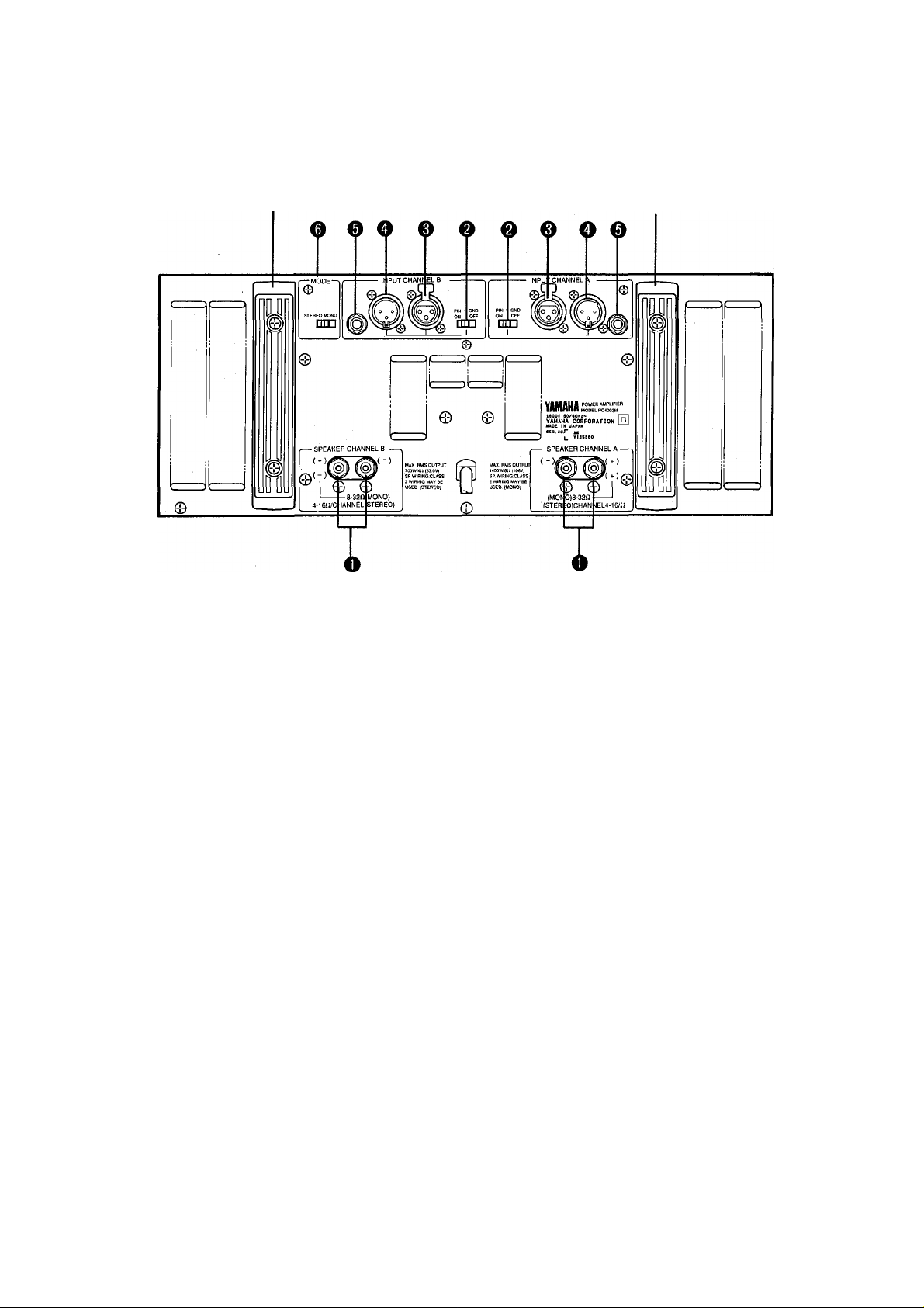
REAR PANEL
Cord Reel
Cord Reel
O SPEAKER TERMINALS (FOR EACH CHANNEL)
The red speaker terminal should be connected to the "+"
terminal of the speaker system, and the black terminal to
the channel. (In the above illustration, terminal covers
are not shown. See page 5)
©GROUND LIFT SWITCH (FOR EACH CHANNEL)
Connects or isolates the ground of XLR-pin 1. Usually left
ON. However, in some cases where ground loops are
causing hum, "lifting" the ground by turning this switch
OFF can interrupt the loop, thereby reducing hum.
©INPUT CONNECTORS (XLR-3-31)
These female input connectors are usually used as inputs.
They are wired: Pini =ground, Pin2 = hot, Pin3=cold.
Compatible connectors include ITT-Cannon XLR-3-12C,
Switchcraft 5C-1055A and Neutric NC3MX.
©INPUT CONNECTORS (XLR-3-32)
These male inputs duplicate the female input connectors
(same wiring), but are usually used for retransmitting the
input signal to other amplifiers. Compatible connectors
include ITT-Cannon XLR-3-11C, Switchcraft 5C-1056A
and Neutric NC3FX.
O PHONE INPUT CONNECTORS
These 1 /4-inch balanced TRS connectors accept balanced
and unblanced input signals. Tip=hot, Ring=cold,
Sleeve=ground.
© MODE SELECTOR SWITCH (BTL)
When set to MONO, this switch allows bridged (mono)
operation of the amplifier. The speaker terminals should
be connected to the" + " terminals of both channels (CH-A
to the speaker "+" and CH-B to the speaker "-"). When
using the PC4002/4002M in BTL (MONO) mode, con
nection should be made to CH-A input only.
Page 7
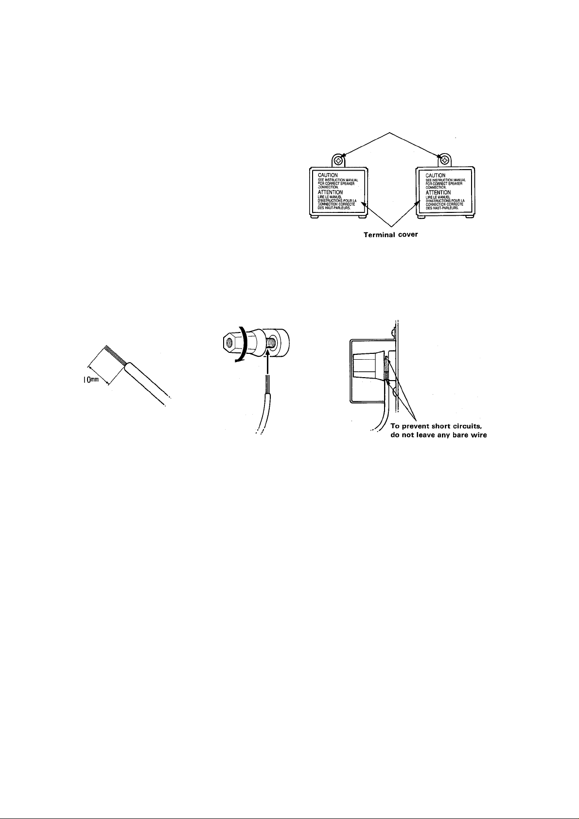
INSTRUCTIONS FOR CONNECTION OF SPEAKER CABLES
1. Make sure the power to the amplifier is OFF
2. Unscrew the covers over the speaker terminals
(Terminal covers are not installed in USA model)
3. For each cable, strip the insulation off one end of the speaker cable for about 10mm and twist and tin the wires. Pass the
tinned wires through the terminal hole and tighten the screw to grip the cable in place.
4. Replace the covers over the speaker terminals. Make sure that the speaker cables are fed down through the gap at the bottom
of the cover, and are not pinched or trapped by the covers.
Screw
5. If all other components are connected, turn on the amplifier.
expozed to touch the chassis or cover.
Page 8

GENERAL SPECIFICATIONS
These specifications are measured when the distortion of the AC Voltage is less than 1 %.
POWER OUTPUT LEVEL
Continuous average sine wave power with less than
0.05% THD. 20Hz - 20kHz
Stereo 8Q
Stereo 4Q ..................................................... 700W+700W
Mono 8Q................................................................. 1400W
FREQUENCY RESPONSE
Stereo, @ 8Q, 1W
Mono, @ 8Q, 1W
POWER BANDWIDTH
Stereo, 215W, 8Q, 0.1% THD
Stereo, 350W, 4Q, 0.1% THD
Mono, 700W, 8Q, 0.1% THD
TOTAL HARMONIC DISTORTION
Stereo, 215W, 8Q,
20Hz - 20kHz
Stereo, 350W, 4Q,
20Hz - 20kHz
Mono, 700W, 8Q,
20Hz-20kHz
INTERMODULATION DISTORTION
Stereo, 215W, 8fì,
60Hz:7kHz=4:1 .................................................. < 0.005%
Stereo, 350W, 4i2,
60Hz:7kHz=4:1
Mono, 700W, 8£î,
60Hz:7kHz=4:1
CHANNEL SEPARATION
(Input ATT max, input 600Q Shunt)
215W, 20Hz - 20kHz
@ 8Q...........................................
DAMPING FACTOR
1kHz @ 8ÎÎ
S/N
Input 600Î2 Shunt @ IHF-A .
RESIDUAL NOISE
ATT at min, @ 12.7kHz, -6dB/oct LPF
ATT at min, IHF-A network
SLEW RATE
Stereo, 8Q
Mono, 8Q
SENSITIVITY
ATT max, 400W 80 @ 1 kHz .
INPUT IMPEDANCE
Balanced/unbalanced
...................................................
....................
.....................
......................................
........................................................
.......................................................... <0.01%
...........
......................................... <0.01%
.....
............................................... < 0.01%
..................................
...................................
...................................
...................
10Hz - 50kHz OdB + ldB
10Hz - 50kHz 0dB±1dB
........................
.......................
............................
...........................
.............................
........................
.......................
......................................
...............
...........................
430W+430W
10Hz - 100kHz
10Hz - 100kHz
10Hz - 100kHz
............... < 0.005%
< 0.01%
> IIOdB
... +60V/).iS, Full Swing
±100V/pS, Full Swing
+4dB (1.23V)
> 80dB
> 300
< 75dB
< 80dB
>15kO
MAXIMUM VOLTAGE GAIN
Input ATT maximum, @ 1kHz
METERS (PC4002M ONLY)
Large illuminated
peak level meters x 2
INDICATORS
Green signal LED x
(PC4002 only)
Red clip LED x 2 ...
Green BTL LED x 1
Red thermal fan
LED X 1
Red protection
LED X 1
Red power LED x 1
PROTECTION CIRCUIT
Muting............................ 6 .sec (±2 sec) after power-on
DC sensing
PC limiter ............................................................ RL < 2Q
Thermal
COOLING FAN SPEED CIRCUIT
All temperatures refer to heat-sink temperature
Off to Low speed ..................................................... < 60°C
Low speed ................................Cuts in above 60°C. Cuts
High speed
POWER REQUIREMENTS
General model
US&Canadian models ................................ 120V AC 60Hz
POWER CONSUMPTION
General model
US&Canadian models
DIMENSIONS
(W X H X D)................................ 480 X 185.6 x 460 (mm)
WEIGHT
43 kg (94.8 lbs)
SUPPLIED ACCESSORIES
KNOB LOCK X2
3mm, ALLEN KEY x 1
.........................
...................................
.............................
................
2 Illuminate when signal
outputlevel goes above 2V.
.................
..................
.........
...............
...........
...........................
.......................................................
.......
.........
..............................
Illuminate when output
distortion from channel
Illuminates when BTL
(mono) mode is selected
Illuminates during high-
Illuminates during protection
or muting circuit operation
Illuminates when power on
....... DC +2V output voltage
> 100°C Heat Sink Temp
out when heat-sink temperature
Cuts in above 80°C. Drops
to low speed when heatsink
temperature drops below 65°C.
220/240V AC 50/60Hz
(18-7/g"x 7 5/i6"x 18-1/8")
-50dB - +7dB
0dB = 160W@8Q
exceeds approx 1 %
speed fan operation
drops below 45°C.
1600W, 2000VA
33.3dB
1600W
Page 9
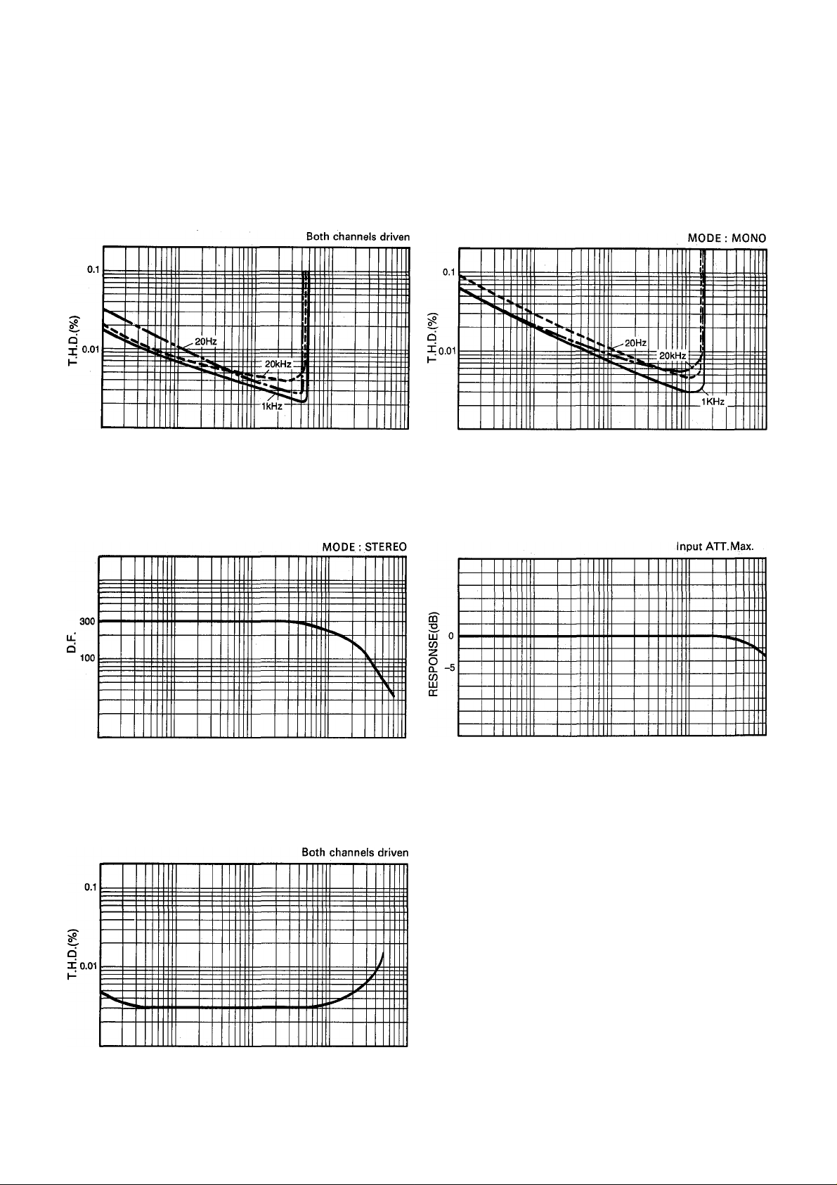
PERFORMANCE GRAPHS
T.H. DISTORTION VS. OUTPUT POWER
10 100 1K
POWER(W)
DAMPING FACTOR VS FREQUENCY
LOAD : 80
MODE : STEREO
LOAD : 80
T.H.DISTORTION VS OUTPUT POWER
10 100 IK
POWER(W)
FREQENCY RESPONSE
LOAD : 80
LOAD ; 80
MODE ; STEREO
OdB = 1W
100 IK 10K
T.H.D. VS FREQUENCY
100
FREQ.(Hz)
IK
FREQ.(Hz)
LOAD : 80
MODE ; STEREO
Po = 200W coni.
10K
20
100
CHANNEL SEPARATION
m
TO
-50
-90
100
1K
FREQ.(Hz)
IK
FREQ.(Hz)
10K
LOAD : 80
OdB = 200W
Measuring ch.
input 6000 shunt ATT.Max.
10K
Page 10
MOUNTING
When installing the PC4002/4002M, take care to avoid
radiant heat. Since the amplifier is fitted with twin fans
cooling system, do not block the front and rear panels.
SHELF MOUNTING
The PC4002M can be used on any flat, level surface as long
as there is adequate ventilation. Do not remove the
amplifier's feet as this would block airflow through the
bottom panel.
PC4002M
Air Flow
Shelf
Shelf mounting
permanent-installation rack mounting
The PC4002M can be mounted in any standard 19 elec
tronic equipment rack. The rear panel of the rack should
be left open to promote smooth airflow. Refer to the dia
grams below for the ideal cooling configuration.
* One vented blanking panel (1 U size) is necessary for
each PC4002M.
Air Flow
PORTABLE RACK MOUNTING
Road cases must be durable enough to withstand rough
handling and airline travel. Use a vented blanking panel
(1 Usize) at the bottom of the PC4002M (like that below).
li ii[ III II iiiiiii III III mil II mil II III III III
Unit : mm
Blanking panel
PC4002M- 1U size vented
blanking panel
Rack mounting with vented Blanking panels
YAMAHA VP1 Ventilation panel may he provided as an
optional accessory, (open area should be at least 35% of
total area)
---------------------------If unit(s) are to be used in a rack mounted installation, it
is recommended that Unit(s) should be used with vented
blanking panel(s) as above.
CAUTION!
---------------------------------------
Page 11
INSTALLATION PRECAUTIONS
• If you are using long speaker cables, use the heavy
gauge cables which are practical, in order to prevent
damping factor deterioration and/or power loss
through the cable. The PC4002/4002M's speaker
terminals allow you to use even the heavy gauge
cables.
• The PC4002/4002M produces 430W + 430W (into
Sohms) in stereo mode, and 1400W (into Sohms)
in mono mode, so use a speaker system which has
sufficient capacity to handle this power comfortably.
You can protect speakers of lower rated input capacity
than the rated output power of the PC4002/4002M
by connecting a fuse directly between the speaker
and amplifier (see illustration). When using a system
such as the one illustrated, follow the procedure on
this page to determine the capacity of the fuse to
be used.
PO = |2r
PO: Speaker continuous input power capacity (Noise
or RMS)
R: Nominal impedance of speaker
I: Required fuse capacity (A)
l = yP0/R
Example
Speaker continuous input power capacity
100W
Speaker impedance
Sohms
IF THE CUPPING AND PROTECTION CIRCUIT OPERATION INDICATORS LIGHT UP
Indicator
Clip Indicator
Protection indicator
Short in speaker termi
nal, amplifier output ter
minal, or cable
Amplifier overloaded
Heatsink temperature
exceeds 100°C
A DC voltage of more
than Ì2V has occurred
at the output terminals
Cause Check
Examine the places
where shorting may have
occurred
Make sure the speaker
system impedance is
more than 4ohms when
in stereo mode, and
Sohms when in mono
mode
Check the airflow and
take appropriate meas
ures to keep the
amplifier(s) cool
Contact your YAMAHA
distributor or service
center
In this example
l=yi00/8
l==3.5A
Protection Circuit Oper
ation
The PC limiter is in op
eration, protectiong the
power transistors
The same as above
The thermal protection is
in operation, protecting
the Power transistors.
The protection relay is in
operation, protecting the
speaker system
Page 12
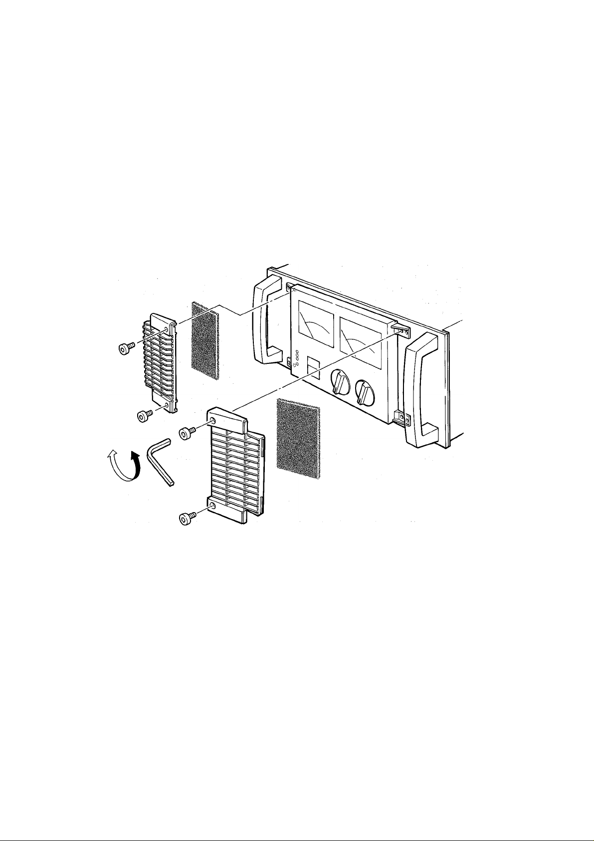
CLEANING THE FAN FILTER ELEMENTS
1. Make sure the power to the amplifier is OFF.
2. Remove the power plug from the AC mains socket.
3. Use the supplied 3mm Allen key (hex wrench) to remove
the four hex bolts securirig the front filter grilles.
4. Remove the filter elements, and wash in plain water. If
the filter elements are exceptionally dirty, detergent
(washing-up liquid) may be used.
5. Dry the filter elements thoroughly. NEVER REPLACE
THE FILTER ELEMENTS WHILE THEY ARE STILL
WETI
Replace the elements and front filter grilles. (The re
placement part number of the filter element is Vi 31380.)
10
Page 13
о
о
о
>
о
70
>
Page 14

DIMENSIONS
6.6
OUTPUT POWER VS POWER CONSUMPTION
(Mode : STEREO, Both channels driven)
-460-
-373.4-
- *-10.6
40
12
10 100 IK
OUTPUT POWER(W)
Page 15

AMPLIFICATEUR DE
PUISSANCE DE LA SERIE
PC4002/4002M
MODE D’EMPLOI
Page 16

UN MOT SUR CE MANUEL
Le PC4002 et le PC4002M sont des amplificateurs très puis
sants et de haute qualité, conçus pour une utilisation profes
sionnelle. Comme avec n'importe quel amplificateur de puis
sance, les performances du PC4002I4002M dépendent en
grande partie de la conception du système dans lequel il est
utilisé et de la manière dont il est installé. C’est pourquoi, tout
en décrivant l’utilisation et les performances du
PC4002I4002M, nous avons écrit ce manuel dans l’optique
de la mise en place d’un système.
Nous vous recommandons de lire ce manuel dans sa totalité,
mais si vous incorporez le PC4002I4002M dans un système
existant et que le fonctionnement d’un amplificateur de puis
sance de haut niveau vous est familier, les pages 2 à 3 conti
ennent toutes les informations nécessaires pour les branche
ments et l’utilisation.
PRECAUTIONS
• Eviter de placer l'appareil dans les endroits directement exposés
au soleil ou aux températures élevées, à l'humidité et à la
poussière, ou aux vibrations.
• S'assurer que la prise secteur utilisée délivre bien la tension
spécifiée à l'arrière de l'appareil.
• Л l'annonce d'un orage avec éclairs, il convient de débrancher
la fiche du cordon d'alimentation de la prise secteur.
• Pour ne pas endommager vos enceintes ou les autres éléments
de votre installation, il est indispensable d'éteindre tous les
appareils avant d'opérer des connections.
• Ne pas employer de force dans la manipulation des interrupt
eurs et des boutons.
• Pour éviter l'endommagement des cordons et les court-circuits,
ne déconnecter les appareils qu'en tirant sur la fiche elle-même,
jamais sur le cordon.
• Si l'on prévoit que l'appareil restera inutilisé pendant une
période assez longue, il est conseillé de débrancher le cordon
d'alimentation.
• Enlever toutes les fiches et connections avant un transport, afin
d'éviter de les endommager.
• Ne jamais utiliser de solvants tels que benzine ou térébenthine,
pour nettoyer l'appareil. Eviter également l'emploi d'insecticides
ou d'autres produits aérosols. Nettoyer l'extérieur avec un
chiffon doux.
• Les connecteurs d'entrée du type XLR (Cannon) sont câblé de
la façon suivante; Broche1:< masse >. Broche2: < chaud >.
BrocheS: < froid > . S'assurer que tout équipement corinecté
au PC4002/4002M corresponde à cette répartition.
TABLE DES MATIERES
INTRODUCTION .................................................................... 1
PANNEAU AVANT ................................................................. 2
PANNEAU ARRIERE ............................................................. 3
CONNEXIONS DES CÂBLES D'ENCEINTE ......................... 4
FICHE TECHNIQUE ............................................................... 5
GRAPHIQUES DES PERFQRMANCES ................................ 7
INSTALLATION ...................................................................... 8
PRÉCAUTIONS À PRONDRE À
L'INSTALLATION
NETTOYAGE DES ELEMENTS DE FILTER
DE VENTILATEUR
SCHEMA DE PRINCIPE ...................................................... 11
DIMENSIONS
.......................................................................
....................................................
...............................................
10
12
9
Page 17

INTRODUCTION
Le PC4002 et le PC 4002M sont des amplificateurs de
haute qualité extrêmement puissants et leur sortie im
pressionnante combinée à un taux de distorsion minime
en font ries amplificateurs idéauxl pour les systèmes de
contrôle des studios d'enregistrement, mais ils sont
également suffisamment solides pour remplir les fonctions
d'un amplificateur professionnel partout où la meilleure
qualité possible est requise. Leurs principales
caractéristiques sont :
Grands indicateurs de niveau de crête éclairés
(PC4002M uniquement) permettant une confirmation
instantanée des niveaux de sortie. Outre les indicateurs
qui offrent une réponse plus rapide que les VU- mètres,
des indicateurs de niveau d'écrêtage à DEL ont également
été prévus pour signaler immédiatement tout écrêtage.
Indicateurs de statut sur le panneau avant signa
lant: la sélection du mode de fonctionnement ponté (BTL),
le fonctionnement du ventilateur à grande vitesse et
l'activation du circuit d'étouffement à la mise sous tension
et en cas de surcharge, ainsi que la mise sous tension.
L'interrupteur d'alimentation est encastré dans le panneau
avant pour éviter toute actionnement accidentel.
Atténuateurs d'entrée calibrés en décibels, crantés
pour davantage de précision. Ce type de commande permet
d'effectuer rapidement les réglages prévisibles et habituels
et de régler avec précision la sensibilité d'entrée. Dans les
systèmes à plusieurs amplificateurs, le réglage des
différentes unités peut être plus facilement effectué. Le
bouton de l'atténuateur d'entrée se verrouille pour éviter
le déréglage accidentel des niveaux.
Interruption de la sortie de son à la mise sous
tension pendant environ six secondes après l'allumage
pour éviter qu'un "boum" ne fasse exploser les cônes des
haut-parleurs.
Les connecteurs d'entrée de chaque canal com
prennent des XLR symétriques mâles et femelles et des
"jack" de 1 /4" symétriques (type TRS) en parallèle. Ceci
permet un raccordement commode à un autre amplificateur
et une connexion sans adaptateur à pratiquement n'importe
quel type de table de mixage.
Les bornes des enceintes sont de type à visser. Elles
permettent la connexion de fils de gros calibre pour une
fidélité maximale.
Un système de ventilation automatique et silen
cieux à deux vitesses et deux turbines prévient tout
risque de surchauffe et s'enclenche en petite vitesse lorsque
la température à l'intérieur du châssis atteint 60° C et en
grande vitesse lorsque la température à l'intérieur du châssis
atteint 80° C. Les filtres du ventilateur sont lavables et
s'enlèvent par le panneau avant, ce qui élimine la nécessité
de sortir l'amplificateur de son emplacement lorsque les
filtres doivent être nettoyés.
Conception mécanique robuste pour une utilisation
pratique. Le PC4002 et le PC 4002M sont encastrables
en rack de 19" et possèdent des poignées à l'avant qui
contribuent également à protéger les commandes et les
potentiomètres. Bien que l'appareil soit de construction
solide et apte à résister aux rigueurs de la vie, lorsqu'une
intervention à l'intérieur est nécessaire, pour remplacer une
ampoule ou régler un potentiomètre, par exemple, elle peut
être facilement effectuée à partir du panneau avant. Les
crochets du câble d'alimentation ont également été prévus
comme support, pour le cas où l'amplificateur est utilisé
en position verticale et quatre pieds assurent la circulation
de l'air lorsque l'amplificateur est monté sur une étagère.
De nombreux circuits de sécurité protègent l'amplificateur
et les enceintes contre les mauvaises manipulations et
connexions et rendent superflue l'utilisation de fusibles
pour l'alimentation en courant continu.
Deux circuits d'alimentation et transformateurs
pour l'étage amplificateur augmentent la fiabilité et
la qualité de son du PC4002 et du PC4002M.
Le mode "ponté" (BTL) de l'entrée de la voie A s'obtient
aisément en utilisant un commutateur sur le panneau arrière
et en connectant les bornes (+) des sorties d'enceintes
CH-A et CH-B à une enceinte.
Performances à la hauteur des apparences. Avec
une distorsion harmonique totale inférieure à 0,005% à
215W sur 8iî, et une valeur toujours inférieure à 0,01 % à
700W (mono), sur 8Î2, le PC4002 et le PC4002M comptent
parmi les amplificateurs à haute puissance les plus nets
du marché-et constituent donc à ce titre les amplificateurs
idéaux poùr le contrôle du son en studio. Même lorsqu'ils
sont attaqués à 430W+430W sur 8Î2, la distorsion har
monique totale n'excède pas 0,05%. Les spécifications de
séparation des canaux, de facteur d'étouffement et de
rapport signal bruit sont toutes aussi bonnes et en tous
cas meilleures que ce que l'on peut attendre
d'amplificateurs de cette gamme, tandis que la vitesse de
balayage de la tension de sortie de 60V/)J,S (stéréo) est
suffisamment rapide pour traiter les transitoires les plus
rapides.
Page 18

PANNEAU AVANT
Poignée pour
Dispositifs de verrouillage
O
de boutons
Poignée pour
PC4002
UNIQUEMENT
O interrupteur MARCHE/ARRET et TEMOIN
(ROUGE)
Appuyez sur cet interrupteur pour mettre l'appareil sous
tension et appuyez une seconde fois pour mettre l'appareil
hors tension. Le témoin rouge associé s'allume lorsque
l'appareil est sous tension.
0TEMOIN DE PROTECTION (ROUGE)
Ce témoin s'allume dans deux circonstances : lorsque
l'appareil est mis sous tension, un circuit d'étouffement
entre en action pendant environ six secondes pour éviter
que les haut-parleurs ne soient endommagés et lorsque,
pour une raison ou une autre (par exemple, si un courant
continu excédant ±2V est présent à la borne de sortie),
les sorties vers les enceintes sont coupées. Dans le
deuxième cas, le témoin reste allumé tant que l'appareil
reste sous tension et que la cause de l'activation du circuit
de protection n'a pas disparu. Lorsque cette cause a été
éliminée, le témoin s'éteint et le fonctionnement reprend
normalement.
©TEMOIN DE FONCTIONNEMENT DU VENTI
LATEUR (ROUGE)
Ce témoin s'allume lorsque le ventilateur se met à foncti
onner en grande vitesse (c'est-à-dire si la température à
l'intérieur du châssis atteint 80°C).
©TEMOIN BTL (VERT)
Ce témoin s'allume si le commutateur BTL (mode mono
ponté), à l'arrière de l'appareil, est sur la position ON.
©indicateurs de CRETE (PC4002M UNIQUE
MENT)
Ces deux grands potentiomètres éclairés donnent le niveau
de sortie de l'amplificateur. Les ampoules qui éclairent ces
potentiomètres peuvent être remplacées sans soudage à
partir du panneau avant. Les points zéro peuvent également
être ajustés à partir du panneau avant.
TÉMOINS (VERTS) DU SIGNAL (PC4002 UNIQUEMENT)
Les témoins du signal s'allument lorsque le niveau de sortie
des signaux est de 2 V ou plus, dans une plage de 20 Hz
à 20 kHz, afin d'obtenir un niveau de signal adéquat.
©INDICATEURS D'ECRETAGE
Ces voyants à DEL s'allument lorsque la distorsion à la sortie
de la voie correspondante dépasse un niveau d'environ
1%.
©ATTENUATEURS D'ENTREE
Ces commandes permettent d'atténuer les signaux d'entrée
par incréments de 1 dB entre 0 et 20 dB et par incréments
de 2 dB au delà. Ces commandes sont crantées pour per
mettre une meilleure appréciation et accélérer le réglage.
©DISPOSITIFS DE VERROUILLAGE DE BOUTONS
(FOURNIS)
Pousser ces pièces sur les commandes d'atténuation pour
éviter une modification accidentelledes niveaux. Retirez-les
lorsque vous devez changer les niveaux.
Page 19

PANNEAU ARRIERE
Enrouleur pour cordon
Enrouleur pour cordon
0 BORNES D'ENCEINTES (POUR CHAQUE VOIE)
La borne d'enceinte rouge doit être connectée à la borne
" + " des enceintes et la borne noire, à la borne (Sur
l'illustration ci-dessus, les caches des homes d'enceintes
sont enlevées. Voir page 4)
©INTERRUPTEUR D'ISOLATION DE MASSE
(POUR CHAQUE VOIE)
Connecte ou isole la masse XLR broche 1. Généralement
laissé sur ON. Cependant, dans certains cas, lorsque des
boucles de masse provoquent un ronflement, l'isolation
de la masse en mettant cet interrupteur sur OFF peut in
terrompre la boucle et donc réduire le ronflement.
©CONNECTEURS D'ENTREE (XLR-3-31)
Ces connecteurs d'entrée femelles sont généralement
utilisés comme entrées. Ils sont câbles comme suit : Broche
1 = masse. Broche 2 = chaud. Broche 3 = froid. Les
connecteurs compatibles sont ITT-Cannon XLR-3-12C,
Switchcraft 5C-1055A et Neutric NC3MX
©CONNECTEURS D'ENTREE (XLR-3-32)
Ces entrées mâles dédoublent les connecteurs d'entrée
femelles (même câblage) mais ne sont pas utilisées pour
retransmettre le signal d'entrée à d'autres amplificateurs.
Les connecteurs compatibles sont ITT-Cannon XLR-311 C, Switchcraft 5C-1056A et Neutric NC3FX.
©CONNECTEURS D'ENTREE "JACK"
Ces connecteurs symétriques TRS de 1/4" acceptent et
retransmettent ies signaux d'entrée symétriques . Pointe
= chaud. Anneau = froid. Manchon = masse.
©SELECTEUR DE MODE (BTL)
Lorsque ce sélecteur est sur la position MONO,
l'amplificateur est ponté et fonctionne en mono. Les bornes
d'enceintes doivent être connectées aux bornes " + " des
deux canaux (CH- A à la borne “ + " et CH-B, à la borne
"-" de l'enceinte). Lorsque le PC4002 ou le PC4002M sont
utilisés en mode BTL (MONO), seule l'entrée CH-A doit
être connectée.
Page 20

CONNEXIONS DES CABLES D’ENCEINTE
1. S'assurer que l'interrupteur d'alimentation est sur OFF.
2. Dévisser les caches des bornes d'enceinte.
(Les bornes d'enceinte du modèle américain n'ont pas de caches.)
3. Dénuder l'extrémité du fil sur 10 mm et tordre les brins. Introduire la partie dénudée du fil dans l'encoche de la borne et
serrer la vis pour fixer le fil.
4. Remettre les caches sur les bornes en s'assurant que les fils passent librement par l'orifice situé au bas du cache et ne soient
ni pincés ni pris en piège par le cache.
Vis
5. Une fois que tous les composants sont connectés, mettre l'amplificateur sous tension.
le fil dénudé qui pourrait
être en contact avec le châssis
ou le couvercle.
Page 21

FICHE TECHNIQUE
* Ces spécifications sont établies lorsque les distorsions du courant alternatif sont inférieures à 1%.
NIVEAU DE PUISSANCE DE SORTE
Puissance sinusoïdale moyenne continue avec moins
de 0,05% de DHT, 20Hz - 20kHz
Stéréo 8Q ..................................................... 430W+430W
Stéréo 4D...................................................... 700W+700W
Mono 8Q................................................................. 1400W
REPONSE EN FREQUENCE
Stéréo @8Q1W
Mono @ 8Q 1W
BANDE PASSANTE EN PUISSANCE
Stéréo, 215W 8Q 0,1% DHT.............................10Hz - 100kHz
Stéréo, 350W, 4Q, 0,1% DHT...........................10Hz - 100kHz
Mono, 700W, 80, 0,1% DHT
DISTORSION HARMONIQUE TOTALE
Stéréo, 215W, 80,
20Hz - 20kHz
Stéréo, 350W, 40,
20Hz - 20kHz
Mono, 700W, 80,
20Hz - 20kHz........................................................... < 0,01 %
DISTORSION D'INTERMODULATION
Stéréo, 215W, 80,
60Hz:7kHz=4:1 .................................................. < 0,005%
Stéréo, 350W, 40,
60Hz:7kHz=4:1
Mono, 700W, 80,
60Hz:7kHz=4;1
SEPARATION DES CANAUX
(Entrée max. Entrée 6000 shunt)
215W, 20Hz - 20kHz
@80
.....................................................
BRUIT RESIDUEL
ATT min. f=12,7kHz -6dB/oct LPF
ATT min. réseau IHF-A
FACTEUR D'AMORTISSEMENT
1 kHz @ 80
RAPPORT SIGNAL/BRUIT
Entrée 6000 shunt @ IHF-A
..........................
.........................
.....................................................
.........................................................
.....
................................................ < 0,01%
......................................................
...........................................
.............................................................
10Hz - 50kHz 0dB±dB
10Hz - 50kHz OdB+dB
............................
...........................
..................................
10Hz - 100kHz
< 0,005%
>110dB
< 0,01%
< 0,01%
< 75dB
< 80dB
> 80dB
> 300
VITESSE DE BALAYAGE DE LA TENSION DE SORTIE
Stéréo, 8Î2
Mono, 8f2
SENSIBILITE
T max, 400W, 8Q @ 1kHz ............................ +4dB (1,23V)
IMPEDANCE D'ENTREE
Symétrique/Asymétrique...............................................15kO
GAIN DE TENSION MAXIMUM
Niveau d'entrée maximum, @ 1kHz
POTENTIOMETRE (PC4002M UNIQUEMENT)
Grands indicateurs de -50dB - + 7dB
niveau de crête éclairés x 2
INDICATEURS
DEL de signal verte x 2
(PC4002 uniquement)
DEL d'écrêtage rouge x 2
DEL BTL verte x 1
DEL de ventilation rouge x 1
DEL de protection rouge x 1
DEL d'alimentation rouge x 1
CIRCUIT DE PROTECTIQN
Etouffement ............. 6 sec (±2 sec) après la mise sous
Détection de courant continu
Limiteur PC............................................................ RL< 2fi
Température
...........................................
........
..................................................
..................
........................... S'allume lorsque le niveau de
sortie des signaux est de 2V ou plus.
....................
...................................S'allume lorsque le mode
............................................. S'allume lorsque le
.........
.................................................
.....................................
S'allume lorsque la distorsion à la
sortie de la voie atteint environ 1%.
BTL (mono) est sélectionné.
ventilateur tourne à grande vitesse.
S'allume lorsque le circuit de protection
ou d'étouffement du son est enclenché.
tension
.............................
. ±60V/|isàfond
+100V/IO.S à fond
...........................
0dB = 160W @ 80
S'allume lorsque
l'appareil est sous tension.
sortie en continu de ±2V
S: 100°C température
à l'intérieur du châssis
33,3dB
Tension de
Page 22

CIRCUIT DE MISE EN ROUTE DU VENTILATEUR DE REFROIDISSEMENT
Toutes les températures spécifiées s'entendent à
l'intérieur du châssis.
Ne tourne pas.......................................................... < 60°C
Petite vitesse
Grande vitesse
Modèle général
Modèles USA et Canada
CONSOMMATION
Modèle général
Modèles USA et Canada ........................... 1600W, 2000VA
DIMENSIONS
(L X H X P)
...............................
Désactivé lorsque la température à l'intérieur
......................
Passage au régime à petite vitesse lorsque la
température à l'intérieur du châssis descent
CARACTERISTIQUES D'ALIMENTATION
...........................
......................
........................................................
.....
........................... 480 X 185,6 x 460 (mm)
Activé au-delà de 60°C.
du châssis descend à moins de 45°C.
...... Activé au-delà de 80°C.
à moins de 65°C.
220/240V CA 50/60Hz
secteur 120V, 60Hz
1600W
(18-7/g"x 7 5/i6"x 18-1/8")
POIDS
43 kg (94,8 Ibs)
ACCESSOIRES FOURNIS
2 adaptateurs de blocage de boutons
1 clé Allen (3 mm)
Page 23

GRAPHIQUES DES PERFORMANCES
DISTORSION HARMONIQUE TOTALE/ PUISSANCE DE SORTIE
Charge : 8Í2
Mode : Stéréo
10 100 1K
PUISSANCE DE SORTIE(W)
FACTEUR D'AMORTISSEMENT PAR FREQUENCE
Charge : 8Í5
DISTORSION HARMONIQUE TOTALE/
PUISSANCE DE SORTIE
10 100 1K
PUISSANCE DE SORTIE(W)
REPONSE DE FREQUENCE
Charge : 8iî
Mode : Stéréo
0dB = 1W
Charge : 8£î
100
DHT PAR FREQUENCE
1K
FREQ.(Hz)
Charge : 8Í2
Mode : Stéréo
Po = 200W Cont.
10K
m
Ui
CO
2
O
CL
LU
CC
20
SEPARATION DES CANAUX
100
1K
FREQ.(Hz)
10K
Charge : 8iî
Odb = 200W
Mesure au canal
Entrée à la masse
100 1K 10K
FREQ.(Hz)
100 1K
FREQ.(Hz)
10K
Page 24

INSTALLATION
Eviter d'installer l'appareil près d'une source de chaleur.
L'amplificateur étant muni d'un double système de venti
lation, ne pas obstruer les panneaux avant ou arrière.
INSTALLATION SUR ÉTAGÈRE
Le PC4002M peut être utilisé sur toute surface plate et
horizontale, aussi longtemps que la ventilation reste suf
fisante. Ne pas retirer les pieds de l'amplificateur, sous
peine de bloquer le courant d'air qui passe par le panneau
inférieur.
PC4002M
Installation sur étagère
INSTALLATION PERMANENTE EN RACK
Le PC4002M peut être utilisé dans tout rack standard de
19 pouces. Le panneau arrière du rack doit être laissé ouvert
pour assurer une bonne ventilation. Pour connaître la
disposition idéale pour le refroidissement, se reporter aux
schémas ci-contre.
* Une plaque perforée de 1 U est nécessaire pour chaque
PC4002M.
INSTALLATION EN RACK PORTATIF
Les caissons de transport doivent être capables de sup
porter une manipulation intensive, ainsi que les voyages
en avion. Utiliser une plaque perforée (1 U), qui sera fixée
sous le PC4002M (comme illustré ci-dessous).
Unité; mm
Plaque perforée
PC4002M-
■■
ll■lll■ll■■llll■lil
Montage en rack avec plaques perforées
Plaque perforée
(1U)
Une plaque perforée YAMAHA VP1 peut être fournie en
option.
---------------------------Si des appareils doivent être installés dans un rack, il est
recommandé d'utiliser une plaque perforée comme celle
illustrée ci-dessus.
ATTENTION!
------------------------------------
Page 25

PRECAUTIONS A PRONDRE A L’INSTALLATION
Si les fils des enceintes acoustiques doivent être
longs, ne pas hésiter à prendre des fils d'un gros
calibre, afin d'éviter la diminution du facteur
d'amortissement ou encore une perte de puissance
au niveau des câbles. Les sorties d'enceintes du
PC4002/4002M vous permettent de choisir même
les calibres les plus gros.
Le PC4002/4002M produit 430 W + 430 W (sur 8
ohms) en mode stéréo, et 1400 W (sur 8 ohms) en
mode mono. Il est donc conseillé de choisir des en
ceintes acoustiques d'une capacité suffisante pour
supporter aisément cette puissance. Des enceintes
d'une capacité d'entrée inférieure à la puissance de
sortie du PC4002/4002M peuvent être protégées
par des fusibles connectés directement entre les
enceintes et l'amplificateur (voir illustration). Pour
un système, comme celui qui est illustré le calibre
des fusibles à utiliser, est déterminé de la façon sui
vante.
QUAND LE TÉMOIN DE PROTECTION OU LE TÉMOIN D'ÉCRÊTAGE S'ALLUME:
PO = I^R
PO: Capacité permanente d'entrée de l'enceinte
(souffle ou RMS)
R: Impédance nominale de l'enceinte
I: Calibre du fusible requis
l = yP0/R
Exemple
Capacité d'entrée de l'enceinte
100 W
Impédance de l'enceinte
8 Î2
Dans notre exemple
l=yi 00/8 14= 3,5 A
Témoins Cause Vérifications
Court-circuit au niveau
Témoin d’écrêtage (CLIP)
Témoin de protection
de la connection de
l’enceinte, de la sortie
de l’amplificateur ou du
câble
Surcharge de l’amplificateur
Température du dissi
pateur thermique supé
rieure à100°C
La tension de sortie a
dépassé i 2 V
Contrôler les emplace
ments où le court-circuit
a pu se produire
S’assurer que l’impé
dance des enceintes est
supérieureà4nen mode
stéréo, et de 8 Î2 en mode
mono pour assurer un
refroidissement efficace
Vérifier l’aération et
prendre les mesures
appropriées
Contacter votre distri
buteur YAMAHA ou notre
service clientelle
Circuits de protection
Le PC limiter protège les
transistors de puissance
Même protection
Le protecteur thermique
protège également les
transistors de puissance
Le relais protecteur
protège les enceintes
acoustiques
Page 26

NETTOYAGE DES ELEMENTS DE FILTRE DE VENTILATEUR
1. S'assurer que l'appareii est éteint.
2. Retirer la fiche de la prise secteur.
3. Utiliser une clé plate de 3 mm (fournie) pour déposer
les quatre boulons hexagonaux fixant les grilles avant
du filtre.
4. Retirer les éléments de filtre et les laver à l'eau claire.
Si les éléments sont particulièrement sales, du détergent
de vaisselle peut être utilisé.
5. Sécher les éléments dé filtre à fond. NE JAMAIS
REMETTRE LES ELEMENTS DE FILTRE ALORS
QU'ILS SONT ENCORE MOUILLES.
Remettre en place les éléments et les grilles avant des
filtres.
(Le numéro de pièce de l'élément de filtre est Vi 31380.)
10
Page 27

en
n
m
S
>
D
m
■O
ya
RI
VENTILATEUR CA
Page 28

DIMENSIONS
6.6
45
-460-
-373.4-
"iOf
PUISSE DE SORTIE/CONSOMMATiON D’ENERGIE
(Mode : Stéréo, Les deux canaux en service)
2L
-10.6
40
12
10 100 1K
PUISSANCE DE SORTIE(W)
Page 29

PROFESSIONELLE
ENDVERSTÄRKER
Deutsc
PC4002/4002M
BEDIENUNGSANLEITUNG
Page 30

zu DIESER ANLEITUNG
Der PC4002 und PC4002M sind leistungsstarke und ho
chwertige Verstärker für den professionellen Einsatz. Wie
immer richtet sich die Leistung des PC4002IPC4002M teil
weise nach der verwendeten Anlage und deren Verkabelung.
Deswegen wird in dieser Bedienungsanleitung von einem bes
timmten System ausgegangen, in das der PC4002jPC4002M
integriert wird.
Am besten lesen Sie sich die ganze Anleitung durch. Wenn
Sie den PC4002jPC4002M aber in ein existierendes System
integrieren und sich mit Verstärkern auskennen, brauchen Sie
nur die Seiten 2 und 3 zu lesen, wo alle wichtigen Hinweise
gegeben werden.
VORSICHTSMA§NAHMEN
• Vermeiden sie es, das Gerät der prallen Sonne, einer starken
Hitzequel le, extrem hoher oder niedriger Luftfeuchtigkeit, Vi
brationen oder Staub aussetzen.
• Beim Netzanschluß darauf achten, daß die Netzspannung den
Angaben auf der Rückseite des Creräts entspricht.
• Bei Gewittergefahr ist es ratsam, den Netzstecker auszuziehen.
• Alle angeschlossenen Geräte ausschalten, bevor irgendwelche
Anschlüsse hergestellt werden, um sowohl die Lautsprecher
als auch die anderen Teile der Anlage nicht zu beschädigen.
• Auf übertriebene Kraftanwendung an Schaltern und Knöpfen
verzichten.
• Anschlüsse sollten durch ziehen am Stecker, niemals durch
Ziehen am Kabel gelöst werden, sonst besteht Kabelriß- und
Kurzschlußgefahr.
• Es wird empfohlen, den Netzstecker auszuziehen, wenn das
Gerät eine Weile lang nicht mehr verwendet wird.
• Um Buchsen, Klinker und Kabel zu schützen, sollten vor einem
Transport alle Steckverbindungen gelöst werden.
• Verwenden Sie niemals Benzol, Verdünner oder andere
Lösungsmittel, um das Gerät zu reinigen. Vermeiden Sie
ebenfalls die Verwendung von Insectensprays und anderen
Druckgasprodukten in der Nähe der Anlage. Einfach das
Gehäuse mit einem weichen, trockenen Lappen abwischen.
• Die XLR (Gannon) Anschlüsse sind folgendermaßen verdrahtet:
Stift 1; < Masse > . Stift 2: < heiß > . Stift 3: < kalt > . Achten Sie
darauf, daß alle angeschlossenen Geräte entsprechend
ausgerüstet sind.
INHALT
EINLEITUNG .......................................................................... 1
FRONTSEITE
RÜCKSEITE
ANSCHLUß DER
ALLGEMEINE TECHNISCHE DATEN ................................... 5
LEISTUNGSKURVEN
AUFSTELLUNG ...................................................................... 7
VORSICHTS REGELN BEI
RENIGEN DER FILTERELEMENTE ...................................... 9
SCHACTUNGSDIAGRAMM ................................................. 10
ABMESSUNGEN
........................................................................
..........................................................................
LAUTSPRECHERKABEL....................................... 4
............................................................
INBETRIBNAHME
.................................................................
...................................................
11
2
3
6
8
Page 31

EINLEITUNG
Der PC4002/PC4002M ist ein Verstärker mit großer Aus
gangsleistung und hervorragenden Werten. Er empfiehlt
sich daher besonders für den Studioeinsatz, kann aber dank
seiner Robustheit auch mit Beschallungsanlagen verwen
det werden.
Große, beleuchtete Peak-Meter (nur auf dem
PC4002M) zeigen den Ausgangspegel an. Zusätzlich zu
den Metern, die schneller reagieren als VU-Meter, sind
CLIP LEDs vorhanden.
LEDs auf der Frontplatte für folgende Funktionen:
Im BTL Betrieb (Brücke) werden die hohe Ventilatorges
chwindigkeit, die Funktion der Einschaltverzögerung (und
Overload) sowie die Leistung angezeigt. Der Netzschalter
ist in der Frontplatte versenkt und kann daher nur bewußt
betätigt werden.
Dezibel-geeichte Stufen-Eingangsabschwächung.
Hierdurch kann unterwegs immer wieder derselbe Wert
eingestellt werden und die richtige Eingangsempfindlich
keit bleibt erhalten. Bei der Verwendung mehrerer
Verstärker kann die Anstiegsgeschwindigkeit also prob
lemlos angeglichen werden. Mit der Arretierung der
Abschwächungsregler vermeidet man ungewollte
Änderungen.
Einschaltverzögerung, die etwa 6 Sekunden aktiv ist
und die Boxen vor den gefährlichen Spannungsspitzen
beim Einschalten schützt.
Die Eingänge für jeden Kanal sind sowohl männliche
als auch weibliche symmetrische XLR-Anschlüsse sowie
parallele symmetrische TRS-1/4 Zoll-Klinken. Hierdurch
kann der Verstärker problemlos an weitere Verstärker an
geschlossen werden. Desweiteren ist der Vertärker mit fast
allen Mischpulten (adapterfrei) kompatibel.
Schraubanschlüsse für dicke Lautsprecherkabel, um den
besten Klang zu erzielen.
Robuste Konstruktion. Der PC4002/400M wird
natürlich im 19" Format geliefert und ist mit frontseitigen
Trägergriffen ausgestattet, die die Bedienungsoberfläche
schützen. Trotz der verläßlichen Konstruktion ist nicht
auszuschließen, daß irgendwann eine Sicherung oder eine
Birne ausgewechselt oder ein Meter neu justiert werden
muß. Auch hierzu hat man frontseitigen Zugriff. Die Haken
für das Netzkabel dienen gleichzeitig als vertikale Stützen.
Die vier Gummifüße garantieren den für die Belüftung
notwendigen Mindestabstand. Zahlreiche Schutzschal
tungen sichern den Verstärker und die Lautsprecher gegen
verkehrten Einsatz und fehlerhafte Anschlüsse und machen
Gleichstromsicherungen für die Spannungsquelle
überflüssig.
Zwei Spannungsquellen für die Verstärkerstufe
gewährleisten optimale Verläßlichkeit und Klangqualität
des PC4002/4002M.
Der Brückenbetrieb (BTL) für den A-Kanal kann mit
einem Schalter auf der Geräterückseite hergestellt werden.
In diesem Fall muß das Lautsprecherkabel an die (-1-)
Klemmen beider Ausgänge (A und B) angeschlossen
werden.
Die Angaben entsprechen der tatsä chlichen Leis
tung. Mit einem Klirrfaktor von weniger als 0,005% bei
215W an 8 ohm und einem Wert von 0,01% bei 700W
(Mono) an 8 ohm ist der PC4002/4002M einer der
"saubersten" Verstärker überhaupt - und deshalb voll
studiotauglich. Die Übersprechdämpfung, der
Dämpfungsfaktor und der Fremdspannungsabstand
übertreffen alle Erwartungen, die man an eine Endstufe
stellt. Die Anstiegszeit von 60 V/jisek. (Stereo) apituliert
auch vor den schnellsten Transienten nicht.
Automatischer geräuscharmer Zweigangventilator
verhindert Überhitzung des Verstärkers und funktioniert
im ersten Gang, sobald die Temperatur des Kühlkörpers
60°C beträgt. Der zweite Gang wird ab 80°C eingeschaltet.
Die waschbaren Filterelemente können frontseitig entfernt
werden, so daß man den Verstärker nicht jedesmal aus dem
Rack zu holen braucht.
Page 32

FRONTSEITE
Tragegriff
Tragegriff
o POWER TASTE/ANZEIGE (ROT)
Drücken Sie einmal auf diese Taste erneut, um den
Verstärker einzuschalten und erneut, um ihn wieder ausz
uschalten. Die rote POWER Diode leuchtet, sobald der
Verstärker eingeschaltet ist.
©PROTECTION ANZEIGE (ROT)
Diese Diode leuchtet in zwei Situationen: Beim Einschalten
des Verstärkers, um anzuzeigen, daß die
Einschaltverzögerung ca. 6 Sekunden lang aktiviert wird;
oder wenn eine Schutzschaltung funktioniert (wenn die
Gleichstromspannung an den Ausgängen z.B. ±2V
beträgt). Hierdurch werden die Lautsprecherausgänge
ausgeschaltet. Die Diode leuchtet so lange, bis die Span
nung wieder sinkt. Danach geht sie aus und die Laut
sprecher funktionieren wieder.
© FAN ANZEIGE (ROT)
Wenn die Ventilatoren im zweiten Gang funktionieren (d.h.,
wenn die Temperatur des Kühlkörpers 80°C beträgt), leu
chtet diese Diode.
©BTL ANZEIGE (GRÜN)
Diese Diode leuchtet im überbrückten Mono-Betrieb.
Hierfür müssen Sie den Schalter auf der Rückseite auf ON
stellen.
OPEGELANZEIGE (NUR PC4002M)
Diese beleuchteten Meter zeigen den Ausgangspegel des
Verstärkers an. Die Birnen dieser Meter können frontseitig
entnommen und ohne Löten ausgewechselt werden. Die
Meter können ebenfalls frontseitig justiert werden.
SIGNALANZEIGEN (GRÜN) (NUR PC4002)
Die Signaianzeigen leuchten auf, wenn der Signalaus
gangspegel 2 V oder mehr im Bereich von 20 Hz bis 20
kHz beträgt, um das Signal zu überwachen.
©CLIP ANZEIGE
Diese beiden Dioden leuchten, sobald die Verzerrung des
entsprechenden Kanals ca. 1 % beträgt.
O EINGANGSBEDÄMPFUNG
Hiermit dämpft man das Eingangssignal in IdB-Schritten
(0- 20dB) oder 2dB-Schritten (darüber). Die Regler
werden stufenweise eingestellt, was die Einstellung er
heblich erleichtert.
©ARRETIERUNG (GEHÖREN ZUM LIEFERUM
FANG)
Drücken Sie diese Arretierungen auf die Dämpfungsregler.
Hierdurch werden ungewollte Verstellungen vermieden.
Ziehen Sie sie wieder ab, wenn die Dämpfung geändert
werden soll.
Page 33

RÜCKSEITE
OSPEAKER ANSCHLÜSSE (FÜR BEIDE KANÄLE)
Die rote Klemme solltemitder" + " Buchse der Lautsprecher
verbunden werden und die schwarze mit dessen Ein
gang. (Die Schutzkappen der Lautsprecheranschlüsse sind
auf der vorangehenden Abbildung nicht dargestellt. Siehe
dazu Seite 4.)
0 GROÜND LIFT SCHALTER (FÜR BEIDE KANÄLE)
Ein-bzw. ausschalten der Masse (XLR-Stift 1). Sollte
normalerweise eingeschaltet sein. Wenn aber Brummsch
leifen festgestellt werden, können Sie eventuell mit diesem
Schalter abgestellt werden.
0 EINGÄNGE (XLR-3-31)
Am besten verwenden Sie diese weiblichen Eingänge. Die
Verdrahtung ist: 1 = Masse, 2= heiß, 3= kalt. Sie können
ITT-Cannon, XLR-3-12C, Switchcraft 5C-1055A und
Neutric NC3MX Stecker verwenden.
O EINGÄNGE (XLR-3-32)
Diese männlichen Anschlüsse haben dieselbe Funktion
wie die weiblichen (selbe Verdrahtung), dienen aber nor
malerweise für die Übertragung des Signals zu einem
weiteren Verstärker. Sie können ITT-Cannon, XLR-3-11C,
Switchcraft 5C-1056A und Neutric NC3FX Stecker ver
wenden.
0EINGÄNGSKLINKEN
An diese 1/4 Zoll-TRS-Klinken kann man symmetrische
Eingangssignale anlegen oder von hieraus weiterleiten.
Spitze= heiß, Ring= kalt, Mantel= Masse.
© MODE WAHLTASTE (BTL)
In der MONO Stellung befindet sich der Verstärker
überbrückten Monobetrieb. Schließen Sie die Lautspre
cherkabel in diesem Fall an die beiden "+" Klemmen der
Endstufe an (A-Kanal an die " + " und B-Kanal an die
Buchse des Lautsprechers. Im BTL (Mono) Bertrieb darf
die Box nur an die Klemmen des A-Kanals angeschlossen
werden.
Page 34

ANSCHLUß DER LAUTSPRECHERKABEL
1 Vergewissern Sie sich, daß das Gerät AUS-geschaltet ist.
2 Die Schutzkappen von den Lautsprecherausgängen losschrauben.
(USA Modelle sind nicht mit Schutzkappen versehen)
3 Entfernen Sie 10 mm der Isolierung vom Ende des Drahtes und drehen Sie die Adern zusammen. Führen Sie das abisolierte
Ende gerade in den Einlaß auf dem Ausgang ein und ziehen SiedieSchraubefest, umden Lautsprecherdraht fest anzubringen.
4 Die Schutzkappen wieder so anbringen, daß sich die Drähte frei durch den Schlitz am unteren Teil der Kappe bewegen
und weder gequetscht noch geklemmt werden.
Schraube
Kiemenabdeckung
5 Wenn alle Geräte angeschlossen sind, den Verstärker einschalten.
oder den Rahmenaufbau berühren
könnten, nie blank gelassen werden.
Page 35

ALLGEMEINE TECHNISCHE DATEN
* Diese Werte werden gemessen, wenn die Verzerrung der
AUSGANGSLEISTUNG
Sinusleistung mit einern Klirrfaktor von weniger als
0,05%, 20Hz - 20kHz
Stereo 8Q
Stereo 40 ..................................................... 700W+700W
Mono 80...........................................
FREQUENZGANG
Stereo, @ 80,1W 10Hz - 50kHz OdB + 1 dB
Mono, @ 80, 1W
LEISTUNGSBANDBREITE
Stereo, 215W, 80, Klirrf. 0,1 %
Stereo, 350W, 40, Klirrf. 0,1%
Mono, 700W, 80, Klirrf. 0,1%
KLIRRFAKTOR
Stereo, 215W, 80,
20Hz - 20kHz
Stereo, 350W, 40,
20Hz - 20kHz
Mono, 700W, 80,
20Hz - 20kHz........................................................... < 0,01%
INTERMODULATIONSVERZERRUNG
Stereo, 215W, 80,
60Hz:7kHz=4;1 .................................................. < 0,005%
Stereo, 350W, 40,
60Hz;7kHz=4:1 ...................................................... < 0,01%
Mono, 700W, 80,
60Hz:7kHz=4:1
ÜBERSPRECHBEDÄMPFUNG
(Größter Eingang, Eingang 600 Ohm Shunt)
215W 20Hz - 20kHz @ 80......................................... > 80dB
RESTGERÄUSCH
Dämpfung bei Mino,
f=12,7 kHz-6dB/0ktave LPF
Dämpfung bei Mino, IHF-A Netz .............................. < 80dB
DÄMPFUNGSFAKTOR
1 kHz @ 80................................................................ > 300
FREMDSPANNUNGSABSTAND
Eingänge 6000 Shunt @ IHF-A
ANSTIEGSGESCHWINDIGKEIT
Stereo 80
Mono 80
EMPFINDLICHKEIT
T Max, 400W 80 @ 1 kHz ............................. +4dB (1,23V)
EINGANSIMPEDANZ
Symmetrisch/unsymmetrisch
MAXIMALE SPANNUNGSVERSTÄRKUNG
Höchster Eingangspegel, @ 1kHz .............................. 33,3dB
...................................................
...................
.....................................................
.....
....................................................
......................................................
....................
....................
. 10Hz - 50kHz OdB ± 1 dB
....................
.....................
.....................
.....................................
.................................
±60V/n Sek. volle Schwingung
+100V/H Sek. volle Schwingung
........................................
430W+430W
.....................
10Hz - 10OkHz
10Hz - 100kHz
10Hz - 100kHz
< 0,005%
1400W
< 0,01%
< 0,01%
< 75dB
>110dB
15kO
Wechselstromspannung 1% nicht übersteigt.
METER (nur für den PC4002M)
Große beleuchtete Meter x 2 -50dB ~ +7dB
ANZEIGEN
Grüne SIGNAL LED x 2
(nur für den PC4002) signalausgangspegel
Rote CLIP LED x 2 .............................. Leuchten, wenn die
Grüne BTL Diode x 1
Rote FAN Diode x 1 .......................... Leuchtet im höheren
Rote PROTECT Diode
X 1 ...............................bei Einschaltverzögerung und im
Rote POWER Diode x 1 .............................. Leuchtet, wenn
SCHUTZSCHALTUNGEN
Einschaltverzögerung
Spannungsschutz
PC Schutz ........................................................... RL < 20
Überhitzungsschutz > 100°C Hitzewannen-Temperatur
VE NTI LATO R FU N KTIO N
Temperatur des Kühlkörpers
Bleibt aus bis
Kleine Geschwindigkeit
Große Geschwindikeit
SPANNUNG
Allgemeines Modell
USA und Kanada Modelle ...!
LEISTUNGSAUFNAHME
Aligmeines Modell .................................................... 1600W
USA und Kanada Modelle.......................... 1600W, 2000VA
ABMESSUNGEN
(B X H X D).....................................480 X 185,6 x 460 mm
GEWICHT
43 kg (94.8 Ibs)
MITGELIEFERTES ZUBEHÖR
2 Arretierungen
ImbußschzLissez (3mm)
.........................................................
........................
Verzerrung des Kanals ca. 1 % beträgt
...............................
.............................
..........
Gleichste ±2V Ausgangsspannung
.............................
Temperatur über 60 'C. Ausgeschaltet bei
...............................
Temperatur über 80 °C. Umschaiten auf
...................
0dB = 160W@8O
Leuchten, wenn der
2V oder mehr beträgt.
Leuchtet im BTL
(Mono) Betrieb
Ventilatorgang
Schutzschaltungsbetrieb
Endstufe eingeschaltet
6 Sek. ( + 2 Sek.)
nach Einschalten
< 60 °C
Eingeschaltet bei
unter 45 °C fallender Temperatur.
Eingeschaltet bei
kleine Geschwindigkeit bei unter
65 °C fallender Temperatur.
220V/240V AC, 50/60Hz
.....................
(18-7/8" X 7-5/16" X 18-1/8")
. 120V AC, 60Hz
Page 36

LEISTUNGSKURVEN
KLIRRFAKTOR/AUSGANGSLEISTUNG
KLIRRFAKTOR/AUSGANGSLEISTUNG
Last : 8i2
Betriebsart: Stereo
10 100 1K
AUSGANGSLEISTUNG(W)
DÄMPFUNGSFAKTOR nach Frequenz FREQUENZGANG
Last: 8i2
Last : 8fl
10 100 1K
AUSGANGSLEISTUNG(W)
Last: 8ii
Betriebsart: Stereo
OdB = IW
Eingang/Maximale Dämpfung
THD nach Fequenz
100
1K
FREQ.(Hz)
10K
Last: 8i2
Betriebsart: Stereo
Leistung : 200W kont
LU
I
ü
<
oc
Q.
CO
z
<
20
100
Übersprechdämpfung ^ 200W
m
•o
-50
-90
1K
10K
FREQ.(Hz)
Last : 8i2
Kanaimessung
Eingang 600 Ohm
Nebenschluß/Maximaie Dämpfung
100 1K 10K
FREQ.(Hz)
100
1K
FREQ.(Hz)
10K
Page 37

AUFSTELLUNG
Vermeiden Sie es, den PC4002/4002M in der Nähe einer
Hitzequelle hinzustellen. Da der Verstärker mit einer
Luftkühlung versehen ist, müssen die Vorderseite und die
Rückseite frei bleiben.
AUFSTELLUNG IM REGAL
Der PC4002M kann auf jeder ebenen Oberfläche aufgestellt
werden, solange für ausreichende Lüftung gesorgt ist.
Nicht die Füße des Verstärkers entfernen, da sonst die
Luftzufuhr zur Unterseite blockiert wird.
PC4002M
__ ____ __
3.^
______ _ _ _
-■r; - ». -■
/y^i. -/
i ' = ^'~
|o" 1
\
: W ' |o 1
c:
er
Luftfluß
Luftfluß
o|
p
p
o|
Aufstellung im Regal
s ;•
'X;"_ Xf’TT' '- 1 r tE' ii' ~]
-Ci]
-'i
-CD
.
Regal
PERMANENTE AUFSTELLUNG IN RACK
Der PC4002M kann in jedem normalen 19-Zoll-Rack für
elektronisches Equipment aufgestellt werden. Die
Rückplatte des Racks muß offen bleiben, um gute Lüftung
zu gewährleisten. Siehe Abb. rechts betr. beste Anordnung
für die Kühlung.
* Eine gestanzte Abdeckplatte (1 U) pro.PC4002IVI wird
benötigt.
TRANSPORTABLE AUFSTELLUNG IM RACK
Transportkästen müssen robust genug sein, um rauhe
Handhabung und Lufttransport zu überstehen. Eine ge
stanzte Abdeckplatte (1U) unter dem PC4002M (wie
nachfolgend dargestellt) anbringen.
■ ■ ■ ■
Einheit; mm
Abdeckplatte
PC4002M-
Rackeinbau mit lüftenden Abdeckplatten.
Abdeckplatte
(1U)
YAMAHA VP1 Abdeckplatten sind als Zubehör erhältlich.
----------------------------
VORSICHT!
-------------------------------------
Wenn die Einheit(en) in einem Rack verwendet wird
(werden), empfehlen wir den Einsatz einer Abdeckplatte
wie oben gezeigt.
Page 38

VORSICHTSREGELN BEI INBETRIEBNAHME
Falls lange Lautsprecherkabel verwendet werden,
sollten dicke Kabel bevorzugt werden, um
Dämpfungsfaktorverluste oder Energieverlust zu
vermeiden. Die PC4002/4002M Lautsprecher
ausgänge erlauben die Verwendung selbst dickster
Kabel.
Der PC4002/4002M leistet 430 W + 430 W (8 Ohm)
bei Stereogebrauch und 1400 W in Mono. Das
Lautsprechersystem sollte daher genügend Kapazität
haben, um diese Leistung zu verkraften. Sie können
auch Lautsprecher mit einem geringeren
Leistungsvermögen durch eine zwischen Laut
sprecher und Verstärker angebrachte Sicherung
schützen. Wenn Sie ein System wie das Abgebildete
benutzen, richten Sie sich am besten nach folgender
Methode, um die richtige Sicherungs- stärke zu er
rechnen.
I^R
PO
PO: kontinuierliches
Lautsprecherleistungsvermögen (Rauschleis
tung oder RMS)
R: Nominalimpedanz der Lautsprecher
I: benötigte Sicherungsstärke(A)
l = yP0/R
Beispiel
kont. Lautsprecherleistungsvermögen
100W
Lautsprecherimpedanz
80 hm
FALLS DIE ÜBERLASTUNGS-UND ÜBERSTEUERUNGSANZEIGEN AUFLEUCHTEN
Schutzanzeige Ursache Überprüfungen
Kurzschluß am Anschluß-
Übersteuerungsanzeige
Überlastungsanzelge
punkl eines Laut
sprechers oder des
Verstärkers, oder im Ka
bel.
Verstärkerüberlastung
Hitzewannentemperatur
übersteigt 100°C
Die Gleichstromspan
nung zwischen den
Anschlüssen hat -i- 2 V
überstiegen.
Stellen, wo der Kurz
schluß hätte stattfinden
können.
Die Lautsprecherimpe
danz ist über 4 Ohm
(Stereo) oder 8 Ohm
(Mono).
Ausreichende Luftzufuhr
gewährleisten. Treffen
Sie die nötigen Maßnah
men, um den Verstärker
kühl zu halten.
Wenden Sie sich an Ihren
YAMAHA-Händler oder
unseren Kundendienst.
Unserem Beispiel nach
I=-/100/8 also 1= 3,5 A
Schutzschaltungsfunk
tionen
Der PC limiter schützt die
Leistungstransistoren
Selbe Schutzschaltfunk
tion
Der Überhitzungsschutz
sichert ebenfalls die
Leistungstransistoren
Die Gleichstromstabili
sierung sichert die Laut
sprecher.
Page 39

REINIGEN DER FILTERELEMENTE
1. Sicher sein, daß der Verstärker ausgeschaltet ist.
2. Den Netzstecker ausziehen.
3. Lösen Sie die vier Schrauben des Filtergrills mit einem
3mm Imbusschlüssel (mitgeliefert).
4. Die Filterelemente entnehmen und in klarem Wasser
auswaschen. Falls die Elemente extrem schmutzig sind,
darf auch Abwaschmittel verwendet werden.
5. Die Elemente danach vollständig trocknen (lassen).
SETZEN SIE NIEMALS NASSE FILTERELEMENTE EINI
Bringen Sie die Elemente und den Grill wieder an. (Die
Ersatzteil nummer des Filterelements ist Vi 31380.)
Page 40

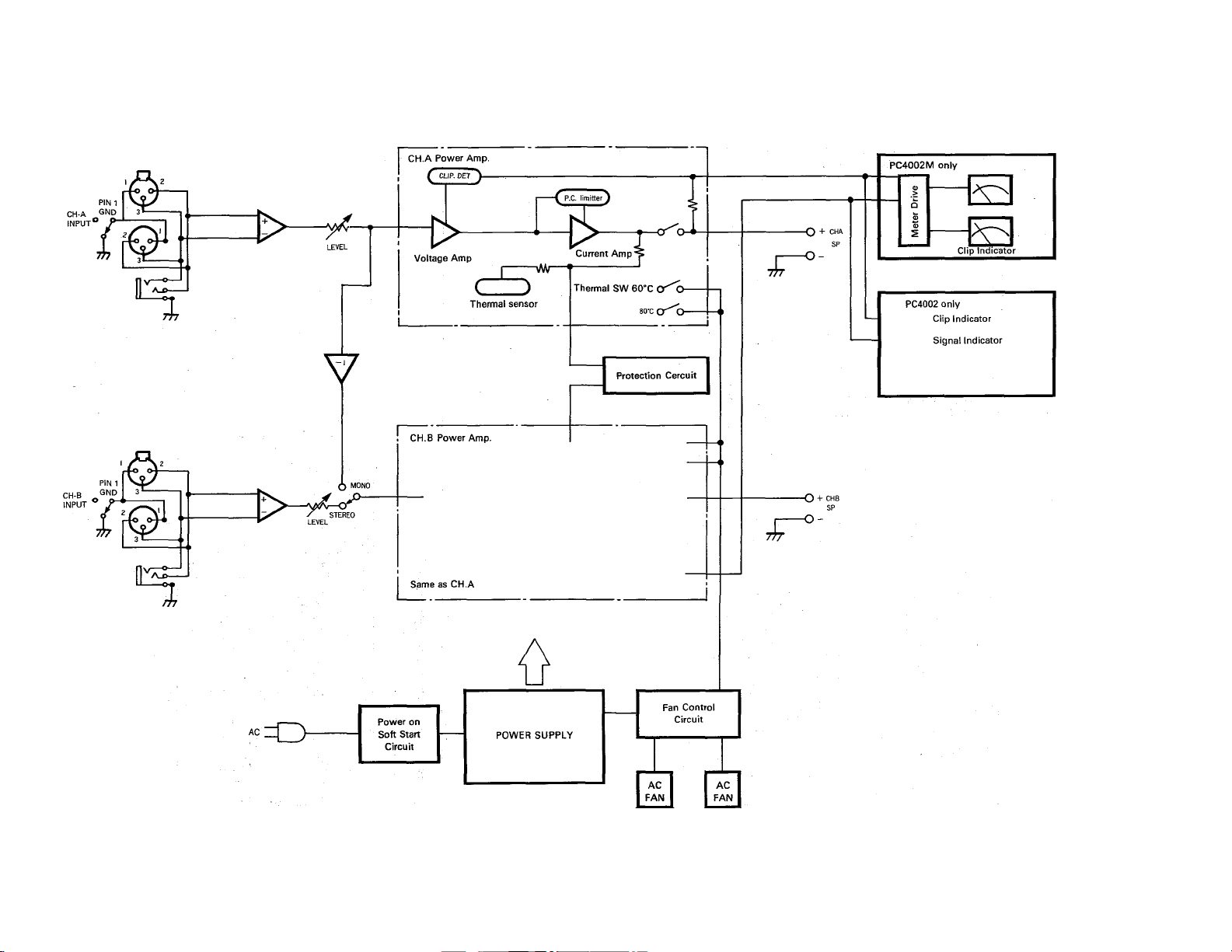
EINGANG ^ GND
KANAL
PIN
■ f^
o
X
>
r-
-I
c
KANAL A Leistungsverstärker
( CUP. DET^)-
1>—
PEGEL ,
Spannungsver
stärker
C_D
Thermosensor
1
I—c
-\Wr
PC Begrenzer
Stromver
stärker
-cr^>-
eoxcr'^o-
80-C Cr^O-
-O + Kanal A
SI
-O-
Nur PC4002M
o
3
9
CB O
o »
C o
S “
:5 0
a c
NurPC4002
Übersteuerungsanzeige
Signalanzeige
Übersteuerungsanzeige
z
o
D
>
o
90
>
s
3
EINGANG^Gf^
KANAL B
PIN 1
'[On
№:
1
Netzanschluss
V
(}) MONO
/ STEREO
Kanal B Leistungsverstärken
Siehe Kanal /
Spannungs
verzögernder
Schaltkreis
Stromversorgung
Schutzschaltung
Ventilatorsteuer
schaltung
Wechselstromventi lator
-O + Kanal B
Page 41

ABMESSUNGEN
AUSGANGSLEISTUNG/LEISTUNGSAUFNAHME
(Betriebsart: Stereo, Beide Kanäie angesteuert)
10 100 1K
AUSGANGSLEiSTUNG(W)
11
Page 42

SERVICE
The PC4002/4002M is supported by Yamaha’s worldwide network of
factory trained and qualified dealer service personnel. In the event of
a problem, contact your nearest Yamaha PC4002/4002M dealer. For the
name of the nearest dealer, contact one of the Yamaha offices listed
below.
ENTRETIEN
L’entretien la console PC4002/4002M est assuré par le réseau mondial
YAMAHA de personnel d’entretien qualifié et formé en usine des con
cessionnaires. En cas de problème, prendre contact avec le concessi
onnaire YAMAHA le plus proche. Se référer à la liste ci-dessous.
KUNDENDIENST
Für den PC4002/4002M steht das weltweite YAMAHA Kundendienst netz
mit qualifiziertem, werksgeschultem Personal zur Verfügung. Bei
Störungen und Problemen wenden Sie sich bitte en Ihren nächsten
YAMAHA PC4002/4002M-Händler. Die hiernach aufgeführten YAMAHA-Niederlassungen teilen Ihnen gerne die Namen und Adressen der
YAMAHA-Händler in Ihrer Nähe mit.
Page 43

Y AM AH A
VI50040 R1 1 CR 93 04 200 CR Printed in Japan
YAMAHA CORPORATION
P.O.Box 1, Hamamatsu, Japan
 Loading...