

Page 1

DIGITAL RECORDING CONSOLE
E
Page 2

ADVARSEL!
Lithiumbatteri—Eksplosionsfare ved fejlagtig
håndtering. Udskiftning må kun ske med batteri
af samme fabrikat og type. Levér det brugte
batteri tilbage til leverandoren.
VARNING
Explosionsfara vid felaktigt batteribyte. Använd
samma batterityp eller en ekvivalent typ som
rekommenderas av apparattillverkaren.
Kassera använt batteri enligt fabrikantens
instruktion.
VAROITUS
Paristo voi räjähtää, jos se on virheellisesti
asennettu. Vaihda paristo ainoastaan
laitevalmistajan suosittelemaan tyyppiin. Hävitä
käytetty paristo valmistajan ohjeiden
mukaisesti.
FCC INFORMATION (U.S.A.)
1. IMPORTANT NOTICE: DO NOT MODIFY THIS UNIT!
This product, when installed as indicated in the instructions contained in this manual, meets FCC requirements. Modifications not expressly approved by Yamaha
may void your authority, granted by the FCC, to use the product.
2. IMPORTANT: When connecting this product to accessories and/or another product use only high quality shielded cables. Cable/s supplied with this product MUST
be used. Follow all installation instructions. Failure to follow instructions could void your FCC authorization to use this product in the USA.
3. NOTE: This product has been tested and found to comply with the requirements listed in FCC Regulations, Part 15 for Class “B” digital devices. Compliance with
these requirements provides a reasonable level of assurance that your use of this product in a residential environment will not result in harmful interference with
other electronic devices. This equipment generates/uses radio frequencies and, if not installed and used according to the instructions found in the users manual, may
cause interference harmful to the operation of other electronic devices. Compliance with FCC regulations does not guarantee that interference will not occur in all
installations. If this product is found to be the source of interference, which can be determined by turning the unit “OFF” and “ON”, please try to eliminate the
problem by using one of the following measures:
Relocate either this product or the device that is being affected by the interference.
Utilize power outlets that are on different branch (circuit breaker or fuse) circuits or install AC line filter/s.
In the case of radio or TV interference, relocate/reorient the antenna. If the antenna lead-in is 300 ohm ribbon lead, change the lead-in to coaxial type cable.
If these corrective measures do not produce satisfactory results, please contact the local retailer authorized to distribute this type of product. If you can not locate the
appropriate retailer, please contact Yamaha Corporation of America, Electronic Service Division, 6600 Orangethorpe Ave, Buena Park, CA 90620
* This applies only to products distributed by YAMAHA CORPORATION OF AMERICA.
IMPORTANT NOTICE FOR
THE UNITED KINGDOM
Connecting the Plug and Cord
WARNING: THIS APPARATUS MUST BE EARTHED
IMPORTANT: The wires in this mains lead are coloured in accordance with
the following code:
GREEN-AND-YELLOW : EARTH
BLUE : NEUTRAL
BROWN : LIVE
As the colours of the wires in the mains lead of this apparatus may not
correspond with the coloured markings identifying the terminals in your
plug, proceed as follows:
The wire which is coloured GREEN and YELLOW must be connected to
the terminal in the plug which is marked by the letter E or by the safety earth
symbol or coloured GREEN and YELLOW.
The wire which is coloured BLUE must be connected to the terminal which
is marked with the letter N or coloured BLACK.
The wire which is coloured BROWN must be connected to the terminal
which is marked with the letter L or coloured RED.
* This applies only to products distributed by YAMAHA KEMBLE
MUSIC (U.K.) LTD.
NEDERLAND
● Dit apparaat bevat een lithium batterij voor geheugen back-
up.
● Raadpleeg uw leverancier over de verwijdering van de batterij
op het moment dat u het apparaat ann het einde van de
levensduur afdankt of de volgende Yamaha Service Afdeiing:
Yamaha Music Nederland Service Afdeiing
Kanaalweg 18-G, 3526 KL UTRECHT
Tel. 030-2828425
● Gooi de batterij niet weg, maar lever hem in als KCA.
THE NETHERLANDS
● This apparatus contains a lithium battery for memory back-
up.
● For the removal of the battery at the moment of the disposal
at the end of the service life please consult your retailer or
Yamaha Service Center as follows:
Yamaha Music Nederland Service Center
Address: Kanaalweg 18-G, 3526 KL
UTRECHT
Tel: 030-2828425
● Do not throw away the battery. Instead, hand it in as small
chemical waste.
Page 3

Important Information
Important Information
Please read the following before operating your 02R Digital Recording
Console.
Precautions
Installing the 02R
• The unit should be connected only to an AC receptacle of the type
described in the owner’s manual or as marked on the unit.
• Be careful to prevent the 02R from getting wet; do not allow water to
enter the 02R, especially when raining or snowing, or near a body of a
water. Otherwise, fire or electrical shock may result.
• Do not block the ventilation holes on the 02R. The 02R has ventilation
holes on the top, rear, front and bottom panel to prevent the inside
temperature from rising. If the ventilation holes are blocked, the heat
will remain inside, resulting in fire. In particular, avoid the following
situations:
i
Do not orient the 02R upside down, face down, or sideways.
Do not place the 02R in a narrow, non-ventilated space, such as in a
bookcase or closet. Use a dedicated rack.
• Do not place a table cloth on top of the 02R; do not place the 02R on a
carpet or mattress.
• Do not place heavy objects on the power cord. If the cord is damaged,
fire or electrical shock may result. In particular, it is possible that one
might accidentally place a heavy object on the carpet that covers the
cord, or place the 02R on top of a power cord; avoid these situations.
• To allow for the efficient release of heat, maintain a gap of 10 cm or
more between the rear of the 02R and the wall. Locate the 02R away
from other equipment. If the release of heat is insufficient, the heat
will remain inside the device, and result in a fire.
• Do not install the 02R in a place where it may be exposed to oil,
smoke, or steam (for example, near a cooking table or humidifier).
Otherwise, fire or electrical shock may result.
• Do not place the 02R on an unstable surface, such as an unstable
bench or slanted surface. Otherwise, the equipment may fall or drop,
resulting in injury.
• Do not place the power cord near a heating device. Otherwise, the
cord sheath may melt, resulting in fire or electrical shock.
• Do not locate the 02R in a place subject to excessive heat, such as
inside a car with all the windows closed, or in direct sunlight.
Otherwise, fire may result.
• Do not place the 02R in a place subject to excessive humidity or dust.
Otherwise, fire or electrical shock may result.
02R Owner’s Manual
Page 4

ii
Important Information
• Do not handle the power plug with wet hands. Otherwise, you may
receive an electrical shock.
• When you remove the power plug, be sure to hold the plug. Never
pull on the cord. Otherwise, the power cord will become damaged,
resulting in fire or electrical shock.
• When relocating the 02R, since the 02R is heavy, make sure that two
or more people carry it.
• When you are moving the 02R to another location, first turn off the
power switch, remove the power plug from the AC outlet, and
remove all cables connected to external devices. Otherwise, the cables
may become damaged, resulting in fire or electrical shock.
• The 02R offers superb sonic quality. To ensure the best possible
results, you should use the best quality connecting cables that you
can afford. Regular maintenance involves keeping all connections
clean using a quality contact cleaner.
Using the 02R
Do not touch the 02R under the following circumstances:
• If you hear thunder, turn off the power switch and remove the power
plug from the AC outlet as soon as possible.
If you fear a lightning hit, and the 02R has been connected to an AC
outlet, do not touch the power plug. Otherwise, you may receive an
electrical shock.
• Do not attempt to modify this equipment. Otherwise, fire or electrical
shock may result.
• Do not remove the case of the 02R. Otherwise, electrical shock may
result.
If you think the 02R needs to be checked for maintenance or repair,
consult your dealer.
• Do not place a container of water, or any small metal object on top of
the 02R. If water is spilled or if the metal object falls inside, fire or
electrical shock may result. This applies to vases, potted plants,
glasses, cosmetic bottles, medicine, etc.
• Do not damage, process, bend, twist, stretch, or heat the power cord.
Otherwise, the cord may be damaged, resulting in fire or electrical
shock.
• When you are connecting audio devices or speakers to the 02R, make
sure that first you turn off the power to all devices to be connected.
Refer to the user's guide for each device, and use the specified cable
for connection.
02R Owner’s Manual
• Set the volume level on all the devices to the minimum before turning
on the power. Otherwise, an extremely loud noise could damage your
hearing.
• If you plan not to use the 02R for a long period of time (such as when
you are on vacation), remove the power plug from the AC outlet.
Otherwise, a fire could possibly result.
Page 5

Important Information
If an abnormality occurs while operating the 02, remove the plug from
the AC outlet
• If you notice any abnormality—such as smoke, odor, noise, etc—turn
off the power to the 02R immediately, and remove the power plug
from the AC outlet. Confirm that the abnormality is no longer
present, then consult your dealer for repair. If you continue using the
02R under abnormal conditions, fire or electrical shock may result.
• If a foreign object or water enters inside the equipment, turn off the
power to the 02R immediately, remove the power plug from the AC
outlet, and consult your dealer for repair. If you continue using the
02R under this condition, fire or electrical shock may result.
• If the power cord is damaged (for example, the it is cut or if the core
wire is exposed), ask your dealer for a replacement. If you continue
using the 02R under this condition, fire or electrical shock may result.
• If the 02R is dropped, or the cabinet is damaged, turn off the power
switch, remove the power plug from the AC outlet, and consult your
dealer. If you continue using the 02R under this condition, fire or
electrical shock may result.
iii
Maintenance
• Before cleaning the 02R, remove the power plug from the AC outlet
for safety. Otherwise, an electrical shock may result.
• An authorized dealer should clean the internal parts of the 02R on a
regular basis. If you do not clean them for a long period of time,
allowing dust to accumulate inside the equipment, fire or
malfunction may result.
Consult your dealer about cleaning and its cost.
The optimum frequency for cleaning is once a year. It is especially
effective to clean before a rainy or humid season starts.
• The performance of contact parts—such as switches, the volume
encoder, and connectors—deteriorates with use. The degree of
deterioration may differ depending on the environment, but the
deterioration itself cannot be avoided. To replace the contact parts,
consult your dealer.
• Do not apply oil, grease, or a contact repair agent to the faders.
Otherwise, the conductivity of the electrical contact point may be
affected.
If you think the faders' movement is awkward, refer to
“User’s Guide” on page 215 for calibration information.
Data backup
Data stored inside the equipment may be destroyed by malfunction
or incorrect operation of the equipment. Be sure to save important
data to an external MIDI device for backup.
02R Owner’s Manual
Page 6

iv
Important Information
Influences on other electrical devices
This equipment uses many digital circuits, which may cause noise to
occur on nearby radio or TV. In this case, relocate the 02R away from
those devices.
02R Exclusion of Certain Responsibility
Manufacturer, importer, or dealer shall not be liable for any incidental
damages including injury to the person, and/or any other damages
caused by improper use or operation of the 02R. Please, read the
instructions in this manual.
Copyright
© 1997 Yamaha Corporation. All rights reserved.
No part of the 02R software or its user manuals may be reproduced or
distributed in any form or by any means without the prior written
authorization of Yamaha Corporation.
Trademarks
ADAT MultiChannel Optical Digital Interface is a trademark and ADAT
and Alesis are registered trademarks of Alesis Corporation. Dolby, AC-3,
and Pro-Logic are trademarks of Dolby Laboratories Licensing
Corporation. Copyright 1992 Dolby Laboratories, Inc. All rights reserved.
Pro Tools is a registered trademark of Digidesign or Avid Technology, Inc.
Tascam Digital Interface is a trademark and Tascam and TEAC are
registered trademarks of TEAC Corporation. All other trademarks and
registered trademarks are the property of their respective holders.
Package Contents
Your 02R package contains the following items. If you do not have them
all, please contact your Yamaha dealer.
• 02R Console
• This Owner’s Manual (contains Getting Started Guide and User’s
Guide)
Important Note About Project Manager
Version 1 of Project Manager is not compatible with the 02R Version 2 and
may cause data loss. To obtain Version 2 of Project Manager, contact Zeep
in Canada at <http://www.zeep.com/> or tel: 514-272-2224 or fax: 514272-2888. Alternatively, contact your Yamaha dealer for additional
information about archiving 02R Version 2 data.
02R Owner’s Manual
Page 7

DIGITAL RECORDING CONSOLE
Getting Started Guide
Guide
Getting Started
Page 8

Contents
Contents
1 Introduction to the 02R. . . . . . . . . . . . . . . . . . . . . . 1
02R. . . . . . . . . . . . . . . . . . . . . . . . . . . . . . . . . . . . . . . . . . . . . . . . . . . . . 2
User Guides . . . . . . . . . . . . . . . . . . . . . . . . . . . . . . . . . . . . . . . . . . . . . 3
Installation . . . . . . . . . . . . . . . . . . . . . . . . . . . . . . . . . . . . . . . . . . . . . . 3
Top and Rear Panels . . . . . . . . . . . . . . . . . . . . . . . . . . . . . . . . . . . . . . 4
Features. . . . . . . . . . . . . . . . . . . . . . . . . . . . . . . . . . . . . . . . . . . . . . . . . 5
Key Features. . . . . . . . . . . . . . . . . . . . . . . . . . . . . . . . . . . . . . . . . . . . . 7
2 Getting Started . . . . . . . . . . . . . . . . . . . . . . . . . . . 13
Basic Assumptions . . . . . . . . . . . . . . . . . . . . . . . . . . . . . . . . . . . . . . 14
Making the Connections . . . . . . . . . . . . . . . . . . . . . . . . . . . . . . . . . 14
Basic Setup . . . . . . . . . . . . . . . . . . . . . . . . . . . . . . . . . . . . . . . . . . . . . 15
Power ON/OFF. . . . . . . . . . . . . . . . . . . . . . . . . . . . . . . . . . . . . . . . . 16
Setting the Synchronization. . . . . . . . . . . . . . . . . . . . . . . . . . . . . . . 16
i
3 Introductory Recording Tutorial . . . . . . . . . . . . . 19
Setting the Input Level . . . . . . . . . . . . . . . . . . . . . . . . . . . . . . . . . . . 20
Applying EQ . . . . . . . . . . . . . . . . . . . . . . . . . . . . . . . . . . . . . . . . . . . 24
Using the EQ Library . . . . . . . . . . . . . . . . . . . . . . . . . . . . . . . . . . . . 30
Panning. . . . . . . . . . . . . . . . . . . . . . . . . . . . . . . . . . . . . . . . . . . . . . . . 38
4 Secondary Recording Tutorial. . . . . . . . . . . . . . . 41
Aux Sends. . . . . . . . . . . . . . . . . . . . . . . . . . . . . . . . . . . . . . . . . . . . . . 42
Setting the Aux Send Level . . . . . . . . . . . . . . . . . . . . . . . . . . . . . . . 43
Creating a Monitor Mix . . . . . . . . . . . . . . . . . . . . . . . . . . . . . . . . . . 45
Applying Effects . . . . . . . . . . . . . . . . . . . . . . . . . . . . . . . . . . . . . . . . 46
Recalling and Editing Effects. . . . . . . . . . . . . . . . . . . . . . . . . . . . . . 49
Patching in a Dynamics Processor . . . . . . . . . . . . . . . . . . . . . . . . . 54
Using the Dynamics Library . . . . . . . . . . . . . . . . . . . . . . . . . . . . . . 57
Scene Memories. . . . . . . . . . . . . . . . . . . . . . . . . . . . . . . . . . . . . . . . . 62
02R Getting Started Guide
Page 9

ii
Contents
5 Mixing and Automix. . . . . . . . . . . . . . . . . . . . . . . 67
What is 02R Automix? . . . . . . . . . . . . . . . . . . . . . . . . . . . . . . . . . . . 68
Real-time Automix . . . . . . . . . . . . . . . . . . . . . . . . . . . . . . . . . . . . . . 69
Editing Automix Events. . . . . . . . . . . . . . . . . . . . . . . . . . . . . . . . . . 76
Off-line Automix Editing . . . . . . . . . . . . . . . . . . . . . . . . . . . . . . . . . 81
Using the Automix Library . . . . . . . . . . . . . . . . . . . . . . . . . . . . . . . 87
Index . . . . . . . . . . . . . . . . . . . . . . . . . . . . . . . . . . . . . . . . 90
02R Getting Started Guide
Page 10

1
Introduction to the 02R
Introduction to the 02R
In this chapter...
02R . . . . . . . . . . . . . . . . . . . . . . . . . . . . . . . . . . . . . . . . . . . . . . . . . . . . . . . . . . . . 2
User Guides . . . . . . . . . . . . . . . . . . . . . . . . . . . . . . . . . . . . . . . . . . . . . . . . . . . . 3
Installation . . . . . . . . . . . . . . . . . . . . . . . . . . . . . . . . . . . . . . . . . . . . . . . . . . . . . 3
Top and Rear Panels . . . . . . . . . . . . . . . . . . . . . . . . . . . . . . . . . . . . . . . . . . . . . 4
1
1
Features. . . . . . . . . . . . . . . . . . . . . . . . . . . . . . . . . . . . . . . . . . . . . . . . . . . . . . . . 5
Key Features. . . . . . . . . . . . . . . . . . . . . . . . . . . . . . . . . . . . . . . . . . . . . . . . . . . . 7
02R Getting Started Guide
Page 11

2
Introduction to the 02R
02R
From the company that pioneered digital mixing consoles and leads the
industry with its acclaimed DSP technology comes the 02R Digital mixing
Console—the most advanced digital mixing console in the world. All of
Yamaha’s experience and innovation has been applied to the 02R, to create
a perfect mixer for use with the current generation of modular digital
multitrack tape and disk recorders.
Inputs and Outputs – I/O Cards and Digital Cascade
With the 02R you can record and mix directly to your modular digital
multitrack recorder without ever leaving the sonic purity of the digital
domain. It is a 40 input channel mixer, each with full dynamic processing
and 4-band parametric EQ, plus two stereo internal effects returns. It comes
with 24 analog inputs, featuring 20-bit 64-times oversampling
analog-to-digital conversion. By adding one of the optional digital I/O
cards, you can also have 8 channels of direct digital input. Depending on
configuration, up to four cards can be inserted into the 02R. The cards allow
you to select from any of the currently used formats (ADAT®, TDIF™,
Yamaha, or AES/EBU). The optional cards allow you to route up to 16
outputs directly to your modular digital multitrack recorder. In addition,
you can insert a Digital Cascade card into one of the I/O slots, allowing
you to connect multiple 02Rs together to create a larger digital mixing
system.
Dynamic Automix with Total and Instant Recall
The 02R is a fully dynamic automated mixing console—all referenced to
timecode. Its onboard automix system memorizes not just the faders, but a
myriad of parameters. Switch individual channels on or off, adjust the EQ
or the pan position, change the auxiliary send, and recall any scene
memory—automatically. There are 96 internal scene memories which can
store every digital mix parameter in a “snapshot” providing instant recall
and reset.
Crystal Clarity and Unsurpassed Audio Quality
The 02R features Yamaha’s latest generation 32-bit proprietary audio DSP.
All of your mix data is processed internally with 32-bit precision. Using the
power of the latest generation effects processor chip, it also has a startling
range of effects available: shimmering reverbs, clean, precise delays,
flanging and chorus, and other effects are built into this mixer. It also
features dynamics processors on all the inputs, allowing you to compress,
limit, or gate the signals, giving you unparalleled sonic quality and
flexibility. The 02R samples audio at 44.1 kHz or 48 kHz using its internal
clock, and can sample at any frequency from 28 kHz to 53 kHz when an
external word clock is applied.
02R Getting Started Guide
Page 12

Introduction to the 02R
RISC Technology
To provide powerful system control and full dynamic automix, the 02R is
driven by a RISC technology CPU. With all this power and sonic quality,
the 02R will become the heart of your digital recording studio.
User Guides
The 02R is supplied with an Owner’s Manual that consists of two guides—a
Getting Started Guide and a User’s Guide . You should keep this manual
handy for future reference.
Getting Started Guide
The Getting Started Guide contains a simple description and a couple of
tutorials about digital recording with the 02R to get you started. It also has
a tutorial on the automix system.
User’s Guide
3
The User’s Guide explains each 02R function in full detail. Use its table of
contents to search for general topics and the index to search for specifics. A
glossary of related terms is also provided.
Where to Start
If you are unfamiliar with the 02R, you should start with the Getting Started
Guide . Read through the section and follow the steps outlined in the
tutorials. Refer to the User’s Guide when you are more familiar with the 02R
and just need the details of how a particular function works. You may also
want to refer to the User’s Guide for more detailed information while using
the Getting Started Guide .
Automix System
Regardless of your level of experience, you should read through the section
“Mixing and Automix” on page 67 of the Getting Started Guide . The automix
system built into the 02R is unique to this product. Even experienced
recording engineers will want to refer to this section to discover how to
record and playback entire mixing sessions. You should also refer to the
section entitled “Automix” on page 137 of the User’s Guide .
Installation
You should locate the 02R on a stable surface. It should be sited so that the
display can be easily read from a comfortable position. Leave plenty of
access space at the back of the 02R to make the required connections to the
other equipment in your digital recording studio.
02R Getting Started Guide
Page 13
4
Introduction to the 02R
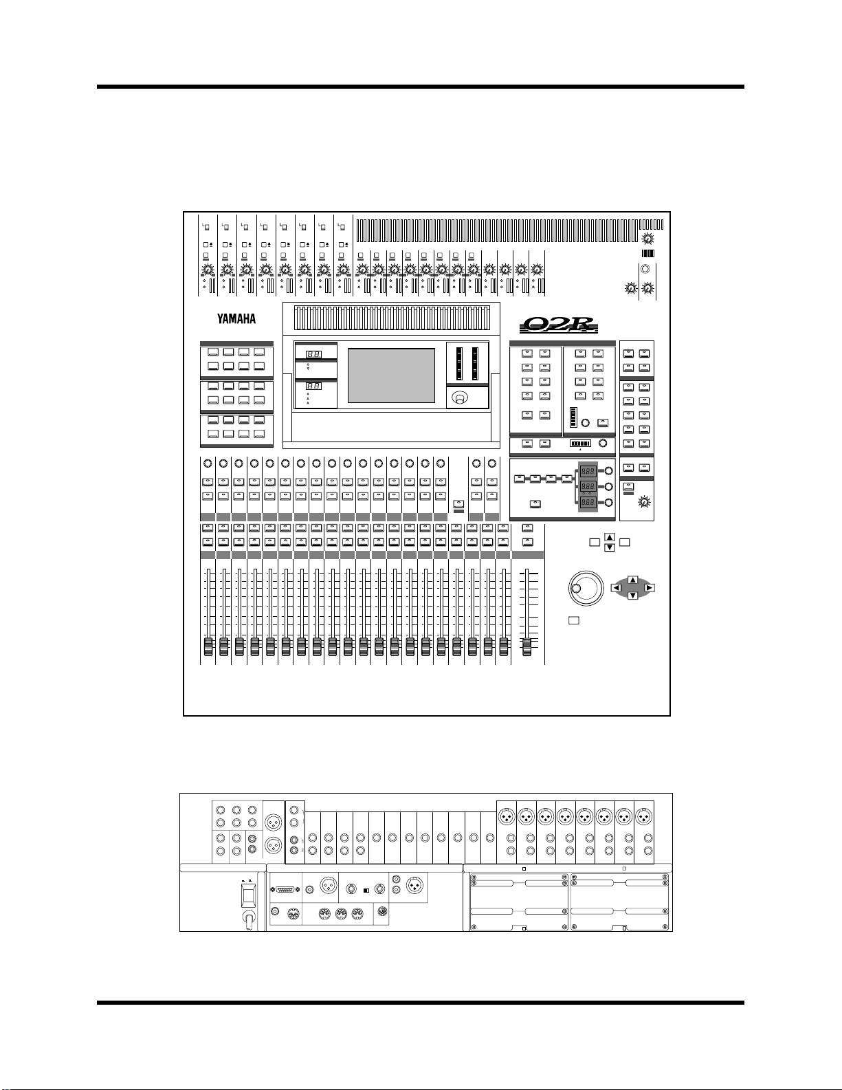
Top and Rear Panels
+48V
+48V
+48V
+48V
+48V
+48V
+48V
+4 -40
-16 -60
PEAK
SIGNAL
SEL
ON
TAPE
7
SEL
ON
5
0
5
ON
OFF
20dB
GAIN
6
SCENE MEMORY
FADER STATUS
1234
5678
SELECTED CHANNEL
MIC/LINE
TAPE/RTN
OUTPUT
7
+48V
ON
ON
OFF
OFF
A
A
A
B
B
B
20dB
20dB
20dB
20dB
20dB
20dB
20dB
20dB
PEAK
SIGNAL
+4 -40
-16 -60
20dB
+4 -40
+4 -40
+4 -40
+4 -40
+4 -40
GAIN
GAIN
GAIN
-16 -60
-16 -60
PEAK
PEAK
SIGNAL
SIGNAL
7
8
9
-16 -60
PEAK
SIGNAL
+4 -40
GAIN
GAIN
GAIN
GAIN
-16 -60
-16 -60
-16 -60
PEAK
PEAK
PEAK
SIGNAL
SIGNAL
SIGNAL
10
11
13
12
+4 -40
-16 -60
PEAK
SIGNAL
20dB
+4 -40
+4 -40
+4 -40
+4 -40
+4 -40
GAIN
GAIN
GAIN
GAIN
-16 -60
-16 -60
PEAK
PEAK
PEAK
SIGNAL
SIGNAL
14
SIGNAL
15
16
17/18
+4 -40
GAIN
GAIN
GAIN
PEAK
PEAK
PEAK
SIGNAL
SIGNAL
SIGNAL
19/20
21/22
23/24
010
STUDIO
LEVEL
010
T/B LEVEL
010
PHONES
LEVEL
DIGITAL RECORDING CONSOLE
10
15
20
30
40
50
60
70
∞
0
5
STEREO
1
3
5
7
ROUTING
EQ ON
SEL
ON
SELECTED CHANNEL
2
4
6
8
DIRECTST
RL/MONO
PAN
EQUALIZER
AUX 2
AUX 1
AUX 3
AUX 5
AUX 7
EFF1
SEND LEVEL
L
ODD
HIGH/LPFH-MIDL-MIDLOW/HPF
AUX
EVEN
Hz kHz
AUX 4
AUX 6
AUX 8
EFF2
R
dB
STORE
ON
Q
F
G
SCENE MEMORY
C-R
AUX 5STAUX 6
2TR-D1 2TR-A1
2TR-D2 2TR-A2
2TR-D3 ST
AUX 5
MONO
CONTROL ROOM
SLATE T/B
TALKBACK
SOLO
RECALL
STUDIO
AUX 6
DIM
010
C-R
LEVEL
CURSOR
ENTER
CLIP
-2
-4
-6
-12
INPUT
AUX
SEL
SEL
SEL
SEL
SEL
SEL
SEL
SEL
ON
ON
ON
ON
ON
ON
ON
ON
TAPE
TAPE
9
8
SEL
SEL
ON
ON
10
10
5
5
0
0
5
5
10
10
15
15
20
20
30
30
40
40
50
50
∞
∞
8
9
TAPE
TAPE
TAPE
12
11
10
SEL
SEL
SEL
ON
ON
ON
10
10
10
5
5
5
0
0
0
5
5
5
10
10
10
15
15
15
20
20
20
30
30
30
40
40
40
50
50
50
∞
∞
∞
10
11
12
TAPE
TAPE
TAPE
15
14
13
SEL
SEL
SEL
ON
ON
ON
10
10
10
5
5
5
0
0
0
5
5
5
10
10
10
15
15
15
20
20
20
30
30
30
40
40
40
50
50
50
∞
∞
∞
13
14
15
-15
-24
-35
-48
-60
-72
L STEREO R
CONTRAST
SEL
SEL
SEL
ON
ON
ON
TAPE
16
SEL
ON
10
5
0
5
10
15
20
30
40
50
∞
16
EFF2
EFF1
RTN
RTN
FLIP
SELONSELONSELONSEL
ON
10
10
10
5
0
5
10
15
20
30
40
50
∞
17/18
10
5
5
5
0
0
0
5
5
5
10
10
10
15
15
15
20
20
20
30
30
30
40
40
40
50
50
50
∞
∞
∞
19/20
21/22
23/24
ON
ON
OFF
OFF
A
A
B
B
20dB
20dB
+4 -40
+4 -40
GAIN
GAIN
-16 -60
-16 -60
PEAK
PEAK
SIGNAL
SIGNAL
1
2
DISPLAY ACCESS
DIGITAL
SCENE
I/O
MEMORY
MIDI
AUTOMIX GROUP
CONFIGURATION
Ø/ATT DELAY
VIEW
METER
MIXING
AUX 1 AUX 2 AUX 3 AUX 4
AUX 5 AUX 6
AUX
SEL
SEL
ON
ON
TAPE
TAPE
2
1
SEL
SEL
ON
ON
10
10
10
5
5
0
0
5
5
10
10
10
15
15
15
20
20
20
30
30
30
40
40
40
50
50
50
∞
∞
∞
1
2
+4 -40
-16 -60
PEAK
SIGNAL
SETUP
PAN ROUTING
AUX 7
EFF1
SEL
ON
TAPE
3
SEL
ON
5
0
5
3
ON
ON
ON
OFF
OFF
OFF
A
A
A
B
B
SIGNAL
20dB
+4 -40
-16 -60
PEAK
B
20dB
+4 -40
GAIN
GAIN
-16 -60
PEAK
SIGNAL
4
5
20dB
GAIN
3
UTILITY
PAIR
EQ
DYNAMICS
AUX 8
EFF2
SEL
SEL
SEL
ON
ON
ON
TAPE
TAPE
TAPE
6
5
4
SEL
SEL
SEL
ON
ON
ON
10
10
10
5
0
5
10
15
20
30
40
50
∞
10
5
5
0
0
5
5
10
10
10
15
15
15
20
20
20
30
30
30
40
40
40
50
50
50
∞
∞
∞
4
5
6
5
6
AUX SEND
LRL
C- R
STUDIO
MONITOR
MONITOR
OUT
+4dB +4dB
OUT
02R Getting Started Guide
1
3
4
2
+4dB
L
R
R
-10dBV
STEREO OUT ANALOG
POWER
ON/ OFF
12
TIME
+4dB
SMPTE
L
R
METER
CODE INPUT
+4dB
-10dBV
2TR IN
ANALOG
MTC
L
1
R
INPUT INPUT INPUT INPUT
23
L
2
R
2224
COAXIAL
AES/EBU
STEREO OUT
DIGITAL
THRU OUT
MIDI
1718192021
75Ω
ON OFF
WORD CLOCK
IN
INOUT
TO HOST
COAXIAL
2TR IN DIGITAL
INPUT AINPUT A
INPUT A
INPUT A INPUT A INPUT A
INPUT A
INPUT
INPUT
INPUT
B
B
B
INSERT
INSERT
INPUTINPUTINPUTINPUTINPUTINPUTINPUTINPUTINPUTINPUTINPUTINPUT
AES/EBU
1
2
3
INSERT
I/O
I/O
I/O
8910111213141516
SLOT 4
INPUT
INSERT
I/O
INPUT
INPUT
B
B
INSERT
INSERT
I/O
I/O
SLOT 2
INPUT A
INPUT
INPUT
B
B
B
INSERT
INSERT
I/O
I/O
1234567
0dB0dB0dB0dB0dB0dB0dB0dB
SLOT 3
SLOT 1
Page 14

Introduction to the 02R
Features
Sonic Specifications
• Linear 20-bit 64-times oversampling A/D convertors
• Linear 20-bit 8-times oversampling D/A convertors
• 105 dB dynamic range (typical)
• 32-bit precision internal processing with a dynamic range of over
190 dB using Yamaha’s 32-bit proprietary audio DSP
General Features
• 40 input channel mixer, with full dynamic processing and 4-band
parametric equalization
• Dynamic automix—all referenced to timecode
• 96 internal scene memories for storing all digital mixer settings
• 4-band Parametric EQ with sweepable center-frequency from 20 Hz to
20kHz and adjustable bandwidth (Q)
5
• Extensive EQ library
• Comprehensive dynamics processors on each input channel, tape
return, and buss and stereo output:
• Compressor
• Expander
• Gate/Ducking
• Soft and Hard Compander
• Dynamics library
• Fully programmable channel settings: phase and attenuation, delay,
pan, routing, meters, EQ, and dynamics
• Channel library
• Two internal stereo effects using proprietary processor chip
• Effects library
• 8 output busses, 8 auxiliary send busses, and main stereo mix buss
• 24 balanced analog inputs (8 channels with either XLR-type or phone
connectors)
• Continuously variable gain control
• 20 dB input pad
• 8 XLR-type inputs with 48V phantom power for condenser
microphones
• 8 analog insert input/output connections
• 2 analog 2TR IN inputs
02R Getting Started Guide
Page 15

6
Introduction to the 02R
• 2 analog stereo outputs
• 6 analog auxiliary send outputs
• Stereo studio and control room outputs
• 3 digital 2TR IN inputs
• 2 digital stereo outputs
• Industry standard AES/EBU or IEC958 Part2 (Consumer) digital
• 100 mm motorized faders
• Fader and mute groups for single fader or button control over several
• Adjacent channel pair function for stereo operation on inputs, tape
• Dedicated buttons and controls of the Selected Channel module
• Large 320
• RISC technology CPU
• SMPTE and MTC synchronization plus full MIDI implementation
inputs and outputs
faders or channel ON buttons
returns, and auxiliary channels
×
240 pixel, FL-backlit, user-friendly graphical display
Options
• Digital I/O cards:
• ADAT (CD8-AT)
• TASCAM (CD8-TDII)
• Yamaha (CD8-Y)
• AES/EBU double slot card (CD8-AE)
• AES/EBU single slot card (CD8-AE-S)
• Cascade Kit (CD8-CS)
• Analog I/O cards
• Analog I/O double slot card (CD8-AD)
• Analog input single slot card (CD8-AD-S)
• Automix 1 MB memory expansion (ME4M)
• Meter bridge (MB02)
• Wooden side panels (W02SP)
02R Getting Started Guide
Page 16

Introduction to the 02R
Key Features
This section looks at some of the key features of the 02R, what they mean to
you, and some hints about how you can use them.
Dynamic Automix
One of the most demanding jobs of the recording engineer is taking all the
raw material produced during a multitrack recording session and mixing it
all together into an artistically satisfying master recording. The ability to
setup portions of the mix and then have them playback automatically as
you work on other portions is probably the most important feature of the
02R.
It has an on-board automix system that memorizes fader positions,
switches individual channels on or off, adjusts the EQ or pan positions, and
changes the auxiliary sends—all referenced to timecode. It can also record
and execute scene memory changes, also referenced to timecode. This
allows you to perform an entire mixing session, and then edit individual
channel settings until you have achieved the perfect mix.
7
The 02R allows you to record a mixdown in real-time and then edit the
results, either in real-time or by using one of the event editors. You can
select single parameters of the mixer to edit—for example, just enable the
faders for one pass as you create your mixdown.
Scene Memories
The 02R has 96 internal scene memories each of which is a snapshot of all
the digital settings of the mixer (a mix scene). Each can be named for easy
identification. They can be stored and later recalled instantly.
If you work on several projects at one time, you can store the current mixer
settings in a scene memory so when you return to that project, you can start
immediately from where you left off. When you are working on a
mixdown, the ability to recall mixer scenes can speed the process and
allows for accurate repetition of the various parts of the mix. When you use
the 02R for sound reinforcement applications, the ability to recall mix
scenes can make light work of night-after-night sound checks.
Storing the mixer settings to a scene memory is a simple matter of pressing
the [STORE] button and confirming the request.
Note: You can customize your 02R to perform the storage operation without
confirmation. See “Preferences” on page 198 of the User’s Guide for more details.
02R Getting Started Guide
Page 17

8
Introduction to the 02R
Recalling the scene is even easier—just press the [RECALL] button. You
should be careful that your scene memories flow into each other smoothly.
The instant recall means that you can have very abrupt level changes or the
unexpected intrusion of a very loud channel.
Note: The 02R allows you to have programmable fades between scene memories.
The only thing you need to watch is the sudden sound of a channel being switched
on. Even then, if the original channel level was set to –
problems. See “Fade Time” on page 136 of the User’s Guide.
dB, you should have no
∞
Large Graphical Display
The heart of the 02R user interface is the large graphical display located in
the center of the console. Using the Display Access controls, you can gain
immediate access to the features of the mixer—clearly displayed on the 320
×
240 pixel, FL-backlit, user-friendly graphical display. Virtual control
modules are shown on the display, allowing you to adjust almost any
digital parameter anywhere in the system.
As well as displaying parameter values numerically, faders, rotary controls,
and push buttons are represented graphically, so you can actually see
button status, pan positions, and fader levels.
In addition the EQ curves are displayed graphically as are the dynamics
processor parameters.
User Interface
The 02R user interface is powerful but very intuitive. There are two main
methods of working with the 02R:
• Use the DISPLAY ACCESS controls to modify one parameter at a time
across the entire recording console.
• Use the SELECTED CHANNEL controls to modify all of the
parameters of the currently selected channel.
The DISPLAY ACCESS controls consist of a block of 24 function buttons
divided into three groups—CONFIGURATION, MIXING, and AUX—plus
the large backlit graphical display, four cursor buttons, a detented encoder
wheel, and the [ENTER] button. There is also a related block of four SCENE
MEMORY buttons—to increment, decrement, store, and recall the scene
memories.
The SELECTED CHANNEL controls consist of four main blocks of
controls—each block was designed to be as familiar as the equivalent
controls on a regular analog mixer, but with the power of digital precision
and instant recall. The ROUTING block selects the bus onto which to route
the current channel signal. The AUX block selects the auxiliary buss to send
the channel signal to and sets the send level. The PAN block sets the pan
position of the channel signal. The EQ block sets the EQ curve for the
02R Getting Started Guide
Page 18

Introduction to the 02R
current channel. You can customize your 02R to automatically select the
corresponding display pages when you adjust a control in these blocks.
Motorized Faders
In addition to the DISPLAY ACCESS and SELECTED CHANNEL controls,
each input channel and the stereo master channel utilizes a 100 mm
motorized fader. When a scene memory is recalled, the faders position
themselves automatically to the levels stored. Fader movements are
replayed automatically in synchronization with timecode automix during
playback.
The faders allow you to quickly and accurately set the levels for the
selected channels. By pressing the [FLIP] button, you can transfer fader
control over your tape returns as well. Faders can be grouped into one of
four fader groups for control of multiple faders from a single control.
(There are also four mute groups which allow you to toggle a group of
channels on or off.) You can also control two adjacent channels in stereo
with the pair operation using only one fader.
9
Internal Stereo Effects
The 02R features eight aux sends, two of which are routed to the internal
multi-effects stereo processors: Effect 1 and Effect 2. Using the power of
Yamaha’s proprietary effects processor chip, the 02R has a startling range of
special effects available to apply to your mix. Shimmering reverbs, clean
and precise delays, flanging and chorus, and a myriad of other effects are
available built right into this mixer. The effects are processed entirely
within the digital domain, ensuring the signal quality is the finest that a
digital system can provide.
External effects processors can be patched into the system using the 02R’s
analog AUX send outputs, which feature 18-bit linear, 8-times
oversampling D/A converters.
Effects can be applied to input channels or the tape return channels, and the
auxiliary sends can be configured pre-fader or post-fader. There are 40
preset effects programs and 88 user effects programs for you to store your
own settings.
Dynamics Processors
Dynamics processors are generally used to correct or control signal levels.
However, you can also use them creatively to shape the volume envelope
of a sound. The 02R features comprehensive dynamics processors for all
the input, return, bus, and stereo output channels—a total of 50 processors.
These processors allow you to compress, expand, limit, gate, or duck the
signals passing through the mixer, giving you unparalleled sonic quality
and flexibility.
Similar to the internal stereo effects, the dynamics processors are patched
directly into the signal path while the audio data remains in the digital
02R Getting Started Guide
Page 19

10
Introduction to the 02R
domain. The dynamics program settings are stored in the dynamics library.
There are 40 preset programs for you to recall and 88 user programs for you
to store your own dynamics programs
Parametric EQ with Library
The 02R contains a high-performance four-band, fully parametric EQ. Each
input channel, tape and effect return, and the stereo output channel
features an EQ. You can tailor the EQ curve with a high degree of precision,
covering the entire dynamic spectrum from 21 Hz to 20.1 kHz. Select the
center-frequency (F) and adjust the bandwidth (Q) and the gain (G) until
you have achieved the perfect sound.
EQ settings can be stored and recalled using scene memories, and can be
adjusted in real-time with the dynamic automix system. The 02R also has
an extensive EQ library which allows you to store frequently used EQ
settings for instant recall. An EQ program stored in the EQ library is a good
starting point and reference when making adjustments to the EQ.
Digital Benefits
You’re probably already familiar with the many benefits of digital audio,
but what exactly are the benefits for digital audio mixing?
An audio mixer has the job of combining audio signals from various
sources, at differing levels and impedances, usually into a stereo signal. It
must do this without introducing any new distortions and noise. Most
analog mixers do a pretty good job, but even with the best designs,
nonlinear effects caused by circuit components are unavoidable.
In the digital realm, audio mixing consists of adding and multiplying the
binary numbers that represent audio signals. The 02R uses a 32-bit DSP
(Digital Signal Processor) chip for these calculations, ensuring a very high
degree of precision. Once past the analog-to-digital conversion, audio
signals are essentially immune from standard signal degradation. With the
02R, noise, distortion, and crosstalk are virtually eliminated. You’ll hear a
new clarity in your mixes.
Once in the digital realm, there’s little point converting back to analog. The
02R features stereo digital outputs for direct mixdown to DAT and other
digital recorders. It uses the industry standards AES/EBU or IEC958 Part 2
(Consumer) for its digital inputs and outputs. With one of the optional
digital I/O cards installed in your 02R, you can record direct-to-digital to
your modular digital multitrack recorder.
02R Getting Started Guide
Page 20

Introduction to the 02R
11
02R Sonic Performance
The 02R uses linear 20-bit 64-times oversampling analog-to-digital
converters to provide a typical dynamic range of 105 dB. This means that
an audio program’s dynamic range, from low to high levels, is processed
intact. The 02R samples audio at 44.1 kHz or 48 kHz. It provides a full
spectrum frequency response from 20 Hz to 20 kHz, +1, –3 dB.
For digital-to-analog conversion, the 02R features 20-bit 8-times
oversampling for its main stereo outputs, including the control room
monitor outputs, and 18-bit 8-times oversampling for the studio and aux
send outputs. Oversampling and bitstream techniques effectively increase
the internal sampling rate, so side effects caused by steep low-pass filters,
which are used to filter out undesirable sampling frequency components
during conversion, are virtually eliminated. Consequently, audio signal
integrity is maintained from input through to output.
02R Getting Started Guide
Page 21

12
Introduction to the 02R
02R Getting Started Guide
Page 22

2
Getting Started
13
Getting Started
In this chapter...
Basic Assumptions. . . . . . . . . . . . . . . . . . . . . . . . . . . . . . . . . . . . . . . . . . . . . . 14
Making the Connections. . . . . . . . . . . . . . . . . . . . . . . . . . . . . . . . . . . . . . . . . 14
Basic Setup . . . . . . . . . . . . . . . . . . . . . . . . . . . . . . . . . . . . . . . . . . . . . . . . . . . . 15
Power ON/OFF . . . . . . . . . . . . . . . . . . . . . . . . . . . . . . . . . . . . . . . . . . . . . . . . 16
2
Setting the Synchronization . . . . . . . . . . . . . . . . . . . . . . . . . . . . . . . . . . . . . . 16
Recall Scene Memory 0 . . . . . . . . . . . . . . . . . . . . . . . . . . . . . . . . . . . . . . . . . . 17
02R Getting Started Guide
Page 23

14 Getting Started
WARNING! Bef
WARNING! The 02R
Basic Assumptions
The 02R was designed to be the perfect digital mixing console for a studio
using the current generation of modular digital multitrack tape and disk
recorders. Although the 02R can also be used as a sound-reinforcement
mixer, the typical user will own a project recording or post-production
studio with some form of multitrack recorder. Therefore, your 02R will
probably be equipped with one or more of the optional input/output
cards. For the purposes of these tutorials, it does not matter if you are
working with an analog or digital multitrack.
What You Will Need
To perform the following tutorials, you will need:
• The 02R.
• A sound source: CD player, drum machine, synthesizer/sequencer
with demo song.
• Amplifiers and speakers, or headphones.
ore
making any connections,
make sure that all your
equipment is turned OFF.
• A multitrack recorder and a stereo master recorder.
• Audio connecting cables.
Making the Connections
1. Connect your sound source to input channel 1.
If you are using a stereo sound source, connect it to input channel 2 as well.
A stereo source is not essential, and for most of the tutorials it will probably
be easier to work with just one channel. If your sound source has XLR-type
connectors, connect it to the XLR-type connectors on the 02R. Otherwise,
use the phone jacks and select INPUT B with the [A/B] switch.
2. Connect the C-R MONITOR OUT connectors to the inputs on your
power amplifier.
If you are using headphones, connect them to the PHONES jack.
3. Connect your multitrack recorder to the appropriate optional
input/output card.
should be connected only to
an AC receptacle of the
voltage type marked on its
rear panel.
02R Getting Started Guide
You can also connect your stereo master recorder to either the digital or
analog STEREO OUT connectors.
4. Plug the 02R into a suitable AC receptacle.
Page 24
Getting Started 15
Basic Setup
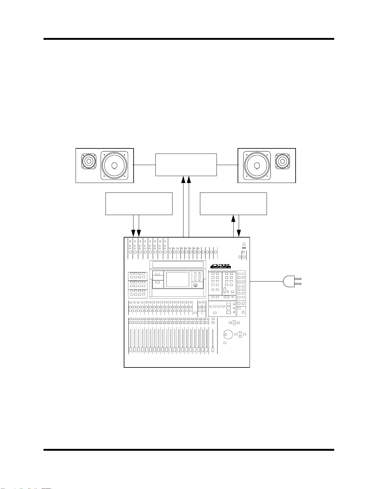
The following illustration shows how to set up a minimal system that will
allow you to perform the following tutorials.
Amplifier
Sound Source Multitrack recorder
02R Getting Started Guide
Page 25

16 Getting Started
Power ON/OFF
This section explains how to power the 02R on and off.
Power ON
It is always important to observe the correct order for powering up
equipment in a studio. Always start with the multitrack and mastering
recorders and the signal processors, then the 02R, and finally the
monitoring amplifiers and other downstream gear.
POWER
ON/ OFF
1. Turn ON the power to the 02R by pressing the POWER switch on
the rear panel.
The 02R start-up screen appears for a few seconds, the faders return to their
previous positions, then the page that was used when the 02R was last
powered off appears.
Power OFF
It is always important to observe the correct order for powering off
equipment in a studio. Always start with the monitoring amplifiers and
other downstream gear, then the 02R, and finally the multitrack and
mastering recorders and the signal processors.
1. Turn OFF the power to the 02R by pressing the POWER switch on
the rear panel.
All mix settings, mix scenes, and other data are stored when the 02R is
powered off.
Setting the Synchronization
02R Getting Started Guide
Before you use the 02R with a modular digital multitrack recorder or DAT
master recorder, be sure to correctly set the synchronization. The 02R must
be slaved to an external wordclock in order to process the input digital
signals without drop-out or distortion. Refer to the section “Word Clock
Select” on page 188 of the User’s Guide.
Look in the chapter “Installing Options” on page 217 of the User’s Guide.
There is a section for each of the optional digital I/O cards that the 02R
supports. Refer to the appropriate section for the card installed in your 02R.
Page 26

Getting Started 17
Recall Scene Memory 0
Before you start the tutorials, you should set the 02R to its initial mixer
settings.
1. Use the SCENE MEMORY increment or decrement buttons to
select scene memory 0 “0 Initial Data”.
2. Press the [RECALL] button.
STORE
SCENE MEMORY
RECALL
This is a read-only scene memory that contains the default settings for the
system. The 02R will be reset to its initial settings.
Note: It is best to start at the beginning of each tutorial and work your way
through, taking breaks as required. If you deviate too far from the tutorial, or jump
into a tutorial halfway through, you may find that subsequent tutorial steps do not
work as expected. Also note that the tutorials do not explain all 02R functions, nor
do they serve as a substitute for the User’s Guide explanations. For full details on
all 02R functions, refer to the User’s Guide.
02R Getting Started Guide
Page 27

18 Getting Started
02R Getting Started Guide
Page 28

3
Introductory Recording Tutorial 19
Introductory Recording Tutorial
In this chapter...
Setting the Input Level . . . . . . . . . . . . . . . . . . . . . . . . . . . . . . . . . . . . . . . . . . 20
Applying EQ . . . . . . . . . . . . . . . . . . . . . . . . . . . . . . . . . . . . . . . . . . . . . . . . . . 24
Using the EQ Library . . . . . . . . . . . . . . . . . . . . . . . . . . . . . . . . . . . . . . . . . . . 30
Routing . . . . . . . . . . . . . . . . . . . . . . . . . . . . . . . . . . . . . . . . . . . . . . . . . . . . . . . 35
3
Panning . . . . . . . . . . . . . . . . . . . . . . . . . . . . . . . . . . . . . . . . . . . . . . . . . . . . . . . 38
02R Getting Started Guide
Page 29
20 Introductory Recording Tutorial
Setting the Input Level
Assuming that the 02R is powered ON and your music source is playing,
the very first thing you need to do is set up a basic control room monitor
mix. When you recall Scene Memory 0 “0 Initial Data”, all the channel
faders are set to the 0 dB mark.
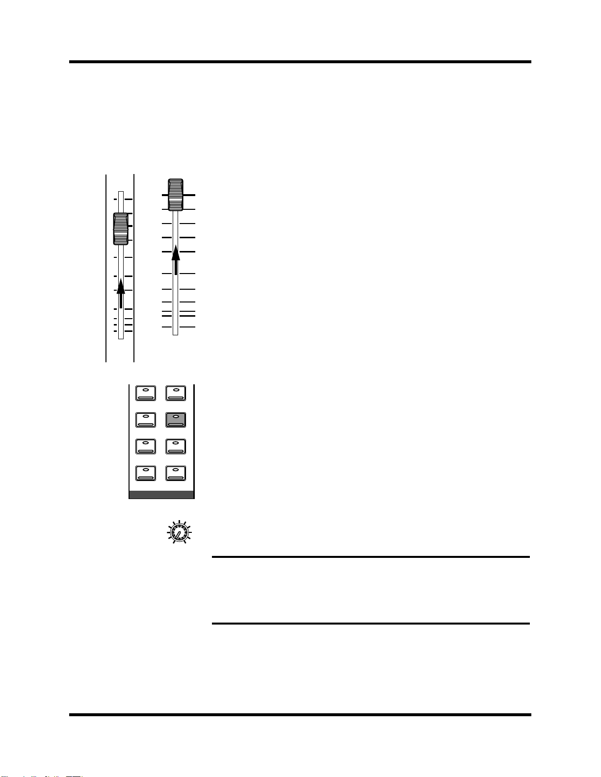
Setting Fader Levels
10
5
0
5
10
15
20
30
40
50
∞
1
0
5
10
15
20
30
40
50
60
70
∞
STEREO
If the faders are not set to 0 dB, you should perform the following steps to
optimize the input signal level for the best performance:
1. Set the fader for MIC/LINE 1 to the 0 dB mark.
The 0 dB fader position is a good place to start when setting fader levels. It
is a good setting with regard to signal level and noise performance and it
leaves room for you to raise the level later, if necessary.
2. Set the STEREO fader to the 0 dB mark.
The stereo output meters are indicating the stereo output level. The stereo
mix signal is now being output to the digital and analog STEREO OUT
connectors.
2TR-D2 2TR-A2
2TR-D3 ST
AUX 5
MONO
CONTROL ROOM
AUX 6
DIM
010
C-R
LEVEL
Selecting a Monitor Source
Before you can hear anything through your monitor amplifier and
speakers, you have to select a Control Room source:
1. Press the [ST] button of the CONTROL ROOM buttons group.
This selects the stereo bus for monitoring in the control room.
2. Adjust the volume with the C-R LEVEL control.
You should be able to hear the sound source through your monitor
speakers. If you are using stereo headphones, you will need to adjust the
PHONES LEVEL control to set a comfortable listening level.
Note: Be very careful with the level settings, especially if you are using stereo
headphones. When you are adjusting a unit as complex as the 02R, it is possible for
you to inadvertently switch on a very loud signal source. Damaged loudspeakers or
amplifiers can be very expensive. Damage to your hearing can be much worse. Your
ears are for life!
02R Getting Started Guide
Page 30

Introductory Recording Tutorial 21
Setting the GAIN
1. Use the [METER] button to locate the METER 1/3 page.
METER
20dB
The MIC/LINE 1 signal is metered.
2. If the sound is distorted, the PEAK indicator is illuminated, or the
level is going up to CLIP, press the 20 dB (pad) switch to attenuate
the input signal for MIC/LINE 1.
You usually need to pad (attenuate) the input signal when you connect a
line level device, such as a synthesizer or an effects unit to the channel. If
you connect a microphone, you should not need to pad the signal.
+4 -40
GAIN
-16 -60
If you want to use a high impedance device, such as a guitar or bass guitar,
you should insert a direct box or effects processor between the guitar and
the 02R—or you should mike the guitar amplifier.
Note: The stereo input channels (LINE 17 through 24) accept line level signals
only.
3. Use the GAIN control for MIC/LINE 1 to optimize the signal level.
Ideally the level should be set relatively high to obtain the best
signal-to-noise performance. It is acceptable for the PEAK indicator to
occasionally illuminate but the signal levels should not reach CLIP. If the
PEAK indicator illuminates constantly, the signal is overloading the input
preamplifier and you may be able to hear analog clipping distortion. When
CLIP is reached, you will experience digital clipping distortion, which is
usually very unpleasant sounding.
02R Getting Started Guide
Page 31
22 Introductory Recording Tutorial
Back off the GAIN control a little until the PEAK indicator illuminates very
occasionally. The GAIN control should be set with some care. If it is set too
low, the signal-to-noise performance will suffer, and if it is set too high,
signal clipping and distortion may occur.
∅/ATT Display Function
If a lot of EQ boost is applied, the signal level may reach CLIP on the
METER page but the PEAK LED may not light up. Instead of lowering the
GAIN control, which would reduce A/D converter efficiency, you can use
the Attenuator function to attenuate the level.
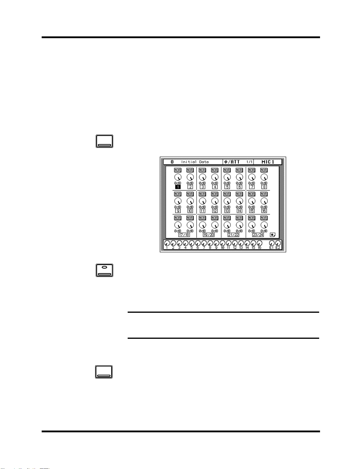
1. Press the [∅/ATT] button.
Ø/ATT
SEL
The ∅/ATT 1/1 page shown below appears.
2. Press the [SEL] button for MIC/LINE 1.
3. Use the encoder wheel to attenuate the signal.
On the ∅/ATT page you can attenuate signals and reverse the phase, all in
the digital domain.
Note: You should rarely find it necessary to use the ∅/ATT function on an input
signal after the gain level has been correctly set, but you may need to attenuate
after you apply EQ, effects, or dynamics to the signal.
METER
02R Getting Started Guide
Peak Hold
1. Use the [METER] button to locate the METER 1/3 page.
2. You may find the Peak Hold function useful at this point. To turn it
on, use the CURSOR buttons to select the PEAK HOLD icon and
press [ENTER]. When the Peak Hold function is on, its icon is
highlighted.
Page 32

Introductory Recording Tutorial 23
The peak level is indicated by an empty square box. Peak Hold is very
useful for level checking before recording. You can leave a mix to play
through unattended while Peak Hold watches out for signal peaks. If any
levels reach CLIP, back off the relevant GAIN control or use the ∅/ATT
display function to attenuate the signal and run through the mix again.
Note: The Peak Hold function also works on the stereo output meters and
controls the optional meter bridge (MB02).
3. To clear the Peak Hold levels, select the PEAK HOLD icon with the
CURSOR buttons and press [ENTER].
When you clear the Peak Hold levels, it also clears the peaks from the
stereo output meters.
Typically, you will be using more than just one input channel, so you will
need to set the input signal level for each channel individually. Since it is
relatively easy to set them at this point, take time and care. If you have to
adjust them later in the mixing process, you may need to adjust the faders,
auxiliary sends, and other levels, as well.
SCENE MEMORY
Edit Indicator
ON
Channel ON/OFF
The channel [ON] buttons are used to turn channels ON or OFF. This
function is sometimes called MUTE. When you recall Scene Memory 0 “0
Initial Data”, all the channels are turned ON.
1. Press the channel [ON] button for MIC/LINE 1.
The sound is cut and the LED inset in the [ON] button switches off.
Note: Even though you can no longer hear the sound source, the meter for
MIC/LINE 1 continues to be displayed. This is because the meter signal is sourced
before the [ON] button.
2. Press the [ON] button again to turn the channel back ON.
The LED inset in the [ON] button illuminates again and you will be able to
hear the sound source again.
SCENE MEMORY LED
The 2-digit (7-segment) LED shows the currently selected scene memory. It
also contains the Edit Indicator, which will start flashing when you adjust
the first digital parameter of the current scene memory. See “Scene
Memories” on page 62 of the Getting Started Guide.
02R Getting Started Guide
Page 33

24 Introductory Recording Tutorial
Applying EQ
The next step is to apply EQ to MIC/LINE 1.
Each 02R channel features a four-band fully parametric EQ, with variable
bandwidth (Q), frequency (F), and gain (G). The power of the 02R user
interface means that there are two ways of adjusting the EQ for
MIC/LINE 1.
One method is to use the EQ 1/2 page.
The more convenient method is to use the buttons and controls of the
EQUALIZER block of the SELECTED CHANNEL controls.
Q
SEL
HIGH/LPFH-MIDL-MIDLOW/HPF
Hz kHz
EQ ON
EQUALIZER
F
G
dB
Note: You can customize your 02R so that when you adjust a control of the EQ
block of the SELECTED CHANNEL controls, the EQ 1/2 page automatically
appears. See “Preferences” on page 198 of the User’s Guide for more information.
The default setting is to automatically display the EQ page.
The rest of this tutorial describes the operation of the EQ 1/2 page.
Turning the EQ ON/OFF
1. Press the [SEL] button for MIC/LINE 1.
When you press the [SEL] button for a channel, the LED and numeric
indicators of the SELECTED CHANNEL controls change to reflect the
status of the channel you selected.
EQ
02R Getting Started Guide
2. Press the [EQ] button.
Page 34

Introductory Recording Tutorial 25
The EQ 1/2 page appears, showing the EQ curve and settings for
MIC/LINE 1.
3. Use the CURSOR buttons to select the EQ ON icon.
If the EQ is ON, the icon will be highlighted. The LED inset in the [EQ ON]
button of the SELECTED CHANNEL—EQUALIZER block controls will
also be illuminated.
4. To turn the EQ either on or off, press the [ENTER] button or the
[EQ ON] button.
The ON icon will change to OFF. The LED inset in the [EQ ON] button will
no longer be illuminated.
Turn the EQ on for the remainder of this tutorial.
Setting the Gain
1. Select the gain (G) icon for the LOW band using the CURSOR
buttons.
Alternatively, press the [LOW/HPF] button of the SELECTED
CHANNEL—EQUALIZER controls.
2. Rotate the encoder wheel clockwise to boost the gain.
Alternatively, you could use the EQUALIZER G control.
02R Getting Started Guide
Page 35

26 Introductory Recording Tutorial
The gain increases in 0.5 dB steps and the EQ curve on the EQ page
changes to reflect this.
3. Rotate the encoder wheel counterclockwise to reduce the gain.
The gain decreases in 0.5 dB steps.
Alternatively, you could use the EQUALIZER G control.
4. Use the CURSOR buttons to select the gain (G) icon for the L-MID
band and adjust its level with the encoder wheel. Select the
other bands as well.
You can also select the EQ bands using the [LOW/HPF], [L-MID],
[H-MID], and [HIGH/LPF] buttons of the SELECTED
CHANNEL—EQUALIZER controls.
Note: Applying a lot of EQ boost may increase the signal level sufficiently to
cause distortion. If this does occur, reduce the amount of EQ boost or adjust the
attenuation level to compensate (the ATT icon). You can switch back to the
METER 1/3 page and select POST EQ to monitor the signal levels.
Note: You can reset the gain of each band to 0.0 dB by double-clicking the
corresponding [LOW/HPF], [L-MID], [H-MID], or [HIGH/LPF] buttons of the
SELECTED CHANNEL—EQUALIZER controls.
02R Getting Started Guide
Page 36

Introductory Recording Tutorial 27
Setting the Frequency
1. Select the frequency (F) icon for the LOW band using the CURSOR
buttons.
2. Use the encoder wheel to sweep through the frequency range.
Alternatively, you could use the EQUALIZER F control.
All four bands of the 02R parametric EQ cover virtually the entire audio
spectrum, from 21 Hz to 20.1 kHz. Although they are labelled LOW,
L-MID, H-MID, and HIGH, the frequency of the bands can actually be in
any order.
Note: If your 02R is busy processing some complex data, it may take a little time
to update the EQ curve. However, the internal EQ circuits reflect your
adjustments immediately.
Note: As well as the frequency value in Hz displayed under the icon and on the
numeric LED in the SELECTED CHANNEL—EQUALIZER controls, the dotted
vertical line on the EQ graph indicates the current frequency position.
3. Use the CURSOR buttons to select the frequency (F) icon for the
L-MID band and adjust its position with the encoder wheel. Select
the other bands and adjust their frequency.
You can also select the EQ bands using the [LOW/HPF], [L-MID],
[H-MID], and [HIGH/LPF] buttons of the SELECTED
CHANNEL—EQUALIZER controls. Adjust the EQUALIZER F control for
each band.
02R Getting Started Guide
Page 37

28 Introductory Recording Tutorial
Setting the Bandwidth
The L-MID and H-MID bands are peaking type EQs. The LOW and HIGH
bands are initially configured as shelving type EQs, however, they can also
be configured as peaking type EQs. The LOW band can also be configured
as a HPF (high-pass filter) and the HIGH band as a LPF (low-pass filter).
1. Select the bandwidth (Q) icon for the LOW band using the
CURSOR buttons.
2. Use the encoder wheel to sweep through the bandwidth.
Alternatively, you could use the EQUALIZER Q control.
The LOW band changes from low-shelving to peaking to high-pass filter as
you continue to rotate the encoder wheel.
3. As you rotate the encoder wheel counterclockwise, it effectively
increases the Q—narrowing the bandwidth, as shown on the EQ
graph.
02R Getting Started Guide
A narrow curve is useful for boosting or cutting specific frequencies.
4. Use the CURSOR buttons to select the bandwidth (Q) icon for the
L-MID band and adjust its position with the encoder wheel. Select
and adjust the bandwidth of the other bands.
You can also select the different bands using the [LOW/HPF], [L-MID],
[H-MID], and [HIGH/LPF] buttons of the SELECTED
CHANNEL—EQUALIZER controls. Adjust the EQUALIZER Q control for
each band.
The HIGH band changes from high-shelving to peaking to low-pass filter
as you adjust its value.
Page 38

Introductory Recording Tutorial 29
Resetting the EQ
1. Press and hold the [LOW/HPF] button and then press the
[HIGH/LPF] button of the SELECTED CHANNEL—EQUALIZER
controls.
All EQ values will be reset to their initial values.
LOW/HPF L-MID H-MID HIGH/LPF
Q LOW SHELF Peak – 0.7 Peak – 0.7 HIGH SHELF
F 125 Hz 1.00 kHz 4.00 kHz 10.0 kHz
G 0 dB 0 dB 0 dB 0 dB
02R Getting Started Guide
Page 39

30 Introductory Recording Tutorial
Using the EQ Library
The EQ Library is used to access and store EQ settings—stored as
programs. There are 32 preset programs (1 to 32) for you to recall and 96
user programs (33 to 128 plus UNDO) for you to store your own EQ
settings. First you need to know how to recall EQ programs, then how to
store your own.
Note: The programs 33 to 40 contain preset programs and are listed in the “EQ
Programs” on page 54 of the User’s Guide. However, you can store your own
settings to these programs.
Recalling an EQ Program
1. Use the [EQ] button to locate the EQ 2/2 page shown below.
EQ
02R Getting Started Guide
The top of the page shows the EQ curve for the selected channel and a level
meter for the channel and its adjacent pair.
2. Press the [SEL] button for MIC/LINE 1.
This step is required only if you have selected another channel.
3. Select the RECALL icon with the CURSOR buttons.
In order to scroll through the list of EQ programs, the cursor must be on the
STORE, RECALL, CLEAR, COPY, or PASTE icons.
4. Use the encoder wheel to select an EQ program.
As you scroll through the EQ programs, the EQ curve for each program is
displayed to the left of the list.
5. Press the [ENTER] button.
Page 40

Introductory Recording Tutorial 31
The EQ program is recalled. The EQ curve for MIC/LINE 1 is set
accordingly. The EQ curve at the top of the display is updated.
Your sound source is modified by the program you recalled. If the sound
doesn’t change, check if you have left the EQ ON switch turned OFF on the
EQ 1/2 page. You can also quickly check if the LED inset in the EQ ON
button of the SELECTED CHANNEL—EQUALIZER controls is
illuminated or not.
6. Use the [EQ] button to locate the EQ 1/2 page.
The EQ 1/2 page shows the updated EQ curve and exact settings of the EQ
program recalled.
Undoing a Recall
You can undo EQ program recalls by recalling the “U” EQ program, which
contains the previous EQ settings.
1. Use the CURSOR buttons to select the RECALL icon and rotate the
encoder wheel until program “U” is highlighted.
2. Press the [ENTER] button.
The previous EQ settings are recalled.
02R Getting Started Guide
Page 41

32 Introductory Recording Tutorial
Storing an EQ Program
1. Use the [EQ] button to locate the EQ 2/2 page shown below.
EQ
2. Select the STORE icon with the CURSOR buttons.
In order to scroll through the list of EQ programs, the cursor must be on the
STORE, RECALL, CLEAR, COPY, or PASTE icons.
3. Use the encoder wheel to select an EQ program.
If you select one of the preset programs (1 to 32), an error message appears
when you attempt to store your program. Select a program from the 96 user
programs (33 to 128). You cannot store your settings to the “U” program
either.
4. Use the CURSOR buttons to select the TITLE EDIT box.
02R Getting Started Guide
Page 42

Introductory Recording Tutorial 33
5. Select the individual character positions with the CURSOR buttons
and rotate the encoder wheel to select the characters.
You can create a name of up to 16 characters long. It can contain any of the
following characters:
!“#$%&'()*+,-./
0123456789: ;<=>?
@ABCDEFGH I JKLMNO
PQRSTUVWXYZ[\]^_
`abcdefghi j k lmno
pq r s t uvwxyz{ | }~
You can select the “INS.” icon to insert a space (blank) at the current cursor
position. Select the icon with the CURSOR buttons and press the [ENTER]
button. The “DEL.” icon is used to delete the character at the cursor
position.
Note: The “COPY” and “PASTE” icons allow you to select the title from
another EQ program and paste it into your program. These icons only copy the
title, not the actual EQ settings. See “Icons” on page 55 of the User’s Guide.
6. Use the CURSOR buttons to select the STORE icon and press the
[ENTER] button.
The 02R displays a confirmation dialog box asking if you want to store
your settings in the selected EQ program. The dialog box has two icons:
“CANCEL” and “EXECUTE”.
Note: You can customize your 02R to prevent the dialog box appearing during
STORE operations. In this case, the program is stored without confirmation. See
“Preferences” on page 198 of the User’s Guide for more information.
02R Getting Started Guide
Page 43

34 Introductory Recording Tutorial
CANCEL is the default. To cancel the STORE operation, either press the
[ENTER] button or wait about 10 seconds—the STORE operation will be
automatically cancelled.
To store your settings, use the CURSOR buttons to select the “EXECUTE”
icon and press the [ENTER] button. The EQ program is stored.
Note: If you decide you don’t like an EQ program after you have stored it, it is
very easy to overwrite it by creating new settings and storing them to the same
location. Conversely, it is also very easy to accidentally overwrite a valued EQ
program.
YOU SHOULD ALWAYS BE CAREFUL WHEN THE 02R DISPLAYS A
CONFIRMATION DIALOG BOX!
02R Getting Started Guide
Page 44

Introductory Recording Tutorial 35
Routing
This tutorial assumes you have a multitrack recorder and you have
connected it to your 02R—after having one or more of the optional
input/output cards installed:
• Alesis ADAT (CD8-AT)—This single slot card supports an 8-channel
ADAT compatible modular digital multitrack recorder. It provides
eight input channels and eight output channels. You can insert up to
four of these cards in the 02R.
• TASCAM TDIF-1 (CD8-TDII)—This single slot card supports an
8-channel TASCAM modular digital multitrack recorder. It provides
eight input channels and eight output channels. You can insert up to
four of these cards in the 02R.
• YAMAHA (CD8-Y)—This single slot card supports an 8-channel
YAMAHA modular digital multitrack recorder. It provides eight input
channels and eight output channels. You can insert up to four of these
cards in the 02R.
• AES/EBU (CD8-AE double slot card, CD8-AE-S single slot
card)—These cards support an 8-channel AES/EBU compatible
modular digital multitrack recorder (such as the Akai DD1500 series).
They provide eight input channels and eight output channels.
• Analog AD/DA (CD8-AD)—This double slot card supports any
8-channel analog multitrack recorder. It provides eight input channels
and eight output channels. You can insert only two of these cards in the
02R.
The 02R allows you to route the first 16 MIC/LINE channels directly to an
output. If you have the correct configuration, this means you can send
direct outputs to a 16-track recorder (for example, two paired ADAT
compatible modular digital multitrack recorders).
You can route any channel to one of the eight output buses. The buses feed
to each of the four 8-track I/O slots in the back of the 02R. You can also
route any channel to the stereo bus.
When you recall Scene Memory 0 “0 Initial Data”, all the channels are
routed to the stereo bus.
02R Getting Started Guide
Page 45
36 Introductory Recording Tutorial
Using the ROUTING Display Function
There are two ways to operate the Routing function.
One method is to use the ROUTING 1/2 page.
The more convenient method is to use the buttons of the ROUTING block
of the SELECTED CHANNEL controls.
1
3
5
7
2
4
6
8
DIRECTST
ROUTING
Note: You can customize the 02R so that when you press a button in the
ROUTING block of the SELECTED CHANNEL controls, the ROUTING 1/2
page automatically appears. See “Preferences” on page 198 of the User’s Guide for
more information.
02R Getting Started Guide
Page 46

ROUTING
Introductory Recording Tutorial 37
Selecting the Routing
1. Use the [ROUTING] button to locate the ROUTING 1/2 page shown
below.
2. Use the ROUTING buttons of the SELECTED CHANNEL controls to
route the MIC/LINE 1 channel.
As you press the ROUTING buttons, the LED inset in the button
illuminates and the corresponding icon on the ROUTING page appears
highlighted.
You can also operate the routing using the CURSOR buttons to move to the
desired routing icon and pressing the [ENTER] button.
Note: When you select a route, the signal from the channel will be routed to the
selected bus. The output from that bus will appear at the corresponding outputs of
all the I/O cards installed in the 02R. The only exception is when you are using I/O
cards in slots 1 and 2 for direct output. See “Routing” on page 39 of the User’s
Guide for further details.
02R Getting Started Guide
Page 47

38 Introductory Recording Tutorial
Panning
There are two ways to use the Pan function.
One method is to use the PAN 1/1 page.
The more convenient method is to use the buttons and controls of the PAN
block of the SELECTED CHANNEL controls.
PAN
R/EVENL/ODD
PAN
ODD
L
EVEN
R
Note: You can customize your 02R so that when you adjust a control of the PAN
block of the SELECTED CHANNEL controls, the PAN 1/1 page automatically
appears. See “Preferences” on page 198 of the User’s Guide for more information.
Adjusting the Pan
1. Press the [PAN] button.
The PAN 1/1 page shown below appears.
02R Getting Started Guide
2. Press the [SEL] button for MIC/LINE 1 and rotate the PAN control.
The LED inset in the [L/ODD] button will be illuminated. The current pan
position is indicated on the adjacent LED bargraph. As an alternative, you
can use the CURSOR buttons to select the PAN icon for MIC/LINE 1 and
rotate the encoder wheel.
You can adjust the pan position from extreme right/even (R16) through the
center (C) to extreme left/odd (L16). There are 33 pan positions to choose
from.
Page 48

Introductory Recording Tutorial 39
Ganging Pans
You can gang the pan controls of two adjacent channels for simultaneous
pan adjustment
1. Press the [SEL] button for MIC/LINE 1.
You can also select the MIC/LINE 1 icon using the CURSOR buttons.
2. Press the [ENTER] button to connect the channels together.
You can also gang channels together by simultaneously pressing the
[L/ODD] and [R/EVEN] buttons of the PAN block of the SELECTED
CHANNEL group.
Ganged pan is indicated by a pair of dotted lines between the pan controls,
as shown below.
When you adjust one channel, the ganged channel also moves by a
corresponding amount. For further details, see “Pan Gang” on page 37 of
the User’s Guide.
02R Getting Started Guide
Page 49

40 Introductory Recording Tutorial
02R Getting Started Guide
Page 50

4
Secondary Recording Tutorial 41
Secondary Recording Tutorial
In this chapter...
Aux Sends. . . . . . . . . . . . . . . . . . . . . . . . . . . . . . . . . . . . . . . . . . . . . . . . . . . . . 42
Setting the Aux Send Level . . . . . . . . . . . . . . . . . . . . . . . . . . . . . . . . . . . . . . 43
Creating a Monitor Mix . . . . . . . . . . . . . . . . . . . . . . . . . . . . . . . . . . . . . . . . . 45
Applying Effects . . . . . . . . . . . . . . . . . . . . . . . . . . . . . . . . . . . . . . . . . . . . . . . 46
Recalling and Editing Effects. . . . . . . . . . . . . . . . . . . . . . . . . . . . . . . . . . . . . 49
Patching in a Dynamics Processor . . . . . . . . . . . . . . . . . . . . . . . . . . . . . . . . 54
Using the Dynamics Library . . . . . . . . . . . . . . . . . . . . . . . . . . . . . . . . . . . . . 57
Scene Memories . . . . . . . . . . . . . . . . . . . . . . . . . . . . . . . . . . . . . . . . . . . . . . . . 62
4
02R Getting Started Guide
Page 51

42 Secondary Recording Tutorial
Aux Sends
The 02R has eight aux sends.
AUX 7 and AUX 8 are used to feed the internal effects processors, with the
signal remaining entirely in the digital domain.
The other auxiliary sends—AUX 1 through AUX 6—can be used to feed
external signal processors and effects units, foldback amplifiers, or
multitrack recording equipment. AUX 5 and AUX 6 can also be used to
construct a monitor mix, and routed directly to either the studio or control
room monitors. When a send is used to feed an external effects processor,
the processed signal can be returned via one of the stereo input channels or
an unused input channel.
There are two different ways to access the auxiliary send channels:
DISPLAY ACCESS—AUX buttons
AUX 1 AUX 2 AUX 3 AUX 4
AUX 7
AUX 5 AUX 6
AUX
EFF1
AUX 8
EFF2
• The [AUX 1] to [AUX 6] buttons access the AUX 1 to 6 pages, which
display the aux send level controls and pre/post icons.
• The [AUX 7] and [AUX 8] buttons access the AUX 7 and 8 pages, which
are used with the internal effects processors: Effect 1 and Effect 2.
AUX 1
AUX 3
AUX 5
AUX 7
EFF1
SEND LEVEL
AUX
AUX 2
AUX 4
AUX 6
AUX 8
EFF2
When an AUX button is pressed, the faders and rotary encoders control aux
send levels, not channel levels.
SELECTED CHANNEL—AUX controls
These buttons and controls set the aux send levels for the selected channel.
• The [AUX 1] to [AUX 8] buttons allow you to select the aux buses you
want to send the selected channel signal to.
• The SEND LEVEL rotary encoder is used to set the level—indicated by
the adjacent LED bargraph.
• The [ON] button is used to turn the send on or off.
ON
02R Getting Started Guide
Page 52

Secondary Recording Tutorial 43
Setting the Aux Send Level
In this tutorial, MIC/LINE 1 channel is sent to AUX 1.
1. Press the [AUX 1] button.
FADER STATUS
INPUT
AUX
1234
5678
AUX 1
The AUX 1 1/1 page shown below appears.
The faders change from channel level controls to aux send level controls. To
indicate the change, the AUX LED of the FADER STATUS indicator
illuminates. The number indicator corresponding to the current AUX
button (in this case, AUX 1) is also illuminated. The faders automatically
move from their channel level positions to the aux send level positions.
Note: Avoid blocking the fader movements when the faders move to their aux
send positions by placing objects on the 02R. It is possible to damage the faders.
Although the faders have moved to the auxiliary send level positions, the
02R remembers the channel signal levels.
2. Select MIC/LINE 1 using the [SEL] buttons or the CURSOR buttons.
Turn the aux send on by pressing the [AUX 1] button and then the [ON]
button in the AUX group of the SELECTED CHANNEL controls. The
default is for the send to be ON, therefore this step is not usually required.
Note: In order to change the aux send status from on to off, you must first select
the send channel with the corresponding button of the SELECTED
CHANNEL—AUX controls
3. To change the aux send from post to pre fader, press the [ENTER]
button.
The PRE icon becomes the POST icon and is highlighted when the signal is
pre-fader.
02R Getting Started Guide
Page 53

44 Secondary Recording Tutorial
4. To change the signal level, adjust the fader for MIC/LINE 1 until
the desired value is obtained.
You can use the rotary encoders for the tape returns or press the [FLIP]
button. Then the tape return channels can be operated by the faders. The
effect returns can only be adjusted with the rotary encoders.
You can also use the SEND LEVEL encoder in the AUX group of the
SELECTED CHANNEL controls. You must press the corresponding
[AUX 1] button to make certain you are adjusting the signal level for the
correct aux send.
SEND LEVEL
Note: In order to adjust the aux send level with the SEND LEVEL encoder, you
must first select the send channel with the corresponding button of the SELECTED
CHANNEL—AUX controls
02R Getting Started Guide
Page 54

C-R
AUX 5STAUX 6
STUDIO
Secondary Recording Tutorial 45
Creating a Monitor Mix
The 02R has two different monitoring outputs—the control room outputs
and the studio outputs—plus, of course, the PHONES output (which is a
duplicate of the control room output).
During a multitrack recording session, what you want to listen to in the
control room is often very different from what the musicians need in the
studio. For example, while recording a rhythm section, the bass player and
the drummer may want to hear the kick drum at a much higher volume
than you need in the control room.
2TR-D1 2TR-A1
2TR-D2 2TR-A2
2TR-D3 ST
AUX 5
MONO
CONTROL ROOM
AUX 6
DIM
To cater to this requirement, the 02R allows you to create a mono monitor
mix using either AUX 5 or AUX 6 or a stereo mix using both AUX 5 and
AUX 6.
Monitor Mix Process
The process for creating the monitor mix is similar to the steps detailed in
“Setting the Aux Send Level” on page 43 of the Getting Started Guide
1. Press the [AUX 5] button.
2. Select MIC/LINE 1 using the [SEL] buttons or the CURSOR buttons.
Turn the aux send on by pressing the [AUX 5] button and then the [ON]
button in the AUX group of the SELECTED CHANNEL controls.
You should leave the send pre-fader. This will allow the musicians to
continue to hear each other independently of anything you may be doing
in the control room.
3. Press the [AUX 5] button of the STUDIO buttons group.
You should also press the [AUX 5] button of the CONTROL ROOM
buttons group so you can hear the results of adjusting the levels.
4. Adjust the fader for MIC/LINE 1 until the desired signal level is
obtained.
Use the Talkback system to check with your musicians, to see if they are
content with the signal levels you have set. When you finish setting the
studio monitor levels, press the [ST] button of the CONTROL ROOM
buttons group for monitoring in the control room.
02R Getting Started Guide
Page 55

46 Secondary Recording Tutorial
Applying Effects
The 02R features two internal multi-effects stereo processors: Effect 1 and
Effect 2. These are fed by AUX 7 and AUX 8, and the processed signals are
returned via EFF 1 RTN and EFF 2 RTN, respectively. When you use the
internal effects, the signal gets processed without ever leaving the digital
domain.
Effects can be applied to input channels or the tape return channels. Effects
are organized into programs. There are 40 preset effects programs (1
through 40) and 88 user effects programs (41 through 128 plus an UNDO
buffer) for you to store your own settings.
Setting the Send Levels
The process for applying effects is similar to the steps as detailed in
“Setting the Aux Send Level” on page 43 of the Getting Started Guide. The
following example shows applying effects to MIC/LINE 1 using AUX 7.
1. Use the [AUX 7] button to locate the AUX 7 1/3 page shown
AUX 7
EFF1
below.
02R Getting Started Guide
The faders automatically move from the channel level positions to the aux
send level positions. Even though the fader has changed positions, the 02R
remembers the channel signal levels.
Note: Avoid blocking the fader movements when the faders move to their aux
send positions by placing objects on the 02R. It is possible to damage the faders.
2. Select MIC/LINE 1 using the [SEL] buttons or the CURSOR buttons.
Turn the aux send on by pressing the [AUX 7] button and then the [ON]
button in the AUX group of the SELECTED CHANNEL controls.
3. Press the [ENTER] button to change the aux send from pre to post
fader.
Page 56

VIEW
Secondary Recording Tutorial 47
Sends to the effects are usually post fader. This means the signal level feed
into the effects processor follows the “dry” channel level.
4. Adjust the fader for MIC/LINE 1 until the desired signal level is
obtained.
Adjusting the Effect Return
The effect return channel is similar to one of the input channels except that
it has no analog input, and therefore no gain or input pad need to be
applied. Otherwise the steps are similar to those starting with “Setting the
GAIN” on page 21 of the Getting Started Guide.
The easiest way of applying all the required adjustments is to select the
View 1/2 page. This allows you to see all the parameters of the channel on
one page, while you can still use the dedicated buttons and controls of the
SELECTED CHANNEL group.
1. Use the [VIEW] button to locate the VIEW 1/2 page shown below,
and press the [SEL] button for EFF 1 RTN.
2. If the sound is distorted or the level is constantly going up to CLIP,
use the CURSOR buttons to select the ∅/ATT icon. Adjust the level
with the encoder wheel.
Note: In many cases, clipping in the effect return channel is caused by the send
level being too high. You may need to adjust the send levels as well as the
attenuation if you experience clipping.
3. Select the PAN icon with the CURSOR buttons and set the pan
position using the encoder wheel.
Note: Setting the pan position, routing, and EQ can all be done quickly and
easily with the dedicated controls of the SELECTED CHANNEL block.
4. Use the CURSOR buttons to select the ROUTING icons. Press the
[ENTER] button to select routes for the effect return signal.
02R Getting Started Guide
Page 57

48 Secondary Recording Tutorial
By default (assuming you are still working with Scene Memory 0 “0 Initial
Data”) the effect return channel is routed to the stereo bus.
Note: Although you cannot route the effect return channel to the direct outputs,
you can route it to the same bus that the input channel is routed to, allowing you to
record the effect together with the input signal.
Many engineers prefer to add effects only during the final mix. It is very easy to
apply effects, but difficult to remove it once it has been recorded. You may want to
send the effect to the monitor mix, however, especially when recording a
vocalist—many vocalists dislike hearing their voice “dry” in the monitors.
5. Select the EQ graph with the CURSOR buttons and press the
[ENTER] button.
The 02R will automatically switch to the EQ 1/2 page. Follow the steps
detailed in “Applying EQ” on page 24 of the Getting Started Guide to set the
EQ for the effect return channel EFF 1 RTN.
Note: Many engineers prefer to hold off applying EQ to a recording until they
are ready to mixdown. Again, it is much easier to apply EQ than to subsequently
remove it.
02R Getting Started Guide
Page 58

AUX 7
EFF1
Secondary Recording Tutorial 49
Recalling and Editing Effects
Once you have applied effects to MIC/LINE 1, you need to know how to
recall effects programs from the effects library and to adjust their
parameters in order to create your own effect programs.
Recalling Effects Programs
1. Use the [AUX 7] button to locate the AUX 7 2/3 page shown
below.
The parameters of the currently selected effects program are displayed on
this page. You will see the library (LIB) icon, an effects curve or icon
(depending on the selected effect), and a level meter for the effects return
stereo pair, as well as icons for adjusting the parameters.
2. Use the [AUX 7] button to locate the AUX 7 3/3 page shown
below.
Alternatively, you could select the LIB icon and press the [ENTER] button
to go to the AUX 7 3/3 page.
02R Getting Started Guide
Page 59

50 Secondary Recording Tutorial
3. Use the CURSOR buttons to select the RECALL icon. Rotate the
encoder wheel to select an effects program.
The 02R will scroll through the available effects programs. The program
that is highlighted is the program that will be recalled when you press the
[ENTER] button.
4. Press the [ENTER] button.
The effects program is recalled.
If you attempt to recall a user program that is empty, the 02R displays an
error message, indicating that the selected memory location is not available
for recall.
Editing Effects
You can edit the preset effects programs and then store them as user effects
programs. The 02R has 40 preset programs (1 through 40). Some are simple
variations of a basic effect, for example, different types of reverb and delay
(echo) are available.
Select the preset effects program that is closest to the effect you are trying to
achieve and edit its parameters.
1. Use the CURSOR buttons to select the LIB icon and press the
[ENTER] button.
The AUX 7 2/3 page appears.
You can also press the [AUX 7] button to get to this page. This button
allows you to access the aux send levels, the effects editing, and the effects
library pages.
02R Getting Started Guide
Page 60

Secondary Recording Tutorial 51
2. Select the various parameters with the CURSOR buttons, and
adjust the value with the encoder wheel.
As you adjust the parameters, you should listen carefully to the results.
Some of the parameters of some of the effects are very subtle in their effect,
others are quite obvious.
After you have modified the effects program to your satisfaction, you are
ready to store it.
Storing a User Effect
The 02R has 88 user effects program locations (41 through 128) for you to
store your own settings. You can store your effects program in the Effect
Library, or you can just rely on the 02R scene memory to recall your
settings. The following instructions show you how to store your program
in the library.
1. Select the LIB icon with the CURSOR buttons and press the [ENTER]
button.
The AUX 7 3/3 page appears.
02R Getting Started Guide
Page 61

52 Secondary Recording Tutorial
2. Use the CURSOR buttons to select the TITLE EDIT box, as shown
below.
3. Select the individual character positions with the CURSOR
buttons. Use the encoder wheel to select the characters.
You can create a name of up to 16 characters long. It can contain any of the
following characters:
!“#$%&'()*+,-./
0123456789: ;<=>?
@ABCDEFGH I JKLMNO
PQRSTUVWXYZ[\]^_
`abcdefghi j k lmno
pq r s t uvwxyz{ | }~
02R Getting Started Guide
Page 62

Secondary Recording Tutorial 53
You can select the “INS.” icon to insert a space (blank) at the cursor position
in the TITLE EDIT box. Select the icon with the CURSOR buttons and press
the [ENTER] button. The “DEL.” icon is used to delete the character at the
cursor position.
Note: The “COPY” and “PASTE” icons allow you to select the title from
another effects program and paste it into your program for subsequent editing.
These icons only copy the title, not the effects settings. See “Icons” on page 110 of
the User’s Guide.
4. Use the CURSOR buttons to select the STORE icon. Rotate the
encoder wheel to select an effects program.
If you select one of the preset programs (1 to 40), the message “Preset is
read only!” appears when you attempt to store your program. Select a
program from the 88 user programs (41 to 128).
You cannot store your settings to program “U” (the UNDO buffer) either.
5. Press the [ENTER] button.
The 02R displays a confirmation dialog box asking if you want to store
your settings in the selected effects program. The dialog box has two icons:
“CANCEL” and “EXECUTE”.
Note: You can customize your 02R to prevent the dialog box appearing during
STORE operations. See “Preferences” on page 198 of the User’s Guide for more
information.
CANCEL is the default. To cancel the STORE operation, either press the
[ENTER] button or wait about 10 seconds—the STORE operation will be
automatically cancelled.
To store your settings, use the CURSOR buttons to select the “EXECUTE”
icon and press the [ENTER] button. The effects program is stored.
Note: If you decide you do not like an effects program after you have stored it, it
is very easy to overwrite it by creating new settings and storing them to the same
location. Conversely, it is also very easy to accidentally overwrite a valued effects
program.
YOU SHOULD ALWAYS BE CAREFUL WHEN THE 02R DISPLAYS A
CONFIRMATION DIALOG BOX!
02R Getting Started Guide
Page 63

54 Secondary Recording Tutorial
Patching in a Dynamics Processor
The 02R features comprehensive dynamics processors for all the channel
inputs, tape returns, and stereo and bus outputs. These processors allow
you to compress, expand, compress/expand (compand), gate, or duck the
signals passing through the mixer.
The dynamics processors are generally used to correct or control signal
levels, giving you unparalleled sonic quality and flexibility. You can also
use them creatively to shape the volume envelope of a sound.
Compressor
A compressor provides a form of automatic level control. It attenuates high
levels, thus effectively reducing the dynamic range, making it much easier
to control signals and set appropriate fader levels. Reducing the dynamic
range also means that recording levels can be set higher, thereby improving
the signal-to-noise performance.
Limiting is an extreme form of compression, where the output signal is
sharply attenuated so that it cannot exceed a particular level.
Expander
An expander is another form of automatic level control. By attenuating the
signal below the threshold, the expander reduces low-level noise or
expands the dynamic range of the recorded material.
Compander
A compander is a compressor/expander—a combination of signal
compression and expansion. The compander attenuates the input signal
above the threshold as well as the level below the width. For very dynamic
material, this program allows you to retain the dynamic range without
having to be concerned with excessive output signal levels and clipping.
Gate and Ducking
A gate, or noise gate is an audio switch used to mute signals below a set
threshold level. It can be used to suppress background noise and hiss from
valve (tube) amps, effects pedals, and microphones.
Ducking is used to automatically reduce signal levels when the level of a
source signal exceeds a specified threshold. It is used for voice-over
applications where, for example, the level of background music is
automatically reduced, allowing an announcer to be heard clearly.
02R Getting Started Guide
Page 64

DYNAMICS
Secondary Recording Tutorial 55
Compressing the Stereo Output
You can apply dynamics to the input channels, for example, the channel
you have used throughout these tutorials—MIC/LINE 1. The selection of
dynamics program would depend on the input material: a gate for a noisy
guitar amp, a compressor for an unpredictable vocalist, and so on.
In this case, apply a compressor to the stereo bus to add punch to the
output signal. You can hear the effect by monitoring the stereo bus with the
control room buttons.
1. Use the [DYNAMICS] button to locate the DYNAMICS 1/2 page
shown below.
2. Press the [SEL] button for STEREO.
Note: If one of the icons B1 through B8 in the KEY IN section of the display is
highlighted, it means the corresponding output bus is selected. To select the stereo
bus, move the cursor to the STEREO icon using the CURSOR buttons and press
the [ENTER] button.
By default (assuming you are still working with Scene Memory 0 “0 Initial
Data”) the dynamics processor is set to a compression program with all
parameters set to the default value as shown in the table below:
Threshold 0 dB Knee hard
Ratio 1:1 Attack 0 ms
Out Gain 0 dB Release 5 ms *1
*1 This value is obtained when the sampling frequency is 48 kHz.
The processor is OFF.
02R Getting Started Guide
Page 65

56 Secondary Recording Tutorial
3. Use the CURSOR buttons to select the DYNAMICS OFF icon and
press the [ENTER] button to turn the processor on.
The icon is highlighted with the text changed to ON. Being able to easily
turn the dynamics processor on and off allows you to perform quick A-B
listening tests.
4. Select the KEY IN parameter with the CURSOR buttons. Rotate the
encoder wheel or press the [ENTER] button to select the trigger
source for the processor.
By default, the STEREO channel is triggered by itself, pre-EQ (SELF –
PRE-EQ). You can select post-EQ or the signal on the aux buses, AUX 1 or
AUX 2.
Note: As you change the KEY IN parameter, the icons in the KEY IN block on
the display also change.
You should select either SELF – PRE-EQ or SELF – POST-EQ.
5. Use the CURSOR buttons to select the compressor parameters.
6. Adjust the value of each parameter by rotating the encoder
wheel.
To compress the stereo output signal, try settings similar to those in the
following table:
Threshold –10 dB Knee 2
Ratio 2:1 Attack 60 ms
Out Gain 0 dB Release 1.02 sec *1
*1 This value is obtained when the sampling frequency is 44.1 kHz or 48 kHz.
The above settings provide a 2:1 compression above –10 dB. This means for
every 1 dB change in input signal level above –10 dB there will be a 0.5 dB
change in the output level. You can increase the output level without as
much risk of clipping. The overall effect is the output signal sounds louder,
essentially because you have limited—or compressed—the dynamic range.
Experiment with the settings until you get an effect that you like.
02R Getting Started Guide
Page 66

DYNAMICS
Secondary Recording Tutorial 57
Using the Dynamics Library
Once you have applied a dynamics processor to the stereo bus, you need to
know how to recall dynamics programs from the library and to adjust the
parameters to create your own dynamics programs.
Recalling Dynamics Programs
1. Use the [DYNAMICS] button to locate the DYNAMICS 2/2 page
shown below.
Alternatively, you could use the LIB icon on the DYNAMICS 1/2 page to
go to the DYNAMICS 2/2 page.
2. Use the CURSOR buttons to select the RECALL icon. Rotate the
encoder wheel to select a dynamics program.
The 02R will scroll through the available dynamics programs. The program
that is highlighted is the program that will be recalled when you press the
[ENTER] button.
3. Press the [ENTER] button.
The dynamics program is recalled.
If you attempt to recall a user program that is empty, the 02R displays an
error message, indicating that the selected memory location is not available
for recall.
Note: Unlike EQ and effects, it is sometimes necessary to apply a dynamics
processor to an input signal as you are recording multitrack sources. Some signals
are too unpredictable or noisy to record without some form of compression or
gating. However, you should be very selective about the dynamics you apply, as the
same rule holds: it is easy to add the effect, but very difficult to remove it
afterwards.
02R Getting Started Guide
Page 67

58 Secondary Recording Tutorial
Editing Dynamics Programs
You can edit the preset dynamics programs and then store them as user
programs. The 02R has 40 preset programs (1 through 40). Each program is
a variation on the six basic dynamics processors available:
• Compressor (CMP)
• Gate (GAT)
• Expander (EXP)
• Compander – Hard (CPH)
• Compander – Soft (CPS)
• Ducking (DUK)
Select the preset dynamics program that is closest to the effect you are
trying to achieve and edit its parameters. For a list of the preset programs,
see “Preset Dynamics Programs” on page 76 of the User’s Guide.
Note: The program name of each preset dynamics program contains a three letter
code indicating the type of dynamics processor it is.
1. Use the [DYNAMICS] button to locate the DYNAMICS 1/2 page
shown below.
Alternatively, you could use the LIB icon on the DYNAMICS 2/2 page to
go to the DYNAMICS 1/2 page.
2. Select the various parameters with the CURSOR buttons, and
adjust the values with the encoder wheel.
After you have modified the dynamics program to your satisfaction, you
are ready to store it.
02R Getting Started Guide
Page 68

Secondary Recording Tutorial 59
Storing a User Dynamics Program
The 02R has 88 user dynamics program locations (41 through 128) for you
to store your own settings. You can store your dynamics program in the
Dynamics Library, or you can just rely on the 02R scene memory to recall
your settings. The following instructions show you how to store your
program in the library.
1. Use the [DYNAMICS] button to locate the DYNAMICS 2/2 page
shown below.
Alternatively, you could use the LIB icon on the DYNAMICS 1/2 page to
go to the DYNAMICS 2/2 page.
2. Use the CURSOR buttons to select the TITLE EDIT box.
3. Select the individual character positions with the CURSOR
buttons. Use the encoder wheel to select the characters.
You can create a name of up to 16 characters long. It can contain any of the
following characters:
!“#$%&'()*+,-./
0123456789: ;<=>?
@ABCDEFGH I JKLMNO
PQRSTUVWXYZ[\]^_
`abcdefghi j k lmno
pq r s t uvwxyz{ | }~
02R Getting Started Guide
Page 69

60 Secondary Recording Tutorial
You can select the “INS.” icon to insert a space (blank) at the current cursor
position in the TITLE EDIT box. Select the icon with the CURSOR buttons
and press the [ENTER] button. The “DEL.” icon is used to delete the
character at the cursor position.
Note: The “COPY” and “PASTE” icons allow you to select the title from
another dynamics program and paste it into your program for subsequent editing.
These icons only copy the title, not the dynamics settings. See “Icons” on page 88
of the User’s Guide.
4. Use the CURSOR buttons to select the STORE icon. Rotate the
encoder wheel to select a dynamics program.
If you select one of the preset programs (1 to 40), the message “Preset is
read only!”, appears when you attempt to store your program. Select a
program from the 88 user programs (41 to 128). You cannot store your
settings to program “U” (the UNDO buffer) either.
5. Press the [ENTER] button.
The 02R will display a confirmation dialog box asking if you want to store
your settings in the selected dynamics program. The dialog box has two
icons: “CANCEL” and “EXECUTE”.
Note: You can customize your 02R to prevent the confirmation dialog box
appearing during STORE operations. See “Preferences” on page 198 of the User’s
Guide for more information.
02R Getting Started Guide
Page 70

Secondary Recording Tutorial 61
CANCEL is the default. To cancel the STORE operation, either press the
[ENTER] button or wait about 10 seconds—the STORE operation will be
automatically cancelled.
To store your settings, use the CURSOR buttons to select the “EXECUTE”
icon and press the [ENTER] button. The dynamics program is stored.
Note: If you decide you do not like a dynamics program after you have stored it,
it is very easy to overwrite it by creating new settings and storing them to the same
location. Conversely, it is also very easy to accidentally overwrite a valued
dynamics program.
YOU SHOULD ALWAYS BE CAREFUL WHEN THE 02R DISPLAYS A
CONFIRMATION DIALOG BOX!
02R Getting Started Guide
Page 71

62 Secondary Recording Tutorial
Scene Memories
The 02R scene memories are a snapshot of all the digital parameters of the
mixer. The 02R has 96 mix scene memory locations. Each can be named for
easy identification.
There are two special scene memories. “0 Initial Data” is a read-only scene
memory that resets the 02R to its default settings. The other is an undo
buffer entitled “U”. Recalling the undo buffer restores the last state of the
02R.
Scene memories can be stored and recalled using the [STORE] and
[RECALL] buttons. Scene memories are selected using the SCENE
STORE
SCENE MEMORY
RECALL
MEMORY increment or decrement buttons.
They can also be recalled using automix or by using MIDI Program
Changes from a computer, MIDI sequencer, or MIDI footswitch. You can
save scene memories to a MIDI data filer.
Storing a Scene Memory
SCENE MEMORY
When you store a scene memory, you should check that all the mixer
settings in the Edit Buffer are correct. Some settings may have been
adjusted accidentally, or by someone else. If you are not sure about the
exact contents of the mixer and do not want to laboriously check each
setting, recall the initial mixer settings (Scene Memory 0 “0 Initial Data”),
make the adjustments that you really want, and then store.
Note: You may want to store the current mix settings to an unused scene
memory, just in case.
1. Use the SCENE MEMORY increment or decrement buttons to
select a scene memory.
You cannot store your settings to either of the special scene memories: “U”
(the UNDO buffer) or “0 Initial Data”. If you select these scene memories,
an error message appears when you attempt to store your scene memory.
When you select a new scene memory, the number displayed in the SCENE
MEMORY LED indicator flashes.
2. Press the [STORE] button.
The 02R displays a confirmation dialog box asking if you want to store
your settings in the selected scene memory. The dialog box has two icons:
“CANCEL” and “EXECUTE”.
02R Getting Started Guide
Note: You can customize your 02R to prevent the confirmation dialog box
appearing during STORE operations. See “Preferences” on page 198 of the User’s
Guide for more information.
Page 72

Secondary Recording Tutorial 63
CANCEL is the default. To cancel the STORE operation, either press the
[ENTER] button or wait about 10 seconds—the STORE operation will be
automatically cancelled.
To store your settings, use the CURSOR buttons to select the “EXECUTE”
icon and press the [ENTER] button.
The scene memory is stored.
Note: If you decide you do not like a scene memory after you have stored it, it is
very easy to overwrite it by adjusting the mixer settings and storing them to the
same location. Conversely, it is also very easy to accidentally overwrite a valued
scene memory. The 02R has a “Memory Protect” feature to help prevent this, but
this feature can interfere with your work, plus it is very easy to turn off the
protection. See “Protecting Scene Memories” on page 134 of the User’s Guide
YOU SHOULD ALWAYS BE CAREFUL WHEN THE 02R DISPLAYS A
CONFIRMATION DIALOG BOX!
Naming a Scene Memory
SCENE
MEMORY
Scene memories can be named before being stored or after. In the latter
case, you must first recall the scene memory, name it, and then store it. In
this tutorial, a scene memory that has already been stored is named.
1. Use the [SCENE MEMORY] button to locate the SCENE 1/5 page
shown below.
2. Use the SCENE MEMORY increment or decrement buttons, or
encoder wheel, to select the scene memory.
When you select a different scene memory, the number displayed in the
SCENE MEMORY LED indicator flashes.
3. Press the [RECALL] button to recall the scene memory.
4. Use the CURSOR buttons to select the TITLE EDIT box.
02R Getting Started Guide
Page 73

64 Secondary Recording Tutorial
5. Select the individual character positions with the CURSOR
buttons. Use the encoder wheel to select the characters.
You can create a name of up to 16 characters long. It can contain any of the
following characters:
!“#$%&'()*+,-./
0123456789: ;<=>?
@ABCDEFGH I JKLMNO
PQRSTUVWXYZ[\]^_
`abcdefghi j k lmno
pq r s t uvwxyz{ | }~
02R Getting Started Guide
You can select the “INSERT” icon to insert a space (blank) at the cursor
position in the title edit box. Select the icon with the CURSOR buttons and
press the [ENTER] button. The “DELETE” icon is used to delete the
character at the cursor position.
Note: The “COPY” and “PASTE” icons allow you to copy the title from another
scene memory and paste it into the title edit box for subsequent editing. If you use
the Copy function, be sure to select the scene memory whose name you are editing
before storing. Otherwise, you’ll overwrite the scene whose name you copied.
6. Press the [STORE] button.
If you respond to the confirmation dialog box by selecting “EXECUTE”
and pressing the [ENTER] button, the scene memory is stored with its new
name.
Page 74

STORE
SCENE MEMORY
Secondary Recording Tutorial 65
Recalling a Scene Memory
Scene memories are recalled using the [RECALL] button. They can also be
recalled using the automix or by using MIDI Program Change Messages.
1. Use the SCENE MEMORY increment or decrement buttons to
select the desired scene memory.
RECALL
When you select a different scene memory, the number displayed in the
SCENE MEMORY LED indicator flashes.
2. Press the [RECALL] button.
The selected scene memory is recalled.
Note: When recalling mix scenes, be aware that volume levels may change
suddenly as channels are switched ON and faders moved. The 02R has a feature
that allows you to fade the levels as a scene memory is loaded, but it cannot
compensate for the sudden burst of a channel suddenly being switched on. See
“Fade Time” on page 136 of the User’s Guide for further information.
When the scene memory is recalled, the number displayed in the SCENE
MEMORY LED indicator stops flashing.
If you attempt to recall a scene memory that is empty, the 02R displays an
error message, indicating that the selected memory location is not available
for recall.
02R Getting Started Guide
Page 75

66 Secondary Recording Tutorial
02R Getting Started Guide
Page 76

5
Mixing and Automix 67
Mixing and Automix
In this chapter...
What is 02R Automix?. . . . . . . . . . . . . . . . . . . . . . . . . . . . . . . . . . . . . . . . . . . 68
Real-time Automix . . . . . . . . . . . . . . . . . . . . . . . . . . . . . . . . . . . . . . . . . . . . . 69
Editing Automix Events . . . . . . . . . . . . . . . . . . . . . . . . . . . . . . . . . . . . . . . . . 76
Off-line Automix Editing . . . . . . . . . . . . . . . . . . . . . . . . . . . . . . . . . . . . . . . . 81
Using the Automix Library . . . . . . . . . . . . . . . . . . . . . . . . . . . . . . . . . . . . . . 87
5
02R Getting Started Guide
Page 77
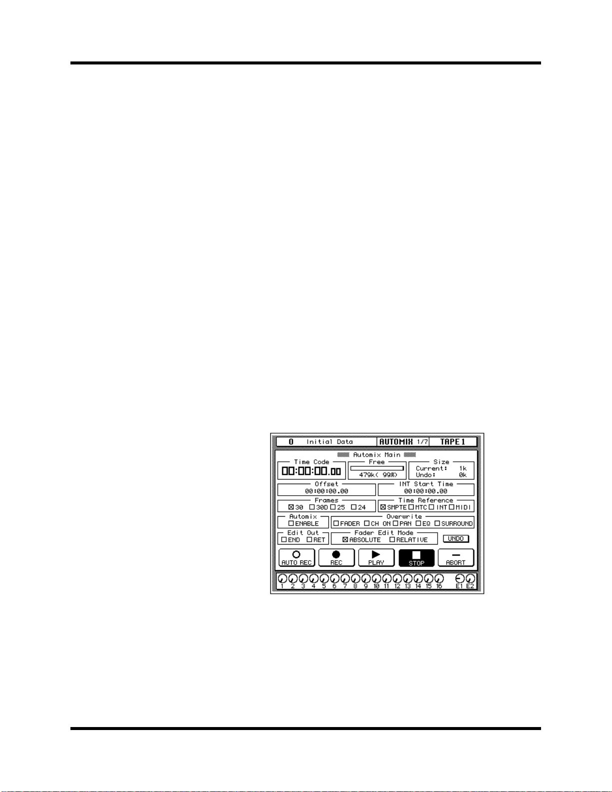
68 Mixing and Automix
What is 02R Automix?
There are three basic steps to making a multitrack recording:
• Setup and initial tracks
• Overdubbing
• Mixdown
Each step is vital in order to produce a satisfactory recording, but the most
difficult one for most engineers is the mixdown. The musicians have
finished their work. They have played their instruments and sung their
vocals. All that raw material is stored on your multitrack recorder, waiting
to be turned into a perfect final mix.
To assist you with this difficult task, the 02R has a fully-featured on-board
automix system. It memorizes fader position changes, switches individual
channels on or off, adjusts the EQ or pan positions, and changes the
auxiliary sends—all based on timecode. It can also recall scene memories
and programs from the EQ library, effects library, dynamics library, and
channel library.
This allows you to record an entire mixing session, and then edit the
individual channel settings in multiple passes until you have achieved
perfection. You can punch-in to fine tune a specific parameter or you can
use one of the event editors to adjust the timecode position of a channel
setting or scene change. You can easily create a mix that would be virtually
impossible to achieve on a standard analog mixer.
Automix Memory
02R Getting Started Guide
The 02R has a current automix buffer and 16 automix memories. There is
also an undo buffer. Only the current mix can be played back and recorded.
You can store the current mix in any of the 16 automix memories.
Page 78

Mixing and Automix 69
Real-time Automix
These tutorials have assumed you are using your 02R with one or more of
the optional I/O cards installed and a multitrack recorder connected. In
this section, you will be synchronizing your multitrack recorder to the 02R.
There are three basic ways of doing this:
• If your multitrack recorder is equipped with a SMPTE timecode output
connector, you use an audio cable to connect it to the SMPTE
TIME CODE INPUT jack on the rear panel of the 02R.
• Use an external SMPTE timecode generator if your multitrack recorder
cannot output SMPTE time. You need to record timecode onto one of
the tracks of your multitrack recorder and connect the output from that
track directly to the SMPTE TIME CODE INPUT jack on the rear panel
of the 02R.
• Use a MIDI sequencer to send MTC (MIDI timecode) or MIDI Clocks to
the 02R as well as your multitrack recorder. Connect a MIDI cable to
the MTC TIME CODE INPUT jack on the rear panel of the 02R.
There is an additional option—you can automate the 02R using its internal
timecode generator. However, you cannot synchronize with an external
device as the 02R has no timecode output connectors. This mode is effective
for learning how to use the automix system.
AUTOMIX
Basic Connections and Setup
1. Connect your timecode source to the 02R.
2. Use the [AUTOMIX] button to locate the AUTOMIX 1/7 page.
3. Use the CURSOR buttons to select the desired “Frames” rate and
press the [ENTER] button.
The 02R supports the following frame rates:
• 30—30 frames per second.
02R Getting Started Guide
Page 79

70 Mixing and Automix
• 30D—29.97 frames per second (30 drop frame).
• 25—25 frames per second.
• 24—24 frames per second.
These frame rates apply to the SMPTE, MTC, and INT time references.
4. Select the “Time Reference” with the CURSOR buttons and press
the [ENTER] button.
Select the time reference from the four options:
• SMPTE timecode (the motion picture standard)
• MTC (MIDI timecode)
• INT (internal)
• MIDI (MIDI Clock)
5. Use the CURSOR buttons to select the “Automix” ENABLE and
press the [ENTER] button to switch it on.
The automix system will not function unless this check box is enabled.
6. Select the desired “Overwrite” items with the CURSOR buttons
and press the [ENTER] button.
This field allows you to select the types of events that will be recorded.
Only the items selected will be recorded. Choose from the following:
• FADER—channel level operations (fader or encoder) including
auxiliary send levels.
• CH ON—[ON] button selections for each channel.
• PAN—pan position for each channel.
• EQ—EQ selections for each channel.
• SURROUND—surround pan events
Note: Scene memories and all library recall operations will be recorded
regardless of the settings of the “Overwrite” options.
The other options on this page are also important, but not for the purposes
of this tutorial. See “Automix Main” on page 144 of the User’s Guide for
more details.
02R Getting Started Guide
Creating a New Automix
To record an entire mixing session with the 02R automix system, you must
first create a new automix. When a new automix is created, the contents of
the current automix (referred to as “events”) are deleted and the current
automix is returned to its default settings.
Page 80

STORE
SCENE MEMORY
AUTOMIX
RECALL
Mixing and Automix 71
If you want to keep the contents of the current automix, store them into an
available memory location before proceeding.
1. Use the [AUTOMIX] button to locate the AUTOMIX 2/7 page.
2. Use the SCENE MEMORY increment or decrement buttons to
select your starting scene memory and press the [RECALL]
button.
The selected scene memory is recalled.
Your mixdown scene memory should be stored with the [FLIP] button
pressed so that the faders operate the tape returns rather than the input
channels.
Note: You can customize your 02R so that the [FLIP] button status is ignored
during scene memory recalls. In this case, you may need to press the [FLIP] button
before you start recording your automix. See “Preferences” on page 198 of the
User’s Guide for more information.
3. Set your starting levels for the mixdown and press the [STORE]
button to update the scene memory.
The 02R will display a popup confirmation request message. Select the
“EXECUTE” icon and press the [ENTER] button.
4. Use the CURSOR buttons to select the “NEW” icon and press the
[ENTER] button.
The 02R will display a popup confirmation request message asking if you
want to make a new automix. The popup has two icons: “CANCEL” and
“EXECUTE”:
02R Getting Started Guide
Page 81

72 Mixing and Automix
CANCEL is the default. To cancel the NEW operation, either press the
[ENTER] button or wait about 10 seconds—the NEW operation will be
automatically cancelled.
To create the new automix, use the CURSOR buttons to select the
“EXECUTE” icon and press the [ENTER] button. The last scene memory
that was stored or recalled will be inserted at timecode location 00:00:00.00.
02R Getting Started Guide
Page 82

AUTOMIX
Mixing and Automix 73
Recording the First Session
1. Use the [AUTOMIX] button to locate the AUTOMIX 1/7 page.
2. Select the “REC” (record) icon with the CURSOR buttons and
press the [ENTER] button.
The “REC” icon will flash, indicating AUTOMIX RECORD READY status:
3. Press the [SEL] buttons for the tape return channels you want to
record.
The LED inset in the selected channel [SEL] buttons flash indicating that
they are armed for recording.
Note: Remember the scene memory you recalled has the [FLIP] function
engaged. Therefore you should be selecting the [SEL] buttons in the row above the
faders.
4. Start the device that is providing the timecode.
It should start from a location before the music starts.
Note: The 02R automix function will not respond correctly in cases where the
source timecode starts at “23:59:30.00” and rolls over to “00:00:00.00”. The
timecode must be continuous.
When timecode is received when the 02R is in AUTOMIX RECORD
READY status, the “REC” icon is highlighted and automix recording will
02R Getting Started Guide
Page 83

74 Mixing and Automix
begin. The timecode will be displayed in real-time in the “Time Code” field
of the “Automix Main” page.
Note: If the timecode is not being displayed correctly in the “Time Code” field,
check the following:
• Are your cables connected between the timecode source device and the 02R
correctly?
• Is the timecode source device setup correctly to output timecode?
5. While monitoring the recording, operate the faders and other
controls for the selected channels.
When you are recording the automix events, you can only operate the
controls, specifically the faders, of the selected channels.
Note: The 02R tries to prevent accidental level changes by “freezing” the faders
that have not been selected. To avoid damaging the unit, do not attempt to operate
the faders of channels that have not been selected.
Automix Recording Notes
• When you are recording pan or EQ changes you may find it more
convenient to use the buttons and controls of the SELECTED
CHANNEL block.
• If you have selected more than one channel with the [SEL] buttons, the
SELECTED CHANNEL controls can only adjust the channel that was
selected last. The same applies for EQ and dynamics processor
operations. Because of these restrictions, you may find it more
convenient to work on your automix recording one channel at a time
when editing EQ and pan data.
• While you are recording automix events, you can select other 02R
display functions, allowing you to adjust the parameters for multiple
channels.
• To record a recall operation from EQ, dynamics, or channel libraries,
press the [SEL] button for the channel to be changed, then use the
corresponding display function to perform the recall operation. To
record a recall operation from the effect libraries, use the [AUX 7] or
[AUX 8] button to access the effect libraries.
02R Getting Started Guide
Page 84

Mixing and Automix 75
6. When you have completed recording the automix session, use
the CURSOR buttons to select the “STOP” icon and press the
[ENTER] button.
You may find it faster and more convenient to stop the automix recording
session by stopping the device that is providing the timecode. In this case,
the effect is the same as if you selected the STOP function on the 02R:
The “REC” icon will change to normal and the “STOP” icon is highlighted.
The events recorded during the automix session will be written to the
current automix memory.
You can also discard the events recorded during the automix session by
selecting the “UNDO” icon with the CURSOR buttons and pressing the
[ENTER] button.
You can stop the automix recording session by selecting the “ABORT” icon
with the CURSOR buttons and pressing the [ENTER] button. However, the
events recorded during the automix session will be discarded.
Note: The ABORT function must be used before an automix recording has
stopped. Once the recording has stopped, the automix data will be updated and a
new current mix is created. At this point after stopping an automix recording, the
UNDO function can be used to retrieve the previous automix data.
In most cases, punch-in edits or using the event editors can correct minor
errors.
7. Stop the device that is providing the timecode.
02R Getting Started Guide
Page 85

76 Mixing and Automix
WARNING! B
AUTOMIX
Editing Automix Events
Overwriting Events
You can overwrite the events that have been recorded into the current
automix. You can alter events on an already recorded channel or you can
record new events onto another channel. For example, you may first record
the faders for the rhythm section to the automix and then overwrite the
fader operations for the lead parts and vocals.
1. Use the [AUTOMIX] button to locate the AUTOMIX 1/7 page.
e careful
that previously recorded
events are not accidentally
overwritten when you
make these selections.
2. Use the CURSOR buttons to select the desired “Overwrite” items
and press the [ENTER] button.
Note: If you double-click the [ENTER] button on a selected “Overwrite” item,
only that item will be selected and the other items will be switched off.
3. Select the “REC” icon with the CURSOR buttons and press the
[ENTER] button.
The “REC” icon will flash.
4. Press the [SEL] buttons for the tape return channels you want to
overwrite.
It is very important that you be careful when you select the type of events
and channels that will be overwritten. If you select the same channel and
the same type of event as the last session, the previously recorded events
will be deleted the moment the automix recording begins.
5. Start the device that is providing the timecode.
It should have been rewound and again start from a location before the
music starts. The previously recorded automix will playback.
02R Getting Started Guide
Page 86

Mixing and Automix 77
6. While monitoring the recording, adjust the parameters you want
to overwrite.
7. When you have completed the automix overwriting session, use
the CURSOR buttons to select the “STOP” icon and press the
[ENTER] button.
You may find it faster and more convenient to stop the automix recording
session by stopping the device that is providing the timecode. The effect is
the same as if you selected the STOP function on the 02R.
The “REC” icon will change to normal and the “STOP” icon is highlighted.
The events recorded during the overwriting session will be added to the
current automix memory.
8. Stop the device that is providing the timecode.
Punch-in Automix Data
If you made a mistake in just one portion of the automix, you can replace
the erroneous data with a punch-in.
AUTOMIX
1. Use the [AUTOMIX] button to locate the AUTOMIX 1/7 page.
2. Use the CURSOR buttons to select the desired “Overwrite” items
and press the [ENTER] button.
3. Select the “REC” icon with the CURSOR buttons and press the
[ENTER] button.
The “REC” icon will flash.
4. Start the device that is providing the timecode.
It should have been rewound and again start from a location before the
music starts. The previously recorded automix will playback, however,
because you have not selected any channels, the 02R will remain in
AUTOMIX RECORD READY status.
02R Getting Started Guide
Page 87

78 Mixing and Automix
5. Monitor the recording. At the punch-in location, press the [SEL]
buttons for the tape return channels you want to fix.
Recording will begin from the location where you pressed the [SEL] button.
Note: From this point, new events will be recorded and previously existing
events will be deleted.
6. While monitoring the recording, adjust the parameters you want
to fix.
7. When you have finished adjusting the parameters, press the [SEL]
buttons again.
The 02R will return to AUTOMIX RECORD READY status.
Note: If you do not adjust any parameters between the punch-in and punch-out
points, any events of the selected type that were previously recorded there will have
been deleted.
AUTOMIX
8. Use the CURSOR buttons to select the “STOP” icon and press the
[ENTER] button.
You may find it faster and more convenient to stop the automix recording
session by stopping the device that is providing the timecode. The effect is
the same as if you selected the STOP function on the 02R.
The “REC” icon will change to normal and the “STOP” icon is highlighted.
9. Stop the device that is providing the timecode.
Editing Fader/Encoder Movements
If you are replacing erroneous fader/encoder data using a punch-in, the
02R allows you to monitor the differences on the Fader Edit page.
1. Use the [AUTOMIX] button to locate the AUTOMIX 1/7 page.
2. Use the CURSOR buttons to select the “FADER—Overwrite” item
and press the [ENTER] button.
02R Getting Started Guide
Page 88

Mixing and Automix 79
3. Use the [AUTOMIX] button to locate the AUTOMIX 3/7 page.
This display allows you to watch the fader movements as dynamic
bargraphs. Several features make this display convenient to use while you
perform detailed fader/encoder edits.
4. Use the CURSOR buttons to select “Fader Edit Out—RET” and press
[ENTER] to change its value.
If the RET check box is not selected, you may want to move the fader back
to its previously recorded level before you punch-out. If the RET check box
is selected, the fader will automatically return to the previously recorded
level when you punch out. The time it takes to return to the previous level
is controlled by the “Time” field.
5. Select the “REC” icon with the CURSOR buttons and press the
[ENTER] button.
The “REC” icon will flash.
6. Start the device that is providing the timecode.
The 02R will remain in AUTOMIX RECORD READY status.
7. Monitor the recording. At the punch-in location, press the [SEL]
button for the tape return channel you want to edit.
Recording will begin from where you pressed the [SEL] button.
8. While monitoring the recording, adjust the fader you want to edit.
As you operate the fader, the display shows the previously recorded
position as well as the new position. An arrow in the display indicates the
02R Getting Started Guide
Page 89

80 Mixing and Automix
direction the fader has to be moved to return to the previously recorded
position:
If the fader is moved to a position lower
than the previously recorded position
If the fader is moved to a position higher
than the previously recorded position
9. When you have finished adjusting the fader, press the [SEL] button
again.
The 02R will return to AUTOMIX RECORD READY status.
10. Use the CURSOR buttons to select the “STOP” icon and press the
[ENTER] button.
You may find it faster and more convenient to stop the automix recording
session by stopping the device that is providing the timecode. The effect is
the same as if you selected the STOP function on the 02R.
11. Stop the device that is providing the timecode.
02R Getting Started Guide
Page 90

AUTOMIX
Mixing and Automix 81
Off-line Automix Editing
Editing Scene and Library Recall Events
The Event Edit (Scene/Lib.) page, shown below, allows you to duplicate
and delete mix scene and library recall events, and insert new events.
Timecode addresses can be captured on-the-fly, and new events inserted at
the captured points. The Locate function provides a speedy way to locate
events in a complex automix.
1. Use the [AUTOMIX] button to locate the AUTOMIX 5/7 page.
Mix scene recall events and library program recall events are listed in the
Time Code, Memory, and Channel columns. Events can be moved by
editing the timecode addresses, and events are resorted automatically. In
the Memory column, event type and memory number can be edited. In the
Channel column, the channel number for EQ, dynamics, effects, and
channel library events can be edited. Mix scene events do not have a
Channel value.
2. Use the CURSOR buttons to move up or down the event list, and
the encoder wheel to edit values.
You can edit the following data:
• Time Code—the location of the event as a timecode value. The 02R
sorts events by their timecode value.
• Memory—the type of the event. You can select from the following
events:
• SCENE—scene memory recall. The number indicates the scene
number (from 0 to 96).
• EQ.Lib.—EQ library recall. The number indicates the EQ library
number (from 1 to 128).
• DY.Lib.—dynamics library recall. The number indicates the
dynamics library number (from 1 to 128).
02R Getting Started Guide
Page 91

82 Mixing and Automix
• EF.Lib.—effect library recall. The number indicates the effect
library number (from 1 to 128).
• CH.Lib.—channel library recall. The number indicates the
channel library number (from 1 to 64).
• Channel—the channel that the recall applies to. For scene memory
recall, this field is blank.
For timecode, you can independently adjust the hours, minutes, seconds,
and frames values.
3. Use the CURSOR buttons to select the DUPLICATE icon and press
the [ENTER] button to duplicate the selected event.
The selected event can be duplicated or deleted using the DUPLICATE and
DELETE icons. When the Selected CH parameter is checked, only events
corresponding to the selected channel are listed, useful for editing an
automix consisting of many events.
4. Use the CURSOR buttons to select the DELETE icon and press
[ENTER] to delete the selected event.
When the SYNC icon is pressed, events occurring around the current
timecode address are displayed. The timecode counter below the SYNC
icon displays the incoming timecode. When the CAPTURE icon below that
is pressed, the current timecode address is captured and displayed in the
window below. Up to eight timecode addresses can be captured, and they
are stored when the 02R is turned off. The parameter next to the CAPTURE
icon is used to select the addresses. When the LOCATE icon is pressed,
events occurring about the captured timecode address are displayed.
When the INSERT icon is pressed, a new scene recall event is inserted at
the captured timecode address. The new event can be edited as required.
02R Getting Started Guide
Page 92
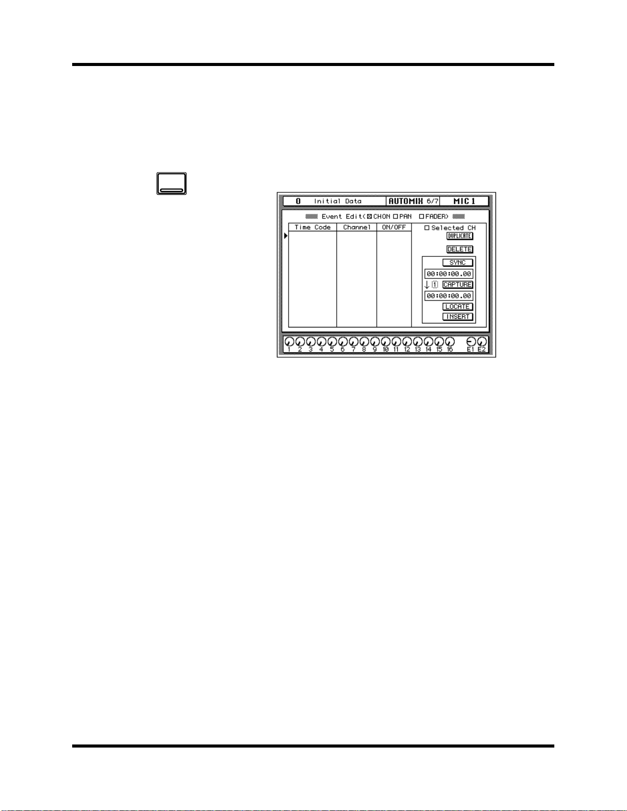
AUTOMIX
Mixing and Automix 83
Editing Channel On, Pan, & Fader events
The Event Edit (CH ON, PAN, FADER) page, shown below, allows you
edit channel on/off, pan, and fader events, and duplicate, delete, and
insert new events. Timecode addresses can be captured on-the-fly, and
new events inserted at the captured points. The Locate function provides
a speedy way to locate events in a complex automix.
1. Use the [AUTOMIX] button to locate the AUTOMIX 6/7 page.
Channel on/off, pan, and fader events are listed in the Time Code, and
Channel columns. Events can be moved by editing the timecode addresses,
and events are resorted automatically. In the Channel column, the channel
number can be edited. The value in the third column depends on the event
type selected using the CH ON (ON/OFF), PAN (L-C-R), and FADER
(dB/SEC) check boxes.
2. Use the CURSOR buttons to move up or down the event list, and
the encoder wheel to edit values.
3. Use the CURSOR buttons to select the DUPLICATE icon and press
the [ENTER] button to duplicate an event.
The selected event can be duplicated or deleted using the DUPLICATE and
DELETE icons. When the Selected CH parameter is checked, only events
corresponding to the selected channel are listed, useful for editing an
automix consisting of many events.
4. Use the CURSOR buttons to select the DELETE icon and press
[ENTER] to delete the current event.
When the SYNC icon is pressed, events occurring around the current
timecode address are displayed. The timecode counter below the SYNC
icon displays the incoming timecode. When the CAPTURE icon below that
is pressed, the current timecode addresses is captured and displayed in the
window below. Up to eight timecode addresses can be captured, and they
are stored when the 02R is turned off. The parameter next to the CAPTURE
icon is used to select the addresses. When the LOCATE icon is pressed,
events occurring around the captured timecode address are displayed.
02R Getting Started Guide
Page 93

84 Mixing and Automix
When the INSERT icon is pressed, a new event is inserted at the captured
timecode address. The type of event depends on which of the CH ON,
PAN, FADER check boxes is checked. The new event can be edited as
required.
02R Getting Started Guide
Page 94

AUTOMIX
Mixing and Automix 85
Erasing Events
The Event Copy page, shown below, allows you to copy, move, erase and
trim the level of automix events. In this tutorial just the Erase function is
used. See “Event Copy” on page 153 of the User’s Guide for information
about the other functions.
1. Use the [AUTOMIX] button to locate the AUTOMIX 4/7 page.
The channel icons are used to select the channels whose automix data is to
be edited.
2. Use the CURSOR buttons to select the channel check boxes, and
press the [ENTER] button to check them.
The Parameter check boxes are used to select parameters for editing, and
multiple parameters can be selected. The parameters are:
• FADER—Channel input and output level events (faders/rotary
encoders)
• CH ON—Channel on/off (mute) events
• PAN—pan events
• EQ—EQ events
• SCENE—Scene memory recall events
• AUX 1–8—Channel aux send events (faders/rotary encoders)
• REMOTE 1–4—MIDI Remote events
• SURR—Surround pan events
• EQLIB—EQ library program recall events
• CHLIB—Channel library program recall events
• DYLIB—Dynamics library program recall events
• EFLIB—Effects library program recall events
3. Use the CURSOR buttons to select the parameter check boxes,
and press the [ENTER] button to check them.
02R Getting Started Guide
Page 95

86 Mixing and Automix
4. Use the CURSOR buttons and encoder wheel to set the In Time.
5. Use the CURSOR buttons and encoder wheel to set the Out Time.
The Extract function allows you to delete the selected parameters from
the selected channels between the In Time and Out Time points.
6. Use the CURSOR buttons to select the “ERASE” icon and press the
[ENTER] button.
A confirmation dialog box appears.
7. Select EXECUTE and press the (ENTER) button.
The events are deleted. If you change your mind, you can restore the
deleted events using the Undo function. You can undo only the last
operation.
02R Getting Started Guide
Page 96

AUTOMIX
Mixing and Automix 87
Using the Automix Library
Storing an Automix
An automix can be stored in one of the 16 automix memories available on
the Memory Management page shown below.
1. Use the [AUTOMIX] button to locate the AUTOMIX 2/7 page.
2. Use the CURSOR buttons to select the TITLE EDIT box.
3. Use the CURSOR buttons to move the cursor within the title, and
the encoder wheel to select the characters.
Automix titles can be up to 16 characters long, and the following characters
are available.
!“#$%&'()*+,-./
0123456789: ;<=>?
@ABCDEFGH I JKLMNO
PQRSTUVWXYZ[\]^_
`abcdefghi j k lmno
pq r s t uvwxyz{ | }~
You can select the “INS.” icon to insert a space at the cursor position in the
TITLE EDIT box. Select the icon with the CURSOR buttons and press the
[ENTER] button. The “DEL.” icon is used to delete the character at the
cursor position in the TITLE EDIT box.
Note: The “COPY” and “PASTE” icons allow you to select the title from
another automix program and paste it into your program for subsequent editing.
These icons only copy the title. See “AUTOMIX Name Edit Functions” on page
149 of the User’s Guide.
02R Getting Started Guide
Page 97

88 Mixing and Automix
4. Use the CURSOR buttons to select the STORE icon. Use the
encoder wheel to select an automix and press the [ENTER]
button.
The 02R will display a popup confirmation request message asking if you
want to store your settings in the selected automix program. The popup
has two icons: “CANCEL” and “EXECUTE”.
CANCEL is the default. To cancel the STORE operation, either press the
[ENTER] button or wait about 10 seconds—the STORE operation will be
automatically cancelled.
To store your settings, use the CURSOR buttons to select the “EXECUTE”
icon and press the [ENTER] button. The automix is stored.
Automix Memory
Automix memory is shared between the current automix and the stored
automixes. This means that a “Memory Full” error message could appear
even though there are empty automix locations. A complex automix,
containing many events, may exceed the memory capacity. If this occurs,
backup and delete any unused automixes and attempt the STORE
operation again.
The default capacity of the 02R automix memory is 480K. You can expand
this to 1.5 MB or 2.5 MB by installing the optional ME4M memory
expansion kits.
02R Getting Started Guide
Page 98

AUTOMIX
Mixing and Automix 89
Recalling an Automix
1. Use the [AUTOMIX] button to locate the AUTOMIX 2/7 page.
2. Use the CURSOR buttons to select the RECALL icon. Use the
encoder wheel to select an automix.
The 02R will scroll through the available automixes. The program that is
highlighted will be recalled when you press the [ENTER] button.
3. Press the [ENTER] button.
The 02R will display a popup confirmation request message asking if you
want to recall selected automix program. The popup has two icons:
“CANCEL” and “EXECUTE”.
CANCEL is the default. To cancel the RECALL operation, either press the
[ENTER] button or wait about 10 seconds—the RECALL operation will be
automatically cancelled.
To recall the automix, use the CURSOR buttons to select the “EXECUTE”
icon and press the [ENTER] button. The automix program is recalled.
Note: When you recall an automix program, you are overwriting the current
automix. Make sure that you have backed up or stored the current automix just in
case.
YOU SHOULD ALWAYS BE CAREFUL WHEN THE 02R DISPLAYS ITS
CONFIRMATION POPUP MESSAGE!
02R Getting Started Guide
Page 99

90 Index
Index
A
Attenuation 22
Audio quality 2
Automix
about 7
editing 76
editing faders and encoders 78
editing scene and library recalls
81
extracting events 85
frame rate 69
making new automixes 70
memories 68
memory expansion 88
off-line editing 81
overwriting 76
punch-in 77
real-time operation 69
recalling automixes 89
recording 73
recording notes 74
setup 69
storing automixes 87
time reference 69
titling 87
what is it? 68
Aux sends
about 42
AUX buttons 42
selected channel AUX controls
42
setting send levels 43
B
Basic setup 15
C
Compander 54
Compressor 54
Converters 11
Crystal clarity 2
D
Deleting events 85
Digital audio, benefits 10
Display 8
DSP 2
Ducking 54
Dynamics
about 9
compander 54
compressor 54
ducking 54
editing programs 58
expander 54
gate 54
library 57
recalling programs 57
stereo output 55
storing programs 59
titling programs 59
E
Editing
automix events 76
dynamics programs 58
effects 50
faders and encoders 78
on/off, pan, and fader events 83
scene and library recalls 81
Effects
about 9
editing 50
recalling programs 49
returns 47
send levels 46
storing user programs 51
titling 51
using 46
EQ
about 10
applying 24
bandwidth 28
frequency 27
gain 25
library 30
on/off 24
Q 28
recalling programs 30
resetting 29
storing programs 32
titling programs 32
undo 31
Erasing events 85
Expander 54
F
Faders 9
editing events 83
level setting 20
Features 5
Frame rate, automix 69
Frequency, EQ 27
G
Gain control, setting 21
Ganging pans 39
Gate 54
I
Initial data 62
Input level, setting 20
Installation 3
Interface, about 8
Internal effects, about 9
I/O cards 2
L
LCD 8
Library
dynamics 57
effects 49
EQ 30
M
Memory expansion kit 88
MIDI Clock 69
Monitoring 45
Monitor source, setting 20
Motorized faders 9
MTC 69
Muting channels 23
02R Getting Started Guide
Page 100

Index 91
N
Naming See Titling.
Noise gate 54
O
Off-line editing 81
ON buttons 23
On/off event editing 83
Options 6
Overwriting automix events 76
P
Pad 21
Pan
about 38
editing events 83
ganging 39
setting 38
Parametric EQ, about 10
Peak hold 22
Phase 22
Powering on/off 16
Programs
dynamics 57
effects 49
EQ 30
Punch-in, automix 77
Q
Q, EQ 28
selecting 37
using 36
S
Scene memories
about 7
editing recall events 81
indicator 23
recalling 65
recalling scene 0 17
storing 62
titling 63
Scene memory buttons 62
Scene 0 17
Setting
aux send levels 43
effects send levels 46
EQ 24
fader levels 20
gain controls 21
input levels 20
monitor source 20
pan 38
SMPTE 69
Snapshots 62
Sonic performance 2
Storing
automixes 87
dynamics programs 59
effects programs 51
EQ programs 32
scene memories 62
Switching the 02R on/off 16
U
Undo
EQ recall 31
User guides, about 3
User interface, about 8
W
Wordclock 16
Z
02R
features 5
installation 3
options 6
rear panel 4
top panel 4
R
Rear panel 4
Recalling
automixes 89
dynamics programs 57
effects programs 49
EQ programs 30
scene memories 65
Resetting the EQ 29
Returns, effects 47
RISC technology 3
Routing
about 35
T
Time reference, automix 69
Titling
automixes 87
dynamics programs 59
effects programs 51
EQ programs 32
scene memories 63
Top panel 4
turning channels on/off 23
Turning the 02R on/off 16
02R Getting Started Guide
 Loading...