

Yamaha CRX-TS10, CRX-TS20, NX-TS10, NX-TS20 Owner's Manual
E
\f\\\\I"HA
illll\llii:illll:~~t~'O
(~15
'$.'J.;.;
..
~.~~.{,.;:i./.:%i.Z£,'.!!,.·.".:!.if.:M:.;,.!!,.'.f'.{~,.'.f
.•
',;.f,.:
.•,
.•..
i.
"'\"
...
~o
i!!f!i;;JJ!W"~
/!//:",:oi,j'/:.-i;·.---.··
TABLETOP
STEREO,.nl
SYSTEM
HIFI
TABl,lmi
OWNER'S
MODE;P'~
BEDIENUNGSANE.",i.·,E.f..,.·.,.·
....
~ilni.
BRUKSAN'VISr
MANUALE
DI
IS"F..'
MANUAL
DE
INSTRU
GEBRUIKS
CAUTION
Use of controls or adjustments or performance of
procedures other than those specified herein may
result in hazardous radiation exposure.
ATTENTION
Cemploi de commandes, de reglages ou un choix
de procedures differents des specifications de cette
brochure peut entrainer une exposition a
d’eventuelles radiations pouvant etre dangereses.
ACHTUNG
Die Verwendung von Bedienungselementen oder
Einstellungen oder die Durchfuhrung von
Bedienungsvorgangen, die nicht in dieser Anleitung
aufgefijhrt sind, kann zu einem Kontakt mit
gefahrlichen Laserstrahlen fuhren.
OBSERVERA
Anvandning av kontroller och justeringar eller
genomfdrande av andra procedurer an de som
specificeras i denna bok kan resultera i att du
utsatter dig for farlig straining.
ATTENZIONE
Uso di controlli o regolazioni o procedure non
specificamente descritte puo causare I’esposizione
a radiazioni di livello pericoloso.
PFlECAUCldN
El uso de 10s controles o 10s procedimientos de
ajuste o utilization diferentes de 10s especificados
en este manual pueden causal una exposition
peligrosa a la radiation.
VOORZICHTIG
Gebruik van bedieningsorganen of instellingen, of
uitvoeren van handelingen anders dan staan
beschreven in deze handleiding kunnen leiden tot
blootstelling aan gevaarlijke stralen.
VARO!
AVATTAESSA JA SUOJALUKITUS
OHITETTAESSA OLET ALTTIINA
NiiKYMiiTToMiiLLE LASERSiiTEILYLLE. iiLii
KATSO SLiTEESEEN.
VARNING!
OSYNLIG LASERSTRALNING NliR DENNA DEL
AR~PPNAD~CHSPARRENARURK~PPLAD.
BETRAKTA EJ STRALEN.
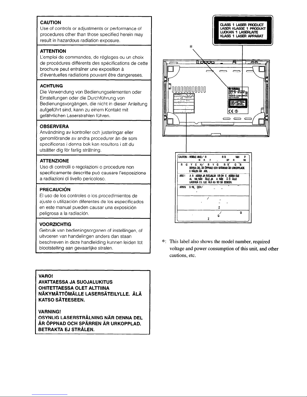
*: This label also shows the model number, required
voltage and power consumption of this unit, and other
cautions, etc.
ARNNSN\.
I)!lil
.."
=n
CE:
®
==
I
"
..
..
Z
I
Q
Q
Z
II.:::::~~.
II.~
......
-.
CLASS1LASER
PRODUCT
LASER
KIASSE1PRODUKT
LUOKAN1LASERLAITE
KLASS
1
LASER
APPARAT
,-
.~
RGYGH/RYG
RR
G"R
[EljNA
00.
All
lmWl00i
SPARRAR
All
lJlKllPPlAIE.
s
RAwJ
All
ARL
.
ARC
! AA
AE5SA.v.
SOOJALlJ(
us
DHEAE5SA
IU
AL
NA
~
IW.E
JA
A
~
AO
IW.E
LASERSll
EL
1.1£.
lI1Jl
KA
so
slI
EESEEN.
CAUI1lJ'J•V9IIlE
ANDI
R RR IMi P
R K F
)(Jl
R M
*:
This label also shows the model number, required
voltage and power consumption
of
this unit, and other
cautions, etc.
CAUTION
Use of controls or adjustments or performance of
procedures other than those specified herein may
result
in
hazardous radiation exposure.
ATTENTION
L'emploi de commandes, de reglagesouun choix
de procedures differents des specifications de cette
brochure peut entrainer une exposition
a
d'eventuelles radiations pouvant etre dangereses.
ACHTUNG
Die Verwendung von Bedienungselementen oder
Einstellungen oder die DurchfOhrung von
Bedienungsvorgangen, die nicht
in
dieser Anleitung
aufgefOhrt sind, kann
zu
einem Kontakt mit
gefahrlichen Laserstrahlen
fOhren.
OBSERVERA
Anvandning av kontroller och justeringar eller
genomforande av andra procedurer
an
de som
specificeras
i denna bok kan resultera i att du
utsatter dig for farlig straining.
ATTENZIONE
Uso di controlli 0 regolazioni 0 procedure non
specificamente descritte
pUb
causare I'esposizione
a radiazioni di Iivello pericoloso.
PRECAUCION
EI
uso de los controles 0 los procedimientos de
ajuste
0 utilizaci6n diferentes de los especificados
en
este manual pueden causar una exposici6n
peligrosa a
la
radiaci6n.
VOORZICHTIG
Gebruik van bedieningsorganen of instellingen, of
uitvoeren van handelingen anders dan staan
beschreven
in
deze handleiding kunnen leiden tot
blootstelling aan gevaarlijke stralen.
VAROI
AVATTAESSA JA SUOJALUKITUS
OHITETTAESSA OLET ALTTIINA
NAKYMATTOMALLE LASERSATEILYLLE. ALA
KATSO SATEESEEN.
VARNING!
OSYNLlG LASERSTRALNING NAR DENNA DEL
AR OPPNAD OCH SPARREN AR URKOPPLAD.
BETRAKTA
EJ
STRALEN.
Thank you for purchasing this YAMAHA product. We
hope it will give you many years of trouble-free
enjoyment. For the best performance, read this manual
carefully. It will guide you in operating your YAMAHA
product.
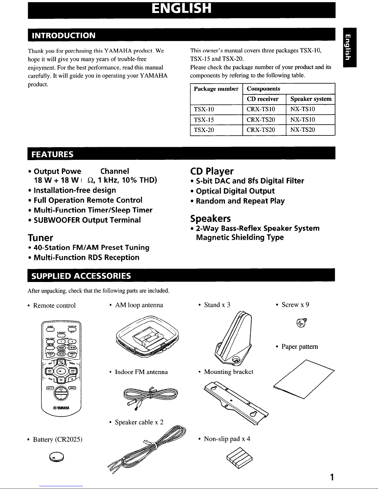
This owner’s manual covers three packages TSX-10,
TSX- 15 and TSX-20.
Please check the package number of your product and its
components by refering to the following table.
Package number Components
CD receiver Speaker system
TSX-10
CRX-TS 10 NX-TS 10
TSX-15
CRX-TS20
NX-TS 10
TSX-20
CRX-TS20
NX-TS20
l
Output Powe
Channel
18
W + 18 W ( R, 1 kHz, 10% THD)
l
Installation-free design
l
Full Operation Remote Control
l
Multi-Function Timer/Sleep Timer
l
SUBWOOFER Output Terminal
Tuner
l
40-Station FM/AM Preset Tuning
l
Multi-Function RDS Reception
CD Player
l
S-bit DAC and 8fs Digital Filter
l
Optical Digital Output
l
Random and Repeat Play
Speakers
l
2-Way Bass-Reflex Speaker System
Magnetic Shielding Type
After unpacking, check that the following parts are included.
l
Remote control
l
AM loop antenna
l
Stand x 3
l
Indoor FM antenna
l
Battery (CR2025)
Q
I
l
Speaker cable x 2
l
Mounting bracket
0
.
\
0
0
l
Screw x 9
CY
+
l
Paper pattern
ic;’
l
Non-slip pad x 4
1
ENGLISH
INTRODUCTION
Thank you for purchasing this YAMAHA product. We
hope it will give you many years
of
trouble-free
enjoyment. For the best performance, read this manual
carefully.
It
will guide you in operating your YAMAHA
product.
This owner's manual covers three packages TSX-lO,
TSX-15 and TSX-20.
Please check the package number
of
your product and its
components by refering to the following table.
Package number Components
CD receiver
Speaker system
TSX-IO CRX-TSIO NX-TSIO
TSX-15 CRX-TS20
NX-TSIO
TSX-20 CRX-TS20 NX-TS20
FEATURES
• Output Powe Channel
18 W
+ 18 W I
0,
1 kHz, 10% THD)
• Installation-free design
•
Full
Operation Remote Control
• Multi-Function Timer/Sleep Timer
• SUBWOOFER Output Terminal
Tuner
• 40-Station
FM/AM
Preset Tuning
• Multi-Function
RDS
Reception
CD
Player
• S-bit
DAC
and 8fs Digital Filter
• Optical Digital Output
• Random and Repeat Play
Speakers
• 2-Way Bass-Reflex Speaker System
Magnetic Shielding Type
SUPPLIED ACCESSORIES
After unpacking, check that the following parts
are
included.
• Remote control
• AM loop antenna
• Stand x 3 • Screw x 9
1
• Paper pattern
• Mounting bracket
• Non-slip pad x 4
• Indoor FM antenna
• Speaker cable x 2
@YAMAHA
• Battery (CR2025)
Front panel ..........................................................
.4
Display..
..............................................................
.4
Remote control
....................................................
5
Connections
.........................................................
6
Installation
...........................................................
8
CD preventive
care
............................................
10
Remote
control ..................................................
1 1
Setting
the clock ................................................
12
Adjusting the brightness of the display
.............
12
CD play.. ............................................................
14
Selecting the
time display..
................................
15
Random-sequence play
......................................
15
Repeat play ........................................................
16
Listening to the
radio.. .......................................
17
Presetting stations
..............................................
18
Receiving RDS
data ..........................................
19
PTY SEEK mode..
............................................
.20
Optional settings for RDS
functions
................
.21
Timer play ........................................................
.22
Sleep timer.. ......................................................
.23
Troubleshooting
.................................................
24
Specifications
...................................................
.26
When not using the stands
When using the stands
50mm
2l
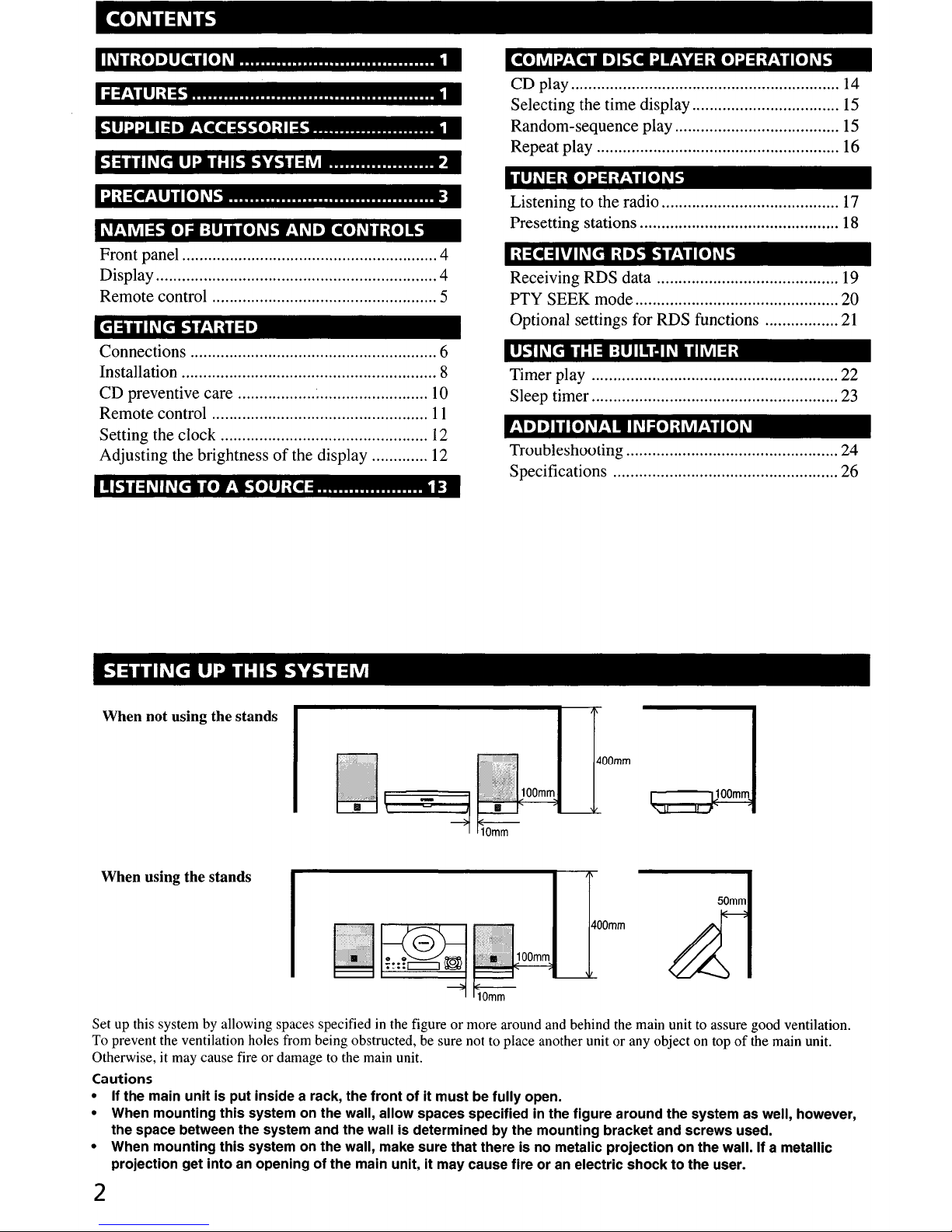
Set up this system by allowing spaces specified in the figure or more around and behind the main unit to assure good ventilation.
To prevent the ventilation holes from being obstructed, be sure not to place another unit or any object on top of the main unit.
Otherwise, it may cause fire or damage to the main unit.
Cautions
l
If the main unit is put inside a rack, the front of it must be fully open.
l
When mounting this system on the wall, allow spaces specified in the figure around the system as well, however,
the space between the system and the wall is determined by the mounting bracket and screws used.
l
When mounting this system on the wall, make sure that there is no metalic projection on the wall. If a metallic
projection get into an opening of the main unit, it may cause fire or an electric shock to the user.
2
CONTENTS
INTRODUCTION 1
FEATURES 1
SUPPLIED ACCESSORIES 1
SETTING UP THIS SYSTEM 2
PRECAUTIONS
3
NAMES
OF
BUTTONS
AND
CONTROLS
Front panel 4
Display 4
Remote control 5
GETTING STARTED
Connections 6
Installation 8
CD preventive care
~
10
Remote control
11
Setting the clock
12
Adjusting the brightnessofthe display 12
LISTENING TO A SOURCE
13
SETTING UP THIS SYSTEM
When not using the stands
COMPACT DISC PLAYER OPERATIONS
CD play 14
Selecting the time display
15
Random-sequence play
15
Repeat play 16
TUNER OPERATIONS
Listening to the radio
17
Presetting stations 18
RECEIVING RDS STATIONS
Receiving RDS data 19
PTY SEEK mode 20
Optional settings for RDS functions
21
USING THE BUILT-IN TIMER
Timer play 22
Sleep timer 23
ADDITIONAL
INFORMATION
Troubleshooting 24
Specifications 26
When using the stands
400mm
....----.100mm
SWd
10mm
50mm
400mm
Set up this system by allowing spaces specifiedinthe figure or more around and behind the main unit to assure good ventilation.
To prevent the ventilation holes from being obstructed, be sure not to place another unit or any object on top
of
the main unit.
Otherwise, it may cause fire or damage to the main unit.
Cautions
• If the main
unit
is put inside a rack, the frontofit
must be fUlly open.
• When mounting
this
system on the wall, allow spaces specified in the figure around the system as well, however,
the space between the system and the wall is determined by the mounting bracket and screws used.
• When mounting this system on the wall, make sure that there is no metalic projection on the wall. If a metallic
projection get into
an
openingofthe main unit,itmay cause fireoran electric shocktothe user.
2
1
2
3
4
5
6
7
8
9
10
11
12
13
14
To assure the best performance, please read this manual
carefully. Keep it in a safe place for future reference.
To avoid humming sounds, position this system away
from other electrical appliances, motors and
transformers. To prevent fire or electrical shock, do not
place this system where it may get exposed to rain or
any kind of liquid.
Avoid extreme temperature fluctuations or excessive use
of a humidifier in the room where this system is
installed to prevent condensation inside this system,
which may cause an electrical shock, fire damage to this
unit, and/or personal injury.
In order not to obstruct heat radiation, do not cover the
main unit with a newspaper, a tablecloth, a curtain, etc.
If the temperature inside the main unit rises, it may
cause fire, damage to the main unit and/or personal
injury.
Avoid installing this system in a place where foreign
objects and liquid might fall. It might cause a fire,
damage to this system and/or personal injury. Do not
place the following objects on this system:
l
Other components, as they may cause damage and/or
discolor the surface of this system.
l
Burning objects (i.e., candles), as they may cause fire,
damage to this system and/or personal injury.
l
Containers with liquid in them, as they may cause an
electrical shock to the user and/or
damage
to
this system.
Do not use force on switches, controls or connection
cables. Never pull the cables when disconnecting them.
Only the voltage specified on the main unit must be
used. Using this system with a higher voltage than
specified is dangerous and may result in fire or other
accidents. YAMAHA will not be held responsible for
any damage resulting from the use of this system with a
voltage
other than that specified.
Placing the speakers on the same shelf or rack as the
turntable can result in howling.
Secure placement or installation is the owner’s
responsibility.
YAMAHA shall not be liable for any accident caused by
improper placement or installation of this system.
Any
time you note distortion,
reduce the volume to a
lower setting. Never allow the amplifier to be driven
into “clipping”. Otherwise the speakers may be
damaged.
Do not attempt to clean this system with chemical
solvents;
this might damage the finish. Use
a clean, dry
cloth.
Disconnect the power cord from the wall outlet when
not planning to use this system for a long period of time,
or
during an electrical storm, as it could be damaged by
lightning.
Do not attempt to modify or fix this system yourself.
Contact qualified YAMAHA service personnel when
any service is needed. The cabinet should never be
opened for any reason.
Be sure
to read the “Troubleshooting” section regarding
common operating errors before concluding that this
system is faulty.
The main unit is not disconnected from the AC power
source as long as it is connected to the wall outlet, even
if the unit itself is turned off. This state is called the
standby mode. In this state, the unit is designed to
consume a very small quantity of power.
CAUTION FOR CARRYING THE MAIN UNIT
Before carrying the main unit, first remove the disc
from the unit, press
STANDBY/ON
to turn the unit
off, then disconnect the AC power plug from the
wall outlet.
SPECIAL INSTRUCTIONS FOR U.K. MODEL
IMPORTANT:
The wires in the mains lead are coloured in accordance
with the following code:
Blue: NEUTRAL
Brown: LIVE
As the colours of the wires in the mains lead of this
apparatus may not correspond with the coloured
markings identifying the terminals in your plug,
proceed as follows: The wire which is coloured BLUE
must be connected to the terminal which is marked
with the letter N or coloured BLACK. The wire which
is coloured BROWN must be connected to the terminal
which is marked with the letter L or coloured RED.
Making sure that neither core is connected to the earth
terminal of the three pin plug.
For U.K. customers
If the socket outlets in the home are not suitable for the
plug supplied with this appliance, it should be cut off and
an appropriate 3 pin plug fitted. For details, refer to the
instructions described above.
Note:
The plug severed from the mains lead must be
destroyed, as a plug with bared flexible cord is hazardous
if engaged in a live socket outlet.
CAUTION
Use of controls or adjustments or performance of
procedures other than those specified herein may
result in hazardous radiation exposure.
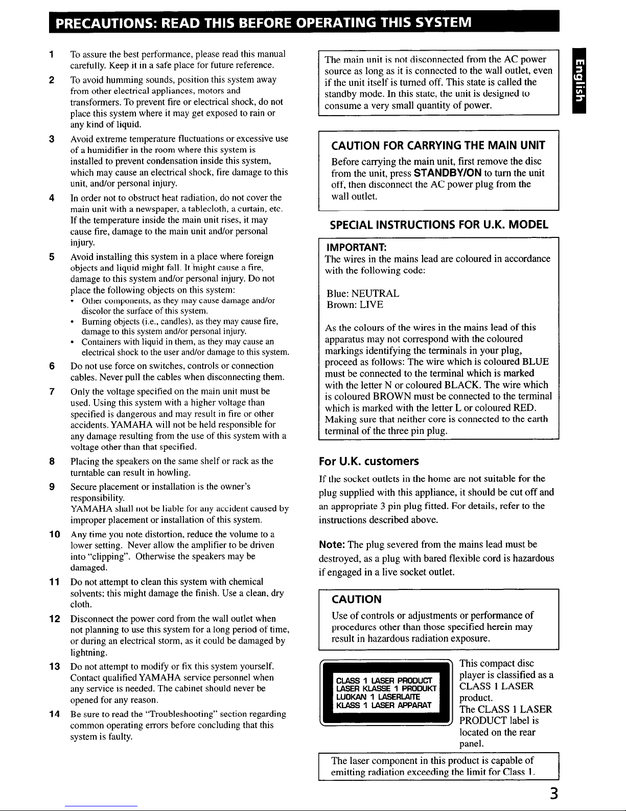
CLASS 1 LASER PRODUCT
ASER KIASSE 1 PRODUKT
LUOKAN 1 LA!iiERLAlTE
KLA!Zi 1 LASER APPARAT
This compact disc
player is classified as a
CLASS 1 LASER
product.
The CLASS 1 LASER
PRODUCT label is
located on the rear
panel.
The laser component in this product is capable of
emitting radiation exceeding the limit for Class 1.
3
PRECAUTIONS: READ THIS BEFORE OPERATING THIS SYSTEM
CAUTION
This compact disc
player is classified as a
CLASS I
LASER
product.
The CLASS I
LASER
PRODUCT
label is
located on the rear
panel.
CLASS1LASER
PRODUCT
LASER
KLASSE1PRODUKT
LUOKAN1LASERLAITE
KLASS1LASER
APPARAT
Useofcontrolsoradjustmentsorperformance
of
procedures other than those specified herein may
result in hazardous radiation exposure.
IMPORTANT:
The
wires in the mains lead are coloured in accordance
with the following code:
The
main unit is not disconnected from the AC
power
source as long as it is connected to the wall outlet, even
if
the unit itself is turned off. This state is called the
standby mode. In this state, the unit is designed to
consume a very small quantity
of
power.
CAUTION
FOR
CARRYING
THE
MAIN
UNIT
Before carrying the main unit, first remove the disc
from the unit, press
STANDBY/ON to turn the unit
off, then disconnect
theACpower
plug from the
wall outlet.
SPECIAL
INSTRUCTIONS
FOR
U.K. MODEL
As
the coloursofthe wires in the mains leadofthis
apparatus may not correspond with the coloured
markings identifying the terminals in your plug,
proceed as follows:
The
wire which is coloured
BLUE
must be connected to the terminal which is marked
with the letter N
or
coloured BLACK. The wire which
is coloured
BROWN
mustbeconnected to the terminal
which is marked with the letter L
or
coloured RED.
Making sure that neither core is connected to the earth
terminal
of
the three
pin
plug.
Blue:
NEUTRAL
Brown:
LIVE
For
U.K.
customers
If
the socket outlets in the
home
are not suitable for the
plug supplied with this appliance, it should be cut
off
and
an appropriate 3 pin plug fitted.
For
details, refer to the
instructions described above.
Note: The plug severed from the mains lead must
be
destroyed, as a plug with bared flexible cord is hazardous
if
engaged in a live socket outlet.
1
To
assure the best performance, please read this manual
carefully. Keep
it
in
a safe place for future reference.
2
To
avoid humming sounds, position this system away
from other electrical appliances, motors and
transformers.
To
prevent fire or electrical shock, do not
place this system where
it
may get exposedtorain or
any kind
of
liquid.
3 Avoid extreme temperature fluctuations or excessive use
of
a humidifier in the room where this system
is
installed to prevent condensation inside this system,
which may cause
an
electrical shock, fire damagetothis
unit, and/or personal injury.
4 In order not
to
obstruct heat radiation,donot cover the
main unit with a newspaper, a tablecloth, a curtain, etc.
If
the temperature inside the main unit rises,itmay
cause fire, damage
to
the main unit and/or personal
injury.
5 Avoid installing this system
in
a place where foreign
objects and liquid might fall.
It
might cause a fire,
damage
to
this system and/or personal injury. Do not
place the following objects on this system:
• Other components,
as
they
may
cause damage and/or
discolor
the
surface of
this
system.
• Buming objects (i.e., candles),
as
they
may
cause
fire,
damagetothis
system and/or personal
injury.
• Containers
with
liquidinthem,asthey
may
cause
an
electrical shocktothe
user and/or
damagetothis
system.
6 Do not use force on switches, controls or connection
cables. Never pull the cables when disconnecting them.
7 Only the voltage specified on the main unit must
be
used. Using this system with a higher voltage than
specified
is
dangerous and may resultinfire or other
accidents. YAMAHA will not be held responsible for
any damage resulting from the use
of
this system with a
voltage other than that specified.
8 Placing the speakers on the same shelfor rack
as
the
turntable can result
in
howling.
9 Secure placement or installation
is
the owner's
responsibility.
YAMAHA shall not be liable for any accident caused by
improper placement or installation
of
this system.
10
Any time you note distortion, reduce the volumetoa
lower setting. Never allow the amplifier
tobedriven
into "clipping". Otherwise the speakers may be
damaged.
11
Do not attempt to clean this system with chemical
solvents; this might damage the finish. Use a clean, dry
cloth.
12 Disconnect the power cord from the wall outlet when
not planning to use this system for a long period
of
time,
or during
an
electrical storm,asit
couldbedamaged by
lightning.
13 Do not attempt
to
modify or
fix
this system yourself.
Contact qualified YAMAHA service personnel when
any service is needed. The cabinet should never be
opened for any reason.
14 Be sure
to
read the "Troubleshooting" section regarding
common operating errors before concluding that this
system is faulty.
The laser component in this product is capable
of
emitting radiation exceeding the limit for Class
1.
3
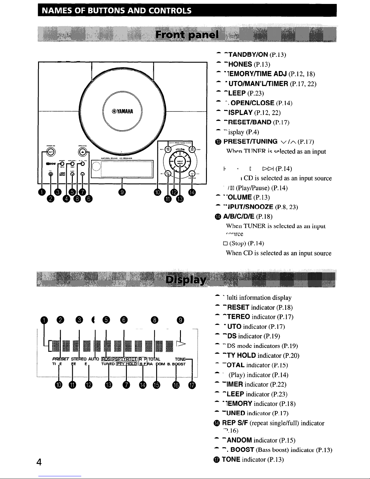
- -TANDBY/ON (P. 13)
- -HONES (P.13)
- ‘lEMORY/TIME ADJ (P.12, 18)
- - UTO/MAN’L/TIMER (P.17,22)
- -LEEP (P.23)
- A. OPEN/CLOSE (P.14)
- ‘ISPLAY (P.12,22)
- -RESET/BAND (P.17)
- - isplay (P.4)
0 PRESET/TUNING V/A (P.17)
When
TT TNER is elected as an
input
I- - c
DI>I (P. 14)
I CD is selected as an input source
100 (Play/Pause) (P.14)
- “OLUME (P. 13)
- “JPUT/SNOOZE (P.8,23)
@ A/B/C/D/E (P. 18)
When TUNER is selected as an input
--vrce
q
(Stop) (P.14)
When CD is selected as an input source
- 1 lulti information display
- ‘RESET indicator (P. 18)
- ^TEREO indicator (P.17)
- - UT0 indicator (P. 17)
- -DS indicator (P. 19)
- - DS mode indicators (P. 19)
- -LEEP indicator (P.23)
- - 1EMORY indicator (P. 18)
- ‘UNED indicator (P.17)
Q REP S/F (repeat single/full) indicator
‘-‘. 16)
- ‘ANDOM indicator (P. 15)
- -. BOOST (Bass boost) indicator (P. 13)
(D TONE indicator (P. 13)
4
NAMES
OF BUTTONS
AND
CONTROLS
- -TANDBY/ON (P.13)
- -HONES (P.13)
- ·lEMORYITIME
ADJ
(P.12, 18)
- . UTO/MAN'LlTIMER (P.I?, 22)
-
-lEEP
(P.23)
- A;OPEN/ClOSE(P.14)
-
-ISPlAY
(P.12, 22)
- -RESET/BAND (P.I?)
-
-isplay
(PA)
C&
PRESETITUNING v /A (P.1?)
Whpn
TT
TNFR
j,;;
,;;plected
as an input
r l>l>l (P.14)
I CD
is
selected as an input source
.
100
(Play/Pause) (P.14)
- .'OlUME (P.13)
- ··IPUT/SNOOZE (P.8, 23)
• AlB/C/D/E (P.18)
When TUNER
is
selectedasan input
o (Stop) (P.14)
When CD
is
selected as an input source
4
- - lulti information display
- -RESETindicator (P.18)
- -TEREO indicator (P.I?)
- . UTO indicator
(P.I?)
-
-OS
indicator (P.19)
-
-DS
mode indicators (P.19)
-
-TY
HOLD indicator (P.20)
-
-OTAl
indicator (P.IS)
_.
(Play) indicator (P.14)
-
-IMER
indicator (P.22)
-
-lEEP
indicator (P.23)
- ·lEMORY indicator (P.18)
-
-UNED
indicator (P.I?)
•
REP
S/F (repeat single/full) indicator
'").16)
- - ANDOM indicator (P.IS)
-
-.
BOOST (Bass boost) indicator (P.13)
• TONE indicator (P.13)
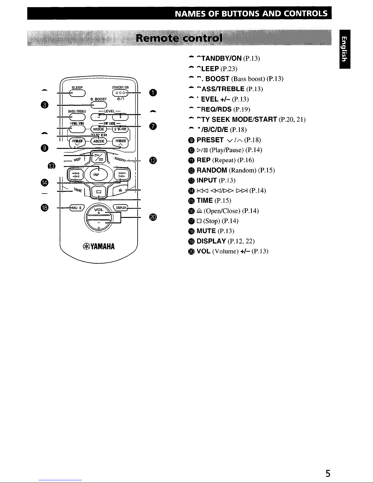
- -TANDBY/ON (P. 13)
- -LEEP (P.23)
- -. BOOST (Bass boost) (P.13)
0
LL
0
@
- -ASS/TREBLE (P. 13)
- ’ EVEL +/- (P. 13)
- ‘REWRDS (P.19)
- “TY SEEK MODE/START (P.20,21)
- - /B/C/D/E (P. 18)
@ PRESET v /A (P.18)
@
D/O0
(Play/Pause) (P.14)
@ REP (Repeat) (P.16)
@ RANDOM (Random) (P.15)
@ INPUT (P.13)
@ lc-4 da&D DDI (P.14)
@ TIME (P.15)
@ A (Open/Close) (P. 14)
@ Cl (Stop) (P.14)
@ MUTE (P. 13)
@ DISPLAY (P.12,22)
@ VOL (Volume) +/- (P.13)
5
r:
SLEEP
STANDBY/~
0
-~
(000-3
II
B.
BOOST <!>/I
.
~
II
BASS/TREBLE
-LEVEL-
-
-c::=)
C0
L:.J
II
II
fRll/RiS
-R!SIE-
•
-II
MODE
~l1lRT
.......
"'111\1
ER
II PRBB"
AB~OE
PRBB"
• V
"'-
III
:=::!1%)t--l
•
e
li~(~j
f~llG5
--'I
•
-~G))I:
~
~'
@YAMAHA
NAMES
OF BUTTONS
AND
CONTROLS
- TANDBY/ON (PoI3)
- LEEP (Po23)
-
-.
BOOST (Bass boost)
(Po
13)
-
-ASSITREBLE
(PoI3)
- . EVEL
+1-
(PoI3)
- -REQ/RDS (PoI9)
- "'TY SEEK MODE/START (P020, 21)
- alBICIDIE (PolS)
.,
PRESET v
/A
(P.1S)
0)
1>/00
(PlaylPause)
(P.l4)
• REP (Repeat) (P.16)
• RANDOM (Random) (PolS)
• INPUT (PoI3)
•
I<J<]
<]<]/[>t>
l>t>I (P
014)
• TIME (P.1S)
•
~
(Open/Close) (P.14)
.0
(Stop)
(P.l4)
• MUTE (P.13)
I>
DISPLAY (PoI2, 22)
@)
VOL (Volume)
+1-
(PoI3)
5

Never plug the AC power cord into the wall outlet until all connections are
completed.
Follow the steps as shown below to connect the system using the supplied cables and accessories.
Right speaker
c_--___-_-___
\
NX-TSPO ;
--
NX-TSlO
1
:
_--__-----
Indoor
FM antenna
AM loop antenna
cl
II 2 3
3
To wall outlet
I I
‘I ’
Left speaker
c__--__--__--
I
\
I
NX-TSPO
I
I
NX-TSlO
I
I
c--_---__---_
:
1
Connecting speakers
Connect the speakers to the SPEAKERS terminals of the main unit by using the speaker cables. Make sure that the
polarity of the speaker cables is correct, i.e. the + and - markings are observed. If these cables are reversed, the sound will
be unnatural and lack bass.
On the main unit
On the speakers (NX-TSZO)
Red: positive (+)
Black: negative (-)
‘ress the tab.
@ Remove approx. 10 mm
/ /
(3/V) of insulation from
On the speakers
(NX-TSIO)
each of the speaker
cables and insert the bare
iire into the terminal.
@ Release the tab and
secure the cable.
Jnscrew the knob.
@ Remove approx. 10 mm
(3%‘) of insulation from
each of the speaker
cables and insert the bare
dire into the terminal.
@ Tighten the knob to
secure the cable.
Caution
Do not let the bare speaker wires touch each
other as this could damage the main unit and/or
speakers.
6
GETTING STARTED
Never plug
the
AC
power
cord into the wall
outlet
until all connections are
completed.
Follow the stepsasshown below to connect the system using the supplied cables and accessories.
Right speaker
,..
- - - - - - - - - -
--\
NX-TS20
NX·TS10
1 Connecting speakers
Indoor
FM antenna
Q
1
B
AM loop antenna
o
Left speaker
NX-TS20
NX·TS10 :
I
....
'
Connect the speakers to the SPEAKERS terminals of the main unit by using the speaker cables. Make sure that the
polarity of the speaker cables
is
correct, i.e. the + and - markings are observed.Ifthese cables are reversed, the sound will
be unnatural and lack bass.
On the main unit
On
the
speakers (NX-1520)
Caution
Do not let the bare speaker wires touch each
other as this could damage the main unit and/or
speakers.
On
the
speakers
(NX-TS10)
6
Red: positive (+)
Black: negative
(-)
'ress the tab.
® Remove approx.
10
mm
(3/8")
of
insulation from
each
of
the speaker
cables and insert the bare
,ire into the terminal.
@ Release the tab and
secure the cable.
Red: positive
(+)
Black: negative
(-)
Jnscrew the knob.
® Remove approx.
10
mm
(3/8")
of
insulation from
each
of
the speaker
cables and insert the bare
,ire into the terminal.
@ Tighten the knob to
secure the cable.
2
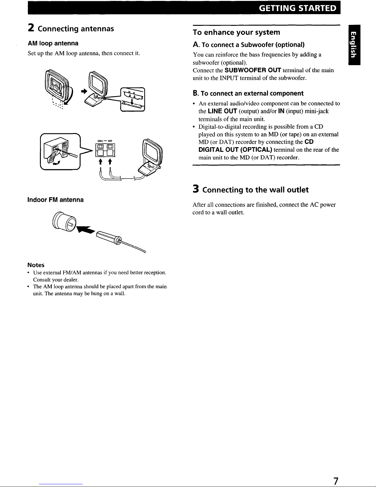
Connecting antennas
To enhance your system
AM loop antenna
Set up the AM loop antenna, then connect it.
A.
To connect a Subwoofer (optional)
You can reinforce the bass frequencies by adding a
subwoofer (optional).
Connect the
SUBWOOFER OUT terminal of the main
unit to the INPUT terminal of the subwoofer.
B.
To connect an external component
l
An external audio/video component can be connected to
the LINE OUT (output) and/or IN (input) mini-jack
terminals of the main unit.
l
Digital-to-digital recording is possible from a CD
played on this system to an MD (or tape) on an external
MD (or DAT) recorder by connecting the CD
DIGITAL OUT (OPTICAL) terminal on the rear of the
main unit to the MD (or DAT) recorder.
3 Connecting to the wall outlet
Indoor FM antenna
After all connections are finished, connect the AC power
cord to a wall outlet.
Notes
l
Use external FM/AM antennas if you need better reception.
Consult your dealer.
l
The AM loop antenna should be placed apart from the main
unit. The antenna may be hung on a wall.
7
, GETTING STARTED
2 Connecting antennas
AM loop antenna
Set up the AM loop antenna, then connect it.
GNO-AM
faa
t t
lb-
Indoor
FM
antenna
Notes
• Use external FM/AM antennasifyou need better reception.
Consult your dealer.
• The AM loop antenna should be placed apart from the main
unit. The antenna may be hung on a wall.
To enhance your system
A.
To connect a Subwoofer (optional)
You can reinforce the bass frequencies by adding a
subwoofer (optional).
Connect the SUBWOOFER OUT terminal
of
the main
unit
to
the INPUT terminalofthe subwoofer.
B.
To connect an external component
• An external audio/video component can be connected to
the LINE OUT (output) and/or
IN
(input) mini-jack
terminals
of
the main unit.
• Digital-to-digital recording is possible from a CD
played on this system
to
an MD (or tape) on an external
MD (or DAT) recorder by connecting the CD
DIGITAL OUT (OPTICAL) terminal on the rear
of
the
main unit to the MD (or DAT) recorder.
3 Connecting
to
the
wall outlet
After
all
connections are finished, connect the AC power
cord to a wall outlet.
7
 Loading...