

Yamaha DVX-700D, NS-PSW700, NS-P700, VR-700 Owner's Manual

G
OWNER’S MANUAL
MODE D’EMPLOI
BEDIENUNGSANLEITUNG
BRUKSANVISNING
MANUALE DI ISTRUZIONI
MANUAL DE INSTRUCCIONES
GEBRUIKSAANWIJZING
DVX-700
(DVR-700 + NS-PSW700 + NS-P700)
DVD HOME THEATER SYSTEM
SYSTEME HOME CINEMA AVEC LECTUER DVD
LASER INFORMATION
INFORMATION LASER
LASERINFORMATIONEN
LASERINFORMATION
INFORMAZIONI SUL LASER
INFORMACIÓN DE LÁSER
LASERINFORMATIE
ИНФОРМАЦИЯ О ЛАЗЕРЕ
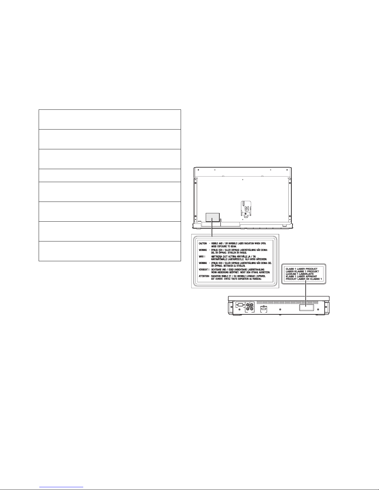
● The name plate is located on the rear panel of the DVD
controller.
● La plaque signalétique se trouve sur le panneau arrière du
lecteur de DVD.
● Das Typenschild befindet sich an der Rückseite des DVDControllers.
● Namnskylten sitter på DVD-enhetens baksida.
● La targhetta dati costruttore è posizionata sul pannello
posteriore del controller DVD.
● La placa de datos está situada en el panel trasero del
controlador de DVD.
● Het naamplaatje bevindt zich op het achterpaneel van de
DVD-receiver.
● Фирменная табличка расположена на задней
панели DVD-контроллера.
Without top cover
Sans couvercle supérieur
Ohne Abdeckung oben
Utan övre skydd
Senza coperchio superiore
Sin cubierta superior
Zonder bovenklep
Без верхней крышки
Caution-i En
English
1 To assure the finest performance, please read this manual
carefully. Keep it in a safe place for future reference.
2 Install this sound system in a well ventilated, cool, dry, clean
place — way from direct sunlight, heat sources, vibration,
dust, moisture, and/or cold. Allow ventilation space of at least
5 cm on the top, left, right, and the back of this unit.
3 Locate this unit away from other electrical appliances, motors,
or transformers to avoid humming sounds.
4 Do not expose this unit to sudden temperature changes from
cold to hot, nor locate this unit in an environment with high
humidity (i.e., a room with a humidifier) to prevent
condensation inside this unit, which may cause an electrical
shock, fire, damage to this unit, and/or personal injury.
5 Avoid installing this unit in a location where foreign objects
may fall onto this unit or where this unit may be exposed to
liquid dripping or splashing. On the top of this unit, do not
place:
– Other components, as they may cause damage and/or
discoloration on the surface of this unit.
– Burning objects (i.e., candles), as they may cause fire,
damage to this unit, and/or personal injury.
– Containers with liquid in them, as they may fall, spilling
the liquid and causing an electrical shock to the user and/
or damage to this unit.
6 Do not cover this unit with a newspaper, tablecloth, curtain,
etc. in order not to obstruct heat radiation. If the temperature
inside this unit rises, it may cause fire, damage to this unit,
and/or personal injury.
7 Do not plug in this unit to a wall outlet until all connections
are complete.
8 Do not operate this unit upside-down. It may overheat,
possibly causing damage.
9 Do not use excessive force on switches, knobs and/or cords.
10 When disconnecting the power cable from the wall outlet,
grasp the plug; do not pull the cable.
11 Do not clean this unit with chemical solvents; this might
damage the finish. Use a clean, dry cloth.
12 Use only the voltage specified on this unit. Using this unit
with a higher voltage than specified is dangerous and may
cause fire, damage to this unit, and/or personal injury.
Yamaha will not be held responsible for any damage resulting
from use of this unit with a voltage other than as specified.
13 To prevent damage by lightning, keep the power cable out and
outdoor antennas disconnected from a wall outlet or the unit
during a lightning storm.
14 Do not attempt to modify or fix this unit. Contact qualified
Yamaha service personnel when any service is needed. The
cabinet should never be opened for any reason.
15
When not planning to use this unit for long periods of time (i.e.,
vacation), disconnect the AC power plug from the wall outlet.
16 Be sure to read the “TROUBLESHOOTING” section on
common operating errors before concluding that this unit is
faulty.
17 Before moving this unit, press STANDBY/ON to set the unit
in standby mode, then disconnect the AC power plug from the
wall outlet.
18 Condensation will form when the surrounding temperature
changes suddenly. Disconnect the power cable from the
outlet, then leave the unit alone.
19 When using the unit for a long time, the unit may become
warm. Turn the power off, then leave the unit alone for
cooling.
20 Install this unit near the AC outlet and where the AC power
plug can be reached easily.
21 The batteries shall not be exposed to excessive heat such as
sunshine, fire or like.
22 Excessive sound pressure from earphones and headphones
can cause hearing loss.
23 When replacing the batteries, be sure to use batteries of the
same type. Danger of explosion may happen if batteries are
incorrectly replaced.
Caution: read this before operating your unit.
This unit is not disconnected from the AC power
source as long as it is connected to the wall outlet,
even if this unit itself is turned off. This state is called
the standby mode. In this state, this unit is designed to
consume a very small quantity of power.
Laser component in this product is capable of emitting
radiation exceeding the limit for Class 1.
WARNING
TO REDUCE THE RISK OF FIRE OR ELECTRIC
SHOCK, DO NOT EXPOSE THIS UNIT TO RAIN
OR MOISTURE.
CAUTION
Danger of explosion if battery is incorrectly replaced.
Replace only with the same or equivalent type.
This product complies with the radio interference
requirements of the European Community.
This product complies with the
requirements of the following directives
and guidelines: 2006/95/EC + 2004/
108/EC
Caution-ii En
Limited Guarantee for European Economic Area (EEA) and Switzerland
Thank you for having chosen a Yamaha product. In the unlikely event that your Yamaha product needs guarantee service, please contact the dealer from
whom it was purchased. If you experience any difficulty, please contact Yamaha representative office in your country. You can find full details on our
website (www.yamaha-hifi.com/
or www.yamaha-uk.com/ for U.K. resident).
The product is guaranteed to be free from defects in workmanship or materials for a period of two years from the date of the original purchase. Yamaha
undertakes, subject to the conditions listed below, to have the faulty product or any part(s) repaired, or replaced at Yamaha’s discretion, without any charge
for parts or labour. Yamaha reserves the right to replace a product with that of a similar kind and/or value and condition, where a model has been
discontinued or is considered uneconomic to repair.
Conditions
1. The original invoice or sales receipt (showing date of purchase, product code and dealer’s name) MUST accompany the defective product, along with a
statement detailing the fault. In the absence of this clear proof of purchase, Yamaha reserves the right to refuse to provide free of charge service and the
product may be returned at the customer’s expense.
2. The product MUST have been purchased from an AUTHORISED Yamaha dealer within the European Economic Area (EEA) or Switzerland.
3. The product must not have been the subject of any modifications or alterations, unless authorised in writing by Yamaha.
4. The following are excluded from this guarantee:
a. Periodic maintenance and repair or replacement of parts due to normal wear and tear.
b. Damage resulting from:
(1) Repairs performed by the customer himself or by an unauthorised third party.
(2) Inadequate packaging or mishandling, when the product is in transit from the customer. Please note that it is the customer’s responsibility to
ensure the product is adequately packaged when returning the product for repair.
(3) Misuse, including but not limited to (a) failure to use the product for its normal purpose or in accordance with Yamaha’s instructions on the proper
use, maintenance and storage, and (b) installation or use of the product in a manner inconsistent with the technical or safety standards in force in
the country where it is used.
(4) Accidents, lightning, water, fire, improper ventilation, battery leakage or any cause beyond Yamaha’s control.
(5) Defects of the system into which this product is incorporated and/or incompatibility with third party products.
(6) Use of a product imported into the EEA and/or Switzerland, not by Yamaha, where that product does not conform to the technical or safety
standards of the country of use and/or to the standard specification of a product sold by Yamaha in the EEA and/or Switzerland.
(7) Non AV (Audio Visual) related products.
(Products subject to “Yamaha AV Guarantee Statement” are defined in our website at www.yamaha-hifi.com/
or www.yamaha-uk.com/ for U.K.
resident.)
5. Where the guarantee differs between the country of purchase and the country of use of the product, the guarantee of the country of use shall apply.
6. Yamaha may not be held responsible for any losses or damages, whether direct, consequential or otherwise, save for the repair or replacement of the
product.
7. Please backup any custom settings or data, as Yamaha may not be held responsible for any alteration or loss to such settings or data.
8. This guarantee does not affect the consumer’s statutory rights under applicable national laws in force or the consumer’s rights against the dealer arising
from their sales/purchase contract.
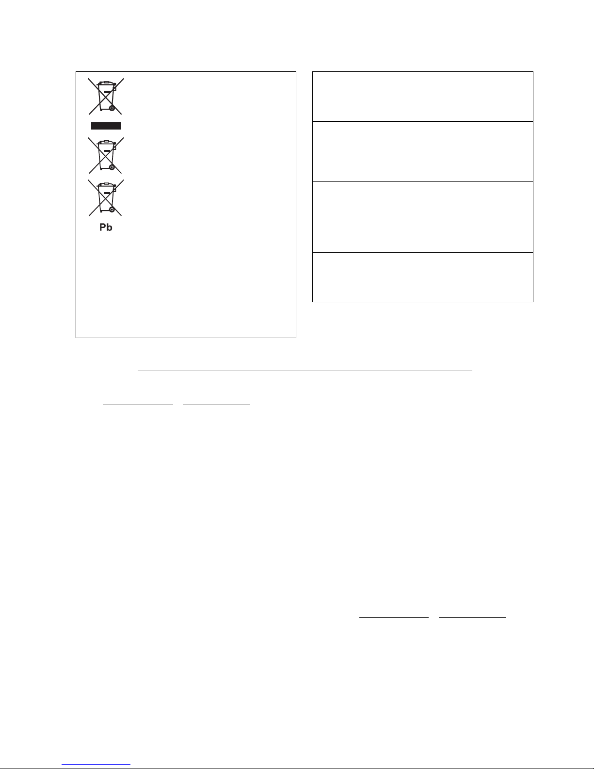
Information for Users on Collection and
Disposal of Old Equipment and used
Batteries
These symbols on the products, packaging, and/or
accompanying documents mean that used electrical and
electronic products and batteries should not be mixed
with general household waste. For proper treatment,
recovery and recycling of old products and used
batteries, please take them to applicable collection
points, in accordance with your national legislation and
the Directives 2002/96/EC and 2006/66/EC.
By disposing of these products and batteries correctly,
you will help to save valuable resources and prevent any
potential negative effects on human health and the
environment which could otherwise arise from
inappropriate waste handling.
For more information about collection and recycling of
old products and batteries, please contact your local
municipality, your waste disposal service or the point of
sale where you purchased the items.
[Information on Disposal in other Countries outside the European
Union]
These symbols are only valid in the European Union. If you wish to discard
these items, please contact your local authorities or dealer and ask for the
correct method of disposal.
Note for the battery symbol (bottom two symbol examples):
This symbol might be used in combination with a chemical symbol. In this
case it complies with the requirement set by the Directive for the chemical
involved.
LASER SAFETY
This unit employs a laser. Due to possible eye injury, only a
qualified service person should remove the cover or attempt
to service this device.
DANGER
This unit emits visible laser radiation when open.
Avoid direct eye exposure to beam. When this unit is plugged
into a wall outlet, do not place your eyes close to the opening
of the disc loader and other openings or look inside.
LASER
Type Semiconductor laser ALGaInP
Wave length 655nm (DVD)
790nm (VCD/CD)
Output Power 5/7mW (DVD/VCD,CD)
Beam divergence 20degrees
CAUTION
Use of controls or adjustments or performance of procedures
other than those specified herein may result in hazardous
radiation exposure.

1 En
1
2
3
4
5
6
7
8
English
INTRODUCTION ......................................... 2
Main unit ............................................................. 4
Supplied accessories............................................ 4
FUNCTIONAL OVERVIEW ......................... 5
Front panel (DVR-700) ....................................... 5
Rear panel (DVR-700) ........................................ 6
Front panel display (DVR-700) ........................... 7
Rear panel (NS-PSW700).................................... 8
Remote control .................................................... 9
CONNECTIONS ........................................ 11
Roles and layout of the speakers ....................... 11
Placing the speakers using the stands ................ 12
Placing the speakers on a wall ........................... 12
SYSTEM CONNECTIONS......................... 14
Connecting the speakers .................................... 14
Connecting the DVD controller and the subwoofer/
system control................................................ 16
OTHER CONNECTIONS........................... 17
Connecting a TV................................................ 17
Connecting an HDMI component ..................... 18
Connecting the FM antenna............................... 18
Connecting external AV components................ 19
Connecting the power cable .............................. 20
GETTING STARTED................................. 21
Inserting batteries into the remote control ......... 21
Using the remote control ................................... 21
Turn on the system ............................................ 22
Setting the video input/output ........................... 23
Setting language preferences............................. 25
DISC OPERATION.................................... 26
Playing discs ...................................................... 26
Basic playback controls ..................................... 27
Ejecting a disc.................................................... 28
Using the disc menu (DVD only) ...................... 28
Playback control (PBC) (Video CD only)......... 28
Changing soundtrack language.......................... 28
Changing subtitle language ............................... 29
Resuming playback from the last stopped point 29
Viewing from another angle .............................. 29
Displaying disc information .............................. 29
Zooming in ........................................................ 29
Advanced operation ........................................... 30
Disc navigator.................................................... 32
PLAYING OTHER DISCS ......................... 33
To play back audio files .................................... 33
To start a slide show of JPEG files.................... 34
Selecting a file to play back............................... 34
Using a USB device........................................... 35
DVD SETUP MENU OPTIONS................. 36
Menu overview................................................... 36
VIDEO ADJUST MENU ............................ 37
INITIAL SETTINGS MENU....................... 38
Video Output ...................................................... 38
Language ............................................................ 40
Display ............................................................... 41
Options ............................................................... 41
AIR SURROUND XTREME ...................... 43
What is AIR SURROUND XTREME? ............. 43
Listening to surround mode of AIR SURROUND
XTREME ....................................................... 43
Shifting the optimum listening area from side to
side ................................................................. 44
Selecting the optimum distance between the
speakers .......................................................... 44
Checking the virtual surround effect.................. 45
Using extended stereo mode .............................. 45
Setting compressed music enhancer................... 45
LISTENING TO FM BROADCASTS......... 46
Basic tuning operation........................................ 46
Using station preset feature ................................ 47
Recalling the preset stations............................... 49
Receiving Radio Data System stations
(Europe and Russia models only) .................. 49
USING OPTIONAL EQUIPMENT............. 52
Using iPod™ ...................................................... 52
Using Bluetooth™ components ......................... 53
USEFUL OPERATION.............................. 55
Adjusting the audio delay................................... 55
Listening at low volume (night listening mode) 55
Adjusting the audio balance for the playback.... 56
Changing the brightness of the front panel
display ............................................................ 56
Setting the sleep timer ........................................ 57
System menu ...................................................... 57
Setting the preset code ....................................... 58
TROUBLESHOOTING.............................. 59
GLOSSARY .............................................. 64
SPECIFICATIONS .................................... 66
INDEX ....................................................... 67
LIST OF PRESET CODES................................... i
LIST OF COUNTRY CODES ........................... iii
LIST OF LANGUAGE CODES ......................... iv
CONTENTS
1. INTRODUCTION
2. CONNECTIONS
3. PREPARATION
4. BASIC OPERATIONS
5. DVD SETUP MENU
6. OTHER FUNCTIONS
7. USEFUL OPERATION
8. ADDITIONAL INFORMATION
APPENDIX
2 En
INTRODUCTION
Thank you for purchasing this unit. This Owner’s Manual
explains the basic operation of this unit.
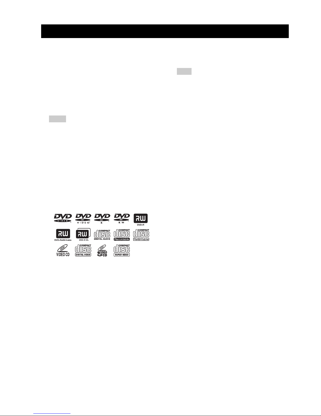
Notes about discs
– This DVD controller is designed for use with the
following discs.
Notes
– DVD-R/-RW/-R DL and DVD+R/+RW/+R DL
discs recorded in DVD-Video compatible format.
– DVD-R/-RW/-R DL discs recorded in VR format
(compatible with CPRM).
– CD-R/RW, DVD-R/-RW/-R DL and DVD+R/
+RW/+R DL cannot be played unless finalized.
– Multi-session discs are not supported.
– Some discs recorded on PC cannot be played
depending on the settings of the application
software.
– Discs recorded on PC in packet write format are
not compatible with this DVD controller.
– This unit is not compatible with 8-cm discs.
This controller can play the following formatted files
recorded on CD-R/RW, DVD-R/-RW, DVD+R/+RW and
USB device.
Compressed audio file
– MPEG1 audio layer3 (MP3)
– Windows Media Audio (WMA)
– MPEG-4 AAC
Still image file
–JPEG
– FUJICOLOR CD
– KODAK Picture CD
Movie file
(except files saved on USB devices)
–WMV
–DivX
®
Ultra
– Official DivX
®
Ultra Certified product.
– Plays all versions of DivX
®
video (including
DivX
®
6) with enhanced playback of DivX®
media files and the DivX
®
Media Format.
Hint
Refer to “DISC OPERATION” on page 26 for details.
Cleaning discs
– When a disc becomes dirty, clean it with a cleaning
cloth. Wipe the disc from the center out. Do not
wipe in a circular motion.
– Do not use solvents such as benzine, thinner,
commercially available cleaners, or antistatic spray
intended for analog records.
Avoid high temperatures, moisture, water
and dust
– Do not expose the system, batteries or discs to
humidity, rain, sand or excessive heat (caused by
heating equipment or direct sunlight).
Avoid condensation problem
– The lens may cloud over when the controller is
suddenly moved from cold to warm surroundings,
making it impossible to play a disc. Leave the
controller in the warm environment until the
moisture evaporates.
Disc care
– Write only on the printed side of a CD-R/RW,
DVD-R/-RW/-R DL, DVD+R/+RW/+R DL and
only with a soft felt tipped pen.
– Handle the disc by its edge; do not touch the
surface.
Lens care
– Basically, lens cleaning is not necessary.
– Do not use lens cleaner because it may cause
malfunction.
Cabinet care
– Use a soft cloth slightly moistened with a mild
detergent solution. Do not use a solution containing
alcohol, spirits, ammonia, or abrasives.
Choosing a suitable location
– Place the controller on a flat, hard, and stable
surface.
INTRODUCTION
DVD disc: DVD-Video, DVD-R/-RW/-R
DL, DVD+R/+RW/+R DL
Compact Disc: Audio CD, CD-R, CD-RW,
Video CD, Super Video CD
3 En
INTRODUCTION
English
INTRODUCTION
1
Region codes
The unit is designed to support the Region Management
System. Check the region code number on the disc
package. If the number does not match the unit’s region
number (Refer to the table below or the back of the unit),
the unit may be unable to play the disc.
Features
Destination
Region code
of DVR-700
Playable discs
U.S.A., and
Canada model
Europe
model
Asia and Taiwan
models
Australia
model
Russia
model
1 1
ALL
2 2
ALL
3 3
ALL
4 4
ALL
5 5
ALL
Manufactured under license from Dolby
Laboratories. “Dolby”, “Pro Logic”,
“MLP Lossless” and the double-D symbol
are trademarks of Dolby Laboratories.
“DTS” and “DTS Digital Surround” are
registered trademarks of DTS, Inc.
DivX
®
, DivX® Ultra Certified, and
associated logos are trademarks of
DivX
®
, Inc. and are used under license.
HDMI, the HDMI logo and High
Definition Multimedia Interface are
trademarks or registered trademarks of
HDMI Licensing LLC.
“Apple”, “iPod”, and “iTunes” are trademarks of Apple Inc.,
registered in the U.S. and other countries.
Bluetooth is a registered trademark of Bluetooth SIG and is used
by Yamaha in accordance with a license agreement.
Windows Media is either a registered trademark or trademark of
Microsoft Corporation in the United States and/or other countries.
This product incorporates copyright protection
technology that is protected by U.S. patents and other
intellectual property rights. Use of this copyright
protection technology must be authorized by
Macrovision, and is intended for home and other
limited viewing uses only unless otherwise authorized
by Macrovision. Reverse engineering or disassembly
is prohibited.
This system employs new technologies and algorithms
that make it possible to achieve 7-channel surround
sound with only two speakers, and without using wall
reflections.
4 En
INTRODUCTION
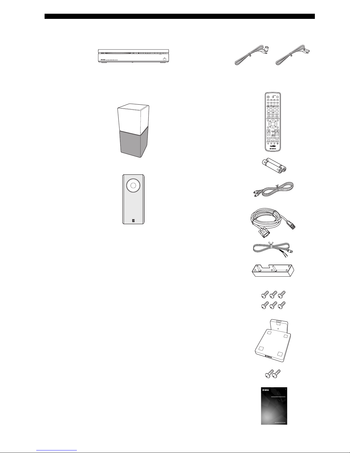
■ Main unit ■ Supplied accessories
Speaker (L/R)
(NS-P700)
Subwoofer/system control
(NS-PSW700)
DVD controller
(DVR-700)
Speaker package
SLEEP
NIGHT
ENHANCER
AUDIO DELAY
AUDIO
PTY SEEK
PLAY MODE
INFO.
A-E A-E
MENU
TOP MENU
SETUP RETURN
CODE SET
ANGLE
CLEAR
FREQ / TEXT
MEMORY
START
MODE
SUBTITLE
AUTO
/
MANUAL
PRESET
ENTER
TV
/
STB
TV VOL
VOLUME
TUNER MUTE
TV INPUT
DVD
/
USB INPUT 1-4
POSITION
AREA SOUND TEST
DOCK
CH
PRESET
/
TUNE
STEREO
ON SCREEN
ZOOM
ON OFF
BLUETOOTH
DISP. MODE
GAMESPORTS
MUSIC
FUNC.
WP87020DVX-700
TV STB
POWER
STANDBY
/
ON
10KEY
MOVIE
G
OWNER’S MANUAL
MODE D’EMPLOI
BEDIENUNGSANLEITUNG
BRUKSANVISNING
MANUALE DI ISTRUZIONI
MANUAL DE INSTRUCCIONES
GEBRUIKSAANWIJZING
DVX-700
(DVR-700 + NS-PA700)
DVD HOME THEATER SYSTEM
SYSTEME HOME CINEMA AVEC LECTUER DVD
Remote control
Battery x 2
(AA, R6, UM-3)
System control cable (4 m)
Speaker cable x 2 (4 m)
Video pin cable (1.5 m)
Indoor FM antenna
Cover
(For NS-PSW700)
Screw x 6
(for cover 3 x 6 mm)
Stand x 2
(For NS-P700)
Screw x 2
(for stand 4 x 10 mm)
Owner’s Manual
(U.S.A., Canada,
Asia and Taiwan
models)
(Europe, Russia
and Australia
models)
5 En
English
INTRODUCTION
1
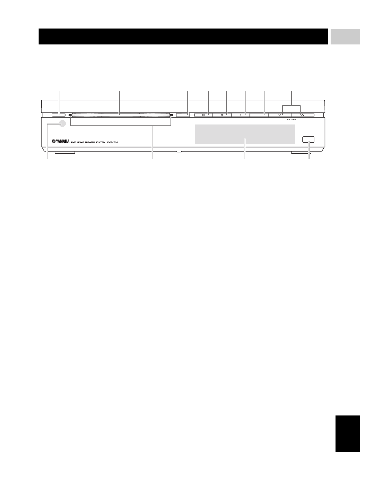
■ Front panel (DVR-700)
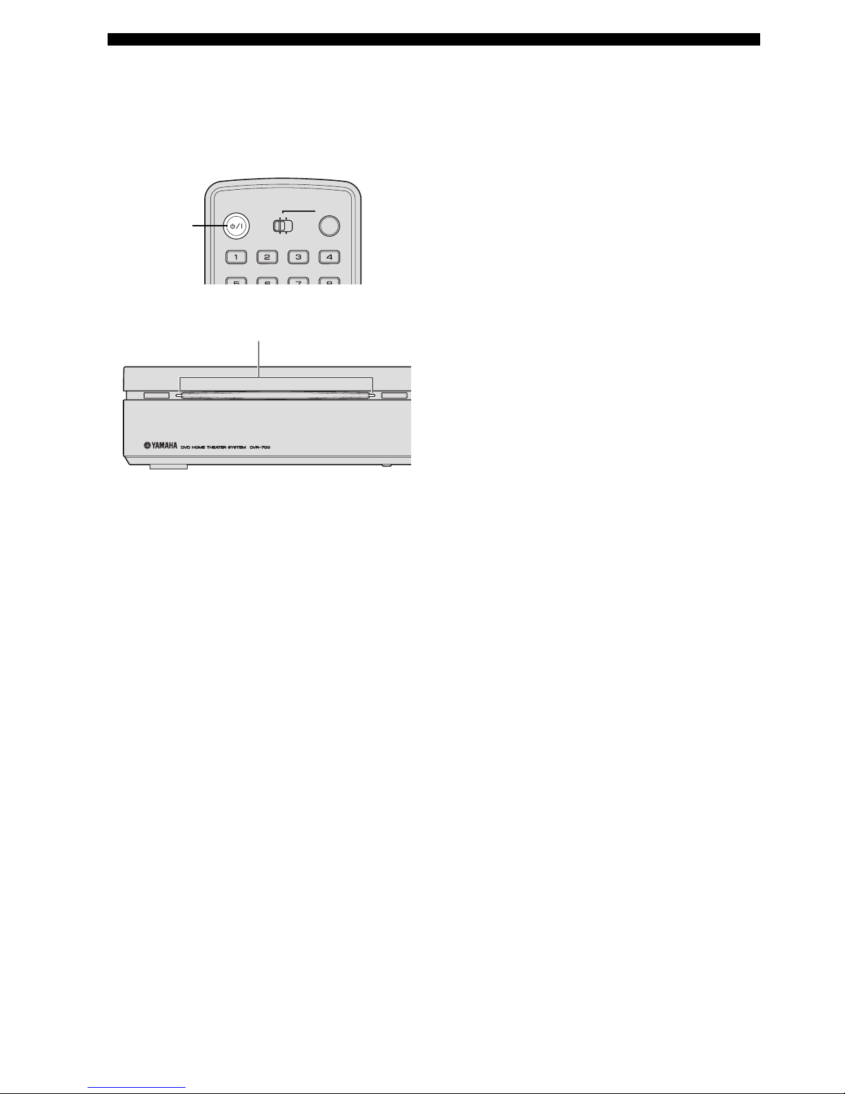
1 STANDBY/ON
Turns on the system, or sets it to standby mode
(Page 22).
2 Disc loading slot
Insert a disc to be played.
3 EJECT
Ejects a disc in the DVD controller.
4 s
Stops playback.
5 e
Pauses playback.
6 h
Starts playback.
7 INPUT
Selects an input source by pressing repeatedly.
8 VOLUME u / d
Adjusts the volume level.
9 Remote control sensor
Point the remote control towards this sensor.
0 Power indicator
Lights up when system is on.
A Front panel display
Shows information about the operational status of the
unit.
B USB terminal
Connect to the USB connector of your USB device
(Page 35).
FUNCTIONAL OVERVIEW
STANDBY / ON
EJECT INPUT
USB
12 345678
B09A
6 En
FUNCTIONAL OVERVIEW
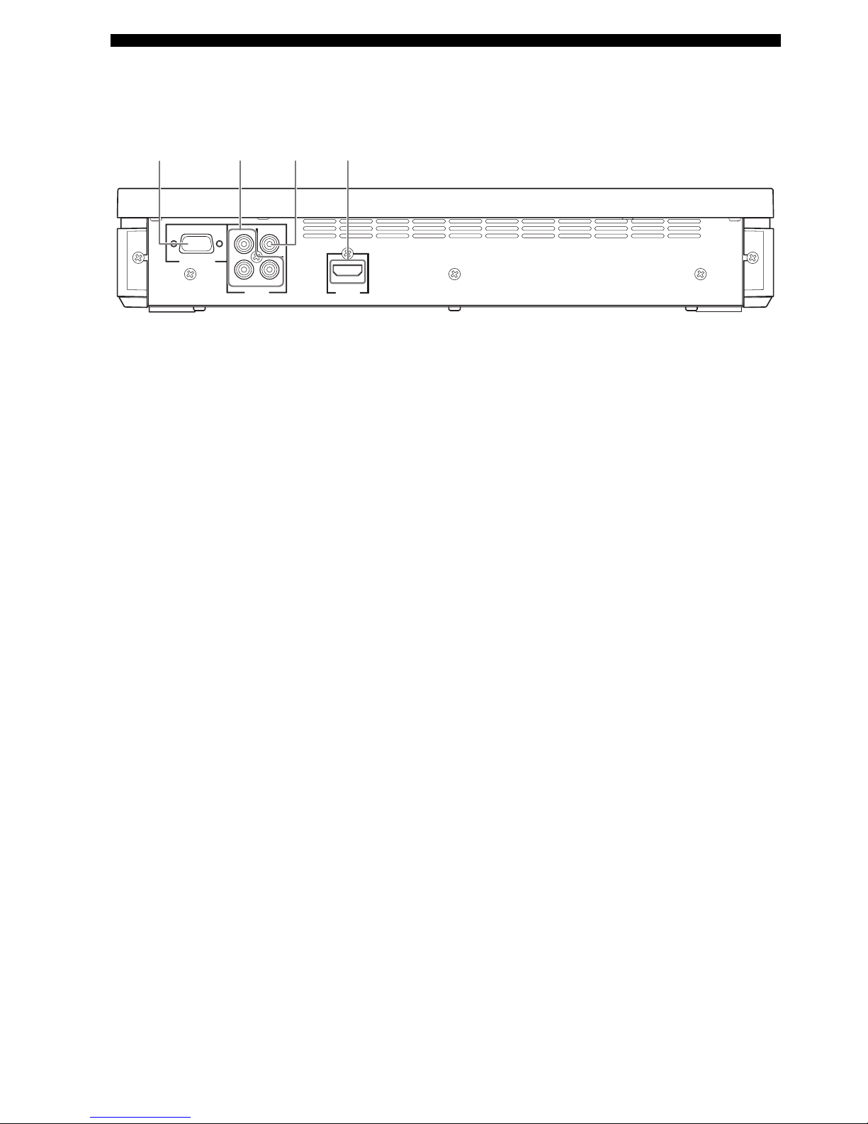
■ Rear panel (DVR-700)
1 SYSTEM CONNECTOR terminal
Connect to the subwoofer/system control (Page 16).
2 COMPONENT VIDEO OUTPUT jacks
Connect to the Y PB/CB PR/CR jacks on your TV
(Page 17).
3 VIDEO OUTPUT jack
Connect to the video (composite) jack on your TV
(Page 17).
4 HDMI OUTPUT terminal
Connect to the HDMI input terminal on your TV
(Page 18).
SYSTEM
CONNECTOR
NS-PSW700
VIDEO
COMPONENT
Y
P
B
PR
VIDEO
OUTPUT
HDMI
OUTPUT
1234
7 En
FUNCTIONAL OVERVIEW
English
INTRODUCTION
1
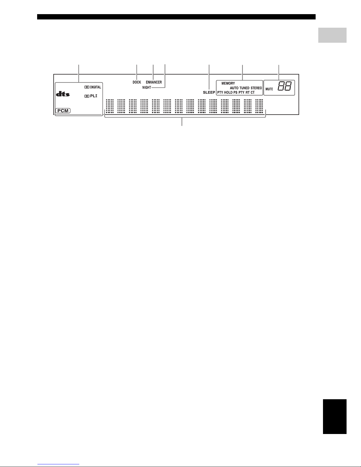
■ Front panel display (DVR-700)
1 Decoder indicators
The respective indicator lights up when any of the
decoders of the system is functioning.
2 DOCK indicator
– Lights up when the system is receiving a signal
from an iPod stationed in the Yamaha iPod
universal dock (such as YDS-10 or YDS-11, sold
separately) connected to the DOCK terminal of the
subwoofer/system control (Page 20).
– Lights up while the Yamaha Bluetooth wireless
audio receiver (such as YBA-10, sold separately) is
connected to the Bluetooth component (Page 53).
– Flashes while the connected Yamaha Bluetooth
wireless audio receiver (such as YBA-10, sold
separately) and the Bluetooth component are
pairing or while the Yamaha Bluetooth wireless
audio receiver is searching for the Bluetooth
component (Page 53).
3 ENHANCER indicator
Lights up when compressed music enhancer mode is
selected (Page 45).
4 NIGHT indicator
Lights up when you select night listening mode
(Page 55).
5 SLEEP indicator
Lights up when sleep mode is on (Page 57).
6 Tuner indicators (AUTO/TUNED/STEREO/
MEMORY/PTY HOLD/PS/PTY/RT/CT)
AUTO indicator
Lights up when the system is in automatic tuning
mode (Page 46).
TUNED indicator
Lights up when the system is receiving a station
(Page 46).
STEREO indicator
Lights up when the system is receiving a strong signal
from an FM stereo broadcast in automatic tuning
mode (Page 46).
MEMORY indicator
Flashes to show a station can be stored (Page 47).
PTY HOLD indicator
Lights up while the system is in PTY SEEK mode.
PS/PTY/RT/CT indicator
Lights up according to the available Radio Data
System information (Page 49).
7 Multi information display
Shows the information, such as playing time and
selected input source. When you adjust or change a
setting, the value is displayed.
8 MUTE indicator/VOLUME indicator
– Flashes while the mute function is activated.
– Indicates the current volume level.
12345
7
68
8 En
FUNCTIONAL OVERVIEW
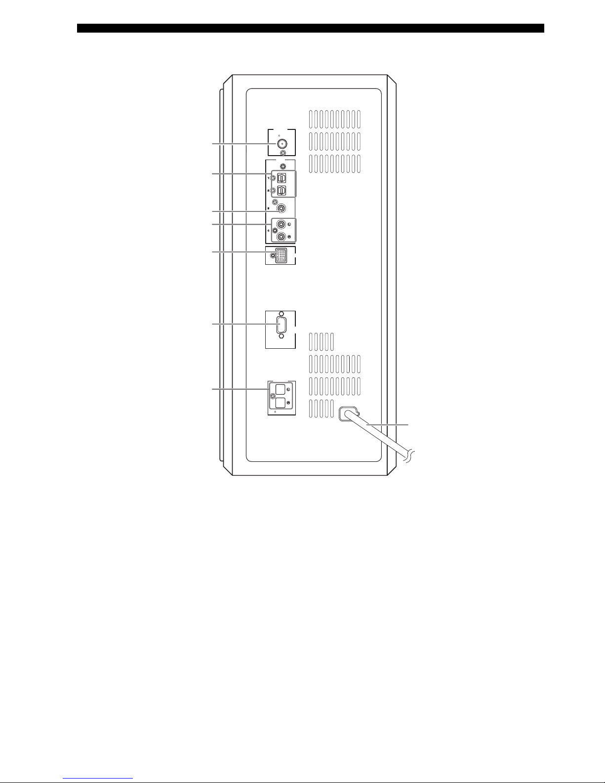
■ Rear panel (NS-PSW700)
1 ANTENNA terminal
Connect the FM antenna.
2 INPUT 1/2 OPTICAL jacks
Connect to the DIGITAL OUT jack (Optical Type) on
your digital audio component.
These input jacks support PCM, Dolby Digital, and
DTS bitstream.
3 INPUT 3 COAXIAL jack
Connect to the DIGITAL OUT jack (Coaxial Type) on
your digital audio component.
This input jack support PCM, Dolby Digital, and DTS
bitstream.
4 INPUT 4 ANALOG jacks
Connect to the ANALOG OUT jack if the component
does not have DIGITAL OUT jacks.
5 DOCK terminal
Connect the Yamaha iPod Universal Dock (such as
YDS-10 or YDS-11, sold separately) or Yamaha
Bluetooth wireless audio receiver (such as YBA-10,
sold separately) (Page 20).
6 SYSTEM CONNECTOR terminal
Connect to the DVD controller.
7 SPEAKER terminals
Connect to the speakers.
8 Power cable
Connect to a standard AC outlet.
FM
75
UNBAL
.
ANTENNA
INPUT
DOCK
SYSTEM
CONNECTOR
DVR-700
SPEAKERS
MAINS
SPEAKER
IMPEDANCE
:
6 MIN.
OPTICAL
OPTICAL
COAXIAL
ANALOG
1
2
3
4
5
6
7
8
9 En
FUNCTIONAL OVERVIEW
English
INTRODUCTION
1
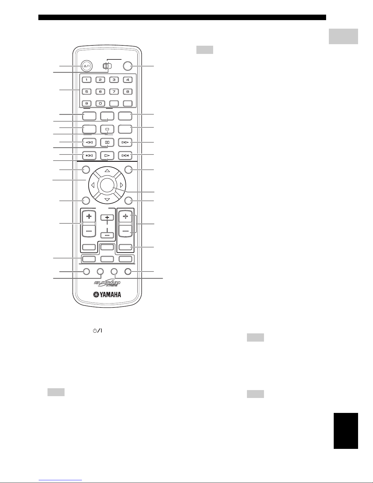
■ Remote control
1 STANDBY/ON ( )
Turns on the this system, or sets it to the standby
mode.
2 FUNC./10KEY
Switches the operation of the Function/Numeric
keypad keys. Also, the preset code to operate TV or
STB.
Hint
Using the remote control, you can operate two kinds
of peripheral devices such as TV and satellite tuner.
When operating them, you need to set the preset codes
depending on the components. Refer to “Setting the
preset code” on page 58.
3 POWER
Turns on the TV.
Note
To operate your TV with the remote control, you need
to set the preset code. Refer to “Setting the preset
code” on page 58.
4 Function / Numeric keypad 0-9
Operates some functions, such as AIR SURROUND
XTREME, and enters track numbers or other
numbers.
The available operation will be changed depending on
the FUNC./10KEY position.
SLEEP
NIGHT
ENHANCER
AUDIO DELAY
AUDIO
PTY SEEK
PLAY MODE
INFO.
A-E A-E
MENU
TOP MENU
SETUP RETURN
CODE SET
ANGLE
CLEAR
FREQ / TEXT
MEMORY
START
MODE
SUBTITLE
AUTO/
MANUAL
PRESET
ENTER
TV
/
STB
TV VOL
VOLUME
TUNER MUTE
TV INPUT
DVD
/
USB INPUT 1-4
POSITION
AREA SOUND TEST
DOCK
CH
PRESET/ TUNE
STEREO
ON SCREEN
ZOOM
ON OFF
BLUETOOTH
DISP. MODE
GAMESPORTS
MUSIC
FUNC.
WP87020DVX-700
TV STB
POWER
STANDBY
/
ON
10KEY
MOVIE
1
5
8
A
D
G
K
Q
M
I
9
B
R
P
E
6
2
4
3
7
0
C
F
H
L
O
t
S
N
J
FUNC./10KEY: FUNC. side
MOVIE
MUSIC
SPORTS
GAME
Select surround mode.
STEREO – Turns extended stereo mode
on and off alternately
(Page 45).
– Turns surround mode off
(Page 43).
ENHANCER Turns compressed music
enhancer mode on and off
alternately (Page 45).
NIGHT Turns night listening mode on
and off alternately (Page 55).
SLEEP Sets the sleep timer (Page 57).
DISP. MODE Changes the brightness of the
front panel display (Page 56).
AUDIO DELAY Delays the output sound to
synchronize it with the video
image (Page 55).
ZOOM Enlarges the pictures while
playing DVD.
Hint
This button can be used
regardless of the FUNC./10KEY
position.
ON SCREEN Displays the disc information on
the TV display.
Hint
This button can be used
regardless of the FUNC./10KEY
position.
FUNC./10KEY: 10KEY side
Enters numeric characters using 0 to 9 buttons.

10 En
FUNCTIONAL OVERVIEW
5 AUDIO
Selects an audio language for the DVD that is playing
(if available).
6 SUBTITLE
Selects a subtitle language for the DVD that is playing
(if available).
7 ANGLE
Selects a camera angle for the DVD that is playing (if
available).
8 PLAY MODE
Displays the Play Mode menu.
9 s
Stops playback.
0 CLEAR
Erases the registered track/chapter order.
A w (PTY SEEK MODE)
Rewinds the disc.
FM: sets the system to the PTY SEEK mode.
B e (PTY SEEK START)
Pauses playback.
FM: starts searching for a Radio Data System station.
C f (FREQ/TEXT)
Fast-forwards the disc.
FM: switches the information display when receiving
Radio Data System.
D b (PRESET/TUNE)
Selects the previous track or chapter.
FM: switches how to select the radio station (preset or
radio frequency) (Page 49).
E h (AUTO/MANUAL)
Starts playback.
FM: selects auto/manual tuning (Page 46).
F a (MEMORY)
Selects the next track or chapter.
FM: registers the radio frequency.
G TOP MENU (INFO.)
Displays the top-level disc menu.
iPod: switches operation mode of the iPod.
H MENU
Displays the disc contents menu.
I Cursors ( / / / )
Selects items or changes values in the menu screen.
– Tuning the FM station.
– Controlling an iPod.
– Changing the settings.
J ENTER
Confirms a selection.
K SETUP
Displays the DVD setup menu.
L RETURN (CODE SET)
– Returns to the previous screen when DVD setup
menu is displayed.
– Use to set the preset code. Refer to “Setting the
preset code” on page 58.
M TV/STB control buttons
TV VOL +/–
Adjusts the TV volume level.
CH +/–
Select the TV channel.
TV INPUT
Selects the TV input.
Note
To operate your TV with the remote control, you need
to set the preset code. Refer to “Setting the preset
code” on page 58.
You can select TV or STB by switching FUNC./
10KEY.
N VOLUME +/–
Adjusts the volume level of DVX-700.
O MUTE
Mutes the volume of DVX-700. Press the button again
to mute OFF.
P Input selection buttons
DVD/USB
Switches the input source to DVD or USB. Each time
you press the button, the input source changes in
sequence.
TUNER
Switches the input source to FM.
INPUT 1-4
Switches the input source to the external input. Each
time you press the button, the input source changes in
sequence from input 1 to input 4.
DOCK
Switches the input source to DOCK.
Selects iPod or Bluetooth as the input source
depending on the option connected to the Dock
terminal.
Q POSITION
Shifts the optimum listening area according to your
listening position (Page 44).
R AREA
Sets the distance between speakers for the best
surround effect (Page 44).
S SOUND
Adjusts the volume balance for the virtual speaker and
subwoofer (Page 56).
T TEST
Outputs the test tone (Page 45).
11 En
English
CONNECTIONS
2
CONNECTIONS
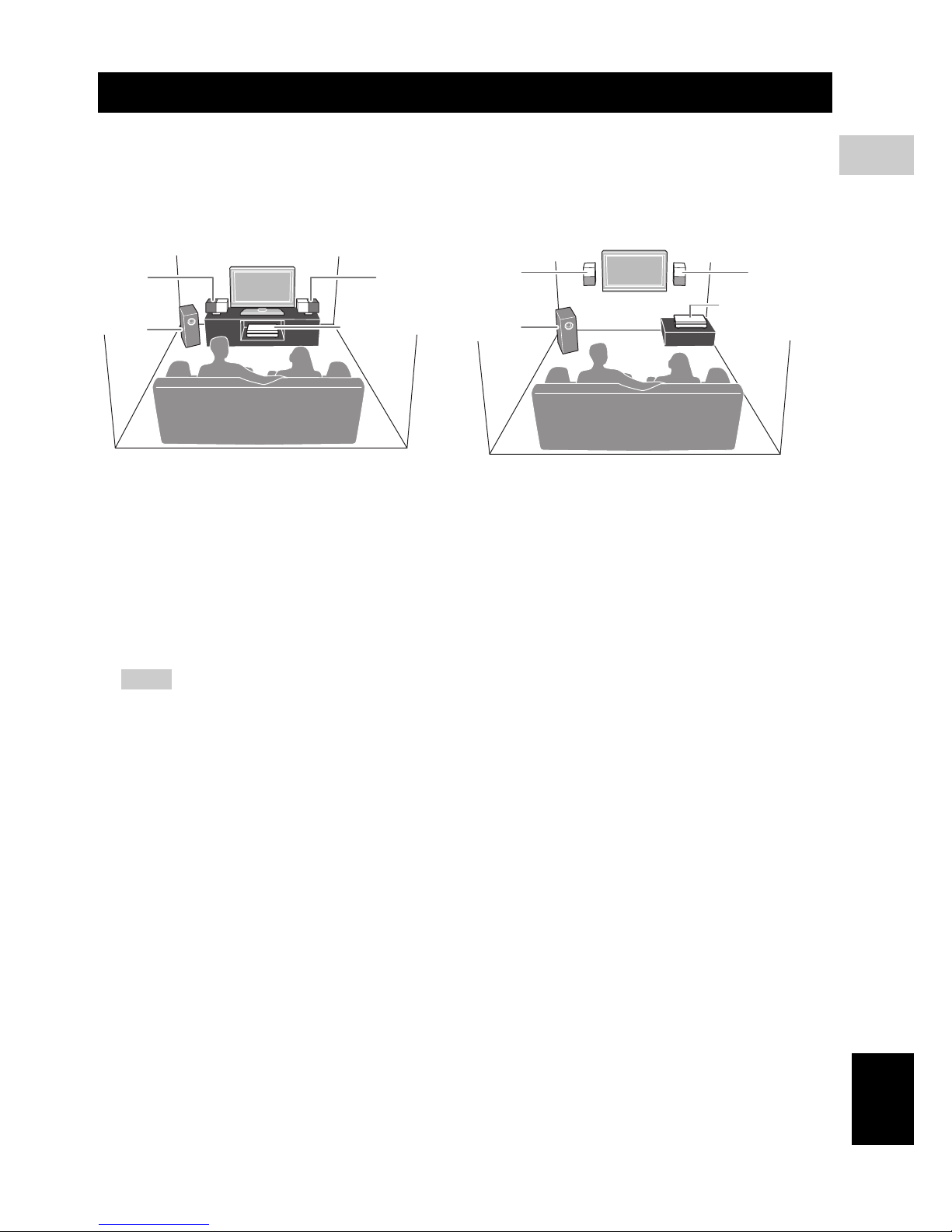
■ Roles and layout of the speakers
To enjoy quality sounds, you need to place the speakers in their appropriate positions and install them correctly.
The following shows the recommended layout of the speakers.
1 Speaker (L, R)
Produces front channel (stereo) sounds. Also produces virtual center channel sounds (dialogue, etc.) and virtual
surround channel sounds effectively using the Yamaha front surround system.
Place the left and right speakers at equal distances away from the listening position so that you can produce high
quality surround sound. You can install the speakers on a rack using the stands or on a wall.
2 Subwoofer/system control
The subwoofer produces bass sounds and LFE sounds contained in Dolby Digital or DTS. Place the subwoofer in the
front of the listening position. Turn it slightly toward the center of the room to reduce wall reflections.
Notes
– To avoid magnetic interference, do not position the speakers too close to your TV.
– Allow adequate ventilation around the DVD controller and subwoofer/system control.
– Bass sounds produced by the subwoofer may be heard differently depending on the listening position and
subwoofer location.
To enjoy desired sounds, try to change the location of the subwoofer according to the listening position.
– You can adjust the surround effect by arranging the position of the speakers (Page 46).
CONNECTIONS
When placing the speakers on a rack When placing the speakers on a wall
11
2
DVD controller
11
2
DVD controller
CONNECTIONS
12 En
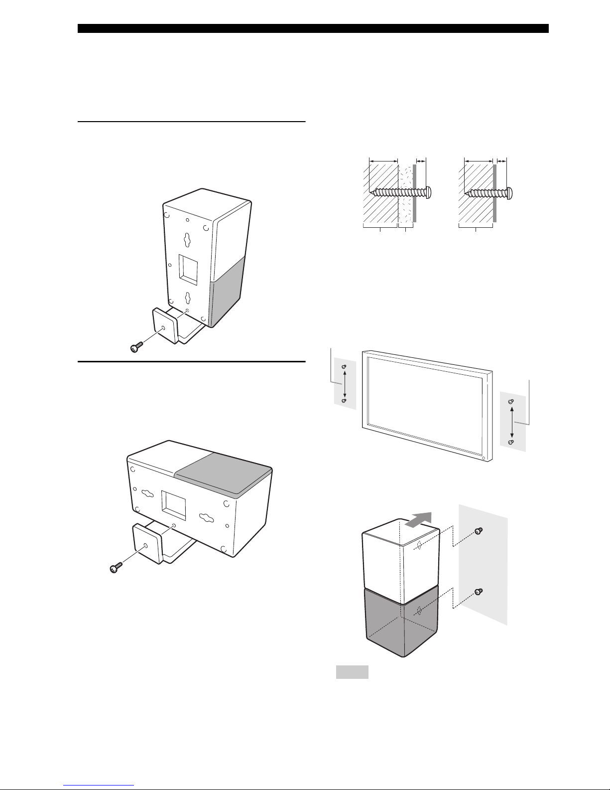
■ Placing the speakers using the
stands
You can place the speakers in an upright position or a
horizontal position. Put the speakers on the stands and
secure them with the screws.
When placing the speaker in an
upright position
Place the speaker on the stand vertically, and then secure it
with the screw as shown in the illustration.
When placing the speakers in a
horizontal position
Put the speaker on the stand so that the black side of the
speaker becomes outside, and then secure it with the screw
as shown in the illustration.
■ Placing the speakers on a wall
Put the speakers on a wall using commercially available
screws. Refer to the illustration below for the screw size.
1 When placing the speakers on a wall, remove the
stands.
2 Install screws on a wall as shown in the illustration.
The distance between the screws: 126 mm for both
sides
3 Insert the screws into the holes on the back of the
speaker.
Notes
– To attach the speaker to a wall with screws, the
wall must be firm. If not you may cause the speaker
to fall.
Tapping screw (Available at the hardware store)
Dia.4 mm (1/8")
Installing on a plaster wall.
Installing on a firm wall.
Min 20 mm
(3/4")
5 mm
(1/4")
Min 20 mm
(3/4")
5 mm
(1/4")
PlasterPillar
or lumber
Pillar
or lumber
126 mm (5")
126 mm (5")

CONNECTIONS
13 En
English
CONNECTIONS
2
– Use commercially available screws that can
support the weight of the installation.
– Make sure you use specified screws to attach the
speakers to a wall. Using clamps other than
specified screws, such as short screws, nails, or
two-sided tape, may cause the speaker to fall.
– After attaching the speakers, check that the
speakers are installed securely. Yamaha will bear
no responsibility for any accidents caused by
improper installations.
14 En
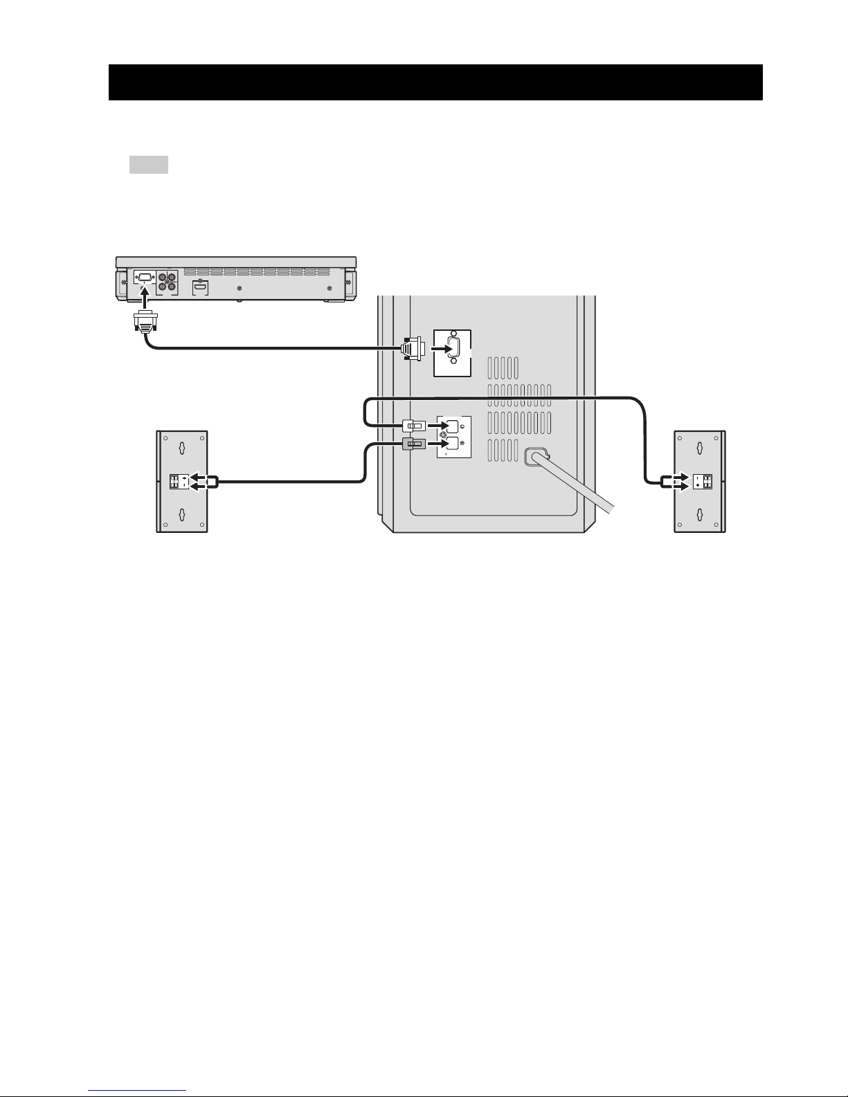
■ Connecting the speakers
Note
Do not connect the power cable of the subwoofer/system control into an AC outlet until all cable connections are
completed.
SYSTEM CONNECTIONS
VIDEO
COMPONENT
PR
VIDEO
OUTPUT
HDMI
OUTPUT
Y
P
B
SYSTEM
CONNECTOR
NS-PSW700
MAINS
SYSTEM
CONNECTOR
DVR-700
SPEAKERS
SPEAKER
IMPEDANCE
:
6 MIN.
Speaker (R)
Subwoofer/system control
DVD controller
Speaker (L)
SYSTEM CONNECTIONS
15 En
English
CONNECTIONS
2
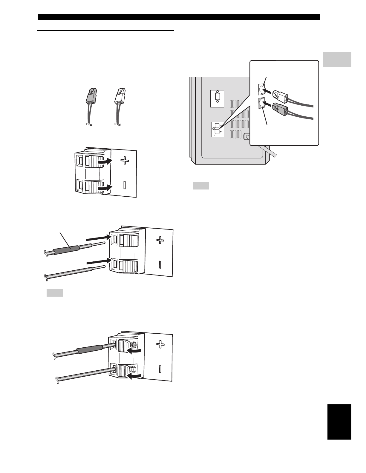
Connecting the speakers and
subwoofer/system control
Connecting the speakers
Confirm the plug colors of the speaker cables.
– Speaker cable with white plug: for speaker (L)
– Speaker cable with red plug: for speaker (R)
1 Push down the knob of the speaker terminal.
2 Insert the stripped speaker cable into the hole on the
speaker terminal.
Note
Connect the cable with red tube to the positive
terminal, and the other cable to the negative terminal.
3 Release the knob of the speaker terminal.
Connecting the subwoofer/system control
1 Insert the speaker cable plug until you hear a click
sound.
Note
Make sure that the cable plugs are connected to the
subwoofer/system control terminals of the same color.
2 Use the same procedure to connect the other speaker
cable.
for speaker (R):
Red plug
for speaker (L):
White plug
Red tube
MAINS
SYSTEM
CONNECTOR
DVR-700
SPEAKERS
SPEAKER
IMPEDANCE
:
6 MIN.
from speaker (L)
from speaker (R)
SYSTEM CONNECTIONS
16 En
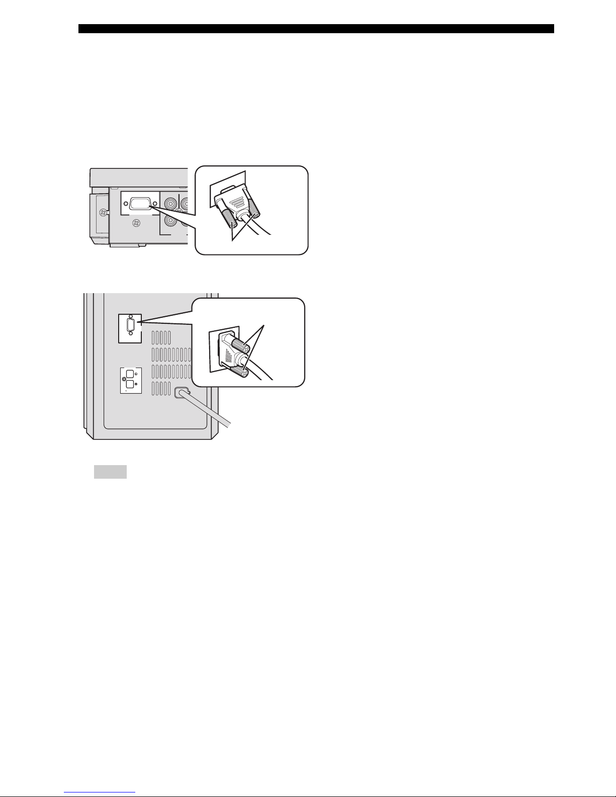
■ Connecting the DVD controller
and the subwoofer/system
control
Connect the SYSTEM CONNECTOR terminal at the rear
of the subwoofer/system control to the SYSTEM
CONNECTOR terminal at the rear of the DVD controller
using the system control cable.
Notes
– Make sure that the system control cable is correctly
connected. Improper connections may damage the
system due to a short-circuit.
– To prevent unwanted noise, do not place the
subwoofer too close to the DVD controller, AC
power adaptor, TV or other sources of radiation.
– Do not insert the Power cable to an AC outlet until
all connections are completed.
MAINS
SYSTEM
CONNECTOR
DVR-700
SPEAKERS
SPEAKER
IMPEDANCE
:
6 MIN.
VID
E
COMPONENT
VIDEO
OUTPUT
Y
P
B
SYSTEM
CONNECTOR
NS-PSW700
NS-PSW700
SYSTEM
CONNECTOR
DV
Tighten the screws.
Tighten the screws.
17 En
English
CONNECTIONS
2
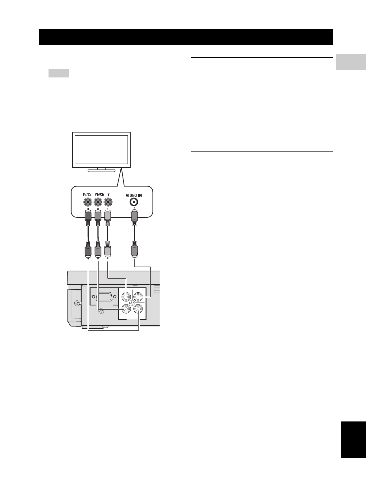
■ Connecting a TV
Notes
– You only need to make one video connection from
the following options (A or B), depending on the
capabilities of your TV.
– Do not connect the power cables until all cable
connections are completed.
COMPONENT VIDEO OUTPUT jacks
<A>
Use the component video cables (Green/Blue/Red, not
supplied) to connect the DVD controller’s Y P
B PR jacks
to the corresponding component video input jacks (or the
Y PB/CB PR/CR YUV jacks) on your TV.
Progressive scan video quality is only available when
using Y P
B PR in conjunction with a progressive scan TV.
To activate the progressive scan function, refer to
“Selecting the output type for COMPONENT VIDEO
OUTPUT jacks” on page 24.
VIDEO OUTPUT jack <B>
Use the Video pin cable (yellow-supplied) to connect the
DVD controller’s VIDEO OUTPUT jack to the video
input jack (or A/V In/Video In/Composite/Baseband jack)
on your TV.
OTHER CONNECTIONS
<A> <B>
SYSTEM
CONNECTOR
NS-PSW700
VIDEO
COMPONENT
PR
VIDEO
OUTPUT
Y
P
B
TV
DVD controller
OTHER CONNECTIONS
18 En
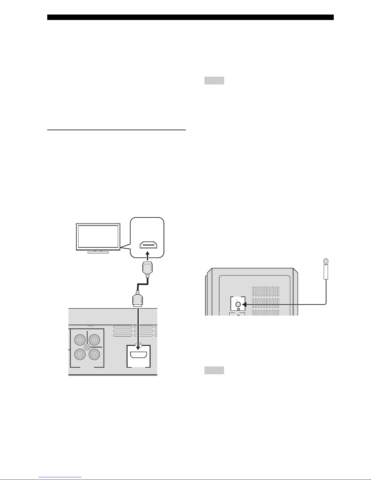
■ Connecting an HDMI component
HDMI (High-Definition Multimedia Interface) is the first
industry-supported, uncompressed, all-digital A/V (audio/
video) interface.
By connecting to an HDMI component (such as a TV),
you can enjoy standard, enhanced or high-definition video
as well as digital audio using a single cable.
When used in combination with HDCP (High-bandwidth
Digital Content Protection), HDMI provides a secure
audio/video interface that meets the security requirements
of content providers and system operators.
For further information on HDMI, visit the HDMI website
at “http://www.hdmi.org/”.
Viewing and Listening to playback
from an HDMI component
To output an HDMI signal, you need to configure the
settings manually. It is necessary to prepare in advance to
output an HDMI signal.
1 Set the system to standby mode.
2 Connect the HDMI terminals on your HDMI
compatible device and the DVD controller using a
commercially available HDMI cable.
3 To output an audio signal from the DVD controller to
the HDMI compatible device, refer to “System menu”
on page 57.
After doing the settings, set the DVD controller to
standby mode, and then turn on the system again.
4 To set the video output according to the HDMI
compatible device, refer to “Video Output” on
page 38 to access the DVD setup menu, and then set
the two items under Video output in the system menu.
– HDMI Resolution
– HDMI Color
Notes
– This unit is designed to connect to HDMI
compatible devices. If you connect to the DVI
component, the system may not operate correctly.
– The DVD controller is not compatible with HDCP-
incompatible HDMI or DVI components.
– You need a commercially available HDMI/DVI
conversion cable when you connect the DVD
controller to other DVI components.
– If you connect the system to the DVI component
with a HDMI/DVI conversion cable, the HDMI
terminal of the DVD controller does not output any
audio signals.
– Do not disconnect or connect the HDMI cable from
the DVD controller or turn off the power of the
HDMI/DVI component connected to the HDMI
OUTPUT terminal of the DVD controller while
data is being transferred. Doing so may disrupt
playback or cause noise.
– PCM signal downmixed to two channels can be
output from the HDMI output terminal.
■ Connecting the FM antenna
Connect an indoor FM antenna to the ANTENNA
terminal. Extend the FM antenna and fix its ends to the
wall.
For better FM stereo reception, connect an external FM
antenna.
Notes
– Adjust the position of the antenna for optimal
reception.
– Position the antenna as far as possible from your
TV, VCR or other sources of radiation to prevent
unwanted interference.
VIDEO
COMPONENT
P
R
VIDEO
OUTPUT
Y
P
B
HDMI
OUTPUT
HDMI
IN
TV
DVD controller
FM
75
UNBAL
.
ANTENNA
INPUT
Subwoofer/system control

OTHER CONNECTIONS
19 En
English
CONNECTIONS
2
■ Connecting external AV
components
If you connect external AV equipment, such as a VCR or
cassette deck, to the audio input terminal on the
subwoofer/system control, you can listen to those audio
sources on the system.
This section provides some examples of VCR and digital
AV equipment connections.
Connecting analog AV components
Connect the DVD controller and external AV equipment
as shown in the illustration.
Connecting digital AV components
Connect the subwoofer/system control and external AV
equipment as shown in the illustration.
When connecting to optical type digital AV
components
When connecting to coaxial type digital
AV components
INPUT
DOCK
OPTICAL
OPTICAL
COAXIAL
ANALOG
TV
VCR (for example)
Subwoofer/system control
INPUT
DOCK
OPTICAL
OPTICAL
COAXIAL
ANALOG
OPTICAL
DIGITAL OUTPUT
OPTICAL
DIGITAL OUTPUT
Digital audio
component
Subwoofer/system control
Game
console
INPUT
DOCK
OPTICAL
OPTICAL
COAXIAL
ANALOG
COAXIAL
DIGITAL OUTPUT
Digital audio
component
OTHER CONNECTIONS
20 En
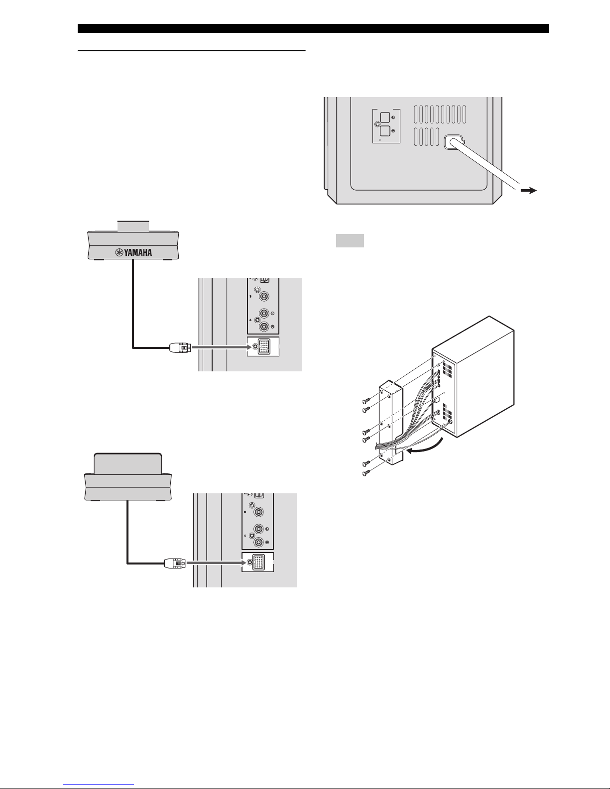
Connecting optional equipment
The system is equipped with the DOCK terminal, which
allows you to connect the Yamaha iPod universal dock
(such as YDS-10 or YDS-11, sold separately) or Yamaha
Bluetooth wireless audio receiver (such as YBA-10, sold
separately). Connect the optional equipment to the DOCK
terminal of the subwoofer/system control using its
dedicated cable.
When connecting the Yamaha iPod
universal dock
When connecting the Yamaha Bluetooth
wireless audio receiver
■ Connecting the power cable
After you have made all connections, connect the power
cable of the subwoofer/system control.
Hint
You can attach or detach the cover according to your
preference after you have made all connections.
Attach the cover to the rear panel of subwoofer/system
control using the 6 supplied screws as shown.
DOCK
OPTICAL
COAXIAL
ANALOG
Yamaha iPod universal dock
(such as YDS-10 or YDS-11, sold separately)
DOCK
OPTICAL
COAXIAL
ANALOG
Y
amaha Bluetooth wireless audio receiver
(such as YBA-10, sold separately)
SPEAKERS
MAINS
SPEAKER
IMPEDANCE
:
6 MIN.
To AC
outlet
21 En
English
PREPARATION
3
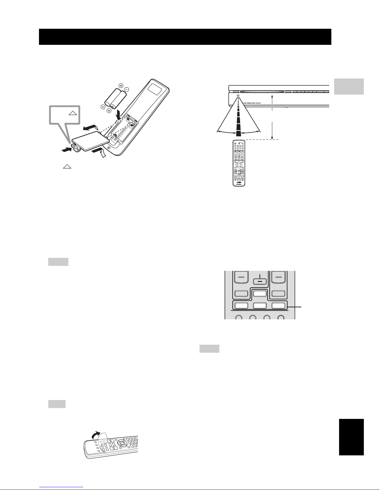
PREPARATION
■ Inserting batteries into the remote
control
1 Press on the battery cover and open the cover.
2 Insert the two supplied batteries (AA, R6, UM-3) into
the battery compartment.
Insert the batteries according to the polarity markings
(+ and –).
3 Close the battery cover.
Replacing the batteries
If the batteries run low, the effective operation distance of the
remote control decreases considerably. If this happens,
replace the batteries with two new ones as soon as possible.
Notes
– Do not use an old battery together with new one.
– Do not use different types of batteries (for
example, alkaline and manganese) together. Each
type of battery has its own characteristics even if
they are similar in shape.
– If the batteries run out, immediately remove them
from the remote control to prevent an explosion or
acid leak.
– Dispose of the batteries according to the regional
regulations.
– If a battery starts leaking, dispose of it
immediately.
Be careful not to let leaking battery acid come into
contact with your skin or clothing. Before inserting
new batteries, wipe the compartment clean.
– Replace the batteries within two minutes to
preserve the preset code in the remote control.
Hint
Remove the transparent sheet before using the remote
control.
■ Using the remote control
Use the remote control within 6 m of the DVD controller
and point it toward the remote control sensor.
Basic operation of the remote control
1 Use the Input selection buttons on the remote control
to select the input source you wish to control (for
example DVD/USB).
→ The selected source appears in the front panel
display.
When the button contains several input sources such
as DVD/USB and INPUT 1-4 buttons, the input
source switches each time you press the button.
2 Operate the desired function (for example, h or b
/ a).
Notes
– Be careful not to spill liquid on the remote control.
– Be careful not to drop the remote control.
– Do not leave the remote control in the following
places:
– hot or humid places, such as near a heater or in a
bathroom
– extremely cold places
– dusty places
– To operate your TV with the remote control, you
need to set the preset code.
Refer to “Setting the preset code” on page 58 for
how to change the preset code.
GETTING STARTED
1
3
2
Press
STANDBY / ON
EJECT
30˚ 30˚
ENTER
TV
/
STB
CH
Within 6 m
TV VOL
VOLUME
TUNER MUTE
TV INPUT
DVD
/
USB INPUT 1-4
POSITION
AREA SOUND TEST
DOCK
CH
Input
selection
buttons
GETTING STARTED
22 En
■ Turn on the system
Press STANDBY/ON on the DVD controller or the
remote control.
The LED indicators beside the disc loading slot light up
when the system is turned on.
SLEEP
NIGHT
ENHANCER
STEREO
GAMESPORTS
MUSIC
FUNC.
WP87020DVX-700
TV STB
POWER
STANDBY
/
ON
10KEY
MOVIE
STANDBY/ON
STANDBY / ON
EJECT
Light up
GETTING STARTED
23 En
PREPARATION
3
English
■ Setting the video input/output
Notes
– Make sure that you have completed all the
necessary connections (Refer to “Connecting a
TV” on page 17).
– If the settings you have selected are not
appropriate, you can reset DVD settings to the
initial factory settings (Refer to “System menu” on
page 57).
1 Press DVD/USB repeatedly until “DVD” appears in
the front panel display.
2 Turn on the TV and set to the correct video-in
channel.
→ You should see the background screen on the TV.
– Usually this channel is between the lowest and
highest channels and may be called FRONT, A/V
IN or VIDEO. See your TV manual for more
details.
– Or, you may go to channel 1 on your TV, then
press the Channel down button repeatedly until you
see the Video In channel.
– Or, the TV remote control may have a button or
switch that chooses different video modes.
Setting the TV display
Set the aspect ratio of the DVD controller according to the
TV you have connected. The format you select must be
available on the disc. If it is not, the TV display setting
will not affect the picture during playback.
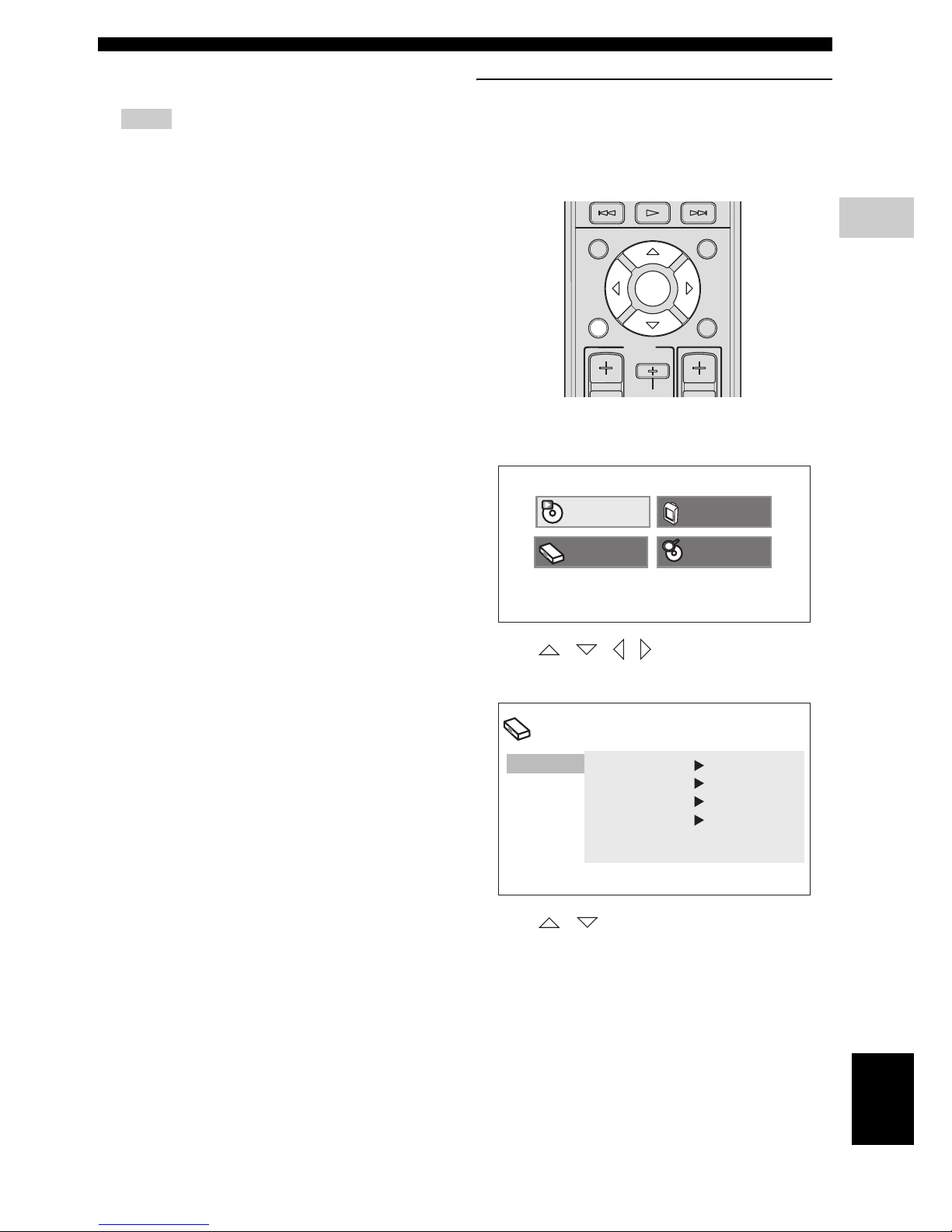
1 Press SETUP on the remote control.
DVD setup menu is displayed on the screen.
2 Press / / / on the remote control to
highlight [Initial Settings], and then press ENTER.
3 Press / on the remote control to highlight
[Video Output], and then press ENTER.
INFO.
A-E A-E
MENU
TOP MENU
SETUP RETURN
CODE SET
PRESET
ENTER
TV
/
STB
CH
Play Mode
Initial Setting
Disc Navigator
Video Adjust
Initial Setting
Video Output
Language
Display
Options
TV Screen 4:3 (Letter Box)
Component Out
Interlace
HDMI Resolution
720x480p
HDMI Color Component
GETTING STARTED
24 En
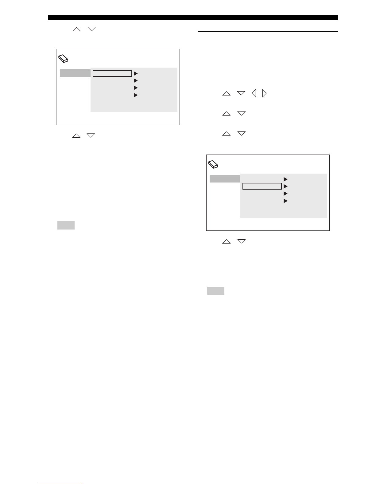
4 Press / on the remote control to highlight
[TV Screen], and then press ENTER.
5 Press / on the remote control to highlight one
of the options below, and then press ENTER.
4:3 (Letter Box)
Select this if you have a conventional TV. In this case, a
wide picture with black bar on the upper and lower
portions of the TV screen will be displayed.
4:3 (Pan&Scan)
Select this if you have a conventional TV and want both
sides of the picture to be trimmed or formatted to fit your
TV screen.
Note
If the disc does not support an aspect ratio of 4:3
(Pan&Scan), the content is displayed in 4:3 (Letter
Box).
16:9 (Wide)
Select this if you have a wide-screen TV.
16:9 (Compressed)
Select this if a wide-screen TV is connected to the DVD
controller with an HDMI cable, and set HDMI Resolution
to either [1920 x 1080p], [1920 x 1080i], or [1280 x
720p]. When playing back a content whose aspect ratio is
4:3, black bars cover the sides of the screen.
Selecting the output type for
COMPONENT VIDEO OUTPUT jacks
To use progressive display function, connect to a TV,
which has that function, via COMPONENT VIDEO
OUTPUT jacks.
1 Press SETUP on the remote control.
2 Press / / / on the remote control to
highlight [Initial Settings], and then press ENTER.
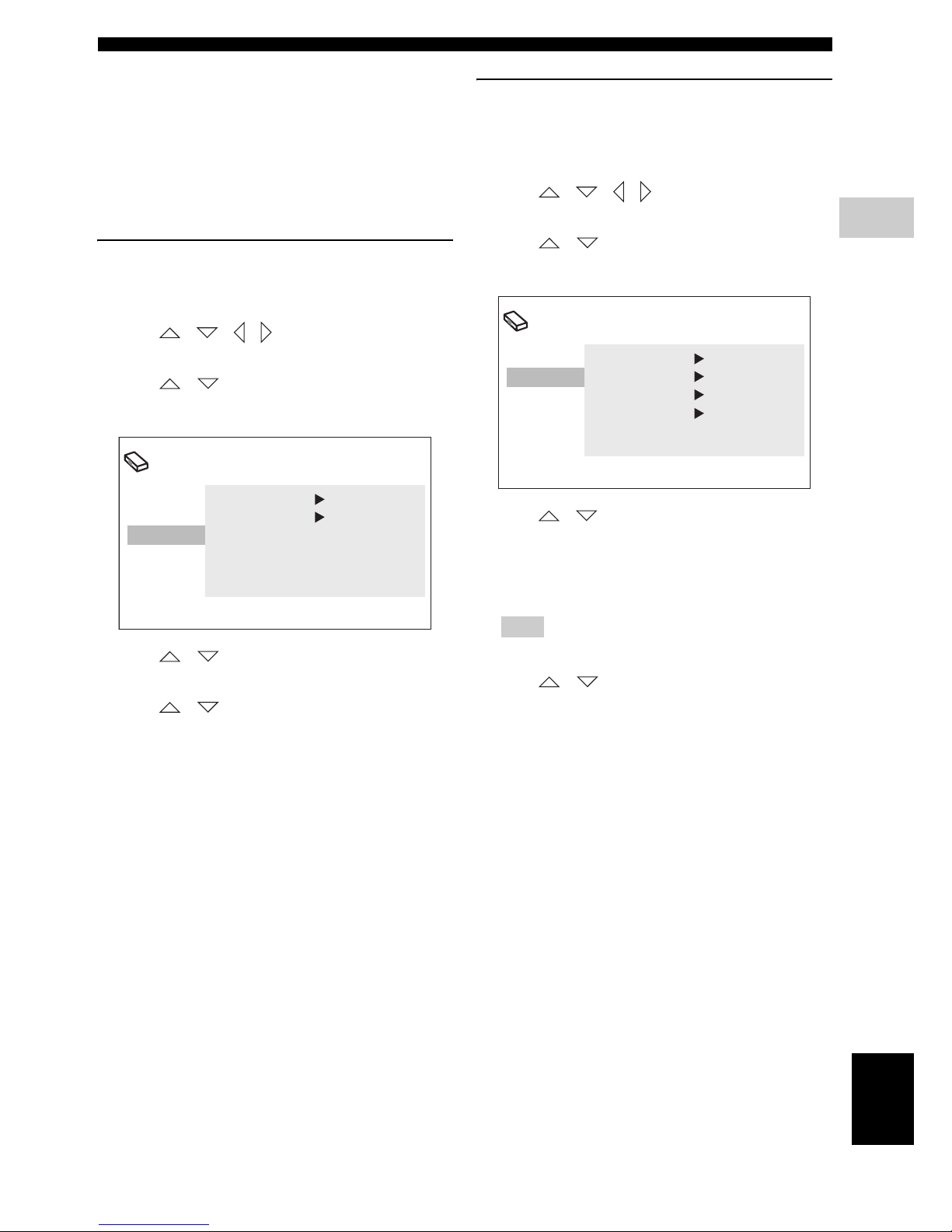
3 Press / on the remote control to highlight
[Video Output], and then press ENTER.
4 Press / on the remote control to highlight
[Component Out], and then press ENTER.
5 Press / on the remote control to highlight
[Progressive] / [Interlace], and then press ENTER.
6 When the confirmation screen appears, press ENTER
again.
To cancel the setting, press RETURN.
Note
Do not select [Progressive] if your TV does not have a
progressive display function.
If your TV is also connected via HDMI OUTPUT
terminal, the system may ignore this setting and
output the progressive signal from COMPONENT
VIDEO OUTPUT jacks.
Initial Setting
Video Output
Language
Display
Options
TV Screen 4:3 (Letter Box)
Component Out
Interlace
HDMI Resolution
720x480p
HDMI Color Component
Initial Setting
Video Output
Language
Display
Options
TV Screen 4:3 (Letter Box)
Component Out Interlace
HDMI Resolution
720x480p
HDMI Color Component
GETTING STARTED
25 En
PREPARATION
3
English
■ Setting language preferences
You can select your preferred language settings so that
this controller will automatically switch to your preferred
language whenever you load a disc. If the language
selected is not available on the disc, the disc’s default
setting language will be used instead. The OSD (on-screen
display) language for the DVD setup menu will remain as
you set it, regardless of various disc languages.
On-screen display (OSD) language
1 Press SETUP on the remote control.
DVD setup menu appears on the screen.
2 Press / / / on the remote control to
highlight [Initial Settings], and then press ENTER.
3 Press / on the remote control to highlight
[Display], and then press ENTER.
4 Press / on the remote control to highlight
[OSD Language], and then press ENTER.
5 Press / on the remote control to select a
language, and then press ENTER.
Audio, Subtitle and Disc menu
languages
1 Press SETUP on the remote control.
DVD setup menu appears on the screen.
2 Press / / / on the remote control to
highlight [Initial Settings], and then press ENTER.
3 Press / on the remote control to highlight
[Language], and then press ENTER.
4 Press / on the remote control to highlight the
item below, and then press ENTER.
– Audio Language
– Subtitle Language
– DVD Menu Language
Hint
Refer to page 40 for the other items.
5 Press / on the remote control to select a
language, and then press ENTER.
Initial Setting
Video Output
Language
Display
Options
OSD Language English
Angle Indicator
On
Initial Setting
Video Output
Language
Display
Options
Audio Language English
Subtitle Language English
DVD Menu Lang. English
Subtitle Display On
26 En
BASIC OPERATIONS
This unit is designed for use with DVD, CD, Video CD,
and Super Video CD, as well as DivX® files and WMV
files recorded on CD-R or DVD-R/DVD+R.
IMPORTANT!
– DVD discs and players are designed with regional
restrictions. Before playing a disc, make sure that
the disc is for the same zone as your DVD
controller.
– Do not insert any objects other than discs into the
disc loading slot. Doing so may cause the DVD
controller to malfunction.
– Depending on the disc, some functions may be
prohibited.
– This unit is not compatible with 8-cm discs.
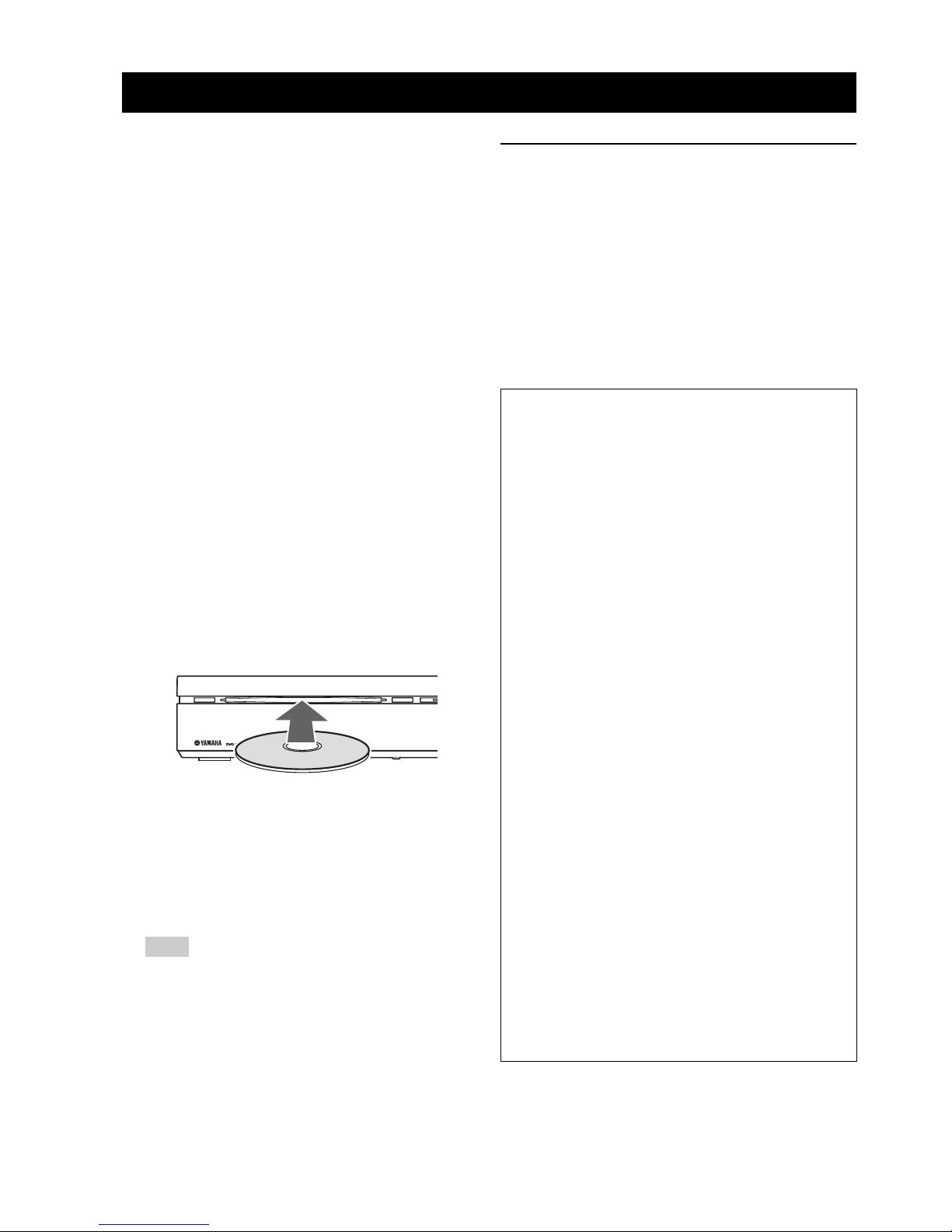
■ Playing discs
1 Turn on the system.
2 Press DVD/USB repeatedly until “DVD” appears in
the front panel display.
3 Turn on the TV power and set to the correct Video-in
channel (Refer to “Setting the video input/output” on
page 23).
→ You should see the background screen on the TV.
4 Insert the disc into the disc loading slot.
5 Press h to start playback.
→ If a disc menu appears on the TV, refer to “Using
the disc menu (DVD only)” on page 28.
→ If the disc is locked by parental lock function, you
must enter your 4-digit password (Refer to “Parental
Lock” on page 41).
Note
If you do the operation that is not available during
playback, a message “This operation can’t be
performed.” or “Depending on the disc, this operation
may be prohibited.” appears.
Playing DivX® video/WMV files
DivX® video file
This unit can play DivX
®
videos recorded on CD-R/RW,
DVD-R/-RW, DVD+R/+RW discs. By default they will
be played in alphabetical order. The supported files are
shown below.
– Plays all versions of DivX
®
video (including
DivX
®
6) with enhanced playback of DivX®
media files and the DivX
®
media format.
– The following filename extensions are supported
“.avi” and “.divx”.
DISC OPERATION
STANDBY / ON
EJECT
Displaying external subtitle files
The font sets listed below are available for external
subtitle files. You can see the proper font set on-screen
by setting [Subtitle Language] to match the subtitle
file.
– Some external subtitle files may be displayed
incorrectly or not at all.
– For external subtitle files, the following subtitle
format filename extensions are supported:
“.srt”, “.sub”, “.ssa”, “.smi”
– The filename of the movie file has to be
repeated at the beginning of the filename for the
external subtitle file.
– The number of external subtitle files which can
be switched for the same movie file is limited to
a maximum of 10.
Group 1
Albanian (sq), Basque (eu), Catalan (ca),
Danish (da), Dutch (nl), English (en),
Faroese (fo), Finnish (fi), French (fr),
German (de), Icelandic (is), Irish (ga),
Italian (it), Norweigian (no),
Portuguese (pt), Rhaeto-Romanic (rm),
Scottish (gd), Spanish (es), Swedish (sv)
Group 2
Albanian (sq), Croatian (hr), Czech (cs),
Hungarian (hu), Polish (pl),
Romanian (ro), Slovak (sk),
Slovenian (sl)
Group 3
Bulgarian (bg), Byelorussian (be),
Macedonian (mk), Russian (ru),
Serbian (sr), Ukrainian (uk)
Group 4
Hebrew (iw), Yiddish (ji)
Group 5
Turkish (tr)
 Loading...