

Page 1
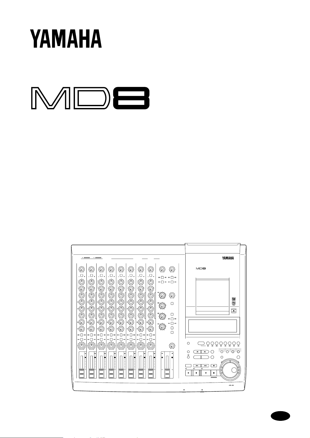
MULTITRACK MD RECORDER
Owner’s Manual
1 2 345678 9101112 1 2INSERT I/O INSERT I/O
1
GAIN
GAIN
LINE
LINE
MIC
PB MIC/
PB MIC/
LINE
FLIP
CUE
CUE
P
A
N
LR
LR
L
E
V
E
L
010
010
HIGH
HIGH
–15 +15
–15 +15
MID
MID
F
F
250 5k
250 5k
G
G
–15 +15
–15 +15
LOW
LOW
–15 +15
–15 +15
AUX
AUX
1
1
010
010
2
2
010
010
1 2
1 2
GROUP ASSIGN
GROUP ASSIGN
3 4
3 4
PAN
PAN
L
L
ODDREVEN
ODDREVEN
10
10
9
9
8
8
7
7
6
6
5
5
4
4
3
3
2
2
1
1
0
0
1
MIC/LINE INPUT LINE INPUT AUX SEND
7
6
5
4
3
2
GAIN
LINE
MIC
PB MIC/
LINE
FLIP
FLIP
CUE
P
A
N
LR
L
E
V
E
L
010
HIGH
–15 +15
MID
F
250 5k
G
–15 +15
LOW
–15 +15
AUX
1
010
2
010
1 2
GROUP ASSIGN
3 4
PAN
L
ODDREVEN
10
9
8
7
6
5
4
3
2
1
0
2
GAIN
GAIN
LINE
LINE
MIC
MIC
PB MIC/
PB MIC/
LINE
LINE
3
CUE
P
A
N
L
E
V
E
L
HIGH
MID
F
G
LOW
AUX
1
2
GROUP ASSIGN
PAN
ODDREVEN
10
9
8
7
6
5
4
3
2
1
0
FLIP
LR
010
–15 +15
250 5k
–15 +15
–15 +15
010
010
1 2
3 4
L
4
CUE
P
A
N
L
E
V
E
L
HIGH
MID
F
G
LOW
AUX
1
2
GROUP ASSIGN
PAN
ODDREVEN
10
9
8
7
6
5
4
3
2
1
0
FLIP
LR
010
–15 +15
250 5k
–15 +15
–15 +15
010
010
1 2
3 4
L
GAIN
GAIN
LINE
PB MIC/
FLIP
LR
010
–15 +15
250 5k
–15 +15
–15 +15
010
010
1 2
3 4
L
6
LINE
MIC
CUE
P
A
N
L
E
V
E
L
HIGH
MID
F
G
LOW
AUX
1
2
GROUP ASSIGN
PAN
ODDREVEN
10
9
8
7
6
5
4
3
2
1
0
PB MIC/
FLIP
LR
010
–15 +15
250 5k
–15 +15
–15 +15
010
010
1 2
3 4
L
7
MIC
LINE
P
A
N
L
E
V
E
L
LINE
MIC
LINE
CUE
P
A
N
L
E
V
E
L
HIGH
MID
F
G
LOW
AUX
1
2
GROUP ASSIGN
PAN
ODDREVEN
10
9
8
7
6
5
4
3
2
1
0
5
8
GAIN
LINE
MIC
PB MIC/
LINE
FLIP
CUE
P
A
N
LR
L
E
V
E
L
010
HIGH
–15 +15
MID
F
250 5k
G
–15 +15
LOW
–15 +15
AUX
1
010
2
010
1 2
GROUP ASSIGN
3 4
PAN
L
ODDREVEN
10
9
8
7
6
5
4
3
2
1
0
8 STEREO
9-10
11-12
010010
1
2 1 2
GROUP ASSIGN GROUP ASSIGN
3 4 3 4
CUE
GROUP
MASTER
MASTER
1
010
010
CUE MIX
TO STEREO
2
010
MONITOR
SELECT
2TR IN
3
1 3
010
GROUP
2 4
4
STEREO
010
CUE
MONITOR
LEVEL
MIN MAX
10
10
9
9
8
8
7
7
6
6
5
5
4
4
3
3
2
2
1
1
0
0
MULTITRACK MD RECORDER
DISPLAY
REPEAT MARK SEARCH MARK
A B LAST REC SEARCH SET EXIT
AUTO
PUNCH I/O SONG SEARCH PAUSE
CH 1 CH 2 CH 3 CH 4 CH 5 CH 6 CH 7 CH 8
GROUP 1
12341234
IN OUT
REHE REC PLAY STOP
PHONES PUNCH I/O
REC SELECT
2345678
ADJUSTPITCH EDIT UTILITY
ENTER
TOC WRITE
DATA
CURSOR
+ –
E
Page 2
ADVARSEL
Usynlig laserstråling ved åbning. Undgå udsaettelse
for stråling.
VAROITUS
Laitteen käyttäminen muulla kuin tässä käyttöohjeesa
mainitulla tavalla saattaa altistaa käyttäjän
turvallisuusluokan 1 ylittävälle näkymättömälle
lasersäteilylle.
VARNING
Om apparaten används på annat sätt än i denna
bruksanvisning specificerats, kan användaren utsättas
för osynlig laserstrålning, som överskrider gränsen för
laserklass 1.
FCC INFORMATION (U.S.A.)
1. IMPORTANT NOTICE: DO NOT MODIFY THIS UNIT!
This product, when installed as indicated in the instructions contained in this
manual, meets FCC requirements. Modifications not expressly approved by
Yamaha may void your authority, granted by the FCC, to use the product.
2. IMPORTANT: When connecting this product to accessories and/or another
product use only high quality shielded cables. Cable/s supplied with this product
MUST be used. Follow all installation instructions. Failure to follow instructions
could void your FCC authorization to use this product in the USA.
3. NOTE: This product has been tested and found to comply with the requirements
listed in FCC Regulations, Part 15 for Class “B” digital devices. Compliance
with these requirements provides a reasonable level of assurance that your use of
this product in a residential environment will not result in harmful interference
with other electronic devices. This equipment generates/uses radio frequencies
and, if not installed and used according to the instructions found in the users
manual, may cause interference harmful to the operation of other electronic
devices. Compliance with FCC regulations does not guarantee that interference
will not occur in all installations. If this product is found to be the source of
interference, which can be determined by turning the unit “OFF” and “ON”,
please try to eliminate the problem by using one of the following measures:
Relocate either this product or the device that is being affected by the
interference.
Utilize power outlets that are on different branch (circuit breaker or fuse)
circuits or install AC line filter/s.
In the case of radio or TV interference, relocate/reorient the antenna. If the
antenna lead-in is 300 ohm ribbon lead, change the lead-in to coaxial type cable.
If these corrective measures do not produce satisfactory results, please contact
the local retailer authorized to distribute this type of product. If you can not
locate the appropriate retailer, please contact Yamaha Corporation of America,
Electronic Service Division, 6600 Orangethorpe Ave, Buena Park, CA 90620
IMPORTANT
Please record the serial number of this unit in the space below.
Laser Diode Properties
* Material : GaAlAs
* Wavelength : 780–790 nm
* Emission Duration : Continuous
* Laser Output Power : Less than 44.6 µW
(Note)
Laser output is measured at a
distance of 20cm from the object
lens on the optical pick-up head.
This unit is classified as a
Class 1 laser product.
CLASS 1 LASER PRODUCT
CLASS 1 LASER PRODUCT
LUOKAN 1 LASERLAITE
KLASS 1 LASERAPPARAT
CAUTION : INVISIBLE LASER RADIATION WHEN OPEN AND INTRLOCKS DEFEATED.
DO NOT STARE INTO BEAM OR VIEW DIRECTLY WITH OPTICAL INSTRUMENTS.
VARNING : OSYNLIG LASERSTRÅLNING NÄR DENNA DEL ÄR ÖPPNAD OCH SPÄRRAR
ÄR URKOPPLADE. STIRRA EJ IN I STRÅLEN OCH BETRAKTA EJ STRÅLEN MED
OPISKA INSTRUMENT.
VARO! : NÄKYMÄTÖNTÄ AVATTAESSA JA SUOJALUKITUS OHITETTAESSA OLET
ALTTIINA LASERSÄTEILYLLE. ÄLÄ TUIJOTA SÄTEESEEN ÄLÄKÄ KATSO SITÄ
OPTISEN LAITTEEN LÄPI.
The CLASS 1 LASER
PRODUCT label is located on
the exterior.
Klassmärkning för Finland.
•This label is not placed on USA
model and Canadian model.
•This label is placed on the lid.
•Varningsanvisning för
laserstrålning. Placerad i
apparaten.
Serial No.:
The serial number is located on the bottom of the unit.
Retain this Owner's Manual in a safe place for future reference.
IMPORTANT NOTICE FOR
THE UNITED KINGDOM
Connecting the Plug and Cord
IMPORTANT: The wires in this mains lead are coloured in accordance
with the following code:
BLUE : NEUTRAL
BROWN : LIVE
As the colours of the wires in the mains lead of this apparatus may not
correspond with the coloured markings identifying the terminals in your
plug proceed as follows:
The wire which is coloured BLUE must be connected to the terminal
which is marked with the letter N or coloured BLACK.
The wire which is coloured BROWN must be connected to the terminal
which is marked with the letter L or coloured RED.
Making sure that neither core is connected to the earth terminal of the
three pin plug.
CAUTION
USE OF CONTROLS OR ADJUSTMENTS OR
PERFORMANCE OF PROCEDURES OTHER
THAN THOSE SPECIFIED HEREIN MAY RESULT
IN HAZARDOUS RADIATION EXPOSURE.
Page 3
• Explanation of Graphical Symbols
CAUTION
RISK OF ELECTRIC SHOCK
DO NOT OPEN
CAUTION: TO REDUCE THE RISK OF
ELECTRIC SHOCK, DO NOT REMOVE
COVER (OR BACK). NO USER-SERVICEABLE
PARTS INSIDE. REFER SERVICING TO
QUALIFIED SERVICE PERSONNEL.
SEE BOTTOM OF ENCLOSURE FOR GRAPHIC
SYMBOLS MARKING.
SAFETY INSTRUCTIONS
1. Read Instructions — All the safety and operating instructions
should be read before the appliance is operated.
2. Retain Instructions — The safety and operating instructions
should be retained for future reference.
3. Heed Warnings — All warnings on the appliance and in the
operating instructions should be adhered to.
4. Follow Instructions — All operating and use instructions
should be followed.
5. Water and Moisture — The appliance should not be used near
water – for example, near a bathtub, washbowl, kitchen sink,
laundry tub, in a wet basement, or near a swimming pool, and
the like.
6. Carts and Stands — The appliance
should be used only with a cart or stand
that is recommended by the manufacturer.
6A An appliance and cart combination
should be moved with care. Quick
stops, excessive force, and uneven
surfaces may cause the appliance and cart combination to
overturn.
7. Wall or Ceiling Mounting — The appliance should be mounted
to a wall or ceiling only as recommended by the manufacturer.
8. Ventilation — The appliance should be situated so that its
location or position does not interfere with its proper ventilation. For example, the appliance should not be situated on a
bed, sofa, rug, or similar surface that may block the ventilation
openings; or, placed in a built-in installation, such as a
bookcase or cabinet that may impede the flow of air through
the ventilation openings.
9. Heat — The appliance should be situated away from heat
sources such as radiators, heat registers, stoves, or other
appliances (including amplifiers) that produce heat.
The exclamation point within an equilateral triangle is intended to alert the user to
the presence of important operating and
maintenance (servicing) instructions in the
literature accompanying the product.
The lightning flash with arrowhead symbol
within an equilateral triangle is intended to
alert the user to the presence of uninsulated
“dangerous voltage” within the product’s
enclosure that may be of sufficient magnitude to constitute a risk of electric shock to
persons.
10. Power Sources — The appliance should be connected to a
power supply only of the type described in the operating
instructions or as marked on the appliance.
11. Grounding or Polarization — The precautions that should be
taken so that the grounding or polarization means of an
appliance is not defeated.
12. Power-Cord Protection — Power-supply cords should be
routed so that they are not likely to be walked on or pinched by
items placed upon or against them, paying particular attention
to cords at plugs, convenience receptacles, and the point where
they exit from the appliance.
13. Cleaning — The appliance should be cleaned only as recommended by the manufacturer.
14. Nonuse Periods — The power cord of the appliance should be
unplugged from the outlet when left unused for a long period
of time.
15. Object and Liquid Entry — Care should be taken so that
objects do not fall and liquids are not spilled into the enclosure
through openings.
16. Damage Requiring Service — The appliance should be serviced by qualified service personnel when:
A. The power-supply cord or the plug has been damaged; or
B. Objects have fallen, or liquid has been spilled into the
appliance; or
C. The appliance has been exposed to rain; or
D. The appliance does not appear to operate normally or
exhibits a marked change in performance; or
E. The appliance has been dropped, or the enclosure dam-
aged.
17. Servicing — The user should not attempt service the appliance
beyond that described in the operating instructions.
Page 4

ii
Important
Read the Following Before Operating the MD8
Warnings
• Do not locate the MD8 in a place subject to excessive heat or direct sunlight. This could
be a fire hazard.
• Do not place MD8 in a place subject to excessive humidity or dust. This could be a fire
or electrical shock hazard.
• Connect the supplied AC power cord only to an AC outlet of the type stated in this
Owner’s Manual or as marked on the MD8. Failure to do so is a fire and electrical shock
hazard.
• Do not plug several devices into the same AC outlet. This may overload the AC outlet,
and can be a fire and electrical shock hazard. It ma y also affect the performance of some
devices.
• Do not place heavy objects on the power cord. A damaged power cord is a potential fire
and electrical shock hazard.
• If the power cord is damaged (i.e., cut or a bare wire is exposed), ask your dealer for a
replacement. Using the MD8 in this condition is a fire and shock hazard.
• Hold the AC power cord plug when disconnecting from an AC outlet. Never pull the
cord. Damaging the po wer co rd in this wa y is a potential fir e and electrical shock hazard.
• Do not place small metal objects on top of the MD8. Metal objects inside the MD8 are a
fire and electrical shock hazard.
• Do not block the MD8 ventilation holes above and behind the disc compartment. These
vents are to prevent the int ernal temperature from rising. Block ed vents ar e a fire hazar d.
• Do not try to modify the MD8. This could be a fire and electrical shock hazard.
• The MD8 operating temperature is between 5˚C and 35˚C (41˚F and 95˚F).
Cautions
• Turn off all audio devices and speakers when connecting to the MD8. Refer to the
owner’s manual for each device. Use the correct cables and connect as specified.
• The MD8 is a precision device. Handle it with care.
• Handle MD DATA discs with care.
• If you notice any abnormality—such as smoke, odor, or noise—turn off the MD8
immediately , remove the AC power cord fr om the AC outlet, confirm that the abnormality is no longer present, and then consult your dealer for repair. Using the MD8 in this
condition is a fire and shock hazard.
• If a foreign object or water gets inside the MD8, turn it off immediately, remove the AC
power cord from the AC outlet, and then consult your dealer for repair. Using the MD8
in this condition is a fire and electrical shock hazard.
• If you plan not to use the MD8 for a long period of time (such as when you are on vacation), remove the AC power cord from the AC outlet. Leaving the MD8 connected is a
fire hazard.
• Do not use benzene, thinner, cleaning detergent, or a chemical cloth to clean the MD8.
Use a soft, dry cloth.
MD8—Owner’s Manual
Page 5

iii
Ventilation
Allow a distance of 10 cm between the unit and the wall so that heat generated from the unit
will be released effectively. Also , allow enough space between the unit and other devices. If
you mount the unit in an audio rack, keep a space of 10 cm to the side panel. Remove the
rear panel of the rack or open a vent hole. If heat release is inadequate, the unit will retain
heat inside the unit, which may cause a fire.
Interference
The MD8 uses high-frequency digital circuits that may cause interference on radios and televisions placed close to it. If interference does occur, relocat e the affect ed equipment.
Copyright
© 1997 Yamaha C orporation. All rights reserved.
No part of the MD8 software or this
any form or by any means without the prior written authorization of Yamaha Corporation.
Owner’s Manual may be reproduced or distributed in
Trademarks
MD DATA and MiniDisc are trademarks of Sony Corporation.
US and foreign patents licensed from Dolby Laboratories Licensing Corporation.
All other trademarks are the property of their respective holders.
Package Contents
The MD8 package should contain the following items. M ake sure that you have them all.
• MD8 Multitrack MD Recorder
• AC power cord
• This Owner’s Manual
Contact your Yamaha dealer if something is missing.
Keep This Manual For Future Reference
MD8—Owner’s Manual
Page 6

iv
Contents
1. Welcome to the MD8 . . . . . . . . . . . . . . . . 1
MD8 Features . . . . . . . . . . . . . . . . . . . . . . . . . . . . . . . . . . . . . . . . . . . . . . . . . . 1
Buying Discs for the MD8 . . . . . . . . . . . . . . . . . . . . . . . . . . . . . . . . . . . . . . . . 3
MD8 TOC . . . . . . . . . . . . . . . . . . . . . . . . . . . . . . . . . . . . . . . . . . . . . . . . . . . . . 3
2. Touring the MD8 . . . . . . . . . . . . . . . . . . . . 4
Topside View . . . . . . . . . . . . . . . . . . . . . . . . . . . . . . . . . . . . . . . . . . . . . . . . . . . 4
Input Channels . . . . . . . . . . . . . . . . . . . . . . . . . . . . . . . . . . . . . . . . . . . . . . . . . 5
Master Section . . . . . . . . . . . . . . . . . . . . . . . . . . . . . . . . . . . . . . . . . . . . . . . . . . 7
Display . . . . . . . . . . . . . . . . . . . . . . . . . . . . . . . . . . . . . . . . . . . . . . . . . . . . . . . . 8
Disc Transport Section . . . . . . . . . . . . . . . . . . . . . . . . . . . . . . . . . . . . . . . . . . . 10
Rear Panel . . . . . . . . . . . . . . . . . . . . . . . . . . . . . . . . . . . . . . . . . . . . . . . . . . . . . 12
Front Connectors . . . . . . . . . . . . . . . . . . . . . . . . . . . . . . . . . . . . . . . . . . . . . . . 15
Mixer . . . . . . . . . . . . . . . . . . . . . . . . . . . . . . . . . . . . . . . . . . . . . . . . . . . . 1
Recorder . . . . . . . . . . . . . . . . . . . . . . . . . . . . . . . . . . . . . . . . . . . . . . . . . 1
3. The First Session . . . . . . . . . . . . . . . . . . . 16
Quick-Start System . . . . . . . . . . . . . . . . . . . . . . . . . . . . . . . . . . . . . . . . . . . . . . 16
Connecting the Power Cord . . . . . . . . . . . . . . . . . . . . . . . . . . . . . . . . . . . . . . . 17
Turning on the MD8 . . . . . . . . . . . . . . . . . . . . . . . . . . . . . . . . . . . . . . . . . . . . 17
Loading a Disc . . . . . . . . . . . . . . . . . . . . . . . . . . . . . . . . . . . . . . . . . . . . . . . . . . 17
Recording the First Track . . . . . . . . . . . . . . . . . . . . . . . . . . . . . . . . . . . . . . . . . 17
Making the Connections (GRP & DIR) . . . . . . . . . . . . . . . . . . . . . . . . 18
GRP Method . . . . . . . . . . . . . . . . . . . . . . . . . . . . . . . . . . . . . . . . . . . . . 18
DIR Method . . . . . . . . . . . . . . . . . . . . . . . . . . . . . . . . . . . . . . . . . . . . . . 19
Monitoring & Recording (GRP & DIR) . . . . . . . . . . . . . . . . . . . . . . . 19
Listening to the First Track . . . . . . . . . . . . . . . . . . . . . . . . . . . . . . . . . . 19
Overdubbing . . . . . . . . . . . . . . . . . . . . . . . . . . . . . . . . . . . . . . . . . . . . . . . . . . . 20
Mixdown . . . . . . . . . . . . . . . . . . . . . . . . . . . . . . . . . . . . . . . . . . . . . . . . . . . . . . 21
An Overview of Multitrack Recording . . . . . . . . . . . . . . . . . . . . . . . . . . . . . . 22
Basic Multitracking . . . . . . . . . . . . . . . . . . . . . . . . . . . . . . . . . . . . . . . . 22
Advanced Multitracking . . . . . . . . . . . . . . . . . . . . . . . . . . . . . . . . . . . . 22
About Monitoring . . . . . . . . . . . . . . . . . . . . . . . . . . . . . . . . . . . . . . . . . . . . . . . 23
Multi-Source Mixing . . . . . . . . . . . . . . . . . . . . . . . . . . . . . . . . . . . . . . . . . . . . 24
4. Recording & Mixing Techniques . . . . . . . 26
Recording a New Song . . . . . . . . . . . . . . . . . . . . . . . . . . . . . . . . . . . . . . . . . . . 26
Searching for Blanks . . . . . . . . . . . . . . . . . . . . . . . . . . . . . . . . . . . . . . . 26
Setting the Recording Mode . . . . . . . . . . . . . . . . . . . . . . . . . . . . . . . . . 27
Recording . . . . . . . . . . . . . . . . . . . . . . . . . . . . . . . . . . . . . . . . . . . . . . . . 28
Titling Discs & Songs . . . . . . . . . . . . . . . . . . . . . . . . . . . . . . . . . . . . . . . . . . . . 28
Manual Punch In/Out . . . . . . . . . . . . . . . . . . . . . . . . . . . . . . . . . . . . . . . . . . . 29
Using the REC Button . . . . . . . . . . . . . . . . . . . . . . . . . . . . . . . . . . . . . . 29
Using the REC SELECT buttons . . . . . . . . . . . . . . . . . . . . . . . . . . . . . 30
Using a Footswitch . . . . . . . . . . . . . . . . . . . . . . . . . . . . . . . . . . . . . . . . 31
Auto Punch In/Out . . . . . . . . . . . . . . . . . . . . . . . . . . . . . . . . . . . . . . . . . . . . . . 32
Setting the In/Out Points “On-the-Fly” . . . . . . . . . . . . . . . . . . . . . . . 32
Single Take Auto Punch In/Out . . . . . . . . . . . . . . . . . . . . . . . . . . . . . . 34
Multi Take Auto Punch In/Out . . . . . . . . . . . . . . . . . . . . . . . . . . . . . . 37
Setting the Pre-Roll & Post-Roll Times . . . . . . . . . . . . . . . . . . . . . . . . 40
MD8—Owner’s Manual
Page 7

Ping-Pong Recording . . . . . . . . . . . . . . . . . . . . . . . . . . . . . . . . . . . . . . . . . . . 41
Preparing for Ping-Pong . . . . . . . . . . . . . . . . . . . . . . . . . . . . . . . . . . . 42
Rehearsing Ping-Pong . . . . . . . . . . . . . . . . . . . . . . . . . . . . . . . . . . . . . 43
Performing Ping-Pong for Real . . . . . . . . . . . . . . . . . . . . . . . . . . . . . 43
Checking the Ping-Pong Operation . . . . . . . . . . . . . . . . . . . . . . . . . . 43
Ping-Pong with Overdub . . . . . . . . . . . . . . . . . . . . . . . . . . . . . . . . . . . . . . . . 44
Pitch . . . . . . . . . . . . . . . . . . . . . . . . . . . . . . . . . . . . . . . . . . . . . . . . . . . . . . . . . 46
Adjusting the Pitch . . . . . . . . . . . . . . . . . . . . . . . . . . . . . . . . . . . . . . . . 46
Toggling Between FIX & VARI Pitch . . . . . . . . . . . . . . . . . . . . . . . . . 46
Using a Footswitch . . . . . . . . . . . . . . . . . . . . . . . . . . . . . . . . . . . . . . . . . . . . . 47
Applying Effects . . . . . . . . . . . . . . . . . . . . . . . . . . . . . . . . . . . . . . . . . . . . . . . . 48
Applying Effects at Mixdown . . . . . . . . . . . . . . . . . . . . . . . . . . . . . . . . . . . . . 48
Applying Effects when Recording . . . . . . . . . . . . . . . . . . . . . . . . . . . . . . . . . 49
Applying Effects with Ping-Pong . . . . . . . . . . . . . . . . . . . . . . . . . . . . . . . . . . 49
Patching in Signal Processors . . . . . . . . . . . . . . . . . . . . . . . . . . . . . . . . . . . . . 50
5. Quick Search Functions . . . . . . . . . . . . . . 51
Searching for Songs . . . . . . . . . . . . . . . . . . . . . . . . . . . . . . . . . . . . . . . . . . . . . 51
Rewind & Fast Forward . . . . . . . . . . . . . . . . . . . . . . . . . . . . . . . . . . . . . . . . . . 51
Shuttle Playback Function (Cue/Review) . . . . . . . . . . . . . . . . . . . . . 51
Locating Specific Points . . . . . . . . . . . . . . . . . . . . . . . . . . . . . . . . . . . . 52
Searching for the Last Rec IN & OUT Points . . . . . . . . . . . . . . . . . . . . . . . . 52
Searching for Markers . . . . . . . . . . . . . . . . . . . . . . . . . . . . . . . . . . . . . . . . . . . 53
Inserting Markers . . . . . . . . . . . . . . . . . . . . . . . . . . . . . . . . . . . . . . . . . . . . . . 53
Marker Indicators . . . . . . . . . . . . . . . . . . . . . . . . . . . . . . . . . . . . . . . . 53
Adjusting Markers . . . . . . . . . . . . . . . . . . . . . . . . . . . . . . . . . . . . . . . . . . . . . . 54
Erasing Markers . . . . . . . . . . . . . . . . . . . . . . . . . . . . . . . . . . . . . . . . . . . . . . . . 56
v
6. Repeat, Cue List & Program Play . . . . . . 57
One Song Repeat . . . . . . . . . . . . . . . . . . . . . . . . . . . . . . . . . . . . . . . . . . . . . . . 57
All Song Repeat . . . . . . . . . . . . . . . . . . . . . . . . . . . . . . . . . . . . . . . . . . . . . . . . 57
A–B Repeat . . . . . . . . . . . . . . . . . . . . . . . . . . . . . . . . . . . . . . . . . . . . . . . . . . . . 58
Cue List Playback & Copy . . . . . . . . . . . . . . . . . . . . . . . . . . . . . . . . . . . . . . . . 59
Program Playback . . . . . . . . . . . . . . . . . . . . . . . . . . . . . . . . . . . . . . . . . . . . . . 60
7. Editing Songs & Tracks . . . . . . . . . . . . . . 61
Viewing Disc Contents . . . . . . . . . . . . . . . . . . . . . . . . . . . . . . . . . . . . . . . . . . 61
Erasing Discs . . . . . . . . . . . . . . . . . . . . . . . . . . . . . . . . . . . . . . . . . . . . . . . . . . 62
Copying & Converting Songs . . . . . . . . . . . . . . . . . . . . . . . . . . . . . . . . . . . . . 62
Renumbering Songs . . . . . . . . . . . . . . . . . . . . . . . . . . . . . . . . . . . . . . . . . . . . 64
Moving Songs . . . . . . . . . . . . . . . . . . . . . . . . . . . . . . . . . . . . . . . . . . . . . . . . . . 65
Dividing Songs . . . . . . . . . . . . . . . . . . . . . . . . . . . . . . . . . . . . . . . . . . . . . . . . . 66
Combining Songs . . . . . . . . . . . . . . . . . . . . . . . . . . . . . . . . . . . . . . . . . . . . . . 67
Erasing Songs . . . . . . . . . . . . . . . . . . . . . . . . . . . . . . . . . . . . . . . . . . . . . . . . . . 68
Erasing Tracks . . . . . . . . . . . . . . . . . . . . . . . . . . . . . . . . . . . . . . . . . . . . . . . . . 68
Erasing Parts . . . . . . . . . . . . . . . . . . . . . . . . . . . . . . . . . . . . . . . . . . . . . . . . . . . 69
Copying Tracks . . . . . . . . . . . . . . . . . . . . . . . . . . . . . . . . . . . . . . . . . . . . . . . . 70
Copying Parts . . . . . . . . . . . . . . . . . . . . . . . . . . . . . . . . . . . . . . . . . . . . . . . . . . 71
8. Other Functions . . . . . . . . . . . . . . . . . . . 72
Frame Display . . . . . . . . . . . . . . . . . . . . . . . . . . . . . . . . . . . . . . . . . . . . . . . . . 72
Display Dimmer . . . . . . . . . . . . . . . . . . . . . . . . . . . . . . . . . . . . . . . . . . . . . . . . 72
Peak Hold . . . . . . . . . . . . . . . . . . . . . . . . . . . . . . . . . . . . . . . . . . . . . . . . . . . . . 72
MD8—Owner’s Manual
Page 8

vi
9. The MD8 & MIDI . . . . . . . . . . . . . . . . . . . 73
Using the MD8 in a Synchronized MIDI System . . . . . . . . . . . . . . . . . . . . . . 73
About Tempo Maps . . . . . . . . . . . . . . . . . . . . . . . . . . . . . . . . . . . . . . . . . . . . . 73
Setting Up a Synchronized MIDI System . . . . . . . . . . . . . . . . . . . . . . . . . . . . 74
Using MTC . . . . . . . . . . . . . . . . . . . . . . . . . . . . . . . . . . . . . . . . . . . . . . . . . . . . 75
Setting the MD8 for MTC Operation . . . . . . . . . . . . . . . . . . . . . . . . . 75
Setting the MIDI Sequencer . . . . . . . . . . . . . . . . . . . . . . . . . . . . . . . . . 75
MTC Cabling Note . . . . . . . . . . . . . . . . . . . . . . . . . . . . . . . . . . . . . . . . 75
Using MIDI Clock . . . . . . . . . . . . . . . . . . . . . . . . . . . . . . . . . . . . . . . . . . . . . . . 76
Setting the MIDI Sequencer . . . . . . . . . . . . . . . . . . . . . . . . . . . . . . . . . 76
Programming the Tempo Map . . . . . . . . . . . . . . . . . . . . . . . . . . . . . . . 76
Selecting MIDI Clock for synchronization . . . . . . . . . . . . . . . . . . . . . 79
Controlling the MD8 with MMC . . . . . . . . . . . . . . . . . . . . . . . . . . . . . . . . . . 80
Setting the MMC Device ID . . . . . . . . . . . . . . . . . . . . . . . . . . . . . . . . . 81
Enabling MMC . . . . . . . . . . . . . . . . . . . . . . . . . . . . . . . . . . . . . . . . . . . 81
Tempo Map Chart . . . . . . . . . . . . . . . . . . . . . . . . . . . . . . . . . . . . . . . . . . . . . . 82
10. MD8 Applications . . . . . . . . . . . . . . . . . 83
One-Take Recording . . . . . . . . . . . . . . . . . . . . . . . . . . . . . . . . . . . . . . . . . . . . . 83
MIDI Home Studio . . . . . . . . . . . . . . . . . . . . . . . . . . . . . . . . . . . . . . . . . . . . . . 84
Using the MD8 with Another Mixer . . . . . . . . . . . . . . . . . . . . . . . . . . . . . . . . 85
Track transfer . . . . . . . . . . . . . . . . . . . . . . . . . . . . . . . . . . . . . . . . . . . . . . . . . . 85
11. Beyond the Basics . . . . . . . . . . . . . . . . . 86
Effects Return . . . . . . . . . . . . . . . . . . . . . . . . . . . . . . . . . . . . . . . . . . . . . . . . . . 86
EQ . . . . . . . . . . . . . . . . . . . . . . . . . . . . . . . . . . . . . . . . . . . . . . . . . . . . . . . . . . . . 86
Markers . . . . . . . . . . . . . . . . . . . . . . . . . . . . . . . . . . . . . . . . . . . . . . . . . . . . . . . 86
Pitch Applications . . . . . . . . . . . . . . . . . . . . . . . . . . . . . . . . . . . . . . . . . . . . . . . 87
Monitoring . . . . . . . . . . . . . . . . . . . . . . . . . . . . . . . . . . . . . . . . . . . . . . . . . . . . 87
Mixdown . . . . . . . . . . . . . . . . . . . . . . . . . . . . . . . . . . . . . . . . . . . . . . . . . . . . . . 88
12. Q&A Section . . . . . . . . . . . . . . . . . . . . . 89
Troubleshooting . . . . . . . . . . . . . . . . . . . . . 91
Appendix . . . . . . . . . . . . . . . . . . . . . . . . . . . 93
MD8 Transport Modes . . . . . . . . . . . . . . . . . . . . . . . . . . . . . . . . . . . . . . . . . . . 93
Display Messages . . . . . . . . . . . . . . . . . . . . . . . . . . . . . . . . . . . . . . . . . . . . . . . . 94
Specifications . . . . . . . . . . . . . . . . . . . . . . . . . . . . . . . . . . . . . . . . . . . . . . . . . . . 95
Recorder . . . . . . . . . . . . . . . . . . . . . . . . . . . . . . . . . . . . . . . . . . . . . . . . . 95
Mixer . . . . . . . . . . . . . . . . . . . . . . . . . . . . . . . . . . . . . . . . . . . . . . . . . . . . 95
General . . . . . . . . . . . . . . . . . . . . . . . . . . . . . . . . . . . . . . . . . . . . . . . . . . 96
Block Diagram . . . . . . . . . . . . . . . . . . . . . . . . . . . . . . . . . . . . . . . . . . . . . . . . . . 97
Dimensions . . . . . . . . . . . . . . . . . . . . . . . . . . . . . . . . . . . . . . . . . . . . . . . . . . . . 98
Glossary . . . . . . . . . . . . . . . . . . . . . . . . . . . . 99
Index . . . . . . . . . . . . . . . . . . . . . . . . . . . . . . 102
MIDI Implementation Chart . . End of Manual
MD8—Owner’s Manual
Page 9

1
Welcome to the MD8
Thank you for choosing the Yamaha MD8 Multitrack MD Recor der. The MD8 uses the
MiniDisc format for 8-track multitrack recording, with superior sound quality and quick
search capabilities.
To take best advantage of your MD8, read this
MD8 Features
Mixer
The mixer section features eight mono input channels, tw o st ereo inputs, and four groups.
• Input channels 1 through 8 feature phone jack MIC/LINE inputs and continuously variable GAIN controls, which can handle both microphone and line-level signals with ease.
• Input channels 1 and 2 also have XLR-type inputs, switchable +48 V phantom powering
(for use with condenser microphones), and inserts for patching external processors.
• Musical three-band EQ (High, Mid, Low) with sweepable mid on input channels 1
through 8 offers flexible tone-shaping capabilities.
• Two AUX Sends for use with external effects processors.
• Dedicated Cue level and pan controls on input channels 1 through 8 mean that cue signals can be monitored in stereo or used as additional inputs.
• Channel FLIP switches flip the channel and cue signal source between MIC/LINE input
(recording) and disc track (mixdown).
• The CUE MIX TO STEREO switch provides eight extra sources in addition to the eight
tracks for a total of 20 inputs during mixdown.
• 2TR IN connection for confidence monitoring and playback with a master recorder.
• Flexible monitoring of group, CUE, stereo bus, or 2TR IN.
• Track direct outputs for connection to another mixer.
Welcome to the MD8
Owner’s Manual thoroughly.
1
Recorder
The recorder section features an 8-track recor d er based on the MD DATA audio format,
which has several advantages over tape-based multitrackers. W ith a tape-based recorder , for
example, you ha ve to keep at least one track free for ping-pong. With the MD8, however,
you can recor d on all eight tracks and the n ping-pong (i.e., eight-track playback with
ping-pong). This is because the MD8 can simultaneously play and rec ord on the same track,
providing greater creative fr eedom when planing tracks. Although the MD8 uses a 4-group
mixer , up t o eight tracks can be recorded simultaneously by assigning the input channel signals directly to the tracks.
• Four recording modes: MONO, 2TR, 4TR, and 8TR.
• Recording times of 18 minutes for 8TR, 37 minutes for 4TR, 74 minutes for 2TR, and
148 minutes for MONO.
• Mono or 2-track recording and playback with regular audio MiniDiscs.
• Ping-pong even when all eight tracks have been recorded.
• Superior sound quality and negligible sound degradation after repeated overdubs and
ping-pong operations.
• Zero wow and flutter and pitch fluctuation.
MD8—Owner’s Manual
Page 10

2
Welcome to the MD8
±
• The convenient MD DATA disc medium requires no formatting before use, and when a
project is complete, simply pop in a new disc and start tracking straightaway.
• Quick location of song start, song end, last recording in/out points, and up to 10 user
mark points per song.
• Precise punch in/out with 11-millisecond accuracy.
• Auto punch in/out with multiple-tak e rec or d and select capability (choose the best from
up to 99 takes).
• Song editing functions include: Copy, Move, Divide, Combine, Renumber, and Erase.
Track editing functions include: Copy, Erase, Part Copy, and Part Erase.
• Songs recorded on the Yamaha MD4 Recorder can be converted to MD8-compatible
8-track songs by using the Copy function, with the option to reorder, erase, or duplicat e
tracks.
• Disc and song titling for easy identification.
• Repeat modes include One Song, All Song, A-B, and Auto Punch Rehearse.
• Cue and review at 0.5x 2x, 4x, 8x, 16x, or 32x playback speed (0.5x cue only).
• Variable pitch of approximately
• Clear FLD (Fluorescent Display) shows signal levels, mode, status, and Total, Remaining, or Elapsed times, or measures and beats when the MIDI tempo map is used.
• MTC (MIDI Timecode) or MIDI Clock (with Tempo Map) output for synchronization
within a MIDI-based system.
• MMC (MIDI Machine Control) for remote MD8 control.
• Jog and shuttle dial for ease of operation.
For some quick answers about the MD8, see the
12%.
Q&A Section on page 89.
MD8—Owner’s Manual
Page 11
Buying Discs for the MD8
Buying Discs for the MD8
It’s important that you buy the correct type of disc for use with your MD8. For 8-track
recording and playback, you must use MD D ATA discs. R egular MiniDiscs can only be used
for 2-track recording and playback (2TR mode).
MD DATA discs are used as a storage media for comput ers. The MD8 uses the MD DATA
audio format to store data on them. Regular MiniDiscs are also referred to as MD discs,
although they are used only for music.
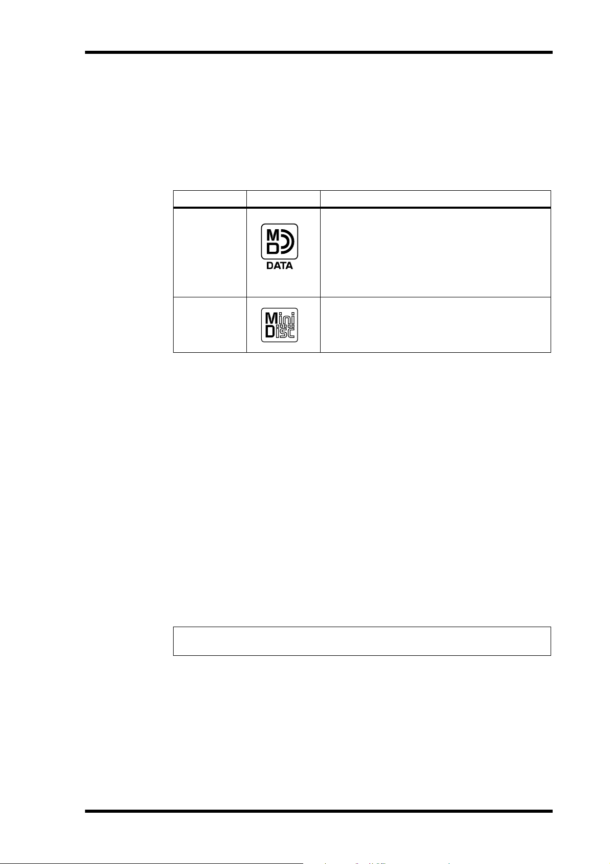
Type Logo Description
MD DATA discs are for computer data storage
applications. You can purchase them at computer stores. This is the type of disc you should
MD DATA
MiniDisc
buy for 8-track recording and playback with your
MD8. Note that there are two types available:
playback only and rewritable . Buy the rewritable
type.
MiniDiscs are used only for music. Two types are
available: playback only and recordable . The MD8
can record up to two tracks on the recordable
type and play the playback only type.
3
New MD D ATA discs do not requir e formatting before use with the MD8. Discs that have
been used to store computer data, however, must first be formatted. See
page 62.
Regular MiniDisc decks cannot play MD DATA discs.
Regular MiniDiscs recor ded on the MD8 can be pla yed on a regular MiniDisc deck.
MiniDisc recordings made on a regular MiniDisc deck can be edit ed on the MD8. MiniDiscs
containing songs that were digitally copied from a c ommer cial CD, how ev er, cannot be
edited due to the SCMS (Serial Copy Management Syst em) pr ot ection syst em.
Erasing Discs on
MD8 TOC
TOC refers to the Table Of Contents area on a disc. The TOC contains information about
what is recorded on the disc, the disc title, song titles, and so on. The TOC EDIT indicator
lights up when the TOC needs to be updated, usually after a new r ecording or edit. You must
update the TOC before ejecting a disc or turning off the MD8. It’ s also a good idea to update
the TOC at regular intervals just in case of a power failure. Failur e t o updat e the TOC can
result in data being lost. For e xample, if you record something but do not updat e the T OC,
your data will be lost if the MD8 is inadvertently turned off, the power cor d accidentally dis-
connected, or a po w er failure occurs.
Note: If you press the EJECT button while TOC EDIT is shown on the display, the disc
will not eject. Press [TOC WRITE] (STOP) to update the TOC, and then eject the disc.
MD8—Owner’s Manual
Page 12
4
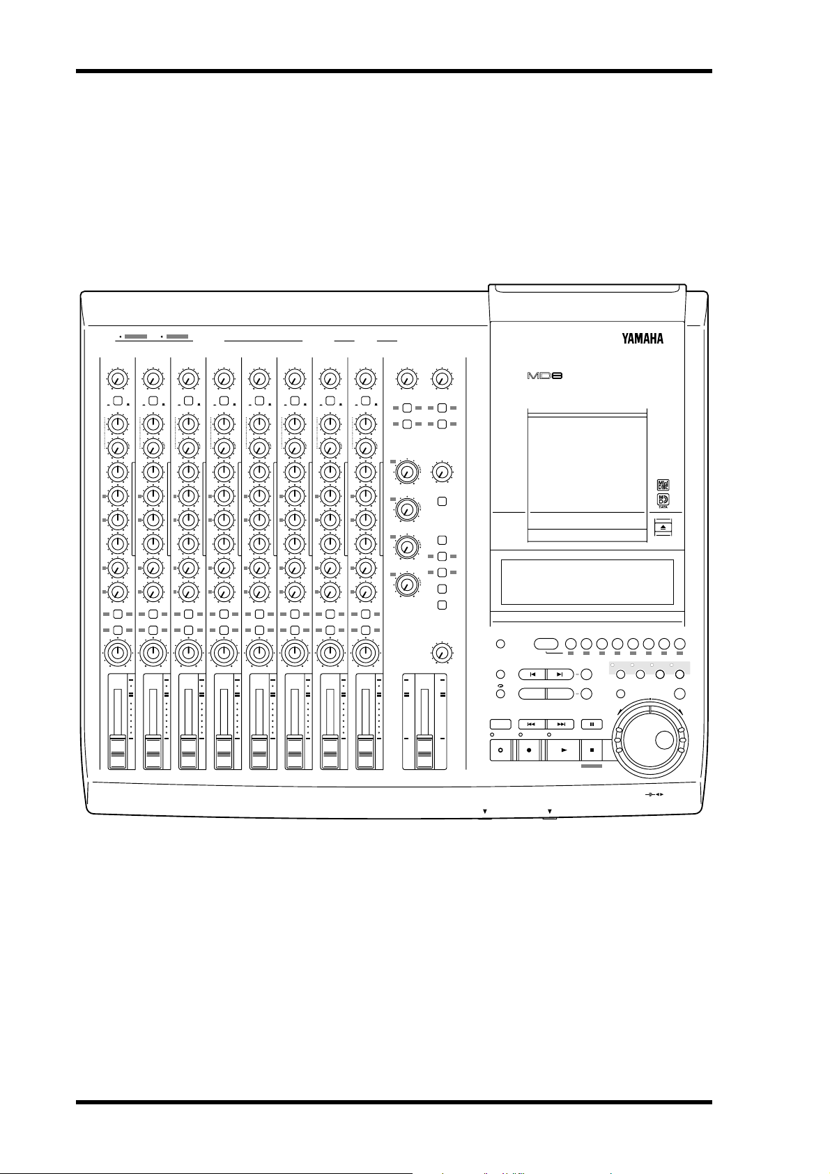
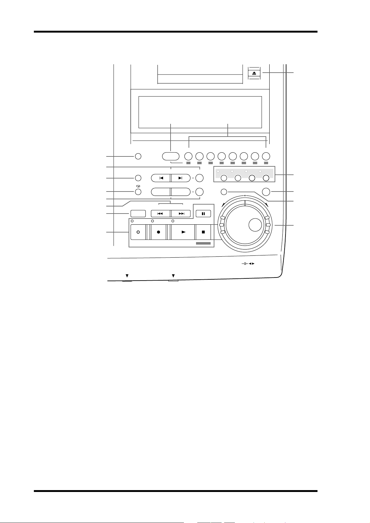
Touring the MD8
2
1 2 345678 9101112 1 2INSERT I/O INSERT I/O
GAIN
LINE
PB MIC/
FLIP
CUE
LR
010
HIGH
–15 +15
MID
F
250 5k
G
–15 +15
LOW
–15 +15
AUX
1
010
2
010
1 2
GROUP ASSIGN
3 4
PAN
L
ODDREVEN
10
9
8
7
6
5
4
3
2
1
0
Touring the MD8
This chapter takes you on a tour of the MD8, identifying the various parts to help you become
familiar with your new recorder.
Topside View
MIC/LINE INPUT LINE INPUT AUX SEND
8
7
6
5
4
3
2
1
GAIN
LINE
MIC
MIC
PB MIC/
LINE
LINE
FLIP
CUE
P
A
N
LR
L
E
V
E
L
010
HIGH
–15 +15
MID
F
250 5k
G
–15 +15
LOW
–15 +15
AUX
1
010
2
010
1 2
GROUP ASSIGN
3 4
PAN
L
ODDREVEN
10
9
8
7
6
5
4
3
2
1
0
GAIN
LINE
PB MIC/
CUE
P
A
N
L
E
V
E
L
HIGH
–15 +15
MID
F
250 5k
G
–15 +15
LOW
–15 +15
AUX
1
2
1 2
GROUP ASSIGN
3 4
PAN
L
ODDREVEN
10
9
8
7
6
5
4
3
2
1
0
MIC
LINE
FLIP
P
A
N
LR
L
E
V
E
L
010
010
010
GAIN
LINE
PB MIC/
FLIP
CUE
LR
010
HIGH
–15 +15
MID
F
250 5k
G
–15 +15
LOW
–15 +15
AUX
1
010
2
010
1 2
GROUP ASSIGN
3 4
PAN
L
ODDREVEN
10
9
8
7
6
5
4
3
2
1
0
MIC
LINE
GAIN
LINE
PB MIC/
CUE
P
A
N
L
E
V
E
L
HIGH
–15 +15
MID
F
250 5k
G
–15 +15
LOW
–15 +15
AUX
1
2
1 2
GROUP ASSIGN
3 4
PAN
L
ODDREVEN
10
9
8
7
6
5
4
3
2
1
0
MIC
LINE
FLIP
P
A
N
LR
L
E
V
E
L
010
010
010
GAIN
LINE
PB MIC/
FLIP
CUE
LR
010
HIGH
–15 +15
MID
F
250 5k
G
–15 +15
LOW
–15 +15
AUX
1
010
2
010
1 2
GROUP ASSIGN
3 4
PAN
L
ODDREVEN
10
9
8
7
6
5
4
3
2
1
0
MIC
LINE
P
A
N
L
E
V
E
L
GAIN
LINE
PB MIC/
FLIP
CUE
LR
010
HIGH
–15 +15
MID
F
250 5k
G
–15 +15
LOW
–15 +15
AUX
1
010
2
010
1 2
GROUP ASSIGN
3 4
PAN
L
ODDREVEN
10
9
8
7
6
5
4
3
2
1
0
MIC
LINE
GAIN
LINE
PB MIC/
CUE
P
A
N
L
E
V
E
L
HIGH
–15 +15
MID
F
250 5k
G
–15 +15
LOW
–15 +15
AUX
1
2
1 2
GROUP ASSIGN
3 4
PAN
ODDREVEN
10
9
8
7
6
5
4
3
2
1
0
FLIP
LR
010
010
010
L
9-10
MIC
010 010
LINE
1
GROUP ASSIGN GROUP ASSIGN
P
A
3 4 3 4
N
L
E
V
E
GROUP
L
MASTER
1
010
2
010
3
010
4
010
2 1 2
10
9
8
7
6
5
4
3
2
1
0
11-12
CUE
MASTER
010
CUE MIX
TO STEREO
MONITOR
SELECT
2TR IN
1 3
GROUP
2 4
STEREO
CUE
MONITOR
LEVEL
MIN MAX
10
9
8
7
6
5
4
3
2
1
0
MULTITRACK MD RECORDER
DISPLAY
REPEAT MARK SEARCH MARK
A B LAST REC SEARCH SET EXIT
AUTO
PUNCH I/O SONG SEARCH PAUSE
REHE REC PLAY STOP
CH 1 CH 2 CH 3 CH 4 CH 5 CH 6 CH 7 CH 8
GROUP 1
IN OUT
2345678
12341234
REC SELECT
ADJUSTPITCH EDIT UTILITY
ENTER
2
1
MD8—Owner’s Manual
8 STEREO
7
6
5
4
3
PHONES PUNCH I/O
The individual sections of the MD8 are explained on the following pages.
TOC WRITE
DATA
CURSOR
+ –
Page 13
1
2
3
4
5
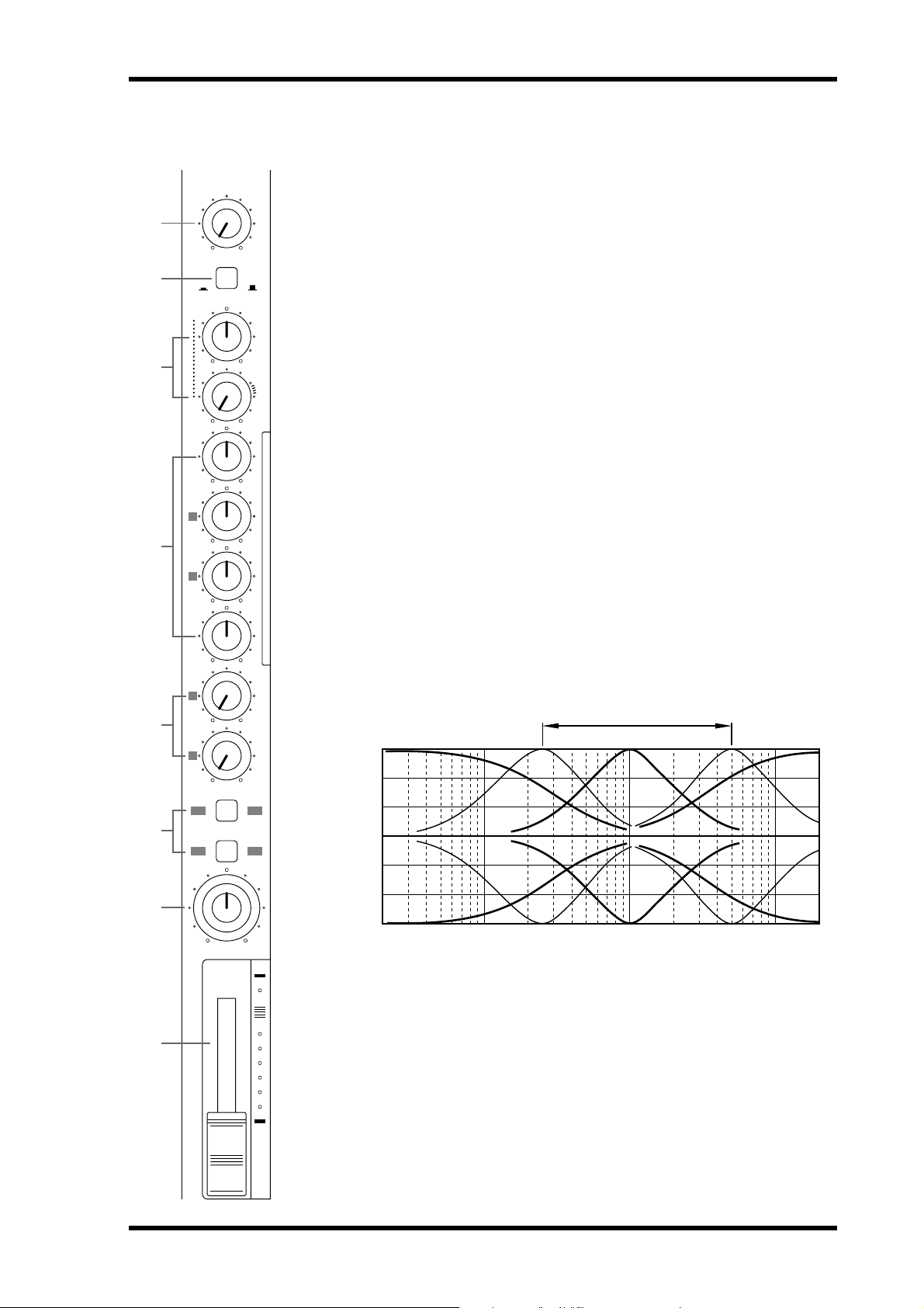
Input Channels
1
GAIN
LINE
PB MIC/
FLIP
CUE
LR
010
HIGH
–15 +15
MID
F
250 5k
G
–15 +15
LOW
–15 +15
AUX
1
010
2
010
MIC
LINE
P
A
N
L
E
V
E
L
A
This rotary control adjusts the sensitivity of the MIC/LINE input so that both
microphone and line-level signals can be handled with ease.
B
This switch is used to select the signal sources for the input channel and CUE controls. With the [FLIP] switch in the up position, the MIC/LINE input signal is
fed to the input channel and the track signal is fed to the CUE controls. With the
[FLIP] switch in the down position, however, this is r ev ersed: the MIC/LINE
input signal is fed to the CUE controls and the track signal is fed to the input
channel.
C
These two controls are used to adjust the lev el and pan of the CUE signal. The
CUE signal source depends on the [FLIP] switch. With the [FLIP] switch set to
the up position, the signal source is the track (i.e., the signal being rec or d ed or
played back). With the [FLIP] switch set to the down position, the CUE signal
source is the MIC/LINE inputs. This setting is typically used during mixdown,
when the track signal is fed through the input channel. This allows you to connect
extra sound sources during mixdown and set their level and pan position using
the CUE controls.
D
These rotary controls are used to boost and cut the high, middle, and low frequency bands independently. The High and Low EQs are fixed frequency shelving
types. The Mid EQ is a sweepable peaking type. A flat setting (i.e., no boost or
cut) can be set quickly using the controls’ center detents.
GAIN control
FLIP switch
CUE PAN & LEVEL controls
EQ controls
+15
+10
Sweepable range
Input Channels
5
6
7
8
1 2
GROUP ASSIGN
3 4
PAN
L
ODDREVEN
10
9
8
7
6
5
4
3
2
1
0
+5
0
–5
Response [dB]
–10
–15
Frequency [Hz]
10k1k100 20k20
HIGH ±15 dB at 12 kHz—shelving type
MID ±15 dB at 250 Hz–5 kHz—sweepable peaking type
LOW ±15 dB at 80 Hz—shelving type
AUX controls
E
These rotary controls are used to send the input channel signal to the A UX SEND
outputs for processing by external effects proc essors.
MD8—Owner’s Manual
Page 14

6
Touring the MD8
GROUP ASSIGN switches
F
These switches are used to assign (i.e., send) the input channel signal to groups. They work
in conjunction with the P AN control. For example, with GROUP ASSIGN switch [1–2] ON
and the P AN co ntrol set midwa y, the channel signal is sent equally to Groups 1 and 2. W ith
the P AN control turned fully counterclockwise (L/ODD), ho wever , the channel signal is sent
only to Group 1. Likewise, when it is set fully clockwise, the signal is sent only to Group 2.
The same principle applies to GROUP ASSIGN switch [3–4]. Note that input channel signals
are always sent to the Ster eo bus r egar dless of the GROUP ASSIGN switch settings.
PAN control
G
This rotary control has two functions: For rec ording it’s used in c onjunction with the
GROUP ASSIGN switches to assign the input channel signal to even and odd numbered
groups. For mixdo wn it’s used to pan (i.e., position) the signal in the ster eo mix.
Fader
H
This fader has two functions: For recor ding it’s used to adjust the level of the input channel
signal that’s r ec or ded t o a track. For mixdown it’ s used t o balanc e the input c hannel signal
relative to the other input channel signals. For optimum performance, faders should be positioned about the 7–8 mark.
MD8—Owner’s Manual
Page 15
1
2
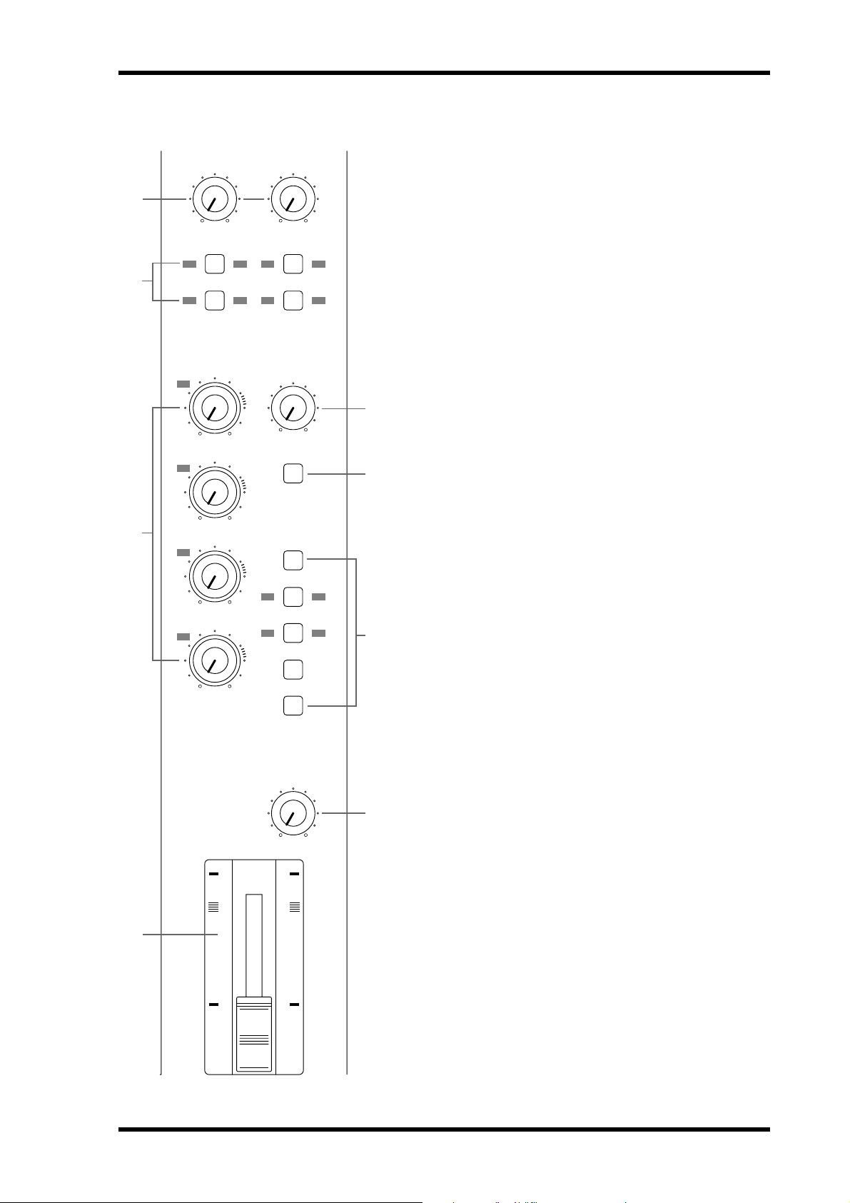
Master Section
9-10
010 010
1
GROUP ASSIGN GROUP ASSIGN
3 4 3 4
GROUP
MASTER
1
010
2
11-12
2 1 2
CUE
MASTER
010
CUE MIX
TO STEREO
Master Section
A
9–10/11–12 input level controls
These rotary controls are used to adjust the level of the 9–10 and
11–12 input signals that are sent to the Stereo bus for mixing.
They’re also used in conjunction with the GROUP ASSIGN
switches to adjust the level of the 9–10 and 11–12 input signals
that are assigned to groups.
B 9–10/11–12 GROUP ASSIGN switches
These switches are used to assign (i.e., send) the 9–10 and 11–12
input signals to the groups. The left-channel signal is sent to odd
Groups 1 and 3, while the right-channel signal is sent to even
Groups 2 and 4. The 9–10 and 11–12 input signals could be the
stereo output signals from another mixer or exte rnal effects processor . Note that the 9–10 and 11–12 input signals are always sent
5
to the Stereo bus for mixing regardless of these switch settings.
C GROUP MASTER level controls
These rotary controls adjust the levels of the group signals that
6
are fed to the tracks.
7
3
4
010
3
010
4
010
10
9
8
7
6
5
4
3
2
1
0
MONITOR
SELECT
2TR IN
1 3
GROUP
2 4
STEREO
CUE
MONITOR
LEVEL
MIN MAX
10
9
8
7
6
5
4
3
2
1
0
D STEREO fader
This fader is used to adjust the level of the stereo signal that is
sent to the STEREO OUT jacks. For optimum performance this
fader should be positioned about the 7–8 mark.
E CUE MASTER level control
This control is used to adjust the overall level of the CUE signal.
7
F CUE MIX TO STEREO switch
This switch is used to feed the CUE bus signals through to the
Stereo bus (i.e., the CUE bus signals are mixed with the
MIC/LINE signals). It’s used for multi-source mixing at mixdown.
G MONITOR SELECT switches
These switches are used to select the signal source for the MONITOR OUT and headphones.
2TR IN—This switch selects the 2TR IN as the monitor source.
8
This allows you to monitor the output of a stereo master
recorder during mixdown.
GROUP—These switches select the Group buses as the monitor source. This allows you to monitor signals assigned to tracks.
When only the [1–3] or [2–4] switch is pressed, the monitor signal is mono. P r ess both switches t o monit or st er eo signals.
STEREO—This switch selects the Stereo bus as the monitor
source. This allows y ou to monitor the STEREO OUT signal and
is typically used during mixdown.
CUE—This switch selects the CUE bus as the monitor source.
This allows you to monitor track signals, which is useful for
punch in/out.
STEREO
H MONITOR LEVEL control
This rotary control adjusts the level of the monitor signal that is
sent to the MONITOR OUT and PHONES connect ors.
MD8—Owner’s Manual
Page 16
8 Touring the MD8
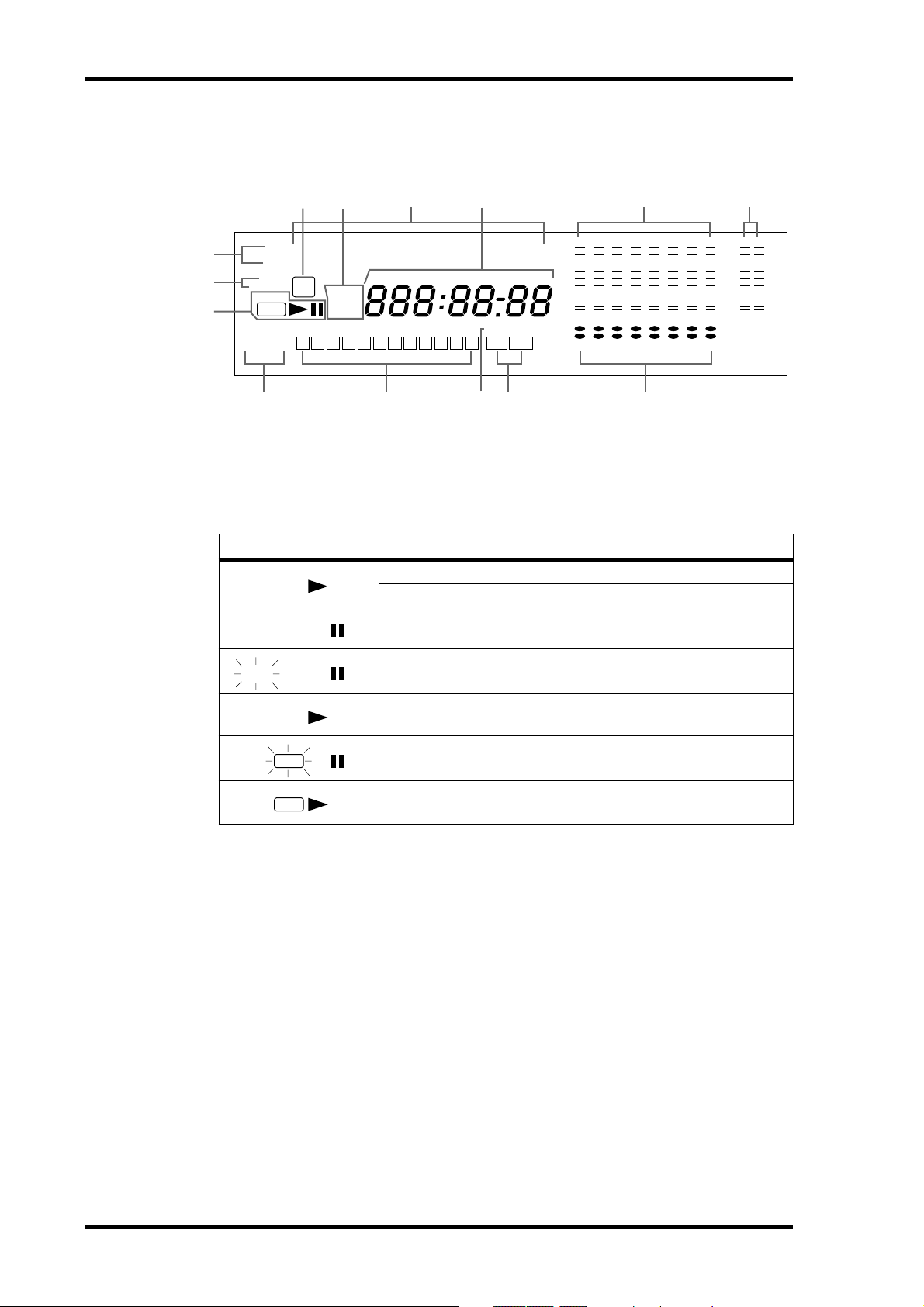
Display
6
MEASURE MIN. BEAT SEC. FRAMES
MARKERS
3
2
1
MTC
MIDI CLK
MMC
PITCH
FIX VARI
REHE
REC
REPEAT
A1ALLB
5
4
MD8 Song
TOC
ELAPSE
EDIT
TOTAL
REMAIN
S 1 2 3 4 5 6 7 8 9 10 E IN OUT
K NMLJ
A Status indicators
These indicators show the current operating mode.
Indicator Meaning
Normal playback
Cue or Review
Playback is paused
7
AUTO PUNCH
8 9
CLIP
–3
–6
–12
–18
–24
–36
DIR
GRP
TRK
1 2 3 4 5 6 7 8
+12
+6
+3
0
–6
–10
–20
dB L R
STEREO
REHE
REHE
REC
REC
Rehearse Pause mode
Rehearsal in progress
Record Pause mode
Recording in progress
B Pitch indicators
These indicators show the current Pitch mode: FIX (fixed) or VARI (variable).
C MTC, MIDI CLK, and MMC indicators
These indicators light when the MIDI synchronization options are used. MT C appears when
the MD8 is generating MIDI Timecode, MIDI Clock appears when it’s generating MIDI
Clock, and MMC appears when the MD8 is set to recei v e MIDI Machine Control commands. Normally, pla yback c ontin ues thr ough all the songs on a disc. When one of these
indicators is lit, howev er , pla yback stops when the end of a song is reached. U se the [SONG
SEARCH] buttons to select other songs.
D TOC EDIT indicator
The TOC EDIT indicator lights when the TOC needs to be updated, usually after a new
recording or edit.
E Time Counter mode
These indicators show the Time Counter mode. When a MIDI tempo map is used, the display shows measure and beat information.
ELAPSE—This mode shows the time position within a song.
MD8—Owner’s Manual
Page 17

Display 9
REMAIN—This mode shows the time remaining for a song or when you are recording a
new song, it shows the available time remaining for the song (on disc).
TOTAL—This mode sho ws the time position within the entire disc.
F Title and function display
Disc titles, song titles, functions, messages, and other information appear here.
G Time counter
The time counter shows the disc time in minutes, seconds, and frames (1/86 second or 1/30
second). When the MIDI t empo map is used, the display sho ws measure and beat information.
H Track level meters
These track level meters show group signal levels in seven steps from –36 dB to CLIP. W ith
no disc loaded, the meters display group signal levels.
I Stereo level meters
These level meters show the STEREO OUT signal levels from –20 dB to +12 dB in seven
steps.
J Repeat mode indicators
These indicators show the Repeat modes.
REPEAT 1—The current song is played repeatedly (One Song Repeat).
REPEAT ALL—All songs are played repeatedly (All Song Repeat).
REPEAT A–B—Pla yback cycles between points A and B (A–B Repeat).
REPEAT Auto Punch I/O—Auto Punch In/Out is rehearsed r epeat edly.
K Markers
These indicators show the status of the Start, End, and 10 markers in between. W hen a song
is recorded, Start and End markers ar e r ecorded automatically. You can also add up to 10
markers per song while recording is in progress or during subsequent playback. When a song
is positioned on or after a marker (stopped, playing, paused, or recording) that mark er
flashes. When the beginning of a song is located, the Start marker flashes. When the end is
located, the End marker flashes.
L AUTO PUNCH indicator
The AUTO PUNCH indicator shows that the AUTO PUNCH In/Out function is on.
M IN & OUT indicators
The IN and OUT indicators light up when the LAST REC IN and OUT points have been
set. W hen a song is positioned on or after the IN or OUT point, the co rresponding indicator
flashes.
IN—This indicator lights up when the LAST REC IN point has been set. W hen the Auto
Punch function is on, it goes off when a song is located on or after the specified IN point.
OUT—This indicator lights up when the LAST REC OUT point has been set. When the A uto
Punch function is on, it goes off when a song is located on or after the specified OUT point.
N Track record indicators
These indicators show which tracks are selected for recor ding. The DIR indicators light up
when the input channel signal is selected for direct recording, and the GRP indicators light
up when the group signal is selected for recording.
MD8—Owner’s Manual
Page 18
10 Touring the MD8
Disc Transport Section
K
J
REC SELECT
ADJUSTPITCH EDIT UTILITY
8
7
9
DISPLAY
GROUP 1
REPEAT MARK SEARCH MARK
CH 1 CH 2 CH 3 CH 4 CH 5 CH 6 CH 7 CH 8
12341234
2345678
6
ENTER
5
4
3
A B LAST REC SEARCH SET EXIT
AUTO
PUNCH I/O SONG SEARCH PAUSE
IN OUT
2
REHE REC PLAY STOP
1
TOC WRITE
DATA
CURSOR
+ –
PHONES PUNCH I/O
A Disc Transport buttons
REHE—This button is used to enter Rehearse mode. The REHE indicators flash in Rehearse
Pause mode and stay on c ontin uously while r ehearsal is in pr ogress.
REC—This button is used to enter Rec ord mode. The REC indicators flash in R ecord P ause
mode and stay on continuously while reco r ding is in pr ogress.
PLAY—This button is used to start normal playback, start rehearsal, and start rec ording. I t
can also be used to cancel rehearsal and recor ding. In this case, normal playback continues
from the point at which the [PLAY] button is pressed. The PLAY indicators light up while
playback is in progress and flash when playback is paused.
PAUSE—This butt on is used t o pause pla yback, recording, or r ehearsal.
STOP/TOC WRITE—This button is used to stop playback, rehearsal, and recording. It’ s
also used to write the TOC data to disc when the MD8 is stopped.
L
M
N
O
B AUTO PUNCH I/O button
C SONG SEARCH buttons
D LAST REC SEARCH IN/OUT & SET buttons
MD8—Owner’s Manual
This button is used to turn on the A u t o P unc h I n/Out function.
These buttons are used to search for songs.
The SET button is used in combination with the LAST REC SEARCH IN/OUT buttons to
set the LAST REC IN/Punch In and OUT/Punch Out points. The LAST REC SEARCH
IN/OUT buttons are used to locate the LAST REC IN and OUT points.
Page 19

Disc Transport Section 11
E A B Repeat buttons
These buttons are used to enter the A and B points for A-B Repeat.
F REPEAT button
This button is used to select the 1 Song, All Song, A-B, and Auto Punch Rehearse Repeat
modes. It’s also used to cancel A-B Repeat mode.
G MARK SEARCH & MARK buttons
The MARK SEARCH buttons are used to locate song markers. The MARK button is used
to enter markers during recording or playback.
H DISPLAY button
This button is used to select the Time Counter mode: ELAPSE, REMAIN, or TOTAL. When
the MIDI tempo map is used, the display sho ws measure and beat information.
I GROUP button
Used in combination with the REC SELECT buttons, this button is used to set tracks to
record group signals.
J REC SELECT buttons
These buttons are used to select tracks for recording. Pressing a REC SELECT butt on on its
own sets the corresponding track to record input channel signals (DIR). Holding do wn the
GROUP button and pressing a REC SELECT button sets the c orresponding track to record
group signals (GRP).
K EJECT button
This button is used to eject the disc.
Note: If you press the EJECT button while T OC EDIT is shown on the display, the disc
will not eject. Press [TOC WRITE] t o updat e the TOC, and then eject the disc.
L Function buttons
PITCH—This button is used to access the Pitch function. Depending on how you set this
function, the FIX (fixed) or VARI (variable) indicator lights (see page 87).
ADJUST—This button is used to adjust the position of markers and the LAST REC IN and
OUT points.
EDIT—This button is used to ac cess the Part Copy , Part Erase, T rack Copy, T rack Erase, Song
Copy , Song Erase, Song Tempo, Song Divide, Song Combn, Song Mo ve, Song Renum, Song
Name, Disc Erase, and Disc Name functions.
UTILITY—This button is used t o ac c ess the following functions: Rec Mode, P r ePost Roll,
Cue List, P rog Play, MIDI Sync, MMC R ec ei ve, MMC Dev ID, Frame Disp, Disp Dimmer,
Peak Hold, and Disc Info.
M ENTER button
This button is used to set functions.
N EXIT button
This button is used to cancel functions and modes.
O CURSOR shuttle/DATA dial
The central dial (called DATA) is used to set and select parameters (+/– DATA). W hen the
MD8 is stopped or paused, the D A T A dial can be used to move thr ough a song in frame steps.
The outer shuttle (CURSOR) is used to select items on the display . When the MD8 is stopped
or paused, the shuttle can be used to mov e thr ough a song at high speed. During playback,
it can be used for cue and review at 0.5x, 2x, 4x, 8x, 16x, or 32x playback speed (0.5x cue
only).
When using cue or review, the time counter may stop occasionally.
MD8—Owner’s Manual
Page 20
12 Touring the MD8
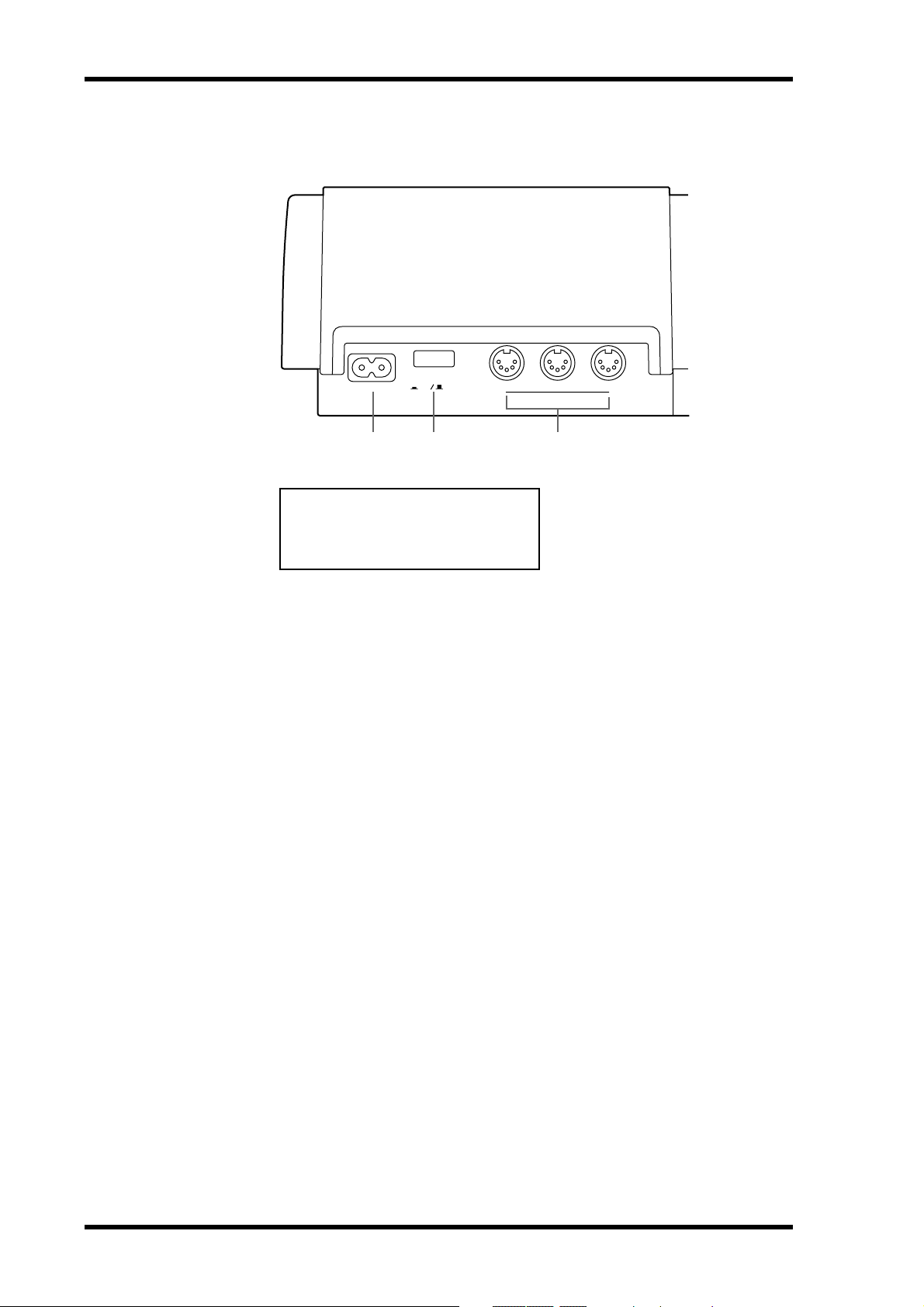
Rear Panel
AC IN THRU OUT
POWER
ON OFF
MIDI
IN
1 2 3
CAUTION
TO PREVENT ELECTRIC SHOCK,
MATCH WIDE BLADE OF PLUG TO
WIDE SLOT, FULLY INSERT.
A AC IN
Connect the supplied power cor d her e.
B POWER ON/OFF switch
This switch is used to turn on and off the MD8.
C MIDI IN, OUT & THRU
The MD8 receives MMC (MIDI Mac hine C ontr ol) c ommands via the MIDI IN port, and
outputs MIDI Clock or MTC (MIDI Timecode) fr om the MIDI OUT port. The MIDI THRU
port outputs MIDI data received at the MIDI IN port.
MD8—Owner’s Manual
Page 21
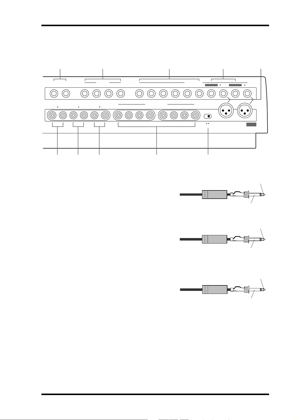
Rear Panel 13
4 5 6 7 8
1 1211109 876543 2
2
MONITOR OUT STEREO OUT
RLRL
9
J K L M
D AUX SEND
These 1/4-inch phone jacks are used to send
the Aux Send signals to e xt ernal effects processors. Connect them to the effects processors’ inputs.
E LINE INPUT 9–10/11–12
These 1/4-inch phone jacks are used to connect unbalanced electronic musical instruments and other line-level sound sources that
have stereo outputs. They can also be used to
return the processed stereo signals from
external effects processors. The pr oc essed
signals can then be mixed into the MD8 stereo mix or recorded to tracks.
LINE INPUTAUX SEND
2TR IN
RL 8765 4321
TRACK DIRECT OUT
MIC/LINE INPUT
INSERT I/O INSERT I/O
21
231
PHANTOM
1/4" phone plug
1/4" phone plug
1: GMD 2: HOT 3: COLD ON OFF
MIC/LINE
IN (BAL)
1
231
DC48V
MAX. 7mA
Tip (send)
Sleeve (ground)
Tip (send)
Sleeve (ground)
F MIC/LINE INPUTs 3–8
These 1/4-inch phone jacks are used to connect unbalanced microphones, electronic
musical instruments, and other line-level
sound sources.
Tip (send)
1/4" phone plug
Sleeve (ground)
MD8—Owner’s Manual
Page 22
14 Touring the MD8
Phono plug
Tip
Sleeve
Phono plug
Tip
Sleeve
Phono plug
Tip
Sleeve
Phono plug
Tip
Sleeve
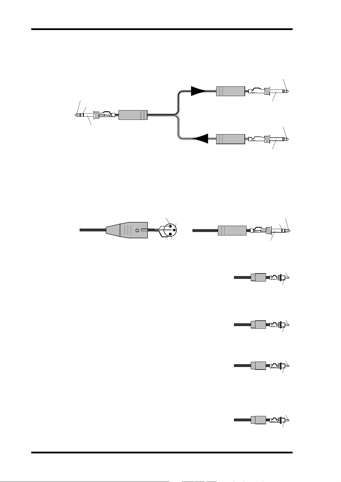
G INSERT I/O
These TRS phone jacks are used to connect signal processors for use with input channel 1
and input channel 2 exclusively. Typically, compressors, limiters, and noise gates are c onnected to this type of connection.
Tip (send)
1/4" phone plug
Tip (send)
Ring (return)
Sleeve (ground)
Connect to INSERT I/O jack
1/4" TRS phone plug
To processor's input
1/4" phone plug
From processor's output
Sleeve (ground)
Sleeve (ground)
H MIC/LINE INPUTs 1 & 2
These inputs are used to connect balanced condenser micr ophones and balanced line-level
signal sources to the MD8 (unbalanced sources can also be c onnected). Each input features
a XLR-type connector and TRS phone jack connector. Phantom power is available on the
XLR-type connector for use with condenser microphones. I f you’re not using condenser
microphones with these inputs, keep the PHANT OM POWER ON/OFF switch set to OFF.
Male XLR plug
1 (ground)
3 (cold)
2 (hot)
1/4" TRS phone plug
Ring (cold)
Sleeve (ground)
I MONITOR OUT
These phono jacks are used to send the monitor signals to a stereo monitor amplifier and speakers. This could be a dedicated
monitor amplifier and speakers or your hi-fi system. Connect
them to the monitor amplifier’ s st er eo inputs. The MONITOR
OUT signal is the same as the headphone signal.
Tip (return)
Tip (hot)
J STEREO OUT
K 2TR IN
L TRACK DIRECT OUTs
MD8—Owner’s Manual
These phono jacks are used to connect a stereo mast er rec order
for recording the final mix. The master record er could be a D AT
deck, MiniDisc deck, or cassette tape deck. Connect them to your
master recorder’s stereo inputs.
These phono jacks are used to connect the outputs of a stereo
master recorder to the MD8. The master recorder could be a D A T
deck, MiniDisc deck, or cassette tape deck. Connect them to your
master recorder’s stereo outputs. To monitor the output of the
stereo master record er during mixdown, pr ess the 2TR IN
MONITOR SELECT switch.
These phono jacks are used to send the track signals to another
mixer . This is useful when you use the MD8 in c onjunction with
a larger mixer. Connect them to the line inputs on the other
mixer. With no disc loaded, the DIRECT OUTs 1–4 output the
signals of Groups 1–4.
Page 23
Front Connectors 15
M PHANTOM POWER ON/OFF switch
This switch is used to turn on and off the phantom power for the XLR-type MIC/LINE (BAL)
inputs on channels 1 and 2. Phantom pow er is used t o po w er condenser microphones. It
should be turned off when devices other than condenser microphones ar e connected to these
inputs.
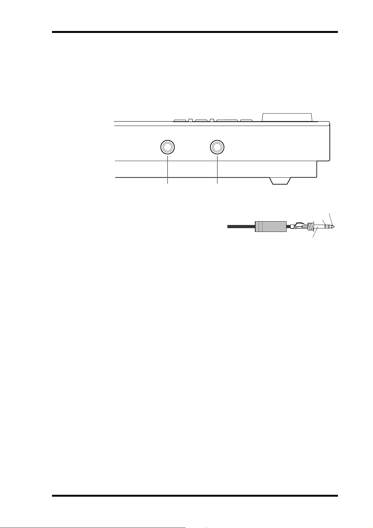
Front Connectors
1 2
A PHONES
A pair of stereo headphones can be connected here for monitoring. The headphone signal is the same as the MONITOR
OUT signal.
1/4" TRS phone plug
Ring (right)
Sleeve (ground)
B PUNCH I/O
An optional footswitch, such as the Yamaha FC5, can be connected here for foot-controlled
playback, rehearsal, recording, or punch in/out.
Tip (left)
MD8—Owner’s Manual
Page 24
16 The First Session
3 The First Session
This chapter explains how to rec ord and mix your first MD8 session. If this is your first time
with a multitrack recorder , we recommend that y ou start with this chapter and follow all the
procedures closely . When you ’ve complet ed this chapter , have a look at subsequent c hapters,
which explain more advanced MD8 functions and require a basic knowledge of MD8 and
multitrack recording techniques.
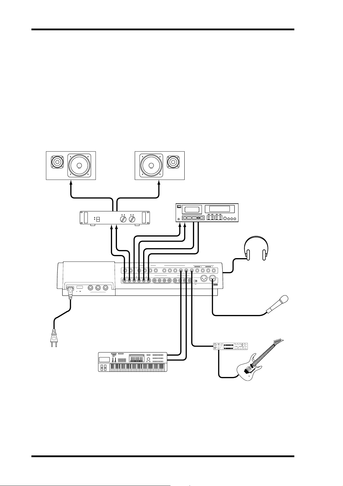
Quick-Start System
The following illustration shows a basic MD8 recording system.
Monitors
AC IN THRU OUT
Connect to an
appropriate
Wall Outlet
Monitor Amp
POWER
ON OFF
MID
Synthesizer
Master Recorder
2
MONITOR OUT STEREO OUT
RLRL
IN
LINE INPUTAUX SEND
1 1211109 876543 2
2TR IN
RL 8765 4321
TRACK DIRECT OUT
MIC/LINE INPUT
INSERT I/O INSERT I/O
PHANTOM
1
MIC/LINE
IN (BAL)
21
231231
1: GMD 2: HOT 3: COLD ON OFF
DC48V
MAX. 7mA
Headphones
Microphone
Guitar Processor
YAMAHA
MD8—Owner’s Manual
The microphone, synthesizer , and guitar are just examples of the kind of sound sources that
can be connected to the MD8. F or monitoring, you can use either headphones or a monit or
amp and speakers. Alt ernati v ely, you could use your hi-fi amp and speakers. The mast er
recorder is only required for mixdo wn.
Page 25

Connecting the Power Cord 17
Connecting the Power Cord
1. Connect the supplied power cord to the AC IN socket on the rear of MD8.
2. Plug the other end of the power cord into a suitable AC wall outlet.
Turning on the MD8
1. Press the POWER switch at the rear of the MD8. The display lights up.
POWER
ON OFF
To turn off the MD8, press the PO WER switch again.
Loading a Disc
1. Press the EJECT button to open the disc compartment.
2. Insert the disc into the compartment with the arrow pointing forward.
The disc should slide easily into the compartment and click into place. If it doesn’t, make
sure you ’ve inserted it the right way around (arro w forward) and into the retaining brack et
(you may hav e to tak e a close look at the disc compartment the first time you insert a disc).
3. Close the disc compartment.
When a disc is loaded, the MD8 reads the TOC to see what the disc contains. If it’s a new
disc, the message
appears for a few seconds and then scrolls off the display . After that, the total number of songs
on the disc is shown. For example,
Blank Disc appears. If the disc contains some songs, the disc title
Total 004 .
Recording the First Track
The conventional method of multitrack recording is to assign input channels t o group buses
that feed signals to the recording device. On the MD8 this is called group r ecording (GRP).
In addition to group recording, the MD8 features direct r ecording (DIR), which allows y ou
to record input channels 1 t o 8 directly to tracks 1 to 8, effectively b ypassing the group buses.
Each method has its pros and cons.
GRP—Use this method to rec ord an input channel to a track other its corresponding track.
For example, t o recor d a balanced condenser micr ophone signal on input channel 1 to , say,
track 7. The GRP method can also be used to mix signals from several input channels and
record them to one or two tracks. For example, to r ecord drum microphone signals on input
channels 1 to 4 to, say , tracks 1 and 2.
DIR—Use this method to rec ord an input channel to its corresponding track without having
to set the GROUP ASSIGN buttons and PAN control. Since the MD8 has only four group
buses, you cannot rec or d more than four signals independently using the GRP method.
Using the DIR method, ho w ev er, y ou can record 5, 6, 7, or 8 independent signals simultaneously, in other words, 8-track simultaneous rec ording.
Both methods are explained in this section.
MD8—Owner’s Manual
Page 26
18 The First Session
Making the Connections (GRP & DIR)
1. Connect a sound source to MIC/LINE INPUT 1.
If you are using a condenser microphone, set PHANTOM switch to ON to turn on phantom
powering.
2. Set the [FLIP] switch on Input Channel 1 to MIC/LINE.
3. If you connect a line-level source, set the GAIN control to LINE (i.e., fully
counterclockwise). If you connect a microphone, set the GAIN control
midway. The GAIN control is adjusted again later on in this procedure.
4. Proceed to GRP Method or DIR Method.
GRP Method
1. Press Input Channel 1’s GROUP ASSIGN [1–2] switch.
This assigns the Channel 1 signal to Tracks 1 and 2.
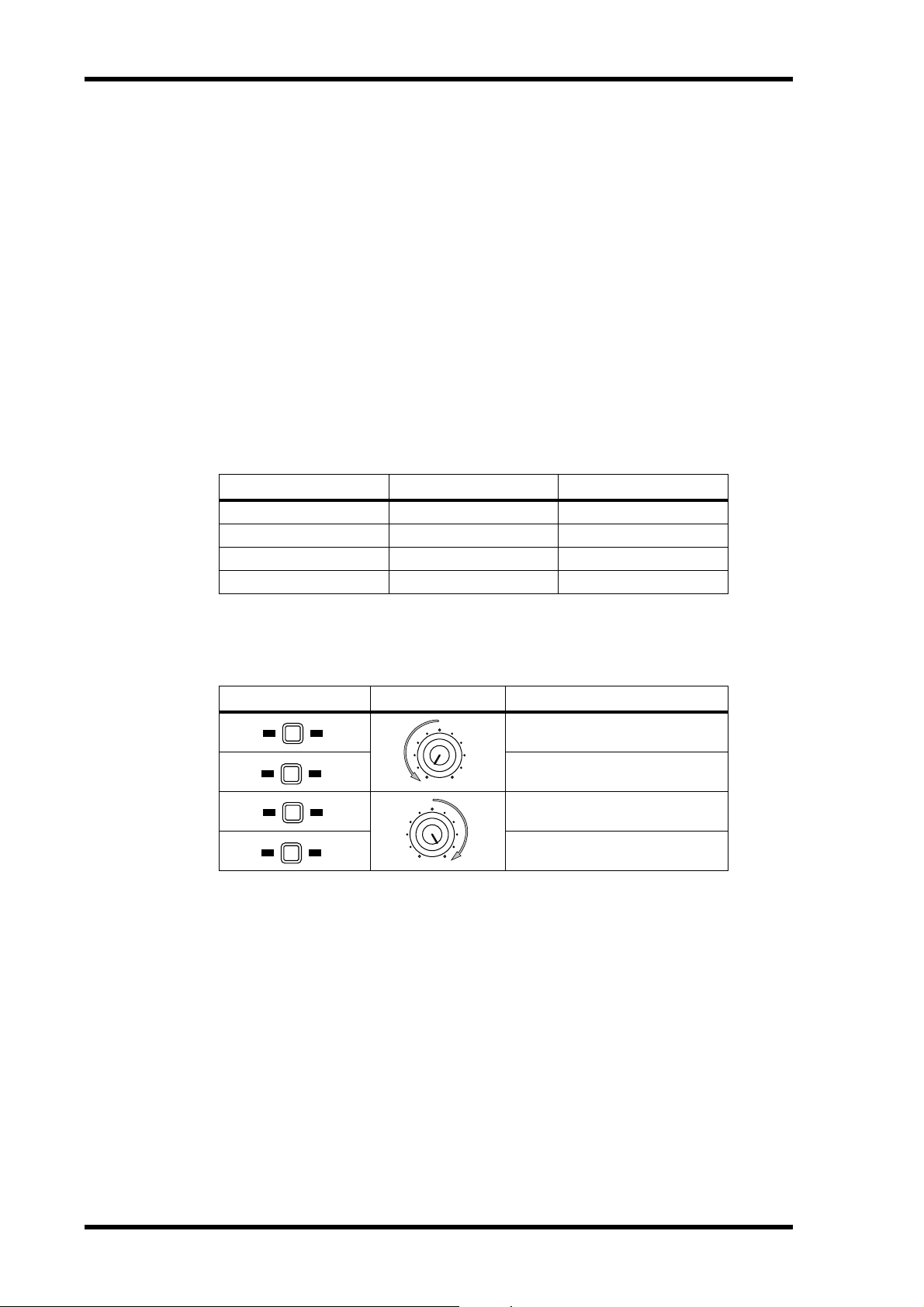
The following table shows the relationship between Groups and Tracks.
Assigned to... Destination Track
Group 1 → Track 1 or 5
Group 2 → Track 2 or 6
Group 3 → Track 3 or 7
Group 4 → Track 4 or 8
2. Turn the PAN control to L/ODD.
This sends the signal to just Track 1.
The following table shows the relationship between the PAN control and groups.
GROUP ASSIGN PAN Destination Group/Track
1 2
3 4
1 2
3 4
L
ODDREVEN
L
ODDREVEN
Group 1
Group 3
Group 2
Group 4
3. While pressing the REC SELECT [GROUP] button, press the REC SELECT
[1] button.
The TRK 1 GRP indicator flashes, indicating that track 1 is set to recor d fr om group Bus 1.
4. Set the GROUP MASTER 1 level control to the 7–8 mark (highlighted position).
5. Proceed to Monitoring & Recording (GRP & DIR).
MD8—Owner’s Manual
Page 27

Recording the First Track 19
DIR Method
1. Press the REC SELECT [1] button.
The TRK 1 DIR indicator flashes, indicating that track 1 is set to record directly fr om input
channel 1.
2. Proceed to Monitoring & Recording (GRP & DIR).
Monitoring & Recording (GRP & DIR)
1. Press the MONITOR SELECT [CUE] switch.
2. Set the MONITOR LEVEL control midway.
3. Set the CUE MASTER control midway.
4. Set Channel 1’s CUE LEVEL control to the to the 7–8 mark.
5. Raise Channel 1’s fader to the 7–8 mark.
6. Press the [REC] button.
You should now be able to hear the sound source and see the signal level on track 1 meter.
If you don’t hear anything, recheck the preceding steps.
The REC indicators flash, indicating Rec o r d Pause mode.
7. Adjust Channel 1’s GAIN control so that the loudest sounds cause the
meter to reach the –3 position. If the meter goes beyond the –3 position
into CLIP, back off the GAIN control a little.
It is important that you set this level correctly to achieve the best sound. Too low a level does
not make full use of the sonic capabilities of your MD8. T oo high a level may cause distortion.
Tip: If the level of the sound source varies greatly, making it difficult to find an optimum
setting for the GAIN control, y ou can use an e xte rnal co mpr essor t o ev en out the signal
level. A c ompressor can be patched directly into channel 1 or 2 using INSER T I/O.
The MD8 is now ready to rec or d. All you hav e t o do t o start reco r ding is pr ess the [PLAY]
button. So make sur e that your music source is ready to go. If you want to cancel Recor d
Pause mode, pr ess the [STOP] button.
8. Press the [PLAY] button to start recording.
Recording starts and the time counter sho ws the r ec ording time.
9. Press the [STOP] button to stop recording.
You’ve now recorded your first track.
Listening to the First Track
1. Press the LAST REC SEARCH [IN] button.
This returns to the point at which recording started. For the first recording, this is al ways
00:00.00.
2. Press the [PLAY] button to start playback.
Y ou should no w be able to hear what was recorded. A djust CUE LEVEL 1 as required. If you
don’ t hear anything, recheck the preceding steps.
MD8—Owner’s Manual
Page 28

20 The First Session
Overdubbing
Overdubbing is the technique used to rec ord new sounds to empty tracks while listening to
the sounds already recorded on other tracks. The follo wing over dubbing proc edure can be
used to record to Tracks 2–8, and you can use the GRP or DIR method, the latter method is
used in this procedure.
1. On the input channel previously used for recording, set the fader to zero,
and set the GROUP ASSIGN switches to OFF.
2. Press the REC SELECT [1] button so as not to overwrite that track.
The flashing dot disappears.
3. Press the LAST REC SEARCH [IN] button.
This returns to the point at which recording started.
4. Connect a sound source to MIC/LINE INPUT 2–8.
5. If you connect a line-level source, set the GAIN control to LINE (i.e., fully
counterclockwise). If you connect a microphone, set the GAIN control
midway. The GAIN control is adjusted again later on in this procedure.
6. Set the [FLIP] switch to MIC/LINE.
7. Set the channel’s CUE LEVEL control to the to the 7–8 mark.
8. Raise the Channel’s fader to the 7–8 mark.
9. Press the [REC SELECT] button of the track that you want to record.
The DIR indicator for that channel flashes.
10. Press the [REC] button.
The REC indicators flash, indicating Rec ord P ause mode. The track meter sho ws the signal
level, and you should be able to hear the signal sour c e.
Note: You could press the [REHE] button instead to rehearse the o verdub.
11. Adjust the GAIN control on the input channel so that the loudest sounds
cause the meter to reach the –3 position. If the meter goes beyond the
–3 position into CLIP, back off the GAIN control a little.
12. Press the [PLAY] button to start recording (or Rehearsal).
Recording (or R ehearsal) starts and the time count er sho ws the r ecording time.
13. Use the input channel CUE LEVEL controls to balance levels with the
tracks already recorded.
14. Press the [STOP] button to stop recording (or Rehearsal).
15. Press the LAST REC SEARCH [IN] button.
This returns to the point at which recording (or Rehearsal) started.
16. Press the [PLAY] button to play back what you‘ve recorded.
MD8—Owner’s Manual
If you just rehearsed the overdub , there won ’t be anything to play back yet.
Repeat this procedure until you’ve r ec o r ded all tracks. Then you’re ready for mixdown.
Page 29

Mixdown 21
Mixdown
Mixdown is the final technique in multitrack recording. Here you mix the sounds from all
eight tracks, with EQ and effects to create a balanced stereo signal that is recor ded to a stereo
master recorder, such as a DAT, MiniDisc, or cassett e tape deck.
1. Make sure that all [GROUP ASSIGN] switches are off, including the
MONITOR SELECT [GROUP] switches.
2. Turn off the MONITOR SELECT [CUE] switch.
3. Set the [FLIP] switch on each input channel to PB.
4. Set the PAN control on each input channel to its center position.
5. Set the fader on each input channel and the STEREO fader to the 7–8
mark.
6. Press the MONITOR SELECT [STEREO] switch and set the MONITOR
LEVEL control midway.
7. Use the Song Search buttons to locate the start of the song.
If the LAST REC IN point is still 00:00, you can use the LAST REC SEARCH [IN] button.
Alternatively, you can use the MARK SEAR CH butt ons.
8. Press the [PLAY] button to start playback.
You should now be able to hear all your tracks. If you don’t hear an ything, r echeck the pr eceding steps.
9. Mix and refine your music as follows:
Balancing Levels—Use the input channel faders to balanc e the levels of the eight tracks.
Pan—Use the PAN controls to position sounds between the left and right speakers.
EQ—Use the three-band EQ to shape the to ne of each track.
Applying Effects—Use the AUX 1/2 and LINE INPUTs 9–10 and 11–12 to patc h in an
external effects processor. See A pplying Effects on page 48 for more information.
See Mixdown on page 88 for a more detailed look at mixdown techniques.
10. Record the Final Mix to your stereo master recorder.
That’ s it! You’ve completed your first session with the MD8.
MD8—Owner’s Manual
Page 30

22 The First Session
An Overview of Multitrack Recording
This section describes the fundamental principles of multitrack recording.
Basic Multitracking
Monitoring—This is the process of listening to a sound as it’ s being rec orded or listening
to recorded sounds as new sounds are recorded to other tracks. See About Monitoring on
page 23 for more information.
Recording the first track—The first track to be recorded is typically the drum track. A
drum track that starts before other instruments makes a good timing and count-in reference.
If your song starts with several instruments on the first bar, you ma y find it helpful to record
a temporary count-in on another track, which can be erased later. See Recording the First
Track on page 17 for more information.
Overdubbing—This is the technique of recording new sounds to empty tracks while listening to the sounds that you ’ ve alr eady rec orded on the other tracks. Essentially, songs are
recorded track-by-track. This technique is used for most modern studio r ecording. See Over-
dubbing on page 20 for more information.
Mixdown—This is the final stage in multitrack recording. He re you mix the sounds fr om
all eight tracks, with EQ and effects, into a balanced stereo mix and r ecord it to a stereo master
recorder, such as a DAT, MiniDisc, or cassett e tape mac hine. See Mixdown on page 21 for
more information.
Advanced Multitracking
One-Take recording—With this technique, all tracks are r ec orded in one take. This is
useful for live recording and bands that lik e to record with all members playing together . U se
DIR recording method to rec ord up to 8 tracks simultaneously. Punch in/out and ping-pong
techniques can be used after the one-take rec or ding t o add and c o rrect sections. See
One-Take Recor ding on page 83 for mor e information.
Punch In/Out—This technique allows you to r erecord specific sections of a track. It’ s often
used to rerecord a not-so-perfect guitar solo or v ocal phrase. Punc h in/out can be rehearsed
before actually recording to disc. P unch in/out on the MD8 can be performed manually or
automatically, which is useful when you are playing or singing and operating the MD8 all
at the same time. You can use either the DIR or GRP method for punch in/out recording.
See Manual Punch In/Out on page 29 for more information.
Ping-Pong—This technique allows you to mix and r ec or d sev eral tracks onto another
track. This is often used to free up tracks for more rec ording. So although the MD8 is an
eight-track recorder , you can record more than just eight parts using the ping-pong technique. You can also combine ping-pong with overdub recording. For e xample, Tracks 1 and
2 are mixed and recorded onto Track 4 along with a new signal coming from Input
Channel 3. Ping-P o ng can be r ehearsed befor e actually r ecording to disc. Use the GRP
recording method for ping-pong. See Ping-P ong Recording on page 41 for more information.
Synchronization—This technique enables the MD8 and a MIDI sequencer to work
together as a unified recording tool: the MD8 for ac oustic sounds and the MIDI sequence r
for MIDI instrument sounds. See The MD8 & MIDI on page 73 for more information.
MD8—Owner’s Manual
Page 31

About Monitoring 23
About Monitoring
The MD8 features a flexible monitoring system, allo wing you to monitor signals at various
points. You can monitor sounds through a pair of stereo headphones connected to the
PHONES jack, or through a monitor amplifier and speakers c o nnect ed t o the MONITOR
OUT jacks. The MONITOR SELECT switches ar e used t o select the monit or sour c e, and
the MONITOR LEVEL contr ol is used t o adjust the lev el.
2TR IN—This switch selects the 2TR IN connection as the monitor source. This allows you
to monitor signals from a stereo master rec ord er connect ed to the STEREO OUT and 2TR
IN. Selecting [2TR IN] during mixdown allows you to monit or the output of a master
recorder so you can mak e sure that the master recorder is receiving the signals correctly.
GROUP—These switches select the Group buses as the monitor source. This allows y ou to
monitor signals that are assigned from inputs 1 to 12. Use these switches to monitor what
will be recorded. F or e xample, if you’r e r ec or ding the sounds fr om thr ee input c hannels t o
one track simultaneously, you’ll need to list en to a mix of the three sounds in order to balance
the levels correctly. You can do this using the GROUP switches.
When only the [1–3] or [2–4] MONITOR SELECT GR OUP switch is pressed, the monitor
signal is set as mono. This ensures that the signal being monitor ed appears in both the left
and right monitor speakers. So even when you monit or a single group signal, it will be heard
through both speakers. When both the [1–3] and [2–4] MONITOR SELECT GROUP
switches are pressed, ho wever, the monitor signal is set as stereo . So you can monit or stereo
signals on Groups 1 and 2 or Groups 3 and 4.
STEREO—This switch selects the Stereo bus as the monitor source. This allows you to monitor the STEREO OUT signals and is typically used during mixdown. It can also be used to
monitor signals that are not going to be recorded b y the MD8, such as a MIDI tone generator
that is controlled by a MIDI sequencer. In this case, the tone generator is only monitored
while other sounds are recorded on the MD8. Then for the final mixdown, the tone generator
sounds are mixed with the sounds recorded on the MD8 and mix ed down to a stereo master
recorder.
CUE—This switch selects the CUE bus as the monitor source. This allo ws you to monitor
track signals. Unlike the other monit or sources, the CUE monitor sourc e changes when the
MD8 starts recording or rehearsing. F or example, during normal playback CUE allows you
to monitor the sounds recorded on disc. Obviously, if nothing is record ed, there’s nothing
to monitor . W hen either rec ord or rehearse is started, howev er , CUE allows y ou to monitor
the sounds that are assigned to tracks for recording. The application of this may not appear
very obvious at the moment, but all will become clear in the punch in/out and ping-pong
recording sections.
Note: Although you can monitor GR OUP, STEREO , and CUE all at the same time, ther e
is a possibility that you’ll monitor the same signal from tw o differ ent points in the signal
flow. At first, you may find it less confusing to select just one monitor source at a time.
MD8—Owner’s Manual
Page 32

24 The First Session
Multi-Source Mixing
In addition to the eight disc tracks, you can also connect ex te rnal sound sourc es t o the
MIC/LINE inputs and mix up to eight more sound sources with the disc tracks. These extra
sound sources are mixed using the CUE LE VEL and P AN controls. The [CUE MIX TO STEREO] switch makes this possible. When this switch is in the ON position, the CUE bus signals
are sent to the Stereo bus for mixing with the MIC/LINE signals.
In combination with the eight disc tracks and LINE INPUT s 9–12, this means that up to 20
inputs are available for mixdown. Typically, these extra sound sources could be MIDI t one
generators, synthesizers, samplers, etc., that are being co ntrolled by a MIDI sequencer.
The following procedure is similar to the previous mixdown procedur e e xcept that it
explains how to use the CUE controls t o mix the disc signals and MIC/LINE signals.
1. Make sure that all [GROUP ASSIGN] switches are off, including the
MONITOR SELECT [CUE] switch.
2. Use the [FLIP] switch on each input channel to feed the disc and MIC/LINE
signals to the input channel or CUE controls.
With the [FLIP] switch in the up position, the MIC/LINE input signal is fed to the input
channel and the disc signal is fed to the CUE controls. With the [FLIP] switch in the down
position, however, this is reversed: the MIC/LINE input signal is fed to the CUE controls
and the disc signal is fed to the input channel. As the CUE c ontrols c onsist of just level and
pan, signals that require EQ and effects should be fed to the input channel.
1
GAIN
LINE MIC
PB MIC/
FLIP
CUE
LR
010
HIGH
–15 +15
MID
F
250 5k
G
–15 +15
LOW
–15 +15
AUX
1
010
2
010
1 2
GROUP ASSIGN
3 4
PAN
L
ODDREVEN
10
9
8
7
6
5
4
3
2
1
0
1
GAIN
LINE MIC
LINE
P
A
N
L
E
V
E
L
Up (MIC/LINE)
Track 1 (disc)
Input 1 (jack/XLR)
PB MIC/
FLIP
CUE
LR
010
HIGH
–15 +15
MID
F
250 5k
G
–15 +15
LOW
–15 +15
AUX
1
010
2
010
1 2
GROUP ASSIGN
3 4
PAN
L
ODDREVEN
10
9
8
7
6
5
4
3
2
1
0
LINE
P
A
N
L
E
V
E
L
Down (PB)
Input 1 (jack/XLR)
Track 1 (disc)
3. Set the PAN and CUE P AN controls on each input channel to their center
MD8—Owner’s Manual
positions.
Page 33

Multi-Source Mixing 25
4. Set the input channel and STEREO faders to the 7–8 mark, and set the
CUE LEVEL controls midway.
5. Set the [CUE MIX TO STEREO] switch to ON.
6. Press the MONITOR SELECT [STEREO] switch and set the MONITOR
LEVEL control to an appropriate level.
7. Set the STEREO fader to the 7–8 mark.
8. Press the SONG SEARCH [ ] button to return to the 00:00 position.
9. Press the [PLAY] button to start playback.
You can now mix the disc and MIC/LINE signals.
10. Mix and refine your music as described on page 21.
You cannot use EQ and effects with the signals that are assigned to the CUE controls. You
could, how ever, connect an external equalizer or effects pr ocessor between the sound source
and the MD8 input. If you are using the MIC/LINE inputs to co nnect MIDI-c ontr olled
instruments, such as tone generators, synthesizers, and samplers, you can use the EQ and
effects functions built into these devices.
11. Record the final mix to your stereo master recorder.
MD8—Owner’s Manual
Page 34

26 Recording & Mixing Techniques
4 Recording & Mixing Techniques
This chapter explains MD8 recording and mixing t ec hniques.
Recording a New Song
The NEW REC function is used to record new songs on a disc. Songs ar e r eco rd ed sequentially, as shown below. With a blank disc, simply pressing the [REC] button engages New
Record mode. For a disc that already contains some songs, ho w ev er, y ou m ust first locat e
the
Blank area of the disc, as explained below . If there is only one Blank area, it will be called
Blank 1 .
Song 1 Song 2 Song 3 Blank Area
Blank
Though a disc can contain up to 128 blank areas, ther e will only be one (Blank 1) as long as
you do not erase or move previously recorded songs. If you do, the spac e they used to occupy
will be called Blank 2, Blank 3, and so on. That space can then be used for r ec or ding a new
song.
To extend a song it must be followed by a blank area. If songs are contiguous, you may ha ve
to move a song (see page 65) to creat e a blank ar ea follo wing the song y ou wish to exte nd.
Note: Moving a song that’s only a few seconds in length may not e xte nd the blank ar ea.
This is a limitation of the MD disc format.
Song Move
Song 1 Song 2
Song 1 Song 2Song 3 Blank Area
Song 1
When extending a song, NEW REC appears on the display when recording extended int o
the blank area. Y ou can use the REMAIN Time C ounter mode to check how much rec ording
time, including the blank area, is available. For rehearsal, the MD8 always stops at the end
of a song.
A new song cannot be longer than the blank area you recor d it to . If there is more than one
blank on your disc, be sure t o select the longest one.
Blank
Blank
Song 1 can be extended
Song 3 Blank Area
Song 2
Song 2Song 3 Blank Area
Searching for Blanks
MD8—Owner’s Manual
“Blank X” (X represents a number) is the top part of an unrecorded area on a disc. To locate
the blank, press the SONG SEAR CH [ ] button repeatedly until Blank X appears on the
display. Once the desired blank is located, the MD8 is ready to record a new song.
Since nothing is recorded in the blank ar ea, y ou cannot use the Play , Review , and CUE functions. Press the [ ] SONG SEARCH button if you want to return to the previous song.
Page 35

Recording a New Song 27
Setting the Recording Mode
The following table shows the four MD8 Recording modes. Songs on the same disc can be
recorded in different modes, but you cannot change the mode during or after recording.
These modes allow you to use disc space efficiently. Audio quality is the same for all four
modes.
Rec Mode Tracks Used
8TR
4TR 1, 2, 3, 4 37 O X
2TR 1, 2 74 O O
MONO 1 148 O O
1, 2, 3, 4, 5,
6, 7, 8
Recording Time
(minutes)
18 O X
MD DATA
Disc
MiniDisc
O= supported, X= not supported
Normal MiniDisc decks cannot play MD8 MD DATA discs. They can, howev e r, pla y M ini-
Discs containing 2TR and MONO mode songs. Also, an MD4 cannot play back 8TR data
recorded on an MD8. The MD8, however, is capable of playing back MD4 4TR data. Not e
that you can conv ert an 8-track MD8 song to a 4-track song an MD4 can read. See Copying
& Converting Songs on page 62 for more information.
When using a recor dable MiniDisc with the MD8, the 2TR Recor ding mode is selected automatically. For subsequent 8-track recording onto an MD D A T A disc, set the R ecording mode
to 8TR. The Rec o r ding mode setting is st or ed when the MD8 is turned off.
1. T o set the Recording mode, press the [UTILITY] button and use the DAT A
dial to select the Rec Mode function.
2. Press the [ENTER] button.
The display shows 8TR Mode (2TR Mode if you inserted a MiniDisc).
3. Use the DATA dial to select a Recording mode.
The display will indicate the number of tracks available in the selected mode (e.g. “1” when
you select
MONO Mode , “1, 2” for 2TR Mode , etc.). Only the 2TR and MONO modes can
be selected when a MiniDisc is loaded.
4. Press the [ENTER] button.
5. Press the [EXIT] or [UTILITY] button to exit the Rec Mode function and
the Utility mode.
MD8—Owner’s Manual
Page 36

28 Recording & Mixing Techniques
Recording
1. Press the [REC] button to engage Record Pause mode.
The display shows the number of the new song and NEWXREC. This is R ecor d Pause mode.
Initially , all tracks that can be recorded in the current R ecording mode are selected, as shown
by the flashing dots. You cannot deselect all tracks for a new recording. A t least one track is
always selected.
Note: You cannot rehearse when recording in a blank area.
2. Use the REC SELECT buttons to select tracks for recording.
Alternatively , you can hold down the REC SELECT [GR OUP] button while pressing a REC
SELECT button to use the GRP recording method. See R ecording the First Track on page 17
for more information. You can check the available recording time using the REMAIN Time
Counter mode. Press the [DISPLAY] button repeatedly until REMAIN appears on the display.
Note: The REMAIN display alwa ys refers to the a vailable reco rding time in the currently
selected recording mode.
3. Press the [PLAY] button to start recording.
Recording starts and the Time Count er starts counting.
4. When you’ve finished, press the [STOP] button.
Recording stops. Recording stops aut omatically when all available disc space is used up.
5. Press the [TOC WRITE] (STOP) button to update the TOC.
The TOC is updated.
Titling Discs & Songs
When a disc with a title is first loaded into the MD8, the title appears on the displa y for a
few seconds and then scrolls off to the left. When a song with a title is selected, the title
appears on the display next to the song number. Titles mak e it easy t o identify discs and
songs.
1. Press the [EDIT] button and use the CURSOR shuttle/DATA dial to select
the Song Name or Disc Name function.
2. Press the [ENTER] button.
3. Use the CURSOR shuttle to move the cursor to the desired position.
Turning the CURSOR shuttle to the right moves the cursor to the second, third, etc. character . Turn it to the left to move the cursor backward.
4. Use the DATA dial to set characters.
The following characters are available.
ABCDEFGHIJKLMNOPQRSTUVWXYZ
abcdefghijklmnopqrstuvwxyz
()<>:;*+-=/,.,"Ù%$&!?#
0123456789
5. When you’ve finished, press the [TOC WRITE] (STOP) button to update
MD8—Owner’s Manual
Spaces are available between character r ows.
the TOC.
Page 37

Manual Punch In/Out 29
Manual Punch In/Out
The Punch In/Out technique allows y ou to r erecor d specific sections of a track. This can be
used to correct mistakes or rec or d something new int o silent sections of a track. If you’re
operating the MD8 and playing or singing the part to be recorded, y ou’ll find it m uch easier
to use the A uto Punch In/Out function, which performs the punch in/out automatically. See
Auto Punch I n/Out on page 32 for mor e information.
Manual punch in/out can be performed in three different ways: 1) using the [REC] button.
2) using the individual [REC SELECT] buttons. 3) using an optional footswitch. The
Rehearsal function can be used with all three methods.
Using the REC Button
1. Locate to a position before the point at which you want to punch in.
2. Press the [REC SELECT] button (or [GROUP] + [REC SELECT]) of the track
that you want to record.
See Recording the First Track on page 17 for more information.
A dot flashes above the corresponding track indicator (DIR or GRP).
3. Press the [PLAY] button to start playback.
Playback starts and the PLAY indicators light up.
4. At the point where you want to punch in, press the [REC] button.
Recording starts. The REC indicat ors light up . The dot stops flashing and lights up continuously. And the LAST REC IN indicator lights up, indicating that the IN point has been
stored.
If you’re monitoring the track via CUE, you’ll hear the e xisting sound playback until the
[REC] button is pressed, after which you’ll hear the new sound that’s being recorded.
Instead of pressing the [REC] button you could hav e pressed the [REHE] button t o engage
Rehearse mode. R ehearse allows you to hav e a dry run before actually recording. In Re hearse
mode, the REHE indicators light up, not the REC indicators.
5. At the point where you want to punch out, press the [PLAY] button.
Recording stops. The REC indicators go off. The dot above the track indicator flashes, and
the LAST REC OUT indicator lights up, indicating that the OUT point has been stor ed.
Through the CUE monitor you’ll hear the existing sound playback.
6. Press the [STOP] button to stop playback.
The following illustration shows how punch in/out works with the [REC] button.
Out Point
PlayRecord
REC
SELECT
In Point
8
7
6
5
4
3
2
1
Play
RECPLAY STOPPLAY
MD8—Owner’s Manual
Page 38

30 Recording & Mixing Techniques
Using the REC SELECT buttons
1. Locate to a position before the point at which you want to punch in.
2. Make sure that all REC indicators are off (i.e., no tracks selected).
3. Press the [REC] button.
The REC indicators (i.e., the indicator of the [REC] button and the REC message on the display) flash, indicating R ec o r d Pause mode is engaged.
Instead of pressing the [REC] button you could hav e pressed the [REHE] button t o engage
Rehearse Pause mode. R ehearse allows y ou to hav e a dry run before actually recording. The
rest of this procedure can be used with the Rehearsal function. Inst ead of the REC indicators,
however, the REHE indicators are used.
4. Press the [PLAY] button to start playback.
Playback starts and the PLA Y indicators light up. The REC indicators continue to flash, indicating Play Recor d Wait mode.
5. At the point where you want to punch in, press a [REC SELECT] button
(or [GROUP] + [REC SELECT]).
Recording starts. The indicat or of the [REC] button and the REC message on the display
stop flashing and light up continuously. A dot appears abov e the c orresponding track indicator . And the LAST REC IN indicator lights up, indicating that the IN point has been stored.
If you’re monitoring the track via CUE, you’ll hear the e xisting sounds playback until the
[REC SELECT] button is pressed, after which you’ll hear the new sound that’s being
recorded.
6. At the point where you want to punch out, press the [PLAY] button.
Recording stops. The REC indicators go off. The dot above the select ed track indicator
flashes. And the LAST REC OUT indicat or lights up, indicating that the OUT point has been
stored.
Through the CUE monitor you’ll hear the existing sounds playback.
Instead of pressing the [PLA Y] button y ou could have pressed the [REC SELECT] butt on to
punch out. In this case the MD8 remains in Play Record Wait mode, so you can punch in
again using the [REC SELECT] buttons.
7. Press the [STOP] button to stop playback.
The following illustration shows how punch in/out works with the [REC SELECT] buttons.
Out Point
PlayRecord
REC
SELECT
In Point
8
7
6
5
4
3
2
1
REC PLAY STOPPLAY
Play Record
Wait
REC SELECT
3
MD8—Owner’s Manual
Page 39

Manual Punch In/Out 31
Using a Footswitch
1. Connect an optional footswitch to the PUNCH I/O jack (front panel).
2. Locate to a position before the point at which you want to punch in.
3. Press the [REC SELECT] button (or [GROUP] + [REC SELECT]) of the track
that you want to record.
A dot flashes above the corresponding track indicator.
4. Press the [REC] button.
The REC indicators flash, indicating Rec o r d Pause mode is engaged.
5. Press the footswitch to start playback.
Playback starts and the PLAY indicators light up. The REC indicat ors c o ntinue t o flash.
6. At the point where you want to punch in, press the footswitch again.
Recording starts. The REC indicat ors light up. The dot abo ve the track indicator stops flashing and lights up continuously . And the LAST REC IN indicator lights up, indicating that
the IN point has been stored.
If you’re monitoring the track via CUE, you’ll hear the e xisting sounds playback until the
footswitch is pressed. A ft er which you’ll hear the new sound that’s being recorded.
7. At the point where you want to punch out, press the footswitch again.
Recording stops. The REC indicat ors go off. The dot abo ve the track indicator flashes. And
the LAST REC OUT indicator lights up, indicating that the OUT point has been stor ed.
Through the CUE monitor you’ll hear the existing sounds playback.
8. Press the footswitch again to enter Pause mode.
9. Press the [STOP] button to finish.
The following illustration shows how punch in/out works with a footswitch.
Out Point
PlayRecord
STOPREC
REC
SELECT
In Point
8
7
6
5
4
3
2
1
Play
A footswitch can also be used to control other MD8 functions. See Using a Footswitch on
page 47 for more information.
MD8—Owner’s Manual
Page 40

32 Recording & Mixing Techniques
Auto Punch In/Out
The Aut o Punch In/Out function automates the punch in/out procedur e, allowing you to
concentrate on your playing or singing. Auto Punch In/Out uses the LAST REC IN and OUT
points as the punch in and punch out points. So you m ust set these points first. Once set,
you can rehearse the punch in/out repeatedly with accuracy.
There are two Auto Punch modes: Single Take Auto Punch and Multi Take Auto Punch. The
latter means that you can record sev eral versions of a part and select the best one afterwards.
Setting the In/Out Points “On-the-Fly”
Using [PLAY] and [REHE]
1. Locate to a position before the point at which you want to punch in.
2. Press the [REC SELECT] button of the track that you want to record.
A dot flashes above the corresponding track indicator.
3. Press the [PLAY] button to start playback.
Playback starts and the PLAY indicators light up.
4. At the point where you want to set the IN point, press the [REHE] button.
The IN indicator appears, indicating that the IN point has been set, and the REHE indicators
light up. Playback c o ntinues.
5. At the point where you want to set the OUT point, press the [PLA Y] button.
The OUT indicator appears, indicating that the OUT point has been set, and the REHE indicators go out. Playback c ontin ues.
6. Press the [STOP] button to stop playback.
The following illustration shows how the IN and OUT points are set.
Out Point
STOP
REC
SELECT
In Point
8
7
6
5
4
3
2
1
Play
PLAY REHE PLAY
Play Play
MD8—Owner’s Manual
The positions of the LAST REC IN and OUT points can be adjusted using the Adjust function. See A djusting M arkers on page 54 for mor e information.
Page 41

Auto Punch In/Out 33
Using [SET] and LAST REC SEARCH
Another way of setting the Punch In and Out points on the fly is by using the [SET] and
LAST REC SEARCH buttons (also labelled [IN] and [OUT]). Doing so has the ad vantage
that you do not need to select a track for recording beforehand:
1. Locate to a position before the point at which you want to punch in.
2. Hold down the [SET] button (to the right of the LAST REC SEARCH pair).
3. At the point where you wish to set the Punch In point, press the LAST
REC SEARCH [IN] button (you can also do so while playback is stopped).
The display now briefly shows the message MARK IN .
4. Keep holding down [SET] and press LAST REC SEARCH [OUT] at the point
where you wish to set the Punch Out marker.
The display now briefly shows the message MARK OUT . Again, the P unch Out point can
also be set while the MD8 is stopped or paused. These points are also available for quick location, i.e., pr ess LAST REC SEARCH [IN] to locate to the previously set Punch In position,
or [OUT] to locate to the Punch Out position.
The above procedur es can also be used t o set the IN and OUT points for use with the P art
Copy function. See C opying Parts on page 71 for more information.
Setting the Punch In/Out points by specifying the time or measure
If you know exactly where you want to punch in and out, you can use the CURSOR shuttle/DA TA dial to locate to the desired points and then hold down [SET] while pressing LAST
REC SEARCH [IN] or [OUT] (see above for details). U sing the [DISPLAY] button, the display can be configured to sho w measure and beat numbers rather than time values. Selecting
the desired measures/beats with the CURSOR shuttle/DATA dial and then specifying the
Punch In and Out points may be a v ery convenient wa y of setting the Punch In/Out points.
MD8—Owner’s Manual
Page 42

34 Recording & Mixing Techniques
Single Take Auto Punch In/Out
Rehearsing Auto Punch (Single Take)
1. Press the [REC SELECT] button (or [GROUP] + [REC SELECT]) of the track
that you want to record.
A dot flashes above the corresponding track indicator.
2. Press the [AUTO PUNCH I/O] button.
3. Select the Auto Punch In mode (Single T ake) with the DAT A dial and press
[ENTER].
The Pre-Roll point (i.e., a position located 5 seconds before the Punch In point) is located
automatically. The REHE indicators flash and the display shows
A UTO PUNCH IN and OUT indicators appear . This is Single Take Auto Punch Rehearse
Standby mode.
If you’ re monitoring the track via CUE, y ou ’ll hear the signal that is assigned to the selected
track. If you want to rehearse the A uto Punch In/Out r epeatedly, press the [REPEA T] button.
REPEAT appears on the display.
4. Press the [PLAY] button to start the Auto Punch In/Out sequence.
Playback starts and the PLAY indicators light up. The REHE indicat ors c o ntinue t o flash,
indicating Play Rehearse Wait mode.
At the specified IN point, punch in oc curs (i.e., r ehearsal starts). The REHE indicators st op
flashing and light up continuously . The IN indicator disappears.
If you’re monitoring the track via CUE, you’ll hear the e xisting sounds playback until the
IN point, after which you ’ll hear the new sound that’ s going to be recor ded (we’re not r ecording anything in Rehearse mode, of course).
At the specified OUT point, punch out oc curs (i.e., rehearsal stops). The REHE indicators
go out and the OUT indicator disappears.
Playback continues up to the Post-Roll point. Then the P r e-R oll point is locat ed aut o matically, and the MD8 waits in A ut o Punch R ehearse Standby mode. You can press the [PLAY]
button again for another rehearsal or move on to the next section t o perform the Auto Punc h
In/Out for real.
If you pressed the [REPEA T] button in Step 3, the MD8 will rehearse the Aut o Punch In/Out
repeatedly until you press the [STOP] button.
The following illustration shows the Aut o Punch Rehearse sequence.
A.Pnch Rehe . The
SINGLE TAKE
MD8—Owner’s Manual
AUTO
PUNCH I/O
REC
SELECT
8
7
6
5
4
3
2
1
ENTER
Pre-Roll
Point
Play Rehearse
PLAY
IN
OUT
Wait
In
Point
OUT
Rehearse
Out
Point
Post-Roll
Point
Play
Page 43

Auto Punch In/Out 35
Performing Auto Punch for Real
1. Press the [REC SELECT] button (or [GROUP] + [REC SELECT]) of the track
that you want to record.
A dot flashes above the corresponding track indicator.
2. Press the [AUTO PUNCH I/O] button.
3. Select the Auto Punch In mode (Single T ake) with the DAT A dial and press
[ENTER].
The Pre-Roll point is located auto matically. The REHE indicat ors flash and the display shows
A.Pnch Rehe . The AUTO PUNCH IN and OUT indicators appear. This is Auto Punch
Rehearse Standby mode.
4. Press the [REC] button.
The REC indicators flash and the display shows A.Pnch. This is Aut o P unc h Record
Standby mode.
If you’ re monitoring the track via CUE, y ou ’ll hear the signal that is assigned to the selected
track.
5. Press the [PLAY] button to start the Auto Punch In/Out sequence.
Playback starts and the PLAY indicators light up, while the displa y flashes the message A.
Pnch Go
. The REC indicators continue t o flash, indicating Play Record Wait mode.
At the specified IN point, punch in oc curs (i.e., recording starts). The REC indicators stop
flashing and light up continuously . The IN indicator disappears.
If you’re monitoring the track via CUE, you’ll hear the e xisting sounds playback until the
IN point, after which you’ll hear the new sound that’s being recorded.
At the specified OUT point, punch out oc curs (i.e., recor ding stops). The REC indicat ors go
out and the OUT indicator disappears.
Playback continues up to the Post-Roll point. Then the P r e-R oll point is locat ed aut o matically. Au t o P unc h I/O mode is canc elled and the MD8 waits in Play Pause mode. P r ess the
[PLAY] button to audition the punch in/out.
The following illustration shows the Aut o Punch Record sequence.
AUTO
PUNCH I/O
SINGLE TAKE
SELECT
ENTER
REC
REC
Pre-Roll
Point
8
7
6
5
4
3
2
1
Play Record
Wait
PLAY
IN
OUT
In
Point
OUT
Out
Point
Record
Post-Roll
Point
Play
MD8—Owner’s Manual
Page 44

36 Recording & Mixing Techniques
Auto Punch with a Footswitch
An optional footswitch can be used to start the Aut o Punch In/Out sequence.
1. Press the [REC SELECT] button (or [GROUP] + [REC SELECT]) of the track
that you want to record.
A dot flashes above the corresponding track indicator.
2. Press the [AUTO PUNCH I/O] button.
3. Select the Auto Punch In mode (Single T ake) with the DAT A dial and press
[ENTER].
The Pre-Roll point is located auto matically. The REHE indicat ors flash and the display shows
A.Pnch Rehe . The AUTO PUNCH IN and OUT indicators appear. This is Auto Punch
Rehearse Standby mode.
4. Press the [REC] button.
The REC indicators flash and the display shows A.Pnch. This is Aut o P unc h Record
Standby mode.
5. Press the footswitch to start the Auto Punch In/Out sequence.
Playback starts and the PLA Y indicators light up. The REC indicators continue to flash, indicating Play Recor d Wait mode.
At the specified IN point, punch in oc curs (i.e., recording starts). The REC indicators stop
flashing and light up continuously . The IN indicator disappears.
If you’re monitoring the track via CUE, you’ll hear the e xisting sounds playback until the
IN point. Aft er which you’ll hear the new sound that’s being recorded.
At the specified OUT point, punch out oc curs (i.e., recor ding stops). The REC indicat ors go
out and the OUT indicator disappears.
Playback continues up to the Post-Roll point. Then the P r e-R oll point is locat ed aut o matically, and the MD8 waits in Play P ause mode. Press the [PLAY] button to audition the punch
in/out.
The following illustration shows the Aut o Punch Record sequence with a footswitch.
AUTO
PUNCH I/O
SINGLE TAKE
SELECT
ENTER
REC
REC
Pre-Roll
Point
8
7
6
5
4
3
2
1
Play Record
Wait
PLAY
IN
OUT
In
Point
OUT
Out
Point
Record
Post-Roll
Point
Play
Leaving Auto Punch In/Out mode
If, at any given point, you decide not to contin ue with Auto Punch In/Out r ec or ding, just
press [AUTO PUNCH I/O] again to leave this mode.
MD8—Owner’s Manual
Page 45

Auto Punch In/Out 37
Multi Take Auto Punch In/Out
As previously mentioned, Multi Take Punch In/Out means that you can recor d sev eral v er-
sions of the same excerpt, audition them, decide which one y ou lik e best, and then discard
the remaining T akes. You need to set the Punch In and Punch Out points for M ulti T ake A uto
Punch In/Out (see page 32).
So long as there is enough disc space (i.e., a large enough blank area), you can r eco rd up t o
99 takes.
Note: If you still have a blank track left, it may be a good idea t o cop y the track you want
to work on before continuing (see Co pying Parts on page 71). That way , you can still return
to the original version after assigning one of the takes to your track.
Rehearsing Auto Punch (Multi Take)
1. Press the [REC SELECT] button (or [GROUP] + [REC SELECT]) of the track
that you want to record.
A dot flashes above the corresponding track indicator.
2. Press the [AUTO PUNCH I/O] button.
3. Select the Auto Punch In mode (Multi T ake) with the DAT A dial and press
[ENTER].
The display now reads TAKE 1 Load . Next, the Pre-Roll point is located automatically .
The REHE indicators flash and the display shows
and OUT indicators appear . This is Multi Take Auto P unch Rehearse Standby mode.
If you’ re monitoring the track via CUE, y ou ’ll hear the signal that is assigned to the selected
track.
If you want to rehearse the Auto Punch In/Out repeatedly, pr ess the [REPEAT] button.
REPEAT appears on the display.
TAKE 1 Rehe . The A UT O PUNCH IN
4. Press the [PLAY] button to start the Auto Punch In/Out sequence.
Playback starts and the PLAY indicators light up. The REHE indicat ors c o ntinue t o flash,
indicating Play Rehearse Wait mode.
At the specified IN point, punch in oc curs (i.e., r ehearsal starts). The REHE indicators st op
flashing and light up continuously . The IN indicator disappears.
If you’re monitoring the track via CUE, you’ll hear the e xisting sounds playback until the
IN point, after which you ’ll hear the new sound that’ s going to be recor ded (we’re not r ecording anything in Rehearse mode, of course).
At the specified OUT point, punch out oc curs (i.e., rehearsal stops). The REHE indicators
go out and the OUT indicator disappears.
Playback continues up to the Post-Roll point. Then the P r e-R oll point is locat ed aut o matically, and the MD8 waits in A ut o Punch R ehearse Standby mode. You can press the [PLAY]
button again for another rehearsal or move on to the next section t o perform the Auto P unch
In/Out for real.
If you pressed the [REPEA T] button in Step 2, the MD8 will rehearse the Aut o Punch In/Out
repeatedly until you press the [STOP] button. See the illustration on page 34 for a graphic
overview of the sequence but substitute
MULTI TAKE for SINGLE TAKE .
MD8—Owner’s Manual
Page 46

38 Recording & Mixing Techniques
Performing Multi Take Auto Punch for Real
1. See steps (1)–(3) above.
The display now reads TAKE 1 Load . Next, the Pre-Roll point is located automatically .
The REHE indicators flash and the display shows
and OUT indicators appear . This is Multi Take Auto P unch Rehearse Standby mode.
2. Press the [REC] button to switch off Rehearse mode and activate REC
mode instead.
The REC indicators flash and the display shows TAKE 1 . This is Multi Take Auto Punch
Record Standby mode.
If you’ re monitoring the track via CUE, y ou ’ll hear the signal that is assigned to the selected
track.
3. Press the [PLAY] button to start the Auto Punch In/Out sequence.
Playback starts and the PLAY indicators light up, while the displa y flashes the message
TAKE 1 Go . The REC indicators continue to flash, indicating Play Record Wait mode.
At the specified IN point, punch in oc curs (i.e., recording starts). The REC indicators stop
flashing and light up continuously . The IN indicator disappears.
If you’re monitoring the track via CUE, you’ll hear the e xisting sounds playback until the
IN point, after which you’ll hear the new sound that’s being recorded.
At the specified OUT point, punch out oc curs (i.e., recor ding stops). The REC indicat ors go
out and the OUT indicator disappears.
Playback continues up to the Post-Roll point. Then the P r e-R oll point is locat ed aut o matically, and the MD8 waits in Play Pause mode. The message
the display, signalling that the MD8 is ready to record the next take.
TAKE 1 Rehe . The A UT O PUNCH IN
NEXT TAKE now flashes on
4. Press [ENTER] to prepare for recording the second take.
The display now reads TAKE 2 Load . Next, the Pre-Roll point is located automatically .
The REC indicators flash and the display shows
indicators appear . You can now record take 2. P r ess the [REHE] butt on t o r ehearse take 2.
TAKE 2 . The AUTO PUNCH IN and OUT
5. Go back to step (3) above.
Repeat these steps to rec or d additional takes.
Note: If the message Disc FULL appears, no more tak es can be reco rded and y ou should
proceed to Auditioning your takes.
MD8—Owner’s Manual
Page 47

Auto Punch In/Out 39
Auditioning Your Takes
Here is how to audition all the takes you recorded:
1. At the NEXT TAKE message that appears when the MD8 returns to the
Pre-Roll point, use the DATA dial to select MONI TAKE .
2. Press the [ENTER] button.
The display now shows the message TAKE X MONI (where “X” represents the number of
the last take you recor d ed).
3. Use the DATA dial to select the Take you want to audition.
Here, the options include all tak es you have just recorded, as well as ORIGIN. This is the
original recording, while all recordings mark ed with “Take” are new versions that may be
used instead of the original.
4. Press the [PLA Y] or [ENTER] button to start playback of the selected T ake
(or Original).
The TAKE X Play (or ORIGIN Play ) message appears on the display while the MD8
plays back the selected take. After playing through the exce rpt, playback stops at the Post-R oll
point.
5. Go back to step (3) to select another Take.
6. If, after listening through the takes, you decide you haven’t yet played
(or sung) that killer solo, press [EXIT] to return to the NEXT TAKE message
and record a few more takes (see page 38).
Choosing a Take
After auditioning your takes (and possibly r ecording a few more), y ou will no doubt decide
to use one of them. Here is how t o paste the desired tak e into your song (which y ou hav en ’ t
done so far):
Note: It is not possible to permanently sav e all takes. You have to choose one of them before
leaving Multi Take Auto P unch mode by pressing [AUTO PUNCH I/O], or before switching off the MD8. If you do not perform the following steps, the MD8 returns to the ex cerpt
marked as
Note: Selecting a take here will erase the original excerpt as well as all re maining tak es.
ORIGIN (i.e., the original recording).
1. At the TAKE X: MONI message, use the DAT A dial to select the take you
want to paste into your song.
2. Turn the CURSOR shuttle to the right to make the MONI message flash.
3. Use the DATA dial to select FIX .
The display now reads TAKE X FIX (where “X” represents the number of the take you
have just selected).
4. Press the [ENTER] button.
As “fixing” the take cannot be undone, the display now asks you whether you really want t o
substitute it for the original version (
FIX TAKE? ).
5. Press [ENTER] to insert the selected take into the track, or [EXIT] if you
have changed your mind.
The display now reads TAKE FIX , which means that the selected take is copied to the position between the Punch In and Punch Out points, thus replacing the original recording.
After inserting the take, the MD8 leav es M ulti Take Auto P unch In/Out mode and erases all
remaining takes as well as the original version. As stated above, these cannot be r ecalled.
MD8—Owner’s Manual
Page 48

40 Recording & Mixing Techniques
Setting the Pre-Roll & Post-Roll Times
Pre-Roll and Post-Roll are used in conjunction with the Auto Punch In/Out function.
Pre-Roll refers t o the time befor e the IN point at whic h pla yback starts. Post-Roll refers t o
the time after the OUT point at which playback stops. The default time for both Pre-Roll
and Post-Roll is 5 sec onds. You can change the values independently using the PrePost R oll
function, as explained below. These settings are stor ed when MD8 is turned off.
Pre-Roll
Point
Pre-Roll Time Post-Roll Time
[IN] [OUT]
Post-Roll
Point
1. Press the [UTILITY] button and use the DATA dial to select the PrePost
Roll function.
2. Press the [ENTER] button.
The display shows Pre 5sec .
3. Use the DATA dial to set the Pre-Roll time from 0 to 9 seconds.
4. Press the [ENTER] button.
The display shows Post 5sec .
5. Use the DATA dial to set the Post-Roll time from 0 to 9 seconds.
6. Press the [ENTER] button.
7. Press the [UTILITY] or [EXIT] button to leave the Utility mode.
MD8—Owner’s Manual
Page 49

Ping-Pong Recording 41
Ping-Pong Recording
The ping-pong recording technique (also kno wn as bounce down) is used to free up tracks
for further recording. This is acco mplished by bouncing down (i.e., mixing and reco rding)
one or two existing tracks to an unused track. Those tracks can then be used for further
recording (in which case their contents ar e overwritten). You can thus record more than just
eight tracks using this technique. The only drawback is that once several tracks have been
bounced, you cannot adjust the indi vidual sounds. You can, however , balanc e the levels and
apply EQ and effects during the actual ping-pong operation. The following illustration
shows the ping-pong technique.
Track 8
Track 7
Track 6
Track 5
Track 4
Track 3
Track 2
Track 1
GAIN
LINE
PB MIC/
CUE
LR
010
HIGH
–15 +15
MID
F
250 5k
G
–15 +15
LOW
–15 +15
AUX
1
010
2
010
1 2
GROUP ASSIGN
3 4
PAN
L
ODDREVEN
10
9
8
7
6
5
4
3
2
1
0
Destination Track
Source
Tracks
3
2
1
GAIN
GAIN
LINE
MIC
LINE
MIC
MIC
PB MIC/
PB MIC/
LINE
LINE
LINE
FLIP
FLIP
FLIP
CUE
CUE
P
P
P
A
A
A
N
N
N
LR
LR
L
L
L
E
E
E
V
V
V
E
E
E
L
L
L
010
010
HIGH
HIGH
–15 +15
–15 +15
MID
MID
F
F
250 5k
250 5k
G
G
–15 +15
–15 +15
LOW
LOW
–15 +15
–15 +15
AUX
AUX
1
1
010
010
2
2
010
010
1 2
1 2
GROUP ASSIGN
GROUP ASSIGN
3 4
3 4
PAN
PAN
L
L
ODDREVEN
ODDREVEN
10
9
8
7
6
5
4
3
2
1
0
10
9
8
7
6
5
4
3
2
1
0
Track 8
Track 7
Track 6
Track 5
Track 4
Track 3
Track 2
Track 1
Tape-based multitrack recorders alwa ys need at least one unused track for ping-pong operations. The MD8, ho wever, provides eight-track playback with ping-pong. So you can record
on all eight tracks and then bounce them down to one of those tracks. This is possible because
the MD8 is able to read audio data from a track before writing new audio data to it. When
the ping-pong operation is complete, the previous audio data on that track is lost. H owever ,
you can rehearse ping-pong operations. The follo wing illustration shows eight-track playback with ping-pong.
MD8—Owner’s Manual
Page 50

42 Recording & Mixing Techniques
Track 8
Track 7
Track 6
Track 5
Track 4
Track 3
Track 2
Track 1
6
5
4
3
2
CUE
GAIN
LINE
PB MIC/
HIGH
–15 +15
MID
F
250 5k
G
–15 +15
LOW
–15 +15
AUX
1
2
1 2
GROUP ASSIGN
3 4
PAN
ODDREVEN
10
9
8
7
6
5
4
3
2
1
0
1
FLIP
LR
010
010
010
L
1
GAIN
GAIN
GAIN
LINE
LINE
LINE
MIC
MIC
MIC
PB MIC/
PB MIC/
PB MIC/
LINE
LINE
LINE
FLIP
FLIP
CUE
CUE
CUE
P
P
P
A
A
A
N
N
N
LR
LR
LR
L
L
L
E
E
E
V
V
V
E
E
E
L
L
L
010
010
010
HIGH
HIGH
HIGH
–15 +15
–15 +15
–15 +15
MID
MID
MID
F
F
F
250 5k
250 5k
250 5k
G
G
G
–15 +15
–15 +15
–15 +15
LOW
LOW
LOW
–15 +15
–15 +15
–15 +15
AUX
AUX
AUX
1
1
1
010
010
010
2
2
2
010
010
010
1 2
1 2
1 2
GROUP ASSIGN
GROUP ASSIGN
GROUP ASSIGN
3 4
3 4
3 4
PAN
PAN
PAN
L
L
L
ODDREVEN
ODDREVEN
ODDREVEN
10
10
10
9
9
9
8
8
8
7
7
7
6
6
6
5
5
5
4
4
4
3
3
3
2
2
2
1
1
1
0
0
0
3
2
GAIN
GAIN
GAIN
LINE
LINE
LINE
MIC
MIC
MIC
PB MIC/
PB MIC/
LINE
LINE
LINE
FLIP
FLIP
FLIP
CUE
CUE
CUE
P
P
P
A
A
A
N
N
N
LR
LR
L
L
L
E
E
E
V
V
V
E
E
E
L
L
L
010
010
HIGH
HIGH
HIGH
–15 +15
–15 +15
MID
MID
MID
F
F
F
250 5k
250 5k
G
G
G
–15 +15
–15 +15
LOW
LOW
LOW
–15 +15
–15 +15
AUX
AUX
AUX
1
1
1
010
010
2
2
2
010
010
1 2
1 2
GROUP ASSIGN
GROUP ASSIGN
GROUP ASSIGN
3 4
3 4
PAN
PAN
PAN
L
L
ODDREVEN
ODDREVEN
ODDREVEN
10
10
10
9
9
9
8
8
8
7
7
7
6
6
6
5
5
5
4
4
4
3
3
3
2
2
2
1
1
1
0
0
0
6
5
4
Destination Track
PB MIC/
LR
010
–15 +15
250 5k
–15 +15
–15 +15
010
010
1 2
3 4
L
Source
Tracks
8
7
GAIN
LINE
MIC
MIC
PB MIC/
LINE
LINE
FLIP
FLIP
CUE
P
P
A
A
N
N
LR
L
L
E
E
V
V
E
E
L
L
010
HIGH
–15 +15
MID
F
250 5k
G
–15 +15
LOW
–15 +15
AUX
1
010
2
010
1 2
GROUP ASSIGN
3 4
PAN
L
ODDREVEN
10
9
8
7
6
5
4
3
2
1
0
8
7
Track 4
Track 4
Track 4
Track 4
Track 4
Track 3
Track 2
Track 1
Preparing for Ping-Pong
1. Press the [ ] SONG SEARCH button to locate the beginning of the song.
2. Set the [FLIP] switches on the source track channels to PB.
This sets the disc playback (track) signal as the source for the channels.
3. Set the faders on the source channels to the 7–8 mark.
4. Use the GROUP ASSIGN switches and PAN controls on the source track
channels to assign the signals to the destination track.
See GRP M ethod on page 18 for information about using the GROUP ASSIGN switches and
PAN controls to assign signals to tracks.
5. Hold down [GROUP] while pressing the [REC SELECT] button of the destination track.
A dot flashes above the corresponding track indicator . U sing the GRP recording mode is necessary because the source tracks need to be connected internally to the destination track.
Ping-Pong does not yield the desired result in DIR mode (dir ect c onnection betw een the
inputs and tracks).
6. Press the MONITOR SELECT [GROUP] switch for the destination track.
This sets the monitor source to the destination track.
7. Set the MONITOR LEVEL control as required.
MD8—Owner’s Manual
Page 51

Ping-Pong Recording 43
Rehearsing Ping-Pong
8. Press the [REHE] button.
The REHE indicators flash.
9. Press the [PLAY] button to start the rehearsal.
The rehearsal starts and the PLAY indicators light up. The REHE indicators st op flashing
and light up continuously .
You should now be able to hear the source tracks combined.
10. Use the faders to balance the source track levels and apply EQ as required.
T o monitor individual tracks, pr ess the MONITOR SELECT [CUE] button and use the individual CUE LEVEL controls.
Repeat the ping-pong rehearsal until you ar e satisfied with the combined sound.
Performing Ping-Pong for Real
11. Press the [ ] SONG SEARCH button to locate the beginning of the song.
12. Press the [REC] button.
The REC indicators flash.
13. Press the [PLAY] button to start recording.
The ping-pong operation starts and the PLA Y indicators light up . The REC indicators stop
flashing and light up continuously . The met er of the destination track now reflects the level
of the combined signal.
14. When the song has finished, press the [STOP] button.
Checking the Ping-Pong Operation
15. Press the [ ] SONG SEARCH button to locate the beginning of the song.
16. Press the MONITOR SELECT [GROUP] switch that you pressed previously
to monitor the destination track.
17. Press the MONITOR SELECT [STEREO] switch to listen to the Stereo Bus
signal.
Alternatively, press MONIT OR SELECT [CUE] and set the destination track ’s/channel’s
[FLIP] switch back to MIC/LINE (up position). Y ou also need to set the CUE LEVEL c ontrol
of the destination track to midway.
18. Press the [PLAY] button to start playback.
You should now be able to hear the new combined track.
MD8—Owner’s Manual
Page 52

44 Recording & Mixing Techniques
Ping-Pong with Overdub
The ping-pong technique can be combined with overdub rec o r ding. This allows you to
bounce down tracks and record a new sound source simultaneously. I n the follo wing illustration, for example, Tracks 5, 6, and 7 are bounced to Track 1 along with a new signal coming from Input Channel 8.
Track 8
Source Tracks
Track 7
Track 6
Track 5
Track 4
Track 3
Track 2
Track 1
GAIN
LINE
PB MIC/
CUE
LR
010
HIGH
–15 +15
MID
250 5k
–15 +15
LOW
–15 +15
AUX
010
010
1 2
GROUP ASSIGN
3 4
PAN
L
ODDREVEN
10
9
8
7
6
5
4
3
2
1
0
8
7
6
5
GAIN
GAIN
GAIN
LINE
MIC
LINE
MIC
LINE
MIC
MIC
PB MIC/
PB MIC/
PB MIC/
LINE
LINE
LINE
LINE
FLIP
5
FLIP
FLIP
FLIP
CUE
CUE
CUE
P
A
N
LR
L
E
V
E
L
010
HIGH
–15 +15
MID
F
250 5k
G
–15 +15
LOW
–15 +15
AUX
1
010
2
010
1 2
GROUP ASSIGN
3 4
PAN
L
ODDREVEN
10
9
8
7
6
5
4
3
2
1
0
P
P
P
A
A
A
N
N
N
LR
LR
L
L
L
E
E
E
V
V
V
E
E
E
L
L
L
010
010
HIGH
HIGH
–15 +15
–15 +15
MID
MID
F
F
250 5k
250 5k
G
G
–15 +15
–15 +15
LOW
LOW
–15 +15
–15 +15
AUX
AUX
1
1
010
010
2
2
010
010
1 2
1 2
GROUP ASSIGN
GROUP ASSIGN
3 4
3 4
PAN
PAN
L
L
ODDREVEN
ODDREVEN
10
10
9
9
8
8
7
7
6
6
5
5
4
4
3
3
2
2
1
1
0
0
8
7
6
Overdub Source
Track 8
Track 7
Track 6
Track 5
Track 4
Track 3
Track 2
Destination Track
Track 1
1. Connect a sound source to an unused input channel (i.e., one you don’t
need during the ping-pong operation).
If you decide to ping-pong all eight MD8 tracks, you can still use LINE INPUTs 9–10 and
11–12 for adding new parts. This only works for line-level signals (synthesizers, samplers,
drum machines, etc.), however.
2. Set the GAIN control of the channel to which you are feeding the live
signal as appropriate.
3. Set the [FLIP] switch to MIC/LINE.
4. Set the fader to the 7–8 mark.
5. Use the ASSIGN switches and PAN control to assign the signals to the destination track.
LINE INPUTs 9, 10, 11, and 12 are stereo pairs. The odd inputs (9 & 11) ar e c onnect ed t o
busses 1 and 3, while the even inputs (10 &12) are connect ed t o busses 2 and 4.
Use the GROUP ASSIGN switches of these channels to assign either (mono) or both (stereo)
inputs to the desired track(s). The latter is only meaningful during Ping-P ong to two tracks
(stereo).
MD8—Owner’s Manual
Page 53

Ping-Pong with Overdub 45
9-10 11-12
010 010
LINE INPUT
12 11 10 9
1 2 1 2
GROUP ASSIGN GROUP ASSIGN
3 4 3 4
For mono Ping-Pong operations, be sure to connect the additional signal sources to the LINE
INPUTs that can be assigned to the desired GROUP (1/3 or 2/4).
6. Continue with Preparing for Ping-Pong on page 42.
During rehearsal, balance the level of the new source with the existing tracks.
If you are also using channels 9–10 and 11–12, set their levels with the [9–10] and [11–12]
controls.
MD8—Owner’s Manual
Page 54

46 Recording & Mixing Techniques
Pitch
The Pitch function allows you to adjust the pitc h for playback and rec ording. The pit ch can
be adjusted approximately ±12%. Normally, the Pitc h function should be set to Fix, which
means the pitch is fixed for normal operation.
See Pitch Applications on page 87 for some advanced applications of the Pitch function.
When normal pitch is selected, PITCH FIX is shown on the display . When variable pitch is
selected, PITCH VARI is shown.
Adjusting the Pitch
1. Press the [PITCH] button.
The display shows FixX+00.00% , and the FIX message flashes.
2. Turn the CURSOR shuttle to the right to select VARI.
The PITCH indicator below the FIX message now reads VARI (orange).
3. Use the DATA dial to set the desired pitch change (–12.03% to 12.04%).
If you now start playback, the MD8 will use the pitch value you have just set.
Note: The Pitch value you set her e is memorized when the MD8 is turned off. N ext time
you turn on the MD8, this value will still be there but the MD8 defaults to FIX mode. See
below for how to toggle between FIX and VARI speed.
4. When you’ve finished, press the [ENTER] button.
Playback and recording is no w performed at the specified pitch. To achieve the pitch change,
the MD8 simply plays slower for pitch do wn and faster for pitch up . So if you recor d something at a different pitch you’ll have to play it at a differ ent speed. Be aware of this.
Tip: W hen you’ve finished recor ding at a different pit ch, remember t o set the pitch back
to Fix. Otherwise, you might rec or d something at the wrong pit c h b y mistak e.
Toggling Between FIX & VARI Pitch
1. Press the [PITCH] button.
2. Turn the CURSOR shuttle to the left to make FIX flash. The small PITCH
indicator below the topmost line now reads FIX again.
(T o return to the previously set “VARI pitch” value, turn the CURSOR shuttle to the right again. In that case, the PITCH indicator will read VARI.
Turning the CURSOR shuttle to the left and right allows you to toggle between normal
(PITCH= FIX) and altered (PITCH= VARI) speed.
MD8—Owner’s Manual
Page 55

Using a Footswitch 47
Using a Footswitch
An optional footswitch can be used to control the MD8. Apart from a few small differenc es,
footswitch operation is essentially the same as pressing the MD8 [PLAY] button. Connect
the footswitch to the PUNCH I/O jack at the front of the MD8.
The following is a summary of footswitch operations.
Normal playback
: Play Pause → Play → Play Pause → Play →
Auto Punch In/Out: Record Pause → Play Record Wait → Record → Play → Play Pause
New Recording: New Record Pause → New Record → Stop
The following table shows footswitch operation for all MD8 modes. It also shows the status
of the REHE, REC, and PLAY indicators for the various modes.
● On z Flashing
Mode Before Mode After
Indicators → Indicators
REHE REC PLAY REHE REC PLAY
Stop
Play
Play Pause
Cue/Review
Record Pause
Rehearse Pause
Play Record Wait
Play Rehearse Wait
Record
Rehearse
New Record Pause
New Record
Auto Punch Record
Standby
Auto Punch
Rehearse Standby
(1) [PAUSE] button operation.
(2) Effective only when a [REC SELECT] button is pressed.
(3) [STOP] button operation.
(4) After locating the Pre-Roll point, the Auto Punch In/Out sequence starts.
———→
——●
——
——● →
—
z
—
z
— ●●
● — ● →
—
— ●●
—
z
z
——
z
— ●
z
z
——
z
—
● →
—
— →
Play
Play Pause
Play
Play
Play Record Wait
Play Rehearse Wait
Record
Rehearse
Play
Play
New Record
Stop
Auto Punch Record
Wait
Auto Punch
Rehearse Wait
1
2
3
4
4
——●
——
——●
——●
—
z
— ●●
● — ●
——●
——●
— ●●
———
—
z
z
— ●
z
— ●
z
●
●
For the optional Yamaha FC5 Footswitch, operation is initiated when the footswitch is
pressed, not when it’ s released. This ma y differ, however , with other footswitches. If available,
try experimenting with the footswitch ’s POLARITY switch until y ou find the desired setting.
MD8—Owner’s Manual
Page 56

48 Recording & Mixing Techniques
Applying Effects
The AUX SENDs 1 and 2 allow you to connect ext ernal effects proc essors and apply effects
to MD8 signals. Effects can be applied when recording tracks, using ping-pong, or during
mixdown. T ypically , reverb and delay type effects, which ar e often applied to several sounds
in a mix, are used with this type of connection.
The input channel AUX controls are used to send signals to the effects proc essors. The pr ocessed signal is returned to the MD8 through LINE INPUT s 9–10 and 11–12 and mixed with
the original, unprocessed signal to achieve a balance befor e being recorded to an MD8 track,
or the master recorder during mixdown.
The signal for the A UX controls is sourced post-fader . So as well as turn up the A UX 1 and/or
2 control, y ou must also raise the fader. This has the advantage that the effect depth of a channel depends on the level of the unprocessed signal that is controlled by the fader. So when
you fade out a channel, the signal from the effects pr oc essor fades t oo.
1. Connect an MD8 AUX SEND jack to the external effects processor’s input.
2. Connect the processor’s stereo outputs to the MD8’s LINE INPUTs 9–10
or 11–12.
The odd channel’s signal (9 or 11) is fed to the L eft Stereo bus and Groups 1 and 3. The even
channel’s signal (10 or 12) is fed to the Right Ster eo bus and Groups 2 and 4. So if you want
to send the processed signal to both the left and right channels during mixdown, or both
odd and even groups when recording tracks, y ou must connect it to both jacks of a pair (i.e.,
9 and 10, or 11 and 12).
The following illustration shows how to connect an external effects pr ocessor t o the MD8.
Other equipment has been removed for clarity.
Effects processor 2
88
Effects processor 1
88
POWER
AC IN THRU OUT
ON OFF
2
MONITOR OUT STEREO OUT
RLRL
IN
MID
LINE INPUTAUX SEND
1 1211109 876543 2
2TR IN
RL 8765 4321
TRACK DIRECT OUT
MIC/LINE INPUT
INSERT I/O INSERT I/O
PHANTOM
1
MIC/LINE
IN (BAL)
21
231231
1: GMD 2: HOT 3: COLD ON OFF
DC48V
MAX. 7mA
Applying Effects at Mixdown
1. To send a signal to an effects processor, set the input channel fader to
the 7–8 mark and turn up an AUX control.
The input channel signal is sent to the effects processor and the Stereo bus.
2. Set the effects processor as required.
3. T o mix the processed signal back into the stereo mix, turn up the [9–10]
and/or [11–12] level controls.
Use these controls t o balanc e the processed signal with the dry, unprocessed signal that is
coming directly from the input channel. Use the input channel fader to adjust the level of
the unprocessed signal.
You can apply the same effect to other channels using the corresponding AUX controls.
MD8—Owner’s Manual
Page 57

Applying Effects when Recording 49
Applying Effects when Recording
1. To send an input channel signal to an effects processor, set the [FLIP]
switch to the up position, the fader to the 7–8 mark, and turn up an AUX
control.
The input channel signal is sent to the effects processor.
2. Use the GROUP ASSIGN switches to assign the input channel signal to a
group.
The input channel signal is sent to the specified group.
3. Set the effects processor as required.
4. To send the processed signal to the track, press the [9–10] or [11–12]
GROUP ASSIGN switch corresponding to the GROUP ASSIGN switch
pressed in Step 2, and then turn up the 9–10 or 11–12 level control.
Use the 9–10 or 11–12 level contr ol t o balanc e the pr oc essed signal with the unprocessed
signal that is coming directly from the input channel. U se the input channel fader to adjust
the level of the unprocessed signal. Press MONIT OR SELECT [GROUP 1–3] or [GROUP
2–4] to monitor both signals.
5. Hold down [GROUP] while pressing the REC SELECT switch that corresponds to the track you want to record to.
With the balance set, you’re ready to record.
Applying Effects with Ping-Pong
1. To send an input channel signal to an effects processor, set the [FLIP]
switch to the up position, the fader to the 7–8 mark, and turn up an AUX
control.
The input channel signal is sent to the effects processor.
2. Use the GROUP ASSIGN switches to assign the input channel signal to
the destination group.
The input channel signal is sent to the destination group.
3. Set the effects processor as required.
4. To send the processed signal to the track, press the [9–10] or [11–12]
GROUP ASSIGN switch corresponding to the GROUP ASSIGN switch
pressed in Step 2, and then turn up the 9–10 or 11–12 level control.
Use the 9–10 or 11–12 level contr ol t o balanc e the pr oc essed signal with the unprocessed
signal that is coming directly from the input channel. U se the input channel fader to adjust
the level of the unprocessed signal. Press MONIT OR SELECT [GROUP 1–3] or [GROUP
2–4] to monitor both signals.
With the balance set, you’re ready to perform the ping-pong operation.
MD8—Owner’s Manual
Page 58

50 Recording & Mixing Techniques
Patching in Signal Processors
Input channels 1 and 2 feature INSER T I/O jacks. These make it easy to patc h external signal
processors directly into these two channels. Typically , compr essors, limiters, and noise gates
are used for this type of connection. Reverb, delay, and other effects pr ocessors can be used
too.
The INSERT I/O connections, which use TRS (Tip , Ring, Sleeve) phone jacks, ar e two-wa y
connections, with the tip carrying the output signal from the MD8 to the external processor
and the ring carrying the output signal from the external processor back int o the MD8. You
need special insert cables to do this. A wiring diagram for an insert cable is shown below.
Connect to MD8 INSERT I/O
To processor’s input
Sleeve
Tip
Sleeve
Ring (return)
Tip (send)
From processor’s output
The following illustration shows how to connect an external pr oc essor t o the MD8’s
INSERTs. Other equipment has been removed for clarity.
Signal processor
88
Input Output
Insert cable
POWER
AC IN THRU OUT
ON OFF
LINE INPUTAUX SEND
1 1211109 876543 2
2
2TR IN
MONITOR OUT STEREO OUT
RL 8765 4321
RLRL
IN
MID
TRACK DIRECT OUT
MIC/LINE INPUT
INSERT I/O INSERT I/O
PHANTOM
1
MIC/LINE
IN (BAL)
21
231231
1: GMD 2: HOT 3: COLD ON OFF
DC48V
MAX. 7mA
MD8—Owner’s Manual
Once connected, operation is the same as normal. The signal source for the external pr ocessor is taken after the channel’ s EQ section. The output signal from the e xternal processor is
then returned into the channel just before the fader. The processed signal can be assigned
to the groups, sent to the Ster eo bus, or to the auxiliary sends.
Page 59

5 Quick Search Functions
This chapter explains the quick search functions.
Searching for Songs
The [ ] and [ ] SONG SEARCH buttons can be used for locating songs at any time
except when recor ding. The [ ] SONG SEARCH button locates the previous song and
the [ ] SONG SEARCH button locates the next song. When the [ ] SONG SEARCH
button is pressed in the middle of a song, the beginning of that song is located.
When the SONG SEARCH buttons ar e used during playback, the song is located and then
playback continues. When they are used in Stop mode, the song is locat ed and then Pause
mode is engaged.
Rewind & Fast Forward
There are two fast forward/rewind functions that allow you to jump t o the position you need.
Both are available at all times, e xcept when the CURSOR shuttle and D A TA dial are used for
setting values or selecting settings (i.e., when the PITCH, ADJUST, EDIT , or UTILITY indicator lights).
Quick Search Functions 51
Shuttle Playback Function (Cue/Review)
The outer rim of the CURSOR shuttle/DA T A dial (which w e have come to call the CURSOR
shuttle) allows you to fast forward or rewind at different speeds during playback. During this
operation, the material on disc remains audible (which is why these functions are also called
Cue and Review). The position of the CURSOR shuttle determines the Cue or R eview speed
(the speed value will appear on the display):
Fast forward (during playback): CUE
Normal speed CUE x2CUE x0.5
Rewind (during playback): REVIEW
Normal speed REV x2 REV x4 REV x8 REV x16 REV x32
*
For 0.5x cue, turn the shuttle up to 2x or higher and then back to the
*
0.5x position.
CUE x4 CUE x8 CUE x16 CUE x32
1. Press the [PLAY] button to start playback.
2. Turn the CURSOR shuttle to the right to fast forward/temporarily
increase the playback speed.
The display shows the value of the selected CUE speed (see the above illustration).
MD8—Owner’s Manual
Page 60

52 Quick Search Functions
3. Turn the CURSOR shuttle to the left to rewind at the desired speed
The display shows the value of the selected Review (REV) speed (see the above illustration).
4. If you like, you can “lock” the currently selected Cue/Review speed by
pressing the [ENTER] button. That way , you don’t need to keep holding
the CURSOR shuttle.
Cue and review stop when the beginning or end of a song is reached.
5. To return to normal playback speed, press [PLAY] again.
Note: This function does not alter the pitch of the material being cued or reviewed.
Locating Specific Points
You can locate specific points within a song or disc by entering the exact time position in
minutes/seconds/frames. When the time counter is set to either ELAPSE or REMAIN, a
point within the current song can be located. W hen the time counter is set to TO T AL, a point
on the entire disc can be located. A fter programming a Tempo Map (see page 76), you can
also select the Measure/Beat display format and locate the desir ed measur e, beat, or clock.
This precise location function only works when playback is stopped or paused.
6. If the MD8 is currently playing back, press the [STOP] or the [PAUSE] button.
7. Use the CURSOR shuttle for coarse movements, or the DATA dial for
advancing or going back on a frame-by-frame basis.
If you use the CURSOR shuttle, the fast forward/rewind speed is determined by how far y ou
turn the shuttle to the left or right (in the same way as for Cue and Review).
The position you locate flashes on the display . If you decide not to start playback at the position you have just set, press the [STOP] button.
Note: It would be a good idea to pr ess the [DISPLA Y] butt on until the Time counter indicator reads ELAPSE.
8. Press the [PLAY] button to start playback at the selected position.
Playback starts.
T o locat e the specified point and have the MD8 wait in P ause mode, press the [ENTER] but-
ton instead of the [PLAY] button. The PLAY indicators now flash to signal that the MD8 is
waiting in Pause mode.
Searching for the Last Rec IN & OUT Points
When you rec or d or r ehearse, the start and end points of the recording are automatically
stored as the LAST REC IN and OUT points. When the IN and OUT points have been set,
IN and OUT appear on the display . You can use the LAST REC SEARCH [IN] and [OUT]
buttons to locate these points. This is useful for checking these points. You can adjust the
position of the IN and OUT points in one-frame steps. See Adjusting Markers on page 54
for more information. The IN and OUT points are not memorized when a disc is ejected or
the MD8 is turned off.
The LAST REC IN and OUT points are used with the Aut o Punch In/Out, P art Copy, and
Part Erase functions. See A uto Punch In/Out on page 32, Copying P arts on page 71, and Eras-
ing Parts on page 69, r especti v ely.
MD8—Owner’s Manual
Page 61

Searching for Markers 53
Searching for Markers
The [ ] and [ ] MARK SEARCH buttons are used to search for markers within a song.
The [ ] MARK SEARCH button locat es the previous marker and the MARK SEARCH [ ]
button locates the next marker . For a song with no markers inserted, you can only locat e the
Start and End markers. Ev ery time you jump to a marker using this method, the MD8 automatically switches to Playback Pause mode.
Inserting Markers
You can insert up to ten markers in a song during recording or pla yback. Markers are a c onvenient way to locate specific points within a song. They can be adjusted and erased. The
Start and End markers, which are inserted automatically when reco rding, cannot be adjusted
or erased.
Markers can also be used to arrange sections of a song into a Cue List. See C ue List Playback
& Copy on page 59 for more information.
1. To insert a marker, press the [MARK] button during recording or playback.
MARK X
Press the [MARK] button again to insert further markers.
appears on the display for a few seconds and the corresponding marker bo x flashes.
Note: If you set a Marker while playback is st opped (or when locating the desired position
using the DATA dial or CURSOR shuttle), the MD8 automatically switches to Pla y P ause
mode.
2. When you’ve finished, press the [TOC WRITE] button to update the TOC.
If a new marker is inserted between two existing markers, subsequent mark ers ar e r e numbered, as shown below.
Original Song
[S] [1] [2] [3] [E]
[MARK] button pressed
Song with
New Marker
[S] [1] [2] [4] [E][3]
Marker Indicators
Marker indicators show the current song position r elativ e to mark ers. W hen a song is positioned on or after a marker , the corresponding marker indicator flashes. When the song position moves to the next marker, the next mark er indicator flashes. The following illustration
shows this.
[S]
[1] [2] [3] [E]
[S]
[1] [2] [3]
MD8—Owner’s Manual
Page 62

54 Quick Search Functions
Adjusting Markers
Once inserted, markers can be finely adjusted in one-frame steps. This also applies to the
LAST REC IN and OUT points (they double as Punch In and Out points). The Start and
End markers cannot be adjusted.
1. Press the [ADJUST] button.
The display shows MARK X: ADJST (“X” being the number of the Marker whose number
is flashing on the display at the time when you press [ADJUST]).
2. Use the DATA dial to select the marker that you want to adjust.
IN and OUT refer to the LAST REC IN and OUT points.
3. Press the [ENTER] button.
The display shows ADJST Load. and about ten seconds of sound data (about five seconds
on either side) of the marker is loaded into memory for quick playback.
When loading is complete, the sound data can be play ed from about 1.5 seconds befor e the
marker to about 1.5 seconds after the marke r, as sho wn below.
1.5 sec
10 seconds of sound data loaded into memory
1.5 sec
Audition
[1]
The 1.5 seconds of sound data before the marker is played at a lower volume level, so you
can hear exactly where the marker occurs. To play the first 1.5 seconds at normal volume
and the remaining sound data at a lower level, turn the CURSOR shuttle to the left. You can
toggle between these two playback modes by turning the CURSOR shuttle to the left, or
right. Each time you do so the sound data is played.
MD8—Owner’s Manual
Playback Volume
Marker Position Marker Position
Page 63

Adjusting Markers 55
4. Use the DATA dial to adjust the marker and the [PLA Y] and the CURSOR
shuttle to audition the new marker position.
The marker can be moved in 86-frame steps to a new position within the 10 seconds of sound
data loaded into memory. If you want to mo ve the mark er to a position bey ond this range,
you must use the A djust function several times. You cannot move a marker beyond the previous or next marker.
5. Press the [ENTER] button to store the new position (the message on the
display once again reads MARK X: ADJST ).
Press the [EXIT] button if you don ’t want to store the new marker position.
6. When you’ve finished, press the [EXIT] or [ADJUST] button to leave the
Adjust mode.
7. Press the [TOC WRITE] button to update the TOC with the new marker
positions.
MD8—Owner’s Manual
Page 64

56 Quick Search Functions
Erasing Markers
1. Press the [ADJUST] button.
The display shows MAR X: ADJST .
2. Use the DATA dial to select the marker that you want to erase.
3. Turn the CURSOR shuttle to the right to make the ADJST message flash.
4. Use the DATA dial to select CLEAR.
The display shows MARK X: CLEAR .
5. Press the [ENTER] button
The display shows CLR MARK X?
6. Press the [ENTER] button to erase the marker.
The marker is erased and existing subsequent markers are renumber ed, as shown below.
Before Erase
[S] [1] [2] [4] [E][3]
Marker to be erased
After Erase
[S] [1] [2] [3] [E]
If you decide you do not want to erase the selected marker after all, press the [EXIT] button
instead.
7. When you’ve finished, press the [ADJUST] or [EXIT] button.
8. Press the [TOC WRITE] button to update the TOC.
MD8—Owner’s Manual
Page 65

Repeat, Cue List & Program Play 57
6 Repeat, Cue List & Program Play
This chapter explains the Repeat, Cue List, and Program Play functions.
One Song Repeat
One Song Repeat playback allows y ou t o play one song repeatedly .
One Song
Repeat
1. Use the [SONG SEARCH] buttons to select the song for repeat playback.
2. Press the [REPEAT] button.
REPEAT 1 appears on the display.
3. Press the [PLAY] button to start playback.
The selected song plays repeatedly.
You can also start One Song Repeat during Play or P ause mode.
4. Press the [REPEAT] button twice to cancel One Song Repeat playback.
One Song Repeat playback is cancelled auto matically when the [STOP] button is pressed.
Song 1 Song 2 Song 3
Play Repeatedly
All Song Repeat
All Song Repeat playback allows you to play all songs repeatedly.
All Song
Repeat
Song 1 Song 2 Song 3
Play Repeatedly
1. Press the [REPEAT] button twice.
REPEAT ALL appears on the display.
2. Press the [PLAY] button to start playback.
All songs play repeatedly.
You can also start All Song Repeat during Play or Pause mode.
3. Press the [REPEAT] button to cancel All Song Repeat playback.
All Song Repeat playback is cancelled auto matically when the [STOP] button is pressed.
MD8—Owner’s Manual
Page 66

58 Repeat, Cue List & Program Play
A–B Repeat
A–B Repeat playback allows you to repeatedly play a section of a song. Playback repeats
between the specified A and B points, which can be in separate songs.
A–B Repeat
Song 1 Song 2 Song 3
A Point B Point
Play Repeatedly
1. Press the [PLAY] button to start playback.
2. Press the [A B] button when you hear the beginning of the section
that you want to repeat.
REPEAT A appears on the display. Point A has been entered.
3. Press the [A B] button again when you hear the end of the section
that you want to repeat.
REPEAT B appears on the display. P oint B has been ent er ed.
The section between points A and B is played r epeat edly.
4. Press the [REPEAT] button to cancel A-B Repeat.
A-B Repeat pla yback is canc elled aut o matically when the [STOP] button is pressed.
The specified A and B points are not remembered when A–B R epeat mode is canc elled. To
keep the A -B points acti v e, use the [PAUSE] butt on inst ead of the [STOP] butt on t o t emporarily stop A-B Repeat playback.
The A and B points are not stored when MD8 is turned off.
Tip: T o stop pla yback at the end of each song, set MIDI Sync to either MTC or MIDI Clock.
MD8—Owner’s Manual
Page 67

Cue List Playback & Copy 59
Cue List Playback & Copy
The Cue List function allows you to c ompile a cue list (i.e., a sequenc e of cues for playback)
using markers. C ues are loaded into memory for continuous, unint errupted playback. The
Cue List can also be copied to creat e a new song.
A Cue List can contain up to 26 steps (A–Z). You can specify the start marker, end marker,
and the number of times the step is to repeat from 1 to 99.
Cue List
a:s—>1 n= 2
b:2—>3 n= 2
c:3—>4 n= 4
d:2—>3 n= 1
e:3—>4 n= 4
f:5—>7 n= 2
g:s—>1 n= 0
h:s—>1 n= 0
i:s—>1 n= 0
" "
" "
"
1. Press the [UTILITY] button and use the DATA dial to select the Cue List
function.
2. Press the [ENTER] button.
The display shows EDIT.
3. Use the DATA dial to select EDIT or NEW.
EDIT allows you to edit the Cue List (or t o pr ogram it for the first time). NEW resets the
Cue List.
4. Press the [ENTER] button.
The display shows a:s¬e n=0 (the lower case “a ” indicates that the Cue List is being
edited).
5. Use the CURSOR shuttle to select the parameters and the DATA dial to
set them.
6. When you’ve set all the required steps, press the [ENTER] button.
The display shows List PLAY?
To copy the C ue List to a new song, turn the DAT A dial t o the right. The display c hanges to
List COPY?
7. Press the [ENTER] button.
If you chose List PLAY? , the MD8 waits in Pause mode. Press [PLAY] to play the Cue
List. The time counter starts at zero and c ounts up c o ntinuously until the last st ep of the
Cue List has been played. The display shows the current step. For example,
A:1¬2 n=0
(the upper case “A” indicates that the Cue List is being played).
If you chose
List COPY? , a new song consisting of the cues in the Cue List is creat ed.
8. If you are just playing the Cue List, use the DAT A dial to select other steps
and the [PAUSE] button to pause playback.
To stop Cue List Playback, press the [STOP] butt on.
In rare circumstances, Cue List playback may not be continuous (i.e., playback may skip
between cues). Cue List settings ar e st or ed when the MD8 is turned off.
MD8—Owner’s Manual
Page 68

60 Repeat, Cue List & Program Play
Program Playback
The Program Play function allows you t o compile a program of songs for custom playback.
The Program may contain up to 36 steps.
Program
S1: Song 3
S2: Song 5
S3: Song 2
S4: Song 9
S5: Song 1
S6: Song 7
S7: Song 6
S8: Song 4
S9: Song 9
" "
" "
"
1. Press the [UTILITY] button and use the DATA dial to select the PRG Play
function.
2. Press the [ENTER] button.
The display shows EDIT Prog .
3. Use the DATA dial to select EDIT or NEW.
EDIT allows you to edit the current Pr ogram. NEW resets the Program. If you hav e n’t yet
created a Program, select EDIT (not NE W).
4. Press the [ENTER] button.
The display shows s1: (the low er case “s” means that the Pr ogram is being edited).
5. Use the CURSOR shuttle to select steps and the DAT A dial to select a song
for each step.
To reset a step, select “*” .
6. When you’ve set all the required steps, press the [ENTER] button.
The display shows S1: X¬ Y and the MD8 waits in Pause mode (the upper case “ S” indicates that the Program can be or is being played).
7. Press the [PLAY] button to start Program playback.
The songs play back in the order specified in the Program.
8. Use the [ ] and [ ] SONG SEARCH buttons to select other steps in the
Program and the [PAUSE] button to pause playback.
To stop playback, press the [STOP] button.
When Program Playback is paused, selecting the TO T AL T ime Counter mode allows y ou to
search for a specific point within the Program. See Locating Specific P oints on page 52 for
more information.
Program Play settings are stored when the MD8 is turned off.
MD8—Owner’s Manual
Page 69

7 Editing Songs & Tracks
This chapter explains the edit functions that can be used with songs and tracks.
Viewing Disc Contents
The Disc Info function allows you to view how the songs and blanks on a disc are organized.
Using this function is invaluable for the Song Move function (see page 65) and, generally
speaking, for getting a clearer idea of where the blanks are located. F o r instanc e: if the first
item on a disc is a blank, you can select it using the SONG SEAR CH [ ] and [ ] buttons,
yet you will have the impression that it lies somewher e behind the last song on disc. Also,
though blanks are numbered consecutively, the first one on disc may very well be called
“Blank 3”.
The information you get using Disc Info will help you create blanks in the right places (by
using Song Move) so that an existing song can be made longer.
1. Press the [UTILITY] button.
2. Use the DATA dial to select the Disc Info function.
Editing Songs & Tracks 61
3. Press the [ENTER] button.
The display now shows the order in which the it ems (songs and blanks) appear on disc. After
a few edit operations, your disc may v e ry well look as follows:
Song 3 Song 1 Blank 1 Song 2 Song 4 Blank 2
This would be indicated as:
This example means there are three songs and two blanks on our disc. Note the position (and
numbers) of blanks.
4. Use the DATA dial or the CURSOR shuttle to scroll to view the available
items.
The last item on disc is not followed by an arrow. Likewise, the first item on disc is not pr eceded by an arrow.
5. Press the [EXIT] or [UTILITY] button to leave the Utility mode.
Note: On the MD8, songs are r ecorded contiguously (i.e., there ar e no gaps between them).
Other MD recorders, how ever, ma y rec or d songs non-contiguously (i.e., scatt ered acr oss
a disc). In this case, the order of the songs on the disc may not match the order shown on
the MD8 display . N on-c ontiguous songs are indicated b y a “#” symbol, and m ust be rear ranged into a sequential order by using the Song Copy function before they can be edited
(see page 65).
3¬ 1¬ B1¬ 2¬ 4¬ B2 .
MD8—Owner’s Manual
Page 70

62 Editing Songs & Tracks
Erasing Discs
The Disc Erase function allows you to erase all songs on disc. Erasing all songs formats a
disc. A disc that has been used to st ore computer data must be formatted using this function
before it can be used with the MD8.
1. Press the [EDIT] button and use the DATA dial to select the Disc Erase
function.
2. Press the [ENTER] button.
The display shows Erase EXE?
3. Press the [ENTER] button.
As this operation erases all data on disc, the MD8 asks you again whether you are absolut ely
sure:
Really?
4. Press the [ENTER] button to proceed or the [EXIT] button to cancel.
The disc is erased, and the message Blank Disc appears on the display.
Copying & Converting Songs
The Song Copy function allows you to duplicate a song, including title, markers, and T e mpo
Map. This is useful for making a backup c o py before performing a ping-pong or punch
in/out operation. If the ping-pong or punch doesn’t turn out as expected, you can alwa ys
go back to the duplicate version and try again.
You can convert a four-track song (recorded on an MD4) to an eight-track song, or an
eight-track song to a 4T (MD4), 2T (MiniDisc), or MO (mono) song. When conv erting from
8T to 4T, 2T, or MO, y ou can c hoose which tracks are c o pied.
1. Press the [EDIT] button and use the DATA dial to select the Song Copy
function.
2. Press the [ENTER] button.
The display shows Copy X? (“X” represents the number of the currently selected song.
3. Use the DATA dial to select the Song that you want to copy.
For example: Copy 4 .
4. Press the [ENTER] button.
The display now shows the R ecord mode of the selected song. If you selected the eight-track
format, the display now r eads
5. Use the DATA dial to select the track mode for the copy (i.e., the new
version of the song).
You can select 8T, 4T, 2T, or MO. The MD8 indicates this in the following way:
8T:12345678 Tracks 1–8 are copied
4T:1234 Tracks 1–4
2T:12 Tracks 1 & 2
MO:1 Track 1
You can also convert songs with fewer tracks to the 8-track mode. Such songs are displayed
as follows:
8T:1234---- Tracks 1–4 are copied
8T:12------ Tracks 1 & 2 are copied
8T:12345678.
MD8—Owner’s Manual
Page 71

Copying & Converting Songs 63
6. Turn the CURSOR shuttle to the right to select the first track of the song
copy .
The number of this track (probably “1” now flashes).
7. Use the DATA dial to select another track.
Doing so means that track 1 of the copy will no longer correspond to track 1 of the original.
You can also use this function to reshuffle the tracks of an existing eight-track song.
Note: Be careful to include all the tracks you want the co py to c ontain. The MD8 indeed
also allows you to set things like
For 4T , 2T , and MO , this function thus allows y ou to specify which tracks should be included
in the downscaled song. Settings such as
You can even select “
the corresponding destination track remains empty . For your referenc e, here is how the
source tracks correspond to the destination tracks of the song copy:
-”, which means that the track in question will not be copied, so that
8T:22222222 , which is not v ery meaningful.
4T:3178 are valid selections.
8T:87654321
1 2 3 4 5 6 7 8
In the above illustration, track 8 of the original song would thus be copied to track 1 of the
destination song, track 2 to track 7, and so on.
Tip: If you want to recor d a new song using the Title, Markers, and Tempo Map information of an existing song, select “–” for all source tracks and copy the song that c ontains
the settings you want to use.
Source tracks (original)
Destination tracks (copy)
8. Press the [ENTER] button.
The display shows Copy to BX (where “ X” is the number of the first blank area on disc).
9. Use the DATA dial to select a blank area.
Only blank areas larger than the source song can be selected.
10. Press the [ENTER] button.
The display shows Copy EXE?
11. Press the [ENTER] button to copy.
Press the [EXIT] button to cancel.
You can abort the song copy operation anytime by pressing the [ST OP] butt on.
While the song data are being copied, the display will show
sents the number of the new song.
When the copy pr oc ess is c omplet e, the MD8 automatically selects the new song.
Copy to X , where “X ” repre-
MD8—Owner’s Manual
Page 72

64 Editing Songs & Tracks
12. Press the [TOC WRITE] button to update the TOC.
The following illustration shows a few possible applications of the Song Copy function. It
is so flexible that we cannot show all possibilities. J ust remember that y ou are free to c hoose
whichever track(s) you like for downscaled versions (4T, 2T or MO).
Before
Song Copy
After
Song Copy
Track 1
Track 2
Track 3
Track 4
Track 5
Track 6
Track 7
Track 8
Track 1
Track 2
Track 3
Track 4
Track 5
Track 6
Track 7
Track 8
Song 1
Song 1
Track 1
Track 2
Track 3
Track 4
Track 5
Track 6
Track 7
Track 8
Track 1
Track 2
Track 3
Track 4
Track 5
Track 6
Track 7
Track 8
Song 2
Song 2
Track 1
Track 2
Track 3
Track 4
Track 5
Track 6
Track 7
Track 8
Track 8
Track 6
Track 3
Track 4
Track 5
Track 2
Track 7
Track 1
Track 1
Track 2
Track 3
Track 4
Track 1
Track 2
Song 3
Song 3
Song 3
Song 3
Straight copy
8T: 1234567
Reshuffled copy
(example) 8T: 86345271
Copy for MD4
(example) 4T: 1234
Copy for 2-track
recorder 2T: 12
Renumbering Songs
The Song Renumber function allows you to r enumber the songs on disc to ensure that their
numbers correspond to their position on disc.
You should take advantage of this function if you need to be sure that the highest number
corresponds to the last song, while “1” is assigned to the v ery first song.
Before Song
Renumbering
After Song
Renumbering
Before renumbering your songs, you should name them so as to easily identify them once
they have been renumbered. See Titling Discs & Songs on page 28 for more information.
1. Press the [EDIT] button to call up the Edit menu.
2. Use the DATA dial to select the Song Renum function.
3. Press the [ENTER] button.
The display will show Renum EXE?
Song 1 Song 5Song 3 Song 4
Song 1
Song 2
Song 3
Song 2
Song 4 Song 5
MD8—Owner’s Manual
Page 73

Moving Songs 65
4. Press [ENTER] to renumber the songs.
After renumbering the songs, the displa y will briefly show TOC Write to signal that the
TOC is being updated.
Note: On the MD8, songs are r ecorded contiguously (i.e., there ar e no gaps between them).
Other MD recorders, how ever, ma y rec or d songs non-contiguously (i.e., scatt ered acr oss
a disc). In this case, songs cannot be r en umber ed.
Moving Songs
The Song Move function allows you to move a song to a blank area. Doing so means that
you create a blank area on disc that can be used for adding material to the pr evious song.
Song Move also helps y ou reorganize the blanks on a disc. If the first item on a disc is a blank
area, it can indeed be selected using the SONG SEAR CH [ ] and [ ] buttons, yet it will
not be the first item that appears on the display when you press one of these buttons.
To get a clearer idea of how the material is organized on disc, y ou may want t o use the Disc
Info function (see page 61).
Here is what happens when you use the Song M o v e operation:
Before Song Move
Song 1 Blank 1 Song 2 Song 3 Blank 2
After Song Move
Song 1
Song 3
Song 2
Blank 1
In other words: the selected blank area and song ar e swapped. To create a blank after Song
1 (so that you can add a few choruses, etc.), do the opposite, i.e., move Song 3 in the sec ond
example to the Blank 1 position.
Note: Moving a song that’s only a few seconds in length may not e xte nd the blank ar ea.
This is a limitation of the MD disc format.
1. Press [EDIT] to call up the Edit menu.
2. Use the DATA dial to select the Song Move function.
The display now shows Move X? (where “X” is the number of the selected song).
Note: Though you can also select “*”, this effectively means nothing has been selected so
that the Song Move function cannot be executed.
3. Press the [ENTER] button.
If the disc contains more than one blank, the display no w r eads Move to B1 .
4. Use the DAT A dial to select the blank you want to move the selected song
to.
5. Press [ENTER] again.
The display now shows Move EXE?
6. Press [ENTER] once more to move the song to the new position.
Press the [EXIT] button to cancel.
After moving the song, the MD8 automatically updates the TOC (
Writing TOC ) and
jumps to the beginning of this song.
MD8—Owner’s Manual
Page 74

66 Editing Songs & Tracks
Dividing Songs
The Song Divide function allows you to divide songs into several independent songs. Songs
can also be arranged as a program for playback. See Program Playback on page 60 for more
information.
1. Locate the position where you want to divide the song and press the
[PAUSE] button.
See Quick Search Functions on page 51 for how to locat e the desir ed position.
2. Press the [EDIT] button and use the DATA dial to select the Song Divide
function.
3. Press the [ENTER] button.
The display shows Divide EXE?
4. Press the [ENTER] button to divide.
Press the [EXIT] button to cancel.
The song is divided in to two.
If the song contained markers, those markers before the di vide point stay with the original
song and those markers after the divide point are renumbered and mo ved to the new song,
as shown below.
Writing TOC appears on the display as the T OC is updated.
Song 1
before divide
[S] [1] [2] [3] [4] [E]
Divide Point
Song 1
after divide
[S] [1] [E]
Song 2
[S] [1] [2] [3] [E]
When a song is divided, subsequent songs are r enumber ed. F or e xample, Song 1 is divided
into Song 1 and Song 2. The previous Song 2 then becomes Song 3, and so on.
MD8—Owner’s Manual
Page 75

Combining Songs 67
Combining Songs
The Song Combine function allows you to combine adjac ent songs that were divided using
the Song Divide function. Songs that were recor ded separately cannot be combined (though
you can select their numbers, the displa y will tell you
[ENTER] button to confirm the operation).
1. Press the [EDIT] button and use the DAT A dial to select the Song Combn
function.
2. Press the [ENTER] button.
The display shows Cmbn Y.
3. Use the DATA dial to select the first song you want to combine.
4. Use the CURSOR shuttle to make the second song entry flash.
5. Use the DATA dial to select the second song you want to combine.
6. Press the [ENTER] button.
The display shows Cmbn EXE?
7. Press the [ENTER] button to combine.
Press the [EXIT] button to cancel.
The songs are combined into one.
updated.
A marker is added at the point where the songs are combined and existing mark ers fr om
both songs remain valid.
If the total number of markers including the new marker at the join point exceeds 10, you
will not be able to access markers above the original Marker n umber 10. These higher markers are still stored, however. So if you delete one or more of the first ten markers, they will
reappear successively.
Writing TOC appears on the display as the TOC is
Can't Combn when you press the
Song 1
before combine
[S] [1] [E]
Song 2
before combine
[S] [1] [2] [3] [E]
Song 1
after combine
[S] [1] [3] [4] [5] [E][2]
Combine Point
When songs are combined, subsequent songs are renumbered. F or e xample, Song 1 and
Song 2 are combined into Song 1. The pr evious Song 3 then becomes Song 2, and so on.
MD8—Owner’s Manual
Page 76

68 Editing Songs & Tracks
Erasing Songs
The Song Erase function allows you to erase individual songs, which may be nec essary to
make room for new material you wish to recor d.
1. Press the [EDIT] button and use the DAT A dial buttons to select the Song
Erase function.
2. Press the [ENTER] button.
The display shows Song No.1 .
3. Use the DATA dial to select the song you want to erase.
For example: Song No.3 .
4. Press the [ENTER] button.
The display shows Erase EXE?
5. Press the [ENTER] button to erase.
Press the [EXIT] button to cancel.
The selected song is erased and subsequent songs are renumbered.
on the display as the TOC is updated. The erased area becomes a recordable blank area.
Writing TOC appears
Erasing Tracks
The Track Erase function allows you to erase individual tracks.
1. Press the [EDIT] button and use the DATA dial to select the Track Erase
function.
2. Press the [ENTER] button.
The display shows ********Tr .
3. Use the CURSOR shuttle to select tracks and the DATA dial to set the
tracks to be erased.
For example: *2**5***Tr . If you like, you can erase more than one track at a time.
4. Press the [ENTER] button.
The display shows Erase EXE?
5. Press the [ENTER] button to erase.
Press the [EXIT] button to cancel.
Y ou can abort the Track Erase operation at anytime by pressing the [STOP] button. Data up
to the point that you pressed the [ST OP] butt on is erased.
MD8—Owner’s Manual
Page 77

Erasing Parts 69
Erasing Parts
The part Erase function allows you to erase a section of a track. The section to be erased is
determined by the IN and OUT points. These points can be set by holding do wn the [SET]
button while pressing [IN] or [OUT] respectively.
Before
Part Erase
[IN] [OUT]
Part Erase
After
Part Erase
1. Press the [EDIT] button and use the DATA dial to select the Part Erase
function.
2. Press the [ENTER] button.
If nothing happens, you haven’t yet set the LAST REC IN and OUT points. See Setting the
In/Out Points “On-the-Fly” on page 32 for mor e information.
If you have not set the IN and OUT points, this function cannot be select ed.
3. Use the CURSOR shuttle to select the tracks and the DAT A dial to set the
value either to * (do not erase) or to the number of the track in question.
For example: **3**6**Tr . This means that the area between the IN and OUT points
will be erased from tracks 3 and 6.
4. Press the [ENTER] button.
The display shows Erase EXE?
5. Press [ENTER] again to erase.
Press the [EXIT] button to cancel.
The display shows
You can abort the Part Erase operation at anytime by pressing the [STOP] butt on. Data up
to the point that you pressed the [ST OP] butt on is erased.
Erase EXE. to signal that the Erase operation is performed.
MD8—Owner’s Manual
Page 78

70 Editing Songs & Tracks
Copying Tracks
The Track Copy function allows you t o c op y indi vidual tracks. The c o p y is r ec or d ed at the
same volume level as the original.
1. Press the [EDIT] button to call up the Edit menu and use the DATA dial
to select the Track Copy function.
2. Press the [ENTER] button.
3. Use the DATA dial to select the source track.
For example: COPY T8¬T* .
4. Turn the CURSOR shuttle to the right to make the asterisk (*) flash.
5. Use the DATA dial to select the destination track.
For example: COPY T8¬T3 .
Please bear in mind that the destination track is overwritten.
6. Press the [ENTER] button.
The display shows COPY EXE?
7. Press [ENTER] again to copy.
Press the [EXIT] button to cancel.
The display shows
You can abort the track copy operation at anytime by pressing the [STOP] butt on. Data up
to the point where you pressed the [STOP] button is copied.
COPY EXE. to signal that the copy operation is performed.
MD8—Owner’s Manual
Page 79

Copying Parts 71
Copying Parts
The Part Copy function allows y ou to co py a section of one track to another track. The section of the source track to be copied is determined by the IN and OUT points. These points
can be set by holding down the [SET] button while pressing [IN] or [OUT] respectively . The
part is copied at the same volume level as the original.
Source
Track
[IN] [OUT]
Copy
Destination
Track
in out
1. Locate the point at which the part is to be copied into the destination
track (i.e., the destination track in point).
Note: The destination track in and out points must be outside the area set by the source
track IN and OUT points. Also, the destination must be larger than the part being copied.
2. Press the [EDIT] button and use the DATA dial to select the Part Copy
function.
3. Press the [ENTER] button.
If nothing happens, you haven’t yet set the LAST REC IN and OUT points. See Setting the
In/Out Points “On-the-Fly” on page 32 for mor e information.
If you have set the IN and OUT points, the display shows
COPY T*¬T* .
4. Use the DATA dial to select the source track.
For example: COPY T8¬T* .
5. Turn the CURSOR shuttle to the right to make the asterisk (*) flash.
6. Use the DATA dial to select the destination track.
For example: COPY T8¬T3 .
Existing data between the IN and OUT points on the destination track is overwritten.
7. Press the [ENTER] button.
The display shows Copy EXE?
8. Press [ENTER] again to copy.
Press the [EXIT] button to cancel.
The display shows
operation is being performed.
You can abort the track copy operation at anytime by pressing the [STOP] button. Data up
to the point that you pressed the [ST OP] butt on is c o pied.
Copy EXE. and the DIR indicator lights up, signalling that the Copy
MD8—Owner’s Manual
Page 80

72 Other Functions
8 Other Functions
Frame Display
The Frame Disp function allows you to choose whether the display c ounter shows 86 frames
per second, the standard frame count for M iniDisc, or 30 frames per second for when the
MD8 is generating MTC.
1. Press the [UTILITY] button and use the DAT A dial to select the Frame Disp
function.
2. Press the [ENTER] button.
The display now reads 86 Frame .
3. Use the DATA dial to select 86 or 30.
4. Press the [ENTER] button.
5. Press the [EXIT] or [UTILITY] button to leave the Utility mode.
Display Dimmer
The Display Dimmer function allows you to set the brightness of the display . Set the value
that best suits your working habits.
1. Press the [UTILITY] button and use the DATA dial to select the Display
Dimmer function.
2. Press the [ENTER] button.
The display now reads Dimmer.
3. Use the DATA dial to set the brightness (1–5).
4. Press the [ENTER] button.
5. Press [EXIT] or [UTILITY] button to leave the Utility mode.
Peak Hold
The Peak Hold function mak es the met e r segments lit by the loudest signal peaks stay on,
so you can easily check for peak levels. The Peak Hold function can be reset by pressing the
[DISPLAY] button.
1. Press the [UTILITY] button and use the DAT A dial to select the Peak Hold
function.
2. Press the [ENTER] button.
The display now probably shows Hold OFF.
3. Use the DATA dial to set this function to ON.
4. Press the [ENTER] button.
5. Press [EXIT] or [UTILITY] button to leave the Utility mode.
MD8—Owner’s Manual
Page 81

9 The MD8 & MIDI
MIDI sequencers and MIDI controlled musical instruments have bec ome essential tools for
modern recording. It’s common these da ys not t o r ec o r d MIDI instruments until the final
mixdown. This has the benefit of freeing up tracks for acoustic sounds and reduces the need
for recorders with many tracks. The MD8 is ideal for r ecording vocal, guitar , and other acoustic sounds, and can easily be integrated into a MIDI system using either MT C (MIDI Timecode) or MIDI Clock.
MTC and MIDI Clock are MIDI messages used to synchr onize MIDI devices. The MD8 only
transmits these messages, it does not receive them. So the MD8 must be used as the master
device in a synchronized MIDI system. This means that the MIDI sequenc er r esponds t o
MTC or MIDI Clock information coming from the MD8. The MD8 does not rec eive MT C
or MIDI Clock from the sequencer.
The MD8 can be remotely controlled, however , using MIDI Machine Control (MMC) c ommands, yet those commands do not include synchr onization information.
In some cases it may be necessary to use the MD8’ s MIDI THR U connector for MIDI daisy
chains. This connector retransmits the MIDI messages the MD8 receives via its MIDI IN
connector.
The MD8 & MIDI 73
Using the MD8 in a Synchronized MIDI System
The MD8’s MIDI OUT jack should be c onnected to the MTC input of your MIDI sequencer
if you are using MTC, or a normal MIDI IN if you are using MIDI Clock. The MD8 transmits
MTC or MIDI Clock during play , recor d, and r ehearsal. When the MIDI sequence r receiv es
MTC or MIDI Clock from MD8, it locates to the same time position as MD8 and plays along
in synchronization. To control the MD8 using MMC messages, connect its MIDI IN sock et
to the MIDI OUT socket of the device that transmits MMC messages.
Each MD8 song starts at 00:00.00. So you should start the MIDI sequencer song at
00:00:00:00. Your MIDI sequencer may allow y ou t o specify a timec ode offset. This allows
you to start the MIDI sequencer song at a different time.
About Tempo Maps
For use with MIDI Clock, a T empo M ap programmed using the Song T empo function allows
you to specify song tempo and meter (time signature). Each Tempo Map allows up t o 26
tempo and 26 meter changes. Tempo and meter changes are organized in steps from A to Z.
You can insert and delete steps as you like, and they are automatically sorted. If your song
does not contain any tempo or meter c hanges, the Tempo Map contains only a te mpo and
meter setting on the first beat of the first measure, which is step A.
Each song can have its own tempo map , which is stored automatically.
A Tempo Map Chart is provided on page 82 to help you organize your Tempo Maps. Please
feel free to photocopy it.
MD8—Owner’s Manual
Page 82

74 The MD8 & MIDI
Setting Up a Synchronized MIDI System
The following system shows how the MD8 can be integrated into a MIDI-based rec or ding
system. Acoustic sounds are recorded t o the MD8, while MIDI instruments are controlled
by a MIDI sequencer , which receiv es MTC or MIDI Clock from the MD8. Remote MD8 control is possible with a sequencer that supports MMC (MIDI Machine Control). See C ontrol-
ling the MD8 with MMC on page 80 for more information.
Monitor Amp
Monitors
Master Recorder
AC IN THRU OUT
MIDI THRU
MIDI IN
MIDI OUT
1 1211109 876543 2
2
MONITOR OUT STEREO OUT
RLRL
POWER
ON OFF
IN
MID
Drum Box
MIDI THRU
MIDI IN
Synthesizer (Local = off)
LINE INPUTAUX SEND
2TR IN
RL 8765 4321
TRACK DIRECT OUT
MIC/LINE INPUT
INSERT I/O INSERT I/O
MIC/LINE
IN (BAL)
21
231231
1: GMD 2: HOT 3: COLD ON OFF
PHANTOM
1
DC48V
MAX. 7mA
Headphones
Microphones
Guitar Processor
YAMAHA
Bass Processor
YAMAHA
MD8—Owner’s Manual
MIDI IN
MIDI OUT
Computer & MIDI
Sequencer Software
MTC IN (for MTC) or
MIDI IN (for MIDI Clock)
Page 83

Using MTC 75
Using MTC
Setting the MD8 for MTC Operation
1. Press the [UTILITY] button and use the DAT A dial to select the MIDI Sync
function.
2. Press the [ENTER] button.
The display shows Sync OFF.
3. Use the DATA dial to select MTC (MIDI Timecode).
Sync MTC
lights.
4. Press the [ENTER] button.
5. Press the [EXIT] or [UTILITY] button to leave the Utility mode.
The MD8 is now ready for synchronized operation.
When MTC is on, the MD8 stops pla yback at the end of each song. MTC is turned off auto-
matically if the Cue List or Program Play function is used.
The MD8 generates MTC at 30 frames/second.
appears on the display and the MTC indicator t o the left of the topmost line
Setting the MIDI Sequencer
The MIDI sequencer must be set to receive and synchronize to MIDI Timecode at 30
frames/second. Refer t o your MIDI sequencer’s user manual for mor e information.
MTC Cabling Note
The illustration on page 74 shows the MIDI cable from the MD8 connecting to a dedicated
MTC input on the MIDI sequencer. That’s because MTC is best k ept separate from normal
MIDI data. If your MIDI sequencer does not hav e a dedicated MTC input, ho wever, you may
be able to merge the MTC signal with other MIDI data and connect that to the MIDI
sequencer’ s normal MIDI input. If your MIDI data is very busy (i.e., contains a lot of
real-time Control Changes), ho wever , you ma y experience synchronization delay pr oblems.
For reliable operation, k eep normal MIDI data and MTC separate.
MD8—Owner’s Manual
Page 84

76 The MD8 & MIDI
Using MIDI Clock
Setting the MIDI Sequencer
The MIDI sequencer must be set to receive and synchronize to an external MIDI Clock
source. R e fer t o y our MIDI sequenc er’s user manual for more information. Exact MIDI
Clock operation depends on what external synchronization features your MIDI sequencer
supports. If it supports only basic MIDI Clock messages, then it will start playback at
00:00:00, but will not be able to continue playback if the song is started from a position other
than 00:00:00. In this case, you will have to return to the beginning of the song each time
you start playback on the MD8. If your MIDI sequencer supports MIDI Clock and MIDI
Song Position P oint ers, y ou ’ll be able t o start playback at any point in the song. In this case,
your MIDI sequencer will locate to the current song position and play along in synchronization. Because the MD8 can locate quickly , some MIDI sequenc ers may not be able to synchronize immediately with the MD8, especially when the MD8 is pla ying in A–B Repeat
mode.
When MIDI Clock is on, the MD8 st ops pla yback at the end of each song.
MIDI Clock is turned off automatically if the Cue List or Program Play function is used.
Note: This should be done before you start recor ding the first track. Though you can also
program the Tempo Map after rec ording a few tracks, it will be next to impossible to synchronize a sequencer to what y ou ha ve recorded. F o r best r esults, we suggest you use the
sequencer to supply a metronome signal when you start tracking.
Programming the Tempo Map
MIDI Clock synchronization of an external sequencer or computer is impossible without
time signature and tempo information. The MD8’s default values for these parameters are
4/4 (Meter) and
grammed for each song.
Note: On page 82, you will find a blank Tempo Map chart. Feel free to phot oc opy it and
write down the settings you make for each song.
Meter (time signature)
1. Press the [EDIT] button and use the DATA dial to select the Song T empo
function.
2. Press the [ENTER] button.
The display shows Meter Setup .
3. Press the [ENTER] button.
The display shows EDIT Meter .
4. To modify an existing Meter (time signature) value, press the [ENTER]
button. T o reset the Tempo Map, use the DA T A dial to select NEW Meter
and press the [ENTER] button.
Note: If you select NEW, all Meter changes are reset to their default values.
Note: The measure value of step A cannot be changed.
q120 (Tempo). U p t o 26 te mpo/time signature changes (A–Z) can be pro-
MD8—Owner’s Manual
The display now shows A 001 4/4 . “A” is the name of the currently selected step, “001”
refers to measure 1, and “4/4” is the time signature (called Meter here). The value “000” for
the remaining steps means that the Meter c hange occurs befor e the song actually starts (in
measure 0), which is another way of saying that the step in question is not being used.
The
A flashes.
Page 85

Using MIDI Clock 77
5. Use the CURSOR shuttle to select the measure and time signature parameters and set the desired values using the DATA dial.
The setting range for the measure parameter is 1–999, while Met er allows for 1–99/2–16 settings. In other words, you could program a 99/16 time signature.
While the measure field is flashing, y ou can also turn the DATA dial to the left to select the
last measure of your Tempo Map and then scroll thr ough y our map in r ev erse or der.
6. Press the [ENTER] button.
The A once again flashes on the display.
7. Use the DATA dial to select the next step (B).
8. Use the CURSOR shuttle to select the measure and time signature parameters and set the desired values using the DATA dial.
9. Press the [ENTER] button.
The B now flashes on the displa y . R epeat steps (7) and (8) t o program other Meter c hanges.
Note: If you select a measure number that is already assigned to a pr eceding step, the time
signature value for that step is replaced by the new value. Example: if, after setting
B 002 10/4 , you set C 002 4/4 , step B will use the 4/4 time signature, while step C
is reset to
C 000 4/4 .
10. Press the [ENTER] button again to return to the Utility mode, or press
[EXIT] or [UTILITY] to leave the Utility mode altogether.
Song Tempo
Setting the tempo is similar to setting the time signature. Tempo changes do not have to
occur in the same places as time signature changes, but they ar e linked to the Met er settings.
See below for details.
1. Press the [EDIT] button and use the DATA dial to select the Song T empo
function.
2. Press the [ENTER] button.
The display shows Meter Setup .
3. Use the DATA dial to select Tempo Setup and press the [ENTER] button.
The display shows EDIT Tempo .
4. To modify an existing Tempo (time signature) value, press the [ENTER]
button. T o reset the Tempo Map, use the DA T A dial to select NEW Tempo
and press the [ENTER] button.
Note: If you select NEW, all Tempo changes are reset to their default values.
Note: The measure value of step A cannot be changed.
The display now shows A 001-1 ®120 . “A” is the name of the currently selected step ,
“001-1” r efers t o the first beat of the first measure 1, and “q120” is the tempo. The value
“000-0” for the r emaining steps means that the tempo change occurs before the song actually
starts (in measure 0), which is another way of saying that the step in question is not being
used.
The
A flashes.
MD8—Owner’s Manual
Page 86

78 The MD8 & MIDI
5. Use the CURSOR shuttle to select the measure, beat, and tempo parameters and set the desired values using the DATA dial.
The measure can be set from 1 to 999. The beat parameter depends on the number of beats
per measure, which is specified by the M eter setting. F or example, for a M eter setting of 4/4,
the beat parameter can be set from 1 to 4. F or a Mete r setting of 6/8, this beat parameter can
be set from 1 to 6.
While the measure field is flashing, y ou can also turn the DATA dial to the left to select the
last measure of your Tempo Map and then scroll thr ough y our map in r ev erse or der.
6. Press the [ENTER] button.
The A once again flashes.
7. Use the DATA dial to select the next step (B).
8. Use the CURSOR shuttle to select the measure and time signature parameters and set the desired values using the DATA dial.
9. Press the [ENTER] button.
The B no w flashes on the display . Repeat steps (7) and (8) to program other Tempo changes.
Note: If you select a measure number that is already assigned to a pr eceding step, the tempo
value for that step is replaced by the new value.
10. Press the [ENTER] button again to return to the Utility mode, or press
[EXIT] or [UTILITY] to leave the Utility mode altogether.
Inserting Steps in a Tempo Map
The Tempo Map is sorted automatically when y ou pr ess the [ENTER] butt on. So you can
insert new meter or tempo steps in any order. The following example shows how sorting
works when a new Meter step is inserted.
Current Tempo Map New Meter Step Sorted Tempo Map
AAAA 000000001111 2222////44
BBBB 000011110000 3333////44
CCCC 000000000000 4444////44
The following example shows how sorting works when a new tempo step is inserted.
Current Tempo Map New Tempo Step Sorted Tempo Map
AAAA 000000001111----1111 ®®®®1111222200
BBBB 000000005555----1111 ®®®®1111222255
CCCC 000000000000----0000 ®®®®1111222200
44
44
44
CCCC 000000005555 6666////88
88
00
55
00
CCCC 000000003333----1111 ®®®®1111222233
33
AAAA 000000001111 2222////44
BBBB 000000005555 6666////88
CCCC 000011110000 3333////44
AAAA 000000001111----1111 ®®®®1111222200
BBBB 000000003333----1111 ®®®®1111222233
CCCC 000000005555----1111 ®®®®1111222255
44
88
44
00
33
55
Deleting Steps in a Tempo Map
Steps that are set to measure 000 are ignored. So if you want to delete a st ep, set its measur e
to 000. When you press the [ENTER] button, the Tempo Map is sorted automatically. The
following example shows how sorting works when a meter step is deleted.
MD8—Owner’s Manual
Current Tempo Map Meter Step For Deletion Sorted Tempo Map
AAAA 000000001111 2222////44
BBBB 000000005555 6666////88
CCCC 000011110000 3333////44
44
88
BBBB 000000000000 6666////88
88
44
AAAA 000000001111 2222////44
BBBB 000011110000 3333////44
CCCC 000000000000 4444////44
44
44
44
Page 87

Using MIDI Clock 79
The following example shows how sorting works when a tempo step is deleted.
Current Tempo Map
AAAA 000000001111----1111 ®®®®1111222200
BBBB 000000003333----1111 ®®®®1111222233
CCCC 000000005555----1111 ®®®®1111222255
00
33
55
Tempo Step For
Deletion
BBBB 000000000000----0000 ®®®®1111222233
Sorted Tempo Map
AAAA 000000001111----1111 ®®®®1111222200
33
BBBB 000000005555----1111 ®®®®1111222255
CCCC 000000000000----0000 ®®®®1111222200
00
55
00
Saving a Tempo Map
The Song Tempo (Meter and T e mpo) settings are stored as soon as y ou update the T OC by
pressing the [TOC WRITE] (ST OP) button. It will be automatically loaded when you select
the song in question.
After setting or editing the Tempo Map, the display automatically switches t o the MEASURE-BEA T format to indicate measur es (
minutes, seconds, and frames (the values given here are just examples). Press the [DISPLA Y]
button to switch to another display format.
004), beats (03), and clocks (-24) rather than
Selecting MIDI Clock for synchronization
1. Press the [UTILITY] button and use the DAT A dial to select the MIDI Sync
function.
2. Press the [ENTER] button.
The display shows Sync OFF.
3. Use the DATA dial to select MCLK (MIDI Clock).
Sync MCLK
line lights.
appears on the display and the MIDI CLK indicator to the left of the topmost
4. Press [EXIT] or [UTILITY] button to leave the Utility mode.
The MD8 is now ready for synchronized operation.
When MIDI CLK lights, the MD8 stops pla yback at the end of each song. It is turned off
automatically if the Cue List or Program Play function is used.
MD8—Owner’s Manual
Page 88

80 The MD8 & MIDI
Controlling the MD8 with MMC
Quite a few of the MD8’s functions can also be controlled using MIDI M achine C ontrol
(MMC) commands. MMC is short for a set of MIDI messages that can be used to control
audio and video (tape) machines, disc recorders, and other equipment. Typically , MMC
commands include Stop, Pla y, and Pause. As y ou will see, the MD8 understands a lot mor e
MMC messages.
Here are the MMC messages the MD8 understands:
Stop Command 01
Play
Fast Forward Command 04
Rewind Command 05
Record Strobe Command 06
Record Exit Command 07 Switches off the recording mode.
Pause Command 09
MMC Reset Command 0D
Write Commands 40 Data is written to the specified field
Locate Command 44
REC Mode
Track Record
Ready
Function MMC # Description
When the MD8 receives this command during
recording, rehearsal, or playback, it will stop.
Commands
02, 03
Information
field 4C
Information
field 4F
When the MD8 receives this message, it will start
playback. If this message is received during
recording or rehearsal, the MD8 will stop.
Causes the MD8 to skip to the next song. If this
message is received during recording or
rehearsal, the MD8 will stop.
Causes the MD8 to jump to the previous song. If
this message is received during recording or
rehearsal, the MD8 will stop.
If the MD8 is stopped, it will start recording. If it
is playing back, it will perform a punch in operation. This message is ignored when the MD8
waits in Pause mode.
Causes the MD8 to pause, or stop if it’s recording or rehearsing.
Causes the MD8 to reset the MMC information
to its default setting (power-on status).
Causes the MD8 to locate to the specified timecode position.
Toggles between REHE and REC.
Turns REC Select ON/OFF.
MD8—Owner’s Manual
Page 89

Controlling the MD8 with MMC 81
Setting the MMC Device ID
Because MMC messages are universal commands, you may have t o set the MD8 so that it
only responds to certain MMC messages. This is only necessary , however , if you are controlling several MMC-compatible devices that must not execute the same messages. A Device
ID is a means of identifying a unit (“send it to unit number X”). Mak e sur e ho w ev er, the
transmitting device sends data for the device number you specify here.
1. Press the [UTILITY] button and use the DAT A dial to select the MMC Dev
ID function.
2. Press the [ENTER] button.
The display now shows DEV ID X (where “X ” repr esents the number you set). The setting
range is 1–127.
3. Press the [ENTER] button to return to the Utility menu.
Press the [EXIT] or [UTILITY] button to leave the Utility mode altogether.
Enabling MMC
This parameter allows you to switch on or off reception of MMC messages. The MD8 only
executes MMC messages when this parameter is switched ON.
1. Press the [UTILITY] button and use the DATA dial to select the MMC
Receive function.
2. Press the [ENTER] button.
The display now shows MMC Rx OFF .
3. Use the DATA wheel to set this parameter to ON or OFF.
When switched on, the displa y reads MMC Rx ON , and the MMC indicator to the left of
the message line lights. The MD8 is now ready for rec ei ving MMC commands. Make sure
they carry the correct Device ID, though (see above).
4. Press the [ENTER] button to return to the Utility menu.
Press the [EXIT] or [UTILITY] button to leave the Utility mode altogether.
MD8—Owner’s Manual
Page 90

82 The MD8 & MIDI
Tempo Map Chart
Step
A
B
C
D
E
F
G
H
I
J
K
L
M
N
O
P
Q
R
S
T
U
V
W
X
Y
Z
Meter
Measure
001 /
Time
Signature
/
/
/
/
/
/
/
/
/
/
/
/
/
/
/
/
/
/
/
/
/
/
/
/
/
Tempo
Step Measure -Beat Tempo
A
B
C
D
E
F
G
H
I
J
K
L
M
N
O
P
Q
R
S
T
U
V
W
X
Y
Z
001–1
MD8—Owner’s Manual
Page 91

10 MD8 Applications
,
This chapter shows how the MD8 can be used for various applications.
One-Take Recording
One-T ak e recor ding is ideal for live rec ording or reco rding bands that like to r ecord with all
members playing together . In this system, vocals, backing vocals, guitar, and drums are
recorded using microphones, while the bass is connected via DI (Direct Injection). Po wered
monitors are connected to the AUX SENDs for vocal and synthesizer monitoring. With an
optional footswitch connected to the PUNCH I/O jack, one of the musicians can stop and
start MD8 recording. A st er eo pair of headphones is used for monitoring. Using the DIR
recording method, up t o eight tracks can be recor ded sim ultaneously.
Powered monitors for
microphones and synthesizer
MD8 Applications 83
Guitar
POWER
AC IN THRU OUT
ON OFF
2
MONITOR OUT STEREO OUT
RLRL
IN
MID
LINE INPUTAUX SEND
1 1211109 876543 2
2TR IN
RL 8765 4321
TRACK DIRECT OUT
MIC/LINE INPUT
INSERT I/O INSERT I/O
PHANTOM
1
MIC/LINE
IN (BAL)
21
231231
1: GMD 2: HOT 3: COLD ON OFF
DC48V
MAX. 7mA
Headphones
Footswitch
Bass
Vocals
Synthesizer
Drums
MD8—Owner’s Manual
Page 92

84 MD8 Applications
MIDI Home Studio
In this system, acoustic instruments are r ecor ded to the MD8, while MIDI instruments are
controlled by a MIDI sequencer, which rec eiv es MT C or MIDI Clock from the MD8. Sinc e
the MIDI sequencer provides repeatable playback and is synchr onized to the MD8, the MIDI
instruments need not be recorded until the final mixdown. A monitor amp and speakers
are used for monitoring, supplemented with a pair of stereo headphones. An optional footswitch allows hands free recording and playback control. A compressor/limiter is patched
into INSERT I/O on channel 1 t o pro vide a more consist ent v ocal level. Aux signals are fed
to two effects processors and returned to the MD8 via LINE INPUTs 9–10.
Monitors
Monitor Amp
To MD8
MONITOR OUT
88
Effects processor 2
88
Effects processor 1
POWER
AC IN THRU OUT
ON OFF
MID
IN
LINE INPUTAUX SEND
1 1211109 876543 2
2TR IN
RL 8765 4321
Tone
generator
MIDI
THRU
2
MONITOR OUT STEREO OUT
RLRL
TRACK DIRECT OUT
Master Recorder
To MD8
STEREO OUT
Compressor/Limiter
88
MIC/LINE INPUT
INSERT I/O INSERT I/O
1
MIC/LINE
IN (BAL)
21
231231
1: GMD 2: HOT 3: COLD ON OFF
DC48V
PHANTOM
MAX. 7mA
To MD8
2TR IN
Headphones
MD8—Owner’s Manual
MIDI THRU
MIDI IN
MIDI OUT
MIDI IN
Drum Box
MIDI IN
Synthesizer (Local = off)
MIDI IN
MIDI OUT 1
MIDI OUT 2
Computer & MIDI
Sequencer Software
MTC IN (for MTC) or
MIDI IN (for MIDI Clock)
Microphone
Guitar Processor
YAMAHA
Page 93

Using the MD8 with Another Mixer 85
Using the MD8 with Another Mixer
In this system, the MD8 is used in conjunction with another mix er, in this case, a Yamaha
03D Digital Mixing Console. Track signals are fed to the 03D via the MD8’s DIRECT OUT s.
The 03D offers 4-band parametric EQ, two stereo multi-effects proc essors, scene memories,
and mix automation, which can be synchroniz ed to the MT C or MIDI Clock co ming from
the MD8, for fully automated mixing. In addition, MMC c ommands can be assigned to the
03D’ s USER DEFINE butt ons for r emot e MD8 c o ntrol.
PHONES
PHONES
4
5
6
7
8
9
10
11
12
1
2
3
PAD
26dB
26dB
26dB
26dB
26dB
26dB
26dB
–60–16
–60–16
–60–16
–60–16
+10 –34
+10 –34
+10 –34
+10 –34
SCENE
MIDI
MEMORY
REMOTE
UTILITY
MIDI
DIO
SOLO SETUPGROUP/PAIR
AUTOMIX
CHANNEL CONTROL
DYNAMICSDELAY/Ø PAN/ROUTING
VIEW
LO-MIDEQ LOW
HIGHHI-MID
EQ LIBRARY
EQ FLAT
FADER MODE
AUX 1
AUX 2
AUX 3 AUX 4
EFFECT 2
FADER EFFECT 1
METER
MIXING LAYER
1–16
17–24/MASTER
12345678910111213141516
17 18 19 20 21 22 23 24 AUX1 AUX2 AUX3 AUX4 BUS1 BUS2 BUS3 BUS4
SEL
SEL
SEL
SEL
ON
ON
ON
ON
+10 –34
SELONSEL
26dB
–60–16
–60–16
–60–16
–60–16
+10 –20
+10
+10 –34
+10 –34
+10 –34
GAIN
SCENE MEMORY
FUNCTION
SEL CH
FADER
STATUS
SEL
SEL
SEL
ON
ON
ON
ON
13
+10 –20
+10 –20
+10 –20
+10 –20
+10
SEL
ON
+10 –20
+10
+10
+10
+10
GAIN
GAIN
GAIN
GAIN
USER DEFINE
L STEREO R
CLIP
–3
–6
–9
–12
–15
–18
–24
–30
–36
–42
–48
EFFECT RTNST IN13–169–12FADER 1–8
SEL
SEL
SEL
SEL
ON
ON
ON
ON
MONITOR
14
15
16
ST IN
OUT
SOLO/ 2TR IN
+10 –20
+10 –20
+10 –20
100
100
+10
+10
+10
GAIN
GAIN
GAIN
GAINGAIN GAIN GAIN GAIN GAIN GAIN GAIN GAIN
LEVEL
LEVEL
SCENE MEMORYSETUP
SOLO
UNDO/
REDO
SOLO
STORE
RECALL
USER DEFINE
12
PARAMETER
34
ENTER
CURSOR
12
EFFECT
ST OUT
ST IN
RETURN
SEL
SEL
SEL
SEL
SEL
ON
ON
ON
ON
ON
Headphones
MIDI OUT
MIDI IN
6
6
6
0
0
0
0
5
5
5
5
10
10
10
10
20
20
20
20
40
40
40
40
60
60
60
60
00
00
00
00
12345678910111213141516
17 18 19 20 21 22 23 24 AUX1 AUX2 AUX3 AUX4 BUS1 BUS2 BUS3 BUS4
6
6
6
6
6
0
0
0
0
0
0
5
5
5
5
5
5
10
10
10
10
10
10
20
20
20
20
20
20
40
40
40
40
40
40
60
60
60
60
60
60
00
00
00
00
00
00
6
6
6
6
6
6
6
6
6
0
0
0
0
5
5
5
5
10
10
10
10
20
20
20
20
40
40
40
40
60
60
60
60
00
00
00
00
6
0
0
0
0
5
5
5
5
10
10
10
10
20
20
20
20
40
40
40
40
60
60
60
60
00
00
00
00
EFFECT
ST IN
RETURN
INPUT 1–8
POWER
AC IN THRU OUT
ON OFF
LINE INPUTAUX SEND
1 1211109 876543 2
2
MONITOR OUT STEREO OUT
RLRL
IN
MID
2TR IN
RL 8765 4321
TRACK DIRECT OUT
MIC/LINE INPUT
PHANTOM
Track transfer
MD8 tracks can be transferred to a larger multitrack recorder as shown below.
POWER
AC IN THRU OUT
ON OFF
2
MONITOR OUT STEREO OUT
RLRL
IN
MID
LINE INPUTAUX SEND
1 1211109 876543 2
2TR IN
RL 8765 4321
TRACK DIRECT OUT
MIC/LINE INPUT
INSERT I/O INSERT I/O
PHANTOM
6
0
5
10
20
40
60
00
ST OUT
INSERT I/O INSERT I/O
1
MIC/LINE
IN (BAL)
21
231231
1: GMD 2: HOT 3: COLD ON OFF
DC48V
MAX. 7mA
1
MIC/LINE
IN (BAL)
21
231231
1: GMD 2: HOT 3: COLD ON OFF
DC48V
MAX. 7mA
8-track digital multitrack
MD8—Owner’s Manual
Page 94

86 Beyond the Basics
11 Beyond the Basics
This chapter provides some advanced tips and techniques for MD8 r ec o r ding.
Effects Return
You can use LINE INPUTs 9, 10, 11, and 12 with an external effects processor. But they can
also be used as extra stereo inputs. They accept line-lev el signals that can be assigned to tracks
or sent to the stereo mix. I n c ombination with the input channels, this provides up to 12
inputs.
EQ
EQ is not only for use during mixdown. If you are sure that a sound source r equir es some
tone-shaping, you can use EQ for rec ording too. Be a war e, however, that the sound will be
recorded to disc that wa y and y ou cannot remove the EQ later on.
Markers
Markers can be used to arrange sections of a song into a Cue List. This allo ws you t o exper iment with song arrangements. For example, y ou c ould use mark ers t o identify the verse,
chorus, and middle eight sections and try different arrangements using the Cue List function. You can then create a new song based on the Cue List. This allo ws y ou t o create new
songs just like using a sequencer . The following illustration shows how a Cue List can be used
to create a new song by rearranging an existing song.
Original Song Arrangement
Intro Verse A
[S] [1] [2] [5] [E][4][3] [7][6] [8] [9] [10]
Cue List
a: s—>1 n=2 (start song with double-length Intro)
b: 1—>2 n=2 (repeat Verse A twice)
c: 2—>3 n=1 (Verse B)
d: 6—>7 n=1 (Lift 2)
e: 4—>5 n=1 (Chorus A)
f: 8—>9 n=1 (Middle Eight)
g: 3—>4 n=1 (Lift 1)
h: 7—>8 n=2 (Chorus B twice)
i: 10—>e n=2 (repeat Ending twice for fade out)
Verse B Lift 1 Lift 2Verse BChorus A Chorus B Mid Eight Chorus C End
New Song after Cue List Copy
abcdefgh i
MD8—Owner’s Manual
Lift 2 Lift 1Intro Intro Verse A Verse A Verse B Chorus A Mid Eight Chorus B Chorus B End End
Page 95

Pitch Applications 87
Pitch Applications
Adjusting the pitch is a common multitrack technique. It’s useful when recording instruments that are slightly out of tune. For example, y ou’ve reco r ded the drum and bass parts
and now it’s time to record the acoustic piano part. However, the piano is a little flat. The
easy way around this problem is to r ec or d the piano part at a low er pit c h with the pianist
playing a little slower. W hen y ou pla y back the r ec or ding at normal pitc h, the piano part is
in tune with everything else.
The Pitch function can also be used when recording a vocal phrase with high notes that a
vocalist cannot quite reach. For example, drums, bass, guitar, and lead vocals have already
been recorded. Now it’s time to record the vocal harmonies. The vocalist, howeve r, cannot
quite reach some of the high notes. The easy way around this is to r ecor d the harmony part
at a reduced pitch with the vocalist singing a little slower . W hen you play back the r ecording
at normal pitch, you ha ve the high notes of the harmony and they’re in tune with everything
else.
A more advanced pitch technique that can be used t o capture a super -fast guitar solo, which
is difficult to play repeatedly , is to detune y our guitar so that it matches the reduced pit ch of
the MD8. Then recor d the solo at the slower speed and pitch. When you play back the rec ording at normal pitch, you ha ve a super-fast guitar solo that’s in tune with everything else.
Monitoring
Whether you use CUE or STEREO for monitoring depends on your r ecording method. For
example, if after recording the first track you do not intend t o use I nput Channel 1 again
(i.e., other sounds will be recorded via other channels), you can use STEREO to monitor
T rack 1. This allows you to pan the track and apply some EQ. Essentially , you can start building up your final mix. If, however , you int end to use Input Channel 1 again to record another
music source, it ’s best t o use CUE to monitor T rack 1. If you use the punch in/out functions,
you must use CUE for monitoring.
MD8—Owner’s Manual
Page 96

88 Beyond the Basics
Mixdown
This section provides tips and techniques for achieving the perfect MD8 mix.
• Balance levels—you should already have some idea of how you want your mix to
sound. This will, obviously, depend on the application and the instruments being mixed.
Start with all faders positioned at the 7–8 mark. This is an optimum setting with regard
to mixer performance and leav es y ou with some headroom t o increase lev els later. I f one
particular instrument is too quiet, rather than increasing its level it may better to try
reducing the levels of some of the other instruments. If you keep raising faders
bit-by-bit, you’ll soon end up with some faders set at maximum and no room for further
adjustment. Vocal and instrument levels should be balanced to create an agreeable
sound mix. Nothing too loud, nothing too quiet. What needs to be heard (i.e., vocals,
solo instruments) can be, and backing instruments are where they belong—in the background.
Also remember that the MD8 allows you to mix the signals of eight recorded tracks along
with 12 additional signals: the eight inputs and the four LINE INPUT s. These are typically
used for MIDI instruments whose signals do not require extensive tonal corrections and that
may be fitted with effects processors. I n this case, press the [CUE MIX T O STEREO] button.
You can set the Pan (see below) of the eight MIC/LINE INPUTs and the Level of all Line
inputs. The overall level of the CUE signals can be set using the CUE MASTER control. Set
the [FLIP] switches of the eight input channels to PB.
• Pan the sounds—pan allows you to position sounds from left to right in the stereo
field. This is often used to provide space for individual instruments. Bass instruments
and lead vocals are usually panned around center. Rhythm guitar maybe panned to the
left and lead guitar or piano, to the right.
• Balance tonal content—you can use EQ to filter out any unwanted hiss, hum, or frequency abnormalities in a sound. Instruments with overlapping frequencies often cause
peaks at certain points in the audio spectrum when mixed. Using the EQ you can cut
back some of these overlapping frequencies. This will improve the separation between
instruments and provide a more tonally balanced mix. The overall sound should be tonally balanced so that the low, mid, and high bands of the audio spectrum contain an
equal amount of sound energy. Too much bass or treble leads to listening fatigue. With
EQ, it is often better to cut than boost.
• Individual track monitor—when several instruments are mixed, it can be difficult to
make individual judgements about them. By temporarily setting the input selector
switches on other input channels to MIC/LINE, you can monitor an individual track. If
you can hear noise or other unwanted sounds, use this technique to listen to each track
in isolation and correct as necessary.
• Apply effects—vocal and percussion sounds always benefit fr om the addition of a little
reverb. Reverb adds that professional sparkle that you hear on most modern recordings.
If you don’t yet have an effects processor, a reverb unit is probably the most useful type
of effects processor to start with. The MD8 has four LINE INPUTs configured as stereo
pairs, so a reverb unit with stereo outputs works best.
MD8—Owner’s Manual
Page 97

12 Q&A Section
This section is intended to answer your questions about the MD8 and MD DATA discs.
What’s the difference between MiniDiscs and MD DATA Discs?
MiniDiscs were designed to store mono and ster eo sound data. MD DATA discs were originally designed to store computer data. Ideal for use with digital cameras. How ever , they can
also be used to store mono, stereo, and four-channel sound data. That ’s how MD8 uses them.
Can the MD8 use normal MiniDiscs?
Yes, but only for 2-track or mono recor ding and playback. MiniDiscs reco rded on the MD8
can be played on normal MiniDisc decks.
Can recordings made on an MD8 be played back on an MD4?
Yes, but y ou ha ve t o narrow do wn the material on disc to four tracks. The Song Co py function (see page 62) allows you to do so .
What happens if I insert an MD DATA Disc into a MiniDisc deck?
The disc will not be recognized. MiniDisc decks cannot use MD DAT A discs.
Q&A Section 89
How does the MD8 know what type of disc I insert?
MiniDiscs and MD DATA discs hav e a different shape on one corner. Also , the T OC on the
disc contains information related to the disc type.
How long is the life of an MD DATA disc?
So long as the disc is not damaged physically , it has an infinite life span. E ven after one million
record and playback operations there is no signal degradation.
Do I need to format an MD DATA Disc before recording with the
MD8?
Yes and no. The MD8 uses MD DATA discs straight out of the wrapper. No fuss. An
MD DATA disc that has been used to store c omput er data, however, must be erased before
use with MD8. See Erasing Discs on page 62 for more information.
Can I protect my MD8 recordings against accidental erasure?
Yes. MD DATA discs have a write protect tab.
What is the available recording time?
This depends on the Recording mode: 18 minut es for eight-track (8T), 37 minutes for
four-track (4T), 74 minutes for stereo (2T), and 148 min ut es for mono (MONO).
What is the frame counter?
A frame is an integral part of the MD DATA disc format. One frame can hold 11.6 ms of
data (i.e., 512 samples of ATRAC sound data at 44.1 kHz). There are approximately 86
frames to a second. U sing the F rameDisp function you can select between 86 (MD) and 30
(MTC) frames per second.
Is the sound quality affected by repeated ping-pong operations?
No—thanks to digital recor ding technology. N ote, however, that the MD8 mixer is analog,
so after many ping-pong operations slight signal degradation may occur , although this is still
insignificant when compared to tape-based analog recorders.
MD8—Owner’s Manual
Page 98

90 Q&A Section
Do I have to sacrifice one track to record timecode?
No. The MD8 generates MTC (MIDI Timecode) or MIDI Clock from the disc ’s internal sync
signals. So even in a synchronized MIDI system, all eight tracks are available for sound
recording.
How many songs can I store on an MD DATA disc?
Up to 254.
Is MD8 sensitive to knocks and vibration?
Within reason, no. The MD8 features a three-second sound buffer for unint errupted oper ation.
Do I have to clean the MD8 heads?
No.
MD8—Owner’s Manual
Page 99

Troubleshooting
If you’ re having difficulty operating the MD8 or if it doesn’ t seem to work as expected, look
up the symptoms in the following table and follow the advice provided.
Symptom Advice
Make sure the power cord is connected to a suitable AC wall outlet
The MD8 cannot be turned
on!
Cannot listen to a connected
music source!
Cannot record eight tracks!
Cannot record!
The level meters do not
indicate signal levels!
Cannot use the Auto Punch
In/Out function!
Cannot use the Auto Punch
Rehearsal function!
Cannot rehearse!
Recordings play back at the
wrong pitch!
Cannot access the Part Copy
function!
Cannot use the Punch In/Out
or Ping-Pong functions!
Cannot send a channel
signal to the desired AUX
SEND!
Cannot make a Cue List !
Cannot play the Cue List!
and plugged into the AC IN connector at the rear of the MD8.
Make sure that the MD8 POWER switch is set to the ON position.
If you still cannot turn on your MD8, contact your Yamaha dealer.
Make sure that the [FLIP] switch is set to MIC/LINE. Raise the input
channel fader. Assign the input channel to a track using the GROUP
ASSIGN switches. Press the corresponding MONITOR SELECT
GROUP switch. Turn up the MONITOR LEVEL control.
Make sure that you are using an MD DATA disc, not a MiniDisc.
Make sure the disc’s write protect tab is set to unprotect.
Be sure to press a [REC SELECT] button to select a track for recording. Also, check whether you have selected the DIR or GRP recording
mode. In the latter case, you need to assign the input signal to the
group that can be accessed by the track you want to record to.
Use the CUE monitor controls to see if the signal is actually being
sent to the track.
Normally, the level meters indicate disc signal levels. To see the
recording level you must press the [REC] button to engage Record
Pause mode and press the corresponding [REC SELECT] button.
With no disc loaded the meters indicate group signal levels.
You must set the LAST REC IN and OUT points to access this function.
Select a track for recording.
You cannot rehearse the first recording on a blank disc or blank area.
Record something first, then use the Rehearse function.
You may have adjusted the pitch prior to recording a track. Reset the
pitch as required.
You must set the LAST REC IN and OUT points to access this func-
tion.
If a song was edited on another MD device, the MD8 may not be
able to use these functions. In this case, try copying the song with
the Song Copy function and then try and edit the copy.
Songs recorded on other MD equipment may be protected by the
SCMS protection system. In this case, editing is not allowed.
As well as turn up the AUX control you must raise the channel fader .
This is because the AUX SEND signal is sourced post-fader (i.e., after
the fader).
Make sure that the selected song contains some markers.
Make sure not all steps in the Cue List are set for zero repeats (n=0).
Make sure that cues are entered in the correct order (e.g., “s–>e” or
“3–>4”, not “e–>s” or “4–>3”).
91
MD8—Owner’s Manual
Page 100

92 Troubleshooting
Symptom Advice
MIDI sequencer does not
synchronize to the MD8!
MMC remote control does
not work.
A disc is loaded but the
display shows No Disc!
Cannot eject a disc!
Make sure that your MIDI sequencer supports MTC or MIDI Clock.
Make sure that the MD4’s MTC or CLK function is turned on. MTC
appears on the display when MTC is used and MASTER appears
when MIDI Clock is used.
Make sure your MIDI sequencer is set to synchronize to an external
MTC or MIDI Clock source. Refer to the MIDI sequencer’s user manual.
The MD8 can locate quickly, so some MIDI sequencers may not be
able to synchronize immediately , especially when the MD8 is in A–B
Repeat mode.
Check whether you have assigned the correct Device ID number
and whether the MD8 actually receives MMC messages (see
page 81).
Make sure that the disc is loaded correctly.
Press [TOC WRITE] to write the TOC data to disc. Then eject the
disc.
MD8—Owner’s Manual
 Loading...