

Page 1
YAMAHA
MC'Series Mixing Consoles
Tables de mixage de la série MC
Mischpulte der MC-Serie
^ s 1
1
Operating Manual
Manuel d’utilisation
Bedienungsanleitung
(
---------
r
1
D
.
>
D
ï)
D
MCI 602
Page 2

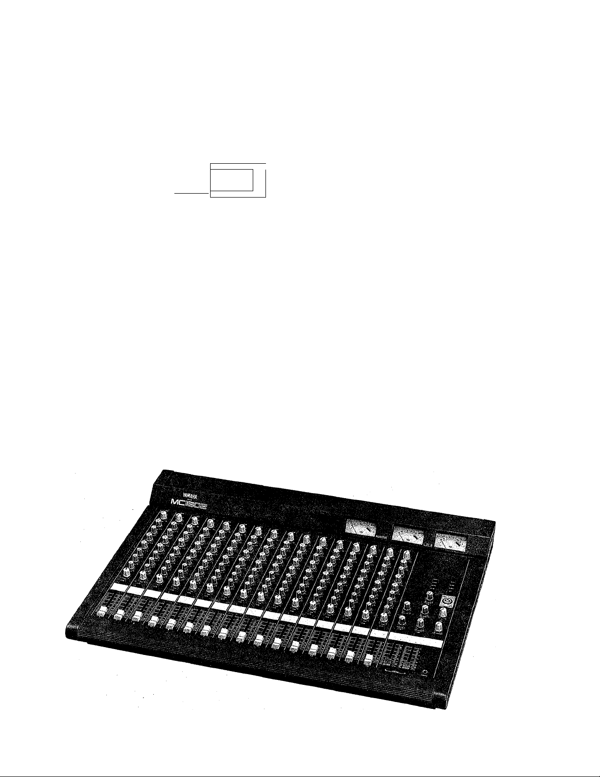
Congratulations!
You are the proud owner of a Yamaha MC-series Mixing Cortsole./Whether you
chose the 8, 12 or 16-channel model, your Yamaha mixing console is a high-quality
product that will give you superior performance in a wide range of applications. In
addition to offering a versatile mixing'system, the MC-series consoles offer electron
ically bahnced inputs and stereo outputs to maintain Optimum signal quality over
long cable runs, a versatile 3-band equalizer with sweepable mid-frequency EQ on
each input channel, three independent AUX submix systems for external effects
routing or additional power amplifier feeds, cue switches for independent monitor
ing of all input channels and busses, and a built-in talkback system for convenient
communication.
Of course, the MC-series mixing consoles also offer the high standard of quality and
great sound that Yamaha is famous for. We urge you to read this operation manual
thoroughly in order to make the most of the mixer’s many features and controls;
CONTENTS
PRECAUTIONS . ...............
FRONT PANEL CONTROLS
inputChannels............... ......... 3
Master Control Section ........................... ...................
REAR PANEL CONNECTORS AND CONTROLS .... 9
APPLICATION EXAMPLE . . .
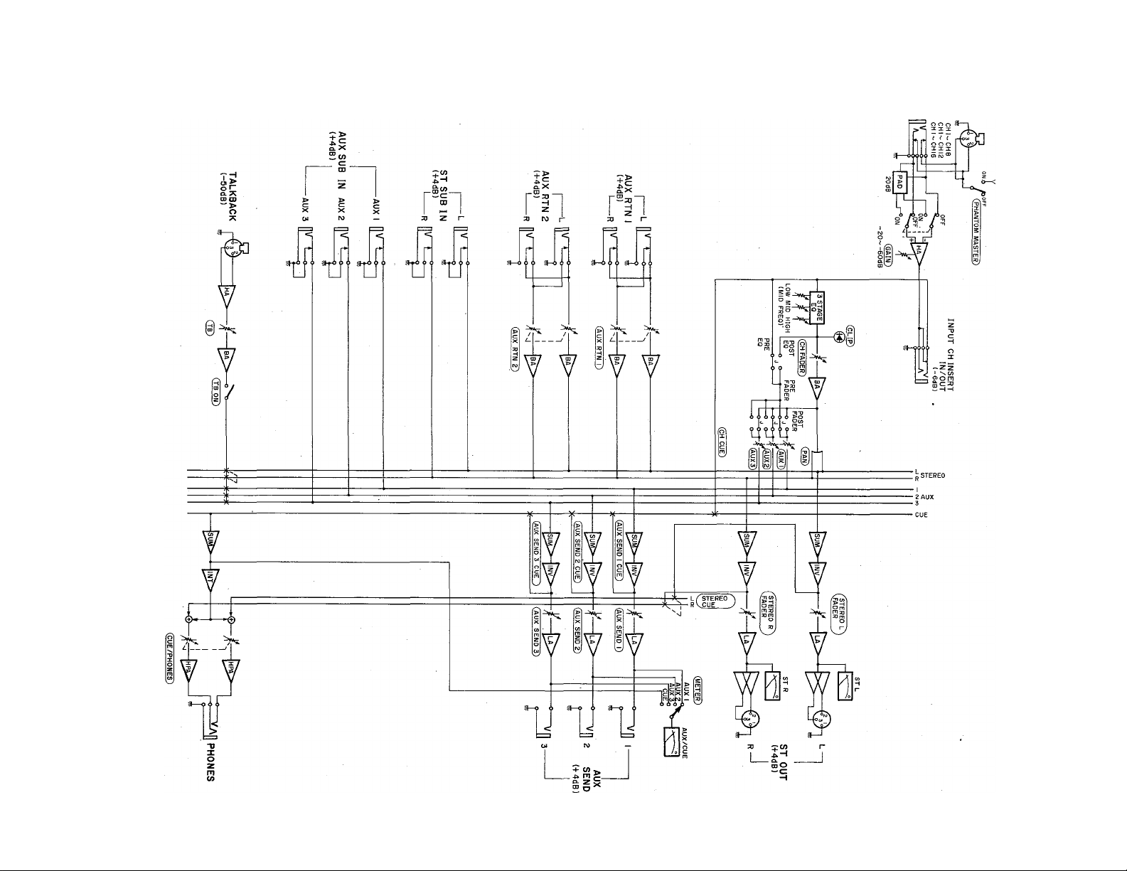
BLOCK DIAGRAM
LEVEL DIAGRAM . . . . .
DIMENSION CHART . . . ................ 13
SPECIFICATIONS ......... . . . ............. 14
SERVICE --------------------------------- ----------- ------------------ 15
.....
..............................
................ .............................
. ......
.................
............
. ..... 12
................... 13
2
3
6
.......
11
Page 3

PRECAUTIONS
I
1. AVOID EXCESSIVE HEAT, HUMIDITY, DUST AND
VIBRATION
Keep the unit away from locations where it is likely to be
exposed to high temperatures or humidity—such as near
radiators, stoves, etc. Also avoid locations which are
subject to excessive dust accumulation or vibration which'
could cause mechanical damage.
2. AVOID PHYSICAL SHOCKS
Strong physical shocks to the unit can cause damage.
Handle it with care.
DO NOT OPEN THE UNIT OR ATTEMPT REPAIRS OR
MODIFICATIONS YOURSELF
This product contains no user-serviceable parts. Refer all
maintenance to qualified Yamaha service personnel. Open
ing the unit and/or tampering with the internal circuitry
will void the warranty.
4. MAKE SURE POWER IS OFF BEFORE MAKING OR
REMOVING CONNECTIONS
Always turn the power OFF prior to connecting or dis
connecting cables. This is important to prevent damage to
the unit itself as well as other connected equipment.
5. HANDLE CABLES CAREFULLY
Always plug and unplug cables-including the AC cord-by
gripping the connector, not the cord.
6. CLEAN WITH A SOFT DRY CLOTH
Never use solvents such as benzine or thinner to clean the
unit. Wipe clean with a soft, dry cloth.
7. ALWAYS USE THE CORRECT POWER SOURCE
Make sure that the power source voltage specified on the
rear panel matches your local AC mains supply.
U.S. & Canadian Models: 120VAC,60Hz
General Model; 110 - 120/220 - 240 V AC, 50/60Hz
Page 4
FRONT PANEL CONTROLS
Input Channels
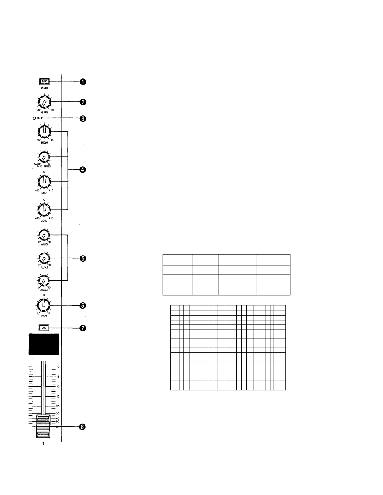
O pad Switch
This switch attenuates the signal applied to the corresponding rear-panel Hl-Z or LO-Z input by
20 dB prior to the head.amplifier and input gain control. The PAD switch effectively increases
the range of input signal levels that can be handled by the mixer, preventing overloading of the
input circuitry when receiving high-level signals.
Q GAIN Control
This control adjusts the input sensitivity of each input channel between —60dB (0.775 mV)
and -20 dB (77.5 mV) when the PAD switch is OFF (between -40 dB and 0 dB when the PAD
switch is ON). Continuously variable gain control allows optimum matching with virtually any
microphone or line source.
0 CLIP LED Indicator
The CLIP indicator LED lights when the post-EQ signal of the corresponding channel's input
reaches a level 3 dB below the clipping level of the channel's circuitry. If the CLIP indicator
lights more than only briefly on high-level transients it is necessary to decrease the input sensi
tivity of the channel using the GAIN control and PAD switch or, if this does not provide
sufficient attenuation, to reduce the output level of the source connected to that channel's
input.
1
O 3-band Equalizer
The equalizer section provided on each input channel comprises shelving LOVV and HIGH con
trols, and a peaking MID control with a MID FREQ control that permits sweeping the midrange
center frequency from 350 Hz to 5 kHz.
Control
HIGH
MID
Maximum
Boost/Cut
+15dB
±15dB
LOW ±15dB
nro
F
/ V
Frequence
10kHz
0.35 ~ 5 kHz Peaking
100Hz
35bn I
11). FRf
0
/ m)
/1
V
FREQUENCY (Hz I
/
,/
/ \
/
N
\
\
V
-N
;v-
o
Shelving
Shelving
■ V
\
Type
Page 5

0
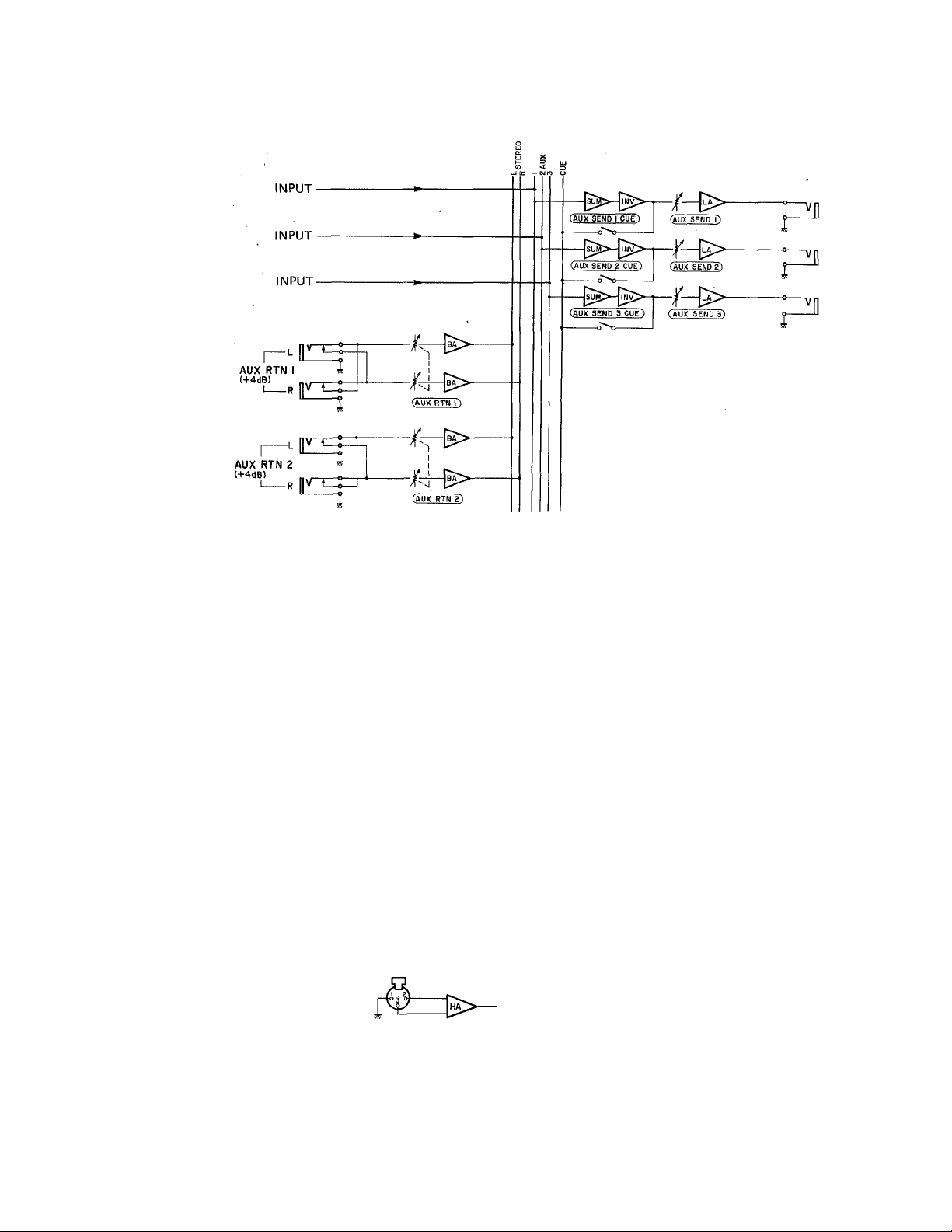
AUX Controls (1,2 &3)
The MC-series mixing consoles have three independent AUX busses which are -fed by the
corresponding AUX controls on the input channels. Each AUX control determines the level of
the signal sent from that channel to the correspondingly numbered AUX mixing buss, which in
turn feeds the correspondingly numbered AUX SEND control and AUX SEND jack on the
console's rear panel. The AUX controls can be used to determine the amount of signal from the
corresponding input channel sent to external effect devices or power amps fed by the AUX
SEND jacks.
* AUX 1 is factory pre-wired for pre-EQ/pre-fader operation, so the AUX 1 signal is not
affected by the setting of the channel EQ controls or fader. An internal jumper allows the
AUX 1 control to be rewired for post-EQ/post-fader operation.
* AUX 2 and AUX 3 are factory pre-wired for post-EQ/post-fader operation, so the AUX 2
and AUX 3 signals are affected by the setting of the channel EQ controls and fader. Internal
jumpers allow the AUX 1 control to be rewired for pre-EQ/pre-fader operation.
* An internal PQST EQ jumper allows the AUX controls to be further re-configured for
post-EQ/pre-fader operation.
* REFER THE ABQVE-MENTIQNED REWIRING JQBS TQ QUALIFIED YAMAHA SER
VICE PERSQNNEL!
I
@ PAN Pots
The PAN pot determines the position in the stereo sound field at which the sound from that
channel is heard. Rotated fully counterclockwise the channel signal will be delivered from the
left stereo output only, and will be heard at the far left of the sound field. If the PAN pot is
turned fully clockwise, the sound from that channel will appear at the far right of the stereo
sound field. If the PAN pot is set at its center position, the channel signal will be sent equally
to both the left and right channels, causing the sound to appear at the center of the sound field.
Intermediate PAN pot settings cause the sound to be heard at the corresponding position.
Ql CUE Switch
When the CUE switch is pressed, the pre-EQ/pre-fader signal from that channel is fed to the
PHQNES output via the CUE/PHONES level control. The channel cue signal will be added to
any other active cue signal. If you want to monitor only the signal from a single channel, make
sure all other CUE switches are turned OFF.
Page 6
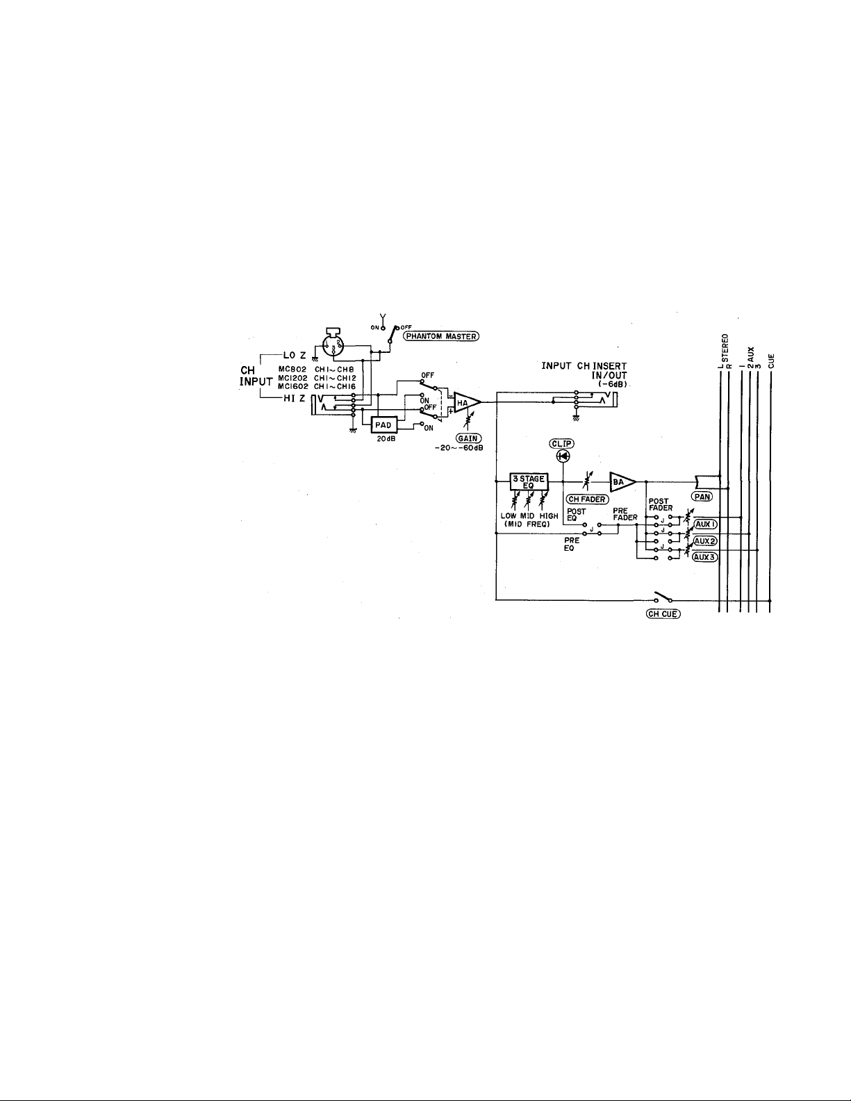
0 Channel Fader
This is the main level control for each input channel. It determines the level of the signal sent
from the corresponding input channel to the master stereo buss. The settings of the input
channel faders determine the "mix" or balance of sound levels between the instruments or
other sources connected to the inputs.
* If a channel is not being used, its fader should be set to the minimum position to prevent
unwanted noise from being added to the main program signal.
Page 7
Master Control Section
[
<0
-A
\ VU
7 ? . ? J 0
AUX/CUE
-A
10 I
20
7 5 3 OPEAK
\ VU
L ST R
10 7 , f . ■ ^ 1 OPEAK
' \ VU ^
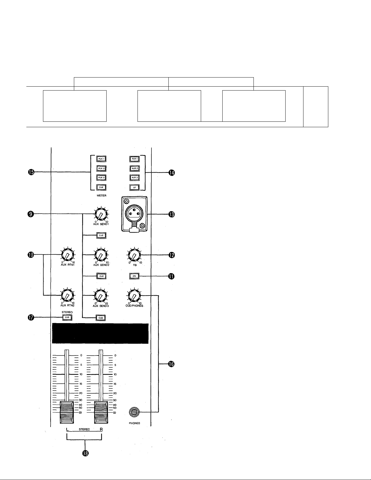
0 AUX SEND (1,2 & 3) Controls & CUE Switches
These adjust the overall output level of the auxiliary
"mixes" set up using the AUX 1, AUX 2 and AUX 3 con
trols on the input channels. AUX SEND 1 sets the overall
level of the AUX 1 mix signal appearing at the AUX
SEND 1 jack, AUX SEND 2 sets the overall level of the
AUX 2 mix signal appearing at the AUX SEND 2 jack,
and AUX SEND 3 sets the overall level of the AUX 3
mix appearing at the AUX SEND 3 jack. These controls
should be used to optimally match the AUX SEND out
put level of the mixing console to the input sensitivity of
the effect unit, signal processing device or amplifier used.
The CUE switches associated with each AUX SEND con
trol can be used to send the corresponding AUX SEND
signal to the PHONES jack via the CUE/PHONES level
control. The AUX cue signal will be added to any other
active cue signal. If you want to monitor only the signal
from a single AUX buss, make sure all other CUE switches
are turned OFF.
D AUX RTN 1 & AUX RTN 2 Controls
These controls adjust the level of the signal received at the
rear-panel AUX RTN jacks and mixed into the main
stereo program. Since stereo AUX returns are provided
(AUX RTN 1 L & R, AUX RTN 2 L & R) the AUX RE
TURN controls simultaneously adjust the level of the
signals appearing at the corresponding L and R return
inputs. The returned L and R channel signals are sent to
the L and R stereo buss lines. If only a single-channel
signal is returned (i.e. a plug is inserted into only the L or
R return jack), the signal will be fed to both the L and R
channels of the stereo buss.
Page 8
0 Talkback ON Switch
Pressing this switch activates the talkback microphone plugged into the talkback mic connector,
allowing voice communication from the console operator to the STEREO, AUX 1, AUX 2 or
AUX 3 busses according to the setting of the talkback assignment switches.
® TB (Talkback) Level Control
Adjusts the level of the talkback signal sent to the selected buss.
2 SEND
(+4dB)
AUX
Talkback Microphone Connector
This female XLR type connector accepts just about any standard 50 ~ 600 ohm microphone
for talkback pickup. A gooseneck-type microphone that can be positioned for the most com
fortable operation is an excellent choice.
({) Talkback Assignment Switches (AUX 1/AUX 2/AUX 3/ST)
These switches allow the talkback signal to be fed to the STEREO, AUX 1, AUX 2 or AUX 3
busses. Any number of switches may be ON at the same time, so you can "talk back" to a
number of the console's busses at once.
TALKBACK
l-50dB)
dD
jVo-
-o'V-
-o'So-
I
->■ ST OUT L
-► ST OUT R
AUX OUT 1
-► AUX OUT 2
AUX OUTS
Page 9
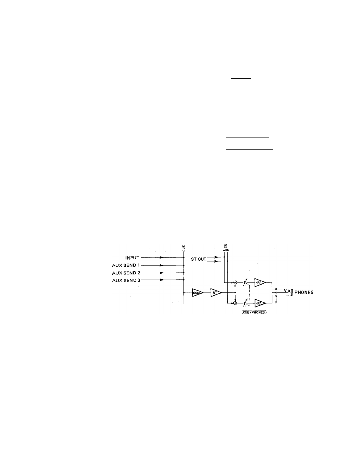
VU Meters and METER Assign Switches (AUX 1/AUX 2/AUX 3/CUE)
The MC-series mixing console feature three VU meters with built-in LED peak indicators for
monitoring signal levels. The rightmost meter pair ( L ST R) continuously monitors signals
on the main stereo program buss. The AUX/CUE meter can be switched to monitor signals on
the AUX 1, AUX 2, AUX 3 or CUE busses by pressing the corresponding METER assign
switch.
I
INPUT
AUXSEND 1 AUXSEND 2AUXSENDS-
® CUE/PHONES Control and PHONES Jack
The CUE/PHONES control adjusts the level of the cue signal sent to the PHONES jack so you
can set the most confortable headphone monitoring level. The stereo phone jack accepts any
standard stereo headphones.
* The STEREO cue signal appears in stereo at the phones jack, while the channel and AUX
cue signals are monaural.
AUX SEND 1
AUX SEND 2
AUX SEND 3
-------
(METER)
AUX 1
AUX 2^
AUX 3-
0 STEREO CUE Switch
Turning this switch ON sends the main stereo program buss signal, in stereo, to the stereo
PHONES jack via the CUE/PHONES control. The STEREO CUE switch can normally be turned
ON to permit headphone monitoring of the main stereo program, but it must be turned OFF
to individually monitor input channel or AUX buss cue signals.
Page 10
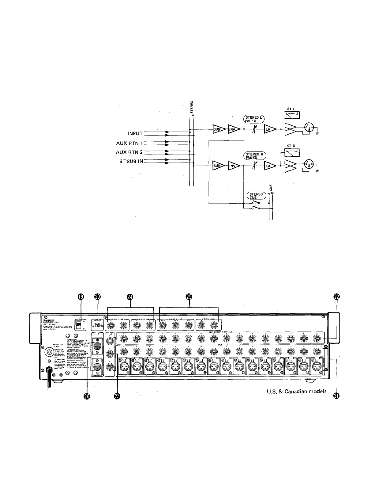
STEREO Master Faders
The STEREO master faders independently adjust the level of the left and right channel main
stereo program buss signajs appearing at the STEREO OUT connectors.
ST OUT
(+4dB)
J
REAR PANEL CONNECTORS AND CONTROLS
Page 11

I
<E) POWER Switch
Flip up to turn power ON, and down to turn power OFF.
The VU meter lamps will light when the power is ON.
® PHANTOM MASTER Switch
Turn this switch ON to apply +48 volts DC to the LO-Z
XLR input connectors when using phantom-powered
condenser microphones.
* NEVER turn the PHANTOM MASTER switch ON
when applying line-sources to the LO-Z inputs.
^ Hi-Z and LO-Z Input Connectors
Each input channel offers a choice of two input connec
tors: a balanced LO-Z (low-impedance) XLR-type connec
tor and a HI-Z (high-impedance) tip-ring-sleeve 1/4"
phone jack. The LO-Z inputs are primarily intended for
use with professional low-impedance microphones or
electronic instruments having low-impedance balanced
outputs. The HI-Z inputs will accept either balanced or
unbalanced signals from high-impedance microphones,
musical instruments or other source equipment.
® INPUT CH INSERT IN/OUT Jacks
These jacks permit inserting compressors, limiters or other
types of external signal processing equipment between the
head amplifier and EQ stage of each input channel. The
jacks are tip-ring-sleeve types, in which the tip is SEND
(the output from the head amplifier), the ring is RETURN
(the input to the EQ stage), and the sleeve is ground.
External equipment may be inserted using "Y" cables
which branch the SEND and RETURN lines from a tip-
ring-sleeve phone plug to two separate mono phone plugs.
INSERT OUT (tip)
cniT
INSERT IN (ring)
® AUX SEND (1,2 & 3) Jacks
These jacks deliver the AUX 1, AUX 2 and ALTX 3 mixes,
respectively, to feed an external effect device or power
amplifier. Nominal output level/impedance is +4 dB/
600 ohms.
AUX RETURN 1 (L & R) & AUX RETURN 2 (L & R) Jacks
The mono or stereo output from effect units fed by the
AUX SEND jacks can be returned to the main stereo
program mix via these jacks. Note that each AUX RE
TURN offers independent return inputs for the left and
right busses, accommodating the return signal from effect
units featuring stereo outputs. Nominal input level/im
pedance is +4 dB/600 ohms.
AUX SUB IN & ST SUB IN Jacks
These five jacks permit "cascading" two MC-series mixing
consoles to increase the number of available input chan
nels. The AUX OUT jacks from the first (slave) console
should be connected to the corresponding AUX SUB IN
jacks of the second (master) console, and the STEREO
outputs from the slave console should be connected to the
corresponding ST SUB IN jacks on the master console.
STEREO OUT L & R Connectors
The MC-series mixing consoles provide balanced XLR con
nector outputs from the main stereo buss. The signal
delivered is a stereo mix of the input channel signals and
the signals returned to the AUX RETURN jacks. The
STEREO OUT signal will normally be used to drive a
power amplifier and speaker system, powered keyboard
speakers or a main house mixing console. Nominal output
level/load impedance is +4 dB/600 ohms.
NOTE: The. MC-series mixing console XLR connectors are
wired according to DIN specifications. Pin 1 is
shield (ground), pin 2 is hot (signal high) and pin 3
is cold (signal low).
10
Page 12
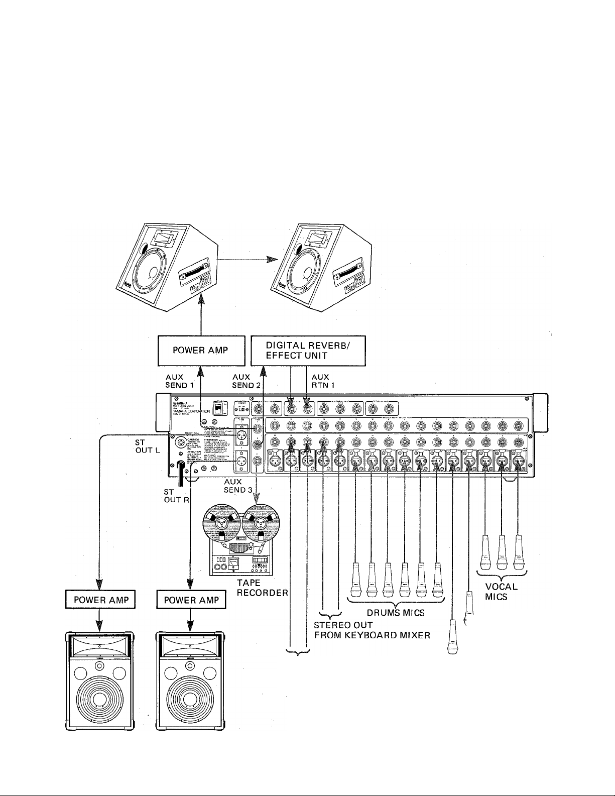
APPLICATION EXAMPLE
In the system shown below the MC1602 is used as the main
console in a sound reinforcement system. Three vocal micro
phones, six drum microphones, a microphone from the guitar
amplifier and another from the bass amplifier are connected
to 11 of the 16 available LO-Z inputs. The line-level stereo
outputs from an on-stage keyboard mixer and the stereo
outputs from an electronic percussion system are fed to four
Hl-Z inputs. A total of 15 input channels are thus used, leav
ing one free — just in case. The AUX 1 mix system feeds
on-stage power amplifiers and monitor speakers for the
STAGE MONITOR
SPEAKERS
performers. The AUX 2 system is used to drive a digital
reverb/effects unit to add ambience and effects where neces
sary. The AUX 3 system feeds a tape recorder to make a
rough mono recording of the performance. T.he STEREO
OUT connectors drive the main house power amplifiers and
speaker systerri.
This is just one possible way of setting up the MC1602 for
a sound reinforcement application. The actual setup you use
will, naturally, be dictated by your own particular system
requirements.
11
HOUSE SPEAKER SYSTEM
STEREO OUT FROM
ELECTRONIC PERCUSSION SYSTEM
=4 ELECTRIC GUITAR
AMP MIC
ELECTRIC BASS
AMP MIC
Page 13
глл
о
n
>
о
то
>
Page 14
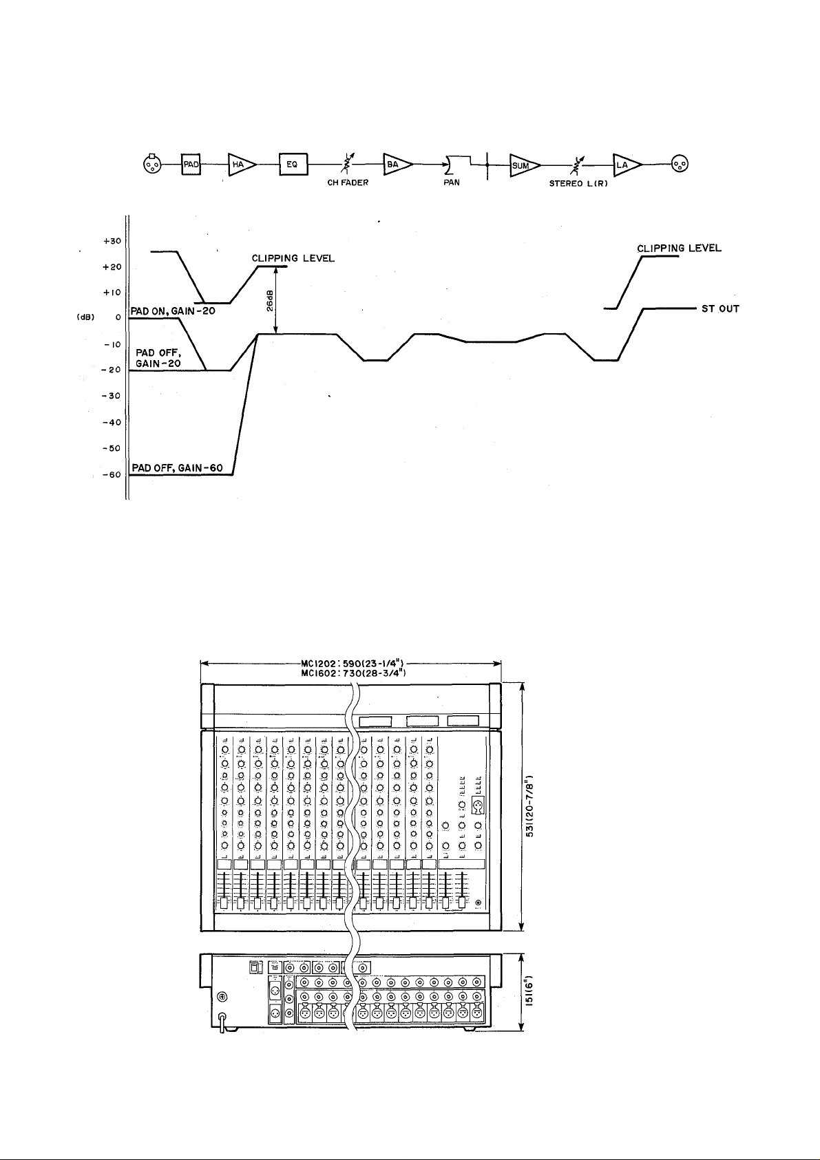
LEVEL DIAGRAM
FADER
DIMENSION CHART
13
Unit: mm (Inch)
Page 15

SPECIFICATIONS
I
Total Harmonic
Distortion
Frequency Response +1,-3dB, 20Hz - 20kHz (3)+4dB into
Hum and Noise* (20Hz —128dB
— 20kHz, Rs=150 ohms, —90dB
Input Gain max.. Input
Pad @ OdB, Input —73dB
Sensitivity —60dB)
Maximum Voitage Gain
Input Channel Gain Control
—20~—60dB variation in gain, stop to stop.
Input Channel Pad Switch
0/20dB of attenuation.
Input Channel Equalization
15dB maximum boost or cut in each of three bands.
HIGH: 10kHz (shelving)
MID: 350Hz - 5kHz (peaking)
LOW: 100Hz (shelving)
Crosstalk
VU Meters (0 VU = +4dB Output)
3 iliuminated meters.
STEREO L, STEREO R, AUX 1/AUX 2/AUX 3/CUE (switchable)
Clip Indicators
RED LED built into each input channel. Lights when post-EQ
channel signal is 3dB below clipping level.
Less than 0.1%, 20Hz - 20kHz @ +14dB
into 600 ohms.
600 ohms
equivalent input noise,
residual output noise (balanced
outputs).
at STEREO OUT with master
fader at nominal level and all
-64dB
-70dB
-64dB
84dB
84dB
94dB
20dB
lOdB
lOdB SUB IN to STEREO OUT
-60dB at 1 kHz, adjacent input channels.
-60dB at 1 kHz, input to output.
channel faders at minimum level,
at STEREO OUT with master
fader and one channel fader at
nominal level
at AUX SEND with AUX SEND
level control at nominal level
and all channel AUX controls at
minimum level.
at AUX SEND with AUX SEND
and one AUX control at nominal
level.
CH IN to STEREO OUT
CH IN to AUX SEND 1
CH IN to AUX SEND 2,3
AUX RETURN 1,2 to STEREO OUT
SUB IN to AUX SEND 1 - 3
Phantom Power
+48 VDC applied to electronically balanced inputs via 6.8 k-ohm
limiting resistors. Master ON/OFF switch.
Power Requirements
U.S. & Canadian models: 120V AC, 60Hz
General model: 110 - 120/220 -240V AC, 50/60Hz
Power Consumption
Dimensions (W x H x D)
MCI 602:
MCI 202:
MC802:
Weight MC1602: 18 kg. (39.7 lbs.)
• Measured with a —6dB/octave LPF (s> 12.7kHz.
• OdB = 0.775Vr.m.s.
• Specifications subject to change without notice.
730 mm
(28-3/4"X6" X 20-7/8")
590 mm X 151 mm X 531 mm
(23-1/4" X
450 mm X 151mm X 531 mm
(17-3/4" X 6" X 20-7/8")
MCI 602:
MCI 202:
MC802:
X
151 mm X 531 mm
X 20-7/8")
6"
MCI202: 15 kg. (33.1 lbs.)
MC802: 12 kg. (26.4 lbs.)
60 watts
50 watts
40 watts
14
Page 16

INPUT CHARACTERISTICS
INPUT
PAD
CH INPUT
INPUT CH INSERT IN
ST SUB IN.AUX SUB IN
AUX RTN
TALKBACK IN
OFF(OdB)
ON{20dB)
GAIN
-60dB
-20dB
INPUT
IMPEDANCE
LO-Z 4k ohms
Hl-Z 10k ohms
10k ohms
10k ohms
10k ohms
4k ohms
■ OUTPUT CHARACTERISTICS
OUTPUT
STOUT
AUX SEND 1 ~3
INPUT CH INSERT OUT
PHONES
OUTPUT
IMPEDANCE
150 ohms
150 ohms
600 ohms 10k ohms Lines
100 ohms
INPUT LEVELS
SOURCE
IMPEDANCE
50 ~600 ohms
Microphones
or
600 ohms Lines
600 ohms Lines -26dB (38.8mV) -6dB (388mV)
600 ohms Lines
600 ohms Lines
50 ~ 600 ohms
Microphones
LOAD IMPEDANCE
600 ohms Lines +4dB (1.23V)
600 ohms Lines
8 ohms Phones ImW
40 ohms Phones 3mW
SENSITIVITY**
-80dB (O.OSmV) -60dB (0.8mV)
-40dB (7.75mV)
-20dB (77.5mV)
-6dB (388mV)
-16dB (123mV)
-70dB (0.25mV)
RATED LEVEL
-H4dB (1.23V)
-6dB (388mV)
RATED LEVEL
-20dB (77.5mV)
OdB (775mV) +26dB (15.5V)
+4dB (1.23V)
+4dB (1.23V)
-50dB (2.45mV)
OUTPUT LEVELS
MAXIMUM NON
CLIPPING LEVEL
+24dB (12.3V)
+20dB (7.75V)
-l-20dB (7.75V)
MAXIMUM
NON CLIPPING
LEVEL
-34dB (15.5mV)
+6dB (1.55V)
+20dB (7.75V)
+20dB (7.75V)
-24dB (48.9mV)
20mW
130mW
CONNECTOR
XLR-3-31 type
Phone Jack (TRS)
Phone Jack (TRS)
(Unbalanced)
(Unbalanced)
-
(Unbalanced)
XLR-3-31 type
(Unbalanced)
CONNECTOR TYPE
XLR-3-32type
(Balanced)
Phone Jack
(Unbalanced)
Phone Jack (TRS)
(Unbalanced)
Stereo Phone Jack
(Unbalanced)
Type
(Balanced)
and
(Balanced)
Phone Jack
Phone Jack
** Input level required to produce rated +4dB output level.
• OdB = 0.775Vr.m,s.
This product is supported by Yamaha’s worldwide network of
factory trained and qualified dealer service personnel. In the event
of a problem, contact your nearest Yamaha dealer.
SERVICE
15
Page 17

Tables de mixage de la série MC
ÿ
□Jg
il
d
Manuel d’utilisation
16
Page 18

Félicitations!
Vous êtes l’heureux propriétaire d’une table de mixage Yamaha de la série MC. Que
vous ayez choisi le modèle à 8, 12 ou 16 canaux, votre table de mixage Yamaha est
un produit de haute qualité qui vàus donnera des résultats supérieurs dans une large
gamme d’applications.
Outre leur système de mixage puissant, les tables de mixage de la série MC présen
tent également des entrées et des sorties stéréo équilibrées électroniquement
pour conserver un signal de qualité optimale dans le cas de longues transmissions
par câble, un correcteur de timbre à trois bandes avec bande intermédiaire mou
vante sur chaque canal d’entrée, trois systèmes de mixage secondaires A UX indé
pendants pour alimenter des appareils générateurs d’effets externes ou des systèmes
d’amplification supplémentaires, des touches CUE pour contrôler indépendamment
tous les canaux d’entrée et bus et un système "Talkback” intégré pour des com
munications aisées.
Avec les tables de mixage amplifiées de la série MC, vous retrouverez le son et la
qualité qui ont fait la réputation de Yamaha.
Veuillez lire attentivement ce manuel d’utilisation afin de pouvoir tirer le meilleur
parti des fonctions et commandes de votre nouvelle table de mixage.
17
TABLE DES MATIERES
PRECAUTIONS ............................................................................. 18
COMMANDES DU PANNEAU AVANT
Canaux d'entrée ................................................................... ig
Section des commandes martres
CONNECTEURS ET COMMANDES DU
PANNEAU ARRIERE......................................................................25
EXEMPLE D'UTILISATION .....................................................• • - 27
SCHEMA DE PRINCIPE................................................................. 28
SCHEMA DE NIVEAU
TABLEAU DES DIMENSIONS....................................................... 29
FICHE TECHNIQUE
SERVICE APRES-VENTE.............................................................. 31
....................................................................
........................................................................
............................................
........................................
22
29
19
39
Page 19

PRECAUTIONS
1. EVITEZ LES CHALEURS EXCESSIVES, L'HUMIDITE,
LA POUSSIERE ET LES VIBRATIONS
Evitez d'installer cet appareil dans des endroits où il pour
rait être exposé à une température ou une humidité exces
sives (à proximité d'un appareil de chauffage, par exem
ple). Evitez également les endroits poussiéreux ou soumis
à des vibrations, car cela pourrait entramer des problèmes
mécaniques.
2. EVITEZ LES CHOCS
Les chocs risquent de provoquer des dommages internes.
Manipulez cet appareil avec précaution.
3. N'OUVREZ PAS L'APPAREIL ET N’ESSAYEZ
PAS DE LE MODIFIER OU DE LE REPARER
PAR VOUS-MEME
Cet appareil ne contient aucun élément que l'utilisateur
est en mesure de modifier ou de réparer par lui-même.
Confiez tout travail d'entretien ou de révision au person
nel compétent du service après-vente Yamaha. Le fait
d'ouvrir l'appareil et/ou de bricoler les circuits internes
entramera l'annulation automatique de la garantie du
produit.
4. METTEZ L'APPAREIL HORS TENSION AVANT DE
TOUCHER AUX CONNEXIONS
Mettez toujours l'appareil hors tension avant de connecter
ou de déconnecter des câbles. Ceci est important afin
d'éviter d'endommager non seulement l'appareil lui-même,
mais également les autres appareils connectés.
5. MANIPULEZ LES CABLES AVEC PRECAUTION
Lorsque vous branchez ou débranchez des câbles, tenez-les
toujours par la fiche. Ne tirez pas sur le cordon.
6. NETTOYEZ AVEC UN CHIFFON DOUX ET SEC
Nettoyez le coffret uniquement avec un chiffon doux et
sec. N'utilisez jamais de solvants ou de diluants pour pein
ture.
7. UTILISEZ TOUJOURS UN COURANT D'ALIMENTA
TION DE TENSION CORRECTE
Assurez-vous que la tension du secteur correspond à celle
indiquée sur le panneau arrière.
Modèle pour les Etats-Unis et le Canada: 120V
secteur, (105-130V), 60 Hz
Modèle universel: 110—120/220—240V secteur
(± 10%), 50/60 Hz
18
Page 20

COMMANDES DU PANNEAU AVANT
' Canaux d'entrée -
O Touche PAD
Cette touche atténue de 20 dB le signal fourni à l'entrée HI-Z ou LO-Z correspondante du pan
neau arrière, avant le pré-a'mplificateur et la commande de gain d'entrée. La touche PAD élargit
effectivement la plage des niveaux de signal d'entrée qui peuvent être, traités par la table de
mixage en empêchant la saturation des circuits d'entrée lors de la réception de signaux à haut
niveau.
0 Commande de GAIN
Cette commande règle la sensibilité d'entrée de chaque canal d'entrée entre —60 dB (0,775 mV)
et —20 dB (77,5 mV), lorsque la touche PAD est en position OFF (entre -40 dB et 0 dB, lors
que la touche PAD est en position ON). Ce type de commande de gain à réglage variable et
continu permet une mise à niveau optimale avec pratiquement n'importe quelle source, ligne
ou micro.
0 Indicateur à DEL CLIP (écrêtage)
L'indicateur à DEL CLIP s'allume lorsque le signal après correction EQ du canal d'entrée
correspondant atteint un niveau situé à 3 dB en dessous du niveau d'écrêtage des circuits du
canal. Si l'indicateur CLIP s'allume autrement que brièvement dans les passages à haut niveau,
il est nécessaire de diminuer la sensibilité d'entrée du canal au moyen de la commande de GAIN
ou de la touche PAD correspondante ou, si cela ne suffit pas, de réduire le niveau de sortie de
la source connectée à l'entrée de ce canal.
O Correcteur à trois bandes
La correction de timbre (EQ) de chaque canal d'entrée est assurée par des commandes de cou
pure (shelving) LOW et HIGH et une commande d'écrêtage (peaking) MID, à laquelle est as
sociée une commande MID FREQ qui permet de déplacer la fréquence centralë de la bande
intermédiaire entre 350 et 5 kHz.
Commande
HIGH
MIDDLE ±15dB
LOW
Acc,/Att,
max.
±15dB
±15dB
FREQUENCY(Hz)
Fréquence Type
8kHz Coupure
0,35-5kHz Ecrêtage
100Hz Coupure
19
Page 21

O Commande AUX (1,2, & 3)
Les tables de mixage de la série MC possèdent trois bus AUX indépendants qui sont alimentés
par les commandes AUX correspondantes sur les canaux d'entrée. Chaque commande AUX
détermine le niveau du signal envoyé par le canal au bus de mixage AUX du numéro corres
pondant qui, à son tour, alimente la commande AUX SEND et la prise AUX SEND du panneau
arrière ayant le numéro.correspondant. Les commandes AUX peuvent être utilisées pour déter
miner la quantité de signal du canal correspondant envoyée à des appareils générateurs d'effets
externes ou des amplificateurs de puissance alimentés par les prises AUX SEND.
* AUX 1 a été pré-câblé à l'usine en position avant lè correcteur EQ et avant l'atténuateur, de
sorte que le signal AUX 1 n'est pas affecté par les réglages des commandes de correction oü
de l'atténuateur du canal. Des pontages internes permettent de recâbler la commande AUX 1
en position après le correcteur EQ et après l'atténuateur.
* AUX 2 et AUX 3 ont été pré-câblés à l'usine en position après le correcteur EQ et après
l'atténuateur, de sorte que les signaux AUX 2 et AUX 3 sont affectés par les réglages des
commandes de correction et de l'atténuateur du canal. Des pontages internes permettent de
recâbler les commandes AUX 2 et AUX 3 avant le correcteur EQ et avant l'atténuateur du
canal.
* Des pontages internes PQST EQ permettent, en outre, de recâbler les commandes AUX en
position après correcteur le EQ et avant l'atténuateur.
* CONFIEZ CES OPERATIONS A VOTRE CONCESSIONNAIRE YAMAHA OU A UN
CENTRE DE SERVICE QUALIFIE!
O Commandes PAN
La commande PAN détermine la position du son du canal correspondant dans le panorama
stéréo. Lorsqu'elle est tournée à fond dans le sens contraire des aiguilles d'une montre, le signal
du canal est envoyé à la sortie stéréo gauche uniquement et le son paraft provenir de l'extrême
gauche du panorama stéréo. Lorsqu'elle est tournée à fond dans le sens des aiguilles d'une
montre, le signal du canal est envoyé à la sortie stéréo droite uniquement et le son paraît
provenir de l'extrême droite du panorama stéréo. Lorsqu'elle est réglée sur la position centrale,
le signal du canal est réparti de manière équilibrée entre les voies stéréo gauche et droite et le
son paraft provenir du milieu du panorama stéréo. Lorsqu'elle est réglée sur une position inter
médiaire, le son prapft provenir de la position correspondante.
O Commande CUE
Lorsque la commande CUE est pressée, le signal avant correcteur EQ et avant atténuateur du
canal correspondant est envoyé à la sortie PHONES via la commande de niveau CUE/PHONES.
Le signal CUE (pilote) du canal sera ajouter à tout autre signal CUE actif. Pour entendre le
signal d'un seul canal, assurez-vous que toutes les autres commandes CUE sont en position OFF.
20
Page 22

O Atténuateur de canal
Cet atténuateur constitue la principale commande de niveau pour chacun des canaux d'entrée.
Il détermine le niveau du signal envoyé, à partir du canal d'entrée correspondant, au bus stéréo
maftre. La position des atténuateurs des canaux d'entrée détermine le "mixage" ou équilibre de
niveau entre les sons des divers instruments et autres sources connectées aux entrées.
* Si un canal n'est pas utilisé, son atténuateur doit être réglé sur la position minimum pour
éviter que des bruits indésirabies ne soient mêlés au signal du programme principal.
21
Page 23

-Section des commandes martres-
I
©Commandes AUX SEND (1,2, & 3) & touches CUE
Ces commandes ajustent le niveau de sortie global des
"mixages" secondaires effectués au moyen des com
mandes AUX 1, AUX 2 et AUX 3 des canaux d'entrée.
AUX SEND 1 règle le niveau global du signal du mixage
AUX 1 fourni à la prise AUX SEND 1, AUX SEND 2
règle le niveau global du signal du mixage AUX 2 fourni
à la prise AUX SEND 2 et AUX SEND 3 règle le niveau
global du signal du mixage AUX 3 fourni à la prise AUX
SEND 3. Ces commandes servent à adapter de manière
optimale le niveau de sortie AUX SEND de la table de
mixage à la sensibilité d'entrée de l'appareil générateur
d'effets, de traitement de signal ou d'amplification con
necté. La touche CUE associée à chacune des commandes
AUX SEND sert à envoyer le signal AUX SEND corres
pondant à la prise PHONES via la commande de niveau
CUE/PHONES. Le signal pilote AUX s'ajoutera à tout
autre signal pilote actif. Si vous ne voulez entendre que
le signal d'un seul bus AUX, assurez-vous que toutes
les autres touches CUE sont sur la position OFF.
© Commandes AUX RTN 1 & AUX RTN 2
Ces commandes règlent le niveau du signal reçu sur les
prises AUX RTN correspondantes du panneau arrière et
mixé dans le programme stéréo principal. Etant donné
que des retours AUX stéréo sont disponibles (AUX
RTN 1 L & R, AUX RTN 2 L & R), les commandes AUX
RTN contrôlent simultanément le niveau des signaux
fournis aux entrées RETURN L et R correspondantes. Les
signaux de retour des canaux L et R sont envoyés aux
lignes L et R du bus stéréo. Si le signal de retour'n'arrive
que sur un seul canal (c'est-à-dire si une fiche seulement
est insérée, soit dans la prise de retour L, soit dans la prise
de retour R), ce signal sera fourni aux deux canaux L et
R du bus stéréo.
22
Page 24

2 SEND
<DTouche (TALKBACK) ON
Appuyez sur cette touche pour activer le micro branché au connecteur prévu à cet effet et
transmettre la voix du mixeur aux bus STEREO, AUX 1, AUX 2 ou AUX 3, en fonction du
réglage des touches d'assignation de "talkback".
(^Commande de niveau TB (TALKBACK)
Règle le niveau du signai "talkback" envoyé au bus sélectionné.
AUX
(+4 dB )
23
(^Connecteur de micro pour "talkback"
Ce connecteur de type XLR femelle accepte n'importe quel type de micro dans la plage 50 —
600^. Nous recommandons cependant un micro de type "col de cygne", qui peut être placé
dans une position optimale sans gêner la manipulation des commandes.
(E) Touches d'assignation de "talkback"
Ces touches permettent d'envoyer le signal de "talkback" aux bus STEREO, AUX 1, AUX 2 ou
AUX 3. Plusieurs de ces touches peuvent être sur la position ON simultanément, de sorte que
le signal "talkback" peut être envoyé simultanément à différentes bus de la table de mixage.
ST OUT L
ST OUT R
TALKBACK
(-50dB)
► AUX OUT 1
AUX OUT 2
AUX OUT 3
Page 25

®VU-mètres et touches d'assignation METER (AUX 1/AUX 2/AUX 3/CUE)
Les tables de mixage de la série MC sont pourvues de trois VU-mètres avec indicateurs de crête
à DEL incorporés pour contrôler le niveau des signaux. La paire d'indicateurs située à l'extrême
droite (L ST R) contrôle toujours le signal du bus du programme stéréo principal tandis que
l'indicateur AUX/CUE peut être affecté au contrôle du signal des bus AUX 1, AUX 2, AUX 3
ou CUE en appuyant sur la touche d'assignation METER correspondante.
I
INPUT
AUX SEND 1 AUX SEND 2AUXSEND3-
AUX SEND 1
AUX SEND 2
AUX SEND 3
------------
------------->
(meteP)
>
____
AUX 2^
AUOo
SI
(^Commande CUE/PHONES et prise PHONES
La commande CUE/PHONES règle le niveau du signal pilote envyoé à la prise PHONES et
permet donc de régler le niveau d'écoute du casque. La prise PHONES accepte n'importe quel
casque d'écoute stéréo.
* Ce signal pilote est STEREO tandis que les signaux pilotes des canaux et des bus AUX est
MONO.
®Touche STEREO CUE
Lorsque cette touche est en position ON, le signal du bus du programme stéréo principal est
envoyé en stéréo à la prise PHONES via la commande CUE/PHONES. La touche STEREO CUE
peut être placée sur la position ON pour l'écoute au casque du programme stéréo principal, mais
doit être mise sur la position OFF pour l'écoute individuelle des signaux pilotes des canaux
d'entrée ou des bus AUX.
24
Page 26

® Atténuateurs maîtres STEREO
Les atténuateurs maîtres STEREO règlent indépendamment les signaux des voies gauche et
droite du bus du programme stéréo principal, qui sont fournis aux connecteurs STEREO OUT.
ST OUT
(+4dB)
J
CONNECTEURS ET COAAMANDES DU PANNEAU ARRIERE
25
Page 27

I
(Dinterrupteur général (POWER)
Levez pour mettre sous tension et abaissez pour mettre
hors tension. Les lampes des VU-mètres s'allument lorsque
l'appareil est mis sous tension.
^Commutateur PHANTOM MASTER
Mettez ce commutateur sur la position ON pour appliquer
un courant continu de +48V aux connecteurs d'entrée
XLR LO-Z, lorsque vous utilisez des micros à condensa
teur à alimentation en fantôme.
* Ne mettez JAMAIS le commutateur PHANTOM
MASTER sur la position ON lorsque des sources de
niveau ligne sont connectées aux entrées LO-Z.
® Connecteurs d'entrée Hl-Z et LO-Z
Chaque canal d'entrée offre le choix entre deux connec
teurs d'entrée: un connecteur symétrique de type XLR à
basse impédance ( LO-Z) et une prise "jack" pointe-anneaumanchon d' 1/4 de pouce à haute impédance (Hl-Z). Les
entrées LO-Z sont destinées à recevoir essentiellement des
microphones professionnels à basse impédance ou des
instruments électroniques ayant des sorties symétriques
à basse impédance. Les entrées Hl-Z acceptent aussi bien
les signaux symétriques que les signaux asymétriques de
microphones, d'instruments de musique ou d'autres
appareils sources à haute impédance.
® Prises INPUT CH INSERT IN/OUT
Ces prises permettent d'insérer des compresseurs, limiteurs
et autres appareils générateurs d'effets entre les étages de
pré-amplification et de correction EQ de chaque canal
d'entrée. Ces prises de type pointe-anneau-manchon sont
câblées comme suit: pointe = SEND (la sortie du pré
amplificateur), anneau = RETURN (l'entrée du correcteur
EQ), manchon = masse. Les appareils externes peuvent
être branchés en utilisant des câbles en "Y" qui connec
tent les lignes SEND et RETURN d'une seule prise "jack"
de type pointe-anneau-manchon à deux prises "jack"
mono sérarées.
INSERT OUT (pointe)
®Prises AUXSEND (1,2,&3)
Ces prises fournissent les mixages AUX 1, AUX 2 et AUX
3, respectivement, à un appareil générateur d'effets ou à
un amplificateur de puissance externe. Le niveau de sortie
nominal est de +4 dB/600i2.
® Prises AUX RTN 1 (L & R) & AUX RTN 2 (L 8e R)
Les sorties mono ou stéréo d'appareils générateurs d'effets
alimentés par les prises AUX SEND peuvent être ramenées
dans le mixage du programme stéréo principal via ces
prises. Remarquez que chaque prise AUX RETURN offre
des entrées retour indépendantes pour les bus gauche et
droit pour accommoder le signal de retour d'appareils qui
possèdent des sorties stéréo. Le niveau d'entrée nominal/
impédance est de —20 dB/600S2.
® Prises AUX SUB IN 8t ST SUB IN
Ces cinq prises permettent la connexion "en cascade" de
deux tables de mixage pour augmenter, le nombre de
canaux d'entrée disponibles. Les prises AUX SEND de la
première table de mixage (asservie) doivent être connec
tées aux prises AUX SUB IN de la seconde table de mix
age (maPtre) et les sorties STEREO OUT de la table de
mixage asservie doivent être connectées aux prises ST SUB
IN correspondantes de la table de mixage maître.
^Connecteurs STEREO OUT L 8t R
Les tables de mixage de la série MC possèdent des sorties à
connecteur XLR symétrique pour le bus stéréo principal.
Le signal fourni est un mixage stéréo des signaux des
canaux d'entrée et des signaux de retour ramenés par les
prises AUX RETURN. Le signal STEREO OUT attaque
normalement un système amplificateur de puissance/
haut-parleurs, des haut-parleurs de clavier ou une table de
mixage principale. Le niveau de sortie nominal/impédance
de charge est de +A dB/600S2.
REMARQUE: Les connecteurs XLR des tables de mixage de
la série MC sont câblés selon la norme DIN:
broche 1 = blindage (masse), borche 2 = chaud
(signal haut) et broche 3 = froid (signal bas).
OTE
INSERT IN (anneau)
26
Page 28

EXEMPLE D'UTILISATION
Dans le système illustré ci-dessous, l'l\/IC1602 est utilisée
comme table de mixage principale dans un système de ren
forcement de son. Trois micros pour les voix, six micros pour
les percussions, un micro pour l'amplificateur de guitare et
un autre pour l'amplificateur de basse sont connectés à 11
des 16 entrées LO-Z disponibles. Les sorties stéréo de niveau
ligne d'un mixeur de clavier sur scène et les sorties stéréo
d'un système de percussions électronique sont envoyées à
quatre entrées Hl-Z. En tout, 15 canaux d'entrée sont donc
utilisés. Le dernier est gardé en réserve. Le système de mixage
AUX 1 alimente des amplificateurs de puissance sur scène et
HAUT-PARLEURS DE
CONTROLE SUR SCENE
les haut-parleurs de contrôle des exécutants. Le système
AUX 2 attaque une unité de réverbération/effets numérique
pour ajouter de l'ambiance et des effets lorsque cela est
nécessaire. Le système AUX 3 alimente un enregistreur à
bande qui enregistre l'exécution en mono. Les*connecteurs
STEREO OUT attaquent les amplificateurs de puissance et
haut-parleurs principaux.
Cet exemple ne constitue qu'une des applications possibles
de l'MC1602 dans un système de renforcement de son. Le
système que vous monterez dépendra bien sûr de vos exi
gences et du matériel dont vous disposez.
27
'
1^1
SYSTEME DE HAUT-PARLEURS
PRINCIPAL
MICROS DES
PERCUSSIONS
SORTIES STEREO
DE MIXEUR DE CLAVIER
SORITES STEREO DU SYSTEME
DE PERCUSSIONS ELECTRONIQUE
MICROS DES
VOIX
MICRO DE L'AMPLI. DE
GUITARE ELECTRIQUE
MICRO DE L'AMPLI. DE
BASSE
Page 29

SCHEMA DE PRINCIPE
I
28
Page 30

SCHEMA DE NIVEAU
FADER
TABLEAU DES DIMENSIONS
MC802 : 450(17-3/4")
29
Unité: mm (pouce)
Page 31

FICHE TECHNIQUE
I
Distorsion harmonique
totale
Réponse en fréquence
Ronflement et bruit*
(20 Hz - 20 kHz,
Rs = 150 fl. Gain max.,
PAD @ OdB, sensibilité
d'entrée —60 dB)
Gain en tension maximum CH IN à STEREO OUT .
Commande de gain des
canaux d'entrée
Touche PAD des canaux
d'entrée
Correction des canaux
d'entrée
Diaphonie
VU-mètres (0 V = sortie
de +4 dB)
Indicateurs CLIP DEL rouge incorporée associée à chacun
Moins de 0,1%, 20Hz - 20 kHz
@ +14 dB sur 600 n
+1,-3 dB,20 Hz-20 kHz
@ +4 dB sur 600 iî
Bruit,à l'entrée équivalent à .... —128dB
Bruit résiduel ô la sortie
(sorties symétriques)
Bruit résiduel aux sorties STEREO OUT
avec l'atténuateur maftre au niveau
maximum et les atténuateurs de tous les
canaux au niveau minimum .... — 73dB
Bruit résiduel aux sorties STEREO OUT
avec l'atténuateur maftre et l'atténua
teur d'un canal au niveau nominal
Bruit résiduel aux sorties AUX SENO
avec la commande de niveau AUX SEND
au niveau nominal et les commandes
AUX de tous les canaux au niveau
minimum
Bruit résiduel aux sorties AUX SEND
avec la commande AUX SEND et
une des commandes AUX au niveau
nominal
CH INàAUXSENDI .................... 84dB
CH INàAUXSEND2,3
AUX RETURN 1,2 à
STEREO OUT
SUB IN à AUX SEND 1-3
SUB IN à STEREO OUT.
Variation de gain de —20
butée à butée.
0/20 dB d'atténuation
Accentuation ou atténuation max. de
15 dB dans chacune des trois bandes
HIGH: 10 kHz (coupure)
MID: 350 Hz - 5 kHz (écrêtage)
LOW: 100 Hz (coupure)
—60 dB à 1 kHz, entre canaux d'entrée
adjacents
—60 dB à 1 kHz, entrée à sortie
3 indicateurs éclairés
STEREO L, STEREO R, AUX 1/AUX 2
/AUX 3/CUE (commutable)
des canaux d’entrée. S'allume lorsque
le signal du canal après correction
atteint un niveau situé à 3 dB sous le
niveau d'écrêtage.
..................................
..................................
............................
............
...........
...........
...............
..........
.........
---
— BOdB
- 64dB
— 70dB
— 64dB
84dB
94dB
20dB
lOdB
lOdB
60 dB, de
Courant fantôme Un courant de +48 V est appliqué aux
Alimentation Modèle pour les Etats-Unis et le
Consommation MCI 602: 60 W
Dimensions (L x H x P) MCI 602: 730 mm x 151 mm x 531 mm
Poids
* Mesuré avec un filtre passe-bas de —6 dB/octave @ 12,7 kHz.
* 0dB = 0,775 Vr.m.s.
* Spécifications susceptibies d'être modifiées sans préavis.
entrées électroniquement équilibrées via
des résistances de limitation de 6,8 kf2
Commutateur ON/OFF maître
Canada: 120V secteur, 60 Hz
Modèle général : 110-120/220 - 240V,
50/60 Hz
MCI 202 : 50 W
MC802: 40 W
MCI 202: 590 mm x 151 mm x 531 mm
MC802: 450 mm x 151 mm x 531 mm
MCI 602: 18 kg (39,7 Ibs)
MC1202: 15kg(33,1 Ibs)
MC802: 12 kg (26,4 Ibs)
(28-3/4" X 6" x 20-7/8")
(23-1/4" X 6" X 20-7/8")
(17-3/4" X 6" X 20-7/8")
30
Page 32

■ CARACTERISTIQUES D'ENTREE
ENTREE
PAD GAIN
OFF
ENTREE
CANAL
INPUT CH INSERT IN
ST SUB IN,
AUX RTN
TALKBACK IN
gaiisiiiiiilijip
(UilBi
ON
l?OdBl
AUX SUBIN
-60dB
-20dB
IMPEDANCE
D'ENTREE DE SOURCE
LO-Z 4k£2
Hl-Z10kn
lOkn
lOkiï
lOkn
4ki2
CARACTERISTIQUES DE SORTIE
SORTIE
ST DUT 150S2
AUX SEND 1 -^3
INPUT CH INSERT OUT 60022
PHONES 100S2
IMPEDANCE
DE SORTIE
150n Lignes 600£2
NIVEAUX D'ENTREE
IMPEDANCE
Micros
50 ~600S2
ou lignes
600JÎ2
Lignes 600Î2
Lignes 600£2 -6dB (388mV)
Lignes 600f2
Micros
50 ~600n
IMPEDANCE
DE CHARGE
Lignes 600n
Lignes 10ki2
Casque 8£2 ImW 20m)/V
Casque 40 £2
SENSIBILITE**
-BOdB (0,08mV) 60dB (0,8mV) -34dB (15,5mV)
—40dB (7,75mV)
-20dB (77,5mV)
-26dB (38,8mV) -6dB (388mV). +20dB (7,75V)
-16dB (123mV)
-70dB (0,25mV)
NIVEAU NOMINAL
+4dB (1,23V) +24dB (12,3V)
+4dB (1,23V)
-6dB (388mV) +20dB (7,75V)
-20dB (77,5mV) +6dB (1,55V)
OdB (775mV) +26dB (15,5V)
+4dB (1,23V)
+4dB (1,23V)
-50dB (2,45mV) -24dB (48,9mV)
NIVEAUX DE SORTIE
3mW
•
NIVEAU
NOMINAL
NIVEAU MAXIMUM
SANS ECRETAGE
+20dB (7,75V)
NIVEAU
MAXIMUM
SANS ECRETAGE
+20dB (7,75V)
-
130mW
TYPE DE
CONNECTEUR
Type XLR-3-31
(symétrique)
et prise
"jack" (TRS)
(symétrique)
Prise
"Jack" (TRS)
(asymétrique)
Prise "Jack"
(asymétrique)
Prise "jack"
(asymétrique)
Type XLR-3-31
(asymétrique)
TYPE DE
CONNECTEUR
Type XLR-3-32
(symétrique)
Prise "jack"
(asymétrique)
Prise "jack"(TRS)
(asymétrique)
Prise "jack" stéréo
(asymétrique)
31
SERVICE APRES-VENTE
Cet appareil est couvert par le réseau mondial de service aprèsvente Yamaha. En cas de problème, contactez le concessionnaire
Yamaha le plus proche.
Page 33

Mischpulte der MC-Serie
B
;i
Deutsch
:i
Bedienungsanleitung
ii
fc
32
Page 34

Vielen herzlichen Dank!
Ihr Mischpult der MC-Serie ist ein sehr vielseitiges Pult, das mit seinen 8, 12 oder
16 Kanälen neben Qualität auch genügend Kanäle bietet. Die Eingänge und Stereo
ausgänge sind elektronisch symmetriert, damit das Signal auch bei längeren Kabeln
noch optimal ist. Die Klangregelung ist dreibändig mit einem regelbaren Mitten
bereich. Daneben bietet das Mischpult drei AUX-Wege, die man entweder zum
Einschleifen von Zusatzgeräten oder zum Anschluß weiterer Verstärker verwenden
kann. Mit den CUE-Tasten kann man jeden Kanal einzeln abhören und das ein
gebaute Kommandosystem erleichtert die Kommunikation mit den Musikern,
Schauspielern üsw.
Sie haben sich wahrscheinlich bewuiit für ein Pult von Yamaha entschieden, da
Qualität letztendlich eben doch den Durchschlag gibt. Wir wünschen Ihnen viel
Erfolg mit diesem Pult.
33
INHALT-
VORSICHTSMASSNAHMEN . .
BEDIENELEMENTE AUF DER VORDERSEITE ..............................35
Eingangsstufe.......................................................................... 35
Die Mastersektion
....................................................................
ANSCHLÜSSE UND BEDIENELEMENTE
AUF DER RÜCKSEITE ....................................................................
ANWENDUNGSBEISPIEL
BLOCKSCHALTBILD
.......................................................................
PEGELDIAGRAMM.........................................................................
ABMESSUNGEN.............................................................................
TECHNISCHE DATEN
.....
......
...............................................
.............................................................
34
41
.43
45
............................................................... 46
33
44
45
Page 35

VORSICHTSMASSNAHMEN
1. AUFBEWAHRUNG
Meiden Sie sonnige Orte. Auch Staub, Feuchtigkeit, große
Temperaturschwankungen und starke Vibration können
das Mischpult beschädigen.
2. BEHANDLUNG
Sie wissen bestimmt selbst, daß man das Pult am besten
nicht fallenläßt. Behandeln Sie es daher mit der gebühren
den Umsicht.
3. DIESES GERÄT
SONEN WEDER
WERDEN
Lassen Sie es nur vom qualifizierten Yamaha-Kunden
dienst reparieren, da nur so der Garantieanspruch gewahrt
wird.
4. VOR DEM ANSCHLIEßEN AUSSCHALTEN
Schalten Sie das Gerät aus, bevor Sie Kabel anschießen
oder abtrennen. Nur so wird sichergestellt, daß das Pult und
auch die angeschlossenen Geräte nicht beschädigt werden.
DARF VON
UMGEBAUT
UNBEFUGTEN PER-
NOCH REPARIERT
5. KABEL
Ziehen Sie nach Möglichkeit immer nur an den Steckern,
nie an den Kabeln, um das Reißen der Drähte und Kurz
schlüsse zu vermeiden. Wenn das Pult längere‘Zeit nicht
gebraucht werden soll, zieht man am besten den Netz
stecker.
6
. ZUM REINIGEN ODER ABSTAUBEN NUR EIN
STAUBTUCH GEBRAUCHEN
Benzol oder andere chemische Lösungsmittel greifen
das Finish an und Wasser beschädigt die Schaltkreise.
7. IMMER DIE RICHTIGE NETZSPANNUNG VERWEN
DEN
Überzeugen Sie sich vor dem Einsatz, daß die Netzspan
nung in Ihrem Land den Anforderungen des Mischpult
gerecht wird.
Modell für die USA & Kanada: 120V AC, 60Hz
Allgemeines Modell: 110-120/220-240V, 50/60Hz
I
34
Page 36

BEDIENELEMENTE AUF DER VORDERSEITE
- Eingangsstufe-
OPAD-Taste
Diese Taste dient zur Dämpfung des Signals, das an der entsprechenden Hl-Z (hochohmigen)
oder LO-Z (niederohmigen) Buchse anliegt. Die Bedämpfung beträgt 20dB und erfolgt vor
dem Vorverstärker und dem Trimmregler (GAIN). Das Mischpult kann daher eine Vielzahl von
Signalen verarbeiten, da Übersteuerung durch die PAD-Funktion weitestgehend vermieden
wird.
QGAIN-Regler
Mit diesem Regler bestimmt man die Eingangsempfindlichkeit des Kanals. Der Regelbereich
liegt zwischen —16dB (0,775mV) und —20dB (77,5mV) bei nicht gedrückter und zwischen
—40dB und OdB bei gedrückter PAD-Taste. Der Trimmregler ist stufenlos einstellbar.
@CLIP-Anzeige
Sobald das entzerrte Signal (post-EQ) 3dB unterhalb des Verzerrungspunktes liegt, leuchtet
diese Diode. Flackert sie nur gelegentlich bei Signalspitzen, ist der Pegel optimal. Wenn sie
jedoch fortwährend leuchtet, so muß man entweder die PAD-Taste drücken oder den GAIN-
Pegel reduzieren. In Extremfällen muß man den Ausgangspegel der Signalquelle reduzieren.
O Dreibändige Klangregelung
Die Klangregelung weist eine Kuhschwanzcharakteristik auf für den Hl- und LO-Regler und
eine Glockencharakteristik für den MID FREQ-Regler. Der Mittenbereich ist parametrisch
ausgeführt und daher wählbar zwischen 350Hz und 5kHz.
Regler
Hl ±15dB
MID FREQ ±15dB
LO ±15dB 100Hz
Max. Anh./Abs.
Frequenz
10kHz
0.35 ~5kHz
FREOUENCY(Hi)
Charakteristik
Kuhschwanz
Glocke
Kuhschwanz
35
Page 37

0 AUX-Regler (AUX1, AUX 2, AUX 3)
Die Mischpulte der MC-Serie bieten drei AUX-Summen, die man über den entsprechend
numerierten Regler erreicht. Mit den AUX-Reglern der einzelnen Kanalzüge legt man jeweils
den Signalanteil fest, der einer AUX-Summe zugeordnet werden soll und mit dem AUX SEND-
Regler den Pegel der AUX-Summe, deren Signal an der entsprechenden AUX SEND-Buchse auf
der Geräterückseite anliegt.
* Bei Verlassen des Werks liegt die AUXI-Summe vor der Klangregelung und dem Fader,
so daß das AUX 1-Signal weder durch die Klangregelung noch durch die Fader-Einstellung
beeinflußt wird. Es ist jedoch möglich, diese Summe mittels einer Drahtbrücke hinter die
Klangregelung und den Fader zu legen.
* AUX 2 und AUX3 liegen hinter der Klangregelung und dem Fader, so daß die entsprechen
den Signale durch die Einstellungen beeinflußt werden.
* Mittels einer weiteren Drahtbrücke kann man die AUX-Summen zwischen (hinter) die Klang
regelung und (vor) den Fader legen.
* ÜBERLASSEN SIE DAS ANBRINGEN DER DRAHTBRÜCKEN DEM QUALIFIZIER
TEN YAMAHA KUNDENDIENST!
0PAN-Regler
Mit den PAN-Reglern bestimmt man die Position eines Signals im Stereoklangbild. Befindet sich
dieser Regler ganz links (L), liegt das Signal nur am linken Ausgang an. Wurde der Regler
jedoch in der Mitte (C) belassen, so wird das Signal über beide Ausgänge wiedergegeben. Bei An
wahl der R-Position liegt das entsprechende Signal nur am rechten Ausgang der Stereosumme
an.
OCUE-Taste
Drücken Sie diese Taste, um das Signal des entsprechenden Kanals zum PHONES-Ausgang zu
senden. Die Lautstärke des Kopfhörersignals kann man mit dem CUE/PHONES-Regler ein
stellen. Das CUE-Signal wird vor der Klangregelung und dem Fader abgegriffen.
I
36
Page 38

0 Kanalfader
Dies ist der Pegelregler des Kanalzugs, mit dem man die Lautstärke des hier bearbeiteten Signals
in der Stereosumme bestimmt. Will heißen: Mit den Fadern mischt man die einzelnen Instru
mente und Stimmen miteinander ab (jedenfalls von der Lautstärke her).
* Die Fader von nicht verwendeten Kanälen sollten immer ganz heruntergezogen werden (00),
um den Rauschanteil nicht unnötig zu erhöhen.
37
Page 39

-Die Mastersektion-
7 5 _ 3 1 g ^ OPEAK
20 .3
-A
\ vu
AUX/CUE
-A
7 5^3, ^ ^ OPEAK
\ VU
7 5^3] ^ ^ OPEAK
-A
\ vu
L ST R
0AUX SEND (1, 2 & 3) Regler und CUE-Tasten
Mit den drei AUX SEND-Reglern stellt man den Gesamt
pegel der AUX-Summe ein. Die AUX-Regler der Kanal
züge bestimmen den Effektanteil für ein Instrument-/
Stimmensignals, d.h. dort legt man fest, wie stark der
Effekt für den entsprechenden Kanal sein soll. Mit dem
AUX SEND I-Regler bestimmt man den Gesamtpegel
aller (8, 12 oder 16) AUX 1-Signale, d.h. der AUX1Summe. Dasselbe gilt für die AUX 2/3- und AUX SEND
2/3-Regler. Mit den AUX SEND-Reglern sollten man den
Ausgangspegel möglichst so einstellen, daß er der Ein
gangsempfindlichkeit des Zusatzgeräts exakt entspricht.
Mit den CUE-Tasten schaltet man das AUX SEND-Signal
zu der Kopfhörersumme. Wenn Sie das Signal von nur
einer AUX-Summe im Kopfhörer wünschen, müssen die
übrigen beiden CUE-Tasten nicht gedrückt sein.
I
®AUX RTN 1 - und AUX RTN 2-Regler
Diese Potentiometer geben einem noch eine weitere Regel
möglichkeit. Hier stellt man den Pegel des an den AUX
RTN 1- & 2-Buchsen anliegenden und daher den Pegel der
entsprechenden Effekts in der Stereosumme ein. Die Ein
stellung gilt sowohl für den linken (L) als auch für den
rechten Kanal (R). Ist das Effektgerät mono, kann es ent
weder an AUX RTN R oder L angeschlossen werden. Es
ist dann sowohl im rechten als auch im linken Kanal der
Stereosumme vorhanden.
38
Page 40

®ON-Taste
Drücken Sie diese Taste, um die Kommandofunktion zu aktivieren. Das Mikrofon muß an die
XLR-Buchse angeschlossen werden. Je nach der gedrückten Taste (oberhalb der XLR-Buchse)
wird das Kommandosignal entweder über die Stereosumme oder einen der drei AUX-Wege ge
sendet.
<^TB-Regler
Dies ist der Lautstärkeregler für das Kommandosignal.
AUX
SEND
(+4dB)
39
® Kommandoeingang
Dieser weibliche XLR-Stecker dient zum Anschließen eines Mikrofons (50—600i2) für Kom
mandozwecke. Am besten verwendet man ein Schwanenhalsmikrofon.
(DZuordnungstasten der Kommandofunktion
Mit diesen Tasten bestimmt man, welcher Summe das Kommandosignal zugeordnet werden soll.
Wurde mehr als eine Taste gedrückt, so liegt das Signal in mehreren Summen vor.
-oV-
■ ST OUT L
- ST OUT R
TALKBACK
(-50dB)
-oNo-
AUX OUT 1
AUX OUT 2
AUX OUT 3
Page 41

®VU-Meter und METER-Tastenfeld
Die Mischpulte der MC-Serie sind mit drei Metern ausgestattet, die über eine Peakanzeige ver
fügen. Die beiden Meter L.ST R zeigen das Signal der Stereosumme an. Der Meter AUX/CUE
hingegen kann entweder eines der drei AUX-Signale oder den CUE-Pegel wiedergeben. Das
gewünschte Signal wählt man über das METER-Tastenfeld an.
I
INPUT -
AUXSEND 1 AUXSEND2AUXSEND3-
®CUE/PHONES-Regler und PHONES-Buchse
Der CUE/PHONES-Regler dient zum Regeln des CUE-Pegels für den Kopfhörer. An die
PHONES-Buchse kann man einen standard Stereokopfhörer anschließen.
* Das CUE-Signal der Stereosumme wird in Stereo wiedergegeben, das Signal der AUX-Wege
ist hingegen mono.
AUXSEND 1
AUX SEND 2
AUXSEND3
------------
-------
-
►----
------
(METEB)
AUX 2^
AUOo
SU
0STEREO CUE-Taste
Beim Drücken dieser Taste liegt das Signal der Stereosumme in Stereo an der PHONES-Buchse
an. Der Pegel kann mit dem CUE/PHONO-Regler eingestellt werden. Vergessen Sie nicht diese
Taste zu deaktivieren, wenn Sie das Signal eines einzelnen Kanals oder einer AUX-Summe ab
hören möchten.
40
Page 42

Master Fader STEREO L & R
Mit diesen Fadern kann man den Pegel des rechten und linken Kanals getrennt regeln. Das
Signal, dessen Pegel hier geregelt werden kann, liegt an den Buchsen STEREO OUT an.
ST OUT
(+4dB)
J
ANSCHLÜSSE UND BEDIENELEMENTE AUF DER RÜCKSEITE
41
Page 43

®POWER-Schalter
Einmal drücken, um das Mischpult einzuschalten und ein
zweites Mal, um es wieder auszuschalten. Sobald das Pul-t
eingeschaltet ist, leuchten die drei Meter.
^PHANTOM MASTER-Schalter
Schieben Sie diesen Schalter auf ON, um die Phantom
speisung für niederohmige Kondensatormikrofone einzu
schalten. Schließen Sie die Mikrofone an die LO-Z XLRBuchsen an.
* Schalten Sie die Phantomspeisung immer auf OFF,
wenn Kabel mit Line-Signalen an die Buchsen LO-Z
angeschlossen sind.
^Buchsen Hl-Z und LO-Z
Jeder Kanal bietet zwei Anschlußmöglichkeiten: Einen
niederohmigen (LO-Z) symmetrischen XLR-Eingang und
einen hochohmigen (Hl-Z) Klinkeneingang (TRS-Klinke).
Die LO-Z Eingänge dienen zum Anschließen professio
neller Mikrofone mit geringem Widerstand oder von Musik
instrumenten mit niederohmigen symmetrischen Aus
gängen.
An die Buchsen Hl-Z kann man sowohl symmetrische als
auch unsymmetrische Mikrofone und Line-Kabel anschlie
ßen.
©Buchsen INPUT CH INSERT IN/OUT
Diese Buchsen erlauben das Einschleifen eines Kompres
sors o.ä. in einen Kanalzug. Das Signal wird hinter dem
Vorverstärker abgegriffen und vor der Klangregelung in
den Signalweg eingeschleift. Die Buchsen sind für TRS-
Klinken mit folgender Verdrahtung vorgesehen: T1P=
send (Ausgabe des Vorverstärkers), RING= return (das
Effektsignal), SLEEVE= Schirmung. Am besten verwen
det man zum Einschleifen sog. "Y"-Kabel, die das Sendund Return-Signal auf zwei Monoklinken verteilen.
©AUX SEND (1,2 & 3) Buchsen
An diesen Buchsen liegt die AUX 1, AUX2 und AUX3Summe an und kann zu einem Zusatzgerät oder einer
Endstufe gesendet werden. Der Ausgangspegel beträgt
-H4dB an 600i2.
©Buchsen AUX RETURN (L & R) 1 und 2
Verbinden Sie die Ausgänge (den Ausgang) des Effekt
gerätes mit diesen (einer der beiden) Buchsen. Die Misch
pulte der MC-Serie können also mit Stereogeräten ver
bunden werden, deren Signal der Stereosumme zuge
mischt wird. Der Eingangspegel liegt bei -i-4dB an 600^2.
©Buchsen AUX SUB IN & ST SUB IN
Mittels dieser Buchsen kann man zwei Mischpulte der
MC-Serie hinter einander schalten. Verbinden Sie die AUX
OUT-Buchsen des ersten Pults (des sog. Slaves) mit den
AUX SUB IN-Eingängen des zweiten (sog. Master-) Pults
und die STEREO-Ausgänge des Slaves mit den ST SUB
IN-Buchsen des Masters.
©Buchsen STEREO OUT L & R
An diesen XLR-Buchsen liegt das abgemischte Signal der
Stereosumme an. Hierzu gehören ebenfalls die AUXSignale. Verbinden Sie diese Buchsen mit der Endstufe
einer Beschallungsanlage, aktiven Keyboard-Boxen oder
einem weiteren Mischpult. Der Ausgangspegel liegt bei
-t4dB an 600i2.
HINWEIS: Die XLR-Buchsen der MC-Mischpulte sind ent
sprechende der DIN-Norm verdrahtet: Der 1.
Stift führt die Schirmung, 2. Stift ist "heiß" und
der 3. Stift ist "kalt".
I
INSERT-Ausgang (Tip)
CU
INSERT-Eingang (Ring)
42
Page 44

ANWENDUNGSBEISPIEL
In unserem Beispiel wird das MC-1602 als Master-Mischpult
einer Beschallungsanlage verwendet. Wir haben drei Gesangs
mikrofone, 6 Mikrofone für das Schlagzeug und je ein Mikro
fon für den Gitarren- und Baßverstärker vorgesehen, so daß
bereits 11 Kanäle mit Mikrofonen belegt sind. Hinzu kom
men zwei Kanäle des Keyboardmischpults (Stereo-Submix)
sowie zwei Kanäle einer Drummaschine. Macht insgesamt 15
Kanäle. Die AUX1-Summe wird für die Bühnenmonitore
verwendet. Die Monitor-Abmischung erfolgt über die AUX1-
Regler der einzelnen Kanalzüge. Die AUX2-Summe wird zu
BÜHNENMONITORE
einem Stereohallgerät (am besten einem REV5 oder
SPX90II) gesendet, um die Stimmen deutlicher hervorzu
heben. An AUX SEND 3 haben wir eine Bandmaschine
angeschlossen, um das Konzert zumindest mono aufnehmen
zu können. An die STEREO OUT-Buchsen haben wir die
Endstufe angeschlossen.
Dies ist aber nur eines von vielen Beispielen. Die Anlage
richtet sich selbstverständlich immer nach dem Anwendungs
bereich.
43
1^1
BANDMÄSCHINE
MIKROFONE FÜR DAS
STEREOAB SCHLAGZEUGf
MISCHUNG DES
KEYBOARDMIXERS ^
ST^^OAUSGÄNGE DER
DRUMMASCHINE
GESANGS
MIKROFONE
MIKROFON FÜR DEN
S
I
GITARRENVERSTÄRKER
MIKROFON FÜR DER
BASSVERSTÄRKER
Page 45

BLOCKSCHALTBILD
I
44
Page 46

PEGELDIAGRAMM
ABMESSUNGEN
45
Einheit: mm (zoll)
Page 47

TECHNISCHE DATEN
Klirrfaktor
Frequenzgang
Brummen und Rauschen* -128dB,
(20Hz - 20kHz, Widerst
= 150», GAINauf -60, -90dB
PAD @ OdB)
Max. Spannungsverstärkung 84dB
Trimmregelung (GAIN) der Eingangsstufe
—20 bis —60dB, von Anschlag zu Anschlag
PAD-Taste der Eingangsstufe
0/20dB Dämpfung
Klangregelung
15dB Anhebung oder Absenkung für alle drei Bänder
Hl: 10kHz (Kuhschwanz)
MID: 350Hz - 5kHz (Glocke)
LO: 100Hz (Kuhschwanz)
Ubersprechdamfung
—60dB bei 1 kHz, nebeneinanderliegende Kanäle
—60dB bei 1 kHz, Eingang zu Ausgang
Meter (OVU = +4dB Ausgabe)
3 beleuchtete Meter
STEREO L, STEREO R, AUX 1/AUX 2/AUX 3/CUE (wählbar)
CLIP-Anzeige
Rote Diode, alle KanalzUge. Leuchtet, sobald post-EQ Signal 3dB
unter der Verzerrungsgr. liegt.
Weniger als 0,1%, 20Hz — 20kHz
@+14dB an 600ÌÌ
+1, -3dB, 20Hz - 20kHz
@ +4dB an 600Ì1
rauschäquivalente Eingangsgroße
Restrauschen (symmetrische
-73dB an STEREO OUT, Master-
-64dB an STEREO OUT, Master-
-70dB
-64dB an AUX SEND, AUX SEND-
84dB
94dB Kanaleingang zu AUX SEND 2
20dB
lOdB SUB INzu AUX SEND
lOdB
Ausgänge)
Fader auf Minimalwert
und ein Kanalfader und auf
Nennpegel
an AUX SEND, AUX SEND-
Regler auf Nennpegel und
alle AUX-Regler auf Minimal
wert
und ein Kanal-AUX-Regler
auf Nennpegel
Kanaleingang zu STEREO OUT
Kanaleingang zu AUX SEND 1
und 3
AUX RETURN 1,2 zu STEREO
OUT
SUB IN zuSTEREO OUT
Phantomspeisung
+48V Gleichstr., liegt an elektronisch symm. Eingängen an.
Widerstände: 6,8k», Schaltbar.
Stromanforderungen
Modell für die USA und Kanada:
Allgemeines Modell:
Leistungsaufnahme MCI 602:
Abmessungen (B x H x T)
Gewicht MCI 602:
• Gemessen mit einem Tiefpaßfilter —6dB/0ktave @12,7kHz.
• OdB = 0,775V rms.
• Änderungen der technischen Daten ohne Vorankündigung Vorbe
halten
MCI 202:
MC802:
MCI 602: 730mm x 151 mm x531 mm
MCI 202: 590mm x 151mm x 531mm
MC802: 450mm x 151 mm x 531 mm
MCI 202:
MC802:
120VAC,60Hz
110-120/220-240V, 50/60Hz
60W
50 W
40W
18kg
15kg
12kg
I
46
Page 48

■ DATEN DER EINGANGSSTUFE
CIMnAMn
PAD
Ausger. ~G0dB
KANALINPUT
INPUT CH INSERT IN
ST SUB IN,AUX SUBIN 10kS2
AUX RTN
KOMMANDOEINGANG 4k n
lOdB)
Gedr.
(20dB)
GAIN
-?0dB
EINGANGS-
IMPEDANZ
LO-Z 4k <7
10kS2
10k<2 Boon
QUELLEN- EMPFINDLICH-
IMPEDANZ KEIT«*
50-600n
Mikrofone
oder eOOii
Line-Signale
600i2 -26dB (38,8mV) -6dB (338mV) +20dB (7,75mV)
600n
Line-Signal
Line-Signal
50-600i2
Mikrofon
-80dB (0,08mV) -60dB (0,8mV)
-40dB (7,75mV) -20dB (77,5mV)
-20dB (77,5mV) OdB (775mV) +26dB (15,5mV)
-6dB (388mV)
-16dB (123mV) +4dB (1,23V)
-70dB (0,25mV)
NENNPEGEL
+4dB (1,23V) +20dB (7,75V)
-50dB (2,45mV) -24dB (48,9mV)
AUSGANGSSTUFE
AUSGANG
STOUT
AUX SEND 1-3
INPUT CH INSERT OUT
PHONES
** Der zum Erreichen eines Ausgangssignals von +4dB erforderliche Eingangspegel.
• OdB = 0,774V rms
AUSGANGS-
IMPEDANZ
.
15022 Line-Signal
150S2 60022
60022
10022
LASTIMPEDANZ
60022
10k22 Line-Signal -6dB (388mV)
822-Kopfh.
4022-Kopfh.
AUSGANGSPEGEL
NANNPEGEL
+4dB (1,23V)
+4dB (1,23V)
1 mW
3mW 130mW
EINGANGSPEGEL PEGEL
HOCHSTP. FOR
VERZERRUNG
-34dB (15,5mV) XLR-3-31
+6dB (1,55mV)
-
HOCHSTP. VOR
VERZERRUNG
+24dB (12,3mV)
+20dB (7,75V) Unsymm. Klinke
+20dB (7,75V)
20mW
BUCHSE
(symmetrisch)
und symm.
TRS-Klinken
Unsymm.
TRS-Klinke
Unsymm.
Klinke
Unsymm.
Klinke
Unsymm.
XLR-3-31
BUCHSE
Symm. XLR-3-32
Unsymm.
TRS-Klinke
Unsymm.
Stereo-Klinke
KUNDENDIENST
Den Mischpulten der MC-Sereie steht das weltweite Yamaha Kunden
dienstnetz mit qualifizierten Technikern zur Verfügung. Im Falle einer
Störung sofort den Fachhandel,in Ihrer Nähe benachrichtigen.
YAMAHA
YAMAHA CORPORATION
RO. Box 1, Hamamatsu, Japan
 Loading...