

Yamaha M-5000 Owner's Manual

Power Amplifier
Amplificateur de Puissance
English
Français
Owner´s Manual
Mode d´emploi

English
Thank you and congratulations on your purchase of this Yamaha product.
¡You can enjoy the high-quality stereo sound of this power amplier at home.
¡This Owner’s Manual describes the unit’s features and connection procedures.
¡To use the product properly and safely, we suggest that you read this manual and Safety Brochure
You can download a PDF version of this manual from the following Yamaha website.
https://download.yamaha.com/
(separate booklet) thoroughly.
Keep the manual in a safe, accessible place for future reference.
Features
¡Full oating and balanced transmission from input to output
¡High-rigidity lever selectors
¡Stable mechanical grounding construction dramatically lessens the impact of external vibrations
¡Left-right symmetrical design
¡Large power supply with four separate circuits, and large capacitors of 33000 μF Í 4
¡Newly-designed brass spiked feet
¡Powerful 400 W/8Ω output driven in monaural
About this manual
¡The illustrations as shown in this manual are for instructional purposes only.
¡The company names and product names in this manual are the trademarks or registered trademarks of
their respective companies.
¡“
even death.
¡“
¡“
NOTICE
product, or damage to data.
Note
¡“
¡Before starting to use the product, please be sure to read the separate “Safety Brochure”.
2
WARNING
CAUTION
” describes precautions to be followed to avoid the possibility of malfunction/damage to the
” describes supplemental information about the product.
” describes precautions to be followed to avoid the possibility of serious injury or
” describes precautions to be followed to avoid the possibility of injury.

Table of contents
Features . . . . . . . . . . . . . . . . . . . . . . . . . . . . . . . . . . . . . . . . 2
About this manual. . . . . . . . . . . . . . . . . . . . . . . . . . . . . . . . . . 2
Supplied accessories . . . . . . . . . . . . . . . . . . . . . . . . . . . . . . . . 4
Maintenance . . . . . . . . . . . . . . . . . . . . . . . . . . . . . . . . . . . . . 4
Mirror-nish side panels. . . . . . . . . . . . . . . . . . . . . . . . . . . . 4
Surfaces other than the mirror-nish side panels . . . . . . . . . . . . 4
Part Names and Functions
Front panel . . . . . . . . . . . . . . . . . . . . . . . . . . . . . . . . . . . . . . 6
Rear panel . . . . . . . . . . . . . . . . . . . . . . . . . . . . . . . . . . . . . . . 8
Balanced and unbalanced connections . . . . . . . . . . . . . . . . . 10
Connections
English
Connecting a preamplier. . . . . . . . . . . . . . . . . . . . . . . . . . . . .12
Trigger connections. . . . . . . . . . . . . . . . . . . . . . . . . . . . . . . . .13
Basic speaker connections. . . . . . . . . . . . . . . . . . . . . . . . . . . . .14
Connecting speaker cables . . . . . . . . . . . . . . . . . . . . . . . . . . . .16
Using standard speaker cables. . . . . . . . . . . . . . . . . . . . . . . 16
Using banana plug cables. . . . . . . . . . . . . . . . . . . . . . . . . . 17
Using Y-shaped lug cables . . . . . . . . . . . . . . . . . . . . . . . . . 17
Bi-wiring connections . . . . . . . . . . . . . . . . . . . . . . . . . . . . . . .18
Bi-amp connections . . . . . . . . . . . . . . . . . . . . . . . . . . . . . . . . .20
Bridge connections . . . . . . . . . . . . . . . . . . . . . . . . . . . . . . . . .22
Connecting the power cord . . . . . . . . . . . . . . . . . . . . . . . . . . . .24
Reference Materials
General specications . . . . . . . . . . . . . . . . . . . . . . . . . . . . . . .26
Block diagram . . . . . . . . . . . . . . . . . . . . . . . . . . . . . . . . . . . .27
Audio characteristics . . . . . . . . . . . . . . . . . . . . . . . . . . . . . . . .28
Total harmonic distortion (8Ω). . . . . . . . . . . . . . . . . . . . . . . 28
Total harmonic distortion (4Ω). . . . . . . . . . . . . . . . . . . . . . . 28
Total harmonic distortion (monaural 8Ω) . . . . . . . . . . . . . . . . 29
Frequency response . . . . . . . . . . . . . . . . . . . . . . . . . . . . . 29
Troubleshooting . . . . . . . . . . . . . . . . . . . . . . . . . . . . . . . . . . .30
Index . . . . . . . . . . . . . . . . . . . . . . . . . . . . . . . . . . . . . . . . . .32
3
Supplied accessories
Please make sure that the following accessories are included in the package.
• Power cord
• System cable
• Owner’s Manual (this book)
• Safety Brochure (separate booklet)
WARNING
Do not use the supplied power cord for other devices.
Maintenance
To use this product for an extended period of time, we recommend that you maintain it regularly.
WARNING
• Check the power cord regularly to see if it is dusty. If so, wipe o the dust completely. Otherwise, re or electric shock might be
caused.
• Do not use aerosol or ammable gas spray for cleaning or lubrication. Otherwise, ammable gas will build up inside the unit,
causing possible explosion or re.
NOTICE
• Use a dry soft cloth to clean the unit. Using cleaning agents, such as benzene or thinner, detergent, or chemically-treated cloth
might cause color changes or deterioration of the surface. If the surface gets very dirty, damp a cloth with detergent (diluted
with water), wring the cloth tightly, and wipe o the dirt.
• If you wipe the surface area in the vicinity of the Yamaha logo with force, the logo might peel o or ber from the cloth might
stick to the surface.
Mirror-nish side panels
We recommend that you use a cleaning cloth such as those made for pianos. If the surface is very dirty, use a soft cloth
that is damp with water and wrung tightly.
Surfaces other than the mirror-nish side panels
Wipe other surfaces using a soft dry cloth. If the surface gets
very dirty, dampen a cloth with detergent diluted in water,
wring the cloth tightly, and then wipe the dirt from the surface.
4
Mirror-nish
side panels

Part Names and Functions
This section describes the names and functions of the parts
on the front and rear panel.
English
5
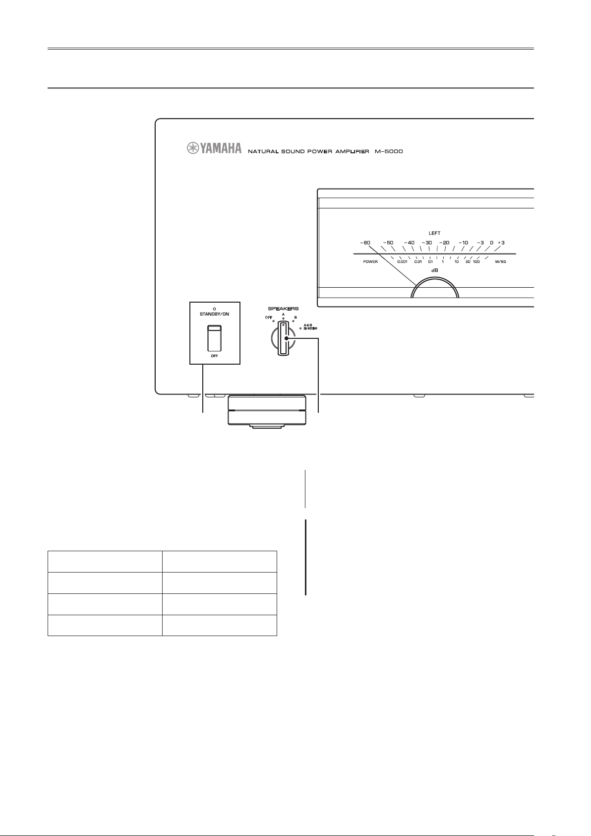
Front panel
AMPLIFIER
NATURAL SOUND
SPEAKERS
OFF
POWER
A
B
A+B
BI
WIRING
A.
STANDBY/ON/OFF (Power)
switch/indicator
Turns the power to the unit on or off.
STANDBY/ON
: Turns the power to the unit off.
OFF
On mode Lit brightly
Standby mode Lit dimly
O mode Off
The unit will enter standby mode in one of the following
events:
• If the unit is powered on but not operated for eight
hours while the auto power standby function is turned
on, or
• If you turn off the power to the device that is connected
to this unit’s TRIGGER IN jack.
For more information, refer to “G AUTO POWER
STANDBY switch” in the “Rear panel” section
(page 9) and to “Trigger connections” (page 13).
: Turns the power to the unit on.
Power status Indicator
Note
After you turn on the unit, it will take a few seconds before
the unit can reproduce sound.
NOTICE
If you plan not to use the unit for an extended period of
time, be sure to unplug the power cord from the AC outlet.
Even when the STANDBY/ON/OFF (Power) switch is turned
o (the power indicator is dark), a minimal amount of
electric current is still owing to the unit.
B.
SPEAKERS selector
Turns on or off two sets of speakers connected to the
SPEAKERS A and B terminals on the rear panel.
: Both sets of speakers are off.
OFF
: The set of speakers connected to the A terminal is on.
A
: The set of speakers connected to the B terminal is on.
B
A+B/BI-WIRING
: Both sets of speakers are on.
6
English
NOTICE
Make sure that the impedance of each speaker is
appropriate for the system conguration. For more
information, refer to “Basic speaker connections”
(page14), “Bi-wiring connections” (page18), “Biamp connections” (page20), and “Bridge connections”
(page22).
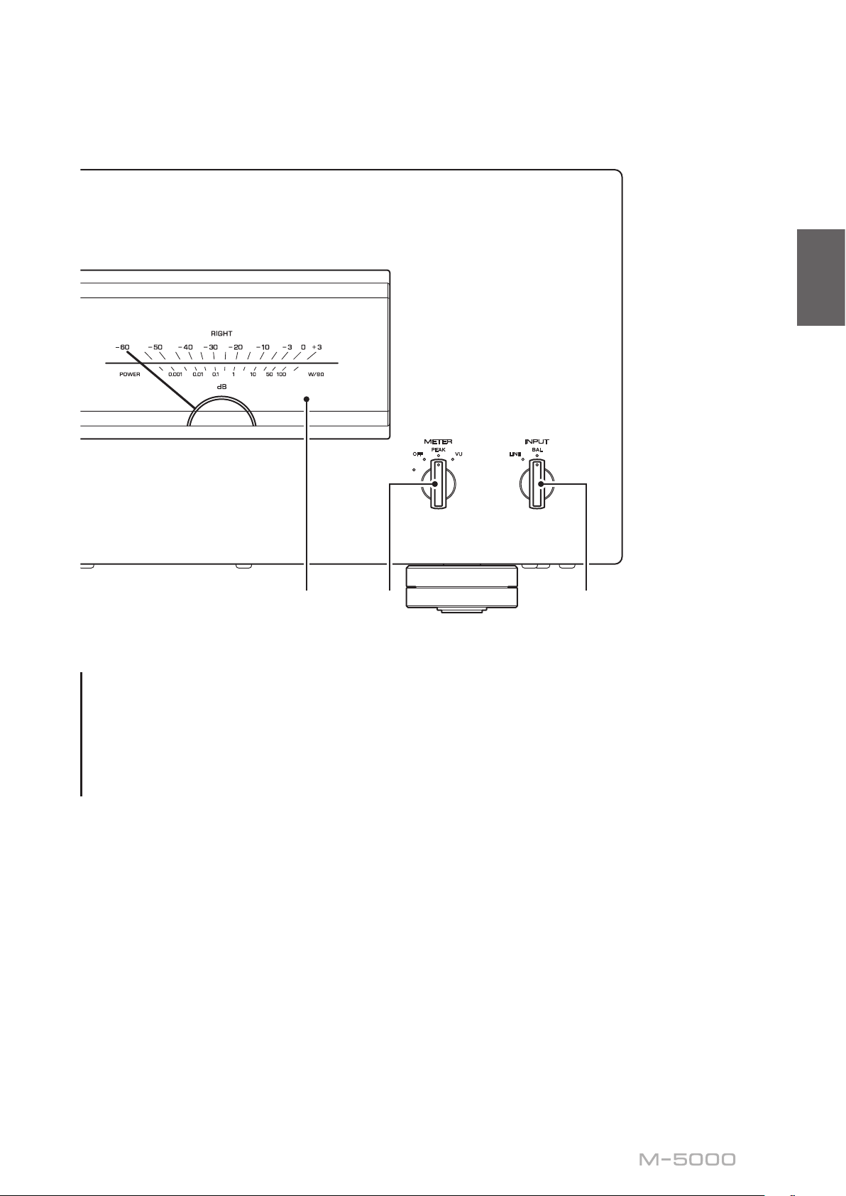
C.
Meter display (LEFT/RIGHT)
Indicates the audio output level of the left and right
channels.
D.
METER selector
Switches the meter display type to OFF, PEAK, or VU.
DIMMER
The brightness will change slowly between the brightest
and darkest (off). When you select the meter type by
turning the METER selector, the brightness at that point
will be used for the display.
OFF
: Adjusts the brightness of the meter display.
: Turns off meter operation and display illumination.
DIMMER
OFF
METER
PEAK
VU
: Switches the meter display type to a peak
PEAK
LINE
INPUT
BAL
level meter. The peak level meter shows the highest
instantaneous level of an audio output signal.
: Switches the meter display type to a VU (Volume
VU
Unit) level meter. The VU level meter shows an effective
audio output value that represents the way sound is
perceived by human ears.
E.
INPUT selector
Enables you to select jacks to play back an audio source.
: Audio source input from the LINE jacks will be
LINE
played back.
: Audio source input from the BAL jacks will be
BAL
played back.
7
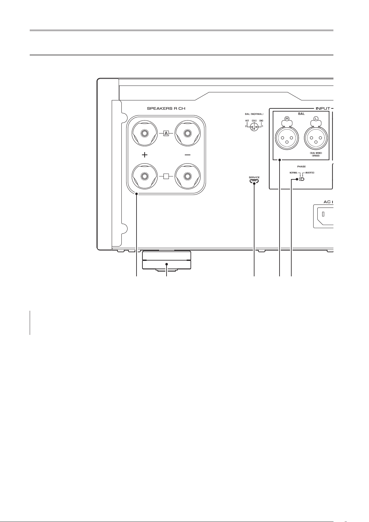
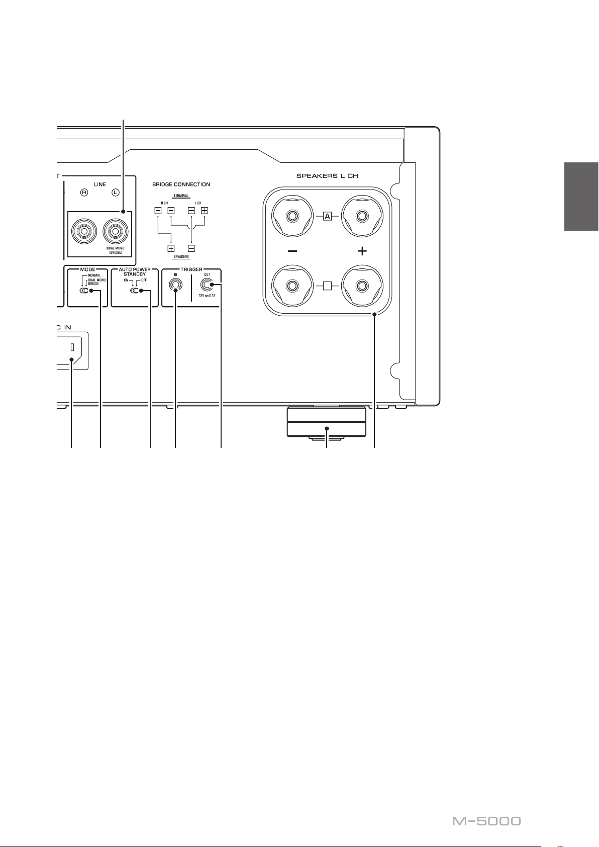
Rear panel
B
Note
For information regarding the connection procedure, refer
to “Connections” (page11).
A.
SPEAKERS R CH output terminals
B.
SPEAKERS L CH output terminals
Use the included speaker cables to connect speakers to
the terminals. For information regarding the connection
procedure, refer to “Connections” (page 11).
C.
BAL input jacks
These are XLR-type balanced input jacks. Connect your
preamplier here. Set the PHASE selector appropriately
for the connected preamplier.
D.
PHASE selector
Sets the position (polarity) of the HOT pin at the BAL
input jacks according to the connected preamplier. For
more information, refer to “Balanced and unbalanced
connections” (page 10).
NORMAL
INVERTED
Refer to the instruction manual for the connected
component to nd out the position of the HOT pin at the
balanced output jacks on the component.
E.
These are RCA-type unbalanced input jacks. Connect
your preamplier here.
: Pin #2 is specied as HOT.
: Pin #3 is specied as HOT.
LINE input jacks
8
English
B
F.
MODE selector
Switches the speaker output between stereo and
monaural. For more information, refer to “Basic speaker
connections” (page 14), “Bi-wiring connections”
(page 18), “Bi-amp connections” (page 20), and
“Bridge connections” (page 22).
NORMAL
the standard setting.
DUAL MONO/BRIDGE
amplier. Select this setting for bi-amp or bridge
connections.
G.
ON
is powered on but not operated for eight hours. This
function is disabled if the system cable is connected to
the TRIGGER IN jack.
OFF
: The unit is used as a stereo amplier. This is
: The unit is used as a monaural
AUTO POWER STANDBY switch
: The unit enters standby mode automatically if it
: The unit does not enter standby mode automatically.
H.
TRIGGER IN jack
I.
TRIGGER OUT jack
Used to connect a component that supports the trigger
function so that you can control the unit’s power on and
off from that component. For more information, refer to
“Trigger connections” (page 13).
J.
SERVICE jack
This jack is used to test the product.
K.
AC IN jack
Connect the supplied power cord here. For more
information, refer to “Connecting the power cord”
(page 24).
L.
Feet
If the unit is unstable, adjust the height of the feet as
needed by rotating them.
9
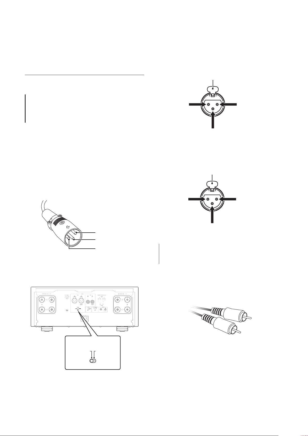
Balanced and unbalanced connections
This unit features balanced input jacks (BAL) and
unbalanced input jacks (LINE).
If the PHASE selector is set to NORMAL, pin #2
becomes HOT.
Lever
NOTICE
Do not use balanced and unbalanced connections between
two components simultaneously. Doing so would create a
ground loop that could generate static and noise.
Balanced connection
A balanced connection is a great advantage against
external noise. For a balanced connection, use a cable
with male XLR connectors. When connecting a cable, be
sure to align the pins on the connector with the holes on
the jack, and then insert the connector into the jack until
you hear a click. To remove the cable, while pressing
and holding down the lever on the BAL jack, pull out the
male XLR connector from the jack.
Pin #2
Pin #3
Pin #1
When making a balanced connection, you must set the
polarity correctly. To set the polarity, use the PHASE
selector on the rear panel.
2: hot
3: cold
1: ground (earth)
If the PHASE selector is set to INVERTED, pin #3
becomes HOT.
Lever
2: cold
3: hot
1: ground (earth)
Note
Select NORMAL (pin #2 is HOT) for a Yamaha player or
preamplier.
Unbalanced connection
For an unbalanced connection, use RCA-type pin cables.
They do not transmit phase information.
10
B
PHASE
NORMAL
INVERTED
B

Connections
This section explains how to connect the unit
to a preamplier and speakers.
English
CAUTION
Turn o the power to all components before making any connections.
NOTICE
Before you connect external components, read and follow the instruction manuals for those components. Otherwise, this unit or
external components might malfunction.
11
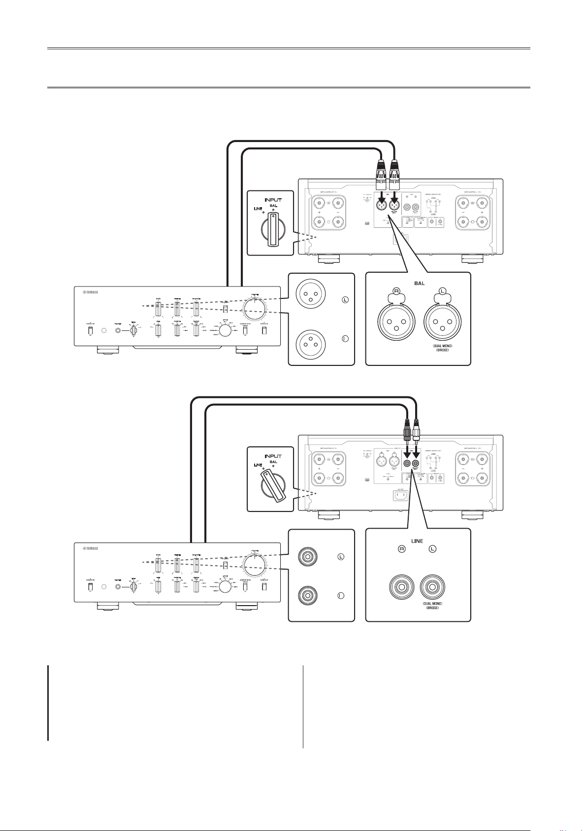
Connecting a preamplier
Connect your preamplier to the unit’s input jacks. For this connection, use XLR-type balanced cables or RCA-type
unbalanced cables.
Balanced connection
M-5000
Front panel
XLR-type balanced cable
Preamplier
LINE
INPUT
BAL
B
BAL
R
B
Unbalanced connection
RCA-type pin cable
Preamplier
NOTICE
The unit’s volume level is xed. Do not connect a
component that does not feature volume adjustment to
the unit’s input jacks. Otherwise, a loud sound might be
emitted, resulting in malfunction of the unit or damage to
the speakers.
Front panel
INPUT
BAL
LINE
M-5000
B
LINE 1
R
B
Note
• If the preamplier supports both balanced and
unbalanced connections, use a balanced connection.
• Do not use balanced and unbalanced connections
between two components simultaneously. Doing so
would create a ground loop that could generate static and
noise.
12
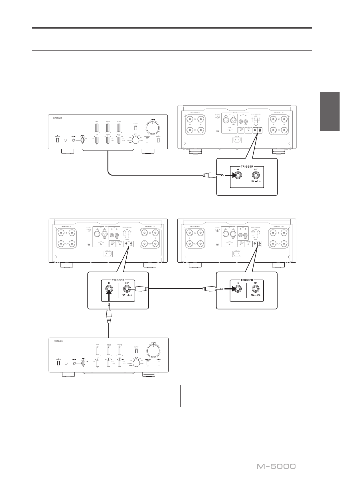
Trigger connections
B
B
M-5000
M-5000M-5000
You can control the unit’s power on and off in sync with a connected Yamaha component, such as a preamplier or AV
receiver.
Use the supplied system cable to make connections as shown in the following diagram.
Example (one M-5000 unit is used)
Preamplier, etc.
B
System cable
Example (two M-5000 units are used)
B
English
B
B
System cable
Preamplier, etc.
To control the unit in a trigger connection conguration,
set the STANDBY/ON/OFF (Power) switch to
STANDBY/ON.
When the power to the connected component is turned
on, the power to this unit is also turned on. When the
power to the connected component is turned off, this unit
enters standby mode.
System cable
B
B
Note
When the power switch on this unit is turned OFF, the
power to the unit will not be triggered.
13
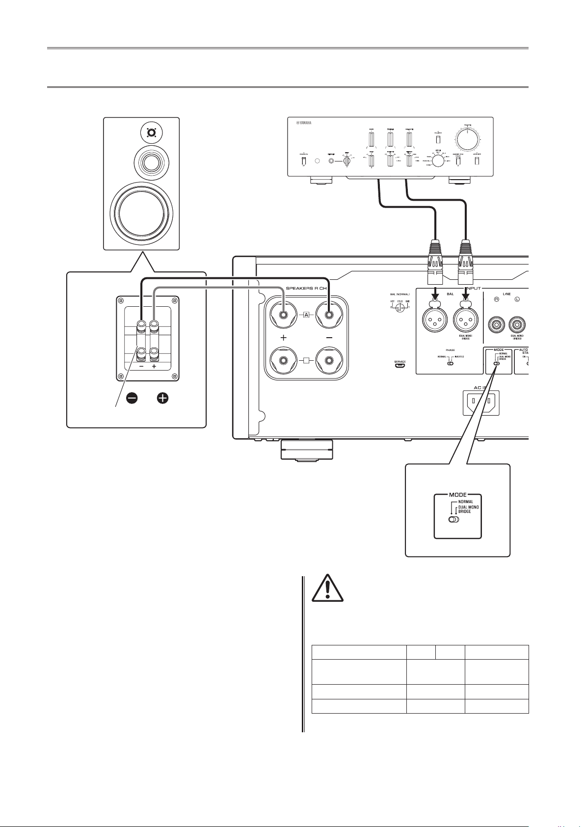
Basic speaker connections
SPEAKERS
OFF
A
B
R channel
High
Low
R channel
Preamplier
R channel L channel
R channel signal L channel signal
B
Shorting bar
Turn o the power to the unit and all
1
connected components.
Set the MODE selector on the rear panel to
2
NORMAL.
Set the SPEAKERS selector on the front
3
panel to A, B, or A+B BI-WIRING.
The diagram shows the selector set to A.
MODE selector
MODE: NORMAL
CAUTION
Be sure to use speakers that feature the impedance shown
in the table below.
Speaker impedance
SPEAKERS selector A B A+B
Basic connection/
Bi-wiring connection
Bi-amp connection 4Ω or higher 8Ω or higher
Bridge connection 8Ω or higher 16Ω or higher*
4Ω or higher 8Ω or higher
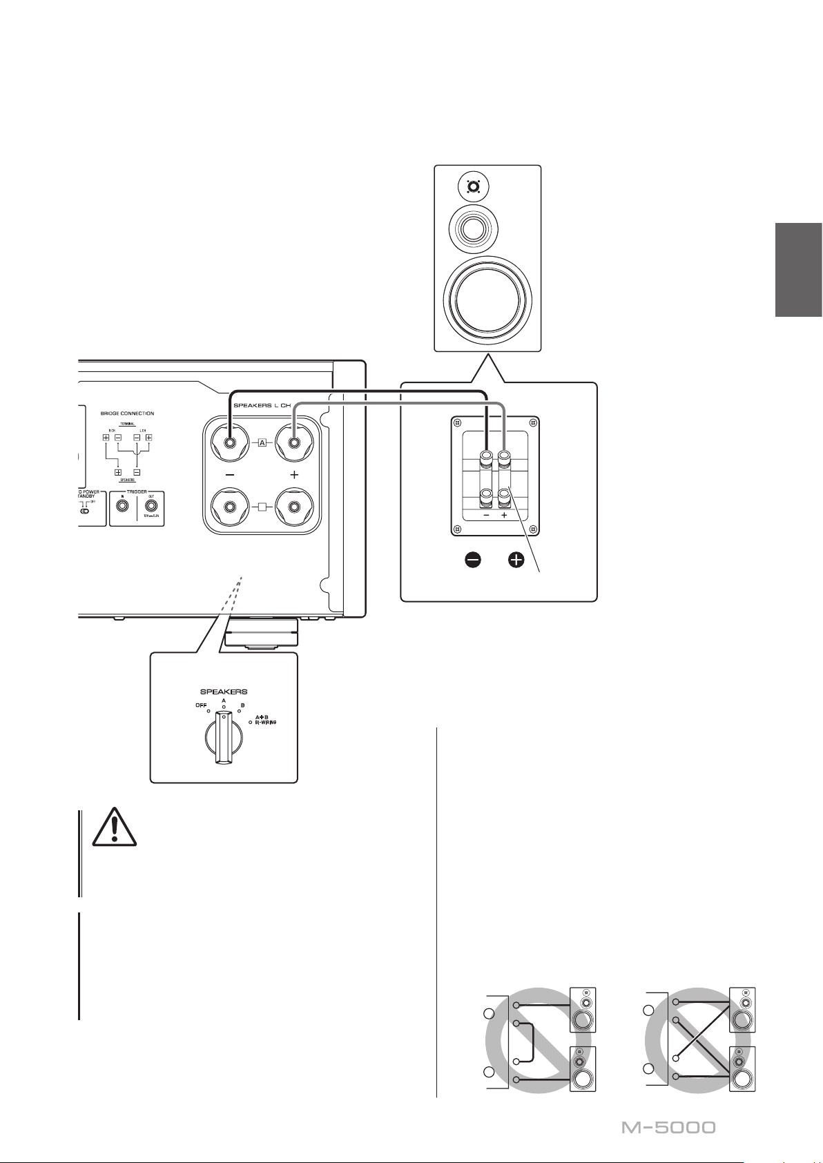
Connect the power amplier to the “+” and
4
“−” terminals of the speakers.
14
* Excluding models for U.S.A. and Canada
M-5000
+
–
+
–
L
R
+
–
+
–
L
R
L channel
English
L channel
High
B
SPEAKERS selector
(front panel)
SPEAKERS
A
OFF
B
A+B
BI
WIRING
CAUTION
Before turning the power back on to the source
component, rst lower the volume level on that
component.
NOTICE
• Do not let the bare speaker wires touch each other, nor
let them touch any metal part of this unit. Otherwise, the
unit and/or the speakers might be damaged.
• Do not connect an active subwoofer to this unit. Connect
the subwoofer to the preamplier.
Low
Shorting bar
Note
• All connections must be correct: L (left) to L, R (right) to
R, “+” to “+”, and “−” to “−”. If the connections are faulty,
no sound will be heard from the speakers. Also, if the
polarity of the speaker connections is incorrect, the
sound will be unnatural and lack bass.
• Because this power amplier is of the oating balanced
type, the following types of connections are not possible.
- Connecting between two “+” (or two “−”) terminals of
the left and right channels (Fig. 1).
- Connecting each “−” terminal of the unit’s left and
right channels to the opposite channel speakers
(cross connection, Fig. 2).
- Connecting the left/right channel “−” terminals (or
accidentally allowing them to come in contact) with
the metal part of the rear panel of this unit.
Figure
1
+
L
–
Figure
2
+
L
–
–
R
+
–
R
+
15
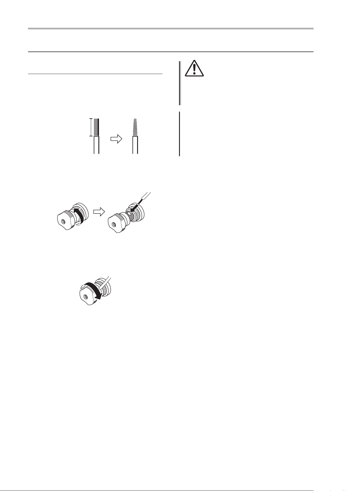
Connecting speaker cables
Using standard speaker cables
Remove approximately 10 mm (0.4 in) of
1
insulation from the end of each speaker
cable, and twist the exposed wires
together tightly to prevent short circuits.
10 mm (0.4 in)
Unscrew the knob on each SPEAKERS
2
terminal, and then insert the bare wire into
the side hole on the terminal.
CAUTION
• Do not loosen the knob excessively. Otherwise, the knob
might come o and a child might swallow it accidentally.
• To reduce the risk of electric shock, do not touch the
SPEAKERS terminals while the power to the unit is on.
NOTICE
If the SPEAKERS terminals come into contact with a metallic
rack, a short circuit might occur, resulting in damage to this
unit. When installing the unit in a rack, maintain a sucient
clearance to prevent the SPEAKERS terminals from coming
into contact with the rack.
Tighten the knob.
3
Diameter of the speaker cable
wire hole: 6.0 mm (0.24 in)
16
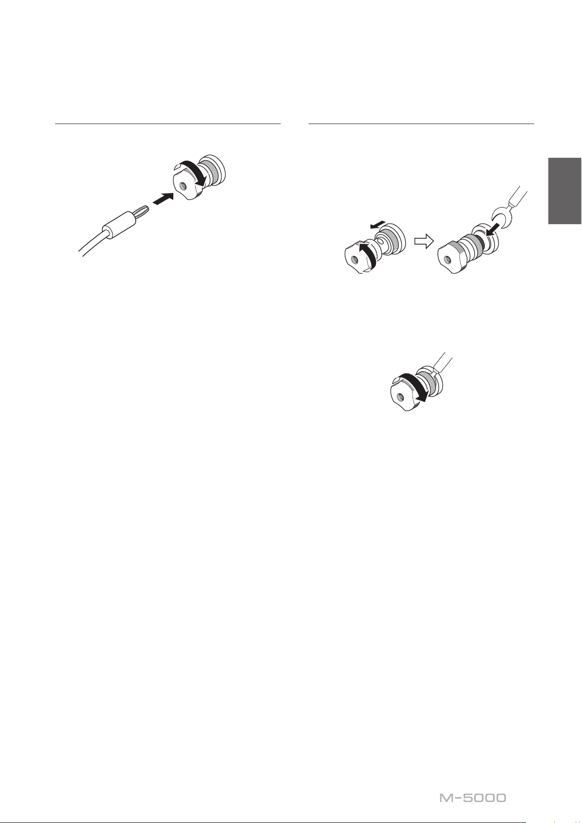
Using banana plug cables
First, tighten the knob, and then insert the banana plug
into the head of the knob.
Using Y-shaped lug cables
Unscrew the knob, and then sandwich the
1
Y-shaped lug between the ring part and
base of the terminal.
Diameter of the banana
plug hole: 5.5 mm (0.22 in)
Y-shaped lug
English
Slide
Thickness of the
terminal core: 5.0 mm (0.20 in)
Tighten the knob.
2
17
SPEAKERS
OFF
A
B
R channel
High
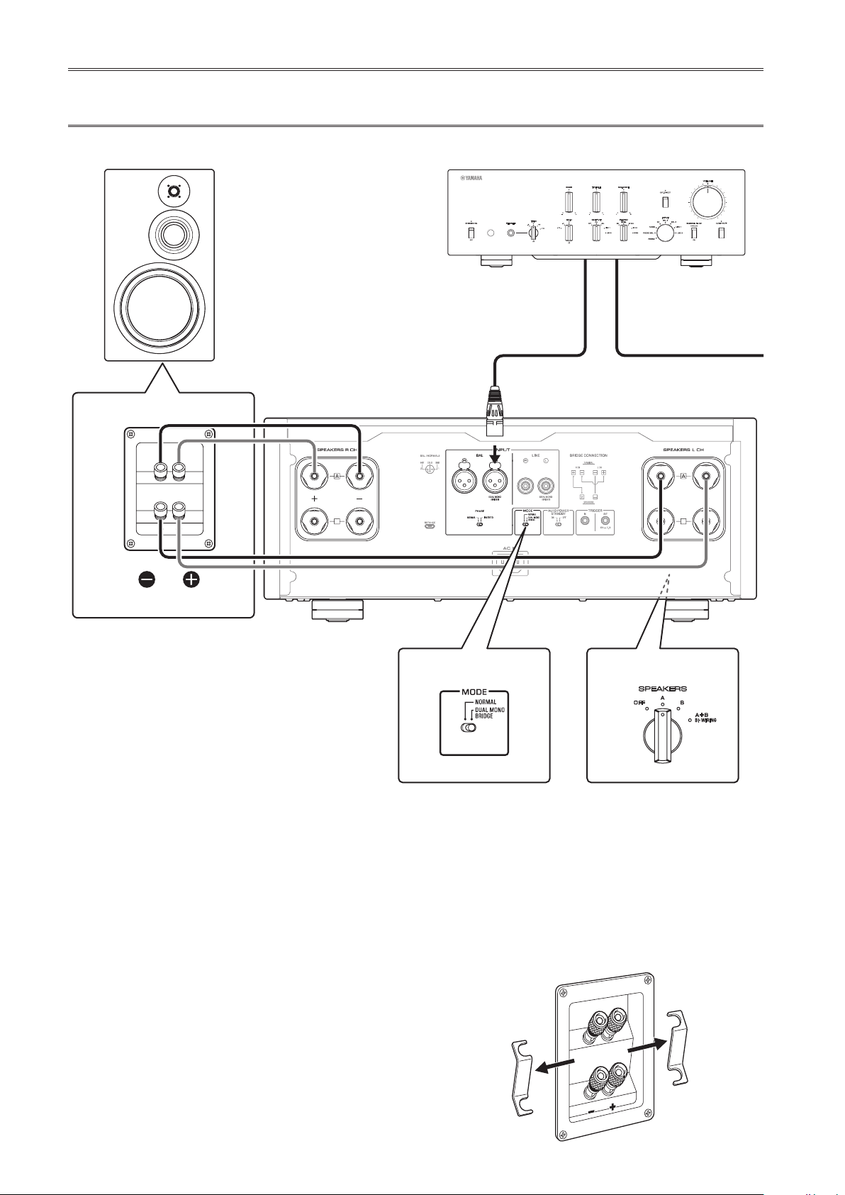
Bi-wiring connections
PreamplierR channel
R channel L channel
R channel signal L channel signal
Low
Remove the shorting bar.
To bi-wire your speakers, separate cables are used to
connect the mid/high-frequency speaker driver (tweeter)
and the low-frequency driver (woofer) on each bi-
wireable speaker to the amplier. Running separate
cables from the amplier can have a profound impact on
relieving the tweeter circuit from the back ush of EMF
(electromotive force) generated by the woofer’s voice
coil, resulting in less interference between HF and LF
ranges and better sound quality.
You need to use speakers that feature two sets of
terminals (total of four) that allow each speaker to be split
into two sections (low-frequency and mid/high-frequency
ranges).
B
MODE selector
MODE: NORMAL
Remove the shorting bars or bridges on
2
the speakers.
The LPF (low pass lter) and HPF (high pass
lter) crossovers will be separated.
Turn o the power to the unit and all
1
connected components.
18

M-5000
L channel
English
L channel
High
B
SPEAKERS selector
(front panel)
SPEAKERS
A
OFF
B
A+B
BI
WIRING
Connect the power amplier to the
3
speakers.
For each channel speaker, connect the cables
from the speaker’s mid/high range terminals
to the amplier’s SPEAKERS A jacks of the
corresponding channel, and from the speaker’s
low range terminals to the amplier’s SPEAKERS
B jacks of the corresponding channel respectively.
Set the MODE selector on the rear panel to
4
NORMAL.
Low
Remove the shorting bar.
CAUTION
Be sure to use speakers that feature the impedance shown
in the table below.
Speaker impedance
SPEAKERS selector A B A+B
Basic connection/
Bi-wiring connection
Bi-amp connection 4Ω or higher 8Ω or higher
Bridge connection 8Ω or higher 16Ω or higher*
* Excluding models for U.S.A. and Canada
4Ω or higher 8Ω or higher
Set the SPEAKERS selector on the front
5
panel to A+B BI-WIRING.
CAUTION
Before turning the power back on to the source component,
rst lower the volume level on that component.
19
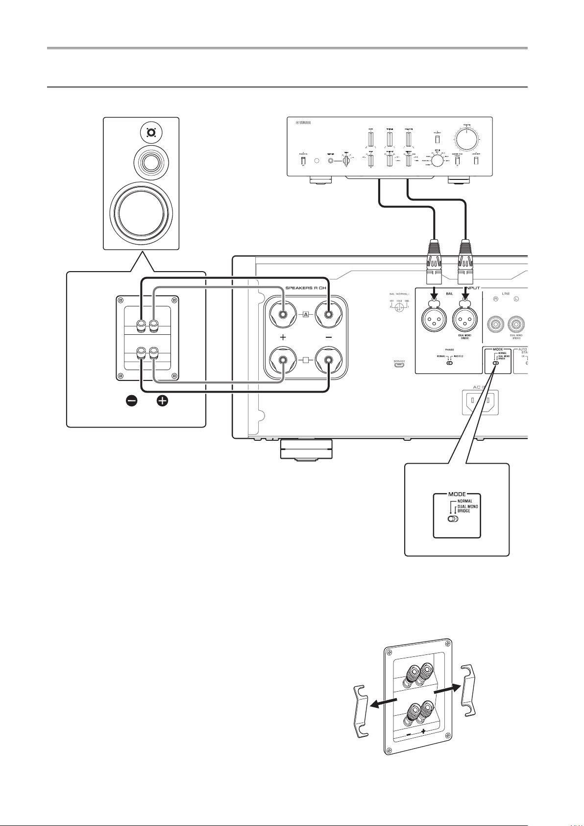
Bi-amp connections
B
MODE: DUAL MONO/BRIDGE
PreamplierR channel
R channel L channel
R channel signal L channel signal
R channel
High
Low
Remove the shorting bar.
M-5000
B
MODE selector
MODE: DUAL MONO/BRIDGE
SPEAKERS selector
(front panel)
SPEAKERS
OFF
B
A
B
A+B
BI
WIRING
To congure a bi-amp stereo system, you need two
M-5000 units.
The M-5000 features two built-in ampliers. Each of
these amps is connected to the mid/high-frequency
speaker driver (tweeter) and the low-frequency driver
(woofer) on the speaker of the corresponding channel.
You need to use speakers that feature two sets of
terminals (total of four) that allow each speaker to be split
into two sections (low-frequency and mid/high-frequency
ranges). Bi-amping speakers can prevent the back ush of
EMF (electromotive force) generated by the woofer from
affecting the signal, resulting in improved sound quality
in some cases.
Connect the input source to the L-channel input jacks on
both M-5000 units.
20
Turn o the power to the unit and all
1
connected components.
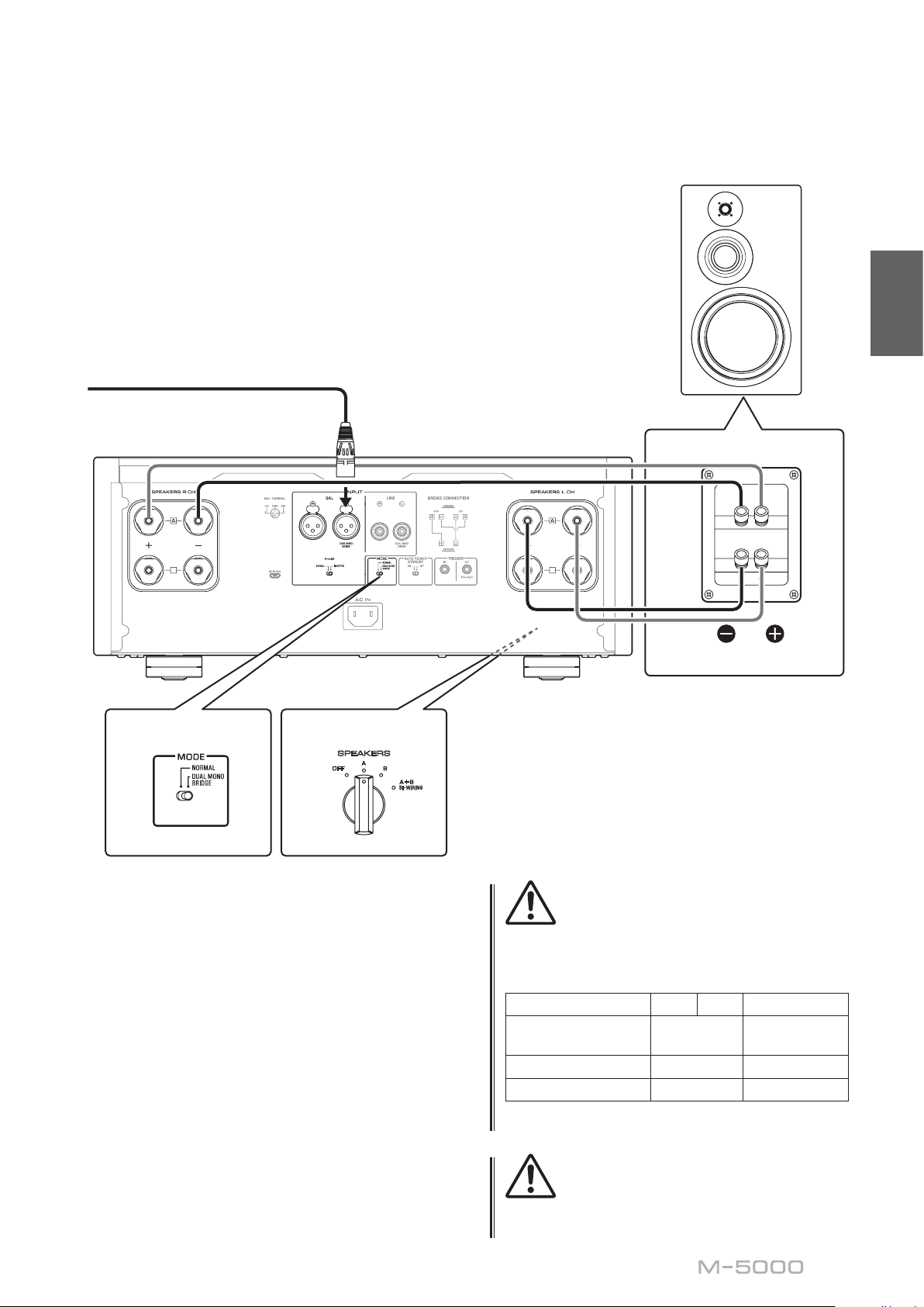
Remove the shorting bars or bridges on
2
the speakers.
The LPF (low pass lter) and HPF (high pass
lter) crossovers will be separated.
L channel
English
B
MODE selector
MODE: DUAL MONO/BRIDGE
SPEAKERS selector
(front panel)
SPEAKERS
A
OFF
B
A+B
BI
WIRING
B
M-5000
L channel
High
Low
Remove the shorting bar.
Set the MODE selector on the rear panel to
3
DUAL MONO/BRIDGE.
Set the SPEAKERS selector on the front
4
panel to A, B, or A+B BI-WIRING.
The diagram shows the selector set to A.
Connect the power amplier (this unit) to
5
the speakers.
For each channel speaker, connect the cables
from the speaker’s mid/high range terminals to
the amplier A jacks for the SPEAKERS R CH,
and from the speaker’s low range terminals to the
amplier A jacks for the SPEAKERS L CH.
CAUTION
Be sure to use speakers that feature the impedance shown
in the table below.
Speaker impedance
SPEAKERS selector A B A+B
Basic connection/
Bi-wiring connection
Bi-amp connection 4Ω or higher 8Ω or higher
Bridge connection 8Ω or higher 16Ω or higher*
* Excluding models for U.S.A. and Canada
4Ω or higher 8Ω or higher
CAUTION
Before turning the power back on to the source component,
rst lower the volume level on that component.
21
 Loading...