

YAMAHA Z300A, LZ300A PARTS CATALOGUE

Z300A
LZ300A
292211
SUPPLEMENTARY
SERVICE MANUAL
6D0-28197-3F-1X
NOTICE
This Supplementary Service Manual has been prepared to introduce new service and new data
information for the Z300 and LZ300 which are based on the Z250 and LZ250. For complete information on service procedures, it is necessary to use this Supplementary Service Manual together with
the following manual.
Z250D, LZ250D SERVICE MANUAL: 60V-28197-3E-11
Important information
Particularly important information is distinguished in this manual by the following notations:
The Safety Alert Symbol means ATTENTION! BECOME ALERT! YOUR SAFETY IS
INVOLVED!
WARNING
Failure to follow WARNING instructions could result in severe injury or death to the machine
operator, a bystander, or a person inspecting or repairing the outboard motor.
CAUTION:
A CAUTION indicates special precautions that must be taken to avoid damage to the outboard motor.
NOTE:
A NOTE provides key information to make procedures easier or clearer.
CAUTION:
USE UNLEADED STRAIGHT GASOLINE ONLY
• Gasoline containing lead can cause performance loss and engine damage.
• Do not use gasoline mixed with oil during the break-in period or anytime thereafter.
YAMALUBE 2-STROKE OUTBOARD OIL IS RECOMMENDED.
1
Z300A, LZ300A
SUPPLEMENTARY SERVICE MANUAL
©2003 by Yamaha Motor Co., Ltd.
1st Edition, July 2003
All rights reserved.
Any reprinting or unauthorized use
without the written permission of
Yamaha Motor Co., Ltd.
is expressly prohibited.
Printed in the Netherlands
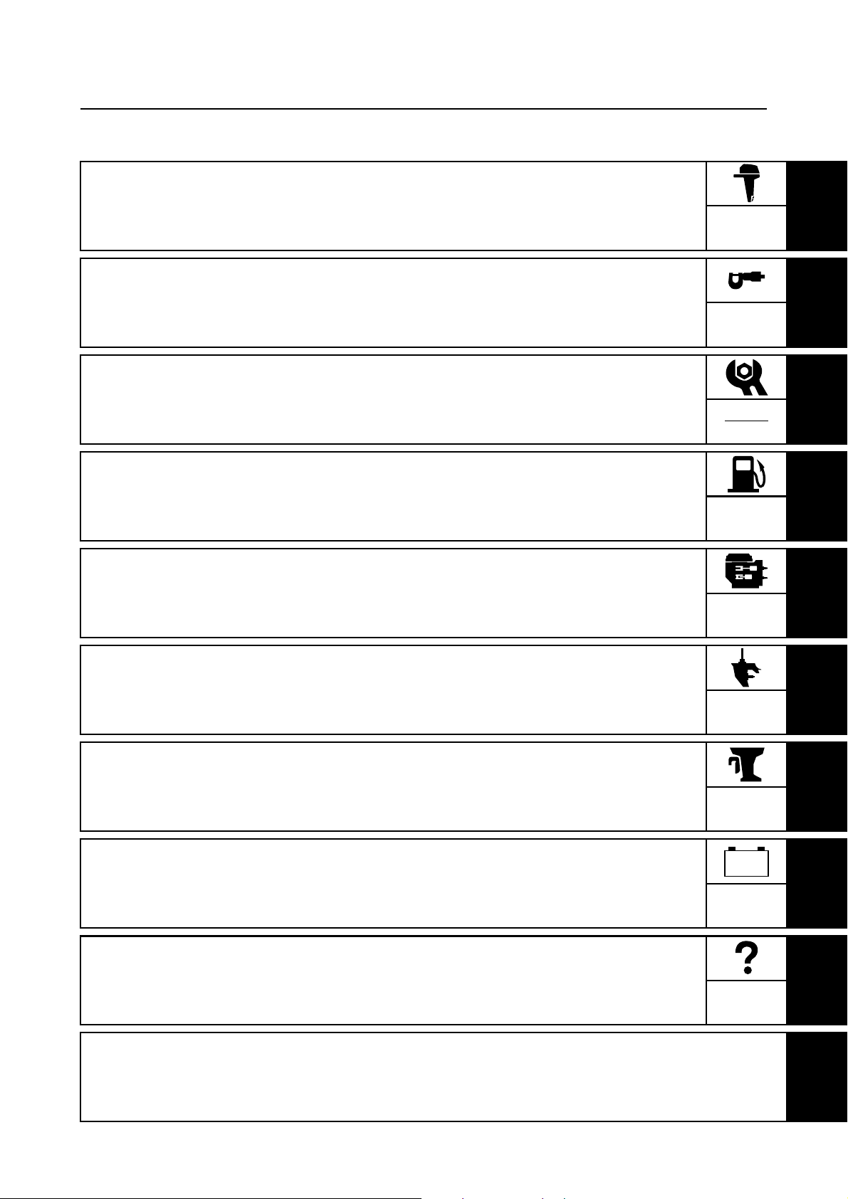
Contents
General information
Specifications
Periodic checks and adjustments
Fuel system
Power unit
GEN
INFO
SPEC
CHK
ADJ
FUEL
POWR
1
2
3
4
5
Lower unit
Bracket unit
Electrical systems
Troubleshooting
Index
LOWR
BRKT
–+
ELEC
TRBL
SHTG
6
7
8
9

General information
How to use this manual....................................................................................1
Manual format............................................................................................... 1
Symbols........................................................................................................ 2
Identification...................................................................................................... 3
Applicable models ........................................................................................ 3
Serial number ...............................................................................................3
Features and benefits.......................................................................................4
Crankcase and cylinders ..............................................................................4
Intake system ............................................................................................... 6
Upper case ...................................................................................................8
Lower case ...................................................................................................9
ECM (Electronic Control Module) ............................................................... 10
Wiring harness connector holder................................................................ 10
Propeller selection..........................................................................................11
Propeller size.............................................................................................. 11
Selection..................................................................................................... 11
Predelivery checks .........................................................................................12
Checking the fuel system ........................................................................... 12
Checking the gear oil level ......................................................................... 12
Checking the engine oil level......................................................................12
Checking the battery................................................................................... 12
Checking the outboard motor mounting height........................................... 13
Checking the remote control cables ........................................................... 13
Checking the steering system .................................................................... 14
Checking the gear shift and throttle operation............................................14
Checking the power trim and tilt system..................................................... 14
Checking the engine start switch and engine stop lanyard switch ............. 14
Checking the cooling water pilot hole ......................................................... 15
Test run ...................................................................................................... 15
Break-in ......................................................................................................15
After test run ............................................................................................... 15
6D03F1X

Specifications
General specifications.................................................................................... 16
Maintenance specifications ........................................................................... 18
Power unit................................................................................................... 18
Lower unit ................................................................................................... 20
Electrical ..................................................................................................... 20
Dimensions................................................................................................. 23
Tightening torques..........................................................................................25
Specified torques........................................................................................ 25
General torques.......................................................................................... 27
Periodic checks and adjustments
Special service tools ......................................................................................28
Maintenance interval chart............................................................................. 31
Oil injection system ........................................................................................ 32
Adjusting the oil pump link rod.................................................................... 32
Lower unit........................................................................................................ 32
Checking the lower unit for air leakage ...................................................... 32
General............................................................................................................. 33
Lubricating the outboard motor................................................................... 33
Fuel system
Fuel filter.......................................................................................................... 35
6D03F1X

Power unit
Power unit........................................................................................................ 36
Removing the power unit............................................................................ 37
Crankcase........................................................................................................39
Removing the crankcase covers ................................................................ 40
Installing the crankcase covers ..................................................................40
Installing the power unit.............................................................................. 40
Lower unit
Propeller shaft housing (regular rotation model) ........................................ 43
Shimming (regular rotation model) ............................................................... 45
Selecting the pinion shims.......................................................................... 46
Backlash (regular rotation model)................................................................. 47
Measuring the forward and reverse gear backlash ....................................47
Propeller shaft housing (counter rotation model) ....................................... 50
Drive shaft and lower case (counter rotation model) .................................. 52
Disassembling the reverse gear ................................................................. 54
Assembling the lower case......................................................................... 54
Shimming (counter rotation model) .............................................................. 56
Selecting the pinion shims.......................................................................... 57
Backlash (counter rotation model)................................................................ 58
Measuring the forward and reverse gear backlash ....................................58
Bracket unit
Bottom cowling ............................................................................................... 61
Upper case, steering arm, swivel bracket, and clamp brackets.................64
Power trim and tilt unit ................................................................................... 69
Checking the hydraulic pressure ................................................................ 69
6D03F1X

Electrical systems
Electrical components.................................................................................... 72
Port view..................................................................................................... 72
Top view .....................................................................................................73
Troubleshooting
Self-diagnosis..................................................................................................74
Diagnosing the electronic control system................................................... 74
Wiring diagram
6D03F1X
GEN
INFO
General information
How to use this manual
Only chapters containing revisions or additional items in the base manual have been included in this
manual.
All special service tools introduced in this manual are mentioned in Chapter 3.
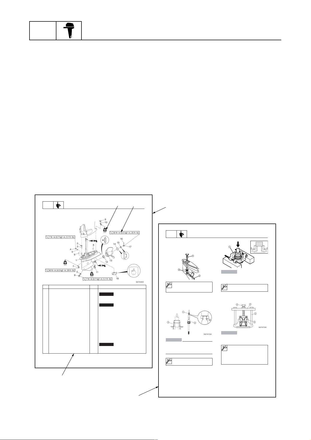
Manual format
The format of this manual has been designed to make service procedures clear and easy to understand. Use the information below as a guide for effective and quality service.
1
Parts are shown and detailed in an exploded diagram and are listed in the components list.
2
Tightening torque specifications are provided in the exploded diagrams and after a numbered
step with tightening instructions.
3
Symbols are used to indicate important aspects of a procedure, such as the grade of lubricant
and lubrication point.
4
The components list consists of part names and part quantities, as well as bolt and screw dimensions.
5
Service points regarding removal, checking, and installation are shown in individual illustrations
to explain the relevant procedure.
1
LOWR
Lower unit
No. Part name Q’ty Remarks
1 Lower unit 1
2 Plastic tie 1
3Hose 1
4 Check screw 1
5 Gasket 2
6 Dowel pin 2
7 Bolt 4 M10 40 mm
8 Drain screw 1
9Grommet 1
10 Bolt 1 M10 45 mm
11 Bolt 1 M8 60 mm
12 Thrust washer 1
13 Propeller 1
14 Washer 1
15 Washer 1
16 Cotter pin 1
17 Propeller nut 1
18 Trim tab 1
6-5
Lower unit
Not reusable
Not reusable
Not reusable
3
4
2
62Y5A11
1
LOWR
Removing the drive shaft
1. Remove the drive shaft assembly and
pinion, and then pull out the forward
gear.
Disassembling the drive shaft
1. Install the pinion nut 1, tighten it finger
tight, and then remove the drive shaft
bearing 2 using a press.
CAUTION:
• Do not press the drive shaft threads
directly.
• Do not reuse the bearing, always
replace it with a new one.
Disassembling the forward gear
1. Remove the taper roller bearing from the
forward gear using a press.
Lower unit
S62Y6850K
Drive shaft holder 4 1: 90890-06518
Pinion nut holder 2: 90890-06505
Socket adapter 2 3: 90890-06507
Bearing inner race attachment 3:
90890-06639
CAUTION:
Do not reuse the bearing, always replace
it with a new one.
Bearing separator 1: 90890-06534
2. Remove the needle bearing from the forward gear.
CAUTION:
Do not reuse the bearing, always replace
it with a new one.
a
Stopper guide plate 2: 90890-06501
Stopper guide stand 3:
90890-06538
Bearing puller 4: 90890-06535
Bearing puller claw 1 5:
90890-06536
S62Y6740K
6-19
62Y5A11
5
1
6D03F1X
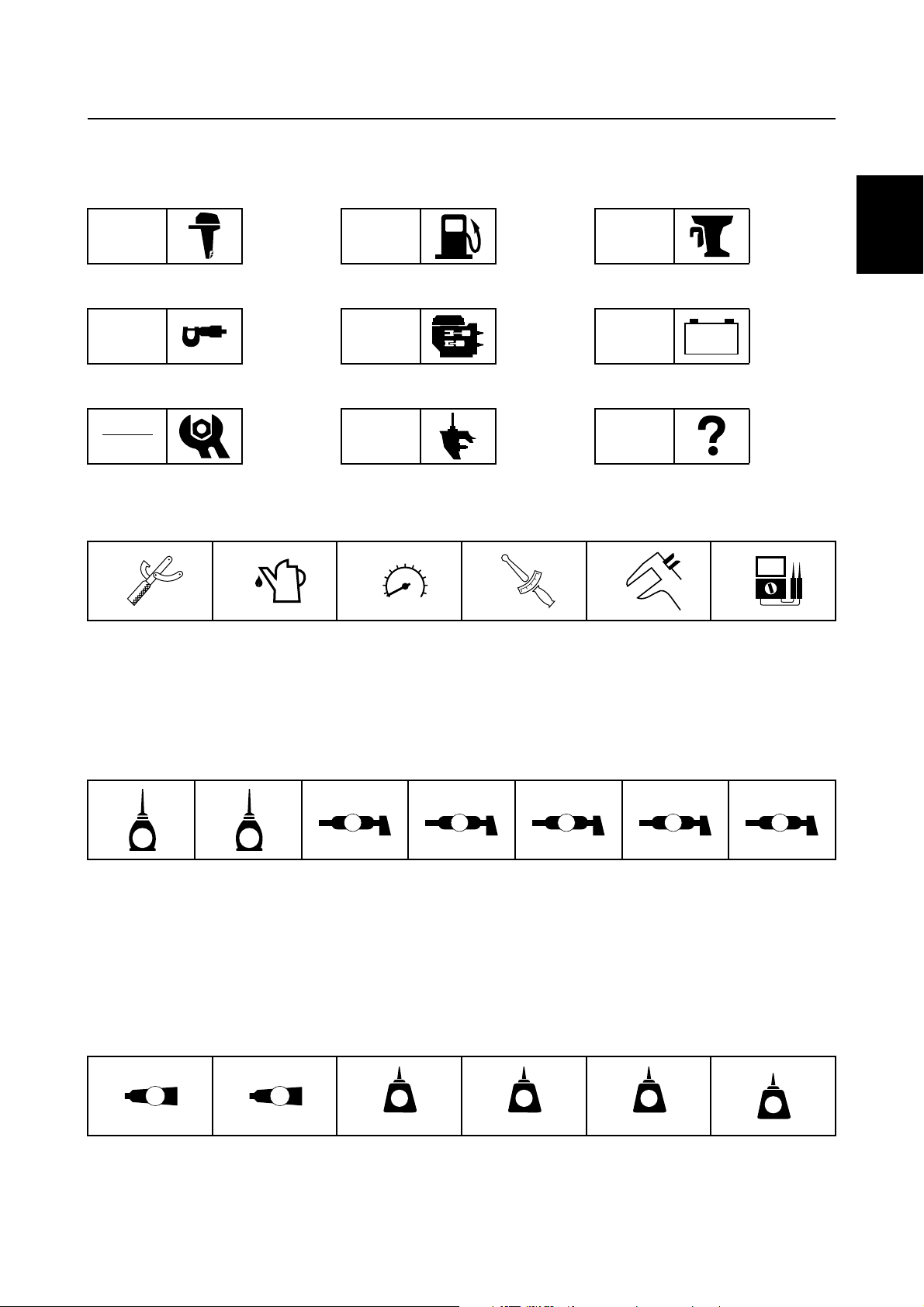
Symbols
T
R
.
.
D
242
LT
The symbols below are designed to indicate the content of a chapter.
How to use this manual
General information
GEN
INFO
Specifications
SPEC
Periodic checks and adjustments
CHK
ADJ
Symbols 1 to 6 indicate specific data.
123456
Fuel system
FUEL
Power unit
POWR
Lower unit
LOWR
Bracket unit
BRKT
Electrical systems
ELEC
Troubleshooting
– +
TRBL
SHTG
1
2
3
4
Special tool
1
Specified oil or fluid
2
Specified engine speed
3
Specified tightening torque
4
Symbols 7 to C in an exploded diagram indicate the grade of lubricant and the lubrication point.
7890ABC
A M
E G
Apply 2-stroke outboard motor oil
7
Apply gear oil
8
Apply water resistant grease (Yamaha grease A)
9
Apply molybdenum disulfide grease
0
Symbols D to I in an exploded diagram indicate the type of sealant or locking agent and the application point.
DEFGHI
GM
4
LT
271
Specified measurement
5
Specified electrical value
6
(resistance, voltage, electric current)
C I
Apply corrosion resistant grease
A
(Yamaha grease D)
Apply low temperature resistant grease
B
(Yamaha grease C)
Apply injector grease
C
LT
572
SS
5
6
7
8
9
Apply Gasket Maker
D
Apply Yamabond No. 4
E
Apply LOCTITE 271 (red)
F
6D03F1X
Apply LOCTITE 242 (blue)
G
Apply LOCTITE 572
H
Apply silicon sealant
I
2
GEN
INFO
General information
Identification
Applicable models
This manual covers the following models.
Applicable models
Z300AETO, LZ300AETO
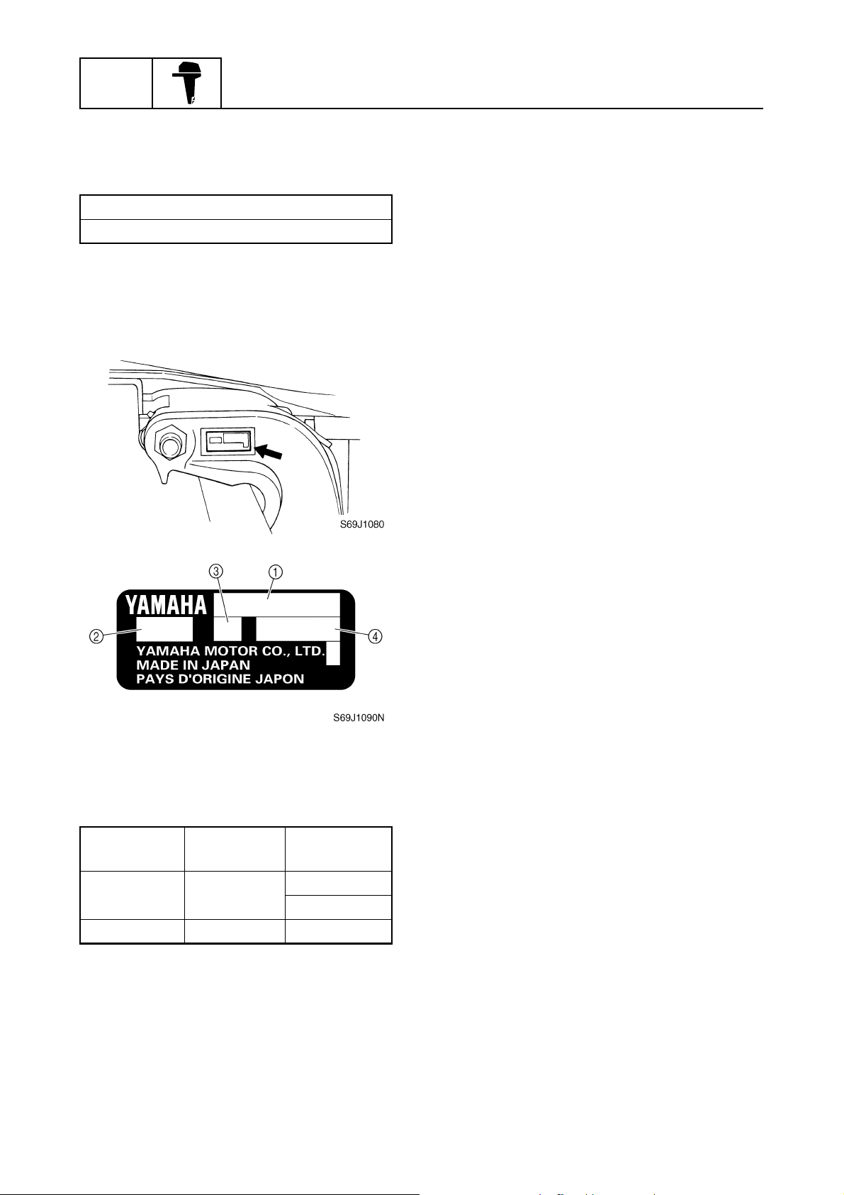
Serial number
The outboard motor serial number is
stamped on a label attached to the port
clamp bracket.
1
Model name
1
Approved model code
2
Transom height
3
Serial number
4
Model name
Approved
model code
Starting
serial No.
X: 1000001–
Z300AETO 6D0
U: 1000001–
LZ300AETO 6D1 X: 1000001–
3
6D03F1X
Identification / Features and benefits
Features and benefits
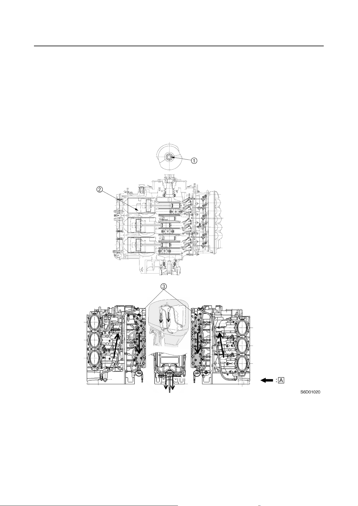
Crankcase and cylinders
The following modifications have been adopted to increase the output as compared to the Z250
power unit.
• The material of the crankshaft has been changed to a high-grade clean steel
bility against stress.
• Wider exhaust ports with planed-off edges have been adopted and the exhaust timing has been
changed to reduce the exchange loss of the exhaust gas.
• Cooling water jackets have been incorporated to the crankcase to increase engine-cooling ability.
*1: Steel with decreased nonmetallic inclusion content
(*1)
to increase dura-
1
Crankshaft identification
1
Identification mark: 2 mm (0.079 in) punch mark
Exhaust port
2
Crankcase water jackets
3
Water flow
È
6D03F1X
4
GEN
INFO
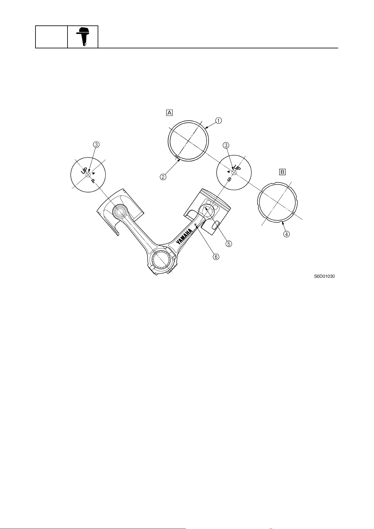
• Newly-forged lightweight pistons with a hard anodic coating on the piston pin boss have been
adopted to increase durability and reduce the inertia mass of the pistons.
• The top piston rings are made of steel and are ion-plated to increase durability.
• The heat treatments for the piston pins and connecting rods have been changed so that there is
multiphase carbonization to increase durability.
General information
Ion plating (chromium)
1
Identification mark: R
2
Identification mark: 6D0
3
Oil groove
4
Hard anodic coating
5
Identification mark
6
Top ring
È
Second ring
É
5
6D03F1X
Features and benefits
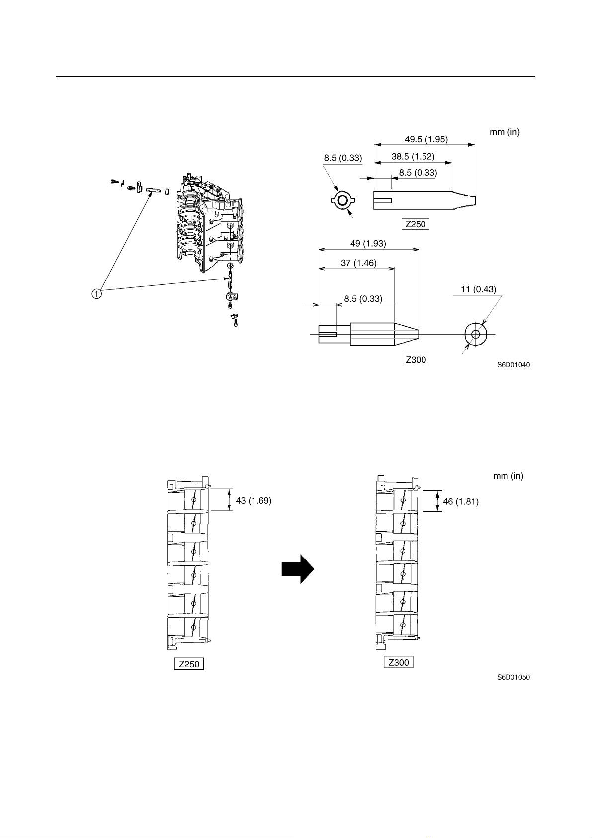
• The anti-corrosion anodes in the cooling water passages of the cylinder block are larger to
increase reliability and performance.
Anodes
1
Intake system
The openings in the throttle bodies were enlarged to a 46 mm (1.81 in) diameter to increase power
output.
6D03F1X
6
GEN
INFO
An oil groove has been added to each reed valve seat. Oil in the groove helps to reduce impact
when the reed valve contacts the reed valve seat.
The dimensions of the reed valve assembly are the same as those for the Z250.
General information
Oil groove
1
Identification mark: 6D0
2
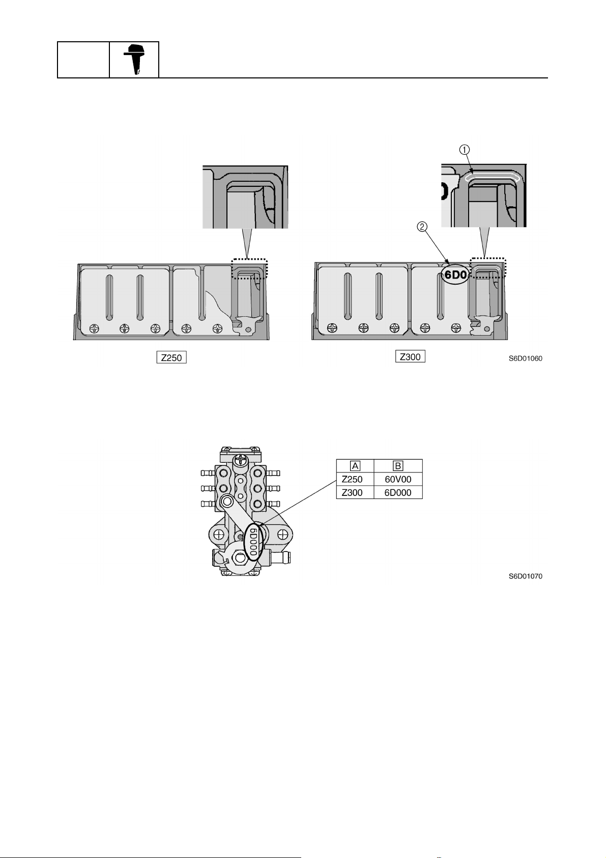
The oil pump has been newly designed to obtain optimal oil supply.
Model
È
Identification mark
É
7
6D03F1X
Features and benefits
Upper case
Water jackets have been incorporated to both sides of the lower part of the upper case. This structure reduces the heat transfer to the upper case from the exhaust gas.
The cooling water discharged from the water pump is supplied to the upper case around the muffler
from the pipe connected to the exhaust guide, flows down into the water jacket, and then drains to
the lower case.
Water jackets have been incorporated to the exhaust manifold to protect it from the high-temperature exhaust gas.
Fresh cooling water from the water pump accumulates in the water jacket, and then drains into the
muffler.
Muffler
1
Upper case
2
Gasket
3
Upper case water jacket
4
Lower case
5
Exhaust guide
6
Hose
7
Exhaust manifold
8
Water
9
Water pump
0
6D03F1X
Water flow
È
Exhaust passage
É
8
GEN
INFO
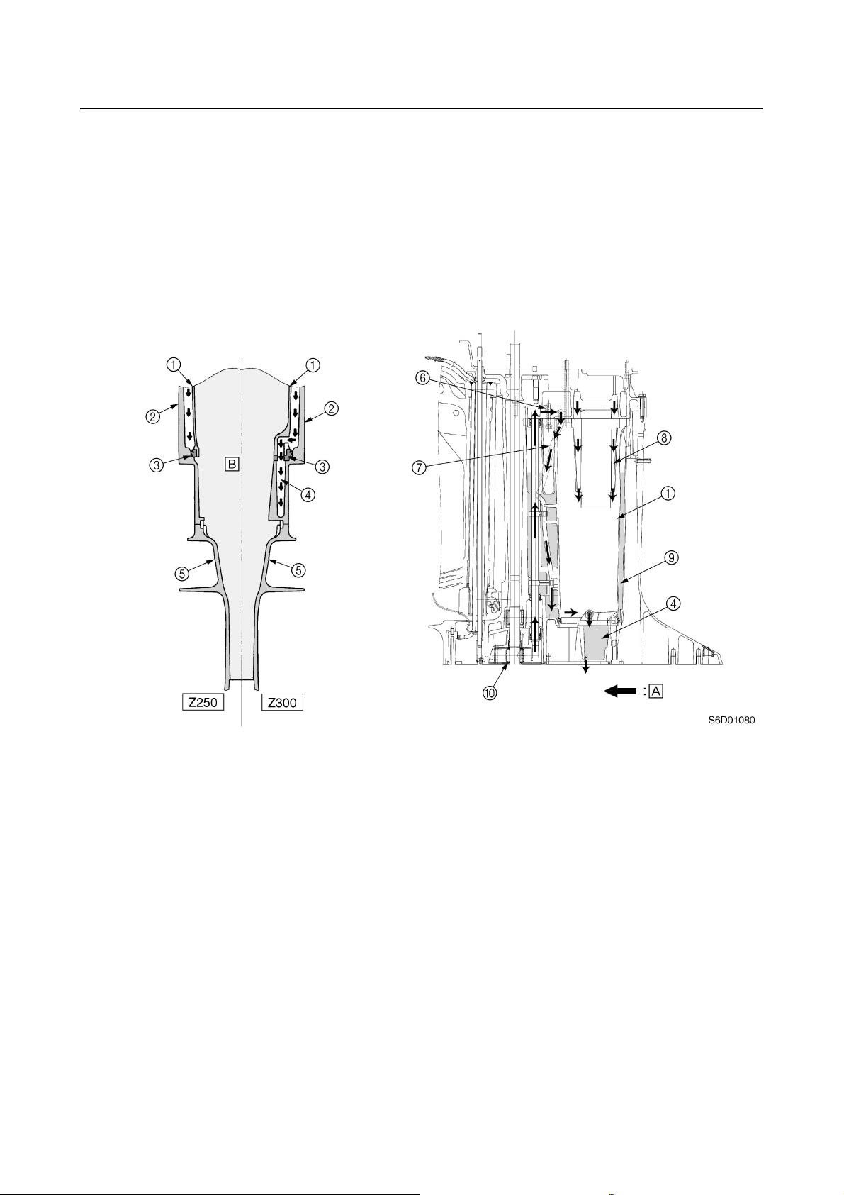
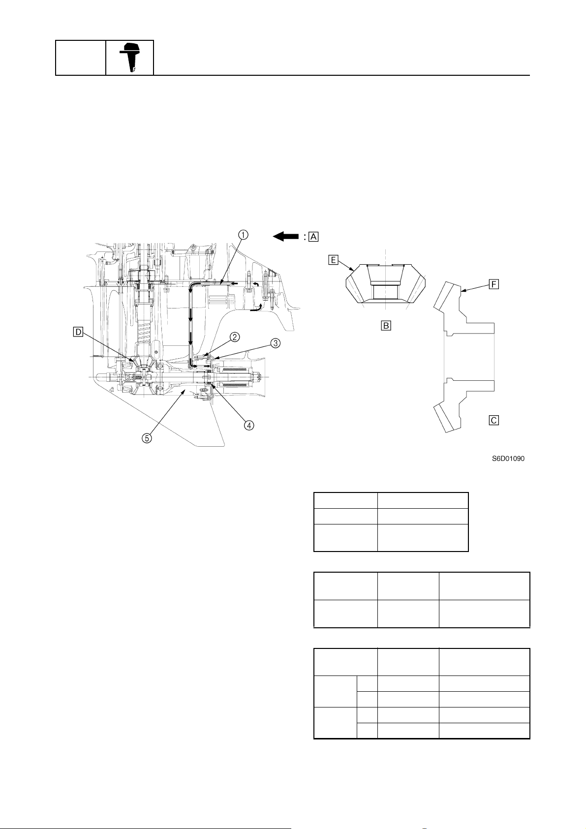
Lower case
The propeller shaft housing and the ring are newly designed to reduce the exhaust back-pressure
and cool the propeller damper.
Cooling water is taken in from the front of the trim tab, flows through the pipe in the lower case and
propeller shaft housing, and then is supplied directly to the propeller boss.
This prevents the cooling water from mixing with the exhaust gas in the exhaust passage in the
lower case and also prevents the cooling water from obstructing the exhaust gas.
Therefore, the exhaust back-pressure can be reduced.
A low gear ratio has been adopted to match the power output characteristics.
General information
Water pipe (for cooling the propeller boss)
1
Heli-sert bushing
2
Ring
3
Fluorine-coated oil seals
4
Propeller shaft housing (with water passage)
5
Water flow
È
Pinion gear
É
Reduction gear
Ê
Ë
Model Gear ratio
Z250 1.81
Z250F
Z300
Ì
Model
Z300
LZ300
Í
Model
Z300
LZ300
1.75
Identification
mark
60X1 Same as Z250F
Identification
mark
F 60X00 Same as Z250F
R 69L00 Same as 250C
F 6D100 New
R 6D100 New
Notes
Notes
9
6D03F1X
Features and benefits
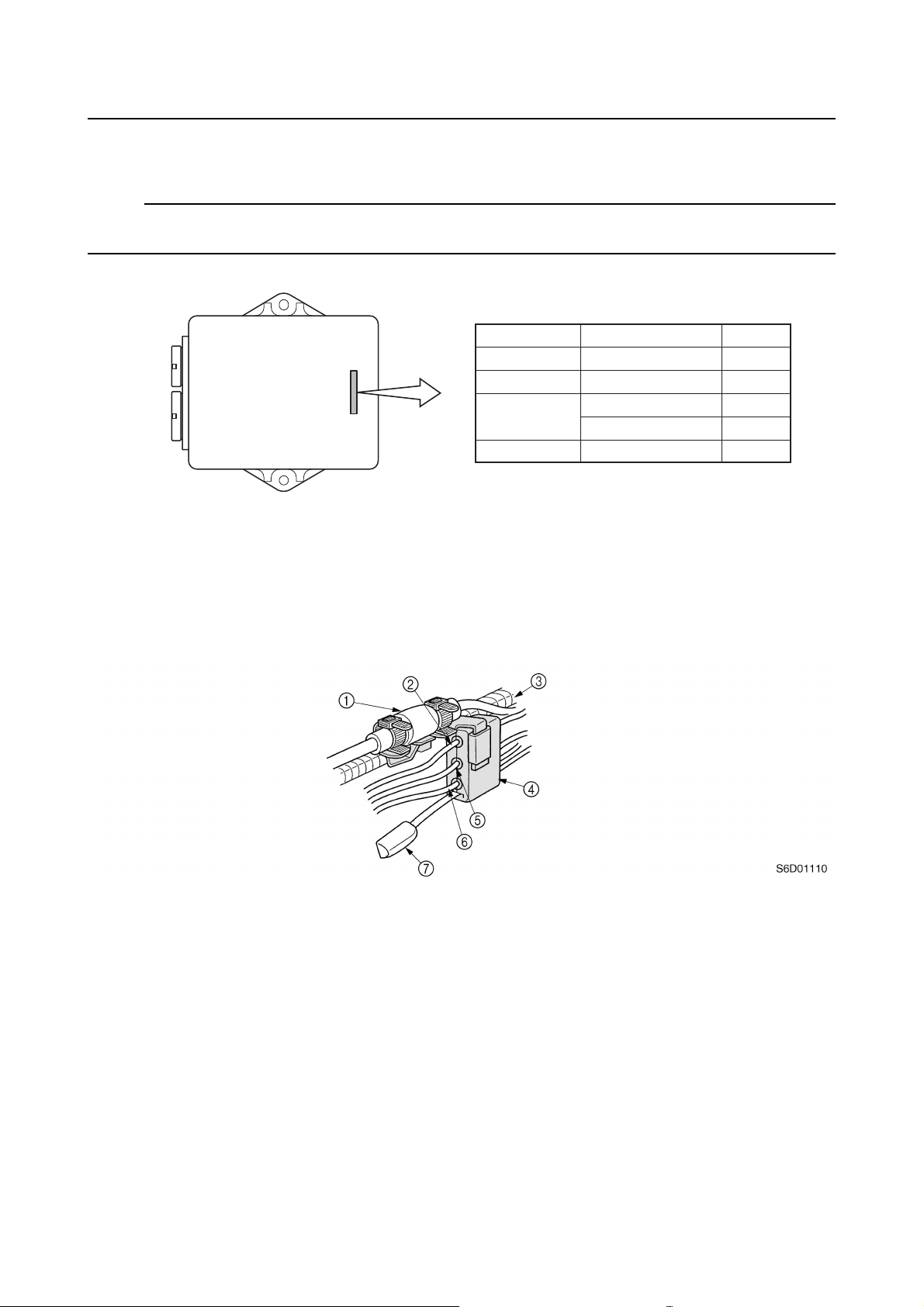
ECM (Electronic Control Module)
ECMs have been adopted that are specific to each model to control the ignition and injection timing.
NOTE:
The diagnostic codes are the same as those for the Z250, and the latest version of the YDIS covers
all previous models with fuel injection.
ÈÉÊ
VZ225 (Z250H) 60Y-01
VZ250 (Z250F) 60X-01
60V-01
60V-21
Ë
S6D01100
Model
È
ECM identification
É
Z250 (Z250D)
Z300 (Z300A) 6D0-00
Note
Ê
For Brazil
Ë
Wiring harness connector holder
A wiring harness connector holder has been added to the side of bottom cowling to secure the 10pin main harness, remote oil tank harness, warning indicator harness, and trim meter harness.
The wiring harness connector holder helps to organize the harnesses and hold them in place.
10-pin main harness
1
Remote oil tank harness (Blue connector)
2
Bottom cowling seal
3
Holder
4
Trim meter harness
5
Warning indicator harness
6
Isolator lead
7
6D03F1X
10
GEN
INFO
General information
Propeller selection
The performance of a boat and outboard
motor will be critically affected by the size
and type of propeller you choose. Propellers
greatly affect boat speed, acceleration,
engine life, fuel economy, and even boating
and steering capabilities. An incorrect choice
could adversely affect performance and
could also seriously damage the engine.
Use the following information as a guide for
selecting a propeller that meets the operating
conditions of the boat and the outboard
motor.
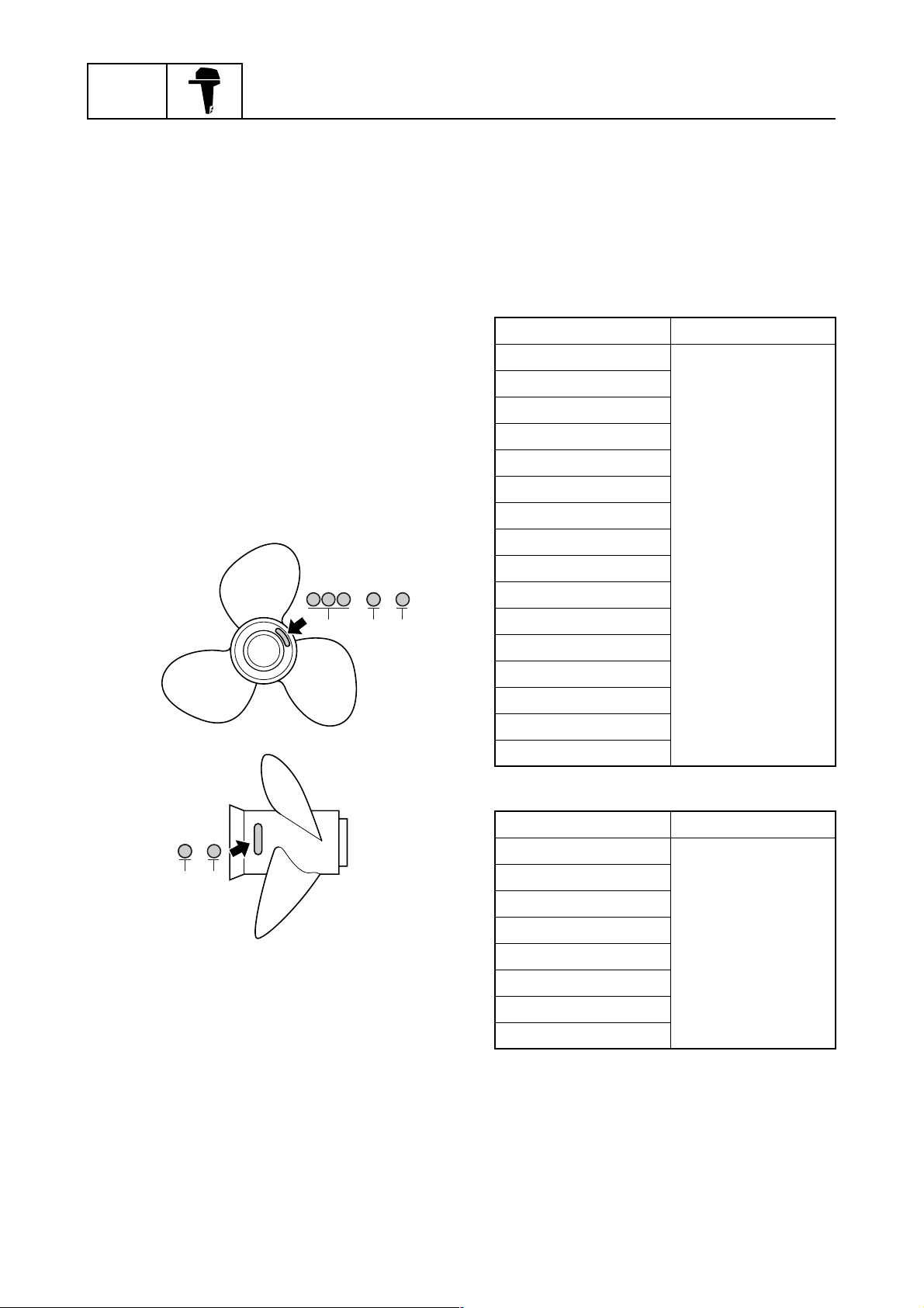
Propeller size
The size of the propeller is indicated on the
propeller boss end and on the side of the propeller boss.
× -
a
bc
S69J1100
1
Selection
When the engine speed is at the full throttle
operating range (4,500–5,500 r/min), the
ideal propeller for the boat is one that provides maximum performance in relation to
boat speed and fuel consumption.
Regular rotation model
Propeller size (in) Material
13 3/8 × 23 - M
13 3/8 × 25 - M
13 3/4 × 17 - M2
13 3/4 × 19 - M2
13 3/4 × 21 - M
14 1/2 × 19 - T
14 1/2 × 21 - T
14 1/2 × 23 - M
Stainless
14 3/4 × 25 - T
14 7/8 × 21 - M
15 × 17 - T
15 1/8 × 27 - T
15 1/4 × 15 - M
15 1/4 × 17 - M
15 1/4 × 19 - M
15 3/4 × 13 - M
-
b
c
Propeller diameter (in inches)
a
Propeller pitch (in inches)
b
Propeller type (propeller mark)
c
S60C1125
Counter rotation model
Propeller size (in) Material
13 3/8 × 23 - ML
13 3/4 × 17 - ML1
13 3/4 × 19 - ML1
13 3/4 × 21 - ML
Stainless
14 1/2 × 19 - TL
14 1/2 × 21 - TL
15 × 17 - TL
15 1/4 × 15 - ML
11
6D03F1X
Propeller selection / Predelivery checks
Predelivery checks
To make the delivery process smooth and
efficient, the predelivery checks should be
completed as explained below.
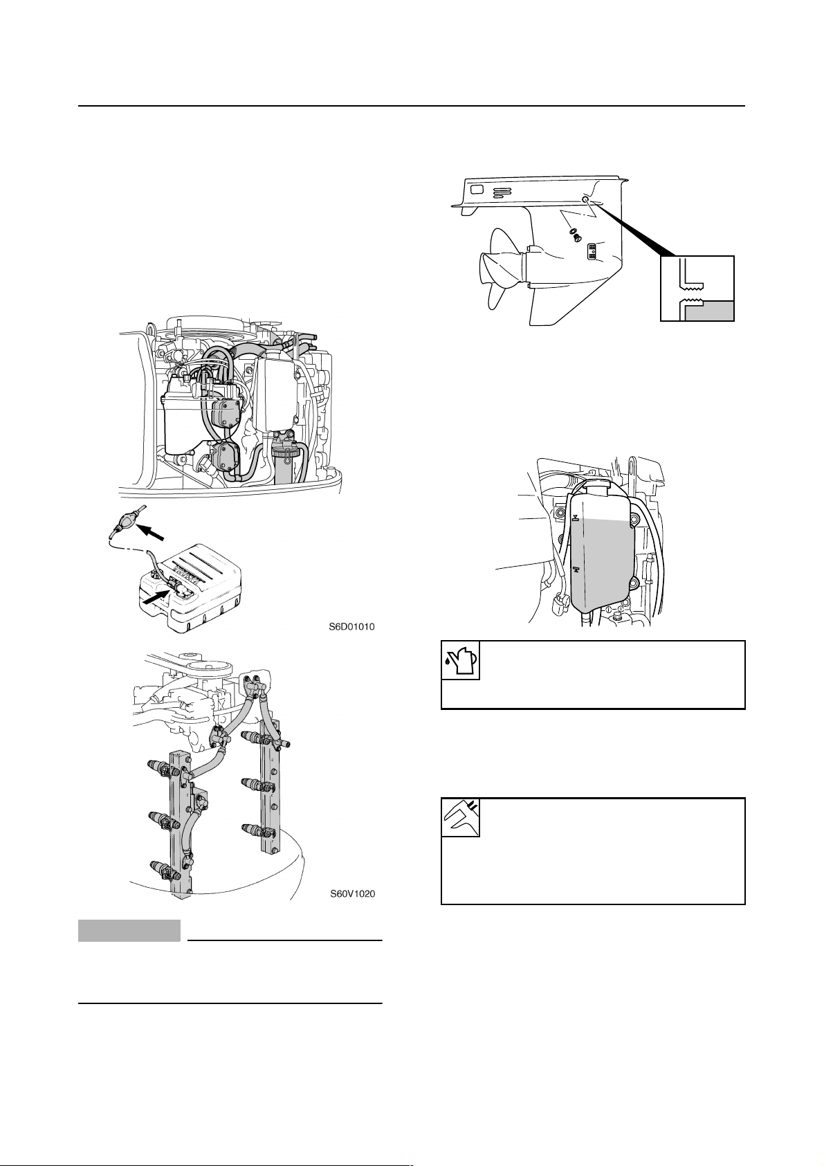
Checking the fuel system
1. Check that the fuel hoses are securely
connected and that the fuel tank is full
with fuel.
1
Checking the gear oil level
1. Check the gear oil level.
S60V1290
Checking the engine oil level
1. Check that the engine oil level is
between the maximum and minimum
level marks.
CAUTION:
• Use unleaded straight gasoline only.
• Do not use gasoline mixed with oil (pre-
mixed fuel).
S60V3260
Recommended engine oil:
YAMALUBE 2-stroke outboard
motor oil
Checking the battery
1. Check the capacity, electrolyte level, and
specified gravity of the battery.
Recommended battery capacity:
CCA/EN: 711 A
20HR/IEC: 100 Ah
Electrolyte specified gravity:
1.280 at 20 °C (68 °F)
2. Check that the positive and negative battery leads are securely connected.
6D03F1X
12
GEN
INFO
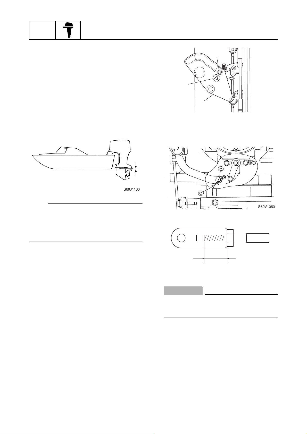
Checking the outboard motor
mounting height
1. Check that the anti-cavitation plate is
aligned with the bottom of the boat. If the
mounting height is too high, cavitation
will occur and propulsion will be reduced.
Also, the engine speed will increase
abnormally and cause the engine to
overheat. If the mounting height is too
low, water resistance will increase and
reduce engine efficiency.
General information
2
a
1
S60V1040
3. Check that the center of the set pin b is
aligned with the alignment mark c on
the bottom cowling.
NOTE:
The optimum mounting height is affected by
the combination of the boat and the outboard
motor. To determine the optimum mounting
height, test run the outboard motor at different heights.
2. Check that the clamp brackets are
secured with the clamp bolts.
Checking the remote control cables
1. Set the remote control lever to the neutral position and fully close the throttle
lever.
2. Check that the throttle cam 1 is in its
fully closed position and align the center
of the throttle cam roller 2 with the alignment mark a.
d
S60C1190
CAUTION:
The shift/throttle cable joint must be
screwed in a minimum of 8.0 mm (0.31 in)
d
.
13
6D03F1X
Predelivery checks
Checking the steering system
1. Check the steering friction for proper
adjustment.
2. Check that the steering operates
smoothly.
S60V1060
3. Check that there is no interference with
wires or hoses when the outboard motor
is steered.
Checking the gear shift and throttle
operation
1. Check that the gear shift operates
smoothly when the remote control lever
is shifted from neutral to forward or
reverse.
Checking the power trim and tilt
system
1. Check that the outboard motor tilts up
and down smoothly when operating the
power trim and tilt unit.
2. Check that there is no abnormal noise
produced when the outboard motor is
tilted up or down.
3. Check that there is no interference with
wires or hoses when the tilted-up outboard motor is steered.
4. Check that the trim meter points down
when the outboard motor is tilted all the
way down.
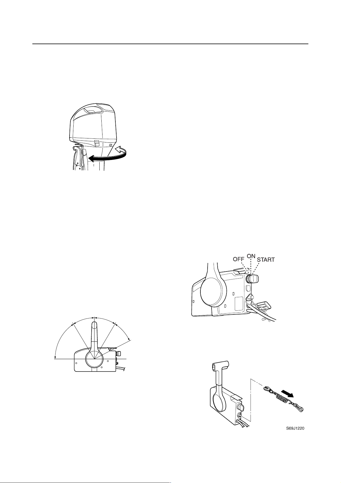
Checking the engine start switch and
engine stop lanyard switch
1. Check that the engine starts when the
engine start switch is turned to START.
2. Check that the engine turns off when the
engine start switch is turned to OFF.
2. Check that the throttle operates smoothly
when the remote control lever is shifted
from the fully closed position to the fully
open position a.
N
F
R
a
a
S69J1210
S60V1070
3. Check that the engine turns off when the
engine stop lanyard is pulled from the
engine stop lanyard switch.
6D03F1X
14

GEN
INFO
Checking the cooling water pilot
hole
1. Check that cooling water is discharged
from the cooling water pilot hole.
General information
cdaÈb
S60V3140
Test run
1. Start the engine, and then check that the
gear shift operates smoothly.
2. Check the engine idle speed after the
engine has been warmed up.
3. Operate at trolling speed.
4. Run the outboard motor for 1 hour at
3,000 r/min or at half throttle, then for
another hour at 4,000 r/min or at 3/4
throttle.
È
Hour
0
1
210
S60V1120
After test run
1. Check for water in the gear oil.
2. Check for fuel leakage in the cowling.
3. Flush the cooling water passage with
fresh water using the flushing kit and with
the engine running at idle.
5. Check that the outboard motor does not
tilt up when shifting into reverse and that
water does not flow in over the transom.
NOTE:
The test run is part of the break-in operation.
Break-in
During the test run, perform the break-in
operation in the following four stages.
1. First 10 minutes a of operation at idle
2. Fifty minutes b at 3,000 r/min or less
3. One hour c at 4,000 r/min or less
4. Eight hours d at 5,000 r/min or less with
repeated wide-open-throttle operation for
5 minutes or less
15
6D03F1X

Predelivery checks / General specifications
General specifications
Item Unit
Dimension
Overall length mm (in) 868 (34.2)
Overall width mm (in) 568 (22.4)
Overall height
(X) mm (in) 1,830 (72.0)
(U) mm (in) 1,957 (77.0) —
Boat transom height
(X) mm (in) 635 (25.0)
(U) mm (in) 762 (30.0) —
Weight
(with stainless propeller)
(X) kg (lb) 252 (556)
(U) kg (lb) 257 (567) —
Performance
Maximum output kW (hp) 220.7 (300) at 5,000 r/min
Full throttle operating range r/min 4,500–5,500
Maximum fuel consumption L (US gal,
lmp gal)/hr
Engine idle speed r/min 700–760
Power unit
Type 2-stroke, 76°, V6, HPDI
Total displacement cm
Bore × stroke mm (in) 93.0 (3.66) × 82.0 (3.23)
Compression ratio 6.2
Control system Remote control
Starting system Electric starter
Enrichment system Fuel injection
Ignition control system TCI
Maximum generator output V, A 12, 50
Spark plug BKR7EKU (NGK)
Cooling system Water
Exhaust system Propeller boss
Lubrication system Oil injection
3
(cu. in) 3,342 (203.9)
Z300AETO LZ300AETO
105.0 (27.7, 23.1) at 5,500 r/min
Model
2
1
2
3
4
5
6
7
8
6D03F1X
9
16

SPEC
Specifications
Item Unit
Z300AETO LZ300AETO
Model
Fuel and oil
Fuel type Regular unleaded gasoline
PON
(*1)
90
86
Fuel minimum rating RON
Engine oil
(*2)
YAMALUBE 2-stroke outboard motor oil
Engine oil tank capacity
Oil tank L (US gal,
1.2 (0.32, 0.26)
lmp gal)
Remote oil tank L (US gal,
10.5 (2.77, 2.31)
lmp gal)
Gear oil type Hypoid gear oil
Gear oil grade SAE 90
Gear oil quantity cm
3
(US oz,
1,150 (38.9, 40.6) 1,000 (33.8, 35.3)
lmp oz)
Bracket unit
Trim angle
Degree –3 to 16
(at 12° boat transom)
Tilt-up angle Degree 70
Steering angle Degree 30 + 30
Drive unit
Gear shift positions F-N-R
Gear ratio 1.75 (28/16)
Reduction gear type Spiral bevel gear
Clutch type Dog clutch
Propeller shaft type Spline
Propeller direction (rear view) Clockwise Counterclockwise
Propeller mark T, M TL, ML
Electrical
Battery minimum capacity
(*3)
CCA/EN A 711
20HR/IEC Ah 100
(*1)
RON: Research Octane Number
PON: Pump Octane Number =
(RON + Motor Octane Number)/2
(*2)
If 2-stroke outboard motor oil is not available, a 2stroke NMMA-certified TC-W3 oil of equivalent
quality must be used.
(*3)
CCA: Cold Cranking Ampere
EN: European Norm (European standard)
IEC: International Electrotechnical Commission
17
6D03F1X
General specifications / Maintenance specifications
Maintenance specifications
Power unit
Item Unit
Z300AETO LZ300AETO
Power unit
Minimum compression
pressure*
kPa
(kgf/cm
2
, psi)
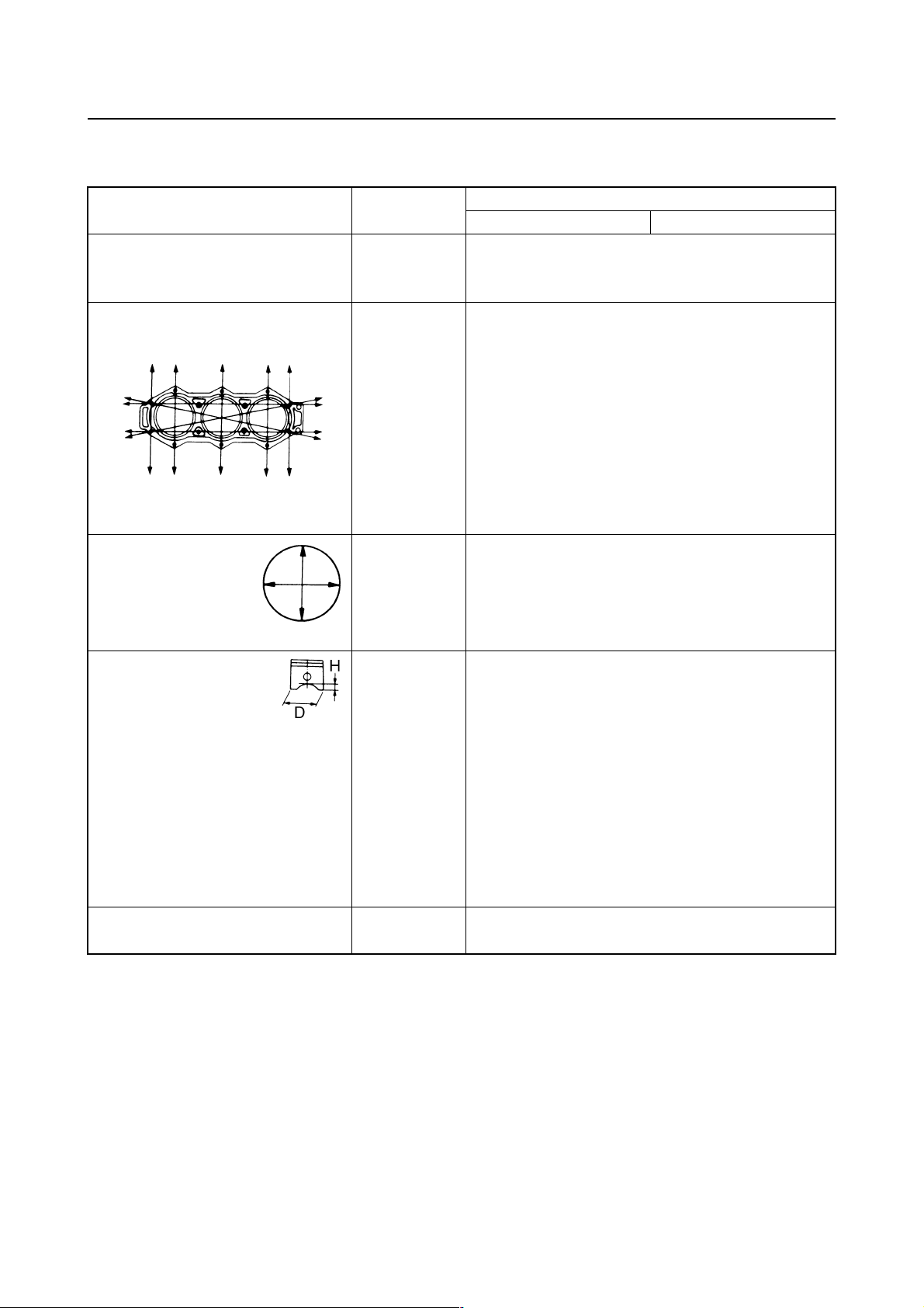
Cylinder heads
Warpage limit mm (in) 0.1 (0.004)
(lines indicate straightedge
position)
Cylinders
Bore size mm (in) 93.000–93.020 (3.6614–3.6622)
Bore size limit mm (in) 93.100 (3.6654)
Taper limit mm (in) 0.08 (0.0031)
Out-of-round limit mm (in) 0.05 (0.0020)
Pistons
Piston diameter (D) mm (in) 92.830–92.850 (3.6547–3.6555)
Measuring point (H) mm (in) 10 (0.39)
Piston-to-cylinder clearance mm (in) 0.165–0.171 (0.0065–0.0067)
Piston pin boss bore mm (in) 26.004–26.015 (1.0238–1.0242)
Oversize piston
1st mm (in) 0.25 (0.010)
2nd mm (in) 0.50 (0.020)
Oversize piston diameter
1st mm (in) 93.080–93.100 (3.6646–3.6653)
2nd mm (in) 93.330–93.350 (3.6744–3.6752)
Piston pins
Outside diameter mm (in) 25.995–26.000 (1.0234–1.0236)
Model
580 (5.8, 84)
2
* Measuring conditions:
Ambient temperature 20 °C (68 °F), wide open throttle, with spark plugs removed from all
cylinders.
The figures are for reference only.
6D03F1X
18
SPEC
Specifications
Item Unit
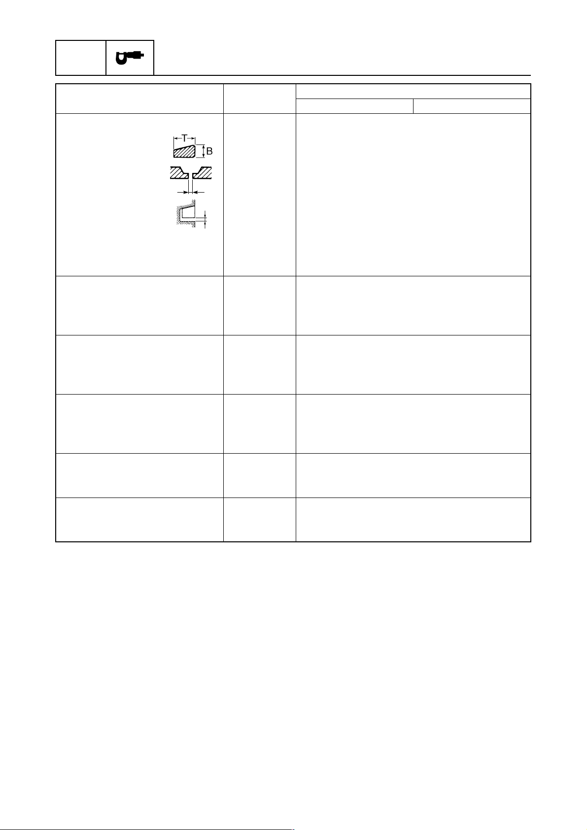
Piston rings
Top ring
Dimension B mm (in) 2.05 (0.0807)
Dimension T mm (in) 3.00–3.20 (0.118–0.126)
End gap mm (in) 0.30–0.50 (0.0118–0.0197)
Side clearance mm (in) 0.02–0.06 (0.0008–0.0024)
2nd piston ring
Dimension B mm (in) 2.05 (0.0807)
Dimension T mm (in) 2.70–2.90 (0.106–0.114)
End gap mm (in) 0.30–0.45 (0.0118–0.0177)
Side clearance mm (in) 0.02–0.06 (0.0008–0.0024)
Connecting rods
Small end inside diameter mm (in) 31.000–31.012 (1.2205–1.2209)
Big end side clearance mm (in) 0.12–0.26 (0.0047–0.0102)
Small end axial play limit mm (in) 2.0 (0.08)
Crankshaft
Crankshaft journal diameter mm (in) 58.975–58.991 (2.3219–2.3225)
Crankpin diameter mm (in) 40.485–40.500 (1.5939–1.5945)
Runout limit mm (in) 0.02 (0.0008)
Thermostats
Opening temperature °C (°F) 48–52 (118–126)
Fully open temperature °C (°F) 60 (140)
Valve open lower limit mm (in) 4.3 (0.17)
Oil pump
Identification mark 6D000
Bleeding Screw type
Reed valves
Valve stopper height limit mm (in) 8 (0.31)
Valve bending limit mm (in) 0.2 (0.008)
Z300AETO LZ300AETO
Model
19
6D03F1X

Lower unit
Maintenance specifications
Item Unit
Gear backlash
Pinion-to-forward gear mm (in) 0.12–0.44
Pinion-to-reverse gear mm (in) 0.61–0.90 (0.0240–0.0354)
Pinion shims mm 0.10, 0.12, 0.15, 0.18, 0.30, 0.40, 0.50
Forward gear shims mm 0.10, 0.12, 0.15, 0.18, 0.30, 0.40, 0.50
Reverse gear shims mm 0.10, 0.12, 0.15, 0.18, 0.30, 0.40, 0.50
Propeller shaft shims mm — 0.10, 0.12, 0.15, 0.18,
Propeller shaft
End play mm (in) — 0.25–0.35
Z300AETO LZ300AETO
(0.0047–0.0173)
Model
0.30–0.62
(0.0118–0.0244)
0.30, 0.40, 0.50
(0.0098–0.0138)
Electrical
Item Unit
Ignition and ignition control
system
Ignition timing (cylinder #1) Degree ATDC 7 at engine idle speed
Degree BTDC 14 at 5,500 r/min
Spark plug gap mm (in) 1.5–1.6 (0.059–0.063)
Ignition coil resistance
Primary coil (R – B/W)
at 20 °C (68 °F)
Secondary coil
(R – spark plug wire)
at 20 °C (68 °F) kΩ 7.31–9.89
ECM output peak voltage
(R – B/W)
at cranking (loaded) V 265
at 1,500 r/min (loaded) V 240
at 3,500 r/min (loaded) V 240
Pulser coil output peak voltage
(W/R, W/B, W/Y, W/G,
W/L, W/Br – B)
at cranking (unloaded) V 3.5
at cranking (loaded) V 3.5
at 1,500 r/min (loaded) V 20.0
at 3,500 r/min (loaded) V 30.0
Ω
1.36–1.84
Z300AETO LZ300AETO
Model
6D03F1X
20
 Loading...