


YAMAHA
4RP-28197-20

EBOOOOOO
LB50 II AC/LBBO II
SERVICE
©1997
by
First
All
rights
reserved.
unauthorized
permission
is expressly
Yamaha
edition,
Any
use
without
of
Yamaha
AC
MANUAL
Motor
March
Co., Ltd.
1997
reproduction
the
Motor
prohibited.
or
written
Co., Ltd.
INDEX
GENERAL
PERIODIC
AND
,
ENGINE
CARBURETION
ADJUSTMENTS
INFORMATION
INSPECTIONS
OVERHAUL
CHASSIS
ELECTRICAL
APPENDICES

CHAPTER
FEATURES ....................................................................................................................... 1
MACHINE IDENTIFICATION ............................................................................................ 5
EXTERNAL
SPECIFICATIONS ............................................................................................................. 8
GENERAL SPECIFICATIONS ................................................................................... 8
MAINTENANCE
GENERAL TORQUE SPECIFICATIONS .........................................................................
CABLE ROUTING ........................................................................................................... 20
SPECIAL TOOLS ............................................................................................................
VIEW
............................................................................................................. 6
SPECIFICATIONS .......................................................................
1.
GENERAL
INFORMATION
11
19
29

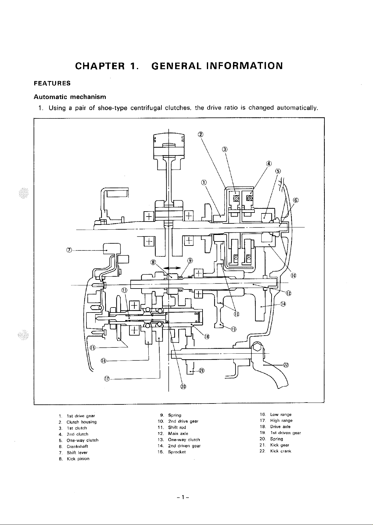
FEATURES
CHAPTER
1.
GENERAL
INFORMATION
Automatic
1.
Using a pair
mechanism
of
shoe-type
centrifugal
clutches.
the
drive ratio is changed automatically.
®
1st
drive gear
1
Clutch housing
2.
1st
clutch
3.
2nd
clutch
4.
One-way
5.
Crankshaft
6
Shift
7.
Kick pinion
8.
lever
clutch
@-------'
©-----~
9. Spring
2nd
Shift
Main
2nd
driven gear
drive gear
rod
axle
10:
11.
12.
13. One-way clutch
14
15. Sprocket
- 1 -
®
low
16.
17. High range
18. Drive axle
19. 1st driven gear
20
21. Kick gear
22
range
Spring
Kick crank
2. The use
operation
the
rider.
according
of
an
automatic
of
the
shift
When
to
starting out,
engine load. This
2-speed
lever.
That
gears
will
centrifugal
is, ease
are
of
automatically
result in a
clutch
relieves
operation
longer
and
additional
shifted
life
of
the
into
the
rider
from
the
cumbersome
safety are ensured for
first, and
then
engine.
into
second
Automatic
The
automatic
1st
gear clutch:
2nd
gear
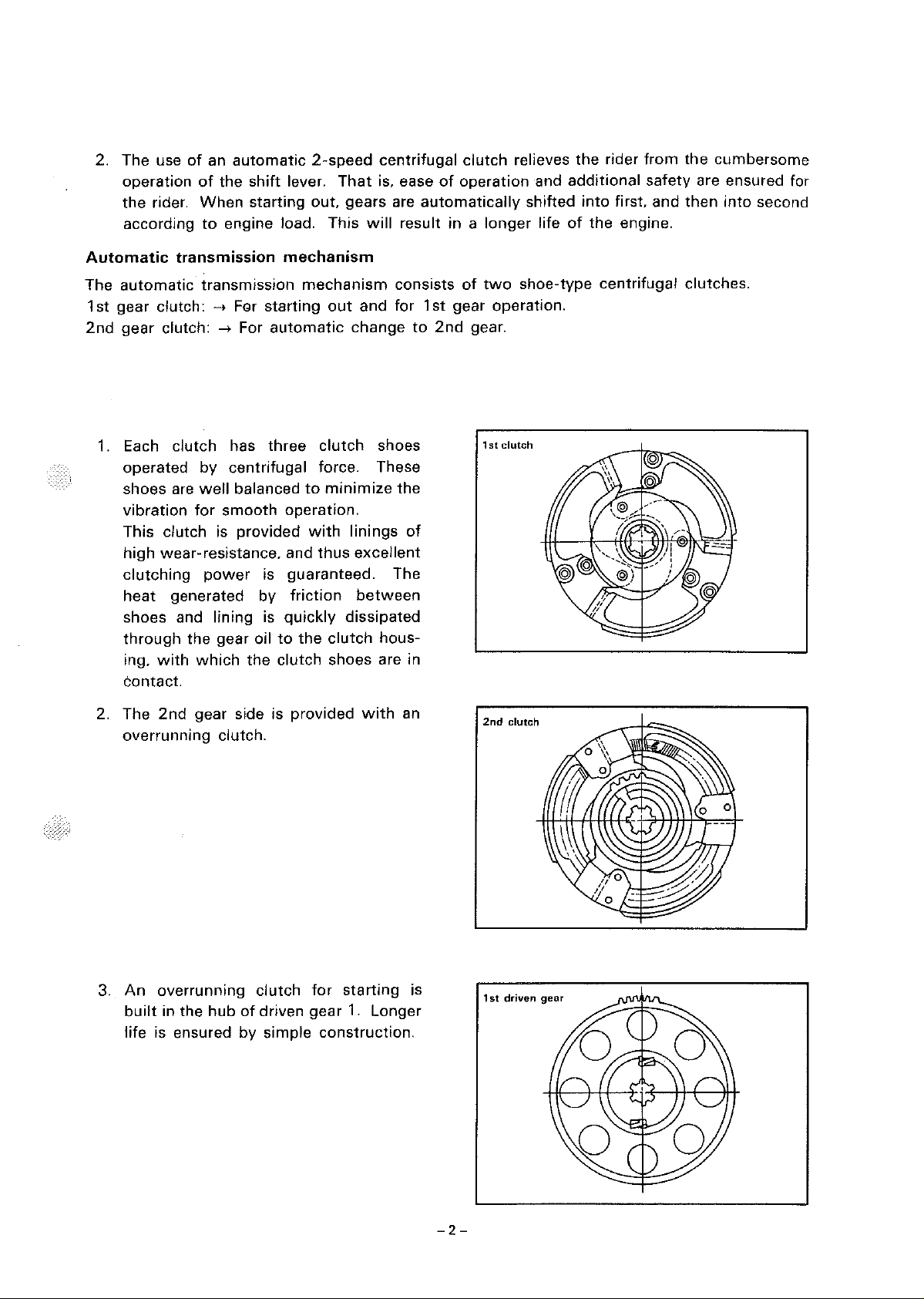
1.
Each
transmission
clutch:
clutch
operated
shoes are
vibration
This clutch is
high
wear-resistance. and
clutching
heat
generated
shoes and lining is
through
ing,
the
with
contact.
transmission
-,
FGr
starting
-,
For
automatic
has
three
by
centrifugal
well
balanced
for
smooth
provided
power
is guaranteed. The
by
gear oil
which
the
mechanism
mechanism
out
change
clutch
force. These
to
minimize
operation.
with
linings
thus
friction
quickly
to
the
clutch
dissipated
clutch
shoes are in
consists
and for
shoes
the
of
excellent
between
hous-
of
1st
gear operation.
to
2nd
gear.
two
shoe-type
1st clutch
centrifugal
clutches.
2. The
2nd
overrunning
3.
An
overrunning
built
in
life is ensured
gear side is
clutch.
the
hub
of
by
provided
clutch
for
driven gear
simple
construction.
with
starting
1.
Longer
an
is
2nd
1st
clutch
driven
gear
-2-
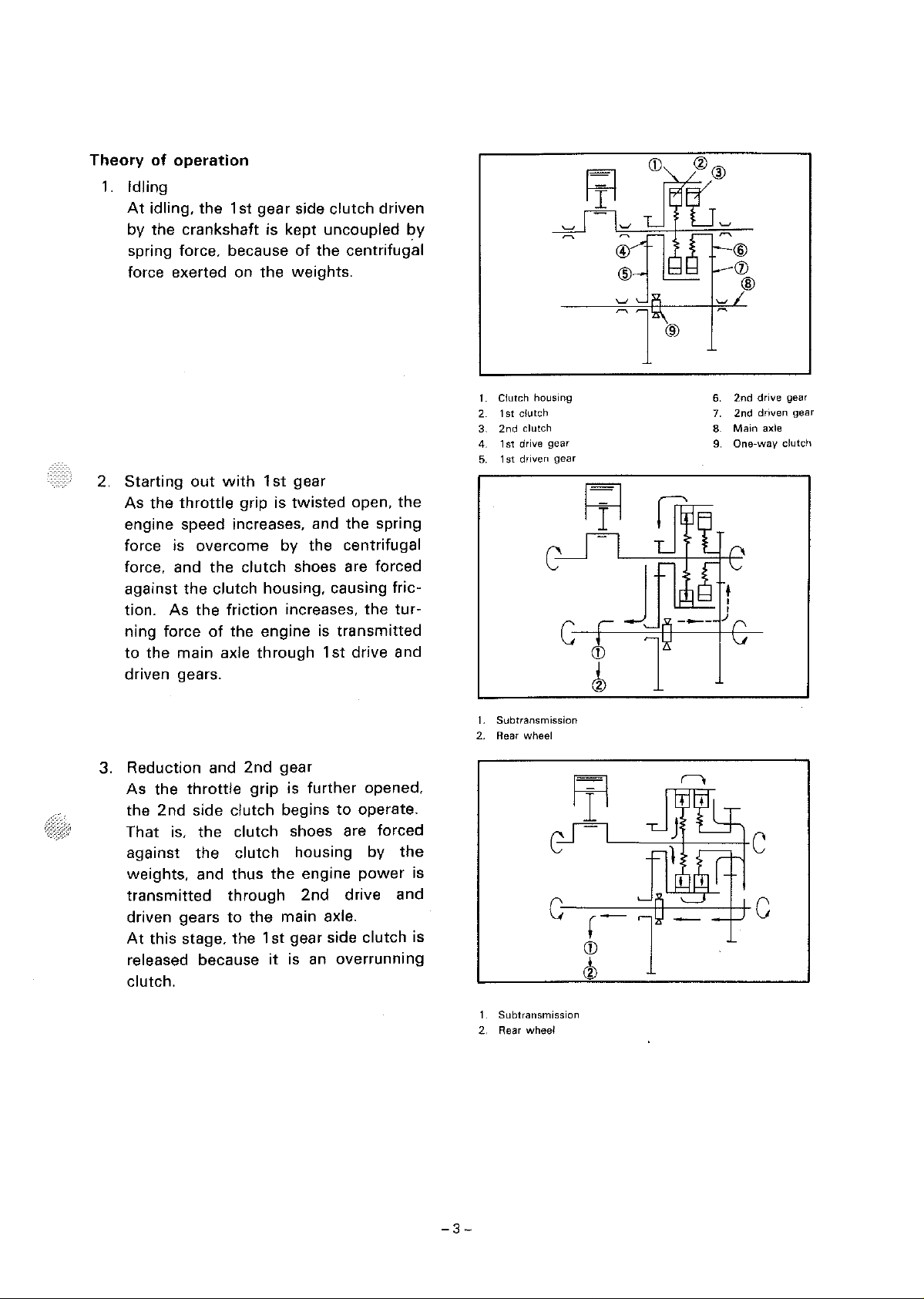
Theory
1.
2.
of
operation
Idling
At
idling, the 1st
gear
by the crankshaft is
spring force, because
with
grip is
the
1st
force exerted on
Starting
As
the
out
throttle
side
clutch
kept
uncoupled
of
the centrifugal
weights.
gear
twisted
engine speed increases, and the spring
force is
overcome
force, and
against
the
tion. As
ning force
to
the main axle
the
clutch housing, causing fric-
the
friction
of
the engine is
by the centrifugal
clutch
shoes are forced
increases,
through
1st
transmitted
driven gears.
driven
by
open,
the
the
tur-
drive and
t.
Clutch housing
1st
dutch
2
3.
2nd
clutch
4.
1st
drive
5.
1st
driven
gear
gear
CD
@
(j)
®
6.
2nd
drive
2nd
driven gear
7.
8. Main axle
9.
One-way
gear
dutch
3. Reduction and
As
the
throttle
2nd
the
That is,
against
side clutch begins
the
the
weights, and thus
transmitted
driven gears
At
this stage, the
to
released because
clutch.
2nd
gear
grip
is
further
opened,
to
operate.
clutch shoes are forced
clutch
through
housing by
the
engine
2nd
the
main axle.
1st
gear side clutch is
it
is an
the
power
drive and
overrunning
is
1.
Subtransmission
2.
Rear wheel
1.
Subtransmission
2. Rear
wheel
G
c-
_---1-1-----=-.l-l-
1
CD
c1
c
-3-
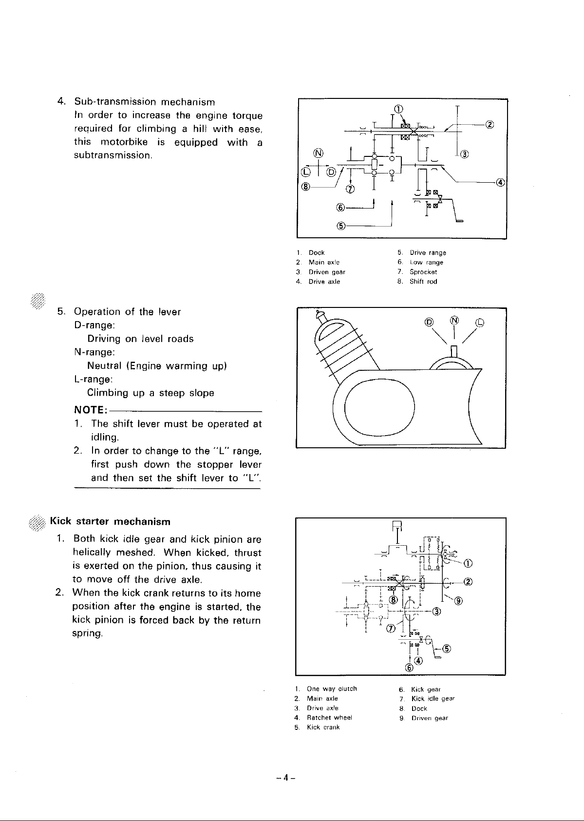
4.
Sub-transmission
In
order
required
this
motorbike
subtransmission.
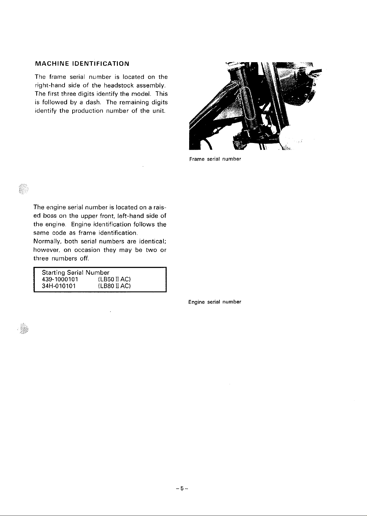
5.
Operation
D-range:
Driving on level roads
N-range:
Neutral (Engine
L-range:
Climbing
mechanism
to
increase the engine
for
climbing
a hill
is equipped
of
the lever
warming
up
a steep slope
with
up)
torque
ease,
with
a
1
Dock
2
Main
Driven
axle
gear
3
4. Drive axle
5 Drive range
6 Low range
7
Sprocket
8. Shift rod
@ ® ©
~I/
NOTE:-----------
1.
The
shift
lever
idling.
order
2. In
to
first push
then
and
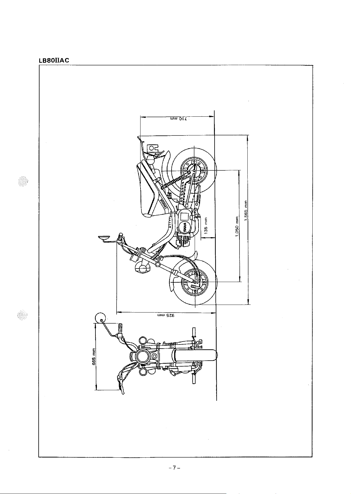
Kick
starter
1.
Both kick idle gear and
mechanism
helically meshed.
is exerted on the pinion,
to
2.
move
When
position
kick
off
the drive axle.
the
kick crank returns
after
pinion
is forced back by
spring.
must
be operated at
change
down
set the
to
the
shift
When
the
"L"
stopper
lever
kick
pinion are
kicked,
thus
to
range,
lever
to
"L".
thrust
causing
its
home
the engine is started, the
the
return
it
1 One
way
2
Main
Drive
Ratchet
axle
axle
3
4
5 Kick crank
clutch
wheel
6 Kick
gear
7 Kick idle gear
8
Dock
9
Driven
gear
-4-
MACHINE
The
frame
right-hand
The
first
is
followed
identify
the
IDENTIFICATION
serial
side
three
by
number
of
the
digits
identify
a dash. The
production
is
located
headstock
the
remaining
number
on
assembly.
model.
digits
of
the
unit.
the
This
Frame serial number
The engine serial
ed boss
the
same
Normally,
however,
three
on
engine. Engine
code
both
on
numbers
Starting
the
upper
as
frame
serial
occasion
off.
Serial
number
is
front,
identification
identification.
numbers
they
Number
439-1000101 (LB50 II AC)
34H-010101 (LB80 II AC)
located
left-hand
follows
are
may
be
on a rais-
side
of
the
identical;
two
or
Engine serial number
-5-

EXTERNAL VIEW
LB50
II
AC
1------ww
oiL--~-i
~
~
o_
E
E
0
~
E
"\
E
-6-
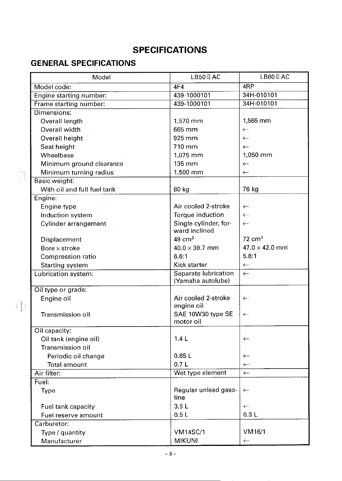
LB80IIAC
WW
QLL
E
E
0
q
E
E
"'
"'
"'
-7-
SPECIFICATIONS
GENERAL SPECIFICATIONS
Model
Engine
Frame
code: 4F4
starting
starting
Dimensions:
Overall length
Overall
Overall
Seat
width
height
height
Wheelbase
Minimum
Minimum
Basic
weight:
With
oil
ground
turning
and
Engine:
Engine
Induction
Cylinder
type
system
arrangement
Displacement
Bore x stroke
Compression
Starting
Lubrication
Oil type
Engine
system
system:
or
grade:
oil
Transmission
Oil capacity:
Oil
tank
(engine oil)
Transmission
Periodic oil change
Total
amount
Air
filter:
Fuel:
Type
Fuel
tank
capacity
Fuel reserve
Carburetor:
Type
I
quantity
Manufacturer
Model
number:
number:
clearance
radius
full
fuel tank
ratio
oil
oil
amount
LB50 II
AC
439-1000101
439-1000101
1,570
mm
665
mm
925mm
710
mm
1,075
135
1,500
mm
mm
mm
80 kg
Air
cooled
Torque
Single cylinder,
ward
49
cm
40.0 x 39.7
2-stroke
induction
for-
inclined
3
mm
6.6:1
Kick starter
Separate lubrication
(Yamaha autolube)
Air
cooled
engine
SAE 10W30 type
motor
2-stroke
oil
SE
oil
1.4 L
0.65 L
0.7 L
Wet
type
element
Regular unlead gasoline
3.5 L
0.5 L
VM14SC/1
MIKUNI
LB80 II
AC
4RP
34H-010101
34H-010101
1,565
mm
fff-
1,050
ff-
76
fff-
72
kg
cm
mm
3
47.0 x 42.0 mrn
5.8:1
ff-
f-
f-
f-
fff-
f-
f-
0.3 L
VM16/1
f-
-8-

Model
Spark plug:
Type
Manufacturer
Spark
plug
gap
B6HS
NGK
0.5 - 0.6
Clutch type: Wet,
matic
Transmission:
Secondary reduction system Chain
Secondary
Transmission
reduction
type
ratio 31/14 (2.214) 30/15 (2.000)
Constant mesh 2speed
Operation
Centrifugal
type
Gear ratio 1st
2nd
Sub-transmission
Sub-transmission
ratio
ratio
low
high
69/18 (3.833)
59/28 (2.107)
39/12 (3.250)
35/16 (2.188)
Chassis:
Frame type
Caster angle
Trail
Steel tube
26'
45mm
Tire:
Type
Size
Manufacturer
front
rear
front
With
4.00-8-4PR
4.00-8-4PR
INOUE
rear INOUE
Tire pressure (cold tire):
Loading
condition
A * 0 - 70
front
100
1.00 bar)
rear 125
1.25 bar)
Loading
condition
B *
front
70
100
1.00 bar)
rear
200
2.00 bar)
Brake:
Front
Rear brake
* Load
brake
1s
the
total
weight
type
operation
type
operation
of
cargo, rider, passenger and accessories.
Drum
Right hand
Drum
Left hand
LB50 II
mm
centrifugal
drive
automatic
underbone
tube
kg
kPa
(1.00
kPa
( 1.25
-140
kg
kPa
( 1.00
kPa
(2.00
brake
brake
operation
AC
auto-
automatic
kg/cm',
kg/cm',
kg/cm',
kg/cm',
operation
LB80 II
ffff-
f-
f-
f-
fff-
29/15 ( 1.933)
fff-
fffff-
0 - 74
f-
f-
kg
74-144kg
f-
150
kPa
( 150
1.50 bar)
ffff-
AC
kg/cm',
-9-
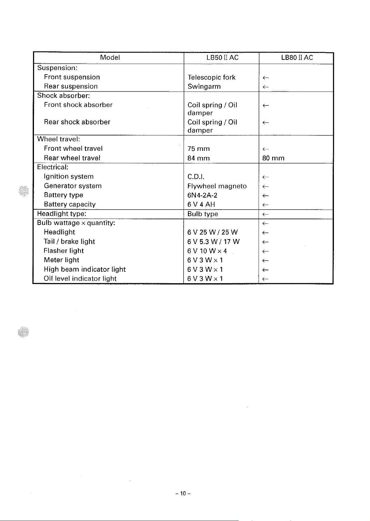
Suspension:
Front
Rear suspension
Shock absorber:
Front
Rear shock absorber
Wheel travel:
Front
Rear
Electrical:
Ignition
Generator system
Battery
Battery capacity
Headlight
Bulb
Headlight
Tail I brake
Flasher
Meter
High beam
Oil level
suspension
shock absorber
wheel travel
wheel
wattage
travel
system
type
type:
x quantity:
light
light
light
indicator
indicator
Model
light
light
LB50 II
Telescopic
Swingarm
Coil spring
damper
Coil spring
damper
75
mm
84mm
C.D.I.
Flywheel
6N4-2A-2
6 V 4 AH
Bulb
type
6 V
25 W /25
6 V 5.3
6V10Wx4
6V3Wx1
6V3Wx1
6V3Wx1
WI
AC
fork
I Oil
I Oil
magneto
W
17
w
,---,----
,----
,----
,----
80
,---,----
,----
,----
,---,---,---,---,---,---,---,----
mm
LB80 II
AC
- 10 -
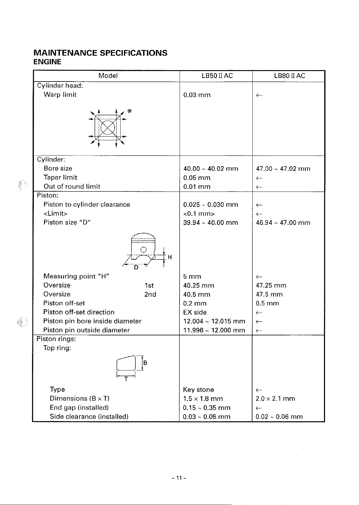
MAINTENANCE
ENGINE
SPECIFICATIONS
Cylinder
Warp
Cylinder:
Bore size
Taper
Out
of
Piston:
Piston
<Limit>
Piston size
head:
limit
limit
round
to
cylinder
limit
"D"
Model
,-*
clearance
LB50 II
0.03
mm
40.00 - 40.02
0.05
mm
0.01
mm
0.025 - 0.030
<0.1
mm>
39.94 - 40.00
AC
mm
mm
mm
LBBO
IIAC
47.00 - 47.02
ff-
46.94 -
47
.00
mm
mm
Measuring
Oversize
Oversize
Piston
Piston
Piston
Piston
Piston rings:
Top ring:
Type
Dimensions
End
Side clearance (installed)
point
off-set
off-set
pin
bore
pin
outside
gap
(installed)
"H"
direction
inside
(Bx
diameter
diameter
CJ]s
I T I
T)
1st
2nd
5mm
40.25
40.5
0.2
EX side
12.004 - 12.015
11.996 - 12.000
Key stone
1.5 x 1.8
0.15 - 0.35
0.03 - 0.05
mm
mm
mm
mm
mm
mm
mm
mm
f-
47.25
47.5
0.5
fff-
f-
2.0 x
f-
0.02 - 0.06
mm
mm
mm
2.1
mm
mm
-
11
-

2nd ring:
Type
Dimensions
End gap (installed)
Side clearance
2nd ring:
(8 x T)
Model LB50 II
C]Js
I
T
I
Keystone
1.5
x 1.8
mm
0.15-
0.03 - 0.05
0.35
mm
mm
AC
LB80 II
-
-
-
-
AC
T
F
l]s
I
-
-
-
- 0.02 - 0.06
Plain
2.0 x 2.1
0.15 - 0.35
mm
mm
mm
Type
Dimensions
End gap (installed)
Side clearance
Crankshaft:
I
I
(8 x T)
-
4~
E}D
A
Crank
Runout
Big
Big
Small end free play
Automatic
Clutch shoe thickness
<Wear
Clutch-stall revolution 2,800 - 3,200 r/min 2,700 - 3,200 r/min
Transmission:
Main
Drive axle deflection
Kick starter:
Kick starter
Kick
width
end
end
axle deflection
clip
"A"
limit
"C"
side clearance
radial clearance
centrifugal clutch:
limit>
type
friction
"F"
force
"D"
limit
limit
"E"
37.90 - 37.95
0.015
0.20 - 0.50
0.004 - 0.015
0.8 - 2.0
2.5mm
<2
0.015
0.015
Kick and mesh
8.0 - 20.0 N 8.0 (0.8 - 2.0 kg) (0.8 -
mm
mm>
mm
mm
mm
mm
mm
mm
type
fff-
0.004 - 0.017
f-
ff-
ff-
Ratchet type
15.0
1.5
N
kg)
mm
-
12
-
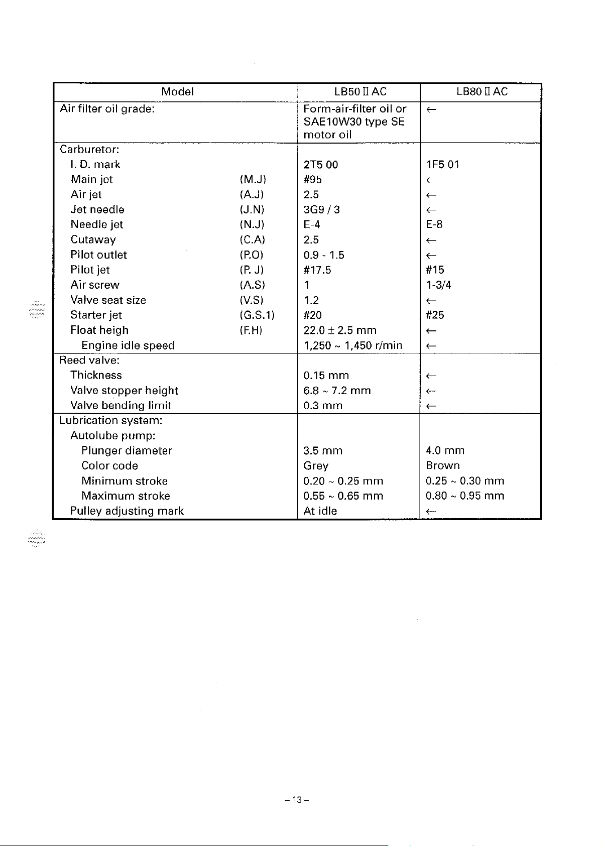
Model
Air
filter
oil grade:
Carburetor:
I.
D.
mark
Main
jet
Air
jet
Jet
needle
Needle
Cutaway
Pilot
Pilot
Air
Valve seat size
Starter
Float heigh
Reed valve:
Thickness
Valve
Valve
Lubrication system:
Autolube
Pulley
jet
outlet
jet
screw
jet
Engine
Plunger
Color code Grey
Minimum
Maximum
idle
stopper
bending
pump:
diameter
stroke 0.20 - 0.25
stroke
adjusting
speed
height
limit
mark
(M.J)
(A.J)
(J.N)
(N.J)
(C.A)
(P.0)
(P.
J)
(AS)
(V.S)
(G.S.1)
(F.H)
LB50 II AC
Form-air-filter
SAE10W30
motor
2T5
#95
2.5
3G9/3
E-4
2.5
0.9 - 1.5
#17.5
1
1.2
#20
22.0±
1,250 - 1,450 r/min
0.15
6.8 - 7.2
0.3
3.5mm
0.55 - 0.65
At
oil
00
2.5
mm
mm
idle
mm
mm
mm
mm
oil
type
SE
or
LB80 II
s--
1F5
01
s-s-s--
E-8
s-s--
#15
1-3/4
s--
#25
s-s--
s-s-s--
4.0
mm
Brown
0.25 - 0.30
0.80 - 0.95
s--
AC
mm
mm
-
13
-

CHASSIS
Steering system:
Steering bearing
No. I size
of
steel balls
Front suspension:
Front
Fork
Spring
fork
spring
rate
travel
free length
Stroke
Optional
spring
Oil capacity
Oil grade
Rear suspension:
Shock
Spring
Fitting
Spring
absorber
free
length
length
rate
Stroke
Optional
spring
Swingarm:
Free play
Front
wheel:
limit
Type
Rim size
Rim
material
Rim
runout
limit
Rear wheel:
Type
Rim size
Rim
material
Rim
runout
limit
Model
type
travel
LB50
Ball bearing
upper
lower
(K1)
(K2)
(K1)
(K2)
22
pcs I
19
pcs I 0.25 in
75
mm
482
mm
8.45
N/mm
(0.845
18.0
O -
kg/mm)
N/mm
48
mm
48-75
0.
mm
No
left
right
96
120
cm
cm
3
3
Fork oil 10W
valent
65
mm
212
mm
207
mm
(K1) 21.0 N/mm
(K2)
(K1)
(K2)
N/mm
28.5
(2.85
kg/mm)
O -
34
34 -65
mm
mm
No
end 1
side
mm
0.5
Disc
mm
wheel
2.50C x 8
Steel
radial
lateral
1mm
1mm
Disc
wheel
2.50C x 8
Steel
radial
lateral
1mm
1mm
II
AC
1875 in
(1.8
kg/mm) r
or
equi- r
(2.1
kg/mm) r
LB80 II
r
r
r
r
r
r
r
r
r
r
r
r
r
r
r
r
r
r
r
r
r
r
r
r
r
r
r
r
r
r
AC
-
14-
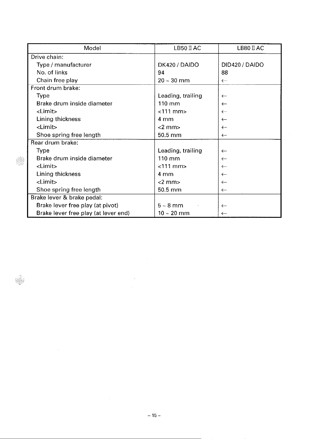
Model
Drive chain:
Type
I
No.
Chain
Front
manufacturer
of
links 94 88
free
play
drum
brake:
DK420 I DAIDO DID420 I DAIDO
20 -
Type Leading,
Brake
<Limit>
Lining thickness
<Limit>
Shoe
Rear
Type
Brake
<Limit>
Lining thickness
<Limit>
Shoe
Brake
Brake
Brake
drum
spring
drum
drum
spring
lever
lever
lever
inside
diameter
free length
brake:
inside
diameter
free length 50.5
& brake pedal:
free play (at pivot)
free play (at lever end)
110
<111
4mm
<2
mm>
50.5
Leading,
110
<111
4mm
<2
mm>
5-8mm
10-20mm
LB50 II
30
mm
mm>
mm
mm
mm>
mm
mm
trailing
trailing
AC
<c-
<c<c<c<c<c<c-
<c<c<c<c<c<c-
<c<c-
LB80 II
AC
-15-
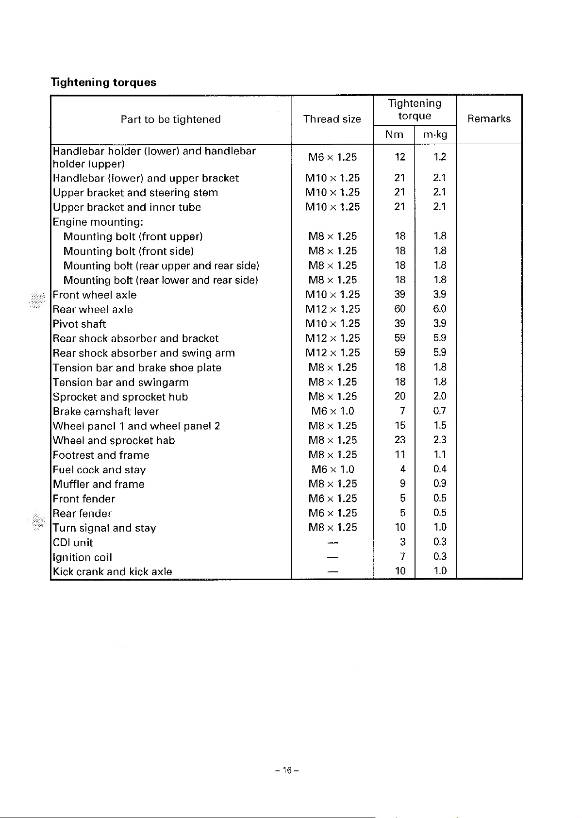
lightening
Handlebar
holder
Handlebar
Upper
Upper
Engine
Mounting
Mounting
Mounting bolt (rear upper and rear side)
Mounting bolt (rear
Front
Rear
Pivot
Rear shock
Rear shock
Tension
Tension
Sprocket and
Brake
Wheel panel 1
Wheel
Footrest and
Fuel cock
Muffler
Front
Rear
Turn
CDI
Ignition
Kick crank and kick axle
wheel
wheel
shaft
fender
fender
signal and
unit
torques
Part
holder
(upper)
(lower)
bracket
bracket
mounting:
bolt
bolt
axle
axle
absorber
absorber
bar
and brake shoe plate
bar
and
sprocket
camshaft
and
sprocket hab
frame
and
stay
and
frame
coil
to
be
(lower) and
and
and
steering stem
and
inner
(front
(front
lower
and bracket
and
swingarm
lever
and
wheel
stay
tightened
handlebar
upper
upper)
side)
hub
bracket
tube
and rear side)
swing
panel 2
arm
Thread size
M6
x 1.25
M10 x 1.25
M10 x 1.25
M10 x 1.25
MS
x 1.25
MS
x 1.25
MS
x 1.25
MS
x 1.25
M10 x 1.25
M12 x 1.25
M10 x 1.25
M12 x 1.25
M12 x 1.25
MS
x 1.25
MS
x 1.25
MS
x 1.25
M6
x 1.0 7
MS
x 1.25
MS
x 1.25
MS
x 1.25
M6
x 1.0
MS
x 1.25 9
M6
x 1.25 5
M6
x 1.25 5
MS
x 1.25
-
-
-
Tightening
torque
Nm
m-kg
12
21
21
21
18
18
18
18
39
60
39
59
59
18
18
20
15
23
11
4
10
3
7
10
Remarks
1.2
2.1
2.1
2.1
1.8
1.8
1.8
1.8
3.9
6.0
3.9
5.9
5.9
1.8
1.8
2.0
0.7
1.5
2.3
1.1
0.4
0.9
0.5
0.5
1.0
0.3
0.3
1.0
-
16
-
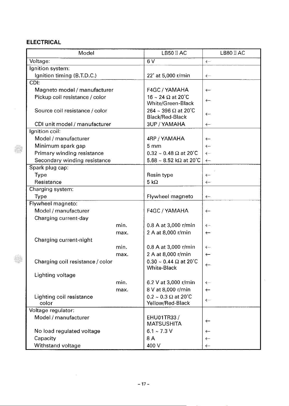
ELECTRICAL
Model
Voltage:
Ignition
Ignition
system:
timing
(B.T.D.C.)
CDI:
Magneto
Pickup coil resistance I
Source coi I
CDI
Ignition
model I manufacturer
resistance/
unit
model I manufacturer
coil:
color
color
Model I manufacturer
Minimum
Primary
Secondary
Spark
plug
spark
winding
winding
cap:
gap
resistance 0.32 - 0.48 Q
resistance 5.68 - 8.52
Type
Resistance 5
Charging system:
Type
Flywheel
magneto:
Model I manufacturer
Charging
current-day
min.
max. 2 A at 8,000
Charging
current-night
min.
max.
Charging coil resistance I
Lighting
voltage
color
min.
max.
Lighting
coil resistance
color
Voltage regulator:
Model I manufacturer
No
load regulated
voltage
Capacity
Withstand
voltage
LB50 II AC LB80 II
6V
22"
at
5,000
r/min
F4GC I YAMAHA
16 -24
Q at 20"C
White/Green-Black
264 - 396 Q
at
20"C
Black/Red-Black
3UP
/YAMAHA
4RP
/YAMAHA
5mm
at
20°C
kQ
at
20°C
Resin
type
kQ
Flywheel
magneto
F4GC I YAMAHA
0.8 A
at
3,000 r/min
r/min
0.8 A
at
3,000 r/min
2 A at 8,000
0.30 - 0.44 Q
r/min
at
20"C
White-Black
6.2
Vat
8
Vat
0.2
- 0.3 Q at
3,000
8,000
r/min
r/min
20°C
Yellow/Red-Black
EHU01TR33 /
MATSUSHITA
6.1
- 7.3 V
8A
400 V
AC
f-
f-
f-
f-
f-
f-
ffff-
ff-
f-
f-
ff-
ff-
f-
ff-
f-
f-
fff-
-17-

Model
Horn:
Type
Quantity
Model I manufacturer
Maximum
amperage
Plane
1
GF-6/
1.5 A
Flasher relay:
Type Condenser
Model I manufacturer
Self cancelling device
Flasher
frequency
Wattage
FR-2212 I
No
60
- 120
10
Wx2
Oil level switch:
Model I manufacturer
2T5 I STANLEY
Circuit breaker:
Type
Amperage
Main
Reserve
for
individual
circuits
Fuse
10
Ax
10
Ax
L850 II
type
NIKKO
type
MITSUBA
cycle/min
1
1
AC
L880 II
(-
(-
(-
(-
(-
(-
(-
(-
(-
(-
(-
(-
(-
AC
-18-
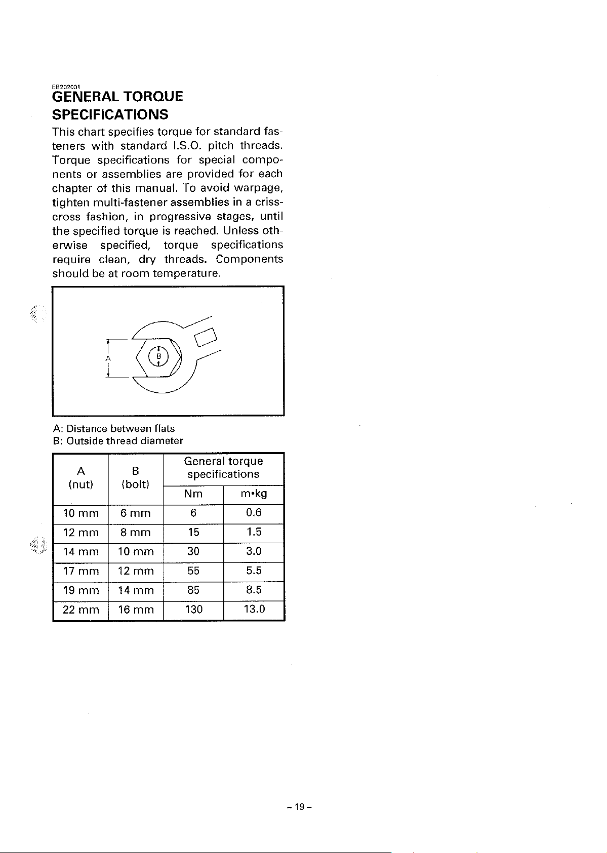
EB202001
GENERAL TORQUE
SPECIFICATIONS
This
chart specifies
teners
Torque
nents
chapter
tighten
with
standard I.S.O. pitch threads.
specifications
or
assemblies are provided
of
this
multi-fastener
cross fashion, in progressive stages,
the
specified
erwise
torque
specified,
require clean,
should
be at
room
torque
manual. To
for
for
standard fas-
special
avoid
assemblies in a criss-
is reached. Unless oth-
dry
torque
threads.
specifications
Components
temperature.
compo-
for
warpage,
each
until
A: Distance between flats
B:
Outside
A
thread
8
diameter
(nut) (bolt)
10
12
14
17
19
22
mm
mm
mm
mm
mm
mm
6mm
8mm
10mm
12
mm
14
mm
16mm
General
torque
specifications
Nm
6
15
30
55
85
130
m•kg
0.6
1.5
3.0
5.5
8.5
13.0
-19-

EB206000
CABLE ROUTING
CD
Speedometer
® Rear brake cable
G)
Starter cable
@ Rear brake switch lead
® Left
@ Front brake cable
(!) Right
®
®
handlebar
handlebar
Front
brake switch lead
Throttle
cable
cable
switch
switch
#1
2
lead
@)
Horn
switch
@
Wire
harness
@ Rectifier/regulator
@)
Rectifier/regulator lead
@Cross
@)
5
bar
Horn
lead
B
A-.......
13
15
c
A
10
[El
14
B
-
20-
16]
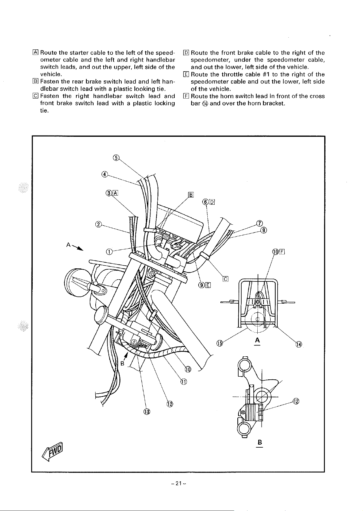
Route
the
starter
ometer
switch leads, and
vehicle.
ill] Fasten
dlebar
19
Fasten
front
tie.
cable and
the
switch lead
the
brake
rear
right
switch
cable
the
out
the
brake
switch
with
handlebar
lead
4
2
to
the
left
and
upper,
a plastic
with
5
left
of
the
speed-
right
handlebar
left
side
of
the
lead and left han-
looking
switch
a plastic locking
tie.
lead and
[l5]
Route the
speedometer,
out
and
the
III Route the
speedometer
of
the
vehicle.
III Route
bar@
B
the
and
front
brake cable
under
lower,
throttle
cable and
horn
switch lead in
over
the
the
left
side
cable
horn
to
the
right
speedometer cable,
of
the
vehicle.
#1
to
the
right
of
out
the
lower, left side
front
of
the
bracket.
of
the
the
cross
A-...,..,,
15
c
A
1 III
14
B
-
21
-

G)
Autolube
®
Throttle
@
Throttle
@
Throttle
®
Right
@
Front
(j)
Front
@ Rectifier/regulator
pump
cable
cable
#1
cable
junction
cable
#2
handlebar
brake switch lead
brake cable
switch lead
® Rectifier/regulator lead
@)
Wire
harness
3
box
@
Speedometer
@ Rear brake cable
@)
Left
handlebar
@)
Rear brake
@)
Starter cable
12\J
Fasten
ITll
19
Faster
cable.
Pass
ness
the
the
through
the
cable
switch
switch
wire
rectifier/regulator
the
front
lead
lead
cylinder.
lead and
cable guide.
brake cable and
wire
har-
speedometer
2
14
4
6
-22-
c

(j)
Front brake cable
®
Throttle
@
Autolube
© Spark
cable
plug
#1
pump
lead
® Rear brake cable
®
Autolube
(J)
Oil feed hose
®
Wire
®
CDI
@)
Fuel cock
pump
harness
magneto
vacuum
lead
® Fuel hose
cable
hose
@I
Band
@
Mixing
chamber
air
vent
hose
® Carburetor
@
Throttle
(@
Starter cable
@ Horn switch lead
[6l Fasten
feed hose and
2
cable
the
#2
spark
wire
plug
lead, rear brake cable, oil
harness
with
a plastic clip.
8
9
[§]
-23-
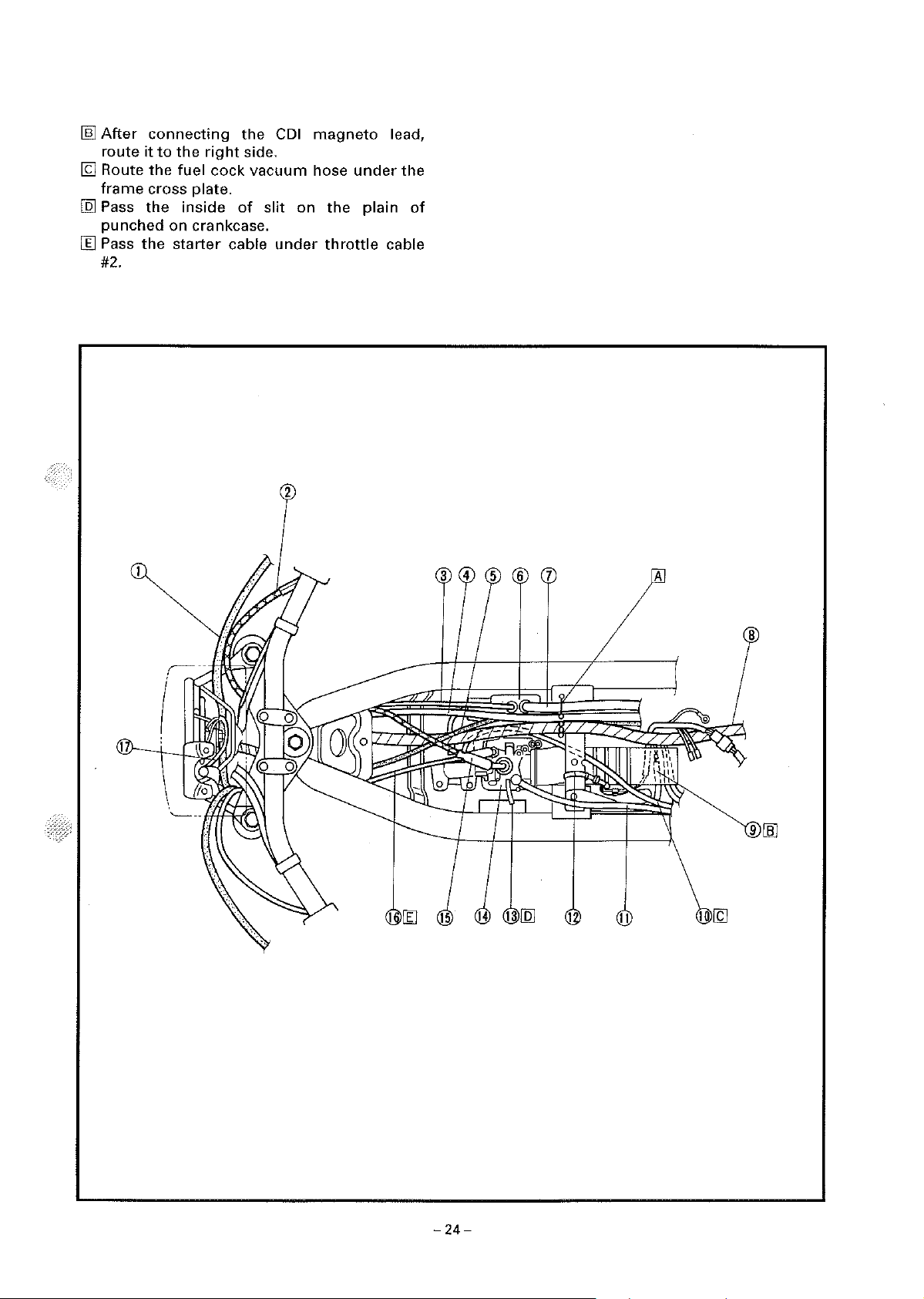
[§]
After
route
19
Route
frame
[Q]
Pass
punched
II]
Pass
#2.
connecting
it
to
the
the
fuel cock vacuum hose
cross plate.
the
inside
on crankcase.
the
starter
right
cable
the
side.
of
slit
CDI
on
under
magneto
under
the
plain
throttle
lead,
the
of
cable
8
9
[ID
-24-

CD
Starter
cable
® Rear brake cable
@ Fuel cock
@Fuse
@ Battery
vaccum
® Fuel hose
(j) Flasher relay
® Flasher relay lead
®
Ignition
@)
Ignition
®
Battery
coil lead
coil
breather
hose
hose
2
@
Spark
@)
CDI
magneto
@
Wire
[!';]
Pass
fender
[ill Fasten
on
lead
[l;J
Fasten
section
plug
lead
harness
the
fuel hose
bracket.
the
the
left, inside section
the
spark
of
the
lead
flasher
frame.
through
relay lead and
plug
lead
the
on
of
frame.
the
inside
of
ignition
right, inside
rear
coil
D
A
11
-
25-
 Loading...