

Yamaha E115A, 115B, 150A, L150A, 175A Owner's Manual
...
OWNER’S MANUAL
E115A
115B
140B
150A
L150A
175A
200A
L200A
60H-28199-E1


EMU01449
E
TO THE OWNER
Thank you for choosing a Yamaha outboard
motor. This Owner’s manual contains information needed for proper operation, maintenance and care. A thorough understanding of these simple instructions will help you
obtain maximum enjoyment from your new
Yamaha. If you have any question about
the operation or maintenance of your outboard motor, please consult a Yamaha
dealer.
In this Owner’s Manual particularly important information is distinguished in the following ways.
Q The Safety Alert Symbol means
ATTENTION! BECOME ALERT!
YOUR SAFETY IS INVOLVED!
w
Failure to follow WARNING instructions
could result in severe injury or death to
the machine operator, a bystander, or a
person inspecting or repairing the outboard motor.
EMU01447
cC
A CAUTION indicates special precautions that must be taken to avoid damage to the outboard motor.
NOTE:
A NOTE provides key information to make
procedures easier or clearer.
* Yamaha continually seeks advancements
in product design and quality. Therefore,
while this manual contains the most current product information available at the
time of printing, there may be minor discrepancies between your machine and
this manual. If there is any question concerning this manual, please consult your
Yamaha dealer.
NOTE:
The E115AE, E115AMH, E115AWH,
200AET, L200AET, and their standard
accessories are used as a base for the
explanations and illustrations in this manual. Therefore, some items may not apply to
every model.
E115A, 115B, 140B, 150A, L150A,
175A, 200A, L200A
OWNER’S MANUAL
©2002 by Yamaha Motor Co., Ltd.
1st Edition, March 2002
All rights reserved.
Any reprinting or unauthorized use
without the written permission of
Yamaha Motor Co., Ltd.
is expressly prohibited.
Printed in Japan

EMU00003
E
CONTENTS
GENERAL INFORMATION
BASIC COMPONENTS
OPERATION
MAINTENANCE
1
2
3
4
TROUBLE RECOVERY
INDEX
READ THIS OWNER’S MANUAL CAREFULLY
BEFORE OPERATING YOUR OUTBOARD MOTOR.
5
6


E
EMU00004
Chapter 1
GENERAL
INFORMATION
IDENTIFICATION NUMBERS
RECORD ............................................... 1-1
Outboard motor serial number ............ 1-1
Key number ........................................ 1-1
LABELS ................................................ 1-2
EC label .............................................. 1-2
EPA label ............................................ 1-2
EMISSION CONTROL
INFORMATION ..................................... 1-3
SAFETY INFORMATION ...................... 1-4
FUELING INSTRUCTIONS ................... 1-6
Gasoline............................................... 1-7
Engine oil ............................................ 1-7
BATTERY REQUIREMENT .................. 1-8
1
2
3
4
PROPELLER SELECTION .................... 1-8
START-IN-GEAR PROTECTION .......... 1-9
5
6
E
YAMAHA MOTOR CO., LTD.
MADE IN JAPAN
PAYS D'ORIGINE JAPON
1
401012
000319
123
YAMAHA
q
EMU00005
IDENTIFICATION NUMBERS
RECORD
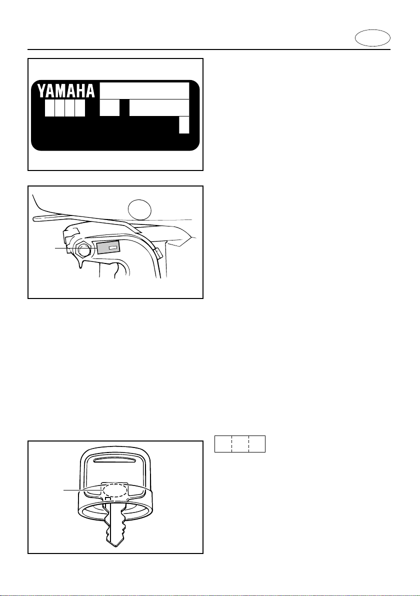
EMU00007
OUTBOARD MOTOR SERIAL
NUMBER
The outboard motor serial number is
stamped on the label attached to the port
side of the clamp-bracket.
Record your outboard motor serial number
in the spaces provided to assist you in
ordering spare parts from your Yamaha
dealer or for reference in case your outboard motor is stolen.
1 Outboard motor serial number
1-1
EMU00008
KEY NUMBER
If a main key switch is equipped with the
motor, the key identification number is
stamped on your key as shown in the illustration. Record this number in the space
provided for reference in case you need a
new key.
1 Key number
000769
YAMAHA MOTOR CO.,LTD.
2500 SHINGAI,IWATA,
SHIZUOKA,JAPAN
NOMINAL POWER
MASS
KW
Kg
EMISSION CONTROL INFORMATION
ENGINE FAMILY :
THIS ENGINE CONFORMS TO 2001 U.S. EPA REGULATIONS FOR MARINE SI ENGINES.
FELs :
SPARK PLUG :
g/kw-hr
IDLE SPEED :
SPARK PLUG GAP (mm) :
rpm IN NEUTRAL
000762
E
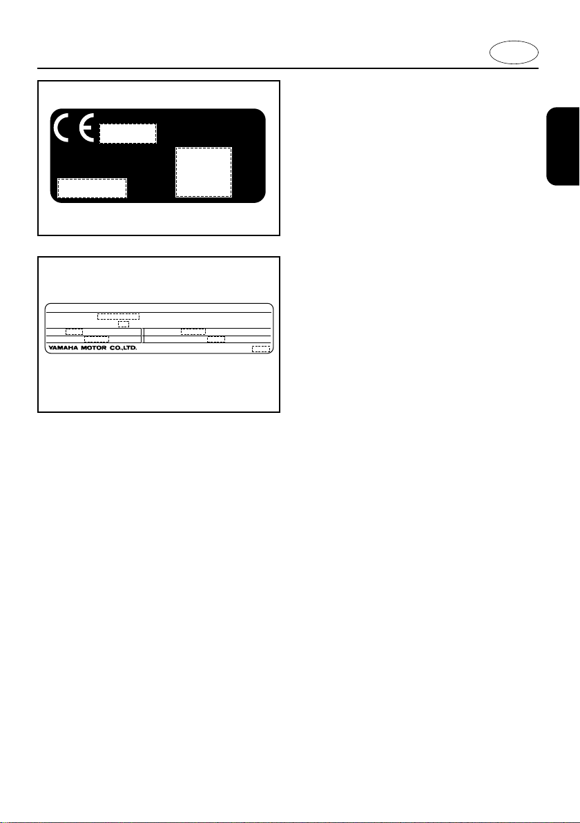
EMU01532
LABELS
EMU01526
EC LABEL
Engines affixed with this label conform to
certain portions of the European Parliament
directive relating to machinery. Refer to the
label and the EC Declaration of Conformity
for more details.
EMU01527
EPA LABEL
Engines affixed with this label conform to
U.S. Environmental Protection Agency
(EPA) regulations for marine SI engines.
Refer to the label for more details.
1-2
E
q
w
001336
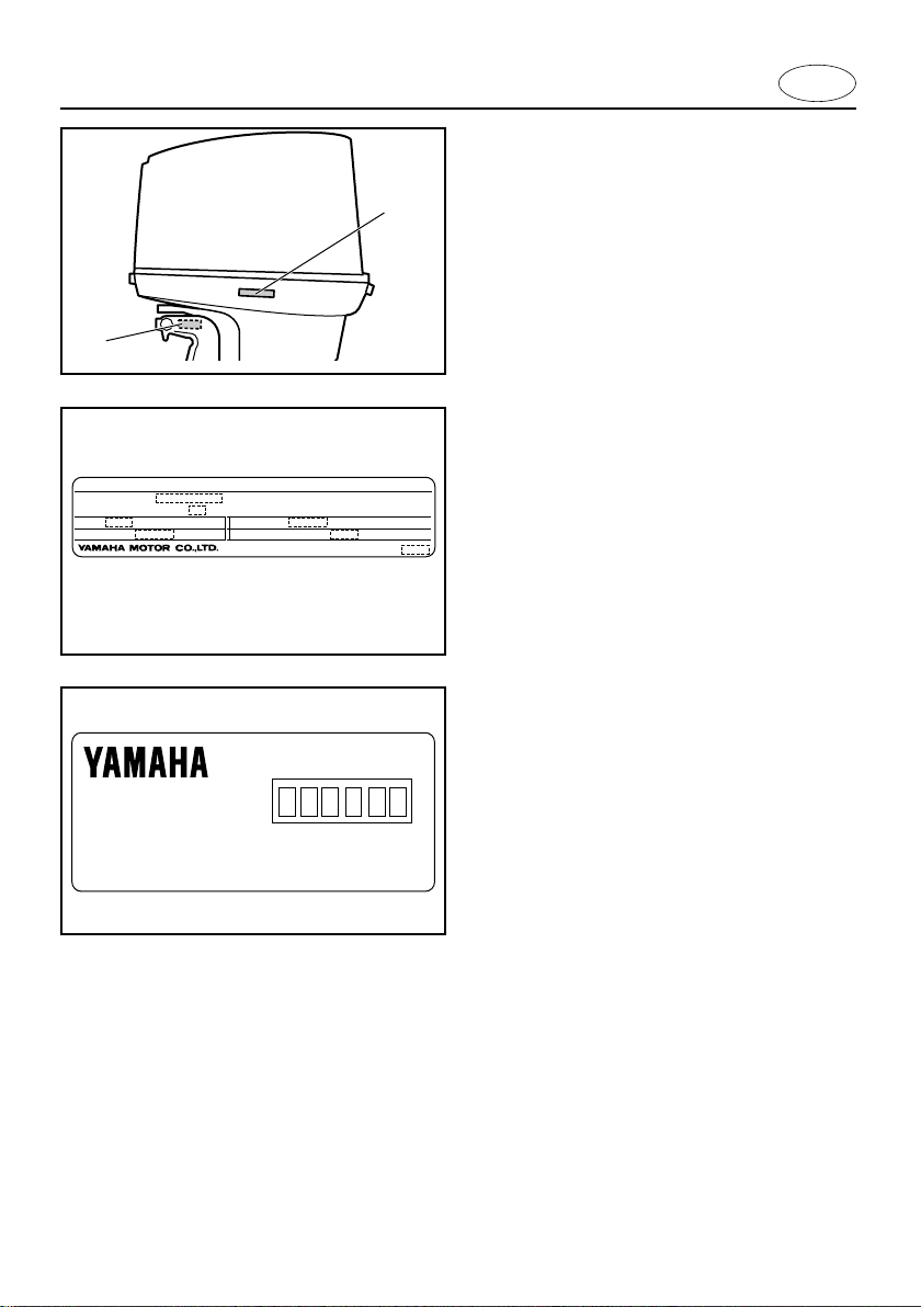
EMU01385
EMISSION CONTROL
INFORMATION
EMU01390
U.S. INSULAR AREAS
Engines affixed with the label pictured
below conform to U.S. Environmental
Protection Agency (EPA) regulations for
marine SI engines. See the label affixed to
your engine for details.
EMISSION CONTROL INFORMATION
ENGINE FAMILY :
THIS ENGINE CONFORMS TO 2001 U.S. EPA REGULATIONS FOR MARINE SI ENGINES.
FELs :
SPARK PLUG :
g/kw-hr
IDLE SPEED :
SPARK PLUG GAP (mm) :
rpm IN NEUTRAL
000762
Manufactured:
1 Emission control information label
Approval label of Emission control certificate
This label is attached to the bottom cowling.
Existing Technology ; N/A
2 Manufactured date label
Manufactured date label
This label is attached to the clamp bracket
or the swivel bracket.
1-3

E
EMU00918
QSAFETY INFORMATION
8 Before mounting or operating the out-
board motor, read this entire manual.
Reading it should give you an understanding of the motor and its operation.
8 Before operating the boat, read any
owner’s or operator’s manuals supplied
with it and all labels. Be sure you understand each item before operating.
8 Do not overpower the boat with this out-
board motor. Overpowering the boat
could result in loss of control. The rated
power of the outboard should be equal to
or less than the rated horsepower capacity of the boat. If the rated horsepower
capacity of the boat is unknown, consult
the dealer or boat manufacturer.
8 Do not modify the outboard. Modifications
could make the motor unfit or unsafe to
use.
8 Never operate after drinking alcohol or
taking drugs. About 50% of all boating
fatalities involve intoxication.
8 Have an approved personal flotation
device (PFD) on board for every occupant. It is a good idea to wear a PFD
whenever boating. At a minimum, children and non-swimmers should always
wear PFDs, and everyone should wear
PFDs when there are potentially hazardous boating conditions.
8 Gasoline (Petrol) is highly flammable, and
its vapors are flammable and explosive.
Handle and store gasoline (Petrol) carefully. Make sure there are no gas fumes
or leaking fuel before starting the engine.
1-4

E
8 This product emits exhaust gases which
contain carbon monoxide, a colorless,
odorless gas which may cause brain
damage or death when inhaled.
Symptoms include nausea, dizziness,
and drowsiness. Keep cockpit and cabin
areas well ventilated. Avoid blocking
exhaust outlets.
8 Check throttle, shift, and steering for
proper operation before starting the
engine.
8 Attach the engine stop switch lanyard to a
secure place on your clothing, or your
arm or leg while operating. If you accidentally leave the helm, the lanyard will pull
from the switch, stopping the engine.
8 Know the marine laws and regulations
where you will be boating - and obey
them.
8 Stay informed about the weather. Check
weather forecasts before boating. Avoid
boating in hazardous weather.
8 Tell someone where you are going: leave
a Float Plan with a responsible person.
Be sure to cancel the Float Plan when
you return.
8 Use common sense and good judgment
when boating. Know your abilities, and be
sure you understand how your boat handles under the different boating conditions
you may encounter. Operate within your
limits, and the limits of your boat. Always
operate at safe speeds, and keep a careful watch for obstacles and other traffic.
8 Always watch carefully for swimmers dur-
ing the engine operation.
8 Stay away from swimming areas.
8 When a swimmer is in the water near you
shift into neutral and shut off the engine.
1-5

E
EMU00016
FUELING INSTRUCTIONS
w
GASOLINE AND ITS VAPORS ARE HIGHLY FLAMMABLE AND EXPLOSIVE!
8 Do not smoke when refueling, and
keep away from sparks, flames, or
other sources of ignition.
8 Stop engine before refueling.
8 Refuel in a well-ventilated area. Refuel
portable fuel tanks off the boat.
8 Take care not to spill gasoline. If gaso-
line spills, wipe it up immediately with
dry rags.
8 Do not overfill the fuel tank.
8 Tighten the filler cap securely after
refueling.
8 If you should swallow some gasoline
inhale a lot of gasoline vapor, or get
gasoline in your eyes, get immediate
medical attention.
8 If any gasoline spills onto your skin,
immediately wash with soap and
water. Change clothing if gasoline
spills on it.
8 Touch the fuel nozzle to the filler open-
ing or funnel to help prevent electrostatic sparks.
cC
Use only new clean gasoline which has
been stored in clean containers and is
not contaminated with water or foreign
matter.
1-6

E
EMU01799
GASOLINE
Recommended gasoline:
Regular unleaded gasoline
If knocking or pinging occurs, use a different brand of gasoline or premium unleaded
fuel. If unleaded gasoline is not available,
then premium gasoline can be used.
EMU01356
ENGINE OIL
Recommended engine oil:
YAMALUBE, TWO STROKE MOTOR
OIL FOR MARINE
If the recommended engine oil is not available, another 2-stroke engine oil with a
NMMA-certified TC-W3 rating may be used.
1-7

E
901015
UPPER LEVEL
LOWER LEVEL
EMU01775
BATTERY REQUIREMENT
cC
Do not use a battery that does not meet
the specified capacity. If a battery which
does not meet specifications is used, the
electric system could perform poorly or
be overloaded, causing electric system
damage.
For electric start models, choose a battery
which meets the following specifications.
EMU01857
Minimum cold cranking amps (CCA/EN):
430 amps at -18°C (-0.4°F)
Minimum rated capacity (20HR/IEC):
70 A·h
EMU01395
PROPELLER SELECTION
The performance of your outboard motor
will be critically affected by your choice of
propeller, as an incorrect choice could
adversely affect performance and could
also seriously damage the motor. Engine
speed depends on the propeller size and
boat load. If engine speed is too high or too
low for good engine performance, this will
have an adverse effect on the engine.
Yamaha outboard motors are fitted with
propellers chosen to perform well over a
range of applications, but there may be
uses where a propeller with a different pitch
would be more appropriate. For a greater
operating load, a smaller-pitch propeller is
more suitable as it enables the correct
engine speed to be maintained. Conversely,
a larger-pitch propeller is more suitable for
a smaller operating load.
1-8
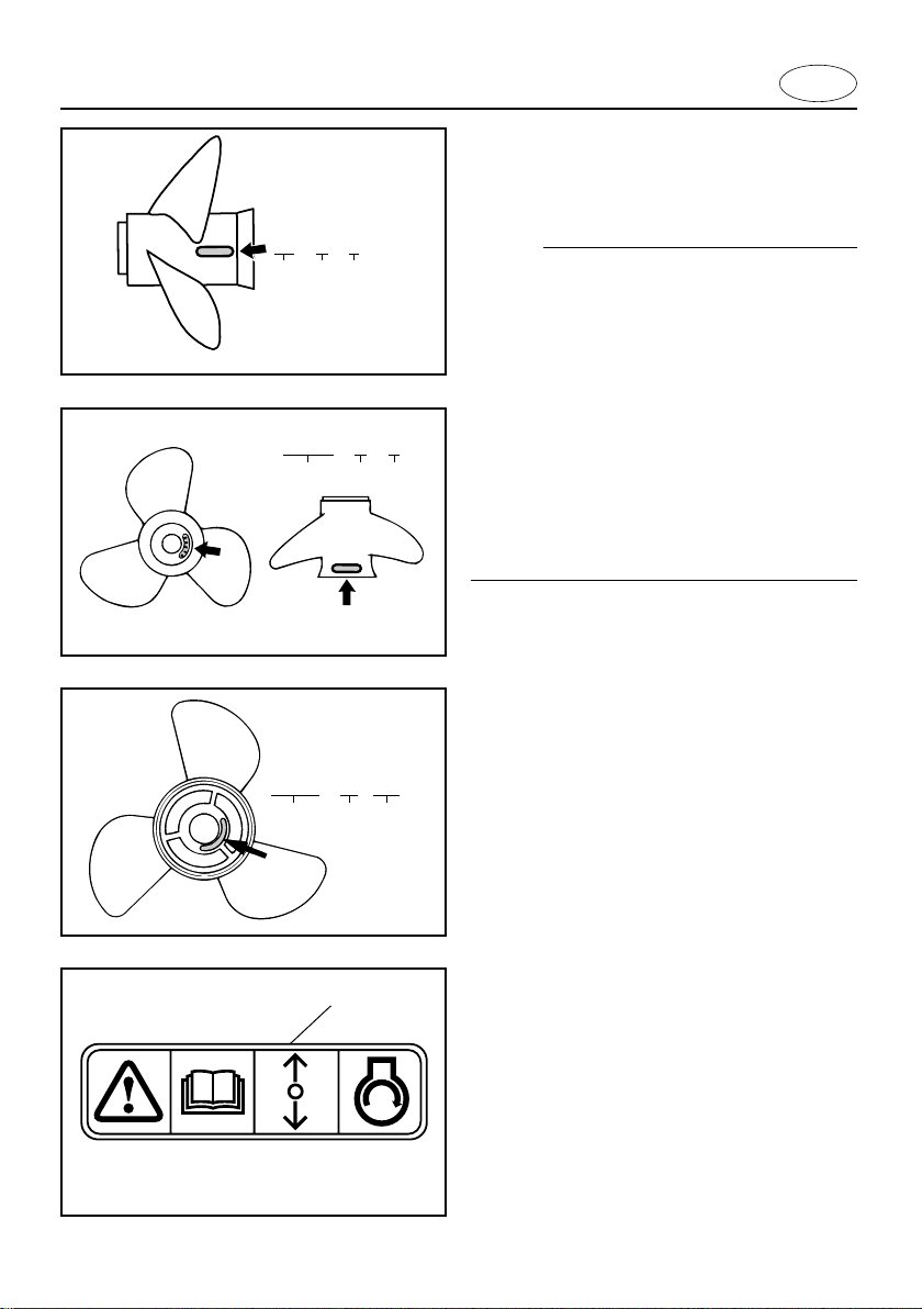
13 x 17 - K
qwe
000933
14-1/2 x 17 - M
qwe
E
Yamaha dealers stock a range of propellers, and can advise you and install a
propeller on your outboard that is best suited to your application.
NOTE:
At full throttle and under a maximum boat
load, the engine’s rpm should be within the
upper half of the full throttle operating
range, as listed in “SPECIFICATIONS” on
page 4-1. Select a propeller which fulfills
this requirement.
If operating under conditions which allow
the engine’s rpm to rise above the maximum recommended range (such as light
boat loads), reduce the throttle setting to
maintain the rpm in the proper operating
range.
13-3/4 x 17 - ML
qwe
q
602022
602033
000376
1 Propeller diameter (in inches)
2 Propeller pitch (in inches)
3 Type of propeller (propeller mark)
Refer to the section “CHECKING PROPELLER” for instructions on propeller
removal and installation.
EMU01208
START-IN-GEAR PROTECTION
Yamaha outboard motors which have the
pictured label 1 affixed to them or Yamaha
approved remote control units are equipped
with start-in-gear protection device(s). This
feature permits the engine to be started
only when it is Neutral. Always select
Neutral before starting the engine.
1-9

E
EMU00037
Chapter 2
BASIC COMPONENTS
MAIN COMPONENTS ........................... 2-1
OPERATIONS OF CONTROLS AND
OTHER FUNCTIONS ............................ 2-5
Fuel tank ............................................. 2-5
Gear shift lever ................................... 2-6
Engine stop lanyard switch ................. 2-6
Choke knob ......................................... 2-7
Manual injection knob ......................... 2-7
Recoil starter handle ........................... 2-7
Main switch ......................................... 2-8
Tiller handle ........................................ 2-8
Remote control ................................. 2-10
Steering friction adjusting screw ....... 2-16
Trim tab ............................................. 2-17
Trim angle adjusting rod ................... 2-17
Tachometer ....................................... 2-18
Trim meter ........................................ 2-18
Digital hour meter ............................. 2-18
Tilt lock mechanism .......................... 2-19
Tilt support lever ............................... 2-20
Top cowling lock levers ..................... 2-20
WARNING SYSTEM ........................... 2-21
Overheat warning ............................. 2-21
1
2
3
4
5
6
EMU01206
!3
!4
!0
o
i
w
e
r
t
y
u
q
!1
!2
E115AMH, E115AWH
E
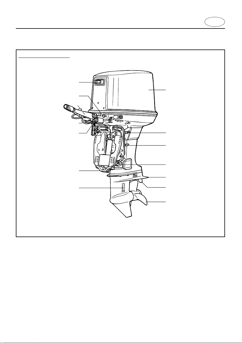
MAIN COMPONENTS
1 Top cowling
2 Tilt support lever
3 Tilt lock lever
4 Trim angle adjusting rod
5 Anti-cavitation plate
6 Trim tab (Anode)
7 Propeller
8 Cooling water inlet
9 Anode
0 Engine stop switch
2-1
*
q Main switch
w Tiller handle
e Manual injection knob
r Recoil starter handle
* May not be exactly as shown; also may not be
included as standard equipment on all models.
EMU01206
o
i
u
y
t
r
e
q
w
!0
!1
E115AE, 115BE
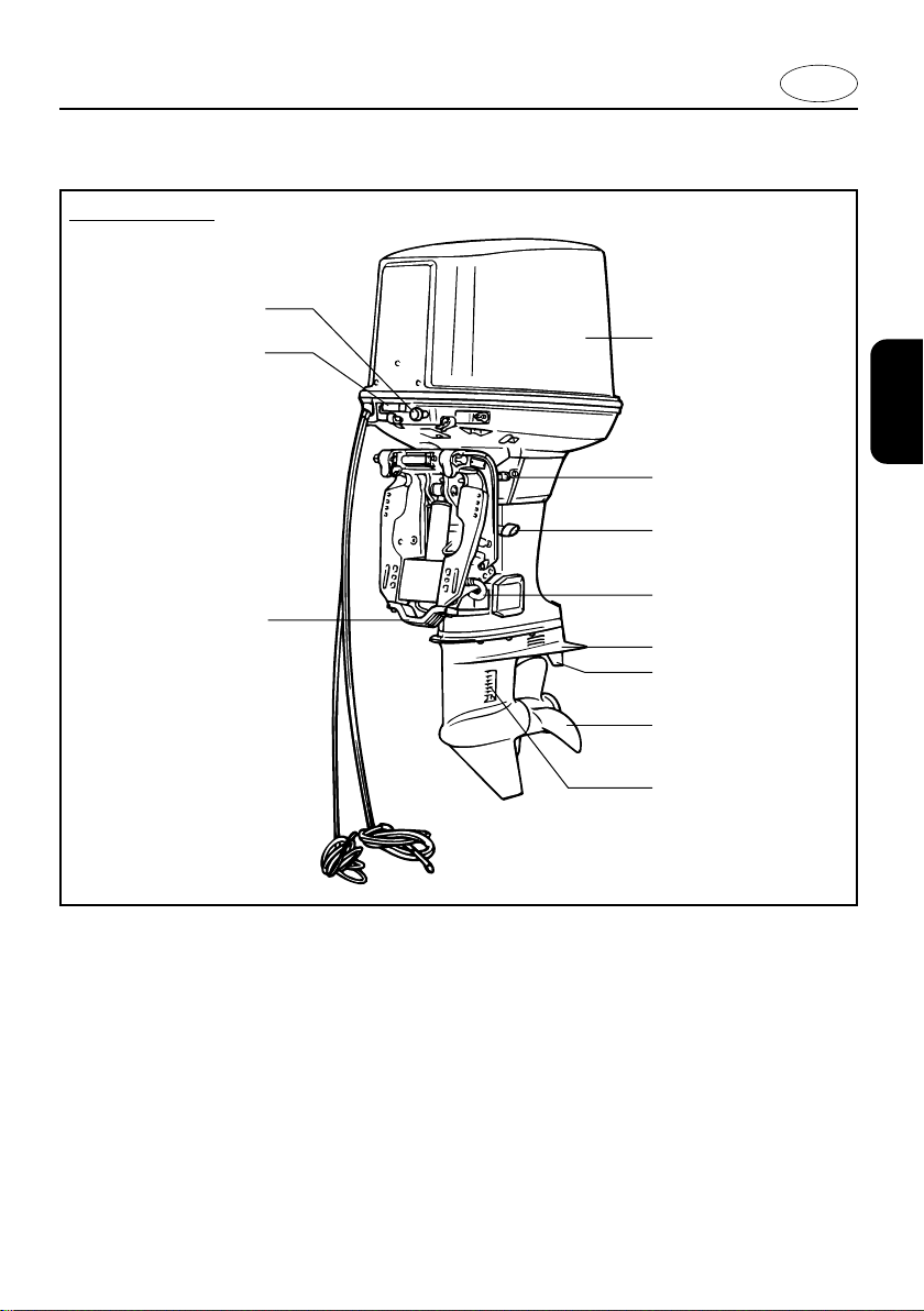
E
MAIN COMPONENTS
1 Top cowling
2 Tilt support lever
3 Tilt lock lever
4 Trim angle adjusting rod
5 Anti-cavitation plate
6 Trim tab (Anode)
7 Propeller
8 Cooling water inlet
9 Anode
0 Cowling lock lever
q Choke knob
* May not be exactly as shown; also may not be
included as standard equipment on all models.
2-2

EMU01206
2
w
1
2
3
4
5
6
7
8
9
0
q
MAIN COMPONENTS
E115AET, 115BET, 140BET, 150AET, L150AET, 175AET, 200AET, L200AET
E
1 Top cowling
2 Cowling lock levers
3 Anti-cavitation plate
4 Trim tab(Anode)
5 Propeller
6 Cooling water inlet
7 Anode
8 Clamp bracket
9 Tilt support lever
0 Power trim/tilt switch
q Fuel joint
w Choke knob
2-3
* May not be exactly as shown; also may not be
included as standard equipment on all models.

EMU01206
i
w
e
r
t
y
q
u
YAMAHA
HOUR
YAMAHA
YAMAHA
x1000 r/min
7
6
5
43
1
2
E
MAIN COMPONENTS
*
1 Remote control box (side mount type)
*
2 Remote control box (binnacle mount type)
*
3 Switch panel (for use with 2)
*
4 Tachometer
*
5 Trim meter
*
6 Digital hour meter
*
7 Remote control cable
*
8 Fuel tank
* May not be exactly as shown; also may not be
included as standard equipment on all models.
2-4
E
902016
e
q
r
w
EMU00039
OPERATIONS OF CONTROLS
AND
OTHER FUNCTIONS
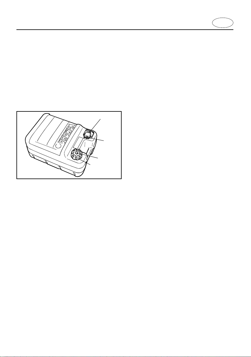
EMU01465
FUEL TANK
If your model included a portable fuel tank,
its parts and functions are as follows.
1 Fuel hose joint
2 Fuel meter (if equipped)
3 Fuel tank cap
4 Air vent screw (if equipped)
EMU00042
Fuel Hose Joint
This connector is provided for connecting or
disconnecting fuel hose.
EMU00045
Fuel Tank Cap
This cap is for filling fuel. To remove it, turn
it counterclockwise.
2-5
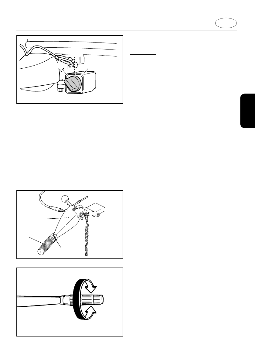
EMU00046
Air Vent Screw
This screw is on the fuel tank cap. To
loosen it, turn it counterclockwise.
E
507014
12
3
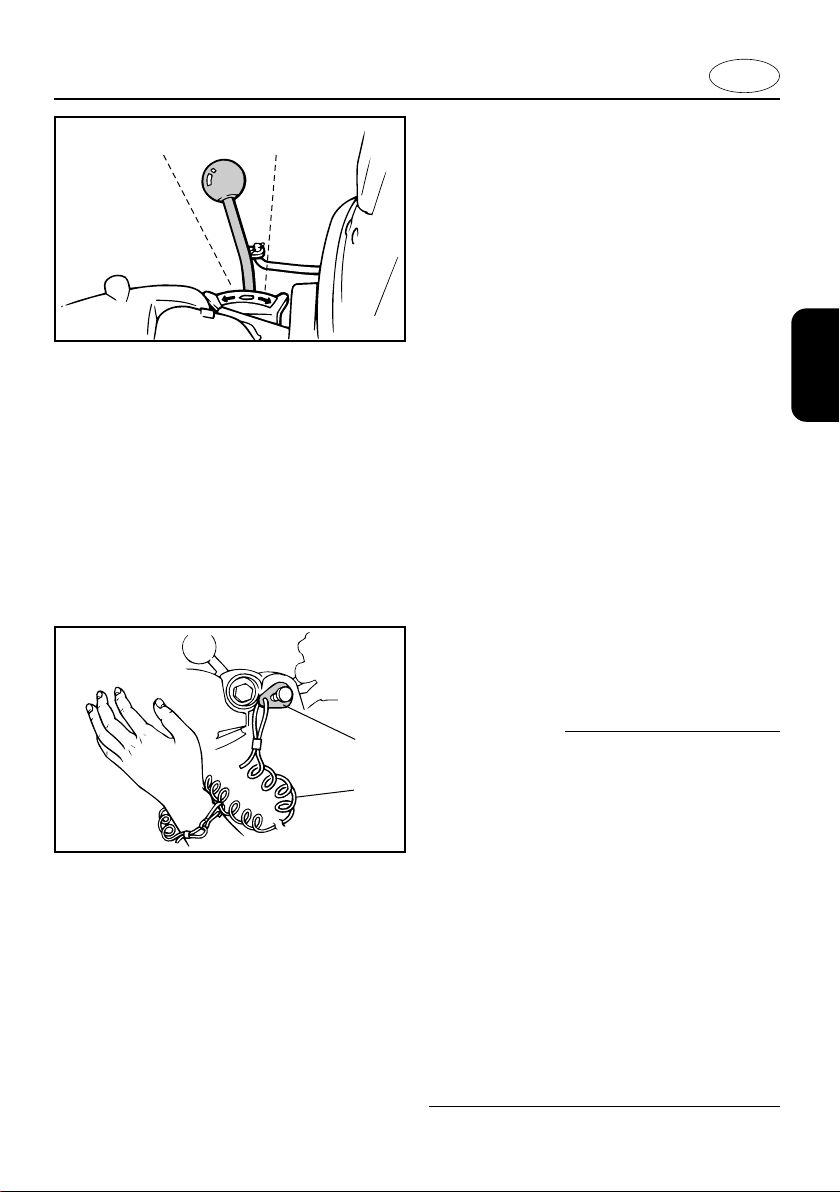
EMU00051
GEAR SHIFT LEVER (for Tiller
control model)
Turning the gear-shift lever towards you
engages the clutch with the forward gear so
that the boat moves ahead. Turning the
lever away from you engages the reverse
gear so that the boat moves astern.
1 Neutral
2 Forward
3 Reverse
EMU00931
ENGINE STOP LANYARD SWITCH
(for Tiller control model)
The lock-plate 1 must be attached to the
engine stop lanyard switch for the engine to
run. The lanyard 2 should be attached to a
secure place on the operator’s clothing, or
arm or leg. Should the operator fall overboard or leave the helm, the lanyard will pull
out the lock plate, stopping ignition to the
engine. This will prevent the boat from running away under power.
w
q
w
000974
8 Attach the lanyard to a secure place
on your clothing, your arm or leg while
operating.
8 Do not attach the lanyard to clothing
that could tear loose. Do not route the
lanyard in such a way that it could
become entangled, preventing it from
functioning.
8 Avoid accidentally pulling the lanyard
during normal operation. Loss of
engine power means the loss of most
steering control. Also, without engine
power, the boat could slow rapidly.
This could cause people and objects
in the boat to be thrown forward.
2-6

305034
001310
E
NOTE:
The engine cannot be started with the lockplate removed.
EMU00055
CHOKE KNOB
Pulling out this knob (setting it to ON) supplies a rich mixture required to start the
engine.
NOTE:
The choke knob for Remote control model
has the same function as the choke switch
on the remote control box.
EMU01703
MANUAL INJECTION KNOB
E115AMH, E115AWH
The manual injection knob is used to supply
a rich fuel mixture to the carburetor when
starting the engine. To use the manual
injection knob, fully pull out the knob firmly.
Release the knob to allow it to automatically
return to its home position. For further information, see Chapter 3, “Starting engine.”
EMU00059
RECOIL STARTER HANDLE (If
equipped)
Pull the handle gently until resistance is felt.
Then vigorously pull the handle straight out
to crank the engine to start it.
2-7
209015
000530
OFF
ON
START
q
e
w
000952
E
EMU01292
MAIN SWITCH
E115AWH
The main switch controls the ignition system; its operation is described below.
8 OFF
Electrical circuits switched off.
(The key can be removed.)
8 ON
Electrical circuits switched on.
(The key cannot be removed.)
8 START
Starter-motor will turn and start engine.
(When the key is released, it returns automatically to “ON”.)
EMU00062
TILLER HANDLE (for Tiller control
model)
Moving the tiller handle sideways to adjust
the steering direction. In addition, this handle contains the functions as follows.
1 Throttle control grip
2 Throttle indicator
3 Throttle friction adjusting knob/screw
EMU00065
Throttle Control Grip
The throttle control grip is on the tiller handle. Turn the grip counterclockwise to
increase speed and clockwise to decrease
speed.
000529
2-8
502025
q
E
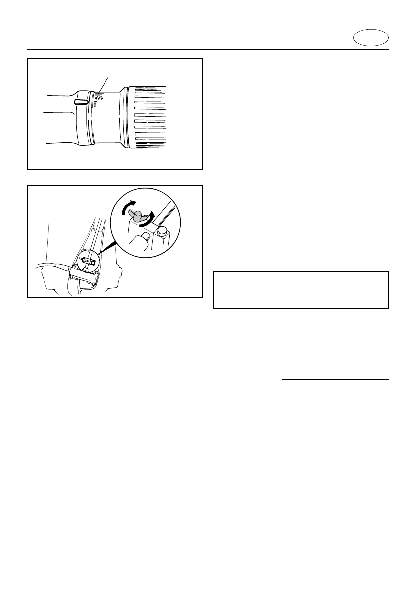
EMU00067
Throttle Indicator
The fuel consumption curve on the throttle
indicator shows the relative amount of fuel
consumed for each throttle position.
Choose the setting that offers the best performance and fuel economy for the desired
operation.
000559
1 Throttle indicator
EMU01293
Throttle friction adjusting screw/ knob
A friction device in the tiller handle provide
resistance to movement of the throttle grip.
This is adjustable for operator preference.
An adjusting screw/knob is located within
the tiller handle.
Resistance Knob/Screw
Increase Turn clockwise
Decrease Turn counterclockwise
When constant speed is desired, tighten the
adjusting screw/bolt to maintain the desired
throttle setting.
w
Do not over tighten the friction adjusting
screw/ knob.
If there is too much resistance, it may be
difficult to move the throttle grip, which
could result in an accident.
2-9

E
000322
w
q
e
t
y
u
i
A
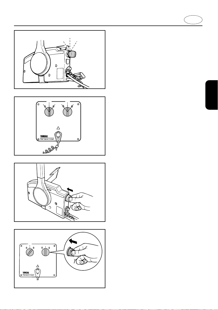
EMU01691
REMOTE CONTROL
Both the shifter and the throttle are actuated
by the remote control lever. Additionally, the
remote control also has the electrical
switches.
å Side mount remote control box
∫ Binnacle mount remote control box
ç Switch panel (for use with ∫)
1 Remote control lever
B
q
u
i
2 Neutral interlock trigger
3 Neutral throttle lever
4 Free accelerator
5 Main switch / choke switch
6 Engine stop lanyard switch
7 Power trim and tilt switch
8 Throttle friction adjusting screw
u
r
001276
C
ON
ON
STARTOFF
STARTOFF
t
y
001277
2-10

R
N
F
q
w
e
r
t
y
u
u
t
r
y
701031
u
w
E
EMU00098
Remote Control Lever
Moving the lever forward from the Neutral
position engages Forward gear. Pulling the
lever back from Neutral engages Reverse.
The engine will continue to run at idle until
the lever is moved about 35° (a detent can
be felt). Moving the lever farther opens the
throttle, and the engine will begin to accelerate.
1 Neutral
q
rr
e
tty
y
u
702032
UP
DN
2 Forward
3 Reverse
4 Shift
5 Fully closed
6 Throttle
7 Fully open
EMU00099
Neutral Interlock Trigger
To shift out of Neutral, the neutral interlock
trigger of the remote control lever must first
be pulled up.
2-11
EMU00100
Neutral Throttle Lever
000323
N
q
w
000324
To open the throttle without shifting into
either Forward or Reverse, place the
remote control lever in the Neutral position
and lift the neutral throttle lever.
NOTE:
The neutral throttle lever will operate only
when the remote control lever is in Neutral.
The remote control lever will operate only
when the neutral throttle lever is in the
closed position.
1 Fully open
2 Fully closed
E
ON
STARTOFF
701021
EMU00101
Main switch
The main switch controls the ignition system; its operation is described below.
8 OFF
Electrical circuits switched off.
(The key can be removed.)
8 ON
Electrical circuits switched on.
(The key cannot be removed.)
8 START
ON
ON
STARTOFF
STARTOFF
001242
Starter-motor will turn and start engine.
(When the key is released, it returns automatically to “ON”.)
EMU00102
Choke Switch
While the main switch is being pressed in at
“ON” or “START”, the choke system will
switch on, to supply a rich mixture required
to start the engine. (When the key is
released, it will switch off automatically.)
701055
ON
STARTOFF
703031
2-12
000569
q
w
w
E
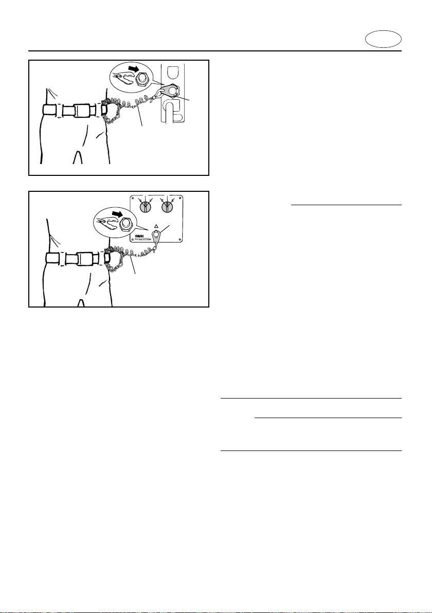
EMU00934
Engine Stop Lanyard Switch
The lock-plate 1 must be attached to the
engine stop lanyard switch for the engine to
run. The lanyard 2 should be attached to a
secure place on the operator’s clothing, or
arm or leg. Should the operator fall overboard or leave the helm, the lanyard will pull
out the lock plate, stopping ignition to the
engine. This will prevent the boat from run-
ON
ON
STARTOFF
STARTOFF
q
000715
ning away under power.
w
8 Attach the lanyard to a secure place
on your clothing, your arm or leg while
operating.
8 Do not attach the lanyard to clothing
that could tear loose. Do not route the
lanyard in such a way that it could
become entangled, preventing it from
functioning.
8 Avoid accidentally pulling the lanyard
during normal operation. Loss of
engine power means the loss of most
steering control. Also, without engine
power, the boat could slow rapidly.
This could cause people and objects
in the boat to be thrown forward.
2-13
NOTE:
The engine cannot be started with the lockplate removed.
 Loading...