

Page 1
EnglishItaliano Español Français Deutsch
MIXING CONSOLE
Owner’s Manual
Bedienungsanleitung
Mode d’emploi
Manual de instrucciones
Manuale di istruzioni
EN
DE
FR
ES
RU
ZH
JA
IT
Page 2

FCC INFORMATION (U.S.A.)
1. IMPORTANT NOTICE: DO NOT MODIFY THIS UNIT!
This product, when installed as indicated in the instructions contained in this manual, meets FCC requirements. Modifications
not expressly approved by Yamaha may void your authority,
granted by the FCC, to use the product.
2. IMPORTANT:
and/or another product use only high quality shielded cables.
Cable/s supplied with this product MUST be used. Follow all
installation instructions. Failure to follow instructions could void
your FCC authorization to use this product in the USA.
3. NOTE:
the requirements listed in FCC Regulations, Part 15 for Class
“B” digital devices. Compliance with these requirements provides a reasonable level of assurance that your use of this product in a residential environment will not result in harmful
interference with other electronic devices. This equipment generates/uses radio frequencies and, if not installed and used
according to the instructions found in the users manual, may
cause interference harmful to the operation of other electronic
devices. Compliance with FCC regulations does not guarantee
* This applies only to products distributed by YAMAHA CORPORATION OF AMERICA. (class B)
When connecting this product to accessories
This product has been tested and found to comply with
that interference will not occur in all installations. If this product
is found to be the source of interference, which can be determined by turning the unit “OFF” and “ON”, please try to eliminate the problem by using one of the following measures:
Relocate either this product or the device that is being affected
by the interference.
Utilize power outlets that are on different branch (circuit breaker
or fuse) circuits or install AC line filter/s.
In the case of radio or TV interference, relocate/reorient the
antenna. If the antenna lead-in is 300 ohm ribbon lead, change
the lead-in to co-axial type cable.
If these corrective measures do not produce satisfactory results,
please contact the local retailer authorized to distribute this type
of product. If you can not locate the appropriate retailer, please
contact Yamaha Corporation of America, Electronic Service
Division, 6600 Orangethorpe Ave, Buena Park, CA90620
The above statements apply ONLY to those products distributed
by Ya maha Corporation of America or its subsidiaries.
COMPLIANCE INFORMATION STATEMENT
(DECLARATION OF CONFORMITY PROCEDURE)
Responsible Party : Yamaha Corporation of America
Address : 6600 Orangethorpe Ave., Buena Park, Calif. 90620
Telephone : 714-522-9011
Type of Equipment : MIXING CONSOLE
Model Name : IM8-40/IM8-32/IM8-24
This device complies with Part 15 of the FCC Rules.
Operation is subject to the following two conditions:
1) this device may not cause harmful interference, and
2) this device must accept any interference received including interference
that may cause undesired operation.
See user manual instructions if interference to radio reception is suspected.
* This applies only to products distributed by
YAMAHA CORPORATION OF AMERICA.
(FCC DoC)
Page 3
CAUTION
RISK OF ELECTRIC SHOCK
DO NOT OPEN
CAUTION: TO REDUCE THE RISK OF
ELECTRIC SHOCK, DO NOT REMOVE
COVER (OR BACK). NO USER-SERVICEABLE
PARTS INSIDE. REFER SERVICING TO
QUALIFIED SERVICE PERSONNEL.
The above warning is located on the rear of the unit.
Explanation of Graphical Symbols
The lightning flash with arrowhead symbol
within an equilateral triangle is intended to alert
the user to the presence of uninsulated
“dangerous voltage” within the product’s
enclosure that may be of sufficient magnitude to
constitute a risk of electric shock to persons.
The exclamation point within an equilateral
triangle is intended to alert the user to the
presence of important operating and maintenance
(servicing) instructions in the literature
accompanying the product.
IMPORTANT SAFETY INSTRUCTIONS
1 Read these instructions.
2Keep these instructions.
3 Heed all warnings.
4 Follow all instructions.
5 Do not use this apparatus near water.
6 Clean only with dry cloth.
7 Do not block any ventilation openings. Install in
accordance with the manufacturer’s instructions.
8 Do not install near any heat sources such as radiators,
heat registers, stoves, or other apparatus (including
amplifiers) that produce heat.
9 Do not defeat the safety purpose of the polarized or
grounding-type plug. A polarized plug has two blades
with one wider than the other. A grounding type plug has
two blades and a third grounding prong. The wide blade
or the third prong are provided for your safety. If the
provided plug does not fit into your outlet, consult an
electrician for replacement of the obsolete outlet.
10 Protect the power cord from being walked on or pinched
particularly at plugs, convenience receptacles, and the
point where they exit from the apparatus.
WARNING
TO REDUCE THE RISK OF FIRE OR ELECTRIC SHOCK, DO NOT EXPOSE THIS APPARATUS TO RAIN OR MOISTURE.
11 Only use attachments/accessories specified by the
manufacturer.
12 Use only with the cart, stand,
tripod, bracket, or table specified
by the manufacturer, or sold with
the apparatus. When a cart is
used, use caution when moving
the cart/apparatus combination to
avoid injury from tip-over.
13 Unplug this apparatus during
lightning storms or when unused for long periods of
time.
14 Refer all servicing to qualified service personnel.
Servicing is required when the apparatus has been
damaged in any way, such as power-supply cord or plug
is damaged, liquid has been spilled or objects have
fallen into the apparatus, the apparatus has been
exposed to rain or moisture, does not operate normally,
or has been dropped.
(UL60065_03)
Page 4
PRECAUTIONS
PLEASE READ CAREFULLY BEFORE PROCEEDING
* Please keep this manual in a safe place for future reference.
English
WARNING
Always follow the basic precautions listed below to avoid the possibility of serious injury or even death from electrical
shock, short-circuiting, damages, fire or other hazards. These precautions include, but are not limited to, the following:
Power supply/Power cord
• Only use the voltage specified as correct for the device. The required voltage is
printed on the name plate of the device.
• Use only the specified power supply (PW8 or an equivalent recommended by
Yamaha).
• Do not place the power cord near heat sources such as heaters or radiators, and
do not excessively bend or otherwise damage the cord, place heavy objects on
it, or place it in a position where anyone could walk on, trip over, or roll anything
over it.
Do not open
• Do not open the device or attempt to disassemble the internal parts or modify
them in any way. The device contains no user-serviceable parts. If it should
appear to be malfunctioning, discontinue use immediately and have it inspected
by qualified Yamaha service personnel.
Water warning
• Do not expose the device to rain, use it near water or in damp or wet conditions,
or place containers on it containing liquids which might spill into any openings.
If any liquid such as water seeps into the device, turn off the power immediately
and unplug the power cord from the AC outlet. Then have the device inspected
by qualified Yamaha service personnel.
• Never insert or remove an electric plug with wet hands.
If you notice any abnormality
• If the power cord or plug becomes frayed or damaged, or if there is a sudden
loss of sound during use of the device, or if any unusual smells or smoke
should appear to be caused by it, immediately turn off the power switch,
disconnect the electric plug from the outlet, and have the device inspected by
qualified Yamaha service personnel.
• If this device or power supply should be dropped or damaged, immediately turn
off the power switch, disconnect the electric plug from the outlet, and have the
device inspected by qualified Yamaha service personnel.
CAUTION
Always follow the basic precautions listed below to avoid the possibility of physical injury to you or others, or damage
to the device or other property. These precautions include, but are not limited to, the following:
Power supply/Power cord
• Remove the electric plug from the outlet when the device is not to be used for
extended periods of time, or during electrical storms.
• When removing the electric plug from the device or an outlet, always hold the
plug itself and not the cord. Pulling by the cord can damage it.
Location
• When transporting or moving the device, always use two or more people.
Attempting to lift the device by yourself may damage your back, result in other
injury, or cause damage to the device itself.
• Before moving the device, remove all connected cables.
•Avoid setting all equalizer controls and faders to their maximum. Depending on
the condition of the connected devices, doing so may cause feedback and may
damage the speakers.
• Do not expose the device to excessive dust or vibrations, or extreme cold or heat
(such as in direct sunlight, near a heater, or in a car during the day) to prevent
the possibility of panel disfiguration or damage to the internal components.
• Do not place the device in an unstable position where it might accidentally fall
over.
• Do not use the device in the vicinity of a TV, radio, stereo equipment, mobile
phone, or other electric devices. Doing so may result in noise, both in the device
itself and in the TV or radio next to it.
Connections
• Before connecting the device to other devices, turn off the power for all devices.
Before turning the power on or off for all devices, set all volume levels to
minimum.
Handling caution
• When turning on the AC power in your audio system, always turn on the power
amplifier LAST, to avoid speaker damage. When turning the power off, the power
amplifier should be turned off FIRST for the same reason.
• Do not insert your fingers or hands in any gaps or openings on the device.
•Avoid inserting or dropping foreign objects (paper, plastic, metal, etc.) into any
gaps or openings on the device. If this happens, turn off the power immediately
and unplug the power cord from the AC outlet. Then have the device inspected
by qualified Yamaha service personnel.
• Do not apply oil, grease, or contact cleaner to the faders. Doing so may cause
problems with electrical contact or fader motion.
• Do not use the headphones or speakers for a long period of time at a high or
uncomfortable volume level, since this can cause permanent hearing loss. If you
experience any hearing loss or ringing in the ears, consult a physician.
• Do not rest your weight on the device or place heavy objects on it, and avoid use
excessive force on the buttons, switches or connectors.
(5)-5
1/2
4
Owner’s Manual
Page 5

5
XLR-type connectors are wired as follows (IEC60268 standard): pin 1: ground, pin 2: hot (+), and pin 3: cold (-).
Insert TRS phone jacks are wired as follows: sleeve: ground, tip: send, and ring: return.
Yamaha cannot be held responsible for damage caused by improper use or modifications to the device, or data that is lost or destroyed.
Always turn the power off when the device is not in use.
The performance of components with moving contacts, such as switches, volume controls, and connectors, deteriorates over time. Consult qualified Yamaha service
personnel about replacing defective components.
SPECIAL NOTICES
• This manual is the exclusive copyright of Yamaha Corporation.
• The software included in the accessory disk and the copyrights thereof are under exclusive ownership by Steinberg Media Technologies GmbH.
• Use of the software and this manual is governed by the license agreement which the purchaser fully agrees to upon breaking the seal of the software packaging. (Please
read carefully the Software Licensing Agreement at the end of this manual before installing the application.)
• Copying of the software or reproduction of this manual in whole or in part by any means is expressly forbidden without the written consent of the manufacturer.
•Yamaha makes no representations or warranties with regard to the use of the software and documentation and cannot be held responsible for the results of the use of this
manual and the software.
• This disk containing the software is not meant for use with an audio/visual system (CD player, DVD player, etc.). Do not attempt to use the disk on equipment other than a
computer.
• Future upgrades of application and system software and any changes in specifications and functions will be announced separately.
The illustrations and LCD screens as shown in this manual are for instructional purposes only, and may appear somewhat different from those on your instrument.
This product incorporates and bundles computer programs and contents in which Yamaha owns copyrights or with respect to which it has license to use others' copyrights.
Such copyrighted materials include, without limitation, all computer software, style files, MIDI files, WAVE data, musical scores and sound recordings. Any unauthorized use
of such programs and contents outside of personal use is not permitted under relevant laws. Any violation of copyright has legal consequences. DON'T MAKE, DISTRIBUTE
OR USE ILLEGAL COPIES.
English
Copying of the commercially available musical data including but not limited to MIDI data and/or audio data is strictly prohibited except for your personal use.
• Windows is a registered trademark of Microsoft® Corporation in the United States and other countries.
• The company names and product names in this manual are the trademarks or registered trademarks of their respective companies.
European models
Purchaser/User Information specified in EN55103-1 and EN55103-2.
Conforms to Environments: E1, E2, E3, E4
Specifications and descriptions in this owner’s manual are for information purposes only.
Yamaha Corp. reserves the right to change or modify products of specifications at any time without prior notice. Since specifications, equipment or options may not be the
same in every locale, please check with your Yamaha dealer.
(5)-5
2/2
Owner’s Manual
Page 6

Introduction
English
Introduction
Thank you for your purchase of the Yamaha IM8 mixing console. Please read through this manual carefully
before beginning use, so that you will be able to take full advantage of your mixer’s superlative features and
enjoy trouble-free operation for years to come. After you’ve read the manual, keep it safe for future reference
when needed.
Features
• Input channels
The console provides 40 monaural input channels (the
IM8-32 has 32 channels, and the IM8-24 has 24 channels)
that can accommodate mic through line-level devices, as
well as four stereo inputs that can accommodate line-level
devices.
• Compressors
A compressor is provided on every monaural channel.
Using just a single knob, you can compress the peaks of
the input signal from a source such as a microphone or
acoustic instrument (e.g., guitar), raising the overall volume without allowing the sound to distort.
•AUX SEND faders
Faders are provided on the AUX sends, allowing you to
use them not only for the main mix but also to create individual mixes for monitoring.
Accessories
• Owner’s Manual (this book)
•Power supply cable
• Cubase AI 4 DVD-ROM
• USB cable
Table of Contents
Introduction .........................................6
Features ................................................................................ 6
Accessories .......................................................................... 6
System Requirements........................................................... 7
Differences between the IM8-40/32/24 mixers ..................... 7
Controls and Functions .......................8
Channel Control Section ....................................................... 8
Master Control Section ....................................................... 12
STEREO AUX RETURN Section.................................... 13
2TR IN/USB Section...................................................... 13
REC OUT/USB Section ................................................. 14
MATRIX OUT Section.................................................... 14
DC POWER INPUT Section........................................... 15
MUTE MASTER Section ................................................ 15
TALKBACK Section ...................................................... 15
AUX SEND Section ....................................................... 16
GROUP OUT Section.................................................... 16
STEREO MASTER Section ............................................ 17
MONITOR Section ........................................................ 18
MONO Section.............................................................. 19
LAMP Connector........................................................... 19
Troubleshooting.................................20
About the accessory disk..................21
Specifications..................................166
Electrical Specifications.................................................... 166
General Specifications...................................................... 167
Analog Input Specifications.............................................. 167
Analog Output Specifications ........................................... 168
Digital Input/Output Specifications ................................... 168
Jack List............................................................................ 169
Dimensional Diagram ....................................................... 170
Track Sheet .....................................172
Block Diagram and Level Diagram..174
6
Owner’s Manual
Page 7

■
■
Introduction
System Requirements
Computer System Requirements
For latest information about the minimum system requirements etc., check the web site below.
<http://www.yamahaproaudio.com/>
Cubase AI 4 System Requirements
For information about the minimum system requirements and
latest information on Cubase AI, check the web site below.
<http://www.yamahasynth.com/>
Differences between the IM8-40/32/24 mixers
English
The IM8 mixer is available in three models (IM8-40, IM8-32,
IM8-24) which differ as follows.
• Number of monaural input channels
The IM8-40 provides 40 monaural input channels, the IM832 provides 32, and the IM8-24 provides 24. The remaining channels (stereo input channels, 2TR IN, etc.) are the
same for all models.
• Number of LAMP connectors
The IM8-40 provides three LAMP connectors to which you
can connect separately sold gooseneck lamps (e.g.,
Yamaha LA5000), while the IM8-32 and IM8-24 provide
two such connectors.
Owner’s Manual
7
Page 8
Controls and Functions
Controls and Functions
English
Channel Control Section
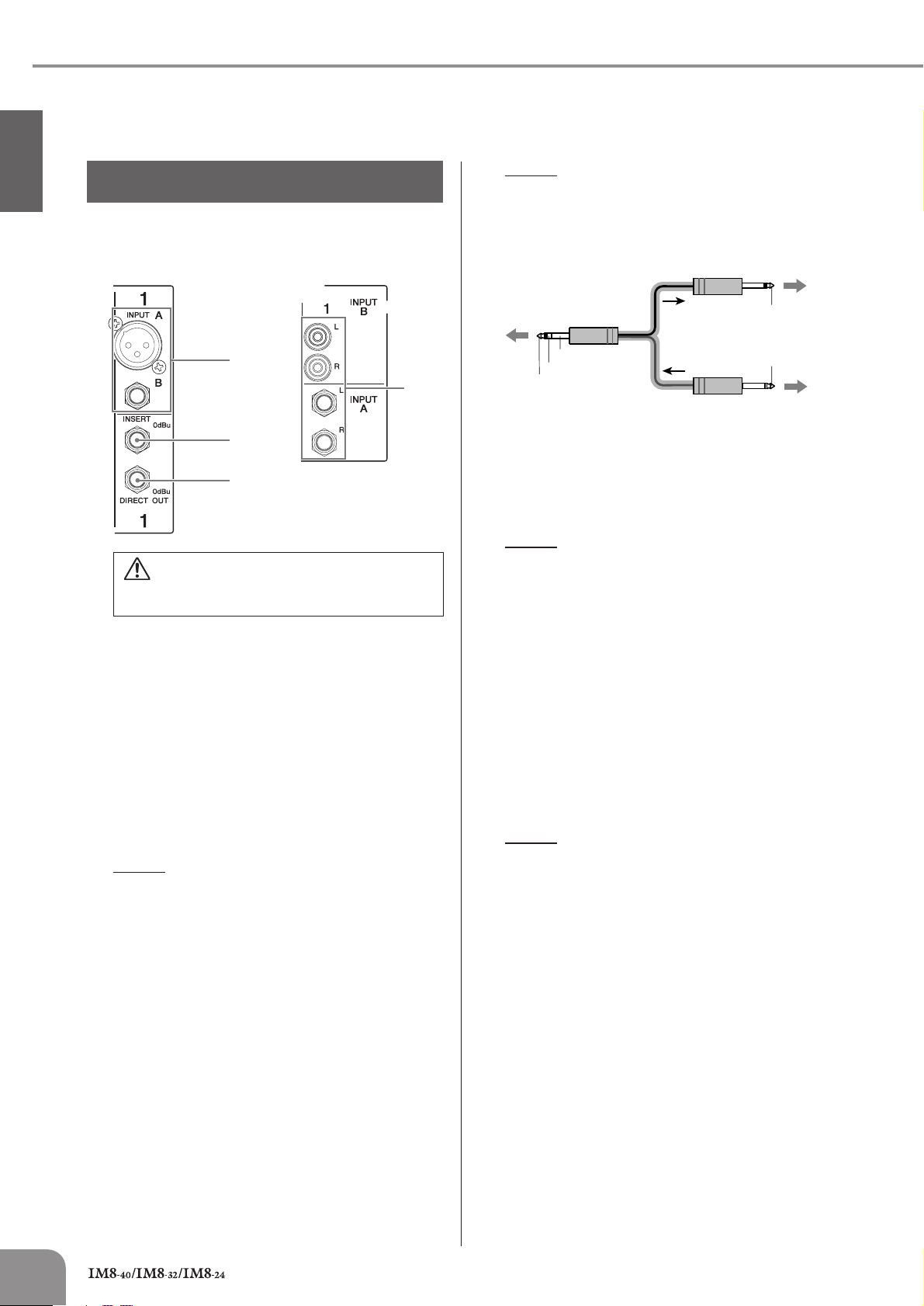
• Rear Panel
Monaural channels Stereo channels
NOTE
· Patching external devices via an INSERT jack requires a
special insert cable such as illustrated below (insert
cable sold separately).
To the input jack of the
external processor
1
2
3
Tu rn off the Yamaha PW8 power supply before you
connect or disconnect any cables to or from the
console.
INPUT Jack (monaural)
1
These monaural input jacks are used to connect microphones or musical instruments. Each input channel features two types of jacks (INPUT A and INPUT B).
• INPUT A Jack
These are balanced XLR-3-31 type input jacks (1:
Ground; 2: Hot; 3: Cold).
• INPUT B Jack
These are TRS phone-jack type balanced inputs. (T:
Hot; R; Cold; S: Ground)
You can connect either balanced or unbalanced phone
plugs to these jacks.
NOTE
· Only one type of jack can be used at a time on a single
channel.
4
To the INSERT jack
Sleeve (Ground)
Ring: IN
Tip: OUT
To the output jack of the
external processor
DIRECT OUT Jack
3
These are impedance balanced (page 19) phone-jack
type outputs. They output the signal that has passed
through the compressor.
NOTE
· If necessary, the signal that is output from the DIRECT
OUT jack can be changed to the signal immediately
before the channel fader (pre-fader) or the signal after
the channel fader (post-fader) by changing an internal
jumper. A fee will be charged for this modification. For
details, contact to your Yamaha dealer listed at the end of
this manual.
4
INPUT Jacks (stereo)
These are stereo input jacks that connect line-level
instruments, such as a synthesizer. Each input channel
features two types of jacks (INPUT A and INPUT B).
• INPUT A Jacks
These are unbalanced phone-jack stereo line inputs.
• INPUT B Jacks
These are unbalanced stereo RCA pin-jack line inputs.
NOTE
· Only one type of jack can be used at a time on a single
channel.
Tip: OUT
Tip: IN
2
INSERT Jack
These jacks are located between the compressor and
equalizer of the corresponding monaural input channel.
The INSERT jacks are ideal for connecting devices such
as graphic equalizers or noise filters into the corresponding channels. The INSERT jacks are TRS (tip,
ring, sleeve) phone jacks that carry both the send and
return signal (tip = send/out; ring = return/in; sleeve =
ground).
8
Owner’s Manual
Page 9
6
Controls and Functions
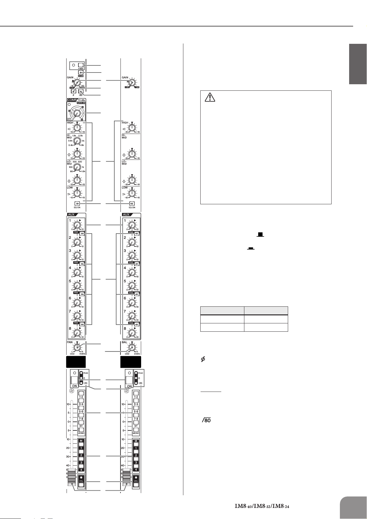
•Top Panel
Monaural channels Stereo channels
5
6
7
8
9
0
A
B
C
5
+48V Switch/Indicator
This switch toggles phantom power on and off for a
monaural channel. When the switch is turned on, the
+48V indicator will light, and DC +48V phantom power
will be supplied to Pin 2 and 3 of the corresponding
XLR-type INPUT A jacks. Turn this switch on when using
a phantom-powered condenser microphone.
• Be sure to leave this switch off if you do not need
phantom power.
•When turning phantom power on, be sure that only a
condenser microphone is connected to the INPUT A
jack of the monaural channel. Other devices may be
damaged if connected to phantom power. This precaution does not apply to balanced dynamic microphones,
however, as these will not be affected by phantom
power.
•To avoid damage to speakers, be sure to turn off
amplifiers (or powered speakers) before turning this
switch on or off. It’s also a good idea to turn the mixer’s
output controls - STEREO OUT master fader and
GROUP OUT faders - all the way down. If you omit this
precaution, you may damage your hearing or your
equipment.
6
26 dB (PAD) Switch
When this switch is turned on, the input signal from the
INPUT jack of the monaural channel is attenuated by 26
dB. Turn the switch off ( ) if you’ve connected a
microphone or other device with a low input level to the
channel. Turn it on ( ) if you’ve connected a line-level
device.
English
D
E
F
G
H
I
7
GAIN Control
This adjusts the sensitivity of the input signal from the
INPUT jack. Monaural channels have a 26 dB switch
) that lets you change the range of this control. The
(
adjustable sensitivity range is as follows.
• Monaural channel
26 dB switch Range
ON -34dB to +10dB
OFF -60dB to -16dB
• Stereo channel
-34dB to +10dB
8
(Phase) Switch
Turning this switch on will invert the phase of the input
signal. Turn this switch on if you need to mix a phasereversed signal.
NOTE
· If you try to mix a phase-reversed signal, the signals will
interfere with each other, resulting in degraded sound
quality.
9
(High Pass Filter) Switch
This switch toggles the HPF on or off.
Turning this switch ON will apply a high-pass filter that
attenuates the signal below 80 Hz by a slope of 12 dB/
octave.
J
K
L
Owner’s Manual
9
Page 10
Controls and Functions
10
English
COMP Control/Indicator
0
Adjusts the amount of compression applied to the channel. As the COMP knob is turned to the right the compression ratio increases while the output gain is
automatically adjusted accordingly. The result is
smoother, more even dynamics because louder signals
are attenuated while the overall level is boosted. The
COMP indicator will light when the compressor operates.
NOTE
·Avoid setting the compression too high, as the higher
average output level that results may lead to feedback.
A EQ (Equalizer): HIGH, HI-MID, LO-MID, LOW
This is a four-band equalizer, providing adjustments for
four frequency bands (HIGH, HI-MID, LO-MID, LOW).
Setting the gain control to the “▼” position produces a
flat response in the corresponding band. Turning the
gain control to the right boosts the corresponding frequency band, while turning to the left attenuates the
band. The HI-MID and LO-MID bands of monaural
channels provide a frequency control that lets you
adjust the center frequency.
The following table shows the EQ type, frequency, and
maximum cut/boost for each of the bands.
Monaural channel
Band Type Frequency
HIGH Shelving 10 kHz
HI-MID Peaking 400 Hz – 8 kHz
LO-MID Peaking 80 Hz – 1.6 kHz
LOW Shelving 100 Hz
Stereo channel
Band Type Frequency
HIGH Shelving 10 kHz
HI-MID Peaking 3 kHz
LO-MID Peaking 800 Hz
LOW Shelving 100 Hz
Maximum
Cut/Boost
±15 dB
Maximum
Cut/Boost
±15 dB
B EQ ON Switch
Switches the equalizer on or off.
C AUX Controls (1–8)
These adjust the level of the signals sent from the input
channel to AUX buses 1–8. These knobs should generally be set close to the “▼” (nominal) position. The signal adjusted by these controls is determined by the PRE
switch (D).
D PRE Switches
For each two buses, these switches select whether the
signal sent to the AUX buses will be taken after the
equalizer and before the channel fader (pre-fader), or
after the channel fader (post-fader). If this switch is ON,
the pre-fader signal is sent to the AUX bus, and will not
be affected by the channel fader.
NOTE
· If necessary, the pre-fader signal sent to the AUX buses
can be changed to the signal before the equalizer by
changing an internal jumper. A fee will be charged for
this modification. In this case, the signal will be sent to
the AUX buses even if the input channel’s ON switch is
turned off. For details, contact to your Yamaha dealer
listed at the end of this manual.
E PAN Control
This control determines the stereo positioning of the
monaural channel signal on the buses.
Rotate the knob clockwise to pan the signal to the odd
channels of the GROUP buses and the ST L bus, and
counter-clockwise to pan the signal to the even channels of the GROUP buses and the ST R bus.
F BAL Control
Adjusts the left and right volume balance of stereo
channels. The signal input to the INPUT L jack will be
sent to the odd channels of the GROUP buses or to the
ST L bus, and the signal input to the INPUT R jack will
be sent to the even channels of the GROUP buses or to
the ST R bus.
G ON Switch/Indicator
When this switch is on, that channel will be enabled and
the indicator will light.
NOTE
· Even if the ON switch is off, you can turn on the PFL
switch (K) and monitor the signal before the channel
fader via the MONITOR OUT jacks and the PHONES
jack.
H Input Meter
Three LEDs indicate the input channel signal level after
the equalizer. The “-20” LED will light if the input signal
level reaches -20 dB, and the “0” LED will light at nominal level. The PEAK LED will light red when the input signal reaches 3 dB before clipping.
I Bus Assign Switches
These switches determine the bus(es) to which each
channel’s signal is sent. Turning a switch on will output
the signal to the corresponding bus.
• 1-2, 3-4, 5-6, 7-8 switches: Assign the channel’s
signal to the GROUP 1/2–7/8 buses.
• ST switch: Assigns the channel’s signal to the Stereo
L and R buses.
• MONO switch: Assigns the channel’s signal to the
MONO bus.
NOTE
· If you want the signal to be output to the corresponding
bus(es), turn on the channel ON switch (G).
J MUTE Switches (1–4)
These assign the channel’s mute on/off to switches 1–4.
If you turn on the MUTE master switches (1–4)
(page 15) located in the MUTE MASTER section, the
input channels whose corresponding MUTE switch is on
will be muted.
NOTE
·When a channel is muted, the ON indicator (G) will go
dark.
· Even if a channel is muted, you can turn on the PFL
switch (K) and monitor the signal before the channel
fader via the MONITOR OUT jacks and the PHONES
jack.
Owner’s Manual
Page 11

K PFL Switch/Indicator
When the PFL switch is on, the indicator will light and
the channel pre-fader signal is output to the PHONES
and MONITOR OUT jacks for monitoring.
NOTE
·When you turn on the PFL switch, the PFL indicator of the
MONITOR section (page 18) will light.
L Channel Fader
Adjusts the output level of the input channel signal. Use
these faders to adjust the balance between the various
channels.
NOTE
·To minimize noise, the faders of unused channels should
be set to the lowest position.
· The channel faders will affect the ST, MONO, GROUP 1–
8, and AUX 1–8 (when the PRE switch is off) buses.
Controls and Functions
English
Owner’s Manual
11
Page 12

Controls and Functions
Master Control Section
English
Rear Panel
MONITOR Section (page 18)
STEREO MASTER Section
(page 17)
MATRIX OUT Section (page 14)
2TR IN/USB Section (page 13)
Top Panel
2TR IN/USB Section (page 13)
REC OUT/USB Section (page 14)
TALKBACK Section (page 15)
MONO Section (page 19) AUX SEND Section
(page 16)
REC OUT/USB Section (page 14)
MATRIX OUT Section (page 14)
STEREO AUX RETURN
Section (page 13)
GROUP OUT Section
(page 16)
DC POWER INPUT
DC POWER INPUT
Section (page 15)
DC POWER INPUT Section
(page 15)
MUTE MASTER Section
(page 15)
STEREO MASTER Section
(page 17)
AUX SEND Section (page 16)
GROUP OUT Section (page 16)
TALKBACK Section (page 15)
MONITOR Section (page 18)
MONO Section (page 19)
12
STEREO MASTER Section (page 17)
Owner’s Manual
Page 13

Controls and Functions
STEREO AUX RETURN Section
Rear Panel Top Panel
1
2
3
4
5
AUX RETURN Jacks
1
These are unbalanced phone-jack type line inputs. Signals input from these jacks can be sent to the GROUP 1/
2–7/8, ST L/R, MONO, and AUX 1–4 buses. To the
MONO and AUX 1–4 buses, a mix of the L/MONO and R
signal is sent. These jacks are typically used to receive
the signal returned from an external effect device
(reverb, delay, etc.).
NOTE
· These jacks can also be used as auxiliary stereo inputs.
· If you connect to the L/MONO jack only, the mixer will
recognize the signal as monaural and will send the identical signal to both the L/MONO and R jacks.
2 AUX Controls (1–4)
These adjust the level at which the signals from the AUX
RETURN jacks are sent (with L and R mixed) to the AUX
1–4 buses.
The “▼” position of the knob is nominal level (0 dB).
3 Bus Assign Switches
These switches determine the bus(es) to which the signal is received from the AUX RETURN jacks.
• 1-2, 3-4, 5-6, 7-8 switches: Send the signal to the
GROUP 1/2–7/8 buses.
• ST switch: Sends the signal to the ST L/R bus.
• MONO switch: Sends the signal to the MONO bus.
4 RETURN Control
Adjusts the level of the signal sent from the AUX
RETURN jacks to the GROUP 1/2–7/8, ST L/R, or MONO
buses.
The “▼” position of the knob is nominal level (0 dB).
NOTE
· The signals sent to AUX 1–4 are not affected by the
RETURN control.
5 PFL Switch/Indicator
When the PFL switch is on, the indicator will light and
the signal before the AUX controls and RETURN control
in the STEREO AUX RETURN section is output to the
MONITOR OUT and PHONES jacks for monitoring.
NOTE
·When you turn on the PFL switch, the PFL indicator in the
MONITOR section (page 18) will light.
2TR IN/USB Section
Rear Panel
Top Panel
1
2TR IN Jacks
These are RCA pin jacks and a mini-phone jack (stereo)
for inputting a stereo audio source. Use these jacks
when you want to connect a CD player, and output the
signal to the ST L/R or MONO bus.
NOTE
· If signals are simultaneously input from the 2TR IN jacks
(RCA pin jacks, mini-phone jack) and the USB connector,
the signals will be mixed.
Front Panel
1
2
3
4
5
2 USB Connector
Connects to the computer via the included cable to
input and output the signals. This connector outputs the
same signal as the REC OUT jacks. The signal input
from this connector is sent to the ST L/R bus or the
MONO bus.
When connecting or disconnecting the USB cable
be sure to turn the 2TR IN/USB control all the way
down.
Precautions when using the USB connector
When connecting the computer to the USB connector,
make sure to observe the following points. Failing to do
so risks freezing the computer and corrupting or losing
English
Owner’s Manual
13
Page 14

Controls and Functions
English
the data. If the computer or the instrument freezes,
restart the application software or the computer OS, or
turn the power to the instrument off then on again.
• Use an AB type USB cable of less than about 3
meters.
•To prevent loud pops and noises, turn on the power to
your equipment in the following order; first the audio
sources, then the PW8, and finally the power amplifiers. Reverse this order when turning the power off.
• Before connecting the computer to the USB connector,
exit from any power-saving mode of the computer
(such as suspended, sleep, standby).
• Before turning on the power to the instrument, connect
the computer to the USB connector.
•Execute the following before turning the power to the
instrument on/off or plugging/unplugging the USB
cable to/from the USB connector.
- Quit any open application software on the computer.
-Make sure that data is not being transmitted from
the instrument.
•While the computer is connected to the instrument,
you should wait for six seconds or more between
these operations: (1) when turning the power of the
instrument off then on again, or (2) when alternately
connecting/disconnecting the USB cable.
2 Bus Assign Switches
These switches determine the signal sent to the REC
OUT jacks and USB connector. If you’re sending the
signal of the MONO bus, the same signal will be output
to the L and R of the REC OUT jacks and the USB connector.
• ST switch: The signal of the ST L/R bus will be
output from the REC OUT jacks and the USB
connector.
• MONO switch: The signal of the MONO bus will be
output from the REC OUT jacks and the USB
connector.
NOTE
· If both the ST switch and the MONO switch are on, the
mixed signals of the ST L/R bus and MONO bus will be
output.
MATRIX OUT Section
Rear Panel Top Panel
1
3 Bus Assign Switches
These switches determine the bus(es) to which the signal received from the 2TR IN jacks and the USB connector is sent.
• ST switch: Sends the signal to the ST L/R bus.
• MONO switch: Sends the mixed L and R signal to
the MONO bus.
4 2TR IN/USB Control
Adjusts the level of the signal received from the 2TR IN
jacks and the USB connector.
5 PFL Switch/Indicator
When the PFL switch is on, the indicator will light and the
signal before the 2TR IN/USB control is output to the MONITOR OUT and PHONES jacks for monitoring.
NOTE
·When you turn on the PFL switch, the PFL indicator of the
MONITOR section (page 18) will light.
REC OUT/USB Section
Rear Panel Top Panel
1
2
3
4
5
6
14
2
1 REC OUT Jacks
These RCA pin jacks can be connected to an external
recorder such as an MD recorder in order to record the
signal of the ST L/R bus or MONO bus.
NOTE
· The STEREO OUT master fader and MONO fader has no
affect on the signal via these jacks.
Owner’s Manual
1
MATRIX OUT Jack
This is an impedance balanced (page 19) TRS phonejack type output. This jack outputs the signal adjusted
by the controls in the MATRIX OUT section.
2 GROUP Controls (1–8)
These adjust the level of the signals sent from GROUP
OUT 1–8 to the MATRIX OUT jacks.
3 ST Controls (L, R)
These adjust the level of the signals sent from ST OUT L/
R to the MATRIX OUT jacks.
Page 15

Controls and Functions
4 MONO Control
This control adjusts the level of the signal sent from
MONO OUT to the MATRIX OUT jacks.
5 MATRIX master Control
This control adjusts the overall level of the signal output
to the MATRIX OUT jacks. The “▼” position of the knob
is nominal level (0 dB).
6 AFL Switch/Indicator
When the AFL switch is on, the indicator will light and
the signal after the MATRIX master control is output to
the PHONES and MONITOR OUT jacks for monitoring.
NOTE
· If you want to monitor the signal after the MATRIX master
control, turn off all PFL switches.
DC POWER INPUT Section
Rear Panel Top Panel
PUT
1
2
TALKBACK Section
Rear Panel Top Panel
1
2
3
4
1
TALKBACK MIC IN Jack
This is an XLR-3-31 type unbalanced input jack for connecting a talkback microphone.
English
DC POWER INPUT Connector
1
Connects the Yamaha Power Supply PW8 to the console
using the included power supply cable.
•Turn off the Yamaha PW8 power supply before you
connect or disconnect the power supply cable to or
from the console.
•To prevent loud pops and noises, turn on the power to
your equipment in the following order; first the audio
sources, then the PW8, and finally the power amplifiers. Reverse this order when turning the power off.
2 POWER Indicator
This will light when the Yamaha PW8 power supply is
connected to the console and the PW8 is turned on.
MUTE MASTER Section
Top Panel
2 Bus Assign Switches
These determine the output destination of the signal
from the TALKBACK MIC jack.
• AUX 1-2, 3-4, 5-6, 7-8 switches: Send the signal to
the AUX 1/2–7/8 buses.
• GROUP 1-8 switch: Sends the signal to the GROUP
1–8 buses.
• STEREO/MONO switch: Sends the signal to the ST
L/R and MONO buses.
• MATRIX 1-2, 3-4 switches: Send the signal to the
MATRIX 1/2 or 3/4 buses.
3 TALKBACK LEVEL Control
Adjusts the level of the signal received from the TALKBACK MIC jack.
4 ON Switch/Indicator
When you turn this switch on, the indicator will flash and
the talkback function will be enabled.
1
MUTE Master Switches/Indicators (1–4)
1
These switches toggle input channel muting on and off.
Turning a switch (1–4) on will mute the input channels
whose MUTE switch (page 10) of the corresponding
number is turned on. When the signal is muted, the ON
indicator of the input channels will go dark.
Owner’s Manual
15
Page 16

Controls and Functions
English
AUX SEND Section
Rear Panel Top Panel
1
2
3
4
5
1 AUX INSERT Jack
This is an input/output jack located before the AUX
SEND fader. You can connect a graphic equalizer or
other signal processor. This is a TRS (tip, ring, sleeve)
phone jack that carries both the send and return signal
(tip = send/out; ring = return/in; sleeve = ground).
NOTE
· Patching external devices via an INSERT jack requires a
special insert cable such as illustrated below (insert
cable sold separately).
4 AUX SEND Fader
Controls the level of the signal output to the AUX SEND
jack.
5 AFL Switch/Indicator
When the AFL switch is on, the indicator will light and
the signal after the AUX SEND fader is output to the
MONITOR OUT and PHONES jacks for monitoring.
NOTE
· If you want to monitor the signal after the AUX SEND
fader, turn off all PFL switches.
GROUP OUT Section
Rear Panel Top Panel
1
2
4
3
5
To the input jack of the
external processor
To the INSERT jack
Sleeve (Ground)
Ring: IN
Tip: OUT
To the output jack of the
external processor
Tip: OUT
Tip: IN
2 AUX SEND Jacks
These are balanced XLR-3-32 type output jacks (1:
Ground; 2: Hot; 3: Cold). You can use these jacks, for
example, to connect to a monitor system or an external
effect unit.
3 AUX SEND Meter
Three LEDs indicate the signal level after the AUX SEND
fader.
The “-20” LED will light if the output signal level reaches
-20 dB, and the “0” LED will light at nominal level. The
PEAK LED will light red when the output signal reaches
3 dB before clipping.
8
1
GROUP INSERT Jack
This is an input/output jack located before the GROUP
OUT fader. You can connect a graphic equalizer or
other signal processor. This is a TRS (tip, ring, sleeve)
phone jack that carries both the send and return signal
(tip = send/out; ring = return/in; sleeve = ground).
NOTE
· Patching external devices via an INSERT jack requires a
special insert cable such as illustrated below (insert
cable sold separately).
To the input jack of the
external processor
6
7
16
Owner’s Manual
To the INSERT jack
Sleeve (Ground)
Ring: IN
Tip: OUT
Tip: OUT
Tip: IN
To the output jack of the
external processor
Page 17

Controls and Functions
2 GROUP OUT Jacks
These are TRS phone type impedance-balanced
(page 19) output jacks that output the GROUP OUT signals. You can connect these jacks to a multi-track
recorder, external mixer, or other such device.
3 PAN Controls
These adjust the stereo position of the signals sent from
GROUP OUT to the ST L/R bus. Rotate the knob clockwise to pan the signal right, and counter-clockwise to
pan left.
4 ON Switch/Indicator
When this switch is on, that GROUP OUT will be
enabled and the indicator will light.
5 GROUP OUT Meter
Three LEDs indicate the signal level after the GROUP
OUT fader.
The “-20” LED will light if the output signal level reaches
-20 dB, and the “0” LED will light at nominal level. The
PEAK LED will light red when the GROUP OUT signal
reaches 3 dB before clipping.
6 Bus Assign Switches
These switches assign the GROUP OUT signal to the ST
L/R bus and the MONO bus.
NOTE
·Turn the ON switch on if you want to send the GROUP
OUT signal to the ST L/R bus or MONO bus.
STEREO MASTER Section
Rear Panel Top Panel
1
2
3
4
English
7 AFL Switch/Indicator
When the AFL switch is on, the indicator will light and
the signal after the GROUP OUT fader but before the
ON switch is output to the MONITOR OUT and PHONES
jacks for monitoring.
NOTE
· If you want to monitor the signal after the GROUP OUT
fader, turn off all PFL switches.
8 GROUP OUT Fader
Controls the level of the GROUP OUT signal.
5
6
7
1
STEREO INSERT Jack
This is an input/output jack located before the STEREO
OUT master fader. You can connect a graphic equalizer
or other signal processor. This is a TRS (tip, ring, sleeve)
phone jack that carries both the send and return signal
(tip = send/out; ring = return/in; sleeve = ground).
Owner’s Manual
17
Page 18

Controls and Functions
English
NOTE
· Patching external devices via an INSERT jack requires a
special insert cable such as illustrated below (insert
cable sold separately).
To the input jack of the
external processor
To the INSERT jack
Sleeve (Ground)
Ring: IN
Tip: OUT
To the output jack of the
external processor
Tip: OUT
Tip: IN
2 STEREO OUT Jacks
These are XLR-3-32 type balanced output jacks that
output the mixed stereo signal. They output the signal
adjusted by the STEREO OUT master faders (7). Connect these jacks to the power amplifiers that drive your
main speakers.
3 STEREO Level Meter
These LEDs indicate the level of the signal sent to the
STEREO OUT jacks.
The “0” segment indicates the nominal output level. The
PEAK segment lights red when the output approaches
the clipping level.
4 ON Switch/Indicator
When this switch is on, ST OUT will be enabled and the
indicator will light.
5 PFL Switch/Indicator
When the PFL switch is on, the indicator will light and
the signal before the STEREO OUT master fader is output to the MONITOR OUT and PHONES jacks for monitoring.
6 AFL Switch/Indicator
When the AFL switch is on, the indicator will light and
the signal after the STEREO OUT master faders is output to the PHONES and MONITOR OUT jacks for monitoring.
NOTE
· If you want to monitor the signal after the STEREO OUT
master faders, turn off all PFL switches.
7 STEREO OUT Master Faders
These adjust the signal level sent to the STEREO OUT
jacks.
MONITOR Section
Rear Panel Top Panel
1
Front Panel
2
3
4
5
6
MONITOR OUT Jacks
1
These are impedance-balanced (page 19) TRS phonetype output jacks that you can connect to your monitor
system. These jacks output the signal before or after the
faders for the various buses. The PFL/AFL indicator (4)
and the PFL and AFL indicators in each section indicate
which signal is being output.
NOTE
· If both a PFL switch and AFL switch are on, the PFL
switch will be enabled. If you want to monitor the signals
after the faders, turn off all PFL switches.
2 PHONES Jack
Connects a pair of headphones to this stereo phonetype output jack. These jacks output the signal before or
after the faders for the various buses.
3 MONITOR Level Meter
Indicates the level of the signal output to the MONITOR
OUT and PHONES jacks.
The “0” segment indicates the nominal output level. The
PEAK segment lights red when the output approaches
the clipping level.
4 PFL/AFL Indicator
Indicates the signal sent to the MONITOR OUT and
PHONES jacks. The PFL indicator will light when the signals before the faders (control) are being sent; the AFL
indicator will light if the signals after the faders are being
sent.
18
5 MONITOR Control
Controls the level of the signal output to the MONITOR
OUT jacks.
6 PHONES Control
Controls the level of the signal output to the PHONES
jack.
Owner’s Manual
Page 19

Controls and Functions
MONO Section
Rear Panel Top Panel
1
2
3
6
4
5
4 MONO Level Meter
Three LEDs indicate the signal level after the MONO
fader. The “-20” LED will light if the output signal level
reaches -20 dB, and the “0” LED will light at nominal
level. The PEAK LED will light red when the MONO OUT
signal reaches 3 dB before clipping.
5 AFL Switch/Indicator
When the AFL switch is on, the indicator will light and
the signal after the MONO fader is output to the MONITOR OUT and PHONES jacks for monitoring.
NOTE
· If you want to monitor the signal after the MONO fader,
turn off all PFL switches.
6 MONO Fader
Controls the level of the signal output to the MONO jack.
LAMP Connector
This is an XLR-4-31 type connector that supplies power to a
separately sold gooseneck lamp (e.g., Yamaha LA5000).
The IM8-40 mixer has three of these connectors, and the
IM8-32/24 mixers have two.
English
MONO INSERT Jack
1
This is an input/output jack located before the MONO
fader.
You can connect a graphic equalizer or other signal processor. This is a TRS (tip, ring, sleeve) phone jack that
carries both the send and return signal (tip = send/out;
ring = return/in; sleeve = ground).
NOTE
· Patching external devices via an INSERT jack requires a
special insert cable such as illustrated below (insert
cable sold separately).
To the input jack of the
external processor
To the INSERT jack
Sleeve (Ground)
Ring: IN
Tip: OUT
To the output jack of the
external processor
Tip: OUT
Tip: IN
2 MONO OUT Jack
This is an XLR-3-32 type balanced output jack that outputs the MONO OUT signal.
3 ON Switch/Indicator
When this switch is on, the MONO OUT will be enabled
and the indicator will light.
Impedance balanced:
Since the hot and cold terminals of impedance balanced
output jacks have the same output impedance, these output jacks are less affected by induced noise.
Owner’s Manual
19
Page 20

Troubleshooting
Troubleshooting
Power doesn’t come on.
English
• Is the dedicated PW8 power supply properly plugged into
• Is the dedicated PW8 power supply properly connected
• If the above checks do not identify the problem, call
The sound of the bass drum will not move forward in
the mix.
• Could you be mixing a phase-reversed signal?
How can I send the pre-EQ signal to an AUX bus for
monitoring?
• You can send the pre-EQ signal to an AUX bus by
an appropriate AC power outlet?
using the included power supply cable?
The PW8 itself will not power-on unless it is correctly connected via the included power cable.
Yamaha for service.
Try turning on the switch to reverse the phase. If you
are capturing the sound using multiple mics, phase reversal may be causing cancellation.
changing an internal jumper setting. Turn the AUX PRE
switch on (pre-fader). In this case, the signal will be sent
to the AUX bus even if the input channel’s ON switch is
off.
How can I monitor the signal of a GROUP bus before I
send it to the ST L/R bus?
• With the GROUP section ON switch turned off, turning the
GROUP section AFL switch on will let you monitor the AFL
signal of the GROUP bus without sending it to the ST L/R
(and MONO) bus.
How can I send a compressed signal to the ST L/R
bus while sending the uncompressed signal to
DIRECT OUT jacks for recording?
• If you connect a compressor (external device) to the
INSERT jacks and apply compression to the signal being
sent to the ST L/R bus, the signal before the compressor
will be sent to the DIRECT OUT jacks. In this case, turn off
the IM8’s COMP control.
How can I send the TALKBACK signal only to the
intercom?
• In the TALKBACK section, turn on only MATRIX 1-2 (or
MATRIX 3-4) to send the output of MATRIX 1-2 (or
MATRIX 3-4) to the intercom.
How can I play background music from a portable
audio player?
•A standard mini-phone type 2TR IN jack is provided on
the front panel, allowing you to connect your portable
audio player via a mini-plug cable.
20
How can I assign the MC to the MONO bus and also
record it?
• Assign the MC’s input channel to the MONO bus, and use
the REC OUT section bus assign switch to select the
MONO bus.
Owner’s Manual
Page 21

About the accessory disk
About the accessory disk
SPECIAL NOTICE
The software included in the accessory disk and the copyrights thereof are under exclusive ownership by Steinberg
Media Technologies GmbH.
Use of the software and this manual is governed by the license agreement which the purchaser fully agrees to upon
breaking the seal of the software packaging. (Please read carefully the Software Licensing Agreement at the end of this
manual before installing the application.)
Copying of the software or reproduction of this manual in whole or in part by any means is expressly forbidden without
the written consent of the manufacturer.
Yamaha makes no representations or warranties with regard to the use of the software and documentation and cannot be
held responsible for the results of the use of this manual and the software.
This disk is NOT for audio/visual purpose. Do not attempt to play the disk on an audio/visual CD/DVD player. Doing so
may result in irreparable damage to your player.
For information about the minimum system requirements and latest information of the software in the disk, check the web
site below.
<http://www.yamahasynth.com/>
Note that Yamaha does not offer technical support for the DAW software in the accessory disk.
About the DAW software in the accessory disk
The accessory disk contains DAW software both for Windows and Macintosh.
NOTE
·Make sure to install DAW software under the “Administrator” account.
· In order to have continuous use of the DAW software in the accessory disk, including support and other benefits, you will need to register the software and activate your software license by starting it while the computer is connected to the Internet. Click the "Register
Now" button shown when the software is started, then fill in all required fields for registration. If you do not register the software, you
will be unable to use it after a limited period of time expires.
· If you are using a Macintosh computer, double-click the “***.mpkg” file to start installation.
For information about the minimum system requirements and latest information on the software in the disk, check the
web site below.
<http://www.yamahasynth.com/>
English
About software support
Support for the DAW software in the accessory disk is provided by Steinberg on its website at the following address.
http://www.steinberg.net
You can visit the Steinberg site also via the Help menu of the included DAW software. (The Help menu also includes the
PDF manual and other information on the software.)
Owner’s Manual
21
Page 22

About the accessory disk
ATTENTION
SOFTWARE LICENSE AGREEMENT
English
PLEASE READ THIS SOFTWARE LICENSE AGREEMENT (“AGREEMENT”) CAREFULLY BEFORE USING THIS SOFTWARE. YOU ARE ONLY
PERMITTED TO USE THIS SOFTWARE PURSUANT TO THE TERMS AND CONDITIONS OF THIS AGREEMENT. THIS AGREEMENT IS BETWEEN
YOU (AS AN INDIVIDUAL OR LEGAL ENTITY) AND YAMAHA CORPORATION (“YAMAHA”).
BY BREAKING THE SEAL OF THIS PACKAGE YOU ARE AGREEING TO BE BOUND BY THE TERMS OF THIS LICENSE. IF YOU DO NOT AGREE
WITH THE TERMS, DO NOT INSTALL, COPY, OR OTHERWISE USE THIS SOFTWARE.
THIS AGREEMENT PROVIDES YOUR USE-CONDITIONS ABOUT THE “DAW” SOFTWARE OF STEINBERG MEDIA TECHNOLOGIES
GMBH(“STEINBERG”) WHICH IS BUNDLED WITH THIS PRODUCT. SINCE THE END-USER SOFTWARE LICENSE AGREEMENT (EUSLA)
SHOWN ON YOUR PC-DISPLAY IN YOUR INSTALLING THE “DAW” SOFTWARE IS REPLACED BY THIS AGREEMENT, YOU SHOULD DISREGARD THE EUSLA. THAT IS, IN THE INSTALLING PROCESS, YOU SHOULD SELECT “AGREE” WITH THE EUSLA, WITHOUT YOUR JUDGMENT
THERETO, SO AS TO PROCEED TO THE NEXT PAGE.
1. GRANT OF LICENSE AND COPYRIGHT
Yamaha hereby grants you the right to use one copy of the software
program(s) and data (“SOFTWARE”) accompanying this Agreement.
The term SOFTWARE shall encompass any updates to the accompanying software and data. The SOFTWARE is owned by STEINBERG,
and is protected by relevant copyright laws and all applicable treaty
provisions. Yamaha has acquired the sublicense right to license you
to use the SOFTWARE. While you are entitled to claim ownership of
the data created with the use of SOFTWARE, the SOFTWARE will
continue to be protected under relevant copyrights.
· You may use the SOFTWARE on a single computer.
· You may make one copy of the SOFTWARE in machine-readable
form for backup purposes only, if the SOFTWARE is on media
where such backup copy is permitted. On the backup copy, you
must reproduce Yamaha’s copyright notice and any other proprietary legends that were on the original copy of the SOFTWARE.
· You may permanently transfer to a third party all your rights in the
SOFTWARE only when you transfer this product together, provided
that you do not retain any copies and the recipient reads and
agrees to the terms of this Agreement.
2. RESTRICTIONS
· You may not engage in reverse engineering, disassembly, decom-
pilation or otherwise deriving a source code form of the SOFTWARE by any method whatsoever.
· You may not reproduce, modify, change, rent, lease, or distribute
the SOFTWARE in whole or in part, or create derivative works of the
SOFTWARE.
· You may not electronically transmit the SOFTWARE from one com-
puter to another or share the SOFTWARE in a network with other
computers.
· You may not use the SOFTWARE to distribute illegal data or data
that violates public policy.
· You may not initiate services based on the use of the SOFTWARE
without permission by Yamaha Corporation.
Copyrighted data, including but not limited to MIDI data for songs,
obtained by means of the SOFTWARE, are subject to the following
restrictions which you must observe.
· Data received by means of the SOFTWARE may not be used for
any commercial purposes without permission of the copyright
owner.
· Data received by means of the SOFTWARE may not be duplicated,
transferred, or distributed, or played back or performed for listeners in public without permission of the copyright owner.
· The encryption of data received by means of the SOFTWARE may
not be removed nor may the electronic watermark be modified
without permission of the copyright owner.
3. TERMINATION
This Agreement becomes effective on the day that you receive the
SOFTWARE and remains effective until terminated. If any copyright
law or provisions of this Agreement is violated, the Agreement shall
terminate automatically and immediately without notice from
Yamaha. Upon such termination, you must immediately destroy the
licensed SOFTWARE, any accompanying written documents and all
copies thereof.
4. LIMITED WARRANTY ON MEDIA
As to SOFTWARE sold on tangible media, Yamaha warrants that the
tangible media on which the SOFTWARE is recorded will be free from
defects in materials and workmanship under normal use for a period
of fourteen (14) days from the date of receipt, as evidenced by a
copy of the receipt. Yamaha’s entire liability and your exclusive remedy will be replacement of the defective media if it is returned to
Yamaha or an authorized Yamaha dealer within fourteen days with a
copy of the receipt. Yamaha is not responsible for replacing media
damaged by accident, abuse or misapplication. TO THE FULLEST
EXTENT PERMITTED BY LAW, YAMAHA EXPRESSLY DISCLAIMS
ANY IMPLIED WARRANTIES ON THE TANGIBLE MEDIA, INCLUDING THE IMPLIED WARRANTIES OF MERCHANTABILITY AND FITNESS FOR A PARTICULAR PURPOSE.
5. DISCLAIMER OF WARRANTY ON SOFTWARE
You expressly acknowledge and agree that use of the SOFTWARE is
at your sole risk. The SOFTWARE and related documentation are
provided “AS IS” and without warranty of any kind. NOTWITHSTANDING ANY OTHER PROVISION OF THIS AGREEMENT, YAMAHA
EXPRESSLY DISCLAIMS ALL WARRANTIES AS TO THE SOFTWARE,
EXPRESS, AND IMPLIED, INCLUDING BUT NOT LIMITED TO THE
IMPLIED WARRANTIES OF MERCHANTABILITY, FITNESS FOR A
PAR TICULAR PURPOSE AND NON-INFRINGEMENT OF THIRD
PAR TY RIGHTS. SPECIFICALLY, BUT WITHOUT LIMITING THE
FOREGOING, YAMAHA DOES NOT WARRANT THAT THE SOFTWARE WILL MEET YOUR REQUIREMENTS, THAT THE OPERATION
OF THE SOFTWARE WILL BE UNINTERRUPTED OR ERROR-FREE,
OR THAT DEFECTS IN THE SOFTWARE WILL BE CORRECTED.
6. LIMITATION OF LIABILITY
YAMAHA’S ENTIRE OBLIGATION HEREUNDER SHALL BE TO PERMIT USE OF THE SOFTWARE UNDER THE TERMS HEREOF. IN NO
EVENT SHALL YAMAHA BE LIABLE TO YOU OR ANY OTHER PERSON FOR ANY DAMAGES, INCLUDING, WITHOUT LIMITATION,
ANY DIRECT, INDIRECT, INCIDENTAL OR CONSEQUENTIAL DAMAGES, EXPENSES, LOST PROFITS, LOST DATA OR OTHER DAMAGES ARISING OUT OF THE USE, MISUSE OR INABILITY TO USE
THE SOFTWARE, EVEN IF YAMAHA OR AN AUTHORIZED DEALER
HAS BEEN ADVISED OF THE POSSIBILITY OF SUCH DAMAGES. In
no event shall Yamaha’s total liability to you for all damages, losses
and causes of action (whether in contract, tort or otherwise) exceed
the amount paid for the SOFTWARE.
7. GENERAL
This Agreement shall be interpreted according to and governed by
Japanese law without reference to principles of conflict of laws. Any
dispute or procedure shall be heard before the Tokyo District Court in
Japan. If for any reason a court of competent jurisdiction finds any
portion of this Agreement to be unenforceable, the remainder of this
Agreement shall continue in full force and effect.
8. COMPLETE AGREEMENT
This Agreement constitutes the entire agreement between the parties
with respect to use of the SOFTWARE and any accompanying written
materials and supersedes all prior or contemporaneous understandings or agreements, written or oral, regarding the subject matter of
this Agreement. No amendment or revision of this Agreement will be
binding unless in writing and signed by a fully authorized representative of Yamaha.
22
Owner’s Manual
Page 23

English
Owner’s Manual
23
Page 24

Specifications
Specifications
EnglishItaliano Español Français Deutsch
Electrical Specifications
MIN TYP MAX UNIT
Frequency Response STEREO OUT
Total Harmonic Distortion (THD + N)
Hum & Noise
Hum & Noise are measured with a 6 dB/
octave filter @ 12.7 kHz; equivalent to a
20 kHz filter with infinite dB/octave
attenuation.
Crosstalk (1 kHz) Adjacent Input MONO CH INPUT*, GAIN: min -70 dB
Maximum Voltage Gain (1 kHz)
All faders and controls are maximum
when measured.
PAN/BAL: panned hard left or hard right.
GROUP OUT
AUX SEND
MONITOR OUT
REC OUT
STEREO OUT +14 dBu @ 20 Hz-20 kHz, GAIN: min 0.1 %
MONO CH INPUT* EIN (Equivalent Input Noise) Rs = 150 Ω, GAIN: max -128 dBu
STEREO OUT
GROUP OUT
AUX SEND AUX SEND faders at nominal level and all CH AUX controls at
STEREO OUT
GROUP OUT
STEREO OUT Residual output noise -98 dBu
Input to Output STEREO OUT L/R, MOMO CH INPUT*, PAN: panned hard left or right -70 dB
Rs = 150 Ω
INPUT GAIN: max
From MONO CH
INPUT*
Rs = 150 Ω
INPUT GAIN: max
From ST CH
INPUT 1-4
From AUX
RETURN
From 2TR IN STEREO OUT 27.8 dB
From TALKBACK
MIC IN
GAIN: min (MONO CH INPUT*, ST CH INPUT 1-4)
20 Hz-20 kHz
Nominal output level @ 1 kHz
Input: MONO CHs*, ST CHs 1-4, AUX RETURN, 2TR IN
STEREO OUT, GROUP OUT faders at nominal level and all CH assign
switches off.
minimum.
STEREO OUT, GROUP OUT faders and one CH fader at nominal level.
INSERT OUT (MONO CH) 60 dB
DIRECT OUT (MONO CH) 60 dB
INSERT OUT (STEREO, GROUP, MONO) 70 dB
STEREO OUT
GROUP OUT
MATRIX OUT 90 dB
REC OUT 62.2 dB
MONO OUT 84 dB
MONITOR OUT 70 dB
PHONES OUT 79 dB
AUX SEND, PRE 80 dB
AUX SEND, POST 90 dB
INSERT OUT (AUX), PRE 66 dB
INSERT OUT (AUX), POST 76 dB
STEREO OUT
GROUP OUT
AUX SEND, PRE 51 dB
AUX SEND, POST 61 dB
STEREO OUT
GROUP OUT
AUX SEND 13 dB
STEREO OUT
AUX OUT
-3.0 0.0 1.0 dB
-80 dBu
-75 dBu
-64 dBu
84 dB
58 dB
16 dB
70 dBGROUP OUT
166
All faders are nominal when measured. (The nominal position is 10 dB lower than the maximum position.)
Output impedance of signal generator: 150 ohms
* IM8-40: 1-40, IM8-32: 1-32, IM8-24: 1-24
Owner’s Manual
Page 25

General Specifications
Specifications
Input HPF MONO CH INPUT* 80 Hz, 12 dB/oct
Input Equalization
(+15, -15dB maximum)
Turn over/roll-off frequency of
shelving: 3dB below maximum
variable level.
LAMP
IM8-40: 3 pcs, IM8-32/24: 2pcs
Signal Indicator MONO CH INPUT*
LED Level Meter Post STEREO OUT fader
USB Audio USB IN/OUT Sampling Frequency = 44.1/48 kHz (depending on the PC application)
Compressor MONO CH INPUT* Control x 1 (gain/threshold/ratio)
Dimensions Height: 219 mm, Depth: 739 mm,
Net Weight 51.5 kg (IM8-40), 44.4 kg (IM8-32), 37.8 kg (IM8-24)
All faders are nominal when measured. (The nominal position is 10 dB lower than the maximum position.)
Output impedance of signal generator: 150 ohms
* IM8-40: 1-40, IM8-32: 1-32, IM8-24: 1-24
MONO CH INPUT* HIGH: 10 kHz (shelving)
ST CH INPUT HIGH: 10 kHz (shelving)
ST CH INPUT 1-4
INSERT OUT
GROUP OUT, AUX SEND, MONO OUT
Pre MONITOR control
Hi-MID: 400 Hz-8 kHz (peaking)
LO-MID: 80 Hz-1.6 kHz (peaking)
LOW: 100 Hz (shelving)
Hi-MID: 3 kHz (peaking)
LO-MID: 800 Hz (peaking)
LOW: 100 Hz (shelving)
XLR-4-31 type, The LAMP voltage is 12 V DC between 3 and 4 pins of XLR-4-31 connectors.
Each lamp can use 5 W max.
3 points LED meter (PEAK, 0, -20 dB)
PEAK lights if the signal reaches 3dB below the clipping level.
4x12 points LED meters (PEAK, +10, +6, +3, 0, -3, -6, -10, -15, -20, -25, -30 dB)
Width: 1716 mm (IM8-40), 1471.5 mm (IM8-32), 1227 mm (IM8-24)
EnglishItaliano Español Français Deutsch
Analog Input Specifications
Input Connectors PAD GAIN
INPUT A (MONO CHs)
IM8-40: 1-40
IM8-32: 1-32
IM8-40: 1-24
INPUT B (MONO CHs)
IM8-40: 1-40
IM8-32: 1-32
IM8-40: 1-24
INPUT A/B (ST CHs)
INSERT IN (MONO CHs)
IM8-40: 1-40
IM8-32: 1-32
IM8-40: 1-24
INSERT IN (AUX, GROUP,
STEREO, MONO)
AUX RETURN 1-4 - - 10 kΩ 600 Ω Lines -12 dBu (195 mV) +4 dBu (1.23 V) +24 dBu (12.3 V) Phone jack (unbalanced)
2TR IN L/R
TALKBACK MIC IN - - 10 kΩ 600 Ω Lines -66 dBu (0.389 mV) -50 dBu (2.45 mV) -30 dBu (24.5 mV) XLR-3-31 type (unbalanced)
-60 dB
0
-16 dB -36 dBu (12.3 mV) -16 dBu (123 mV) +4 dBu (1.23 V)
-34 dB -54 dBu (1.55 mV) -34 dBu (15.5 mV) -14 dBu (155 mV)
26 dB
+10 dB -10 dBu (245 mV) +10 dBu (2.45 V) +30 dBu (24.5 V)
-60 dB
0
-16 dB -36 dBu (12.3 mV) -16 dBu (123 mV) +4 dBu (1.23 V)
-34 dB -54 dBu (1.55 mV) -34 dBu (15.5 mV) -14 dBu (155 mV)
26 dB
+10 dB -10 dBu (245 mV) +10 dBu (2.45 V) +30 dBu (24.5 V)
-34 dB
+10 dB -10 dBu (245 mV) +10 dBu (2.45 V) +30 dBu (24.5 V)
-- 10 kΩ 600 Ω Lines -20 dBu (77.5 mV) 0 dBu (0.775 V) +20 dBu (7.75 V)
-- 10 kΩ 600 Ω Lines -10 dBu (77.5 mV) 0 dBu (0.775 V) +10 dBu (2.45 V)
-- 10 kΩ 600 Ω Lines -26 dBV (50.1 mV) -10 dBV (0.316 V) +10 dBV (3.16 V)
Input
Impedance
3 kΩ
10 kΩ
10 kΩ 600 Ω Lines
Appropriate
Impedance
50-600 Ω
Mics
600 Ω
Mics/Lines
Sensitivity* Nominal Level
-80 dBu (0.078 mV) -60 dBu (0.775 mV)
-80 dBu (0.078 mV) -60 dBu (0.775 mV)
-54 dBu (1.55 mV) -34 dBu (15.5 mV) -14 dBu (155 mV) Phone jack (unbalanced)
Max. before
clipping
-40 dBu (7.75 mV) XLR-3-31 type (balanced [1=GND,
-40 dBu (7.75m V) TRS phone jack (balanced [Tip =
Connector Specifications
2=HOT, 3=COLD])
HOT, Ring = COLD, Sleeve =
GND])
RCA pin jack
TRS phone jack (unbalanced [Tip
= Out, Ring = In, Sleeve = GND])
TRS phone jack (unbalanced [Tip
= Out, Ring = In, Sleeve = GND])
RCA pin jack
3.5 DIA stereo phone jack
Where 0 dBu = 0.775 Vrms and 0 dBV = 1 Vrms
* Sensitivity is the lowest level that will produce an output of +4dB (1.23 V), or the nominal output level when the unit is set to the maximum level. (All faders
and level controls are at their maximum positions.)
Owner’s Manual
167
Page 26

Specifications
Analog Output Specifications
EnglishItaliano Español Français Deutsch
Output Connectors
STEREO OUT L/R 75 Ω 600 Ω Lines +4 dBu (1.23 V) +24 dBu (12.3 V) XLR-3-32 type (balanced [1 = GND, 2 = HOT, 3 = COLD])
GROUP OUT 1-8
AUX SEND 1-8 75 Ω 600 Ω Lines +4 dBu (1.23 V) +24 dBu (12.3 V) XLR-3-32 type (balanced [1 = GND, 2 = HOT, 3 = COLD])
MATRIX OUT 1-8
MONO OUT 75 Ω 600 Ω Lines +4 dBu (1.23 V) +24 dBu (12.3 V) XLR-3-32 type (balanced [1 = GND, 2 = HOT, 3 = COLD])
INSERT OUT (MONO CHs) 150 Ω 10 kΩ Lines 0 dBu (0.775 V) +20 dBu (7.75 V) Phone jack (unbalanced [Tip: Out, Ring = In, Sleeve = GND])
INSERT OUT (AUX, GROUP,
STEREO, MONO)
DIRECT OUT (MONO CHs)
REC OUT L/R 600 Ω 10 kΩ Lines -10 dBV (0.316 V) +10 dBV (3.16 V) RCA pin jack
MONITOR OUT L/R
PHONES 100 Ω 40 Ω Phones 3 mW 75 mW Stereo phone jack
Where 0 dBu = 0.775 Vrms and 0 dBV = 1 Vrms
Output
Impedance
150 Ω 10 kΩ Lines +4 dBu (1.23 V) +20 dBu (7.75 V)
150 Ω 10 kΩ Lines +4 dBu (1.23 V) +20 dBu (7.75 V)
150 Ω 10 kΩ Lines 0 dBu (0.775 V) +20 dBu (7.75 V)
150 Ω 10 kΩ Lines 0 dBu (0.775 V) +20 dBu (7.75 V)
150 Ω 10 kΩ Lines +4 dBu (1.23 V) +20 dBu (7.75 V)
Appropriate
Impedance
Nominal Level
Max. before
clipping
Connector Specifications
TRS phone jack (impedance balanced [Tip = HOT, Ring =
COLD, Sleeve = GND])
TRS phone jack (impedance balanced [Tip = HOT, Ring =
COLD, Sleeve = GND])
Phone jack (unbalanced [Tip: Out, Ring = In, Sleeve = GND])
TRS phone jack (impedance balanced [Tip = HOT, Ring =
COLD, Sleeve = GND])
TRS phone jack (impedance balanced [Tip = HOT, Ring =
COLD, Sleeve = GND])
Digital Input/Output Specifications
Connector Format Data Length Connector Specifications
USB USB AUDIO 1.1 16 bit USB B type
168
Owner’s Manual
Page 27

Jack List
312 321
INPUT OUTPUT
Ring
Sleeve Tip
Sleeve Tip
Specifications
Input/Output Jacks Polarities Configurations
INPUT A (monaural), AUX SEND, STEREO OUT, MONO OUT, TALKBACK
LAMP
INPUT B (monaural), GROUP OUT, MATRIX OUT, MONITOR OUT
CH INSERT, AUX INSERT, GROUP INSERT, STEREO INSERT, MONO INSERT
PHONES
INPUT A (stereo), AUX RETURN, DIRECT OUT
Pin 1: Ground
Pin 2: Hot (+)
Pin 3: Cold (-)
Pin 1: NC
Pin 2: NC
Pin 3: Ground
Pin 4: +12 V
Tip: Hot (+)
Ring: Cold (-)
Sleeve: Ground
Tip: Output
Ring: Input
Sleeve: Ground
Tip: L
Ring: R
Sleeve: Ground
Tip: Hot
Sleeve: Ground
XLR-3-31/XLR-3-32 Jack
23
1
4
XLR-4-31 Jack
TRS Phone Jack
EnglishItaliano Español Français Deutsch
Phone Jack
Owner’s Manual
169
Page 28

Specifications
EnglishItaliano Español Français Deutsch
Dimensional Diagram
IM8-40
1320 198198
H: 219
17
495131 113
D: 739
IM8-32
W: 1716
Units: mm
1981075.5198
H: 219
17
495131 113
D: 739
170
W: 1471.5
Units: mm
Owner’s Manual
Page 29

IM8-24
198 831 198
H: 219
Specifications
EnglishItaliano Español Français Deutsch
17
495131 113
D: 739
W: 1227
Units: mm
Owner’s Manual
171
Page 30

MIXING CONSOLE
Monaural Input Stereo Input
Track Sheet
172
Owner’s Manual
Page 31

Title:
Date:
Place:
Session Information
Notes:
4321 421 3
54321 6 7 8
Owner’s Manual
173
Page 32

Block Diagram and Level Diagram
CH INPUT
ST CH INPUT 1 to 4
[-34dBu to +10dBu]
[-34dBu to +10dBu]
+30 dBu
+20 dBu
+10 dBu
0 dBu
-10 dBu
CHINPUT A, B [-16dBu]
-20 dBu
-30 dBu
-40 dBu
-50 dBu
-60 dBu
[-60dBu to -16dBu]
[-34dBu to +10dBu]
24ch : CH1 to 24
32ch : CH1 to 32
40ch : CH1 to 40
INPUT A
INPUT B
24ch:CH1 to 24, 32ch:CH1 to 32, 40ch:CH1 to 40
PHANTOM
PAD
PAD
INSERT I/O
[0dBu]
DIRECT OUT
[0dBu]
LINE L
LINE R
Clip Level(CH INPUT A,B) Clip Level(ST CH LINE IN)
CH INPUT A, B [+10dBu]
CH INPUT A, B [-34dBu]
CH INPUT A, B [-60dBu]
PAD
PAD
ST CH LINE IN [+10dBu]
ST CH LINE I N [ -34dBu]
RE
HA
GAIN
[-60dBu to -16dBu]
[-34dBu to +10dBu]
Inner Jumper
J
HA
GAIN
HA
+48V
BA
Pre EQ
(Factory set)
Pre FADER
Post FADER
[0dBu]
[-34dBu to
+10dBu]
ST L
PFL C TRL
PFL R
AUX 1
AUX 2
AUX 3
AUX2
AUX3-4
AUX5-6
AUX7
AUX8
AUX1
AUX2
AUX3-4
AUX5-6
AUX7
AUX8
3-4, 5-6
[0dBu]
3-4, 5-6
[0dBu]
ST
MONO
[-6dBu]AUX1
[0dBu]
1-2
7-8
ST
MONO
[-6dBu]
[0dBu]
1-2
7-8
RE
PEAK
YE
0dB
GR
N
R
INV
HPF
COMP
80
COMP
HPF
[0dBu]
EQ
4-Stage EQ
INV
fgf
g
LO-MID
HI-MID
HIGH
LOW
-20dB
INV INV
[0dBu]
1
2
3
4
MUTE
CTRL
CH F ader
PostEQ
PreEQ
[-10dBu]
InnerJumper
BA
J
[0dBu]
ON
YE
(Factory set)
PAN
[0dBu]
PRE
PRE
PFL
YE
EQ
4-Stage EQ
INV
LOW
INV
Lo-Mid
4-Stage EQ
Hi-Mid
HIGH
[0dBu]
RE
YE
GR
PEAK
INV
0dB
0dB
INV
MUTE
1
2
3
4
CTRL
INV
INV
YE
[0dBu]
[-10dBu]
ST CH Fader
ON
[0dBu]
BA
BA
SUM INV
BA
[0dBu]
BAL
[0dBu]
PRE
PRE
PFL
YE
GROUP 1
AUX 4
GROUP 2
AUX 5
AUX 6
AUX 7
AUX 8
GRO UP 6
GRO UP 4
GRO UP 3
GRO UP 5
1-2
3-4, 5-6
7-8
ST
L(MONO)
RETURN 1-4
[+4dBu]
RETURN
[0dBu]
BA
R
BA
[-6dBu]
[0dBu]
BA
BA
MONO
AUX1
AUX2
AUX3
AUX4
to
[-6dBu]
[-6dBu]
PFL
[-10dBv]
(MINI JACK)
L
R
CH Fader
[Nominal:-10dB]
Clip Level
(RETURN)
RETURN [+4dBu]
USB IN(L)
USB IN(R)
RETURN
(PAD+BA)
YE
[-6dBu]
ST
MONO
SUM
SUM INV
INV
2TR IN
[0dBu]
[-6dBu]
BA
[0dBu]
BA
PFL
YE
TB
[-5dBu]
HA
[-11dBu]
BA
LAMP3 40ch
Clip Level(USB IN)
Clip Level(2TR IN)
[0dBu]
LAMP1
[12V]
LAMP2
[12V]
LAMP3
[12V]
ON
YE
(ON:BLINK)
USB IN [0dBu]
RETURN
[Nominal:-6dB]
2TR IN [-7.8dBu]
2TR IN
[Nominal:-6dB]
Clip Level(TB)
ST+MONO
AUX1-2
AUX3-4
AUX5-6
AUX7-8
GROUP1-8
M1-2
M3-4
TB
[Nominal:-6dB]
[0dBu]
M1 BUS
M2 BUS
M3 BUS
M4 BUS
AFL(ST, MONO, AUX)
AUX(CH, RETURN)
[Nominal:-6dB]
AFL(GROUP)
Clip Level
INSERT I/O,
DIRECT OUT
[0dBu]
2TR IN
[-7.8dBu]
TB IN
[-50dBu]
(CH)
PF L L
ST R
MONO
GRO UP 8
GRO UP 7
BUS(GROUP, ST, MONO, PFL, AFL)
BUS(AUX)
AF L L
AF L R
AF L CT RL
MUTE C TRL
[0dBu]
[0dBu]
[-6dBu]
SUM INV
[+4dBu]
[+4dBu]
SUM
SUM
[0dBu]
SUM
[+4dBu]
USB OUT(L)
USB OUT(R)
SUM
SUM
[0dBu]
SUM
INV
INV
INV
INV
[+4dBu]
AFL MUTE
[0dBu]
[0dBu]
[0dBu]
[0dBu]
[0dBu]
INSERT
AF L
ST
MONO
AFL
PFL
AFL
AFL
[0dBu]
GROUP
[-10dBu]
GR
PAN
[+4dBu]
GR
INSERT
[0dBu]
INSERT
[0dBu]
YE
INSERT
[0dBu]
GR
[0dBu]
MONO
ST
MONO
INSERT
[0dBu]
GR
ST R
PEAK
0dB
ST L
BA
[-10dBu]
-20dB
ON
YE
BA
[0dBu]
[+4dBu]
GROUP OUT 1
GROUP OUT 2
YE
GROUP OUT 3
GROUP OUT 4
ON
GROUP OUT 5
BA
PEAK
0dB
-20dB
BA
[-10dBu]
SUM
SUM
AUX
BA
[-10dBu]
ON
[0dBu]
YE
INV
[0dBu]
INV
PEAK
0dB
-20dB
[0dBu]
GROUP OUT 6
GROUP OUT 7
GROUP OUT 8
ST OUT L
ST OUT R
MONO OUT
G1
[+4dBu]
G3
G5
G7
L
[0dBu]
MONO
[0dBu]
G2
G4
G6
G8
R
DR
M1-4 BUS(from TB)
MATRIX
SUM INV
[0dBu]
[-6dBu]
AFL
[+4dBu]
GR
GROUP OUT
1-8
[+4dBu]
MTRX OUT
1-4
[+4dBu]
L
ST O UT
[+4dBu]
R
MONOOUT
[+4dBu]
L
RECOUT
[-10dBV]
[-7.8dBu]
R
AUX SEND
1-8
PEA K
+10
+6
+3
0
-3
-6
-10
-15
-20
-25
-30
[+4dBu]
DR
DR
DR
BA
[-6dBu]
BA
PA
[-16dBu]
PA
Clip Level
(ST, MONO, AUX)
Clip Level
(REC OUT)
ST OUT, MONO OUT,
AUX SEND [+4dBu]
REC OUT [-10dBV]
[+4dBu]
USB OUT(L)
USB OUT(R)
USB IN(L)
USB IN(R)
MATRIX(ST, MONO)
[0dBu]
[0dBu]
MATRIX
(GROUP, ST, MONO)
[Nominal:0dB]
LPF
LPF
LPF
LPF
MATRIX SUM
LIN
RIN
LO
RO
(Bus Powered)
MATRIX
[Nominal:-6dB]
USB
AUDIO
D-
D+
GND
Vbus
Clip Level(MATRIX)
MATRIX OUT [+4dBu]MATRIX(GROUP)
USB
PHONES
[Nominal:-16dB]
Clip Level(MONITOR)
Clip Level(PHONES)
MONITOR OUT [+4dBu]
PHONES [3mW@40ohms]
MO NITOR
[Nominal:-6dB]
L
MONITOR OUT
[+4dBu]
R
PHONES
[3mW 40ohms]
+30 dBu
+20 dBu
+10 dBu
0 dBu
- 10 dBu
- 20 dBu
AUX INV
SUM
SUM
GROUP
INSERT I/O [0dBu]
[0dBu]
GROUP Fader
[Nominal:-10dB]
CTRL
CTRL
AFL
PFL
MUTEMASTER
Clip Level(GROUP)
GROUP OUT [+4dBu]
SUM
SUM
GR
YE
RED
RED
RED
RED
[0dBu]
1
2
3
4
ST, MONO, AUX
INSERT I/O [0dBu]
POWER
GR
ST, MONO, AUX Fader
[Nominal:-10dB]
MONITOR
PHONES
- 30 dBu
- 40 dBu
TB IN [-50dBu]
- 50 dBu
Page 33

For details of products, please contact your nearest Yamaha representative or the authorized distributor listed below.
NORTH AMERICA
CANADA
Yamaha Canada Music Ltd.
135 Milner Avenue, Scarborough, Ontario,
M1S 3R1, Canada
Tel: 416-298-1311
U.S.A.
Yamaha Corporation of America
6600 Orangethorpe Ave., Buena Park, Calif. 90620,
U.S.A.
Tel: 714-522-9011
CENTRAL & SOUTH AMERICA
MEXICO
Yamaha de México S.A. de C.V.
Calz. Javier Rojo Gómez #1149,
Col. Guadalupe del Moral
C.P. 09300, México, D.F., México
Tel: 55-5804-0600
BRAZIL
Yamaha Musical do Brasil Ltda.
Rua Joaquim Floriano, 913 - 4' andar, Itaim Bibi,
CEP 04534-013 Sao Paulo, SP. BRAZIL
Tel: 011-3704-1377
ARGENTINA
Yamaha Music Latin America, S.A.
Sucursal de Argentina
Olga Cossettini 1553, Piso 4 Norte
Madero Este-C1107CEK
Buenos Aires, Argentina
Tel: 011-4119-7000
PAN AMA AND OTHER LATIN
AMERICAN COUNTRIES/
CARIBBEAN COUNTRIES
Yamaha Music Latin America, S.A.
Torre Banco General, Piso 7, Urbanización Marbella,
Calle 47 y Aquilino de la Guardia,
Ciudad de Panamá, Panamá
Tel: +507-269-5311
EUROPE
THE UNITED KINGDOM
Yamaha Music U.K. Ltd.
Sherbourne Drive, Tilbrook, Milton Keynes,
MK7 8BL, England
Tel: 01908-366700
GERMANY
Yamaha Music Central Europe GmbH
Siemensstraße 22-34, 25462 Rellingen, Germany
Tel: 04101-3030
SWITZERLAND/LIECHTENSTEIN
Yamaha Music Central Europe GmbH,
Branch Switzerland
Seefeldstrasse 94, 8008 Zürich, Switzerland
Tel: 01-383 3990
AUSTRIA
Yamaha Music Central Europe GmbH,
Branch Austria
Schleiergasse 20, A-1100 Wien, Austria
Tel: 01-60203900
CZECH REPUBLIC/SLOVAKIA/
HUNGARY/SLOVENIA
Yamaha Music Central Europe GmbH,
Branch Austria, CEE Department
Schleiergasse 20, A-1100 Wien, Austria
Tel: 01-602039025
POLAND
Yamaha Music Central Europe GmbH
Sp.z. o.o. Oddzial w Polsce
ul. 17 Stycznia 56, PL-02-146 Warszawa, Poland
Tel: 022-868-07-57
THE NETHERLANDS/
BELGIUM/LUXEMBOURG
Yamaha Music Central Europe GmbH,
Branch Benelux
Clarissenhof 5-b, 4133 AB Vianen, The Netherlands
Tel: 0347-358 040
FRANCE
Yamaha Musique France
BP 70-77312 Marne-la-Vallée Cedex 2, France
Tel: 01-64-61-4000
ITALY
Yamaha Musica Italia S.P.A.
Combo Division
Viale Italia 88, 20020 Lainate (Milano), Italy
Tel: 02-935-771
SPAIN/PORTUGAL
Yamaha Música Ibérica, S.A.
Ctra. de la Coruna km. 17, 200, 28230
Las Rozas (Madrid), Spain
Tel: 91-639-8888
SWEDEN
Yamaha Scandinavia AB
J. A. Wettergrens Gata 1, Box 30053
S-400 43 Göteborg, Sweden
Tel: 031 89 34 00
DENMARK
YS Copenhagen Liaison Office
Generatorvej 6A, DK-2730 Herlev, Denmark
Tel: 44 92 49 00
NORWAY
Norsk filial av Yamaha Scandinavia AB
Grini Næringspark 1, N-1345 Østerås, Norway
Tel: 67 16 77 70
RUSSIA
Yamaha Music (Russia)
Office 4015, entrance 2, 21/5 Kuznetskii
Most street, Moscow, 107996, Russia
Tel: 495 626 0660
OTHER EUROPEAN COUNTRIES
Yamaha Music Central Europe GmbH
Siemensstraße 22-34, 25462 Rellingen, Germany
Tel: +49-4101-3030
AFRICA
Yamaha Corporation,
Asia-Pacific Music Marketing Group
Nakazawa-cho 10-1, Naka-ku, Hamamatsu,
Japan 430-8650
Tel: +81-53-460-2313
MIDDLE EAST
TURKEY/CYPRUS
Yamaha Music Central Europe GmbH
Siemensstraße 22-34, 25462 Rellingen, Germany
Tel: 04101-3030
OTHER COUNTRIES
Yamaha Music Gulf FZE
LOB 16-513, P.O.Box 17328, Jubel Ali,
Dubai, United Arab Emirates
Tel: +971-4-881-5868
ASIA
THE PEOPLE’S REPUBLIC OF CHINA
Yamaha Music & Electronics (China) Co.,Ltd.
25/F., United Plaza, 1468 Nanjing Road (West),
Jingan, Shanghai, China
Tel: 021-6247-2211
INDONESIA
PT. Yamaha Music Indonesia (Distributor)
PT. Nusantik
Gedung Yamaha Music Center, Jalan Jend. Gatot
Subroto Kav. 4, Jakarta 12930, Indonesia
Tel: 21-520-2577
KOREA
Yamaha Music Korea Ltd.
8F, 9F, Dongsung Bldg. 158-9 Samsung-Dong,
Kangnam-Gu, Seoul, Korea
Tel: 080-004-0022
MALAYSIA
Yamaha Music Malaysia, Sdn., Bhd.
Lot 8, Jalan Perbandaran, 47301 Kelana Jaya,
Petaling Jaya, Selangor, Malaysia
Tel: 3-78030900
SINGAPORE
Yamaha Music Asia Pte., Ltd.
#03-11 A-Z Building
140 Paya Lebor Road, Singapore 409015
Tel: 747-4374
TAIWAN
Yamaha KHS Music Co., Ltd.
3F, #6, Sec.2, Nan Jing E. Rd. Taipei.
Taiwan 104, R.O.C.
Tel: 02-2511-8688
THAILAND
Siam Music Yamaha Co., Ltd.
891/1 Siam Motors Building, 15-16 floor
Rama 1 road, Wangmai, Pathumwan
Bangkok 10330, Thailand
Tel: 02-215-2626
OTHER ASIAN COUNTRIES
Yamaha Corporation,
Asia-Pacific Music Marketing Group
Nakazawa-cho 10-1, Naka-ku, Hamamatsu,
Japan 430-8650
Tel: +81-53-460-2317
OCEANIA
AUSTRALIA
Yamaha Music Australia Pty. Ltd.
Level 1, 99 Queensbridge Street, Southbank,
Victoria 3006, Australia
Tel: 3-9693-5111
COUNTRIES AND TRUST
TERRITORIES IN PACIFIC OCEAN
Yamaha Corporation,
Asia-Pacific Music Marketing Group
Nakazawa-cho 10-1, Naka-ku, Hamamatsu,
Japan 430-8650
Tel: +81-53-460-2313
PA20
HEAD OFFICE Yamaha Corporation, Pro Audio & Digital Musical Instrument Division
Nakazawa-cho 10-1, Naka-ku, Hamamatsu, Japan 430-8650
Tel: +81-53-460-2441
Page 34

p
Yamaha Pro Audio global web site:
http://www.yamahaproaudio.com/
Yamaha Manual Library
http://www.yamaha.co.jp/manual/
U.R.G., Pro Audio & Digital Musical Instrument Division, Yamaha Corporation
©2008 Yamaha Corporation
WN16170 805 IPDHx.x-01A0
Printed in Ja
an
 Loading...