


Read this manual carefully before operating this vehicle.
OWNER’S MANUAL
LIT-11626-23-70
FJR13AZ(C)
1CY-28199-10

EAU10042
Read this manual carefully before operating this vehicle. This manual should stay with this vehicle if it is sold.

INTRODUCTION
EAU10083
Congratulations on your purchase of the Yamaha FJR13AZ(C). This model is the result of Yamaha’s vast experience in the
production of fine sporting, touring, and pacesetting racing machines. It represents the high degree of craftsmanship and
reliability that have made Yamaha a leader in these fields.
This manual will give you an understanding of the operation, inspection, and basic maintenance of this motorcycle. If you
have any questions concerning the operation or maintenance of your motorcycle, please consult a Yamaha dealer.
The design and manufacture of this Yamaha motorcycle fully comply with the emissions standards for clean air applicable at
the date of manufacture. Yamaha has met these standards without reducing the performance or economy of operation of the
motorcycle. To maintain these high standards, it is important that you and your Yamaha dealer pay close attention to the
recommended maintenance schedules and operating instructions contained within this manual.
Yamaha continually seeks advancements in product design and quality. Therefore, while this manual contains the most current product information available at the time of printing, there may be minor discrepancies between your motorcycle and this
manual. If there is any question concerning this manual, please consult a Yamaha dealer.
WARNING
Please read this manual and the “YOU AND YOUR MOTORCYCLE: RIDING TIPS” booklet carefully before operating
this motorcycle. Do not attempt to operate this motorcycle until you have attained adequate knowledge of its controls and operating features. Regular inspections and careful maintenance, along with good operating techniques,
will help ensure that you safely enjoy the capabilities and reliability of this motorcycle.
EWA10011

IMPORTANT MANUAL INFORMATION
Particularly important information is distinguished in this manual by the following notations:
This is the safety alert symbol. It is used to alert you to potential personal injury
hazards. Obey all safety messages that follow this symbol to avoid possible injury
or death.
EAU10132
WARNING
NOTICE
TIP
A WARNING indicates a hazardous situation which, if not avoided, could result in
death or serious injury.
A NOTICE indicates special precautions that must be taken to avoid damage to the
vehicle or other property.
A TIP provides key information to make procedures easier or clearer.

IMPORTANT MANUAL INFORMATION
FJR13AZ(C)
OWNER’S MANUAL
©2009 by Yamaha Motor Corporation, U.S.A.
1st edition, November 2009
All rights reserved.
Any reprinting or unauthorized use
without the written permission of
Yamaha Motor Corporation, U.S.A.
is expressly prohibited.
Printed in Japan.
P/N LIT-11626-23-70
EAU10193

TABLE OF CONTENTS
LOCATION OF IMPORTANT
LABELS .............................................1-1
SAFETY INFORMATION ..................2-1
DESCRIPTION ..................................3-1
Left view ..........................................3-1
Right view........................................3-2
Controls and instruments.................3-3
INSTRUMENT AND CONTROL
FUNCTIONS .......................................4-1
Main switch/steering lock ................4-1
Indicator and warning lights ............4-2
Speedometer ..................................4-3
Tachometer ....................................4-4
Multi-function display ......................4-4
Handlebar switches ........................4-9
Clutch lever ...................................4-10
Shift pedal .....................................4-11
Brake lever ...................................4-11
Brake pedal ..................................4-12
ABS ..............................................4-12
Fuel tank cap ................................4-13
Fuel ...............................................4-14
Fuel tank breather/overflow
hose ..........................................4-15
Catalytic converters ......................4-15
Seats ............................................4-16
Adjusting the rider seat height ......4-17
Storage compartments .................4-19
Accessory box ..............................4-20
Adjusting the headlight beams ..... 4-21
Handlebar position ....................... 4-21
Opening and closing the
cowlings ....................................4-22
Rear view mirrors .........................4-23
Adjusting the front fork ................. 4-23
Adjusting the shock absorber
assembly ...................................4-25
Sidestand .....................................4-26
Ignition circuit cut-off system ........ 4-27
Auxiliary DC jack ..........................4-29
FOR YOUR SAFETY –
PRE-OPERATION CHECKS .............5-1
OPERATION AND IMPORTANT
RIDING POINTS.................................6-1
Starting the engine .........................6-1
Shifting ...........................................6-2
Engine break-in ..............................6-3
Parking ...........................................6-4
PERIODIC MAINTENANCE AND
ADJUSTMENT ................................... 7-1
Owner’s tool kit ...............................7-2
Periodic maintenance chart for the
emission control system ............. 7-3
General maintenance and
lubrication chart ..........................7-5
Removing and installing panels ..... 7-9
Checking the spark plugs ............ 7-14
Canister (for California only) ........ 7-15
Engine oil and oil filter cartridge ... 7-15
Final gear oil ................................ 7-18
Coolant ........................................ 7-19
Cleaning the air filter element ...... 7-20
Checking the engine idling
speed ........................................ 7-22
Checking the throttle cable free
play ........................................... 7-22
Valve clearance ........................... 7-22
Tires ............................................. 7-23
Cast wheels ................................. 7-25
Clutch lever .................................. 7-25
Checking the brake lever free
play ........................................... 7-26
Brake light switches ..................... 7-26
Checking the front and rear brake
pads .......................................... 7-27
Checking the brake and clutch
fluid levels ................................. 7-27
Changing the brake and clutch
fluids ......................................... 7-29
Checking and lubricating the
cables ....................................... 7-29
Checking and lubricating the
throttle grip and cable ............... 7-29
Checking and lubricating the
brake and shift pedals .............. 7-30
Checking and lubricating the
brake and clutch levers ............ 7-30

TABLE OF CONTENTS
Checking and lubricating the
centerstand and sidestand ........7-31
Lubricating the swingarm pivots ...7-32
Lubricating the rear suspension ...7-32
Checking the front fork .................7-32
Checking the steering ...................7-33
Checking the wheel bearings .......7-33
Battery ..........................................7-34
Replacing the fuses ......................7-35
Replacing a headlight bulb ...........7-36
Front turn signal light ....................7-37
Replacing a rear turn signal light
bulb or a tail/brake light bulb .....7-38
Replacing the license plate light
bulb ...........................................7-38
Troubleshooting ............................7-39
Troubleshooting charts .................7-40
MOTORCYCLE CARE AND
STORAGE ..........................................8-1
Matte color caution .........................8-1
Care ................................................8-1
Storage ...........................................8-3
SPECIFICATIONS .............................9-1
CONSUMER INFORMATION...........10-1
Identification numbers ..................10-1
Reporting safety defects ...............10-3
Motorcycle noise regulation ..........10-4
Maintenance record ......................10-5
YAMAHA MOTOR
CORPORATION, U.S.A.
STREET AND ENDURO
MOTORCYCLE LIMITED
WARRANTY ............................. 10-7
YAMAHA EXTENDED SERVICE
(Y.E.S.) ..................................... 10-9
LOCATION OF IMPORTANT LABELS
Read and understand all of the labels on your vehicle. They contain important information for safe and proper operation of
your vehicle. Never remove any labels from your vehicle. If a label becomes difficult to read or comes off, a replacement label
1
is available from your Yamaha dealer.
1,2,3,4 5,6 7 8
EAU10384
910
1-1

LOCATION OF IMPORTANT LABELS
1 California only
2 California only
3 California only
PRESS. REGULATOR
4
LOAD LIMIT
3 kg (7 lbs)
3TB-24877-A0
5
LOAD LIMIT
1 kg (2 lbs)
4BR-24877-A0
1
1-2

LOCATION OF IMPORTANT LABELS
1
6
9
7
10
8
NOTICE
• Cleaning with alkaline or acid cleaner,
gasoline or solvent will damage windshield.
• Use neutral detergent.
8ET-2815K-00
270 kPa, {2.70 kgf/cm2}, 39 psi
290 kPa, {2.90 kgf/cm2}, 42 psi
270 kPa, {2.70 kgf/cm2}, 39 psi
290 kPa, {2.90 kgf/cm2}, 42 psi
3P6-21668-00
1-3

SAFETY INFORMATION
EAU10283
Be a Responsible Owner
As the vehicle’s owner, you are responsible for the safe and proper operation
of your motorcycle.
Motorcycles are single-track vehicles.
Their safe use and operation are dependent upon the use of proper riding
techniques as well as the expertise of
the operator. Every operator should
know the following requirements before
riding this motorcycle.
He or she should:
● Obtain thorough instructions from
a competent source on all aspects
of motorcycle operation.
● Observe the warnings and mainte-
nance requirements in this Owner’s Manual.
● Obtain qualified training in safe
and proper riding techniques.
● Obtain professional technical ser-
vice as indicated in this Owner’s
Manual and/or when made necessary by mechanical conditions.
Safe Riding
Perform the pre-operation checks each
time you use the vehicle to make sure it
is in safe operating condition. Failure to
inspect or maintain the vehicle properly
increases the possibility of an accident
or equipment damage. See page 5-1
for a list of pre-operation checks.
● This motorcycle is designed to car-
ry the operator and a passenger.
● The failure of motorists to detect
and recognize motorcycles in traffic is the predominating cause of
automobile/motorcycle accidents.
Many accidents have been caused
by an automobile driver who did
not see the motorcycle. Making
yourself conspicuous appears to
be very effective in reducing the
chance of this type of accident.
Therefore:
• Wear a brightly colored jacket.
• Use extra caution when you are
approaching and passing
through intersections, since intersections are the most likely
places for motorcycle accidents
to occur.
• Ride where other motorists can
see you. Avoid riding in another
motorist’s blind spot.
● Many accidents involve inexperi-
enced operators. In fact, many operators who have been involved in
accidents do not even have a current motorcycle license.
• Make sure that you are qualified
and that you only lend your motorcycle to other qualified operators.
• Know your skills and limits.
Staying within your limits may
help you to avoid an accident.
• We recommend that you practice riding your motorcycle
where there is no traffic until you
have become thoroughly familiar with the motorcycle and all of
its controls.
● Many accidents have been caused
by error of the motorcycle operator. A typical error made by the operator is veering wide on a turn
2
2-1

SAFETY INFORMATION
due to excessive speed or undercornering (insufficient lean angle
for the speed).
• Always obey the speed limit and
never travel faster than warrant-
2
ed by road and traffic conditions.
• Always signal before turning or
changing lanes. Make sure that
other motorists can see you.
● The posture of the operator and
passenger is important for proper
control.
• The operator should keep both
hands on the handlebar and
both feet on the operator footrests during operation to maintain control of the motorcycle.
• The passenger should always
hold onto the operator, the seat
strap or grab bar, if equipped,
with both hands and keep both
feet on the passenger footrests.
Never carry a passenger unless
he or she can firmly place both
feet on the passenger footrests.
● Never ride under the influence of
alcohol or other drugs.
● This motorcycle is designed for on-
road use only. It is not suitable for
off-road use.
Protective apparel
The majority of fatalities from motorcycle accidents are the result of head injuries. The use of a safety helmet is the
single most critical factor in the prevention or reduction of head injuries.
● Always wear an approved helmet.
● Wear a face shield or goggles.
Wind in your unprotected eyes
could contribute to an impairment
of vision that could delay seeing a
hazard.
● The use of a jacket, heavy boots,
trousers, gloves, etc., is effective in
preventing or reducing abrasions
or lacerations.
● Never wear loose-fitting clothes,
otherwise they could catch on the
control levers, footrests, or wheels
and cause injury or an accident.
● Always wear protective clothing
that covers your legs, ankles, and
feet. The engine or exhaust system become very hot during or after operation and can cause burns.
2-2
● A passenger should also observe
the above precautions.
Avoid Carbon Monoxide Poisoning
All engine exhaust contains carbon
monoxide, a deadly gas. Breathing carbon monoxide can cause headaches,
dizziness, drowsiness, nausea, confusion, and eventually death.
Carbon Monoxide is a colorless, odorless, tasteless gas which may be
present even if you do not see or smell
any engine exhaust. Deadly levels of
carbon monoxide can collect rapidly
and you can quickly be overcome and
unable to save yourself. Also, deadly
levels of carbon monoxide can linger
for hours or days in enclosed or poorly
ventilated areas. If you experience any
symptoms of carbon monoxide poisoning, leave the area immediately, get
fresh air, and SEEK MEDICAL TREATMENT.
● Do not run engine indoors. Even if
you try to ventilate engine exhaust
with fans or open windows and
doors, carbon monoxide can rapidly reach dangerous levels.

SAFETY INFORMATION
● Do not run engine in poorly venti-
lated or partially enclosed areas
such as barns, garages, or carports.
● Do not run engine outdoors where
engine exhaust can be drawn into
a building through openings such
as windows and doors.
Loading
Adding accessories or cargo to your
motorcycle can adversely affect stability and handling if the weight distribution
of the motorcycle is changed. To avoid
the possibility of an accident, use extreme caution when adding cargo or
accessories to your motorcycle. Use
extra care when riding a motorcycle
that has added cargo or accessories.
Here, along with the information about
accessories below, are some general
guidelines to follow if loading cargo to
your motorcycle:
The total weight of the operator, passenger, accessories and cargo must
not exceed the maximum load limit.
Operation of an overloaded vehicle
could cause an accident.
Maximum load:
FJR13AZ 212 kg (467 lb)
FJR13AZC 211 kg (465 lb)
When loading within this weight limit,
keep the following in mind:
● Cargo and accessory weight
should be kept as low and close to
the motorcycle as possible. Securely pack your heaviest items as
close to the center of the vehicle as
possible and make sure to distribute the weight as evenly as possible on both sides of the motorcycle
to minimize imbalance or instability.
● Shifting weights can create a sud-
den imbalance. Make sure that accessories and cargo are securely
attached to the motorcycle before
riding. Check accessory mounts
and cargo restraints frequently.
• Properly adjust the suspension
for your load (suspension-adjustable models only), and
check the condition and pressure of your tires.
• Never attach any large or heavy
items to the handlebar, front
fork, or front fender. These
items, including such cargo as
sleeping bags, duffel bags, or
tents, can create unstable handling or a slow steering response.
● This vehicle is not designed to
pull a trailer or to be attached to
a sidecar.
Genuine Yamaha Accessories
Choosing accessories for your vehicle
is an important decision. Genuine
Yamaha accessories, which are available only from a Yamaha dealer, have
been designed, tested, and approved
by Yamaha for use on your vehicle.
Many companies with no connection to
Yamaha manufacture parts and accessories or offer other modifications for
Yamaha vehicles. Yamaha is not in a
position to test the products that these
aftermarket companies produce.
Therefore, Yamaha can neither endorse nor recommend the use of accessories not sold by Yamaha or
2
2-3

SAFETY INFORMATION
modifications not specifically recommended by Yamaha, even if sold and
installed by a Yamaha dealer.
Aftermarket Parts, Accessories, and
Modifications
2
While you may find aftermarket products similar in design and quality to
genuine Yamaha accessories, recognize that some aftermarket accessories
or modifications are not suitable because of potential safety hazards to you
or others. Installing aftermarket products or having other modifications performed to your vehicle that change any
of the vehicle’s design or operation
characteristics can put you and others
at greater risk of serious injury or death.
You are responsible for injuries related
to changes in the vehicle.
Keep the following guidelines in mind,
as well as those provided under “Load-
ing” when mounting accessories.
● Never install accessories or carry
cargo that would impair the performance of your motorcycle. Carefully inspect the accessory before
using it to make sure that it does
not in any way reduce ground
clearance or cornering clearance,
limit suspension travel, steering
travel or control operation, or obscure lights or reflectors.
• Accessories fitted to the handlebar or the front fork area can
create instability due to improper
weight distribution or aerodynamic changes. If accessories
are added to the handlebar or
front fork area, they must be as
lightweight as possible and
should be kept to a minimum.
• Bulky or large accessories may
seriously affect the stability of
the motorcycle due to aerodynamic effects. Wind may attempt to lift the motorcycle, or
the motorcycle may become unstable in cross winds. These accessories may also cause
instability when passing or being
passed by large vehicles.
• Certain accessories can displace the operator from his or
her normal riding position. This
improper position limits the freedom of movement of the opera-
2-4
tor and may limit control ability,
therefore, such accessories are
not recommended.
● Use caution when adding electri-
cal accessories. If electrical accessories exceed the capacity of the
motorcycle’s electrical system, an
electric failure could result, which
could cause a dangerous loss of
lights or engine power.
Aftermarket Tires and Rims
The tires and rims that came with your
motorcycle were designed to match the
performance capabilities and to provide
the best combination of handling, braking, and comfort. Other tires, rims, sizes, and combinations may not be
appropriate. Refer to page 7-23 for tire
specifications and more information on
replacing your tires.

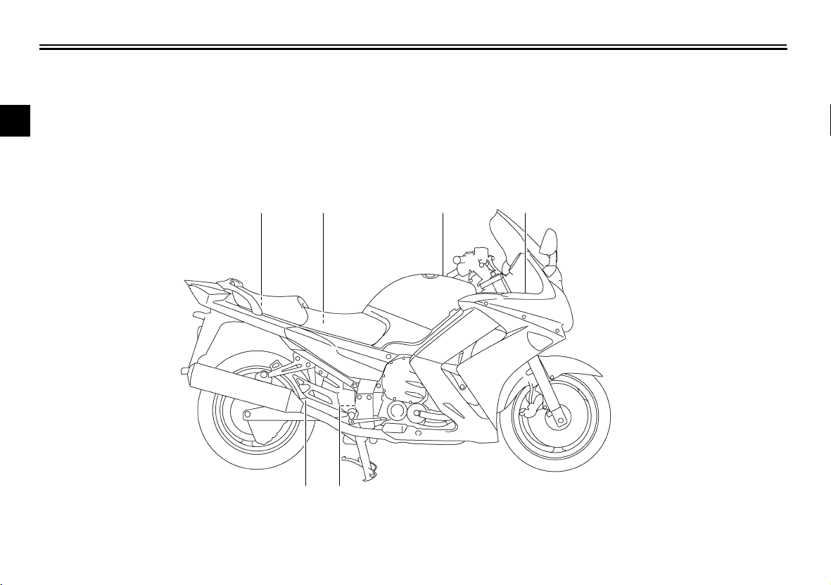
Left view
DESCRIPTION
EAU10410
3
1. Accessory box (page 4-20)
2. Front fork spring preload adjusting bolt (page 4-23)
3. Front fork rebound damping force adjusting knob (page 4-23)
4. Owner’s tool kit (page 7-2)
5. Rider seat (page 4-16)
6. Passenger seat (page 4-16)
7. Final gear oil filler bolt (page 7-18)
8. Final gear oil drain bolt (page 7-18)
9. Shock absorber assembly spring preload adjusting lever (page 4-25)
10.Air filter element (page 7-20)
11.Shift pedal (page 4-11)
12.Engine oil filler cap (page 7-15)
13.Engine oil filter cartridge (page 7-15)
14.Engine oil level check window (page 7-15)
3-1

DESCRIPTION
Right view
EAU10420
3
11 10 9 8
1. Storage compartment (page 4-19)
2. Fuel tank cap (page 4-13)
3. Fuse box (page 7-35)
4. ABS motor fuse (page 7-35)
5. Windshield (page 4-9)
6. Battery (page 7-34)
7. Main fuse (page 7-35)
8. Front fork compression damping force adjusting screw (page 4-23)
1 2
9. Brake pedal (page 4-12)
10.Shock absorber assembly rebound damping force adjusting knob
11.Rear brake fluid reservoir (page 7-27)
63,4 75
(page 4-25)
3-2

Controls and instruments
DESCRIPTION
EAU10430
3
1. Rear view mirror (page 4-23)
2. Clutch lever (page 4-10)
3. Left handlebar switches (page 4-9)
4. Clutch fluid reservoir (page 7-27)
5. Tachometer (page 4-4)
6. Speedometer (page 4-3)
7. Multi-function display (page 4-4)
8. Front brake fluid reservoir (page 7-27)
9. Right handlebar switches (page 4-9)
10.Brake lever (page 4-11)
11.Throttle grip (page 7-22)
12.Main switch/steering lock (page 4-1)
13.Headlight beam adjusting knob (page 4-21)
3-3

INSTRUMENT AND CONTROL FUNCTIONS
Main switch/steering lock
4
The main switch/steering lock controls
the ignition and lighting systems, and is
used to lock the steering. The various
positions are described below.
ON
All electrical circuits are supplied with
power, and the meter lighting, taillights,
license plate light and position lights
come on, and the engine can be started. The key cannot be removed.
TIP
The headlights come on automatically
when the engine is started and stay on
until the key is turned to “OFF”, even if
the engine stalls.
EAU10460
EAU35921
OFF
EAU10661
All electrical systems are off. The key
can be removed.
EWA10061
WARNING
Never turn the key to “OFF” or
“LOCK” while the vehicle is moving.
Otherwise the electrical systems will
be switched off, which may result in
loss of control or an accident.
EAU10691
LOCK
The steering is locked, and all electrical
systems are off. The key can be removed.
To lock the steering
1. Push.
2. Turn.
1. Turn the handlebars all the way to
the left or right.
2. Push the key in from the “OFF” po-
sition, and then turn it to “LOCK”
while still pushing it.
3. Remove the key.
4-1

INSTRUMENT AND CONTROL FUNCTIONS
To unlock the steering
1. Push.
2. Turn.
Push the key into the main switch, and
then turn it to “OFF” while still pushing
it.
EAU11004
Indicator and warning lights
1. Left turn signal indicator light “”
2. Right turn signal indicator light “”
3. Engine trouble warning light “”
4. Anti-lock Brake System (ABS) warning
5. Neutral indicator light “”
6. High beam indicator light “”
7. Oil level warning light “”
Turn signal indicator lights “”
and “”
The corresponding indicator light flashes when the turn signal switch is
pushed to the left or right.
ABS
light “”
EAU11030
Neutral indicator light “”
EAU11060
This indicator light comes on when the
transmission is in the neutral position.
EAU11080
High beam indicator light “”
This indicator light comes on when the
high beam of the headlight is switched
on.
EAU11123
Oil level warning light “”
This warning light comes on if the engine oil level is low.
The electrical circuit of the warning light
can be checked by turning the key to
“ON”. The warning light should come
on for a few seconds, and then go off.
If the warning light does not come on
initially when the key is turned to “ON”,
or if the warning light remains on, have
a Yamaha dealer check the electrical
circuit.
4
4-2

INSTRUMENT AND CONTROL FUNCTIONS
TIP
Even if the oil level is sufficient, the
warning light may flicker when riding on
a slope or during sudden acceleration
or deceleration, but this is not a malfunction.
Engine trouble warning light “”
This warning light comes on or flashes
4
if a problem is detected in the electrical
circuit monitoring the engine. If this occurs, have a Yamaha dealer check the
self-diagnosis system. (See page 4-8
for an explanation of the self-diagnosis
device.)
The electrical circuit of the warning light
can be checked by turning the key to
“ON”. The warning light should come
on for a few seconds, and then go off.
If the warning light does not come on
initially when the key is turned to “ON”,
or if the warning light remains on, have
a Yamaha dealer check the electrical
circuit.
EAU11534
ABS warning light “”
ABS
EAU39502
If this warning light comes on or flashes
while riding, the ABS may not work correctly. If this occurs, have a Yamaha
dealer check the system as soon as
possible. (See page 4-12.)
EWA10081
WARNING
If the ABS warning light comes on or
flashes while riding, the brake system reverts to conventional braking.
Therefore, be careful not to cause
the wheels to lock during emergency braking. If the warning light
comes on or flashes while riding,
have a Yamaha dealer check the
brake system as soon as possible.
The electrical circuit of the warning light
can be checked by turning the key to
“ON”. The warning light should come
on for a few seconds, and then go off.
If the warning light does not come on
initially when the key is turned to “ON”,
or if the warning light remains on, have
a Yamaha dealer check the electrical
circuit.
EAU11601
Speedometer
1. Tachometer
2. Speedometer
3. Multi-function display
The speedometer shows the riding
speed.
When the key is turned to “ON”, the
speedometer needle will sweep once
across the speed range and then return
to zero in order to test the electrical circuit.
4-3

INSTRUMENT AND CONTROL FUNCTIONS
EAU11872
Tachometer
1. Tachometer
2. Tachometer red zone
The electric tachometer allows the rider
to monitor the engine speed and keep it
within the ideal power range.
When the key is turned to “ON”, the tachometer needle will sweep once
across the r/min range and then return
to zero r/min in order to test the electrical circuit.
ECA10031
NOTICE
Do not operate the engine in the tachometer red zone.
Red zone: 9000 r/min and above
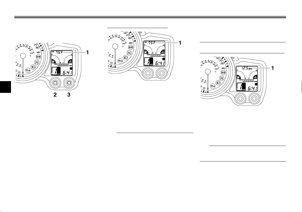
EAU40298
Multi-function display
1. Multi-function display
2. Select button
3. Reset button
EWA14431
WARNING
Be sure to stop the vehicle before
making any setting changes to the
multi-function display. Changing
settings while riding can distract the
operator and increase the risk of an
accident.
The multi-function display is equipped
with the following:
● an odometer
● two tripmeters (which show the
distance traveled since they were
last set to zero)
4-4
● a fuel reserve tripmeter (which
shows the distance traveled on the
fuel reserve)
● a clock
● a fuel meter
● a coolant temperature meter
● a transmission gear display
● an ambient temperature display
● a fuel consumption display (instan-
taneous and average consumption
functions)
● a self-diagnosis device
TIP
Be sure to turn the key to “ON” before
using the select and reset buttons.
4

INSTRUMENT AND CONTROL FUNCTIONS
Odometer and tripmeter modes
4
1. Odometer/tripmeter/fuel reserve tripmeter
2. Select button
3. Reset button
Pushing the select button switches the
display between the odometer mode
“ODO” and the tripmeter modes “Trip 1”
and “Trip 2” in the following order:
ODO → Trip 1 → Trip 2 → ODO
TIP
When selecting “Trip 1” or “Trip 2”, the
display flashes for five seconds.
When approximately 5.5 L (1.45 US
gal, 1.21 Imp.gal) of fuel remains in the
fuel tank, the display will automatically
change to the fuel reserve tripmeter
mode “Trip F” and start counting the
distance traveled from that point. In that
case, pushing the select button switches the display between the various tripmeter and odometer modes in the
following order:
Trip F → ODO → Trip 1 → Trip 2 → Trip
F
TIP
When selecting “Trip 1”, “Trip 2” or “Trip
F”, the display flashes for five seconds.
To reset a tripmeter, select it by pushing the select button, and then push the
select button for at least one second
while the display is flashing. If you do
not reset the fuel reserve tripmeter
manually, it will reset itself automatically and the display will return to the prior
mode after refueling and traveling 5 km
(3 mi).
Clock
1. Clock
2. Select button
3. Reset button
To set the clock:
1. Push the select button and reset
button together for at least two
seconds.
2. When the hour digits start flashing,
push the reset button to set the
hours.
3. Push the select button, and the
minute digits will start flashing.
4. Push the reset button to set the
minutes.
5. Push the select button and then release it to start the clock.
4-5

INSTRUMENT AND CONTROL FUNCTIONS
Fuel meter
1. Fuel meter
The fuel meter indicates the amount of
fuel in the fuel tank. The display segments of the fuel meter disappear towards “E” (Empty) as the fuel level
decreases. When the last segment
starts flashing, refuel as soon as possible.
When the key is turned to “ON”, all display segments come on once in order
to test the electrical circuit.
TIP
This fuel meter is equipped with a selfdiagnosis system. If a problem is detected in the electrical circuit, all display
segments will start flashing. If this occurs, have a Yamaha dealer check the
electrical circuit.
Coolant temperature meter
1. Coolant temperature meter
The coolant temperature meter indicates the temperature of the coolant.
The coolant temperature varies with
changes in the weather and engine
load. If the top segment flashes, stop
the vehicle, then stop the engine, and
let the engine cool. (See page 7-40.)
When the key is turned to “ON”, all display segments come on once in order
to test the electrical circuit.
ECA10021
NOTICE
Do not continue to operate the engine if it is overheating.
Transmission gear display
4
1. Transmission gear display
2. Neutral indicator light “”
This display shows the selected gear.
The neutral position, however, is not
displayed, it is indicated by the neutral
indicator light.
4-6
INSTRUMENT AND CONTROL FUNCTIONS
Ambient temperature, instantaneous fuel consumption and average fuel consumption modes
4
1. Ambient temperature/instantaneous fuel
consumption/average fuel consumption
2. Select button
3. Reset button
Push the reset button to switch the display between the ambient temperature
mode “Air”, the instantaneous fuel consumption mode “MPG” and the aver-
age fuel consumption mode “AV_ _._
MPG” in the following order:
Air → MPG → AV_ _._ MPG → Air
Ambient temperature mode
1. Ambient temperature
This display shows the ambient temperature from 16 °F to 122 °F in 1 °F increments. The temperature displayed
may vary from the ambient temperature.
TIP
● If the ambient temperature falls be-
low 16 °F, a lower temperature
than 16 °F will not be displayed.
● If the ambient temperature climbs
above 122 °F, a higher temperature than 122 °F will not be displayed.
● The accuracy of the temperature
reading may be affected when
riding slowly [approximately under
20 km/h (12.5 mi/h)] or when
stopped at traffic signals, railroad
crossings, etc.
Instantaneous fuel consumption mode
1. Instantaneous fuel consumption
This display shows the distance that
can be traveled on 1.0 US.gal of fuel
under the current riding conditions.
TIP
If traveling at speeds under 10 km/h
(6.0 mi/h), “_ _._” will be displayed.
4-7

INSTRUMENT AND CONTROL FUNCTIONS
Average fuel consumption mode
1. Average fuel consumption
This display shows the average fuel
consumption since it was last reset.
When the average fuel consumption
mode is selected, the display flashes
for five seconds, and then “AV_ _._
MPG” (average distance that can be
traveled using 1.0 US.gal of fuel) is displayed.
TIP
● To reset the average fuel con-
sumption display, push the reset
button to select the mode again,
and then push the reset button for
1 second while the display is flashing.
● After resetting the average fuel
consumption display, “_ _._” will
be shown for that display until the
vehicle has traveled 1 km (0.6 mi).
ECA15472
NOTICE
If there is a malfunction, “– –.–” will
be displayed. Have a Yamaha dealer
check the vehicle.
Self-diagnosis device
1. Error code display
This model is equipped with a self-diagnosis device for various electrical circuits.
If a problem is detected in any of those
circuits, the engine trouble warning light
will come on and the multi-function display will indicate an error code.
If the multi-function display indicates
such an error code, note the code number, and then have a Yamaha dealer
check the vehicle.
ECA11790
NOTICE
If the multi-function display indicates an error code, the vehicle
should be checked as soon as possible in order to avoid engine damage.
4
4-8

INSTRUMENT AND CONTROL FUNCTIONS
Handlebar switches
Left
4
1. Windshield position adjusting switch “”
2. Dimmer switch “ / ”
3. Turn signal switch “ / ”
4. Horn switch “”
EAU12348
Right
1. Engine stop switch “ / ”
2. Hazard switch “”
3. Start switch “”
EAU12400
Dimmer switch “ / ”
Set this switch to “” for the high
beam and to “” for the low beam.
EAU12460
Turn signal switch “ / ”
To signal a right-hand turn, push this
switch to “”. To signal a left-hand
turn, push this switch to “”. When re-
leased, the switch returns to the center
position. To cancel the turn signal
lights, push the switch in after it has returned to the center position.
Windshield position adjusting
EAU12493
switch “”
To move the windshield up, push this
switch in direction (a). To move the
windshield down, push the switch in direction (b).
1. Windshield position adjusting switch “”
TIP
When the key is turned to “OFF”, the
windshield will automatically return to
the lowest position.
EAU12500
Horn switch “”
Press this switch to sound the horn.
4-9

INSTRUMENT AND CONTROL FUNCTIONS
Engine stop switch “ / ”
EAU12660
Set this switch to “” before starting
the engine. Set this switch to “” to
stop the engine in case of an emergency, such as when the vehicle overturns
or when the throttle cable is stuck.
EAU12711
Start switch “”
Push this switch to crank the engine
with the starter. See page 6-1 for starting instructions prior to starting the engine.
EAU42340
The engine trouble warning light and
ABS warning light will come on when
the key is turned to “ON” and the start
switch is pushed, but this does not indicate a malfunction.
EAU12765
Hazard switch “”
With the key in the “ON” position, use
this switch to turn on the hazard lights
(simultaneous flashing of all turn signal
lights).
The hazard lights are used in case of
an emergency or to warn other drivers
when your vehicle is stopped where it
might be a traffic hazard.
ECA10061
NOTICE
Do not use the hazard lights for an
extended length of time with the engine not running, otherwise the battery may discharge.
4-10
EAU12830
Clutch lever
4
1. Clutch lever
2. Arrow mark
3. Clutch lever position adjusting dial
4. Distance between clutch lever and handlebar
grip
The clutch lever is located at the left
handlebar grip. To disengage the
clutch, pull the lever toward the handlebar grip. To engage the clutch, release
the lever. The lever should be pulled
rapidly and released slowly for smooth
clutch operation.
The clutch lever is equipped with a
clutch lever position adjusting dial. To
adjust the distance between the clutch
lever and the handlebar grip, turn the
adjusting dial while holding the lever
pushed away from the handlebar grip.

INSTRUMENT AND CONTROL FUNCTIONS
Make sure that the appropriate setting
on the adjusting dial is aligned with the
arrow mark on the clutch lever.
The clutch lever is equipped with a
clutch switch, which is part of the ignition circuit cut-off system. (See page
4-27.)
4
EAU12870
Shift pedal
1. Shift pedal
The shift pedal is located on the left
side of the engine and is used in combination with the clutch lever when
shifting the gears of the 5-speed constant-mesh transmission equipped on
this motorcycle.
4-11
EAU26823
Brake lever
The brake lever is located at the right
handlebar grip. To apply the front
brake, pull the lever toward the handlebar grip.
1. Brake lever
2. “” mark
3. Brake lever position adjusting dial
4. Distance between brake lever and handlebar
grip
The brake lever is equipped with a
brake lever position adjusting dial. To
adjust the distance between the brake
lever and the handlebar grip, turn the
adjusting dial while holding the lever
pushed away from the handlebar grip.
Make sure that the appropriate setting
on the adjusting dial is aligned with
the “” mark on the brake lever.

INSTRUMENT AND CONTROL FUNCTIONS
EAU39540
Brake pedal
1. Brake pedal
The brake pedal is on the right side of
the vehicle.
This model is equipped with a unified
brake system.
When pressing down on the brake pedal, the rear brake and a portion of the
front brake are applied. For full braking
performance, apply both the brake lever and the brake pedal simultaneously.
EAU39533
ABS
The Yamaha ABS (Anti-lock Brake
System) features a dual electronic control system, which acts on the front and
rear brakes independently. The ABS is
monitored by an ECU, which will have
recourse to manual braking if a malfunction occurs.
EWA10090
WARNING
● The ABS performs best on long
braking distances.
● On certain (rough or gravel)
roads, the braking distance may
be longer with than without the
ABS. Therefore, always keep a
sufficient distance to the vehicle
ahead to match the riding
speed.
TIP
● The ABS performs a self-diagno-
sis test for a few seconds each
time the vehicle first starts off after
the key was turned to “ON”. During
this test, a “clicking” noise can be
heard from under the seat, and if
the brake lever or brake pedal are
even slightly applied, a vibration
can be felt at the lever and pedal,
but these do not indicate a malfunction.
● When the ABS is activated, the
brakes are operated in the usual
way. A pulsating action may be felt
at the brake lever or brake pedal,
but this does not indicate a malfunction.
● This ABS has a test mode which
allows the owner to experience the
pulsating at the brake lever or
brake pedal when the ABS is operating. However, special tools are
required, so please consult your
Yamaha dealer when performing
this test.
ECA16120
NOTICE
Keep any type of magnets (including
magnetic pick-up tools, magnetic
screwdrivers, etc.) away from the
front and rear wheel hubs, otherwise
the magnetic rotors equipped in the
wheel hubs may be damaged, resulting in improper performance of the
ABS system.
4
4-12
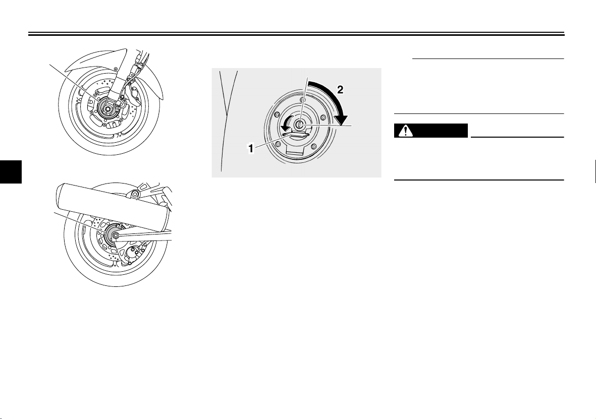
INSTRUMENT AND CONTROL FUNCTIONS
1
1. Front wheel hub
4
1. Rear wheel hub
EAU13074
Fuel tank cap
TIP
The fuel tank cap cannot be closed unless the key is in the lock. In addition,
the key cannot be removed if the cap is
not properly closed and locked.
EWA11091
WARNING
Make sure that the fuel tank cap is
properly closed after filling fuel.
Leaking fuel is a fire hazard.
1. Fuel tank cap lock cover
2. Unlock.
1
To open the fuel tank cap
Open the fuel tank cap lock cover, insert the key into the lock, and then turn
it 1/4 turn clockwise. The lock will be released and the fuel tank cap can be
opened.
To close the fuel tank cap
1. Push the fuel tank cap into position
with the key inserted in the lock.
2. Turn the key counterclockwise to
the original position, remove it, and
then close the lock cover.
4-13
 Loading...