

Yamaha FJR1300AE User Manual
Read this manual carefully before operating this vehicle.
OWNER’S MANUAL
FJR1300AE
2PD-28199-EH
EAU70090
Date of issue:
Signature of Responsible Person:
January 12, 2015
Product: IMMOBILIZER
Model: 1MC-00
Supplied by
YAMAHA MOTOR ELECTRONICS
CO.,LTD.
1450-6 Mori, Mori-machi Shuchi-gun
Shizuoka 437-0292 Japan
EN 60950-1: 2006 + Amd.11:2009 + Amd.1:2010 +
Amd.12: 2011
EN 62479: 2010
Kazuhide Takasugi
GENERAL MANAGER
QUALITY ASSURANCE DIV.
97/24/EC from 17.06.1997
EN 300 330-1 V1.7.1: 2010
EN 300 330-2 V1.5.1: 2010
Technical Construction File held by
YAMAHA MOTOR ELECTRONICS
CO.,LTD.
1450-6 Mori, Mori-machi Shuchi-gun
Shizuoka 437-0292 Japan
R&TTE Directive
(Article 3.1(a) Safety)
R&TTE Directive
(Article 3.1(b) EMC)
R&TTE Directive
(Article 3.2 Spectrum)
DECLARATION of CONFORMITY
For
YAMAHA MOTOR ELECTRONICS CO., LTD.
1450-6, Mori, Mori-machi, Shuchi-gun, Shizuoka-ken, 437-0292 Japan
Standard used for comply
Means of Conformity
We declare under our sole responsibility that the Product (s) is conformity with the essential
requirements and other relevant requirements of the
Radio and Telecommunication Terminal Equipment (R&TTE) Directive (1999/5/EC).
Read this manual carefully before operating this vehicle. This manual should stay with this vehicle if it is sold.
INTRODUCTION
WARNING
EAU10103
Welcome to the Yamaha world of motorcycling!
As the owner of the FJR1300AE, you are benefiting from Yamaha’s vast experience and newest technology regarding the
design and manufacture of high-quality products, which have earned Yamaha a reputation for dependability.
Please take the time to read this manual thoroughly, so as to enjoy all advantages of your FJR1300AE. The Owner’s Manual
does not only instruct you in how to operate, inspect and maintain your motorcycle, but also in how to safeguard yourself
and others from trouble and injury.
In addition, the many tips given in this manual will help keep your motorcycle in the best possible condition. If you have any
further questions, do not hesitate to contact your Yamaha dealer.
The Yamaha team wishes you many safe and pleasant rides. So, remember to put safety first!
Yamaha continually seeks advancements in product design and quality. Therefore, while this manual contains the most current product information available at the time of printing, there may be minor discrepancies between your motorcycle and
this manual. If there is any question concerning this manual, please consult a Yamaha dealer.
Please read this manual carefully and completely before operating this motorcycle.
EWA10032
IMPORTANT MANUAL INFORMATION
WARNING
NOTICE
TIP
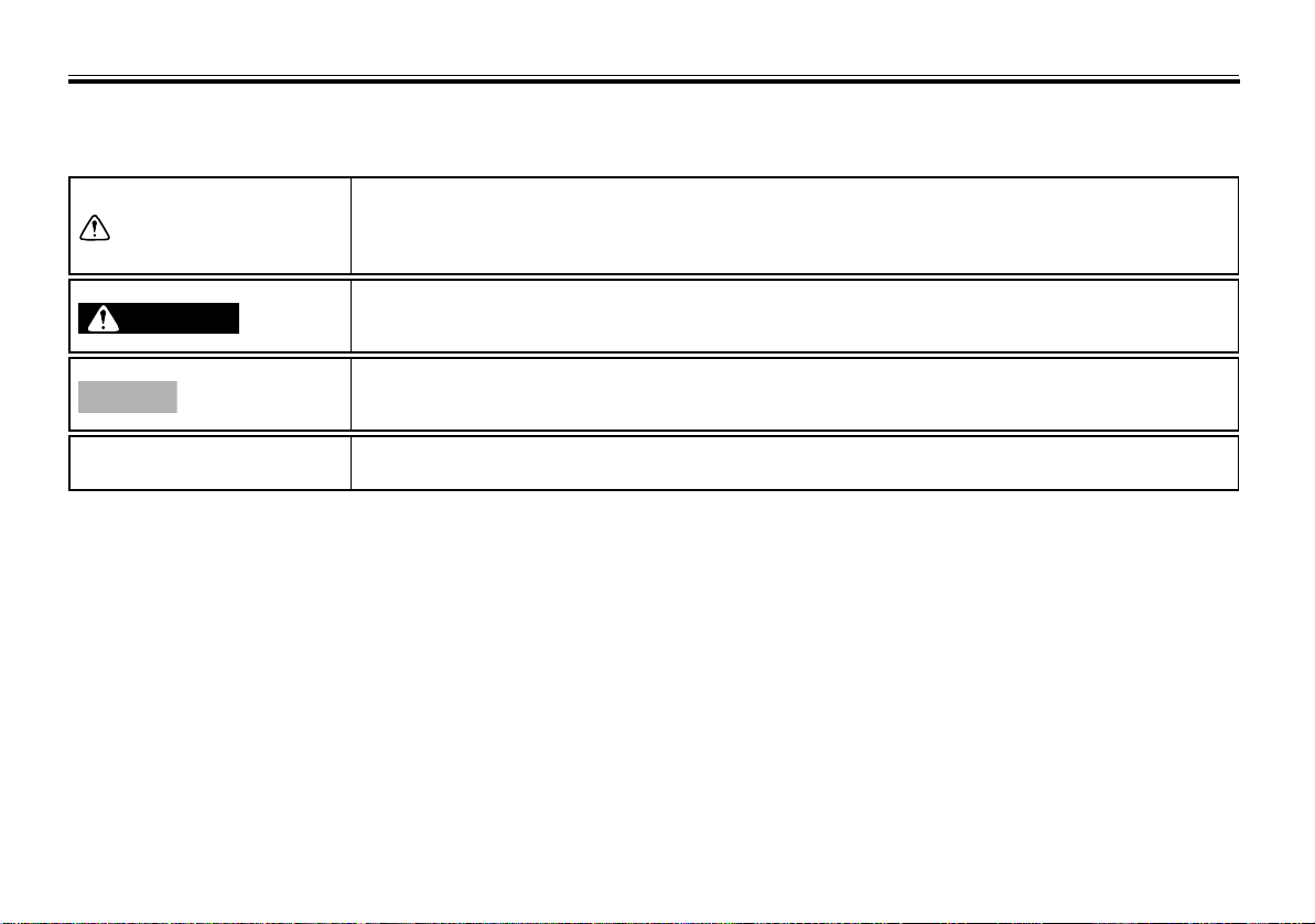
Particularly important information is distinguished in this manual by the following notations:
This is the safety alert symbol. It is used to alert you to potential personal injury
hazards. Obey all safety messages that follow this symbol to avoid possible injury
or death.
A WARNING indicates a hazardous situation which, if not avoided, could result in
death or serious injury.
A NOTICE ind icates special precautions that must be taken to avoid damage to the
vehicle or other property.
A TIP provides key information to make procedures easier or clearer.
*Product and specifications are subject to change without notice.
EAU10134

IMPORTANT MANUAL INFORMATION
FJR1300AE
OWNER’S MANUAL
©2015 by Yamaha Motor Co., Ltd.
1st edition, April 2015
All rights reserved.
Any reprinting or unauthorized use
without the written permission of
Yamaha Motor Co., Ltd.
is expressly prohibited.
Printed in Japan.
EAU10201

TABLE OF CONTENTS
SAFETY INFORMATION .................. 1-1
DESCRIPTION .................................. 2-1
Left view ......................................... 2-1
Right view....................................... 2-2
Controls and instruments............... 2-3
INSTRUMENT AND CONTROL
FUNCTIONS ...................................... 3-1
Immobilizer system......................... 3-1
Main switch/steering lock............... 3-2
Indicator lights and warning
lights............................................ 3-4
Cruise control system..................... 3-7
Multi-function meter unit .............. 3-10
D-mode (drive mode).................... 3-24
Handlebar switches...................... 3-24
Clutch lever .................................. 3-26
Shift pedal .................................... 3-27
Brake lever.................................... 3-27
Brake pedal .................................. 3-27
ABS .............................................. 3-28
Traction control system................ 3-29
Fuel tank cap................................ 3-30
Fuel............................................... 3-31
Fuel tank breather/overflow
hose .......................................... 3-32
Catalytic converters...................... 3-32
Seats ............................................ 3-33
Adjusting the rider seat height...... 3-34
Storage compartments................. 3-36
Accessory box ..............................3-37
Adjusting the headlight beams .....3-38
Handlebar position........................3-38
Opening and closing the cowling
vents ..........................................3-38
Rear view mirrors ..........................3-40
Adjusting the front and rear
suspension ................................3-40
Sidestand......................................3-44
Ignition circuit cut-off system .......3-45
Auxiliary DC jack...........................3-47
FOR YOUR SAFETY –
PRE-OPERATION CHECKS .............4-1
OPERATION AND IMPORTANT
RIDING POINTS ................................5-1
Starting the engine..........................5-1
Shifting............................................5-2
Tips for reducing fuel
consumption................................5-3
Engine break-in...............................5-3
Parking............................................5-4
PERIODIC MAINTENANCE AND
ADJUSTMENT ...................................6-1
Owner’s tool kit...............................6-2
Periodic maintenance chart for the
emission control system..............6-3
General maintenance and
lubrication chart...........................6-4
Removing and installing panels...... 6-8
Checking the spark plugs............. 6-11
Engine oil and oil filter cartridge ... 6-12
Final gear oil ................................. 6-14
Coolant ......................................... 6-16
Cleaning the air filter element....... 6-17
Checking the engine idling
speed ........................................ 6-18
Checking the throttle grip free
play............................................ 6-19
Valve clearance............................. 6-19
Tires .............................................. 6-19
Cast wheels .................................. 6-22
Clutch lever................................... 6-22
Checking the brake lever free
play............................................ 6-22
Brake light switches ..................... 6-23
Checking the front and rear brake
pads .......................................... 6-23
Checking the brake and clutch
fluid levels.................................. 6-24
Changing the brake and clutch
fluids.......................................... 6-25
Checking and lubricating the
cables........................................ 6-26
Checking and lubricating the
throttle grip and cable............... 6-26
Checking and lubricating the
brake and shift pedals............... 6-26
Checking and lubricating the
brake and clutch levers............. 6-27

Checking and lubricating the
centerstand and sidestand ........6-28
Lubricating the rear suspension....6-28
Lubricating the swingarm pivots ...6-29
Checking the front fork..................6-29
Checking the steering ...................6-30
Checking the wheel bearings........6-30
Battery...........................................6-30
Replacing the fuses.......................6-32
Headlight bulb ...............................6-33
Auxiliary light .................................6-34
Front turn signal light.....................6-34
Replacing a rear turn signal light
bulb or a tail/brake light bulb.....6-34
Replacing the license plate light
bulb ............................................6-35
Troubleshooting ............................6-36
Troubleshooting charts .................6-37
MOTORCYCLE CARE AND
STORAGE ..........................................7-1
Matte color caution .........................7-1
Care.................................................7-1
Storage............................................7-4
TABLE OF CONTENTS
SPECIFICATIONS..............................8-1
CONSUMER INFORMATION............9-1
Identification numbers.....................9-1
INDEX...............................................10-1

SAFETY INFORMATION
1
Be a Responsible Owner
As the vehicle’s owner, you are responsible for the safe and proper operation of your motorcycle.
Motorcycles are single-track vehicles.
Their safe use and operation are dependent upon the use of proper riding
techniques as well as the expertise of
the operator. Every operator should
know the following requirements before riding this motorcycle.
He or she should:
Obtain thorough instructions from
a competent source on all aspects
of motorcycle operation.
Observe the warnings and mainte-
nance requirements in this Own-
er’s Manual.
Obtain qualified training in safe
and proper riding techniques.
Obtain professional technical ser-
vice as indicated in this Owner’s
Manual and/or when made neces-
sary by mechanical conditions.
EAU1028B
Never operate a motorcycle with-
out proper training or instruction.
Take a training course. Beginners
should receive training from a certified instructor. Contact an authorized motorcycle dealer to find out
about the training courses nearest
you.
Safe Riding
Perform the pre-operation checks
each time you use the vehicle to make
sure it is in safe operating condition.
Failure to inspect or maintain the vehicle properly increases the possibility of
an accident or equipment damage.
See page 4-1 for a list of pre-operation
checks.
This motorcycle is designed to
carry the operator and a passenger.
The failure of motorists to detect
and recognize motorcycles in traffic is the predominating cause of
automobile/motorcycle accidents.
Many accidents have been
caused by an automobile driver
who did not see the motorcycle.
Making yourself conspicuous ap-
1-1
pears to be very effective in reducing the chance of this type of
accident.
Therefore:
• Wear a brightly colored jacket.
• Use extra caution when you are
approaching and passing
through intersections, since intersections are the most likely
places for motorcycle accidents
to occur.
• Ride where other motorists can
see you. Avoid riding in another
motorist’s blind spot.
• Never maintain a motorcycle
without proper knowledge.
Contact an authorized motorcycle dealer to inform you on basic motorcycle maintenance.
Certain maintenance can only
be carried out by certified staff.
SAFETY INFORMATION
Many accidents involve inexperi-
enced operators. In fact, many operators who have been involved in
accidents do not even have a current motorcycle license.
• Make sure that you are qualified
and that you only lend your motorcycle to other qualified operators.
• Know your skills and limits.
Staying within your limits may
help you to avoid an accident.
• We recommend that you practice riding your motorcycle
where there is no traffic until you
have become thoroughly familiar with the motorcycle and all of
its controls.
Many accidents have been
caused by error of the motorcycle
operator. A typical error made by
the operator is veering wide on a
turn due to excessive speed or undercornering (insufficient lean angle for the speed).
• Always obey the speed limit and
never travel faster than warranted by road and traffic conditions.
• Always signal before turning or
changing lanes. Make sure that
other motorists can see you.
The posture of the operator and
passenger is important for proper
control.
• The operator should keep both
hands on the handlebar and
both feet on the operator footrests during operation to maintain control of the motorcycle.
• The passenger should always
hold onto the operator, the seat
strap or grab bar, if equipped,
with both hands and keep both
feet on the passenger footrests.
Never carry a passenger unless
he or she can firmly place both
feet on the passenger footrests.
Never ride under the influence of
alcohol or other drugs.
This motorcycle is designed for
on-road use only. It is not suitable
for off-road use.
1-2
Protective Apparel
The majority of fatalities from motorcycle accidents are the result of head injuries. The use of a safety helmet is the
single most critical factor in the prevention or reduction of head injuries.
Always wear an approved helmet.
Wear a face shield or goggles.
Wind in your unprotected eyes
could contribute to an impairment
of vision that could delay seeing a
hazard.
The use of a jacket, heavy boots,
trousers, gloves, etc., is effective
in preventing or reducing abrasions or lacerations.
Never wear loose-fitting clothes,
otherwise they could catch on the
control levers, footrests, or wheels
and cause injury or an accident.
Always wear protective clothing
that covers your legs, ankles, and
feet. The engine or exhaust system become very hot during or after operation and can cause
burns.
A passenger should also observe
the above precautions.
1
SAFETY INFORMATION
Avoid Carbon Monoxide Poisoning
1
All engine exhaust contains carbon
monoxide, a deadly gas. Breathing
carbon monoxide can cause headaches, dizziness, drowsiness, nausea,
confusion, and eventually death.
Carbon Monoxide is a colorless, odorless, tasteless gas which may be present even if you do not see or smell any
engine exhaust. Deadly levels of carbon monoxide can collect rapidly and
you can quickly be overcome and unable to save yourself. Also, deadly levels of carbon monoxide can linger for
hours or days in enclosed or poorly
ventilated areas. If you experience any
symptoms of carbon monoxide poisoning, leave the area immediately, get
fresh air, and SEEK MEDICAL TREATMENT.
Do not run engine indoors. Even if
you try to ventilate engine exhaust
with fans or open windows and
doors, carbon monoxide can rapidly reach dangerous levels.
Do not run engine in poorly venti-
lated or partially enclosed areas
such as barns, garages, or carports.
Do not run engine outdoors where
engine exhaust can be drawn into
a building through openings such
as windows and doors.
Loading
Adding accessories or cargo to your
motorcycle can adversely affect stability and handling if the weight distribution of the motorcycle is changed. To
avoid the possibility of an accident, use
extreme caution when adding cargo or
accessories to your motorcycle. Use
extra care when riding a motorcycle
that has added cargo or accessories.
Here, along with the information about
accessories below, are some general
guidelines to follow if loading cargo to
your motorcycle:
The total weight of the operator, passenger, accessories and cargo must
not exceed the maximum load limit.
Operation of an overloaded vehicle
could cause an accident.
Maximum load:
212 kg (467 lb)
1-3
When loading within this weight limit,
keep the following in mind:
Cargo and accessory weight
should be kept as low and close to
the motorcycle as possible. Securely pack your heaviest items as
close to the center of the vehicle
as possible and make sure to distribute the weight as evenly as
possible on both sides of the motorcycle to minimize imbalance or
instability.
Shifting weights can create a sud-
den imbalance. Make sure that
accessories and cargo are securely attached to the motorcycle
before riding. Check accessory
mounts and cargo restraints frequently.
• Properly adjust the suspension
for your load (suspension-adjustable models only), and
check the condition and pressure of your tires.
• Never attach any large or heavy
items to the handlebar, front
fork, or front fender. These
items, including such cargo as
sleeping bags, duffel bags, or

SAFETY INFORMATION
tents, can create unstable handling or a slow steering response.
This vehicle is not designed to
pull a trailer or to be attached to
a sidecar.
Genuine Yamaha Accessories
Choosing accessories for your vehicle
is an important decision. Genuine
Yamaha accessories, which are available only from a Yamaha dealer, have
been designed, tested, and approved
by Yamaha for use on your vehicle.
Many companies with no connection
to Yamaha manufacture parts and accessories or offer other modifications
for Yamaha vehicles. Yamaha is not in
a position to test the products that
these aftermarket companies produce.
Therefore, Yamaha can neither endorse nor recommend the use of accessories not sold by Yamaha or
modifications not specifically recommended by Yamaha, even if sold and
installed by a Yamaha dealer.
Aftermarket Parts, Accessories, and
Modifications
While you may find aftermarket products similar in design and quality to
genuine Yamaha accessories, recognize that some aftermarket accessories or modifications are not suitable
because of potential safety hazards to
you or others. Installing aftermarket
products or having other modifications
performed to your vehicle that change
any of the vehicle’s design or operation
characteristics can put you and others
at greater risk of serious injury or
death. You are responsible for injuries
related to changes in the vehicle.
Keep the following guidelines in mind,
as well as those provided under “Loading” when mounting accessories.
Never install accessories or carry
cargo that would impair the performance of your motorcycle.
Carefully inspect the accessory
before using it to make sure that it
does not in any way reduce
ground clearance or cornering
clearance, limit suspension travel,
steering travel or control operation, or obscure lights or reflectors.
• Accessories fitted to the handlebar or the front fork area can
create instability due to improper weight distribution or aerodynamic changes. If accessories
are added to the handlebar or
front fork area, they must be as
lightweight as possible and
should be kept to a minimum.
• Bulky or large accessories may
seriously affect the stability of
the motorcycle due to aerodynamic effects. Wind may attempt to lift the motorcycle, or
the motorcycle may become
unstable in cross winds. These
accessories may also cause instability when passing or being
passed by large vehicles.
• Certain accessories can displace the operator from his or
her normal riding position. This
improper position limits the
freedom of movement of the
1
1-4

SAFETY INFORMATION
1
operator and may limit control
ability, therefore, such accessories are not recommended.
Use caution when adding electri-
cal accessories. If electrical accessories exceed the capacity of
the motorcycle’s electrical system, an electric failure could result, which could cause a
dangerous loss of lights or engine
power.
Aftermarket Tires and Rims
The tires and rims that came with your
motorcycle were designed to match
the performance capabilities and to
provide the best combination of handling, braking, and comfort. Other
tires, rims, sizes, and combinations
may not be appropriate. Refer to page
6-19 for tire specifications and more information on replacing your tires.
Transporting the Motorcycle
Be sure to observe following instructions before transporting the motorcycle in another vehicle.
Remove all loose items from the
motorcycle.
Check that the fuel cock (if
equipped) is in the “OFF” position
and that there are no fuel leaks.
Point the front wheel straight
ahead on the trailer or in the truck
bed, and choke it in a rail to prevent movement.
Shift the transmission in gear (for
models with a manual transmission).
Secure the motorcycle with tie-
downs or suitable straps that are
attached to solid parts of the motorcycle, such as the frame or upper front fork triple clamp (and not,
for example, to rubber-mounted
handlebars or turn signals, or
parts that could break). Choose
the location for the straps carefully
so the straps will not rub against
painted surfaces during transport.
The suspension should be com-
pressed somewhat by the tiedowns, if possible, so that the motorcycle will not bounce excessively during transport.
1-5
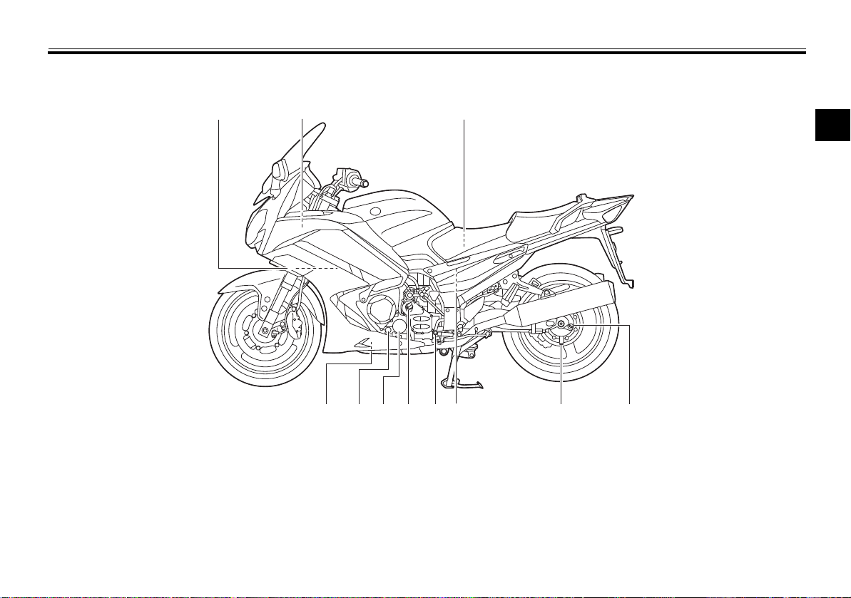
Left view
1
2
3
4
5
67891011
DESCRIPTION
EAU10411
2
1. Coolant reservoir (page 6-16)
2. Accessory box (page 3-37)
3. Owner’s tool kit (page 6-2)
4. Final gear oil filler bolt (page 6-14)
5. Final gear oil drain bolt (page 6-14)
6. Air filter element (page 6-17)
7. Shift pedal (page 3-27)
8. Engine oil filler cap (page 6-12)
9. Engine oil filter cartridge (page 6-12)
10.Engine oil level check window (page 6-12)
11.Engine oil drain bolt (page 6-12)
2-1
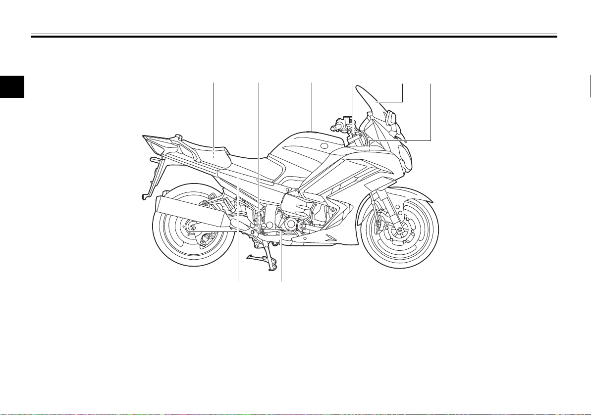
DESCRIPTION
Right view
2
1. Storage compartment (page 3-36)
2. Electronically adjustable suspension system (page 3-40)
3. Fuel tank cap (page 3-30)
4. Windshield (page 3-13)
5. Fuses (page 6-32)
6. Battery (page 6-30)
7. Brake pedal (page 3-27)
8. Rear brake fluid reservoir (page 6-24)
EAU10421
5,6
4231 2
78
2-2
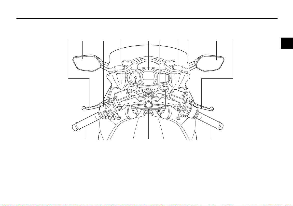
Controls and instruments
12 3 4 56 78 2 9
10,1112
11
DESCRIPTION
EAU10431
2
1. Clutch lever (page 3-26)
2. Rear view mirror (page 3-40)
3. Left handlebar switches (page 3-24)
4. Clutch fluid reservoir (page 6-24)
5. Multi-function meter unit (page 3-10)
6. Main switch/steering lock (page 3-2)
7. Front brake fluid reservoir (page 6-24)
8. Right handlebar switches (page 3-24)
9. Brake lever (page 3-27)
10.Throttle grip (page 6-19)
11.Grip warmer (page 3-13)
12.Headlight beam adjusting knob (page 3-38)
2-3
INSTRUMENT AND CONTROL FUNCTIONS
NOTICE
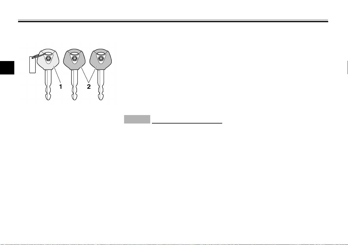
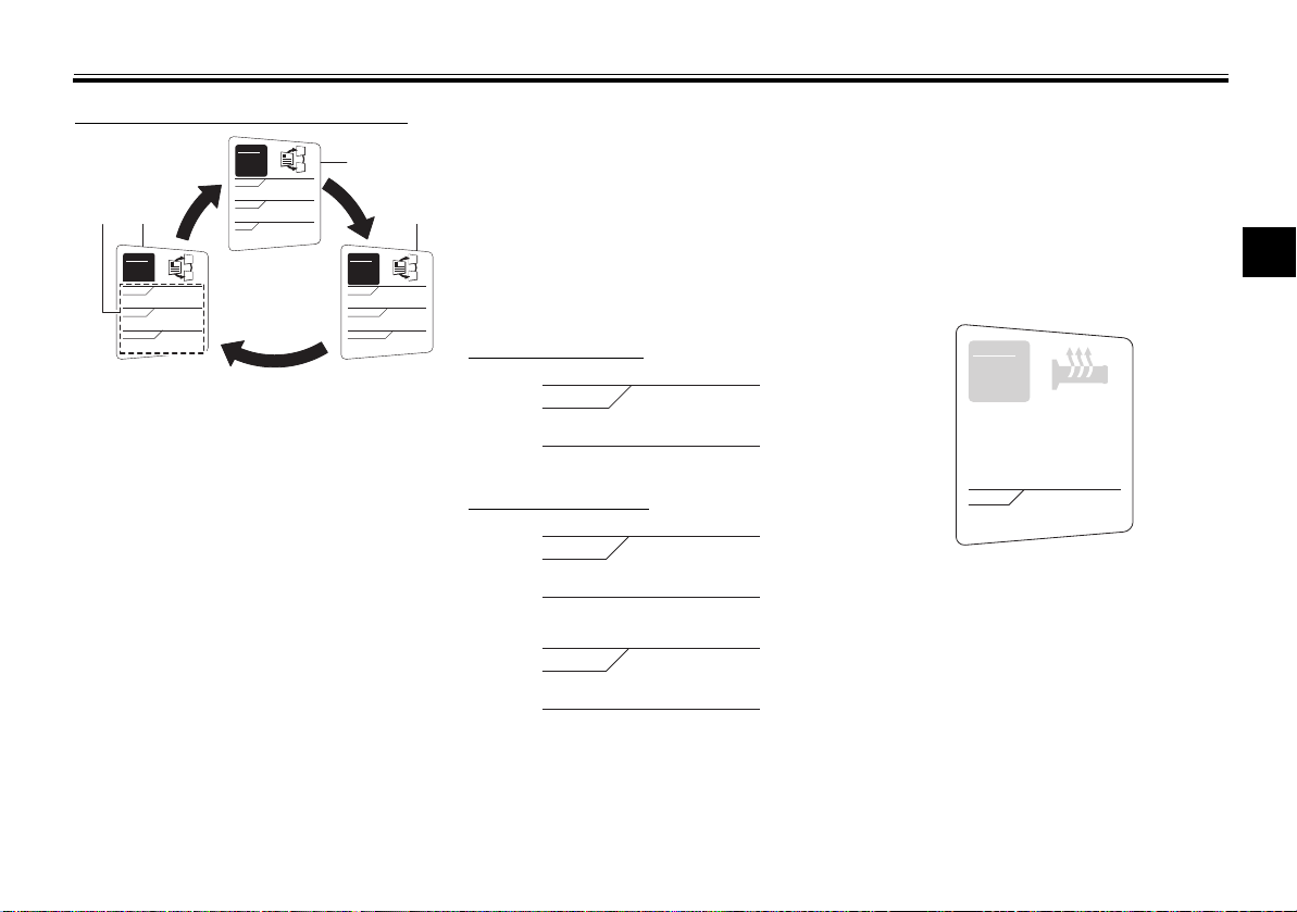
Immobilizer system
3
1. Code re-registering key (red bow)
2. Standard keys (black bow)
This vehicle is equipped with an immobilizer system to help prevent theft by
re-registering codes in the standard
keys. This system consists of the following:
a code re-registering key (with a
red bow)
two standard keys (with a black
bow) that can be re-registered
with new codes
a transponder (which is installed in
the code re-registering key)
an immobilizer unit
an ECU
EAU10978
an immobilizer system indicator
light (See page 3-6.)
The key with the red bow is used to
register codes in each standard key.
Since re-registering is a difficult process, take the vehicle along with all
three keys to a Yamaha dealer to have
them re-registered. Do not use the key
with the red bow for driving. It should
only be used for re-registering the
standard keys. Always use a standard
key for driving.
ECA11822
DO NOT LOSE THE CODE RE-
REGISTERING KEY! CONTACT
YOUR DEALER IMMEDIATELY
IF IT IS LOST! If the code re-reg-
istering key is lost, registering
new codes in the standard keys
is impossible. The standard
keys can still be used to start
the vehicle, however if code re-
registering is required (i.e., if a
new standard key is made or all
keys are lost) the entire immobi-
lizer system must be replaced.
Therefore, it is highly recom-
mended to use either standard
key and keep the code re-regis-
tering key in a safe place.
Do not submerse any key in wa-
ter.
Do not expose any key to exces-
sively high temperatures.
Do not place any key close to
magnets (this includes, but not
limited to, products such as
speakers, etc.).
t place items that transmit
Do n
o
electrical signals close to any
key.
Do not place heavy items on any
key.
Do not grind any key or alter its
shape.
Do not disassemble the plastic
part of any key.
Do not put two keys of any im-
mobilizer system on the same
key ring.
Keep the standard keys as well
as keys of other immobilizer
systems away from this vehicle’s code re-registering key.
3-1

INSTRUMENT AND CONTROL FUNCTIONS
TIP
TIP
WARNING
P
ON
OFF
LOCK
Keep other immobilizer system
keys away from the main switch
as they may cause signal interference.
EAU10473
Main switch/steering lock
The main switch/steering lock controls
the ignition and lighting systems, and is
used to lock the steering. The various
positions are described below.
Be sure to use the standard key (black
bow) for regular use of the vehicle. To
minimize the risk of losing the code reregistering key (red bow), keep it in a
safe place and only use it for code reregistering.
3-2
ON
EAU26812
All electrical circuits are supplied with
power; the meter lighting, taillights, license plate light and auxiliary lights
come on, and the engine can be started. The key cannot be removed.
The headlights come on automatically
when the engine is started and stay on
until the key is turned to “OFF”.
EAU10662
OFF
All electrical systems are off. The key
can be removed.
EWA10062
Never turn the key to “OFF” or
“LOCK” while the vehicle is moving.
Otherwise the electrical systems will
be switched off, which may result in
loss of control or an accident.
EAU10693
LOCK
The steering is locked, and all electrical
systems are off. The key can be removed.
3
INSTRUMENT AND CONTROL FUNCTIONS
NOTICE
12
12
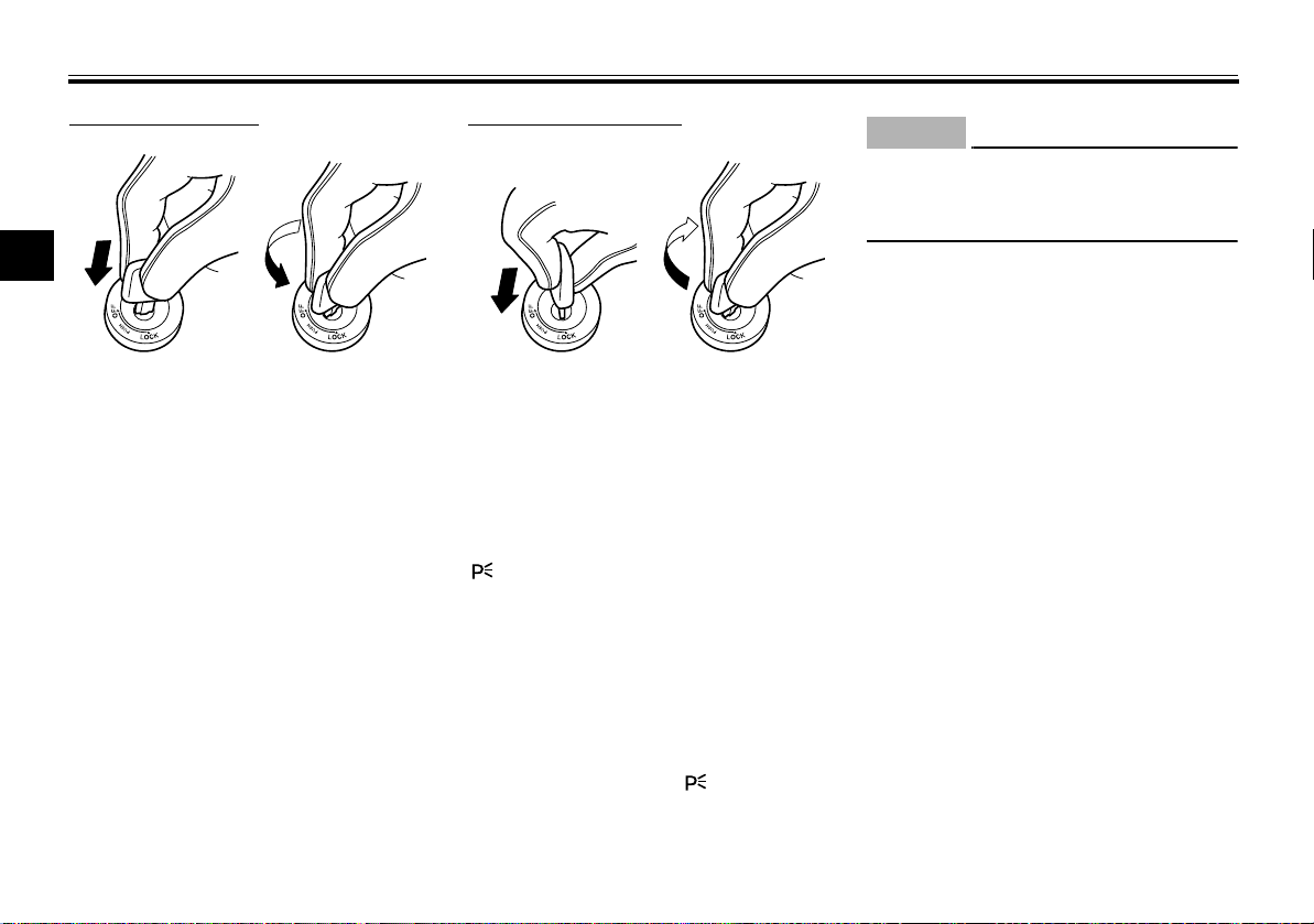
To lock the steering
3
1. Push.
2. Turn.
1. Turn the handlebars all the way to
the left or right.
2. Push the key in from the “OFF”
position, and then turn it to
“LOCK” while still pushing it.
3. Remove the key.
To unlock the steering
1. Push.
2. Turn.
Push the key into the main switch, and
then turn it to “OFF” while still pushing
it.
EAU39461
(Parking)
The steering is locked, and the taillights, license plate light and auxiliary
lights are on. The hazard lights and turn
signal lights can be turned on, but all
other electrical systems are off. The
key can be removed.
The steering must be locked before the
key can be turned to “ ”.
ECA11021
Do not use the parking position for
an extended length of time, otherwise the battery may discharge.
3-3
INSTRUMENT AND CONTROL FUNCTIONS
TIP
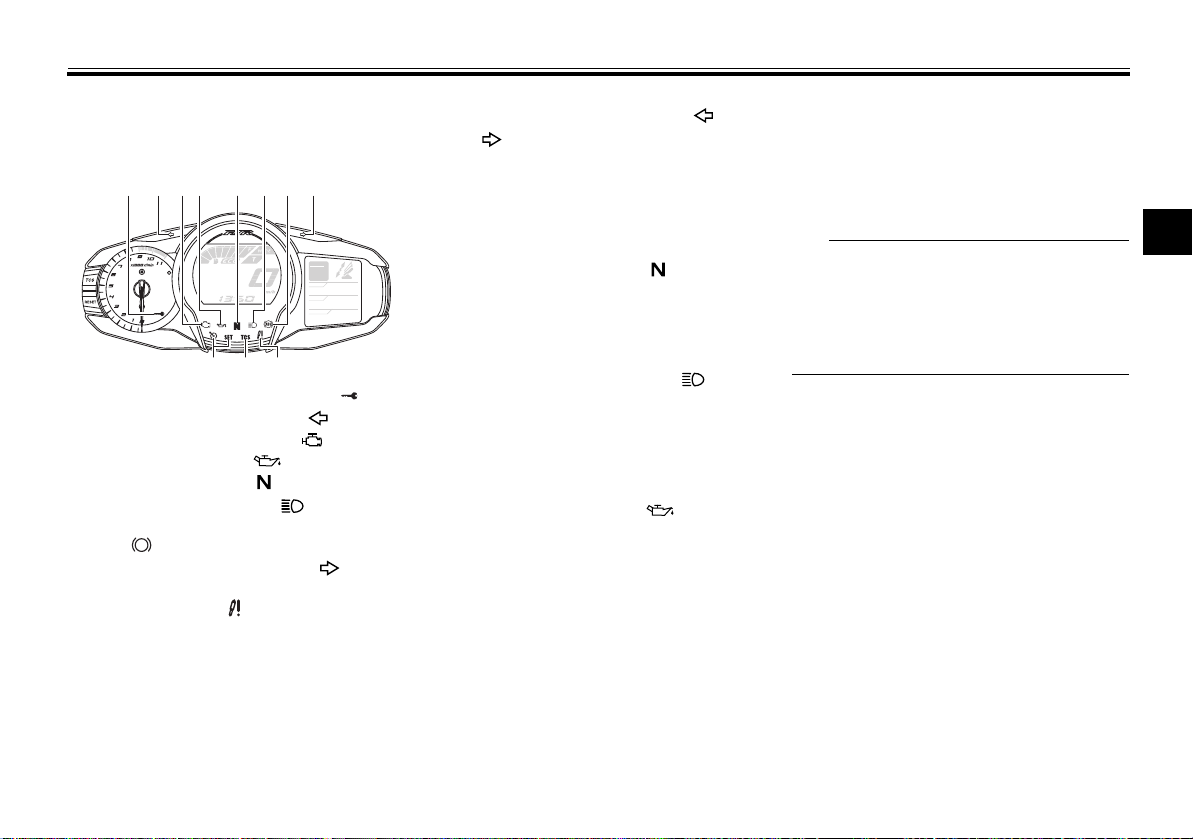
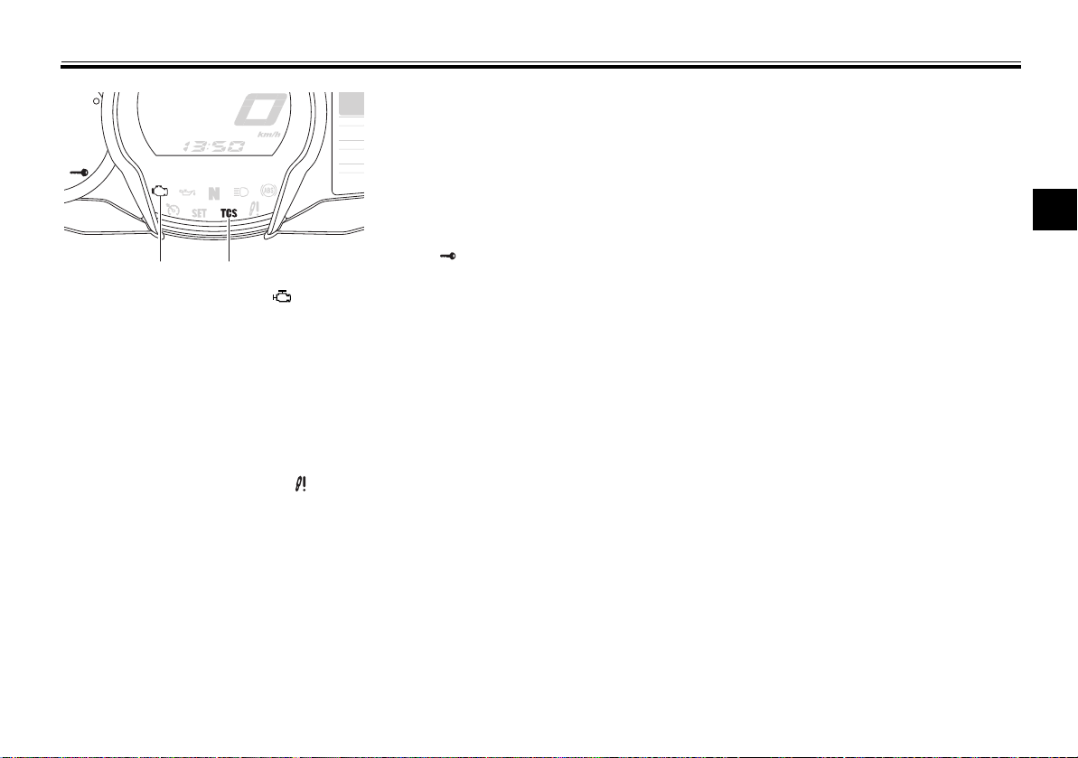
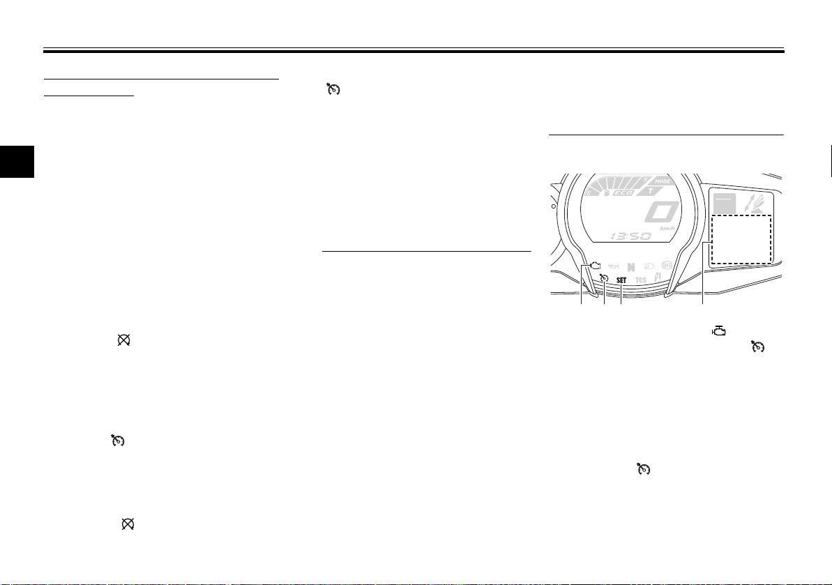
1 2 83 74
1011
65
9
ABS
Indicator lights and warning lights
GEAR
N
A.TEMP ˚C
C.TEMP ˚C
TIME TRIP
0:06
1. Immobilizer system indicator light “ ”
2. Left turn signal indicator light “ ”
3. Engine trouble warning light “ ”
4. Oil level warning light “ ”
5. Neutral indicator light “ ”
6. High beam indicator light “ ”
7. Anti-lock Brake System (ABS) warning
light “ ”
8. Right turn signal indicator light “ ”
9. Electronically adjustable suspension system warning light “ ”
10.Traction control system indicator/warning
light “TCS”
11.Cruise control indicator lights
EAU49396
25
Lo
Turn signal indicator lights “ ”
EAU11031
and “”
The corresponding indicator light
flashes when the turn signal switch is
pushed to the left or right.
EAU11061
Neutral indicator light “ ”
This indicator light comes on when the
transmission is in the neutral position.
EAU11081
High beam indicator light “ ”
This indicator light comes on when the
high beam of the headlight is switched
on.
EAU11124
Oil level warning light “ ”
This warning light comes on if the engine oil level is low.
The electrical circuit of the warning
light can be checked by turning the key
to “ON”. The warning light should
come on for a few seconds, and then
go off.
If the warning light does not come on
initially when the key is turned to “ON”,
or if the warning light remains on, have
a Yamaha dealer check the electrical
circuit.
3
Even if the oil level is sufficient, the
warning light may flicker when riding
on a slope or during sudden acceleration or deceleration, but this is not a
malfunction.
EAU58400
Cruise control indicator lights
These indicator lights come on when
the cruise control system is activated.
See page 3-7 for a detailed explanation
of the function of these indicator lights.
The electrical circuit of these indicator
lights can be checked by turning the
key to “ON”. These indicator lights
should come on for a few seconds,
and then go off.
If an indicator light does not come on
initially when the key is turned to “ON”,
or if an indicator light remains on, have
a Yamaha dealer check the electrical
circuit.
3-4
INSTRUMENT AND CONTROL FUNCTIONS
WARNING
TIP
ABS
3
Engine trouble warning light “ ”
This warning light comes on or flashes
if a problem is detected in the electrical
circuit monitoring the engine. If this occurs, have a Yamaha dealer check the
self-diagnosis system. (See page 3-23
for an explanation of the self-diagnosis
device.)
The electrical circuit of the warning
light can be checked by turning the key
to “ON”. The warning light should
come on for a few seconds, and then
go off.
If the warning light does not come on
initially when the key is turned to “ON”,
or if the warning light remains on, have
a Yamaha dealer check the electrical
circuit.
ABS warning light “ ”
In normal operation, the ABS warning
light comes on when the key is turned
to “ON”, and goes off after traveling at
a speed of 10 km/h (6 mi/h) or higher.
If the ABS warning light:
does not come on when the key is
turned to “ON”
comes on or flashes while riding
EAU11535
EAU51662
does not go off after traveling at a
speed of 10 km/h (6 mi/h) or high-
er
The ABS may not work correctly. If any
of the above occurs, have a Yamaha
dealer check the system as soon as
possible. (See page 3-28 for an explanation of the ABS.)
EWA16041
If the ABS warning light does not go
off after traveling at a speed of 10
km/h (6 mi/h) or higher, or if the
warning light comes on or flashes
while riding, the brake system reverts to conventional braking. If ei-
ther of the above occurs, or if the
warning light does not come on at
all, use extra caution to avoid possi-
ble wheel lock during emergency
braking. Have a Yamaha dealer
check the brake system and electrical circuits as soon as possible.
3-5
If the start switch is pushed while the
engine is running, the ABS warning
light will come on, but this is not a malfunction.
EAU54261
Traction control system indica-
tor/warning light “TCS”
This indicator/warning light flashes
when the traction control system engages and comes on when the system
is turned off.
The electrical circuit of the light can be
checked by turning the key to “ON”.
The light should come on for a few seconds, and then go off.
If the light does not come on initially
when the key is turned to “ON”, or if the
light remains on, have a Yamaha dealer
check the electrical circuit.
If the traction control system becomes
disabled while riding, the indicator/warning light and engine trouble
warning light come on. (See page 3-29
for an explanation of the traction control system.)
INSTRUMENT AND CONTROL FUNCTIONS
N
P
P
R
21
1. Engine trouble warning light “ ”
2. Traction control system indicator/warning
light “TCS”
Try to reset the traction control system
and the lights by following the procedures under “Resetting” on page 3-30.
Electronically adjustable suspen-
sion system warning light “ ”
This warning light comes on if a problem is detected in the electronically adjustable suspension system.
The electrical circuit of the warning
light can be checked by turning the key
to “ON”. The warning light should
come on for a few seconds, and then
go off.
A.TEM
C.TEM
TIME T
EAU55392
If the warning light does not come on
initially when the key is turned to “ON”,
or if the warning light remains on, have
a Yamaha dealer check the electrical
circuit.
EAU54682
Immobilizer system indicator
light “ ”
When the key is turned to “OFF” and
30 seconds have passed, the indicator
light will start flashing indicating the immobilizer system is enabled. After 24
hours have passed, the indicator light
will stop flashing, however the immobilizer system is still enabled.
The electrical circuit of the indicator
light can be checked by turning the key
to “ON”. The indicator light should
come on for a few seconds, and then
go off.
If the indicator light does not come on
initially when the key is turned to “ON”,
or if the indicator light remains on, have
a Yamaha dealer check the electrical
circuit.
3-6
The self-diagnosis device also detects
problems in the immobilizer system
circuits. (See page 3-23 for an explanation of the self-diagnosis device.)
3
INSTRUMENT AND CONTROL FUNCTIONS
WARNING
TIP
N
P
P
R
21
1
2
3
Cruise control system
This model is equipped with a cruise
control system designed to maintain a
set cruising speed.
The cruise control system operates
only when riding in 3rd gear at speeds
between about 50 km/h (31 mi/h) and
160 km/h (100 mi/h), or 4th or 5th gear
at speeds between about 50 km/h (31
mi/h) and 180 km/h (112 mi/h).
Improper use of the cruise con-
trol system may result in loss of
control, which could lead to an
accident. Do not activate the
cruise control system in heavy
traffic, poor weather conditions,
or among winding, slippery,
hilly, rough or gravel roads.
When traveling uphill or down-
hill, the cruise control system
may not be able to maintain the
set cruising speed.
EAU54191
EWA16341
To prevent accidentally activat-
ing the cruise control system,
turn it off when not in use. Make
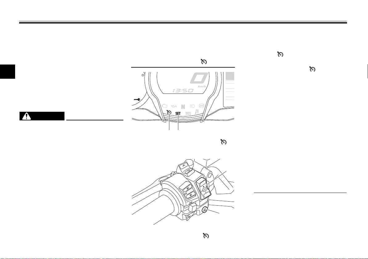
sure that the cruise control system indicator light “ ” is off.
A.TEM
C.TEM
TIME T
1. Cruise control system indicator light “ ”
2. Cruise control setting indicator light “SET”
RES
SET
PASS
1. Cruise control setting switch “RES+/SET–”
2. Cruise control power switch “ ”
3-7
Activating and setting the cruise
control system
1. Push the cruise control power
switch “ ” located on the left
handlebar. The cruise control system indicator light “ ” will come
on.
2. Push the “SET–” side of the cruise
control setting switch to activate
the cruise control system. Your
current traveling speed will become the set cruising speed. The
cruise control setting indicator
light “SET” will come on.
Adjusting the set cruising speed
While the cruise control system is operating, push the “RES+” side of the
cruise control setting switch to increase the set cruising speed or the
“SET–” side to decrease the set speed.
Pushing the setting switch once will
change the speed in increments of approximately 2.0 km/h (1.2 mi/h). Holding the “RES+” or “SET–” side of the
INSTRUMENT AND CONTROL FUNCTIONS
TIP
WARNING
TIP
2 1
cruise control setting switch down will
increase or decrease the speed continuously until the switch is released.
You can also manually increase your
traveling speed using the throttle. After
you have accelerated, you can set a
new cruising speed by pushing the
“SET–” side of the setting switch. If you
do not set a new cruising speed, when
you return the throttle grip, the vehicle
will decelerate to the previously set
cruising speed.
Deactivating the cruise control system
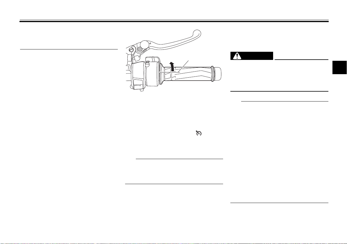
Perform one of the following operations to cancel the set cruising speed.
The “SET” indicator light will go off.
Turn the throttle grip past the
closed position in the deceleration
direction.
1. Closed position
2. Cruise control cancel direction
Apply the front or rear brake.
Disengage the clutch.
Push the power switch to turn off the
cruise control system. The “ ” indicator light and the “SET” indicator light
will go off.
Traveling speed decreases as soon as
the cruise control system is deactivated; unless the throttle grip is turned.
Using the resume function
Push the “RES+” side of the cruise
control setting switch to reactivate the
cruise control system. The traveling
speed will return to the previously set
cruising speed. The “SET” indicator
light will come on.
EWA16351
It is dangerous to use the resume
function when the previously set
cruising speed is too high for current
conditions.
The resume function operates
when riding in 3rd gear at speeds
between about 50 km/h (31 mi/h)
and 160 km/h (100 mi/h), or 4th or
5th gear at speeds between about
50 km/h (31 mi/h) and 180 km/h
(112 mi/h).
Pushing the power switch while
the system is operating will turn
the system off completely and
erase the previously set cruising
speed. You will not be able to use
the resume function until a new
cruising speed has been set.
3
3-8
INSTRUMENT AND CONTROL FUNCTIONS
TIP
1 2 3 4
Automatic deactivation of the cruise
control system
The cruise control system for this model is electronically controlled and is
linked with the other control systems.
The cruise control system will auto-
3
matically become deactivated under
the following conditions:
The cruise control system is not
able to maintain the set cruising
speed.
Wheel slip or wheel spin is detect-
ed. (If the traction control system
has not been turned off, the traction control system will work.)
The start/engine stop switch is set
to the “ ” position.
The engine stalls.
The sidestand is lowered.
When traveling with a set cruising
speed, if the cruise control system is
deactivated under the above conditions, the “ ” indicator light will go off
and the “SET” indicator light will flash
for 4 seconds, and then go off.
When not traveling with a set cruising
speed, if the start/engine stop switch is
set to the “ ” position, the engine
stalls, or the sidestand is lowered, then
the “ ” indicator light will go off (the
“SET” indicator light will not flash).
If the cruise control system is automatically deactivated, please stop and
confirm that your vehicle is in good operating condition.
Before using the cruise control system
again, activate it using the power
switch.
In some cases, the cruise control system may not be able to maintain the set
cruising speed when the vehicle is
traveling uphill or downhill.
When the vehicle is traveling up-
hill, the actual traveling speed may
become lower than the set cruising speed. If this occurs, accelerate to the desired traveling speed
using the throttle.
When the vehicle is traveling
downhill, the actual traveling
speed may become higher than
the set cruising speed. If this occurs, the setting switch cannot be
used to adjust the set cruising
speed. To reduce the traveling
speed, apply the brakes. When
the brakes are applied, the cruise
control system will become deactivated.
Self-diagnosis device
GEAR
N
A.TEMP ˚C
25
C.TEMP ˚C
Lo
TIME TRIP
0:06
1. Engine trouble warning light “ ”
2. Cruise control system indicator light “ ”
3. Cruise control setting indicator light “SET”
4. Error code display
The cruise control system will also become deactivated when an irregularity
with any of the vehicle systems is detected. The “SET” indicator light will go
off and the “ ” indicator light will
flash. You will not be able to use the
cruise control system while the engine
3-9
INSTRUMENT AND CONTROL FUNCTIONS
WARNING
NOTICE
WARNING
TIP
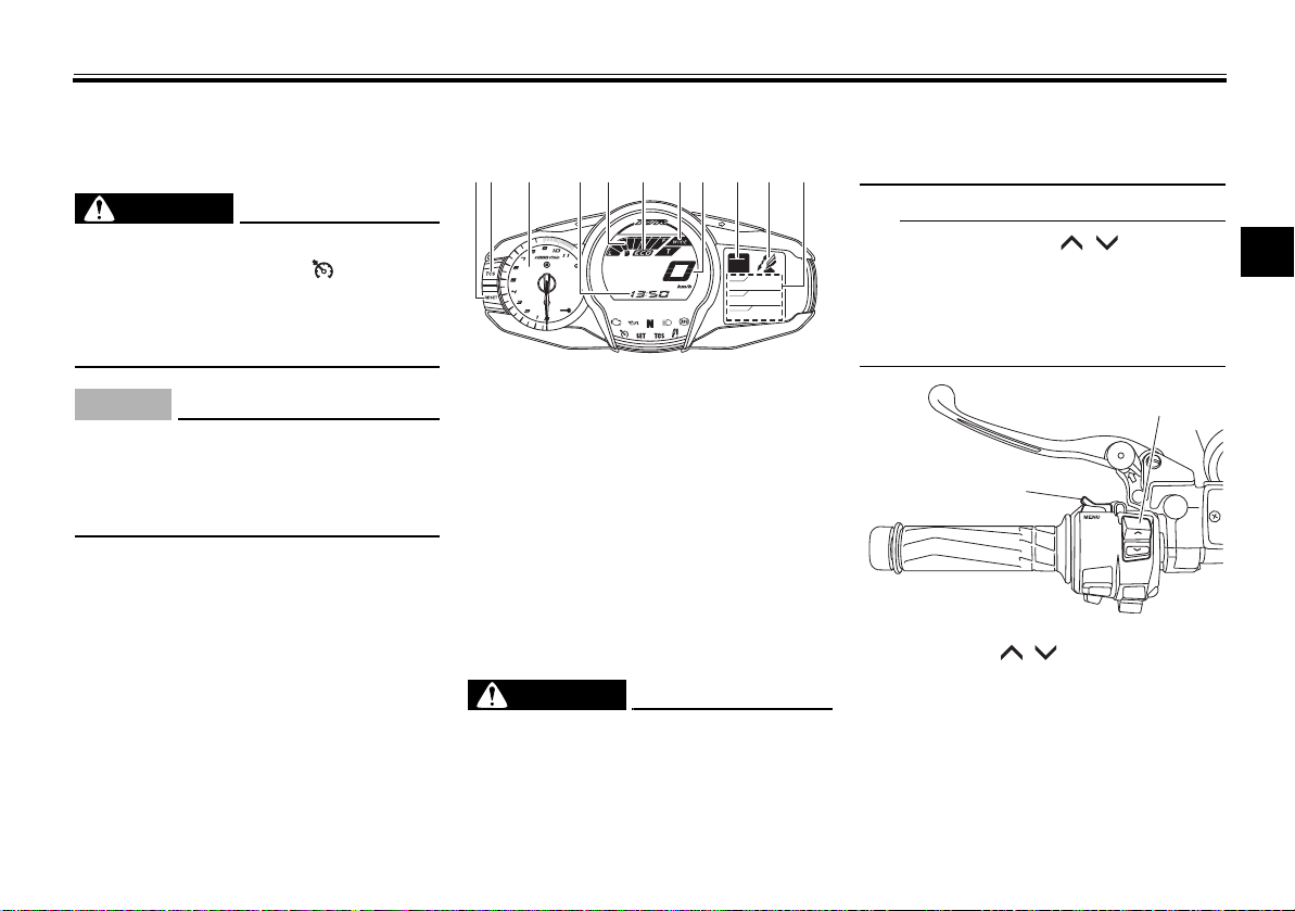
12 3 114 5 876 9 10
1
2
trouble warning light is on, or while the
cruise control system is malfunctioning.
If the cruise control system is not
working correctly, the “ ” indicator
light will flash. If this occurs, turn the
cruise control system off and have a
Yamaha dealer check it.
If the display indicates an error
code, the vehicle should be checked
as soon as possible in order to avoid
engine damage.
EWA16361
ECA11591
EAU58233
Multi-function meter unit
GEAR
N
A.TEMP ˚C
25
C.TEMP ˚C
Lo
TIME TRIP
0:06
1. “RESET” button
2. “TCS” button
3. Tachometer
4. Clock
5. Fuel meter
6. Eco indicator “ECO”
7. Drive mode display
8. Speedometer
9. Transmission gear display
10.Function display
11.Information display
EWA12423
Be sure to stop the vehicle before
making any setting changes to the
multi-function meter unit. Changing
3-10
settings while riding can distract the
operator and increase the risk of an
accident.
The select switch “ / ” and the
menu switch “MENU” are located on
the left handlebar. These switches allow you to control or change the settings of the multi-function meter unit.
1. Menu switch “MENU”
2. Select switch “ / ”
The multi-function meter unit is
equipped with the following:
a speedometer
a tachometer
a clock
a fuel meter
an eco indicator
3
INSTRUMENT AND CONTROL FUNCTIONS
TIP
NOTICE
TIP
1
2
N
P
P
1
a transmission gear display
a drive mode display (which
shows the selected drive mode)
a function display (which shows
the selected function)
an information display (which
3
shows various information, such
as the odometer reading)
a setting mode display (which al-
lows you to set, select, or reset the
items shown in the information
display)
a self-diagnosis device
Be sure to turn the key to “ON” be-
fore pushing the select
switch “ / ”, menu switch
“MENU”, “RESET” button and
“TCS” button.
For the UK only: To switch the me-
ter displays between kilometers
and miles, see page 3-17.
Speedometer
The speedometer shows the vehicle’s
traveling speed.
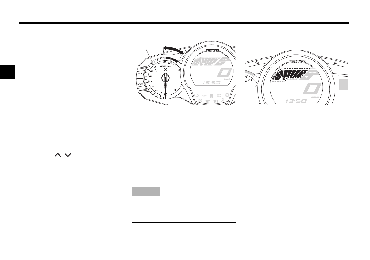
Tachometer
1. Tachometer
2. Tachometer red zone
The electric tachometer allows the rider to monitor the engine speed and
keep it within the ideal power range.
When the key is turned to “ON”, the tachometer needle sweeps once across
the r/min range and then returns to
zero r/min in order to test the electrical
circuit.
ECA10032
Do not operate the engine in the tachometer red zone.
Red zone: 9000 r/min and above
Fuel meter
GEAR
A.TEM
C.TEM
1. Fuel meter
The fuel meter indicates the amount of
fuel in the fuel tank. The display segments of the fuel meter disappear towards “E” (Empty) as the fuel level
decreases. When the last segment
starts flashing, refuel as soon as possible.
When the key is turned to “ON”, all display segments come on once in order
to test the electrical circuit.
This fuel meter is equipped with a selfdiagnosis system. If a problem is detected in the electrical circuit, all dis-
3-11
INSTRUMENT AND CONTROL FUNCTIONS
TIP
N
P
P
1
1 2
N
P
P
1
play segments start flashing. If this
occurs, have a Yamaha dealer check
the electrical circuit.
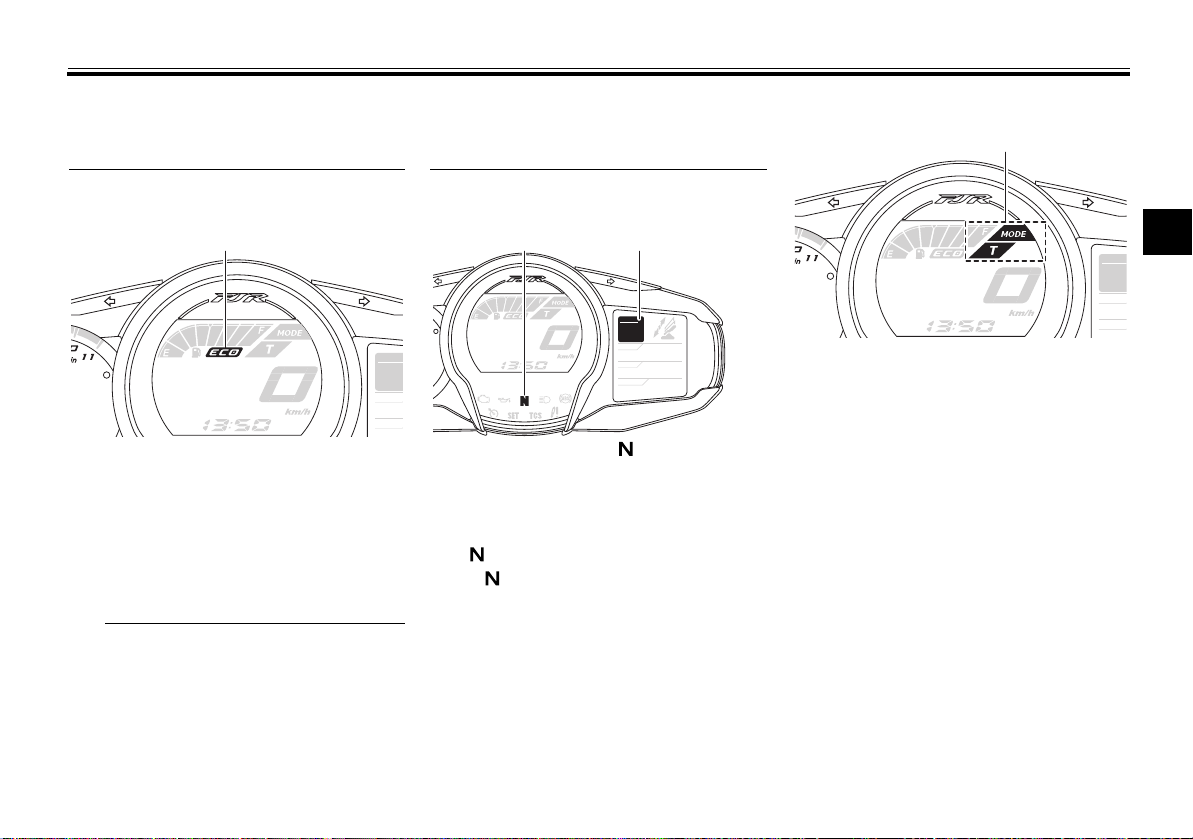
Eco indicator
GEAR
A.TEM
C.TEM
1. Eco indicator “ECO”
This indicator comes on when the vehicle is being operated in an environmentally friendly, fuel-efficient manner.
The indicator goes off when the vehicle
is stopped.
Consider the following tips to reduce
fuel consumption:
Avoid high engine speeds during
acceleration.
Travel at a constant speed.
Select the transmission gear that
is appropriate for the vehicle
speed.
Transmission gear display
GEAR
N
A.TEMP ˚C
25
C.TEMP ˚C
Lo
TIME TRIP
0:06
1. Neutral indicator light “ ”
2. Transmission gear display
This display shows the selected gear.
The neutral position is indicated
by “ ” and by the neutral indicator
light “ ”.
Drive mode display
3
GEAR
A.TEM
C.TEM
1. Drive mode display
This display indicates which drive
mode has been selected: Touring
mode “T” or sports mode “S”. For
more details on the modes and on how
to select them, see pages 3-24 and
3-26.
3-12

INSTRUMENT AND CONTROL FUNCTIONS
TIP
NOTICE
1
21 3
45
Off
Low
Middle
DisplaySetting
High
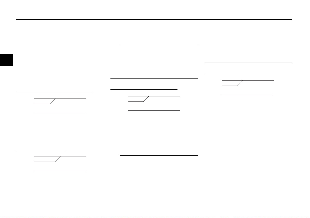
Function display Push the menu switch “MENU” to
switch the display between the following functions. The display changes
each time the switch is pushed.
GEAR
3
1. Function display
1. Grip warmer adjusting function
2. Information display selection function
3. Windshield adjusting function
4. Damping force adjusting function
5. Preload adjusting function
N
A.TEMP ˚C
C.TEMP ˚C
TIME TRIP
25
Lo
0:06
Grip warmer adjusting function
Information display selection
function
Windshield adjusting function
Damping force adjusting function
Preload adjusting function
The preload adjusting function will appear only when the vehicle is stopped
with the engine running.
The following pages contain an explanation of the grip warmer, information
display, and windshield functions. See
page 3-40 for an explanation of the
preload and damping force adjusting
functions.
Adjusting the grip warmer
This vehicle is equipped with grip
warmers, which can only be used
when the engine is running. There are 4
grip warmer settings.
To increase the grip warmer temperature, push the “ ” side of the select
switch. To decrease the grip warmer
temperature, push the “ ” side of the
select switch.
ECA17931
Be sure to wear gloves when
using the grip warmers.
If the ambient temperature is 20
°C (68 °F) or higher, do not set
the grip warmer to the high setting.
If the handlebar grip or throttle
grip becomes worn or dam-
aged, stop using the grip warmers and replace the grips.
3-13
INSTRUMENT AND CONTROL FUNCTIONS
3
421
20
ODO km
5.0
TRIP-1 km
7.0
TRIP-2 km
Selecting the information display
GEAR
N
TRIP-1 km
5.0
TRIP-2 km
7.0
GEAR
N
A.TEMP ˚C
25
C.TEMP ˚C
Lo
TIME TRIP
0:06
1. Information display
2. Display–1
3. Display–2
4. Display–3
ODO
20
km
There are 3 information displays. The
selected information display can be
switched by pushing the select switch.
The following items are shown in the
information displays:
an odometer display
tripmeter displays
a fuel reserve tripmeter display
an estimated traveling range dis-
play
an elapsed time display
an ambient temperature display
a coolant temperature display
GEAR
N
RANGE km
11
FUEL AVG km/L
12.3
CRNT FUEL
12.3
an average fuel consumption dis-
play
an instantaneous fuel consump-
tion display
The items shown in each information
display can be selected.
To set or select the items shown, see
page 3-17.
km/L
Odometer display:
Tripmeter displays:
“TRIP-1” and “TRIP-2” show the distance traveled since they were last set
to zero.
3-14
When approximately 5.5 L (1.45 US
gal, 1.21 Imp.gal) of fuel remains in the
fuel tank, the last segment of the fuel
meter starts flashing. In addition, the
information display will automatically
change to the fuel reserve tripmeter
mode “TRIP-F” and start counting the
distance traveled from that point.
GEAR
4
TRIP-F km
3.4
In that case, pushing the select switch
switches the display between the various information displays in the following order;
TRIP-F → Display–1 → Display–2 →
Display–3 → TRIP-F
To reset a tripmeter, use the select
switch to select the information display
that contains the tripmeter. Push the
3
INSTRUMENT AND CONTROL FUNCTIONS
TIP
TIP
11
RANGE km
0:06
TIME TRIP
25
A.TEMP ˚C
Lo
C.TEMP ˚C
“RESET” button briefly so that the tripmeter flashes, and then push the “RESET” button again for at least 2
seconds while the tripmeter is flashing.
If you do not reset the fuel reserve tripmeter manually, it will reset itself auto-
3
matically and the display will return to
the prior mode after refueling and traveling 5 km (3 mi).
Estimated traveling range display:
The distance that can be traveled with
the remaining fuel in the fuel tank under
the current riding conditions is shown.
Elapsed time display:
The time that has elapsed since the
key was turned to “ON” is shown. The
maximum time that can be shown is
99:59.
This display is automatically reset
when the key is turned to “OFF”.
There are also “TIME–2” and “TIME–3”
elapsed time displays, but they cannot
be set to the information display. See
“Setting mode” on page 3-17 for detailed information.
Ambient temperature display:
This display shows the ambient temperature from –9 °C to 50 °C in 1 °C increments. The temperature displayed
may vary from the ambient temperature.
–9 °C will be displayed even if the
ambient temperature falls below
–9 °C.
50 °C will be displayed even if the
ambient temperature climbs
above 50 °C.
3-15
The accuracy of the temperature
reading may be affected when riding slowly [approximately under
20 km/h (12.5 mi/h)] or when
stopped at traffic signals, railroad
crossings, etc.
Coolant temperature display:
The coolant temperature display indicates the temperature of the coolant.
The coolant temperature varies with
changes in the weather and engine
load.
If the message “Hi” flashes, stop the
vehicle, then stop the engine, and let
the engine cool. (See page 6-38.)
 Loading...