

YAMAHA F20A, F25A, F25X PARTS CATALOGUE

F20A, F25A
WORLD WIDE
USA, CANADA
F25X
290362
SERVICE MANUAL
MANUEL D’ENTRETIEN
WARTUNGSHANDBUCH
MANUAL DE SERVICIO
65W-28197-Z8-C2
E
F
D
ES

E
A20000-1
NOTICE
This manual has been prepared by the Yamaha Motor Company Ltd. primarily for use by
Yamaha dealers and their trained mechanics when performing maintenance procedures and
repairs to Yamaha equipment. It has been written to suit the needs of persons who have a
basic understanding of the mechanical and electrical concepts and procedures inherent in the
work, for without such knowledge attempted repairs or service to the equipment could render
it unsafe or unfit for use.
Because the Yamaha Motor Company, Ltd. has a policy of continuously improving its products, models may differ in detail from the descriptions and illustrations given in this publication. Use only the latest edition of this manual. Authorized Yamaha dealers are notified
periodically of modifications and significant changes in specifications and procedures, and
these are incorporated in successive editions of this manual.
A10001-0*
F20A, F25A
SERVICE MANUAL
1998 Yamaha Motor Co., Ltd.
2nd Edition, October 1998
All rights reserved.
No part of this publication may be
reproduced or transmitted in any form or
by any means including photocopying and
recording without the written permission of
the copyright holder.
Such written permission must also be
obtained before any part of this publication
is stored in a retrieval system of any nature.
Printed in Japan
P/N 65W-28197-Z8-C2

F D
ES
A20000-1
AVANT-PROPOS
Ce manuel a été préparé par la Yamaha
Motor Company principalement à
l’intention des concessionnaires Yamaha
et de leurs mécaniciens qualifiés afin de
les assister lors de l’entretien et la réparation des produits Yamaha. Ce manuel
est destiné à des personnes possédant les
connaissances de base en mécanique et
en électricité sans lesquelles l’exécution
de réparations ou d’entretiens peut rendre les machines impropres ou dangereuses à l’emploi.
La Yamaha Motor Company, Ltd.
s’efforce en permanence d’améliorer ses
produits. Par conséquent, il se peut que
les modèles diffèrent légèrement des
descriptions et illustrations de ce
manuel. Les modifications et les changements significatifs dans les caractéristiques ou les procédés sont notifiés à tous
les concessionnaires Yamaha et sont
publiés dans les éditions ultérieures de
ce manuel.
A10001-0*
F20A, F25A
MANUEL D’ENTRETIEN
1998 Yamaha Motor Co., Ltd.
2e édition, octobre 1998
Tous droits réservés.
Toute reproduction ou transmission
de ce manuel, même partielle, par
quelque procédé que ce soit, y com-
pris par photocopie ou enregistre-
ment, requiert l’accord écrit
préalable de la
Yamaha Motor Co., Ltd.
De même, l’introduction de toute
partie de ce manuel dans un système
d’archivage requiert cet accord écrit
préalable.
Imprimé au Japon
P/N 65W-28197-Z8-C2
A20000-1
HINWEIS
Dieses Handbuch wurde von der
Yamaha Motor Company, Ltd. vorrangig für Yahama-Vertragshändler
und deren qualifizierte Mechaniker
geschrieben, um sie bei der Durchführung von Wartungs- und Reparaturarbeiten an Yamaha-Motoren
zu unterstützen. Es werden Grundkenntnisse der mechanischen und
elektrischen Wirkungsweise und
der Arbeitsverfahren vorausgesetzt, denn ohne diese Grundkenntnisse versuchte Wartungs- und
Reparaturarbeiten machen das Produkt eher unsicher oder sogar
gebrauchsunfähig.
Die Yamaha Motor Company, Ltd.
ist stets bestrebt, ihre Produkte
ständig zu verbessern. Einzelne
Modelle können im Detail von den
hier enthaltenen Beschreibungen
und Abbildungen abweichen.
Benutzen Sie immer nur die neueste Ausgabe dieses Handbuchs.
Autorisierte Yamaha-Vertragshändler werden regelmäßig vorab
über Modifikationen und wesentliche Änderungen der technischen
Daten und Verfahren unterrichtet,
die in der jeweils nächsten Ausgaben dieses Handbuchs eingearbeitet werden.
A10001-0*
F20A, F25A
WARTUNGSHANDBUCH
1998 Yamaha Motor Co., Ltd.
2. Ausgabe, Oktober 1998
Alle Rechte vorbehalten.
Diese Veröffentlichung darf auch
teilweise in keiner Weise oder
durch irgendein Verfahren ohne
die schriftlichts Genehmigung
des Urheberrechts-Inhabers
reproduziert oder übertragen
werden. Dies gilt auch für Foto-
kopien und Aufzeichnungen. Die
schriftliche Genehmigung ist vor
der Übernahme in irgendein
Informationssystem einzuholen.
Gedruckt in Japan
P/N 65W-28197-Z8-C2
A20000-1
AVISO
Este manual ha sido preparado por
Yamaha Motor Company Ltd. principalmente para que lo empleen los concesionarios Yamaha y sus mecánicos
cualificados al llevar a cabo los procedimientos de mantenimiento y de reparación de los equipos Yamaha. Se ha
escrito para adaptarlo a las necesidades
de las personas que ya tienen un conocimiento básicos de los conceptos mecánicos y eléctricos y de los procedimientos
inherentes al trabajo, porque sin tales
conocimientos las reparaciones o el servicio del equipo podría dejar el equipo
inseguro o inadecuado para la utilización.
Puesto que Yamaha Motor Company,
Ltd. sigue una política de mejora continua de sus productos, los modelos pueden diferir en detalles de las
descripciones e ilustraciones dadas en
esta publicación. Emplee sólo la última
edición de este manual. Se notifica
periódicamente a los concesionarios
autorizados Yamaha sobre las modificaciones y cambios importantes en las
especificaciones y procedimientos, y
tales cambios se incorporan en las ediciones subsiguientes de este manual.
A10001-0*
F20A, F25A
MANUAL DE SERVICIO
1998 Yamaha Motor Co., Ltd.
2ª Edición, octubre 1998
Reservados todos los derechos.
Queda prohibida la reproducción o
transmisión de esta publicación, ya
sea en su totalidad o en parte, y por
cualquier medio, incluido su fotoco-
piado o grabación, sin el consenti-
miento por escrito del titular del
derecho de copyright. También
deberá obtenerse este consentimiento antes de proceder al almacenamiento de cualquier parte de esta
publicación en un sistema de bús-
queda documental de cualquier natu-
raleza.
Impreso en Japón
P/N˚ 65W-28197-Z8-C2

E
HOW TO USE THIS MANUAL
MANUAL FORMAT
All of the procedures in this manual are organized in a sequential, step-by-step format. The
information has been compiled to provide the mechanic with an easy to read, handy reference that contains comprehensive explanations of all disassembly, repair, assembly, and
inspection operations.
In this revised format, the condition of a faulty component will precede an arrow symbol and
the course of action required will follow the symbol, e.g.,
Bearings
●
Pitting/scratches → Replace.
To assist you in finding your way through this manual, the section title and major heading is
given at the top of every page.
ILLUSTRATIONS
The illustrations within this service manual represent all of the designated models.
CROSS REFERENCES
The cross references have been kept to a minimum. Cross references will direct you to the
appropriate section or chapter.

F D
ES
STRUCTURE DU
MANUEL
FORMAT DU MANUEL
Tous les procédés repris dans ce manuel
sont décrits pas à pas. Les informations
ont été condensées pour fournir au mécanicien un guide pratique et facile à lire,
contenant des explications claires pour
tous les procédés de démontage, de réparation, de remontage et de vérification.
L’état d’une pièce défectueuse est mentionné et est suivi d’une flèche et de la
mesure à prendre pour chaque symptôme
décelé. Ainsi, par exemple:
●
Roulements
Piqûres/endommagements →
Remplacer.
Pour plus de facilité, le nom du chapitre
et les titres principaux figurent à l’entête de chaque page.
ILLUSTRATIONS
Les illustrations représentent les modèles désignés.
RENVOIS
Les renvois ont été évités au maximum.
Les renvois réfèrent à la section ou au
chapitre appropriés.
BENUTZUNG DIESES
HANDBUCHS
AUFBAU
Alle in diesem Handbuch enthaltenen Verfahren sind in der richtigen
Reihenfolge Schritt für Schritt
beschrieben. Die Informationen
wurden so aufbereitet, daß dem
Mechaniker in leicht verständlicher, handlicher Form alle notwendigen Handgriffe beim
Zerlegen, bei der Reparatur und
dem Zusammenbau sowie bei der
Inspektion ausführlich erklärt werden.
Bei dieser neuen Darstellungsweise folgt nach der Zustandsbeschreibung eines schadhaften
Teils ein Pfeil, der auf die notwendige Aktion hinweist, z.B:
●
Lager
Lochfraß/Kratzer → Ersetzen.
Die Abschnittstitel finden sich zur
Bezugnahme in der Kopfzeile wieder.
ABBILDUNGEN
Die Abbildungen in diesem Wartungshandbuch gelten für alle
angegebenen Modelle.
QUERVERWEISE
Querverweise wurden auf ein
Minimum beschränkt. Querverweise führen Sie zum entsprechenden Abschnitt oder Kapitel.
CÓMO EMPLEAR ESTE
MANUAL
FORMATO DEL MANUAL
Todos los procedimientos de este
manual están organizados en un formato
de paso a paso secuencial. La información ha sido compilada para proporcionar al mecánico una referencia útil y de
fácil lectura que contiene detalladas
explicaciones de todas las operaciones
de desmontaje, reparación, montaje e
inspección.
En este formato revisado, el estado de un
componente averiado irá seguido de un
símbolo de flecha y de la acción requerida detrás de la fecha, por ejemplo:
●
Cojinetes
Picadas/rayadas → Reemplazar.
Para ayudarle a encontrar lo que busca
en este manual, el título de la sección y
el encabezamiento principal se incluye al
principio de cada página.
ILUSTRACIONES
Las ilustraciones de este manual de servicio representan a todos los modelos
designados.
REFERENCIAS DE CONSULTA
Las referencias de consulta se han manteniendo al mínimo. Estas referencias
indican la sección o capítulo que debe
consultarse.

E
IMPORTANT INFORMATION
In this Service Manual particularly important information is distinguished in the following
ways.
The Safety Alert Symbol means ATTENTION! BECOME ALERT! YOUR SAFETY IS
INVOLVED!
WARNING
Failure to follow WARNING instructions could result in severe injury or death to the machine
operator, a bystander, or a person inspecting or repairing the outboard motor.
CAUTION:
A CAUTION indicates special precautions that must be taken to avoid damage to the outboard motor.
NOTE:
A NOTE provides key information to make procedures easier or clearer.

F D
N
ES
INFORMATIONS IMPORTANTES
Les informations particulièrement
importantes sont repérées par les notations suivantes.
Le symbole d’alerte sécurité signifie
ATTENTION! SOYEZ ATTENTIF!
VOTRE SECURITE EST MENACEE!
AVERTISSEMENT
Le non-respect d’une instruction
AVERTISSEMENT peut blesser ou
entraîner la mort de l’opérateur, d’un
passager ou d’une personne inspectant
ou réparant le moteur hors-bord.
ATTENTION:
ATTENTION indique les consignes
qui doivent être respectées afin d’évi-
ter d’endommager le moteur horsbord.
.B.:
N.B. donne des informations importantes qui facilitent et expliquent les différentes opérations.
WICHTIGE INFORMATION
Informationen in diesem Wartungshandbuch, die von besonderer Wichtigkeit sind, werden auf
eine der folgenden Arten hervorgehoben.
Dieses Warnsymbol bedeutet:
VORSICHT! ES GEHT UM IHRE
SICHERHEIT!
WARNUNG
Eine WARNUNG enthält Anweisungen, die eingehalten werden
müssen, um Verletzungen, möglicherweise sogar mit Todesfolge,
für Bediener, in der Nähe befindliche Personen oder Techniker, die
Inspektionen oder Reparaturen
an Außenbordmotoren vornehmen, zu vermeiden.
ACHTUNG:
Unter ACHTUNG finden Sie spezielle Vorsichtsmaßnahmen, die
eingehalten werden müssen, um
Beschädigungen am Außenbordmotor zu vermeiden.
INFORMACIÓN IMPORTANTE
En este manual de servicio, la información particularmente importante se distingue según se indica a continuación.
El símbolo de alerta de seguridad
significa ¡ATENCION, ESTA EN
JUEGO SU PROPIA SEGURIDAD!
ATENCION
El incumplimiento de este tipo de instrucciones de ATENCION puede causar graves lesiones, e incluso la
muerte, al operador del motor, a las
personas a su alrededor o al técnico
que inspeccione o repare el motor
fuera de borda.
PRECAUCION:
Una instrucción de PRECAUCION
indica precauciones especiales que
debe observar para evitar dañar el
motor fuera de borda.
NOTA:
La NOTA proporciona información
clave que facilita o clarifica determinados procedimientos.
HINWEIS:
Ein HINWEIS enthält Informationen, die einen Vorgang einfacher
oder deutlicher machen.
1
2
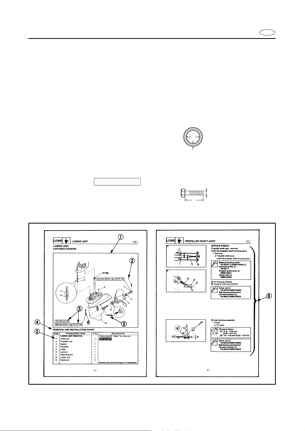
HOW TO USE THIS MANUAL
To help identify parts and clarify procedure steps, there are exploded diagrams at the
start of each removal and disassembly section.
Numbers are given in the order of the jobs in the exploded diagram. A circled number
indicates a disassembly step.
3
Symbols indicate parts to be lubricated or replaced (see “SYMBOLS”).
4
A job instruction chart accompanies the exploded diagram, providing the order of jobs,
names of parts, notes in jobs, etc.
Example:
O-ring size 39.5 × 2.5 mm: Inside diameter (D) × Ring diameter (d)
D
E
d
5
Dimension figures and the number of parts, are provided for fasteners that require a tightening torque.
Example:
Bolt or screw size : M10 (D) × 25 mm (L) (2 pieces)
6
Jobs requiring more information (such as special tools and technical data) are described
10 × 25 mm (2)
D
L
sequentially.

F D
10 × 25 mm (2)
1
ES
ORGANISATION DES
INFORMATIONS
1
Chaque section de dépose et de
démontage est précédée de vues en
éclaté rendant plus faciles les étapes
du travail et l’identification des piéces.
2
Sur les vues en éclaté, les pièces sont
numérotées dans l’ordre des opérations à effectuer. Un chiffre entouré
d’un cercle correspond à une étape
de démontage.
3
Des symboles repèrent les pièces à
lubrifier ou à remplacer (se reporter
à “SYMBOLES”).
4
Un tableau accompagne les vues en
éclaté. Celui-ci reprend les travaux à
effectuer et l’ordre dans lequel il faut
les effectuer, ainsi que le nom des
pièces et certaines remarques utiles.
Exemple:
Taille de joint torique
39,5 × 2,5 mm: diamètre intérieur
(D) × diamètre du joint (d)
5
Les dimensions ainsi que le nombre
requis sont indiqués pour les vis et
les boulons devant être serrés au
couple.
Exemple:
Taille de boulon ou de vis
10 × 25 mm (2)
(L) (2 pièces)
6
Les travaux nécessitant des explications supplémentaires (p. ex. outils
spéciaux et données techniques) sont
expliqués pas à pas.
: M10 (D) × 25 mm
BENUTZUNG DIESES
HANDBUCHS
1
Um Teile besser aufzufinden
und einzelne Schritte eines
Verfahrens klarer zu machen,
befindet sich zu Beginn jedes
Ausbau- und ZerlegungAbschnitts eine Explosionszeichnung.
2
Die in der Explosionszeichnung
angegebenen Ziffern entsprechen der Reihenfolge der
Arbeitsschritte. Eine eingekreiste Nummer bezeichnet einen
Arbeitsschritt der Zerlegung.
3
Zu schmierende oder zu ersetzende Teile sind durch Symbole gekennzeichnet (näheres
siehe “SYMBOLE”).
4
Nach der Explosionszeichnung
folgt eine tabellarische Aufstellung der Arbeitsschritte, diese
gibt die Reihenfolge der einzelnen Schritte, die Bezeichnungen der Teile, Hinweise zu
einzelnen Schritten usw. an.
Beispiel:
O-Ring-Größe 39,5 × 2,5 mm:
Innendurchmesser (D) × Ringdurchmesser (d)
5
Für Schrauben und Muttern,
die mit einem vorgeschriebenen Moment angezogen werden müssen, sind Maßbilder
und die Teilnummern angegeben.
Beispiel:
Schranbengröße
10 × 25 mm (2)
25 mm (L) (2 Stück)
: M10 (D) ×
CÓMO EMPLEAR ESTE MANUAL
Para ayudarle a identificar las partes
y para clarificar los pasos de los pro-
cedimientos, encontrará diagramas
detallados al principio de cada sec-
ción de extracción y desmontaje.
2
Se dan números en el orden de las
tareas en el diagrama detallado. Un
número dentro de un círculo indica
un paso de desmontaje.
3
Los símbolos indican las partes que
deben lubricarse o reemplazarse
(Vea el apartado de “SÍMBOLOS”).
4
El diagrama detallado viene acompa-
ñado de una gráfica de instrucciones
de la tarea que indica el orden de la
tarea, los nombres de las partes, las
botas sobre las tareas, etc.
Ejemplo:
Tamaño de la junta tórica
39,5 × 2,5 mm; Diámetro interior
(D) × Diámetro de la junta (d)
5
Los valores de dimensiones y los
números de parte se dan para los fija-
dores que requieren una torsión de
apriete.
Ejemplo:
Tamaño del perno o tornillo
: M10 (D) × 25 mm
(L) (2 piezas)
6
Las tareas que requieren más infor-
mación (tales como herramientas
especiales y datos técnicos) se des-
criben de forma secuencial.
6
Arbeiten, die eine ausführlichere Beschreibung brauchen
(z.B. Spezialwerkzeuge, technische Daten) werden Schritt für
Schritt beschrieben.
1
2
3
4
5
6
7
8
9
0
A
B
C
D
E
F
G
H
E
12
GEN
INFO
34
SPEC
INSP
FUEL
ADJ
56
POWR
78
BRKT
90
LOWR
–+
ELEC
TRBL
ANLS
AB
A50001-1-4
SYMBOLS
Symbols 1 to 9 are designed as thumbtabs to indicate the content of a chapter.
General information
Specifications
Periodic inspection and adjustment
Fuel system
Power unit
Lower unit
Bracket unit
Electrical systems
Trouble-analysis
Symbols 0 to E indicate specific data:
Special tool
Specified liquid
Specified engine speed
Specified torque
Specified measurement
Specified electrical value
[Resistance ( Ω ), Voltage (V), Electric current
(A)]
CD
T
.
R
.
EF
E
GH
A
IJ
GM
KL
LT
271
MN
LT
572
M
LT
242
SS
LT
4
Symbol F to H in an exploded diagram
indicate the grade of lubricant and the location of the lubrication point:
Apply Yamaha 2-stroke outboard motor oil
Apply water resistant grease
(Yamaha grease A, Yamaha marine grease)
Apply molybdenum disulfide oil
Symbols I to N in an exploded diagram
indicate the grade of the sealing or locking
agent and the location of the application
point:
I Apply Gasket Maker
J Apply Yamabond #4
(Yamaha bond number 4)
K Apply LOCTITE No. 271 (Red LOCTITE)
L Apply LOCTITE No. 242 (Blue LOCTITE)
M Apply LOCTITE No. 572
N Apply silicon sealant

F D
ES
1
2
3
4
A50001-1-4
SYMBOLES
Les symboles 1 à 9 servent d’onglets
et indiquent le contenu des différents
chapitres:
Informations générales
Spécifications
Inspection périodique et réglage
Système d’alimentation
5 Moteur
6 Bloc de propulsion
7 Unité de support
8 Equipement électrique
9 Dépannage
Les symboles 0 à E apportent certaines
précisions:
0 Outillage spécial
A Liquide spécifié
B Vitesse du moteur spécifiée
C Couple spécifié
D Mesure spécifiée
E Valeur électrique spécifiée
[résistance (Ω), tension (V),
courant électrique (A)]
Les symboles F à H dans les vues en
éclaté donnent la qualité de lubrifiant à
employer et les points de graissage:
F Appliquer de l’huile moteur deux temps
Yamaha pour hors-bord.
G Appliquer de la graisse hydrofuge (graisse
Yamaha A, graisse Yamaha marine).
H Appliquer de l’huile au bisulphure de
molybdène.
Les symboles I à N dans les vues en
éclaté indiquent la qualité des liquides
d’étanchéité et de l’agent bloquant à
employer ainsi que les points d’application:
I Appliquer du Gasket marker.
J Appliquer du Yamabond n˚4
K Appliquer du LOCTITE
(LOCTITE rouge)
L Appliquer du LOCTITE n˚ 242
(LOCTITE bleu)
M Appliquer du LOCTITE n˚ 572
N Appliquer une pâte d’étanchéité au
silicone.
n˚ 271
A50001-1-4
SYMBOLE
Die Symbole 1 bis 9 sind Randmarkierungen, die auf den Inhalt
der einzelnen Kapitel hinweisen.
1 Allgemeines
2 Technische Daten
3 Regelmäßige Inspektionen und Ein-
stellungen
4 Kraftstoffanlage
5 Motor
6 Antriebseinheit
7 Motorhalterung
8 Elektrische Anlage
9 Störungssuche
Die Symbole 0 bis E zeigen spezifische Daten an:
0 Spezialwerkzeug
A Spezielle Flüssigkeit
B Vorgeschriebene Motordrehzahl
C Schrauben-Anzugsmoment
D Spezielle Messung
E Elektrischer Meßwert
[Widerstand (Ω), Spannung (V),
Stromstärke (A)]
Die Symbole F bis H zeigen in
einer Explosionszeichnung den
Schmiermitteltyp und die
Schmierstelle an:
F Yamaha-Zweitaktöl für Außenbor-
der auftragen
G Wasserfestes Fett auftragen
(Yamaha-Fett A, Yamaha-Bootsfett)
H Molybdänsulfid-Öl auftragen
Die Symbole I bis N zeigen in
einer Explosionszeichnung den
Typ des Dichtungsmittels oder
Klebers und die Anwendungsstelle
an.
I Gasket maker auftragen
J Yamabond #4 auftragen
(Yamaha Klebstoff Nr. 4)
K LOCTITE
auftragen
L LOCTITE Nr. 242 (blaues LOCTITE)
auftragen
M LOCTITE
N Silikon-Dichtungsmasse auftragen
Nr. 271 (rotes LOCTITE)
Nr. 572 auftragen
A50001-1-4
SÍMBOLOS
Los símbolos 1 a 9 identifican el contenidos de un capítulo.
1 Información general
2 Especificaciones
3 Inspección periódica y ajuste
4 Sistema de combustible
5 Motor
6 Unidad inferior
7 Unidad de ménsula
8 Sistemas eléctricos
9 Análisis de averías
Los símbolos 0 a E indican datos específicos:
0 Herramienta especial
A Líquido especificado
B Velocidad del motor especificada
C Torsión especificada
D Medición especificada
E Valor eléctrico especificado
[Resistencia (Ω), Tensión (V),
Corriente eléctrica (A)]
Los símbolos F a H de un diagrama
detallado indican el grado de lubricante
y la situación del punto de lubricación:
F Aplicar aceite de motor de fuera de borda
de 2 tiempos Yamaha
G Aplicar grasa hidrófuga Yamaha (grasa
náutica A Yamaha, grasa náutica
Yamaha)
H Aplicar aceite con bisulfuro de molibdeno
Los símbolos I a N de un diagrama
detallado indican el grado de la junta
líquida o compuesto obturante y la situación del punto de aplicación:
I Aplicar empaquetadura líquida de marca
J Aplique agente adhesivo Yamabond N.˚ 4
K Aplicar LOCTITE
(LOCTITE rojo)
L Aplicar LOCTITE
(LOCTITE azul)
M Aplicar LOCTITE
N Aplique agente de sellado silicónico
N.˚ 271
N.˚ 242
N.˚ 572

E
A30000-0
INDEX
GENERAL INFORMATION
SPECIFICATIONS
PERIODIC INSPECTION AND
ADJUSTMENT
FUEL SYSTEM
POWER UNIT
LOWER UNIT
BRACKET UNIT
ELECTRICAL SYSTEM
TROUBLE-ANALYSIS
F D
–+
ES
A30000-0
TABLE DES
MATIERES
INFORMATIONS
GENERALES
SPECIFICATIONS
INSPECTION
PERIODIQUE ET
REGLAGE
A30000-0
ALLGEMEINES
TECHNISCHE
DATEN
REGELMÄßIGE
INSPEKTIONEN UND
EINSTELLUNGEN
INHALT
A30000-0
INFORMACIÓN
GENERAL
ESPECIFICACIONES
INSPECCIÓN
PERIÓDICA Y
AJUSTE
INDICE
GEN
INFO
SPEC
INSP
ADJ
1
2
3
SYSTEME
D’ALIMENTATION
MOTEUR
BLOC DE
PROPULSION
UNITE DE SUPPORT
KRAFTSTOFFANLAGE
MOTOR
ANTRIEBSEINHEIT
MOTORHALTERUNG
SISTEMA DE
COMBUSTIBLE
MOTOR
UNIDAD INFERIOR
UNIDAD DE
MÉNSULA
FUEL
POWR
LOWR
BRKT
4
5
6
7
EQUIPEMENT
ELECTRIQUE
DEPANNAGE
ELEKTRISCHE
ANLAGE
STÖRUNGSSUCHE
SISTEMAS
ELÉCTRICOS
ANÁLISIS DE
AVERÍAS
ELEC
TRBL
ANLS
8
9

GEN
INFO
CHAPTER 1
GENERAL INFORMATION
IDENTIFICATION .............................................................................................1-1
SERIAL NUMBER .....................................................................................1-1
STARTING SERIAL NUMBERS ...............................................................1-1
E
SAFETY WHILE WORKING
FIRE PREVENTION ...................................................................................1-2
VENTILATION...........................................................................................1-2
SELF-PROTECTION ..................................................................................1-2
OILS, GREASES AND SEALING FLUIDS ................................................1-2
GOOD WORKING PRACTICES ................................................................1-3
DISASSEMBLY AND ASSEMBLY ...........................................................1-4
SPECIAL TOOLS
MEASURING ............................................................................................1-5
REMOVAL AND INSTALLATION.............................................................1-7
.............................................................................................1-5
............................................................................1-2

F D
ES
CHAPITRE 1
INFORMATIONS
GENERALES
IDENTIFICATION .............................1-1
NUMERO DE SERIE........................1-1
DEBUT DE NUMEROS
DE SERIE.........................................1-1
MESURES DE SECURITE ................1-2
MESURES DE SECURITE
CONTRE LES INCENDIES ............1-2
AERATION .......................................1-2
PROTECTION...................................1-2
HUILES, GRAISSES ET LIQUIDES
D’ETANCHEITE .............................1-2
NOTES CONCERNANT
L’OUTILLAGE ET LES PIECES... 1-3
DEMONTAGE ET
REMONTAGE .................................1-4
OUTILLAGE SPECIAL .....................1-5
MESURAGE .....................................1-5
DEPOSE ET INSTALLATION ........1-7
KAPITEL 1
ALLGEMEINES
IDENTIFIZIERUNG .........................1-1
SERIENNUMMER.......................1-1
ANFANGSNUMMERN
DER SERIE .................................1-1
SICHERHEITSMASSNAHMEN ......1-2
BRANDSCHUTZ .........................1-2
BELÜFTUNG...............................1-2
SELBSTSCHUTZ.........................1-2
ÖLE, SCHMIERSTOFFE UND
DICHTUNGSMITTEL .................1-2
RICHTIGE
ARBEITSGEWOHNHEITEN.......1-3
ZERLEGUNG UND
ZUSAMMENBAU ......................1-4
SPEZIALWERKZEUGE ...................1-5
MESSEN .....................................1-5
AUSBAU UND EINBAU .............1-7
CAPITULO 1
INFORMACIÓN
GENERAL
IDENTIFICACION .............................1-1
NUMERO DE SERIE........................1-1
NUMEROS INICIALES
DE SERIE.........................................1-1
SEGURIDAD EN EL TRABAJO ......1-2
PREVENCION
DE INCENDIOS ..............................1-2
VENTILACION ................................1-2
AUTOPROTECCION .......................1-2
ACEITES, GRASAS Y LIQUIDOS
OBTURANTES................................1-2
PROCEDIMIENTOS DE TRABAJO
CORRECTOS...................................1-3
DESMONTAJE Y MONTAJE..........1-4
HERRAMIENTAS ESPECIALES .... 1-5
MEDICION .......................................1-5
EXTRACCION E
INSTALACION ...............................1-7
1
2
3
4
5
6
7
8
9
1
2
3
4
GEN
INFO
IDENTIFICATION
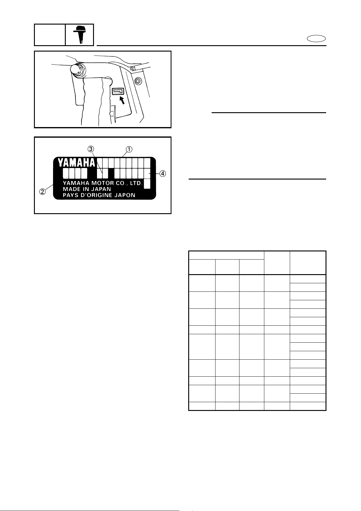
A60000-1*
IDENTIFICATION
SERIAL NUMBER
The of the outboard motor’s serial number
is stamped on a label which is attached to
the port side of the clamp bracket.
NOTE:
For USA model:
As an antitheft measure, a special label on
which the outboard motor’s serial number
is stamped is bonded to the port side of the
clamp bracket. The label is specially treated
so that peeling it off causes cracks across
the serial number.
E
Model name
Approved model code
Transom height
Serial number
STARTING SERIAL NUMBERS
The starting serial number blocks are as follows:
Model name
World-
wide
F20AMH — — 65W
F20AEH — — 65W
F20AE — — 65W
F20AET — — 65W L: 600428 ~
F25AMH F25MH F25MH 65W
F25AEH F25EH — 65W
F25AEHT — F25TH 65W L: 450355 ~
F25AE F25ER — 65W
F25AET F25TR F25TR 65W L: 401032 ~
USA CANADA
Approval
model
code
Starting
serial
number
S: 650101 ~
L: 750101 ~
S: 700101 ~
L: 800101 ~
S: 100412 ~
L: 500101 ~
S: 150101 ~
L: 250101 ~
X: 550101 ~
S: 050503 ~
L: 350865 ~
S: 000183 ~
L: 300756 ~
1-1

F D
N
1
2
3
4
1
2
3
4
1
2
3
4
IDENTIFICATION
GEN
INFO
A60000-1*
IDENTIFICATION
NUMERO DE SERIE
Le numéro de série du moteur hors-bord
est poinçonné sur une étiquette collée au
côté bâbord de la presse.
.B.:
Modèle pour les E.-U.
Le numéro de série du moteur figure sur
une étiquette spéciale antivol qui est
apposée au côté bâbord. Cette étiquette
est conçue de sorte qu’elle se fendille à
l’endroit du numéro de série quand on
tente de la décoller.
Nom du modèle
Numéro de modèle approuvé
Hauteur de barre d’arcasse
Numéro de série
DEBUT DE NUMEROS DE SERIE
Les blocs de début de numéros de série
sont les suivants:
Nom du modèle N˚ de
Universel E.-U. Canada
F20AMH — — 65W
F20AEH — — 65W
F20AE — — 65W
F20AET — — 65W L: 600428 ~
F25AMH F25MH F25MH 65W
F25AEH F25EH — 65W
F25AEHT — F25TH 65W L: 450355 ~
F25AE F25ER — 65W
F25AET F25TR F25TR 65W L: 401032 ~
approuvé
IDENTIFIZIERUNG
IDENTIFICACION
modèle
Premier
numéro de
série
S: 650101 ~
L: 750101 ~
S: 700101 ~
L: 800101 ~
S: 100412 ~
L: 500101 ~
S: 150101 ~
L: 250101 ~
X: 550101 ~
S: 050503 ~
L: 350865 ~
S: 000183 ~
L: 300756 ~
A60000-1*
IDENTIFIZIERUNG
SERIENNUMMER
Die Seriennummer des Außenbordmotors ist im Typenschild auf
der Backbordseite der Motorhalterung eingeschlagen.
HINWEIS:
Für USA-Modelle
Zur Diebstahlsicherung ist eine
spezielle Plakette mit der aufgestempelten Seriennummer des
Außenbordmotors auf die Backbordseite geklebt. Die Plakette ist
spezialbehandelt, so daß bei der
Ablösung Risse in der Seriennummer entstehen.
Modellbezeichnung
Zugelassene Modellnummer
Spiegelhöhe
Seriennummer
ANFANGSNUMMERN DER SERIE
Die Seriennummern-Blöcke beginnen mit folgenden Anfangsnummern:
Modellbezeichnung
Weltweit USA Kanada
F20AMH — — 65W
F20AEH — — 65W
F20AE — — 65W
F20AET — — 65W L: 600428 ~
F25AMH F25MH F25MH 65W
F25AEH F25EH — 65W
F25AEHT — F25TH 65W L: 450355 ~
F25AE F25ER — 65W
F25AET F25TR F25TR 65W L: 401032 ~
Modell-
Code
Anfangs-
nummer
der Serie
S: 650101 ~
L: 750101 ~
S: 700101 ~
L: 800101 ~
S: 100412 ~
L: 500101 ~
S: 150101 ~
L: 250101 ~
X: 550101 ~
S: 050503 ~
L: 350865 ~
S: 000183 ~
L: 300756 ~
ES
A60000-1*
IDENTIFICACION
NUMERO DE SERIE
El número de serie del motor fuera de
borda aparece estampado en una placa
fijada al lado de babor del soporte de
abrazadera.
NOTA:
Para el modelo para EE.UU.:
Como medida antirrobo, al lado de babor
del soporte de abrazadera hay fijada una
etiqueta especial en la que aparece
estampado el número de serie del motor
fuera de borda. La etiqueta se ha sometido a un tratamiento especial de forma
que al arrancarla se agriete el número de
serie.
Nombre de modelo
Código de modelo aprobado
Altura del peto de popa
Número de serie
NUMEROS INICIALES DE SERIE
Los bloques de números iniciales de
serie son los siguientes:
Nombre de modelo Código
Interna-
EE.U U. CANADA
cional
F20AMH ——65W
F20AEH ——65W
F20AE ——65W
F20AET ——65W L: 600428 ~
F25AMH F25MH F25MH 65W
F25AEH F25EH — 65W
F25AEHT — F25TH 65W L: 450355 ~
F25AE F25ER — 65W
F25AET F25TR F25TR 65W L: 401032 ~
de
modelo
aprobado
Número de
serie
inicial
S: 650101 ~
L: 750101 ~
S: 700101 ~
L: 800101 ~
S: 100412 ~
L: 500101 ~
S: 150101 ~
L: 250101 ~
X: 550101 ~
S: 050503 ~
L: 350865 ~
S: 000183 ~
L: 300756 ~
1-
1
GEN
INFO
SAFETY WHILE WORKING
E
SAFETY WHILE WORKING
The procedures given in this manual are
those recommended by Yamaha to be followed by Yamaha dealers and their
mechanics.
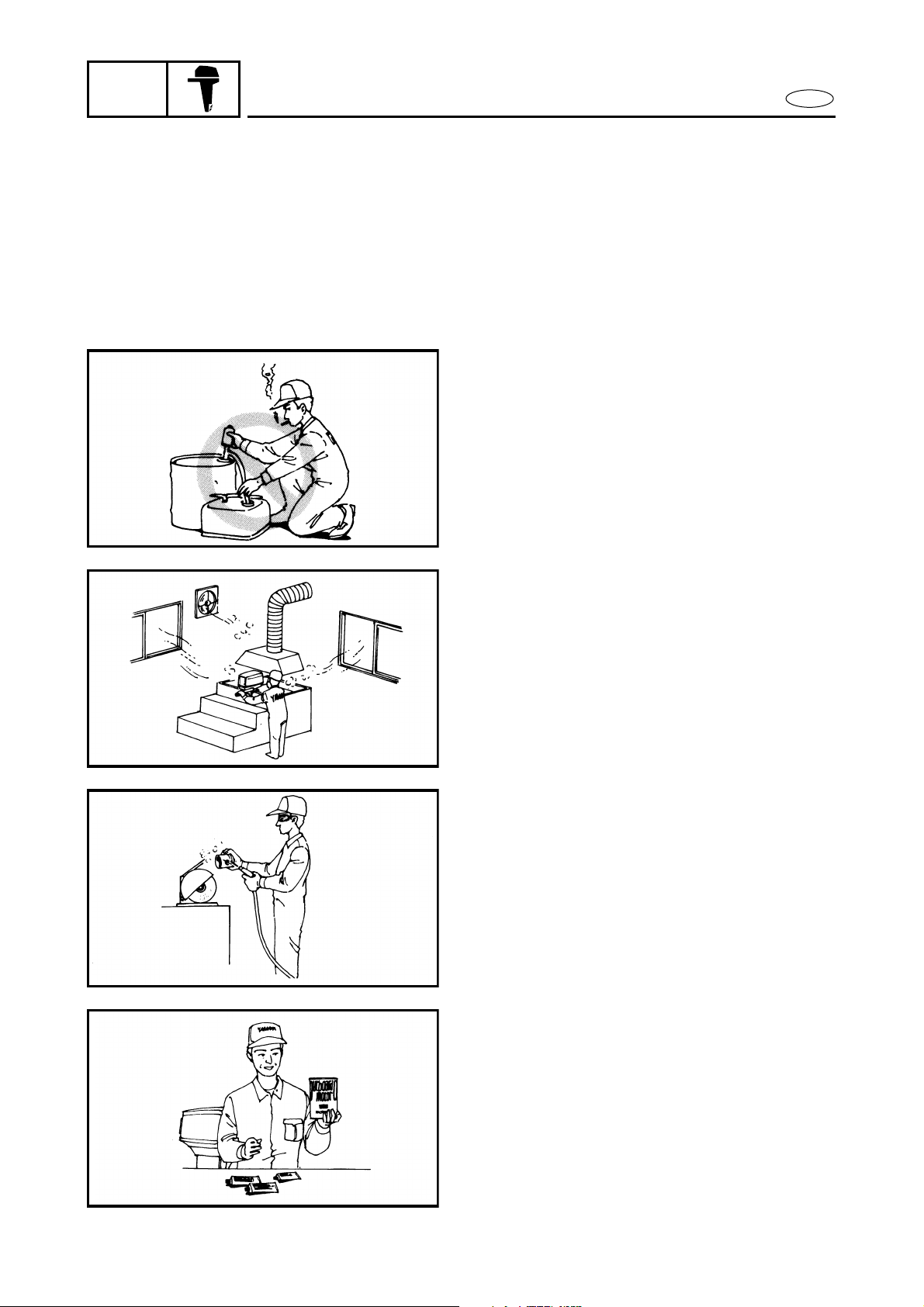
FIRE PREVENTION
Gasoline (petrol) is highly flammable.
Petroleum vapor is explosive if ignited.
Do not smoke while handling gasoline and
keep it away from heat, sparks and open
flames.
VENTILATION
Petroleum vapor is heavier than air and is
deadly if inhaled in large quantities. Engine
exhaust gases are harmful to breathe.
When test-running an engine indoors,
maintain good ventilation.
SELF-PROTECTION
Protect your eyes with suitable safety
glasses or safety goggles, when grinding or
when doing any operation which may
cause particles to fly off. Protect hands and
feet by wearing safety gloves or protective
shoes if appropriate to the work you are
doing.
OILS, GREASES AND SEALING
FLUIDS
Use only genuine Yamaha oils, greases and
sealing fluids or those recommended by
Yamaha.
1-2

GEN
INFO
F D
MESURES DE SECURITE
SICHERHEITSMASSNAHMEN
SEGURIDAD EN EL TRABAJO
ES
MESURES DE SECURITE
Les opérations décrites dans ce manuel
sont recommandées par Yamaha et doivent être suivies par les concessionnaires
Yamaha et leurs mécaniciens.
MESURES DE SECURITE
CONTRE LES INCENDIES
L’essence est un produit très inflammable.
Les vapeurs d’essence sont explosives
lorsqu’elles sont enflammées. Ne pas
fumer lors de la manipulation d’essence.
La maintenir à l’écart de la chaleur, des
étincelles et des flammes.
AERATION
Les vapeurs d’essence sont plus lourdes
que l’air; inhalées en grande quantité,
elles sont mortelles. Les gaz d’échappe-
ment du moteur sont toxiques.
Lors d’essais de fonctionnement d’un
moteur en intérieur, s’assurer que
l’endroit est bien aéré.
PROTECTION
Se protéger les yeux avec des lunettes ou
un masque de sécurité appropriés lors de
l’utilisation d’air comprimé, de ponçages
ou lors de toute opération durant laquelle
des particules risquent d’être projetées.
Si nécessaire, se protéger également les
mains et les pieds à l’aide de gants et de
chaussures de protection.
HUILES, GRAISSES ET LIQUIDES
D’ETANCHEITE
N’utiliser que les huiles, graisses et
liquides d’étanchéité Yamaha ou recommandés par Yamaha.
SICHERHEITSMASSNAHMEN
Die in diesem Handbuch angegebenen Arbeitsverfahren sind von
den Yamaha-Händlern und ihren
Mechanikern zu beachten.
BRANDSCHUTZ
Kraftstoff (Benzin) ist leicht brennbar. Benzindämpfe sind hochexplosiv. Beim Umgang mit
Kraftstoff nicht rauchen sowie
Hitze, Funken und offenes Feuer
vermeiden.
BELÜFTUNG
Benzindämpfe sind schwerer als
Luft. Bei Einatmung großer Mengen besteht Lebensgefahr. Motorabgase sind gesundheitsschädlich
und bei längerem Einatmen
lebensgefährlich. Beim Probelauf
eines Motors in geschlossenen
Räumen für ausreichende Belüftung sorgen.
SELBSTSCHUTZ
Schützen Sie bei Schleifarbeiten
oder wenn die Gefahr besteht, daß
Teilchen umherfliegen, Ihre Augen
durch eine geeignete Sicherheitsoder Schutzbrille. Tragen Sie,
wenn die Arbeit es erfordert,
Schutzhandschuhe und Sicherheitsschuhe, um Ihre Hände und
Füße zu schützen.
ÖLE, SCHMIERSTOFFE UND
DICHTUNGSMITTEL
Nur von Yamaha empfohlene Öle,
Schmierstoffe und Dichtungsmittel verwenden.
SEGURIDAD EN EL
TRABAJO
Los procedimientos incluidos en este
manual son los que Yamaha recomienda
a sus concesionarios y mecánicos.
PREVENCION DE INCENDIOS
La gasolina (petróleo) es altamente inflamable. El vapor de petróleo es explosivo
si se enciende. No fume mientras manipula gasolina y manténgala alejada del
calor, chipas y llamas.
VENTILACION
El vapor de petróleo es más pesado que
el aire y si se inhala en grandes cantidades puede provocar asfixia. Los gases de
escape del motor son dañinos. Cuando
compruebe el funcionamiento de un
motor en un local cerrado, mantenga el
lugar bien ventilado.
AUTOPROTECCION
Proteja sus ojos con gafas de seguridad
cuando utilice aire comprimido, cuando
esmerile o cuando realice cualquier operación que provoque el desprendimiento
de partículas. Proteja sus manos y pies
con guantes de seguridad o zapatos fuertes apropiados para el trabajo a realizar.
ACEITES, GRASAS Y LIQUIDOS
OBTURANTES
Utilice siempre aceites, grasas y líquidos
obturantes genuinos Yamaha, u otros
recomendados por Yamaha.
1-
2 1-3
GEN
INFO
1.
SAFETY WHILE WORKING
E
Under normal conditions of use, there
should be no hazards from the use of the
lubricants mentioned in this manual, but
safety is all-important, and by adopting
good safety practices, any risk is minimized.
A summary of the most important precautions is as follows:
1. While working, maintain good standards of personal and industrial
hygiene.
2. Clothing which has become contaminated with lubricants should be
changed as soon as practicable, and
laundered before further use.
3. Avoid skin contact with lubricants; do
not, for example, place a soiled wipingrag in your pocket.
4. Hands and any other part of the body
which have been in contact with lubricants or lubricant-contaminated clothing, should be thoroughly washed with
hot water and soap as soon as practicable.
5. To protect the skin, the application of a
suitable barrier cream to the hands
before working, is recommended.
6. A supply of clean lint-free cloths should
be available for wiping purposes.
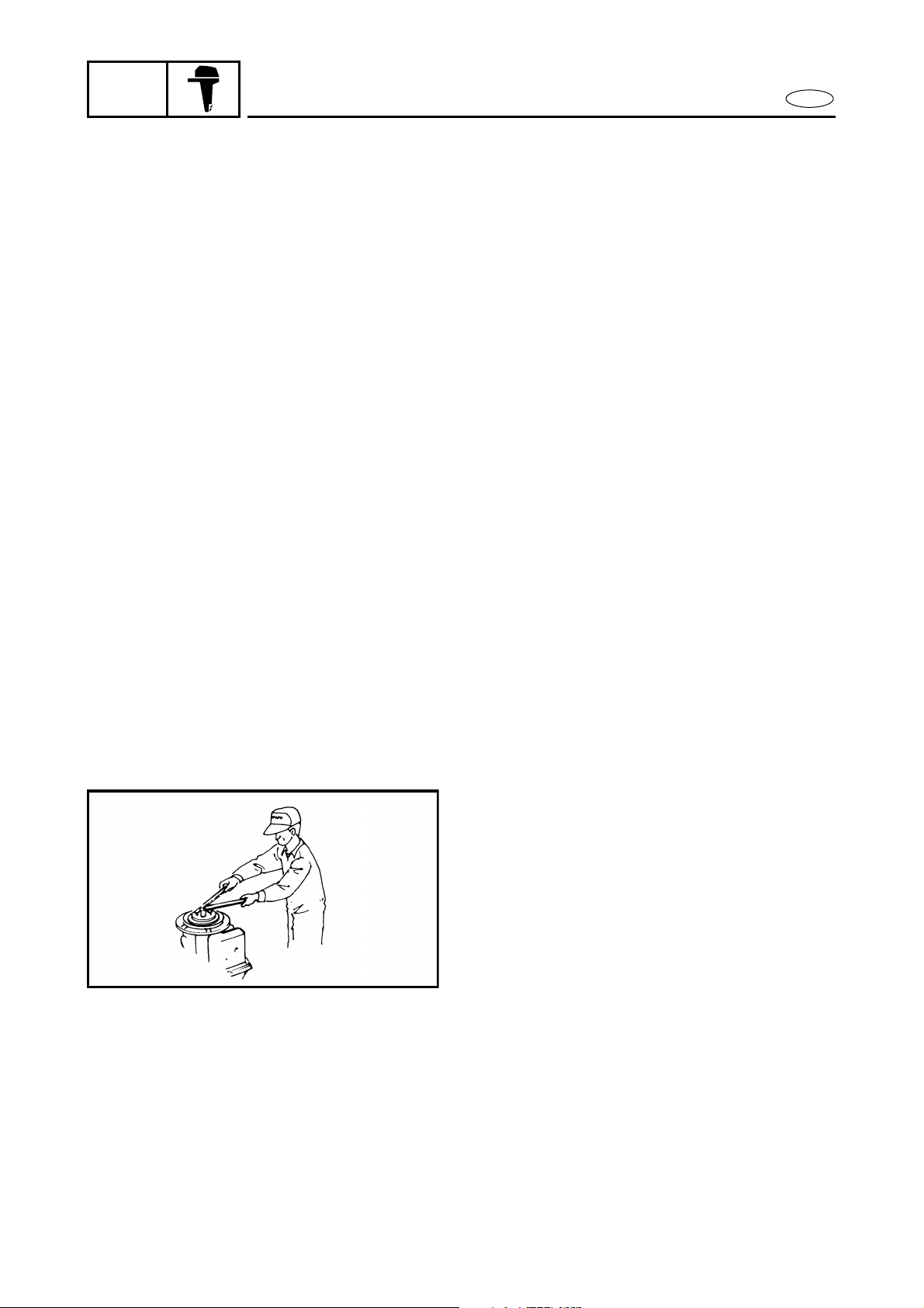
GOOD WORKING PRACTICES
The right tools
Use the recommended special tools to
protect parts from damage. Use the
right tool in the right manner – do not
improvise.
2.
Tightening torque
Follow the tightening torque instructions. When tightening bolts, nuts and
screws, tighten the large sizes first, and
tighten inner-positioned fixings before
outer-positioned ones.

MESURES DE SECURITE
GEN
INFO
En conditions normales d’utilisation, il
ne devrait pas y avoir de dangers liés à
l’utilisation des lubrifiants indiqués
dans ce manuel. Néanmoins, il convient
de prendre toutes les précautions de
sécurité nécessaires afin de minimiser
les risques.
Observer les précautions suivantes:
1. En travaillant, observer les conditions d’hygiène qui s’imposent.
2. Si les vêtements ont été souillés par
les lubrifiants, les changer dès que
possible et les laver avant de les
réutiliser.
3. Eviter le contact des lubrifiants
avec la peau et ne pas mettre en
poche un chiffon imbibé de l’un de
ces produits.
4. Si les mains ou d’autres parties du
corps ont été en contact avec des
lubrifiants ou des vêtements
souillés par ces produits, bien les
laver à l’eau chaude et au savon
dès que possible.
5. Il est recommandé de se protéger
les mains avec une crème appropriée avant de travailler.
6. Toujours prévoir une réserve de
chiffons propres et non pelucheux.
NOTES CONCERNANT
L’OUTILLAGE ET LES PIECES
1.
Outillage correct
Utiliser les outils spéciaux conseillés afin d’éviter d’endommager
les pièces. Toujours utiliser l’outil
convenant au travail à effectuer. Ne
pas improviser.
2.
Couple de serrage
Respecter les couples de serrage
spécifiés. Lors du serrage des boulons, des écrous ou des vis, serrer
tout d’abord les fixations ayant le
plus gros diamètre en allant du centre vers l’extérieur de la pièce.
SICHERHEITSMASSNAHMEN
SEGURIDAD EN EL TRABAJO
F D
1-
Unter normalen Betriebsbedingungen entstehen durch die Verwendung der in diesem Handbuch
genannten Schmierstoffe keine
Gefahren. Sicherheit ist jedoch
oberstes Gebot. Durch Beachtung
der Sicherheitsmaßnahmen werden jegliche Gefahren auf ein
Minimum begrenzt.
Nachstehend folgt eine Übersicht
der wichtigsten Sicherheitsmaß-
nahmen:
1. Während der Arbeit auf gute
persönliche Hygiene achten
und für einen sauberen
Arbeitsplatz sorgen.
2. Durch Schmiermittel verschmutzte Kleidung so bald
wie möglich wechseln und
vor der weiteren Benutzung
gründlich reinigen.
3. Schmiermittel nicht mit der
Haut in Berührung bringen.
Keine schmutzigen Lappen in
die Tasche stecken.
4. Hände und andere Körperteile, die in Berührung mit
Schmiermitteln oder durch
Schmiermittel verschmutzte
Kleidung gekommen sind, so
bald wie möglich gründlich
mit warmem Wasser und
Seife reinigen.
5. Zum Schutz der Haut wird vor
Arbeitsbeginn das Auftragen
einer geeigneten Schutzcreme empfohlen.
6. Ein Vorrat an geeigneten
Putztüchern oder saugfähigem Papier sollte stets vorhanden sein.
RICHTIGE
ARBEITSGEWOHNHEITEN
1.
Die richtigen Werkzeuge
Um Motorteile vor Beschädigung zu schützen, empfohlenes Spezialwerkzeug benutzen.
Stets das richtige Werkzeug in
der richtigen Art und Weise
benutzen – nicht improvisieren.
2.
Anzugsdrehmoment
Die vorgeschriebenen
Anzugsdrehmomente einhalten. Beim Festziehen der
Schrauben und Muttern zuerst
die größeren Schrauben
anziehen. Mit den innenliegenden Schrauben beginnen
und zuletzt die außenliegenden Schrauben anziehen.
ES
En condiciones normales de uso, el
empleo de los lubricantes mencionados
en este manual no debe plantear ningún
riesgo, pero la seguridad es un tema de la
máxima importancia, por lo que la adopción de algunas medidas de seguridad
puede reducir los posibles riesgos.
A continuación se incluye un resumen de
las precauciones más importantes:
1. Cuando trabaje, mantenga una
higiene personal e industrial
correcta.
2. La ropa contaminada con lubricante debe cambiarse tan pronto
como sea posible y ser lavada antes
de volver a usarla.
3. Evite el contacto de la piel con los
lubricantes. Por ejemplo, no introduzca un trapo impregnado en el
bolsillo.
4. Las manos y cualquier otra parte
del cuerpo que haya estado en contacto con lubricantes o ropa contaminada por lubricantes deben
lavarse minuciosamente con agua
caliente y jabón tan pronto como
sea posible.
5. Para proteger la piel, se recomienda aplicar una crema protectora apropiada en las manos antes
de iniciar el trabajo.
6. Debe disponerse de paños limpios
que no dejan pelusa para fines de
limpieza.
PROCEDIMIENTOS DE TRABAJO
CORRECTOS
1.
Las herramientas correctas
Utilice las herramientas especiales
recomendadas para evitar dañar las
piezas. Utilice la herramienta
correcta de la manera apropiada —
no improvise.
2.
Par de apriete
Siga las instrucciones relacionadas
al par de apriete. Cuando apriete
pernos, tuercas y tornillos, apriete
en primer lugar los de mayor
tamaño, y apriete los situados en la
parte interior antes de apretar los
situados en la parte exterior.
3 1-4
GEN
INFO
3.
SAFETY WHILE WORKING
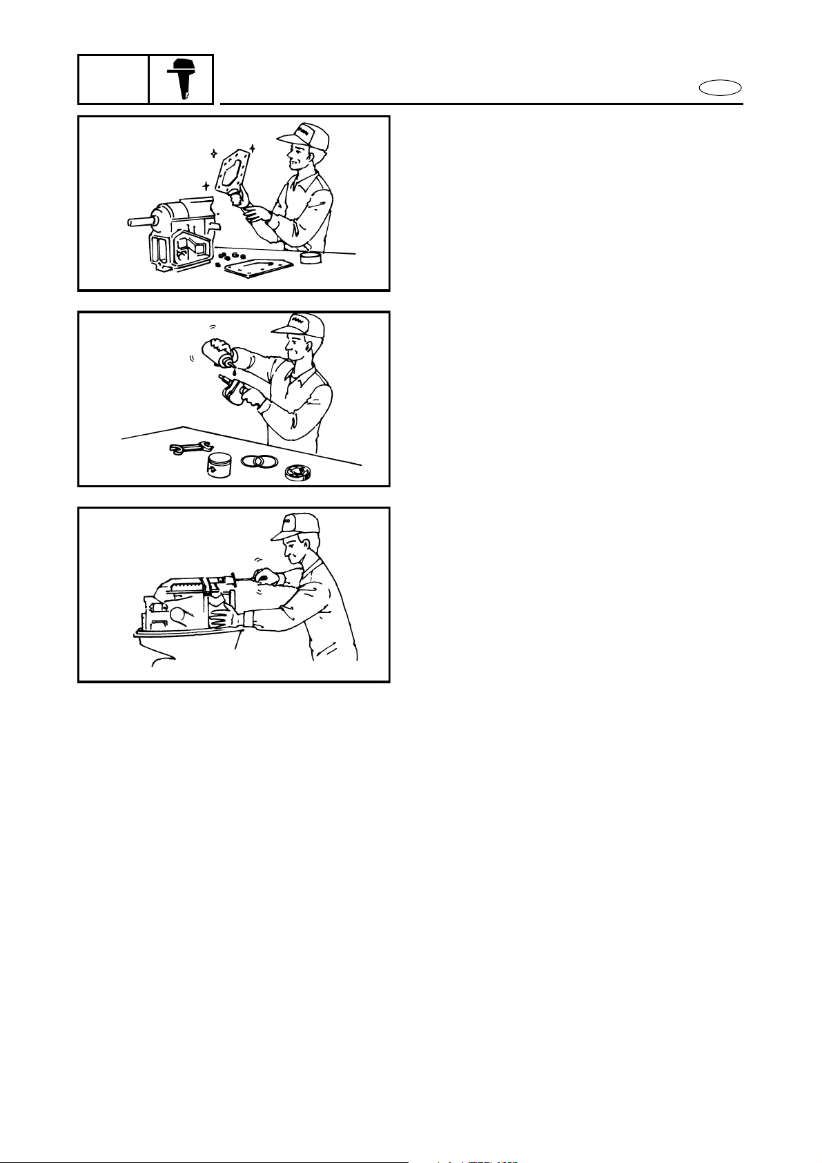
DISASSEMBLY AND ASSEMBLY
1. Clean parts with compressed air when
2. Oil the contact surfaces of moving parts
E
Non-reusable items
Always use new gaskets, packings, Orings, split-pins, circlips, etc., on reassembly.
disassembling.
before assembly.
3. After assembly, check that moving
parts operate normally.
4. Install bearings with the manufacturer’s
markings on the side exposed to view,
and liberally oil the bearings.
5. When installing oil seals, apply a light
coating of water-resistant grease to the
outside diameter.

MESURES DE SECURITE
GEN
INFO
Pièces à usage unique
Lors du remontage, toujours utiliser des joints, garnitures, joints
toriques, goupilles fendues et circlips neufs.
DEMONTAGE ET REMONTAGE
1. Lors du démontage, nettoyer les
pièces à l’air comprimé.
2. Lors du montage, huiler les surfaces de contact des pièces mobiles.
3. Après le montage, vérifier que toutes les pièces mobiles fonctionnent
normalement.
4. Monter les roulements avec la marque du fabricant tournée vers
l’extérieur et les huiler généreusement.
5. Lors du montage des bagues
d’étanchéité, appliquer une légère
couche de graisse hydrofuge sur le
diamètre extérieur.
SICHERHEITSMASSNAHMEN
SEGURIDAD EN EL TRABAJO
3.
Nicht wiederverwendbare
Teile
Beim Zusammenbau stets
neue Dichtungen, O-Ringe,
Splinte, Sicherungsringe usw.
verwenden.
ZERLEGUNG UND
ZUSAMMENBAU
1. Beim Zerlegen Teile mit
Druckluft reinigen.
2. Kontaktflächen beweglicher
Teile beim Zusammenbau fetten.
3. Nach dem Zusammenbau
bewegliche Teile auf einwandfreie Funktion prüfen.
4. Lager so einsetzen, daß die
Herstellerkennzeichen sichtbar sind. Lager ausreichend
fetten.
5. Beim Einbau der Öldichtun-
gen diese außen leicht mit
einem wasserbeständigen
Fett einreiben.
F D
1- 3.
ES
3.
Elementos no reutilizables
Utilice siempre juntas, guarniciones, juntas toroidales, pasadores
hendidos y retenedores nuevos
cuando vuelva a montar los componentes.
DESMONTAJE Y MONTAJE
1. Limpie las piezas con aire comprimido al desmontarlas.
2. Engrase las superficies de contacto
de las piezas móviles al montarlas.
3. Tras el montaje, compruebe que las
partes móviles funcionan con normalidad.
4. Instale los cojinetes con las marcas
del fabricante encaradas hacia el
lado que queda expuesto a la vista,
y engráselos abundantemente.
5. Cuando instale juntas de aceite,
aplique una capa de grasa hidró-
fuga en la circunferencia exterior.
4 1-5
GEN
INFO
SPECIAL TOOLS
E
A80000-0*
SPECIAL TOOLS
Using the correct special tools, recommended by Yamaha, will aid the work and
enable accurate assembly and tune-up.
Improvising and using improper tools can
damage the equipment.
NOTE:
For U.S.A. and Canada, use part numbers
●
that start with ”J-”, “YB-”, ”YM-”, “YU-”
or “YW-”.
For other countries, use part numbers that
●
start with “90890-”.
MEASURING
1. Tachometer
P/N. YU-08036-A............................ a
90890-06760 .......................... b
2. Mity vac
P/N. YB-35956
90890-06756
3. Pressure tester
P/N. YB-35956
90890-06762
4. Gauge block
P/N. YB-34432-16
N.A.
5. Adaptor plate
P/N. YB-34432-10
N.A.
6. Gauge base
P/N. YB-34432-11
N.A.
7. Shimming gauge
P/N. YB-06344
N.A.
8. Shimming gauge
P/N. YB-39799
9. Pinion height gauge
P/N. N.A.
90890-06702
10. Digital caliper
P/N. N.A.
90890-06704
11. Shimming plate
P/N. N.A.
90890-06701

N
OUTILLAGE SPECIAL
GEN
INFO
A80000-0*
SPEZIALWERKZEUGE
HERRAMIENTAS ESPECIALES
OUTILLAGE SPECIAL
Pour une plus grande précision dans vos
travaux de montage et de mise au point,
Yamaha vous recommande l’emploi
d’outils spéciaux. Vos travaux s’en trouveront ainsi facilités. En outre, l’utilisa-
tion d’outils non adaptés risque
d’endommager le matériel.
.B.:
Pour les Etats-Unis et le Canada, utili-
●
ser les outils dont le numéro de réfé-
rence commence par “J-”, “YB-”,
“YM-”, “YU-” ou “YW-”.
●
Pour les autres pays, commander et
utiliser les outils dont le numéro de
référence commence par “90890-”.
MESURAGE
1. Compte-tours
P/N. YU-08036-A ............... a
90890-06760 .............. b
2. Mity Vac
P/N. YB-35956
90890-06756
3. Testeur de pression
P/N. YB-35956
90890-06762
4. Bloc de jauge
P/N. YB-34432-16
N.A.
5. Plaque d’adaptation
P/N. YB-34432-10
N.A.
6. Base de jauge
P/N. YB-34432-11
N.A.
7. Jauge de mesure de cale
P/N. YB-06344
N.A.
8. Jauge de mesure de cale
P/N. YB-39799
9. Jauge de hauteur de pignon
P/N. N.A.
90890-06702
10. Pied à coulisse numérique
P/N. N.A.
90890-06704
11. Plaque de mesure de cale
P/N. N.A.
90890-06701
A80000-0*
SPEZIALWERKZEUGE
Für komplette und korrekte Einstellungen und Montagearbeiten
sind die richtigen Spezialwerkzeuge erforderlich. Durch Einsatz
von Spezialwerkzeugen werden
Schäden verhindert, die entstehen können, wenn falsche Werkzeuge oder Verfahren verwendet
werden.
HINWEIS:
Für die USA und Kanada bezie-
●
hen Sie sich auf die mit “J-”,
“YB-”, “YM-”, “YU-” oder “YW-”
beginnenden Teilenummen.
●
Für andere Länder beziehen Sie
sich auf die mit “90890-” beginnenden Teilenummen.
MESSEN
1. Drehzahlmesser
P/N. YU-08036-A.............. a
90890-06760............. b
2. Mity Vac
P/N. YB-35956
90890-06756
3. Druckmeßgerät
P/N. YB-35956
90890-06762
4. Einstellscheibenlehren-Block
P/N. YB-34432-16
N.A.
5. Adapterplatte
P/N. YB-34432-10
N.A.
6. Einstellscheibenlehren-Basis
P/N. YB-34432-11
N.A.
7. Einstellscheibenlehre
P/N. YB-06344
N.A.
8. Einstellscheibenmeßwerkzeug
P/N. YB-39799
9. Ritzelhöhenlehre
P/N. N.A.
90890-06702
10. Digital-Schublehre
P/N. N.A.
90890-06704
11. Einstellscheibenplatte
P/N. N.A.
90890-06701
F D
ES
A80000-0*
HERRAMIENTAS
ESPECIALES
El uso de las herramientas especiales
correctas recomendadas por Yamaha le
ayudará en el trabajo y asegurará un
montaje y puesta a punto con precisión.
La improvisación y el empleo de herramientas incorrectas puede provocar
daños en el equipo.
NOTA:
Para EE.UU. y Canadá, utilice los
●
números de pieza que empiecen por
“J-”, “YB-”, “YM-”, “YU-” o “YW-”.
Para otros países, utilice los números
●
de pieza que empiecen por “90890-”.
MEDICION
1. Tacómetro
P/N.˚ YU-08036-A ............... a
90890-06760 ............... b
2. Mity Vac
P/N.˚ YB-35956
90890-06756
3. Probador de presión
P/N.˚ YB-35956
90890-06762
4. Bloque de medidores
P/N.˚ YB-34432-16
N.A.
5. Placa del adaptador
P/N.˚ YB-34432-10
N.A.
6. Base del medidor
P/N.˚ YB-34432-11
N.A.
7. Medidor de laminillas
P/N.˚ YB-06344
N.A.
8. Medidor de laminillas
P/N.˚ YB-39799
9. Medidor de la altura del piñón
P/N.˚ N.A.
90890-06702
10. Calibrador digital
P/N.˚ N.A.
90890-06704
11. Placa de laminillas
P/N.˚ N.A.
90890-06701
5
1-
GEN
INFO
SPECIAL TOOLS
E
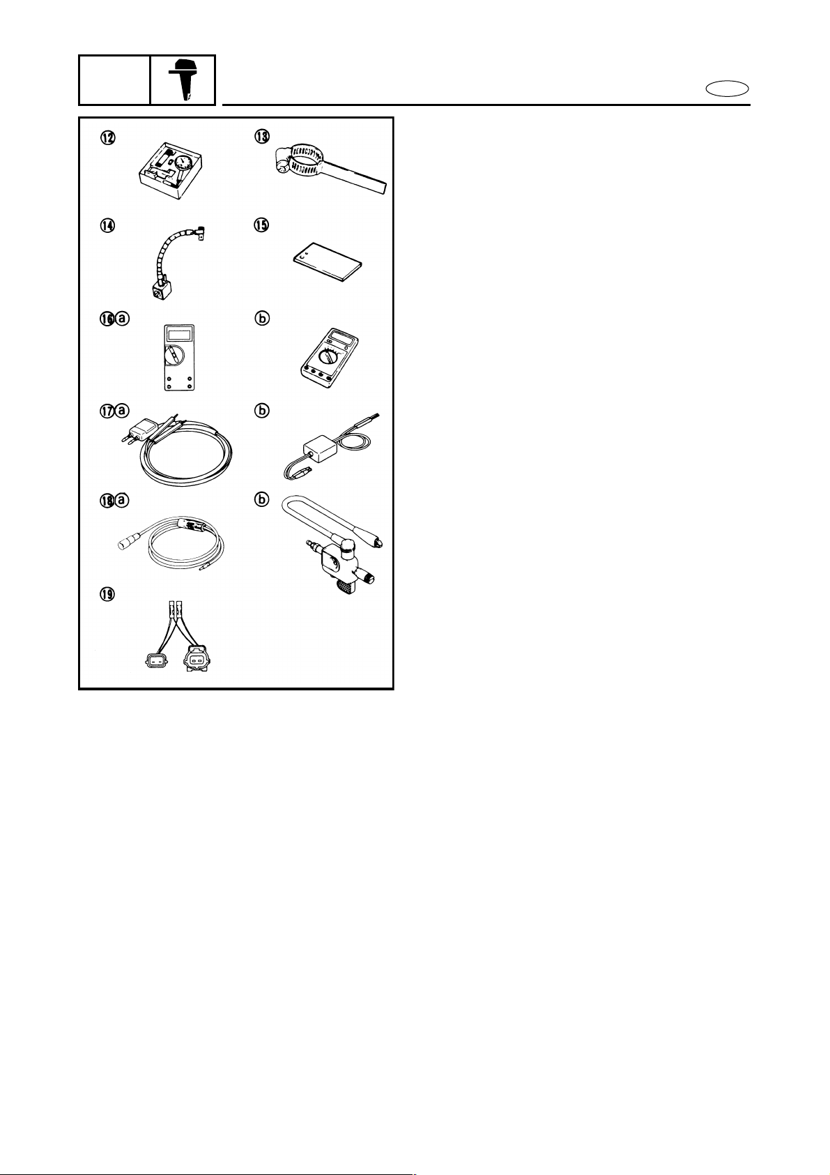
12. Dial gauge
P/N. YU-03097
90890-01252
13. Backlash indicator
P/N. YB-06265
90890-06706
14. Flexible stand
P/N. YU-34481
90890-06705
15. Base plate
P/N. YB-07003
N.A.
16. Digital circuit tester
P/N. J-39299 .................................. a
90890-06752 .......................... b
17. Peak voltage adaptor
P/N. YU-39991 ............................... a
90890-03169 .......................... b
18. Spark gap tester
P/N. YM-34487............................... a
90890-06754 .......................... b
19. Test harness
P/N. YB-06768
90890-06768
1-6

OUTILLAGE SPECIAL
GEN
INFO
12. Comparateur à cadran
P/N. YU-03097
90890-01252
13. Indicateur de jeu de retour
P/N. YB-06265
90890-06706
14. Support flexible
P/N. YU-34481
90890-06705
15. Plaque de base
P/N. YB-07003
N.A.
16. Testeur numérique
P/N. J-39299........................ a
90890-06752 .............. b
17. Adaptateur de tension de crête
P/N. YU-39991 ................... a
90890-03169 ............... b
18. Testeur de longueur d’étincelle
P/N. YM-34487................... a
90890-06754 ............... b
19. Faisceau de test
P/N. YB-06768
90890-06768
SPEZIALWERKZEUGE
HERRAMIENTAS ESPECIALES
12. Meßuhr
P/N. YU-03097
90890-01252
13. Spiel-Anzeigeuhr
P/N. YB-06265
90890-06706
14. Schwanenhals
P/N. YU-34481
90890-06705
15. Basisplatte
P/N. YB-07003
N.A.
16. Digitalprüfgerät
P/N. J-39299..................... a
90890-06752............. b
17. Spitzenspannungsadapter
P/N. YU-39991 ................. a
90890-03169............. b
18. Zündfunkenprüfer
P/N. YM-34487................. a
90890-06754............. b
19. Diagnosegerät
P/N. YB-06768
90890-06768
F
D
ES
12. Medidor de cuadrantes
P/N.˚ YU-03097
90890-01252
13. Indicador del contragolpe
P/N.˚ YB-06265
90890-06706
14. Soporte flexible
P/N.˚ YU-34481
90890-06705
15. Placa de base
P/N.˚ YB-07003
N.A.
16. Probador de circuitos digital
P/N.˚ J-39299........................ a
90890-06752 ............... b
17. Adaptador de tensión pico
P/N.˚ YU-39991.................... a
90890-03169 ............... b
18. Probador de huelgos de bujía
P/N.˚ YM-34487 ................... a
90890-06754 ............... b
19. Mazo de cables de prueba
P/N.˚ YB-06768
90890-06768
1-
6
GEN
INFO
SPECIAL TOOLS
REMOVAL AND INSTALLATION
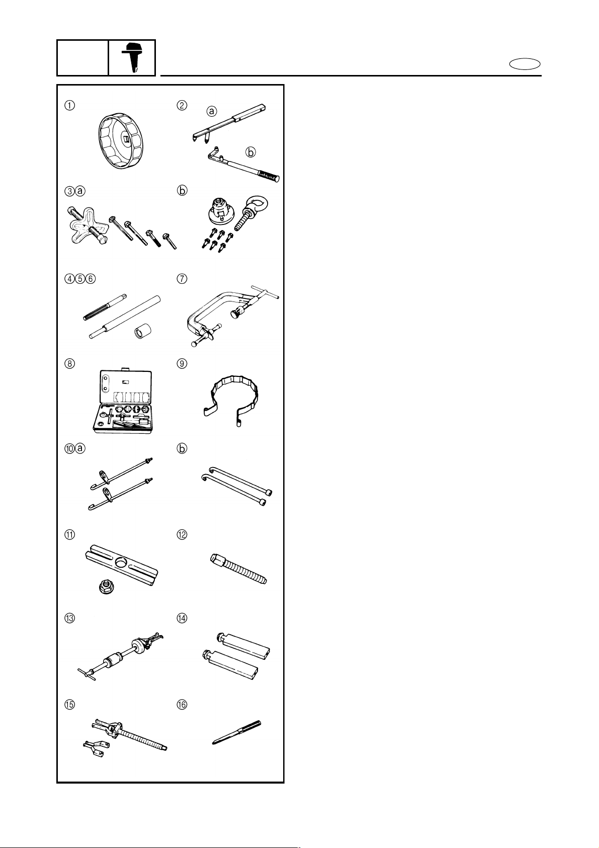
1. Oil filter wrench
P/N. YU-38411
90890-01426
2. Flywheel holder
P/N. YB-06139................................ a
90890-06522 .......................... b
3. Universal puller
P/N. YB-06117................................ a
90890-06521 .......................... b
4. Valve guide remover/installer
P/N. 90890-06801
5. Valve guide installer attachment
P/N. YM-04015
90890-06802
6. Valve guide reamer
P/N. 90890-06804
7. Valve spring compressor
P/N. YM-01253
90890-04019
8. Valve seat cutter set
P/N. YM-91043-C
90890-06803
9. Piston slider
P/N. YU-33294
90890-06529
10. Bearing housing puller
P/N. YB-06234................................ a
90890-06503 .......................... b
11. Stopper guide plate
P/N. N.A.
90890-06501
12. Center bolt
P/N. N.A.
90890-06504
13. Slide hammer set
P/N. YB-06096
90890-06531
14. Stopper guide stand
P/N. N.A.
90890-06538
15. Bearing puller
P/N. N.A.
90890-06535
16. Driver rod (M10)
P/N. YB-06229
E
1-7

OUTILLAGE SPECIAL
GEN
INFO
DEPOSE ET INSTALLATION
1. Clé de filtre à huile
P/N. YU-38411
90890-01426
2. Outil de maintien de volant magné-
tique
P/N. YB-06139.................... a
90890-06522 .............. b
3. Extracteur universel
P/N. YB-06117.................... a
90890-06521 .............. b
4. Outil de dépose/installation de
guide de soupape
P/N. 90890-06801
5. Outil de montage de guide de soupape
P/N. YM-04015
90890-06802
6. Alésoir de guide de soupape
P/N. 90890-06804
7. Compresseur de ressort de soupape
P/N. YM-01253
90890-04019
8. Jeu de fraises pour siège de soupape
P/N. YM-91043-C
90890-06803
9. Coulisseau de piston
P/N. YU-33294
90890-06529
10. Extracteur de logement de
roulement
P/N. YB-06234.................... a
90890-06503 .............. b
11. Plaquette de guide de butée
P/N. N.A.
90890-06501
12. Boulon de centrage
P/N. N.A.
90890-06504
13. Jeu de marteaux à coulisseau
P/N. YB-06096
90890-06531
14. Support de guide de butée
P/N. N.A.
90890-06538
15. Extracteur de roulement
P/N. N.A.
90890-06535
16. Tige d’entraînement (M10)
P/N. YB-06229
SPEZIALWERKZEUGE
HERRAMIENTAS ESPECIALES
AUSBAU UND EINBAU
1. Ölfilterschlüssel
P/N. YU-38411
90890-01426
2. Schwungradhalter
P/N. YB-06139.................. a
90890-06522............. b
3. Universal-Lagerabzieher
P/N. YB-06117.................. a
90890-06521............. b
4. Ventilführungs/EinsetzerAbzieher
P/N. 90890-06801
5. Ventilführungs-Eintreibervorsatz
P/N. YM-04015
90890-06802
6. Ventilführungs-Reibahle
P/N. 90890-06804
7. Ventilfederdrücker
P/N. YM-01253
90890-04019
8. Ventilsitzschneider-Satz
P/N. YM-91043-C
90890-06803
9. Kolbeneinsetzer
P/N. YU-33294
90890-06529
10. Lagergehäuse-Abzieher
P/N. YB-06234.................. a
90890-06503............. b
11. Anschlagführungsplatte
P/N. N.A.
90890-06501
12. Zentrierbolzen
P/N. N.A.
90890-06504
13. Schiebehammersatz
P/N. YB-06096
90890-06531
14. Anschlagführungsständer
P/N. N.A.
90890-06538
15. Lagerabzieher
P/N. N.A.
90890-06535
16. Eintreiberstange (M10)
P/N. YB-06229
F
D
ES
EXTRACCION E INSTALACION
1. Llave para filtros de aceite
P/N.˚ YU-38411
90890-01426
2. Soporte del volante de motor
P/N.˚ YB-06139.................... a
90890-06522 ............... b
3. Extractor universal
P/N.˚ YB-06117.................... a
90890-06521 ............... b
4. Extractor/instalador de guías de
válvulas
P/N.˚ 90890-06801
5. Accesorio del instalador de guías
de válvula
P/N.˚ YM-04015
90890-06802
6. Escariador de guías de válvula
P/N.˚ 90890-06804
7. Compresor de resortes de válvula
P/N.˚ YM-01253
90890-04019
8. Juego de cortadores de asientos de
válvula
P/N.˚ YM-91043-C
90890-06803
9. Corredera de pistón
P/N.˚ YU-33294
90890-06529
10. Extractor de caja de cojinetes
P/N.˚ YB-06234.................... a
90890-06503 ............... b
11. Placa guía del tope
P/N.˚ N.A.
90890-06501
12. Perno central
P/N.˚ N.A.
90890-06504
13. Juego de martillo deslizante
P/N.˚ YB-06096
90890-06531
14. Soporte de guía de tope
P/N.˚ N.A.
90890-06538
15. Extractor de cojinetes
P/N.˚ N.A.
90890-06535
16. Varilla impulsora (M10)
P/N.˚ YB-06229
1-
7
GEN
INFO
SPECIAL TOOLS
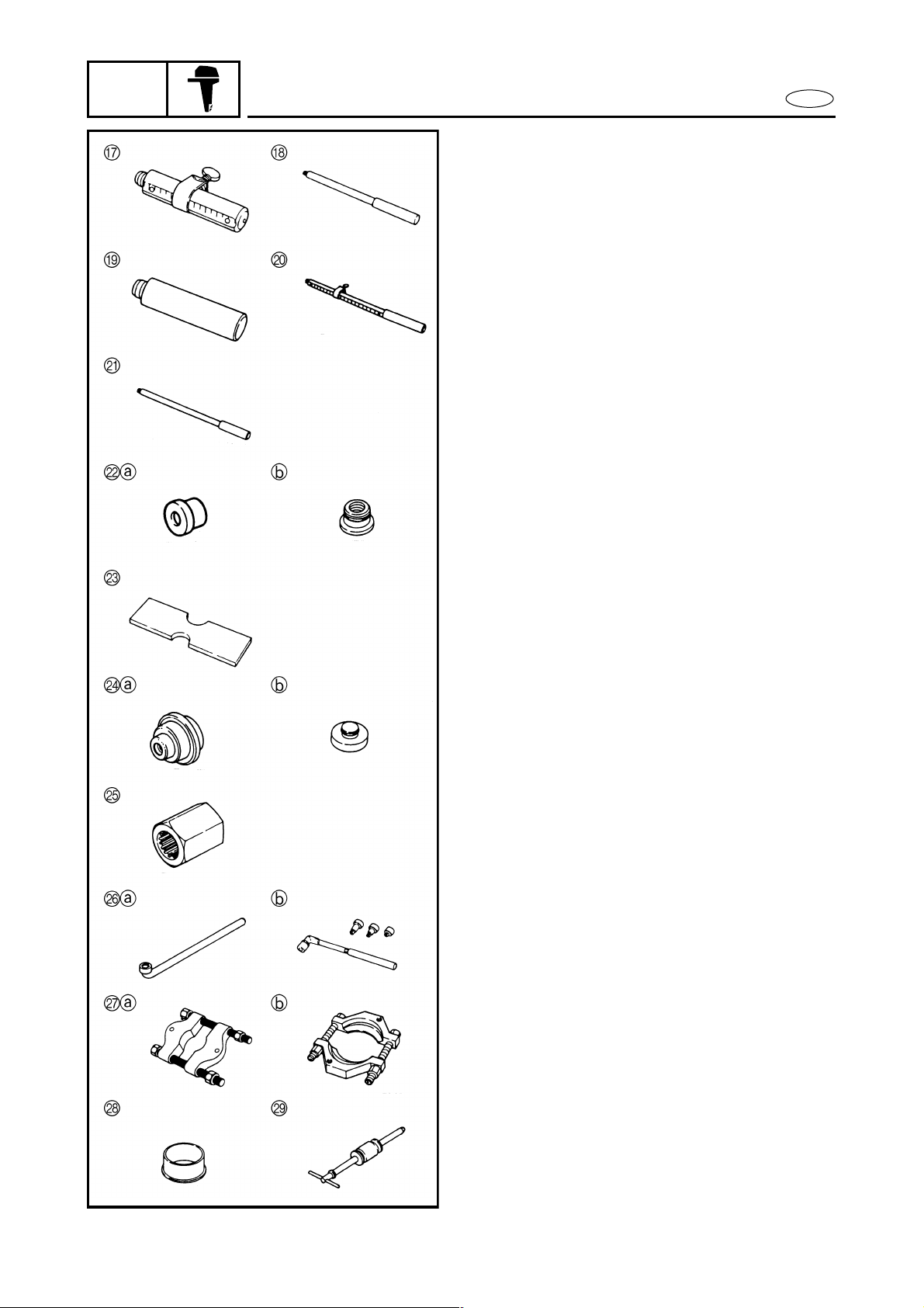
17. Driver rod (M10)
P/N. 90890-06604
18. Driver rod (M12)
P/N. YB-06071
19. Driver rod (M12)
P/N. 90890-06606
20. Driver rod (M10)
P/N. 90890-06602
21. Driver rod (5/8-18UNF)
P/N. 90890-06605
22. Needle bearing attachment
P/N. YB-06082................................ a
90890-06615 .......................... b
23. Bearing depth plate
P/N. N.A.
90890-06603
24. Ball bearing attachment
(oil seal installer)
P/N. YB-06168................................ a
90890-06637 .......................... b
25. Drive shaft holder
P/N. YB-06079-A
90890-06517
26. Pinion nut holder
P/N. YB-06078................................ a
90890-06505 .......................... b
27. Bearing separator
P/N. YB-06219................................ a
90890-06534 .......................... b
28. Bearing inner race installer
P/N. N.A.
90890-06643
29. Slide hammer handle
P/N. YB-06096
90890-06531
E
1-8
 Loading...