

Yamaha F200B, FL200B, F250G, FL250G Service Manual

F200B
FL200B
F250G
FL250G
SERVICE MANUAL
6DX-28197-5P-11
Preface
This manual has been prepared by Yamaha primarily for use by Yamaha dealers and their trained
mechanics when performing maintenance procedures and repairs to Yamaha equipment. It has
been written to suit the needs of persons who have the Bronze Technical Certificate of the YTA
(Yamaha Technical Academy) marine or the equivalent basic understanding of the mechanical and
electrical concepts and procedures inherent in the work, for without such knowledge attempted
repairs or service to the equipment could render it unsafe or unfit for use.
Because Yamaha has a policy of continuously improving its products, models may differ in detail
from the descriptions and illustrations given in this publication. Use only the latest edition of this
manual. Authorized Yamaha dealers are notified periodically of modifications and significant
changes in specifications and procedures, and these are incorporated in successive editions of this
manual. Also, up-to-date parts information is available on YPEC-web. Additional information and
up-to-date information on Yamaha products and services are available on Yamaha Service Portal.
Important information
Particularly important information is distinguished in this manual by the following notations:
The Safety Alert Symbol means ATTENTION! BECOME ALERT! YOUR SAFETY IS
INVOLVED!
A WARNING indicates a hazardous situation which, if not avoided, could result in death or
serious injury.
A NOTICE indicates special precautions that must be taken to avoid damages to the outboard motor or other property.
TIP:
A TIP provides key information to make procedures easier or clearer.
F200B, FL200B, F250G, FL250G
SERVICE MANUAL
©2011 by Yamaha Motor Co., Ltd.
1st Edition, July 2011
All rights reserved.
Any reprinting or unauthorized use
without the written permission of
Yamaha Motor Co., Ltd.
is expressly prohibited.
Contents
General information
Specification
Technical features and description
Rigging information
Troubleshooting
Electrical system
GEN
INFO
SPEC
TECH
FEA
RIG
GING
TRBL
SHTG
ELEC
0
1
2
3
4
5
Fuel system
Power unit
Lower unit
Bracket unit
Maintenance
Index
FUEL
POWR
LOWR
BRKT
MNT
6
7
8
9
10
Appendix
A


GEN
INFO
General information
Safety while working ..................................................... 0-1
Rotating part............................................................................... 0-1
Hot part....................................................................................... 0-1
Electric shock ............................................................................. 0-1
Propeller ..................................................................................... 0-1
Handling of gasoline................................................................... 0-1
Ventilation................................................................................... 0-1
Self-protection ............................................................................ 0-2
Working with crane..................................................................... 0-2
Handling of gas torch ................................................................. 0-2
Part, lubricant, and sealant......................................................... 0-2
Handling of sealant..................................................................... 0-2
Special service tool .................................................................... 0-3
Tightening torque ....................................................................... 0-3
Non-reusable part....................................................................... 0-3
Disassembly and assembly........................................................ 0-3
0
How to use this manual ..................................................... 0-4
Manual format ............................................................................ 0-4
Abbreviation ............................................................................... 0-5
Lubricant, sealant, and thread locking agent.................. 0-7
Symbol ....................................................................................... 0-7
Special service tool............................................................ 0-9
GEN
INFO
General information
Safety while working
To prevent an accident or injury and to provide quality service, observe the following
safety procedures.
Rotating part
• Hands, feet, hair, jewelry, clothing, personal flotation device straps, and so on,
can become entangled with internal rotating
parts of the engine, resulting in serious
injury or death.
• Keep the top cowling installed whenever
possible. Do not remove or install the top
cowling when the engine is running.
• Only operate the engine with the top cowling removed according to the specific
instructions in the manual. Keep hands,
feet, hair, jewelry, clothing, personal flotation device straps, and so on, away from
any exposed moving parts.
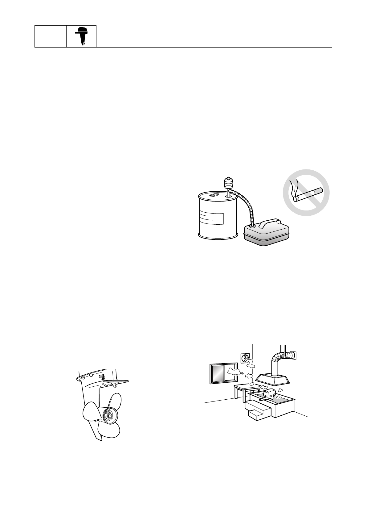
Handling of gasoline
• Gasoline is highly flammable. Keep gasoline and all flammable products away from
heat, sparks, and open flames.
• Gasoline is poisonous and can cause injury
or death. Handle gasoline with care. Never
siphon gasoline by mouth. If you swallow
some gasoline, inhale a lot of gasoline
vapor, or get some gasoline in your eyes,
see your doctor immediately. If gasoline
spills on your skin, wash with soap and
water. If gasoline spills on your clothing,
change your clothes.
Hot part
During and after operation, engine parts are
hot enough to cause burns. Do not touch any
parts under the top cowling until the engine
has cooled.
Electric shock
Do not touch any electrical parts while starting or operating the engine. Otherwise, shock
or electrocution could result.
Propeller
Do not hold the propeller with your hands
when loosening or tightening the propeller
nut.
Ventilation
• Gasoline vapor and exhaust gas are
heavier than air and extremely poisonous.
If gasoline vapor or exhaust gas is inhaled
in large quantities, it may cause loss of consciousness and death within a short time.
• When test running an engine indoors (for
example, in a water tank) make sure to do
so where adequate ventilation can be maintained.
0-1
Safety while working
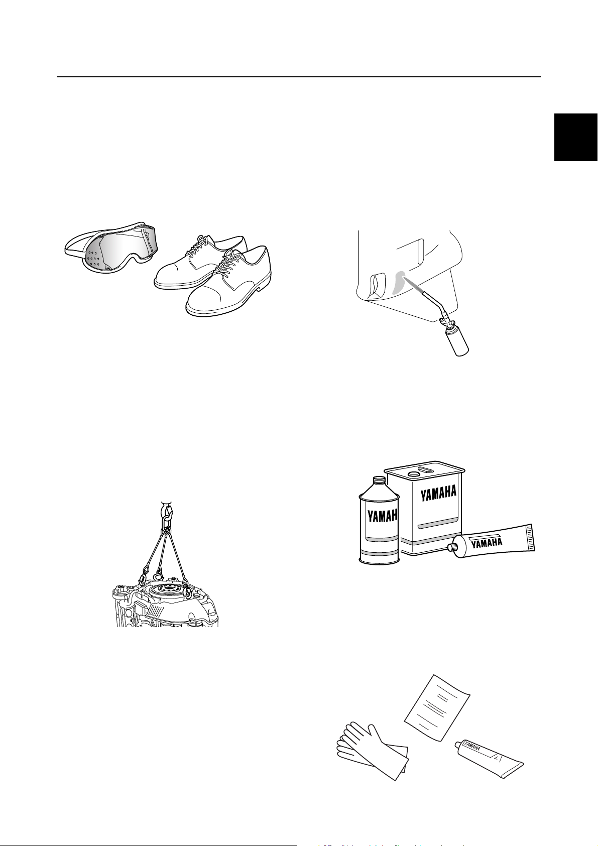
Self-protection
• Protect your eyes by wearing safety
glasses or safety goggles during all operations involving drilling and grinding, or when
using an air compressor.
• Protect your hands and feet by wearing
protective gloves and safety shoes when
necessary.
Working with crane
• Outboard motors weighing 18.0 kg (39.7 lb)
and over must be carried by a crane.
• Use the wire ropes of adequate strength,
and lift up the outboard motor using the
three point suspension.
• If the outboard motor does not have three
or more points to be suspended, support it
using additional ropes or the like so that the
outboard motor can be lifted and carried in
a stable manner.
Handling of gas torch
• Improper handling of a gas torch may result
in burns. For information on the proper handling of the gas torch, see the operation
manual issued by the manufacturer.
• When using a gas torch, keep it away from
the gasoline and oil, to prevent a fire.
• Components become hot enough to cause
burns. Do not touch any hot components
directly.
Part, lubricant, and sealant
Use only genuine Yamaha parts, lubricants,
and sealants, or those recommended by
Yamaha, when servicing or repairing the outboard motor.
0
Handling of sealant
• Wear protective gloves to protect your skin,
when using the sealants.
• See the material safety data sheet issued
by the manufacturer. Some of the sealants
may be harmful to human health.
0-2
GEN
INFO
General information
Special service tool
Use the recommended special service tools
to work safely, and to protect parts from damage.
Tightening torque
Follow the tightening torque specifications
provided throughout the manual. When tightening nuts, bolts, and screws, tighten the
large sizes first, and tighten fasteners starting
in the center and moving outward.
Non-reusable part
Always use new gaskets, seals, O-rings, cotter pins, and so on, when installing or assembling parts.
Disassembly and assembly
• Use compressed air to remove dust and dirt
during disassembly.
• Apply engine oil to the contact surfaces of
moving parts before assembly.
• Install bearings so that the bearing identification mark is facing in the direction indicated in the installation procedure. In
addition, make sure to lubricate the bearings liberally.
• Apply a thin coat of water resistant grease
to the lip and periphery of an oil seal before
installation.
• Check that moving parts operate normally
after assembly.
0-3
Safety while working / How to use this manual
How to use this manual
Manual format
The format of this manual has been designed to make service procedures clear and easy to understand. Use the following information as a guide for effective and quality service.
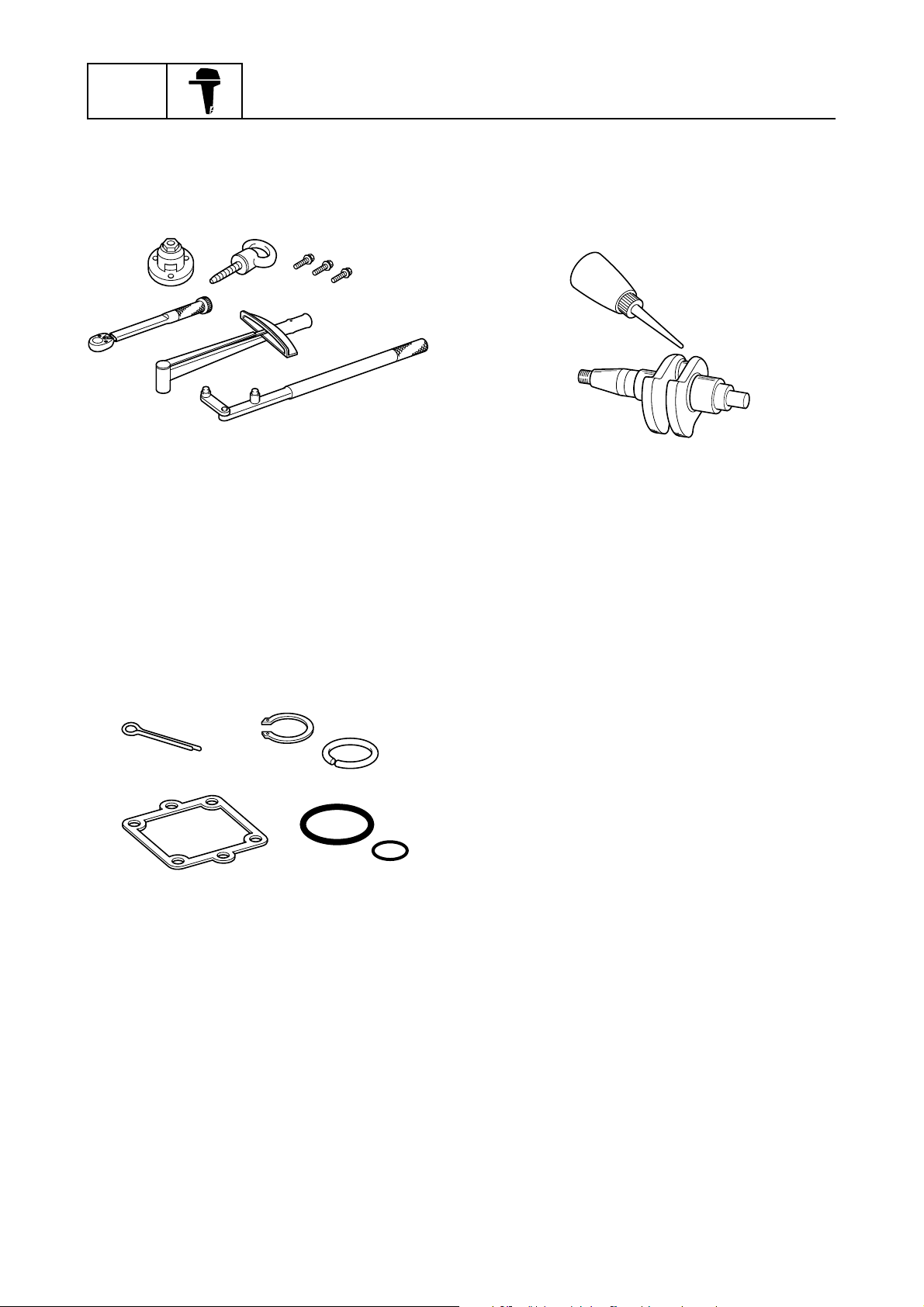
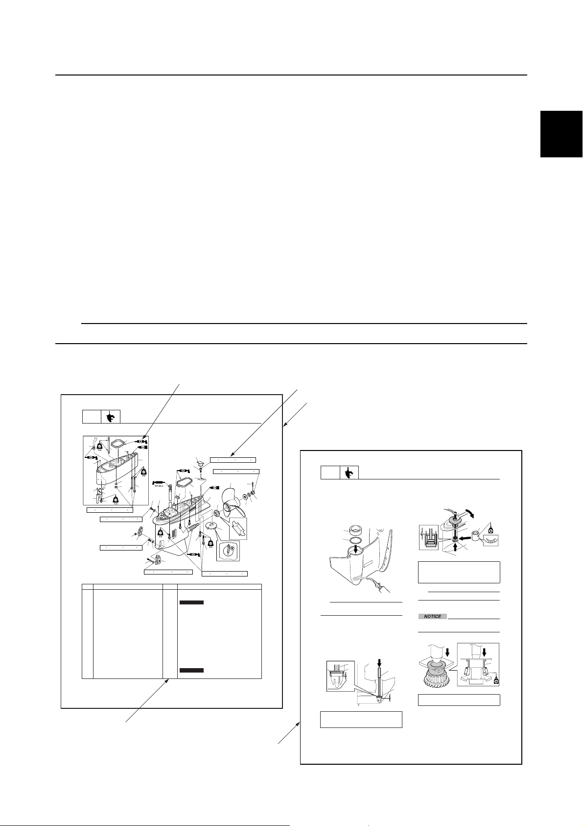
• Parts are shown and detailed in an exploded diagram and are listed in the component list (see 1
in the following figure for an example page).
• The component list consists of part names and quantities, as well as bolt and screw dimensions
(see 2 in the following figure).
• Symbols are used to indicate important aspects of a procedure, such as the grade of lubricant and
the lubrication points (see 3 in the following figure).
• Tightening torque specifications are provided in the exploded diagrams (see 4 in the following fig-
ure), and in the related detailed instructions. Some torque specifications are listed in stages as
torque figures or angles in degrees.
• Separate procedures and illustrations are used to explain the details of removal, checking, and
installation where necessary (see 5 in the following figure for an example page).
TIP:
For troubleshooting procedures, see Chapter 4, “Troubleshooting.”
0
3
LOWR
Lower unit (regular rotation model)
È
26
25
24
23
47 N
No. Part name Q’ty Remarks
1 Water inlet cover (PORT) 1
2 Bolt 1 M5 40 mm
3Gasket 2
4 Drain screw 1
5 Water inlet cover (STBD) 1
6 Self-locking nut 1
7 Check screw 1
8Dowel 2
9Plate 1
10 Rubber seal 1
11 Bolt 1 M10 45 mm
12 Grommet 1
13 Lower unit 1
14 Spacer 1
15 Propeller 1
16 Cotter pin 1
17 Propeller nut 1
È U-transom model
8-1
Lower unit
25
27
33
32
31
34
35
m (4.7 kgf m, 34.7 ft lb)
9 N
m (0.9 kgf m, 6.6 ft lb)
9 N m (0.9 kgf m, 6.6 ft lb)
28
6
29
30
5
2
2.3 N
8
7
3
22
4
3
1
m (0.23 kgf m, 1.70 ft lb)
12
11
8
9
22
22
x
Not reusable
x
Not reusable
42 N m (4.2 kgf m, 31.0 ft lb)
10
13
21
47 N
m (4.7 kgf m, 34.7 ft lb)
54 N
2
m (5.4 kgf m, 39.8 ft lb)
15
14
20
4
1
LOWR
16
17
18
19
2. Heat the installation area of the taper
roller bearing outer race in the lower case
with a gas torch, and then install the
outer race 2.
the lower case, heat the entire
installation area evenly. Otherwise,
the paint on the lower case could be
burned.
TIP:
Do not reuse a shim if it is any deformed or
scratched.
3. While holding the special service tool 3,
strike the tool to check that the taper
roller bearing outer race is installed
properly. If a high-pitched metallic sound
is produced when the special service tool
is struck, the outer race is installed
properly.
Driver rod LL 3: 90890-06605
Bearing outer race attachment 4:
90890-06658
Lower unit
NOTICE:
When heating
2
1
3
4
3
4. Install the rollers into the needle bearing
outer race, and install the special service
tool into the needle bearing assembly 5,
and then install the needle bearing
assembly 5.
Ball bearing attachment 6:
90890-06655
Bearing outer race puller assembly 7:
90890-06523
TIP:
The needle bearing contains 28 rollers.
Assembling the forward gear
Do not reuse the bearing, always replace
it with a new one.
1. Install a new taper roller bearing.
4
Bearing inner race attachment 1:
90890-06659
5
7
6
1
5
8-19
0-4

GEN
INFO
Abbreviation
The following abbreviations are used in this service manual.
Abbreviation Description
ABYC American Boat and Yacht Council
AFT Aft end
API American Petroleum Institute
APS Accelerator Position Sensor
ATF Automatic Transmission Fluid
AWG American Wire Gauge
BOW Bow end
BTDC Before Top Dead Center
C/E Check Engine
C/L Centerline
CCA Cold Cranking Ampere
DN Down side
DOHC Dual Over Head Camshaft
ECM Electronic Control Module
General information
EN European Norm (European standard)
ETV Electronic Throttle Valve
EX Exhaust
EXH Exhaust
FForward
GPS Global Positioning System
IEC International Electro-technical Commission
IN Intake
INT Intake
ISC Idle Speed Control
ISO International Organization for Standardization
LAN Local Area Network
N Neutral
OCV Oil Control Valve
PCV Pressure Control Valve
PORT Port side
PTT Power Trim and Tilt
R Reverse
RON Research Octane Number
SAE Society of Automotive Engineers
STBD Starboard side
SW Switch
TCI Transistor-Controlled Ignition
TDC Top Dead Center
0-5

Abbreviation Description
TPS Throttle Position Sensor
UP Upside
VCT Variable Camshaft Timing
W/F Water in Fuel
YDIS Yamaha Diagnostic System
How to use this manual
0
0-6
GEN
INFO
General information
Lubricant, sealant, and thread locking agent
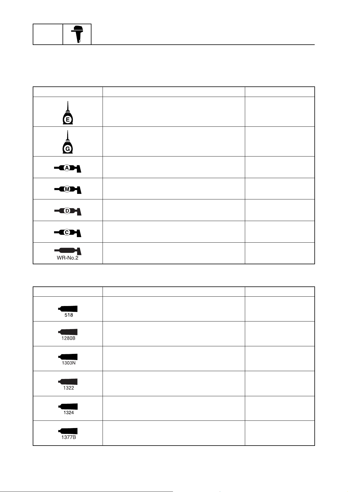
Symbol
Symbols in an exploded diagram or illustration indicate the grade of lubricant and the lubrication
points.
Symbol Name Application
Yamaha 4-stroke motor oil Lubricant
Gear oil Lubricant
Water resistant grease
(Yamaha grease A)
Molybdenum disulfide grease Lubricant
Corrosion resistant grease
(Yamaha grease D)
Low temperature resistant grease
(Yamaha grease C)
WR-No.2 grease Lubricant
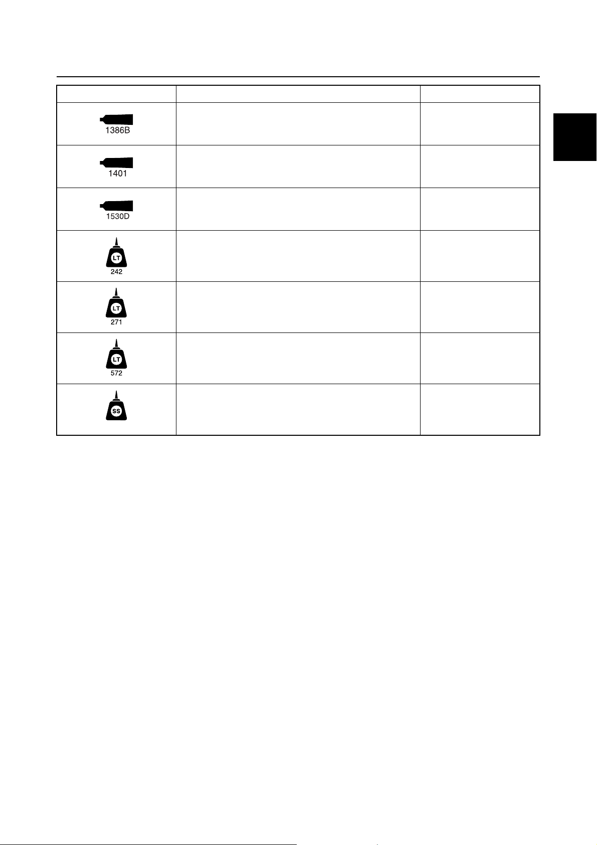
Symbols in an exploded diagram or illustration indicate the type of sealant or thread locking agent
and the application points.
Symbol Name Application
LOCTITE 518 Sealant
ThreeBond 1280B Sealant
Lubricant
Lubricant
Lubricant
0-7
ThreeBond 1303N Thread locking agent
ThreeBond 1322 Thread locking agent
ThreeBond 1324 Thread locking agent
ThreeBond 1377B Thread locking agent
Lubricant, sealant, and thread locking agent
Symbol Name Application
ThreeBond 1386B Sealant
ThreeBond 1401 Thread locking agent
ThreeBond 1530D Sealant
LOCTITE 242 (blue) Thread locking agent
LOCTITE 271 (red) Thread locking agent
LOCTITE 572 (white) Sealant
0
Silicone sealant Sealant
0-8
GEN
INFO
General information
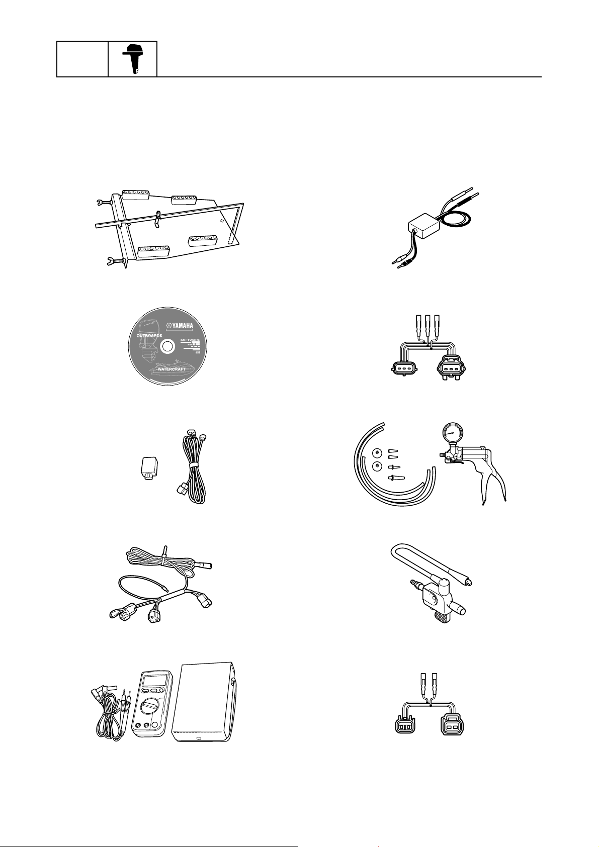
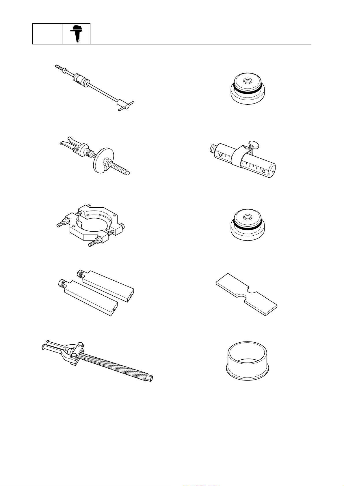
Special service tool
For all markets except U.S.A. and Canada
Special service tools with Yamaha part numbers (90890/60V-*****) are distributed by the Parts Division.
Drilling plate
90890-06783
YDIS (CD-ROM, Ver. 1.33)
60V-WS853-06
YDIS USB adapter and cable
60V-WS850-00
Peak voltage adapter
90890-03172
Test harness (3 pins)
90890-06869
Vacuum/pressure pump gauge set
90890-06756
Diagnostic flash indicator B
90890-06865
Digital circuit tester
90890-03174
0-9
Ignition tester
90890-06754
Test harness (2 pins)
90890-06867
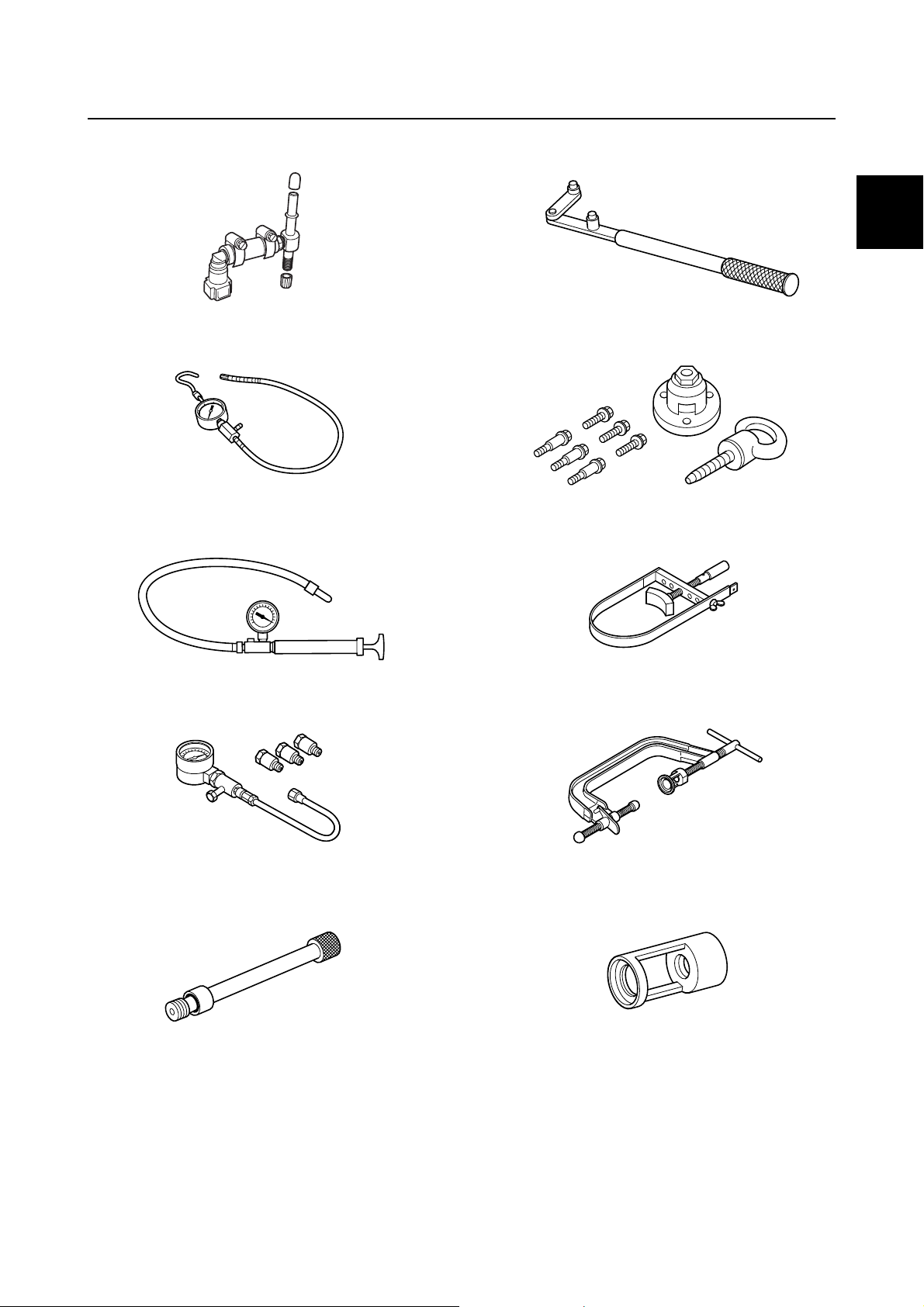
Special service tool
Fuel pressure gauge adapter B
90890-06942
Fuel pressure gauge
90890-06786
Leakage tester
90890-06840
Flywheel magnet holder
90890-06522
0
Flywheel puller
90890-06521
Sheave holder
90890-01701
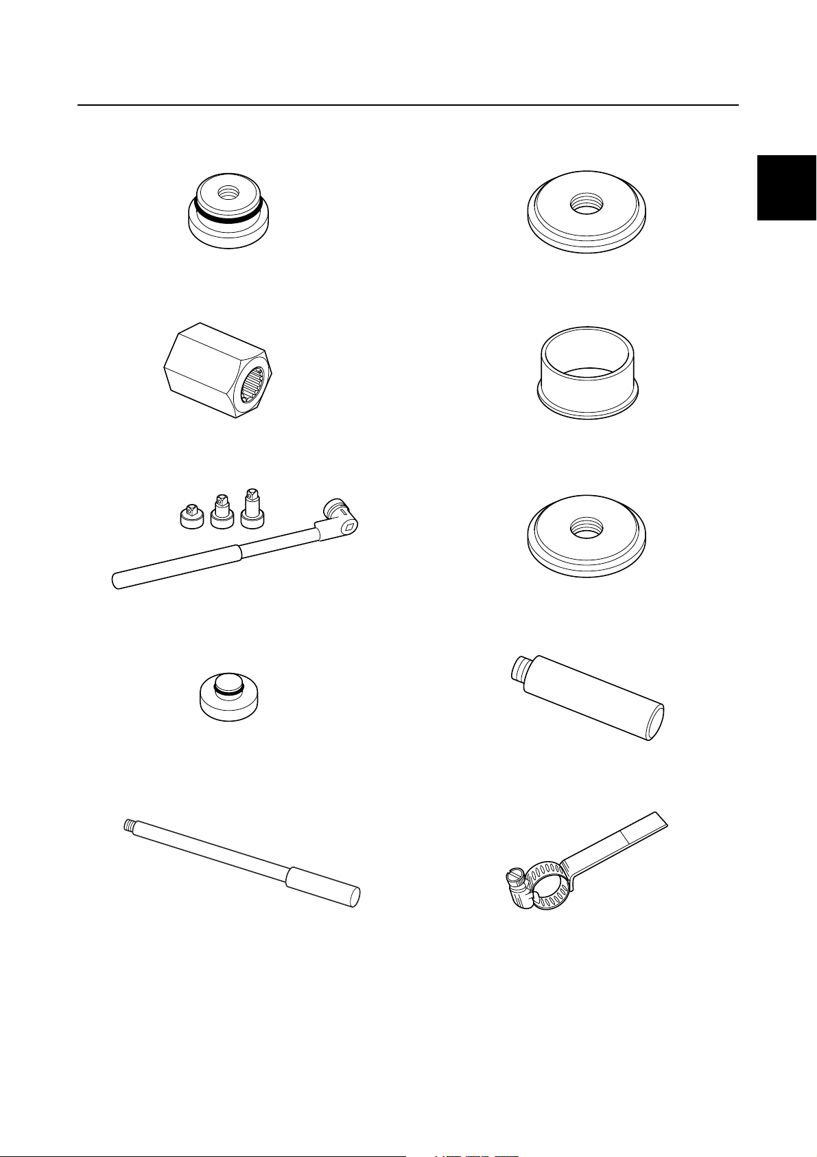
Compression gauge
90890-03160
Compression gauge extension
90890-06563
Valve spring compressor
90890-04019
Valve spring compressor attachment
90890-06320
0-10
GEN
INFO
General information
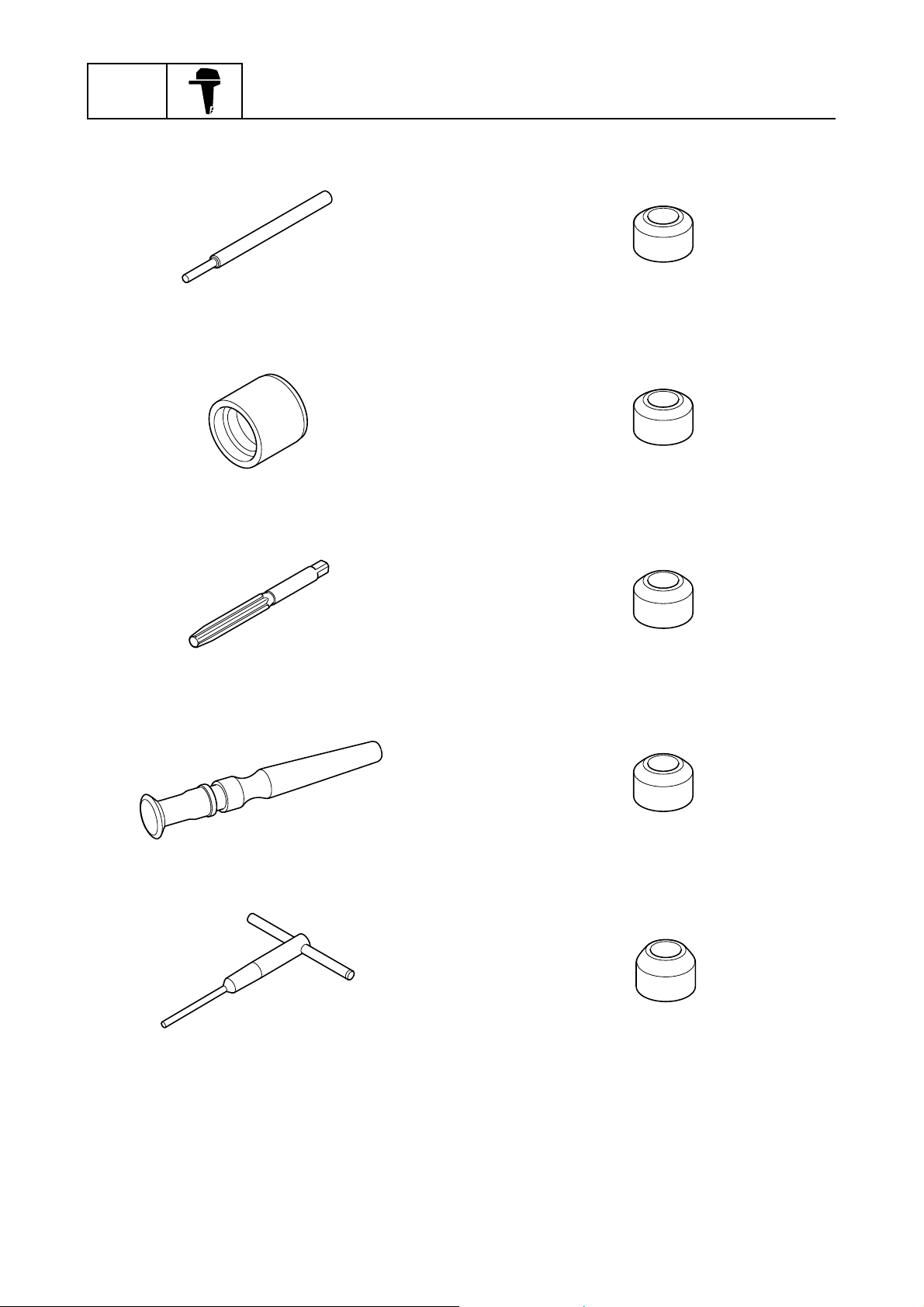
Valve guide remover/installer
90890-06801
Valve guide installer
90890-06810
Valve guide reamer
90890-06804
Valve seat cutter 30° (intake)
90890-06817
Valve seat cutter 30° (exhaust)
90890-06326
Valve seat cutter 45° (intake)
90890-06816
Valve lapper
90890-04101
Valve seat cutter holder
90890-06316
Valve seat cutter 45° (exhaust)
90890-06325
Valve seat cutter 60° (intake and exhaust)
90890-06324
0-11
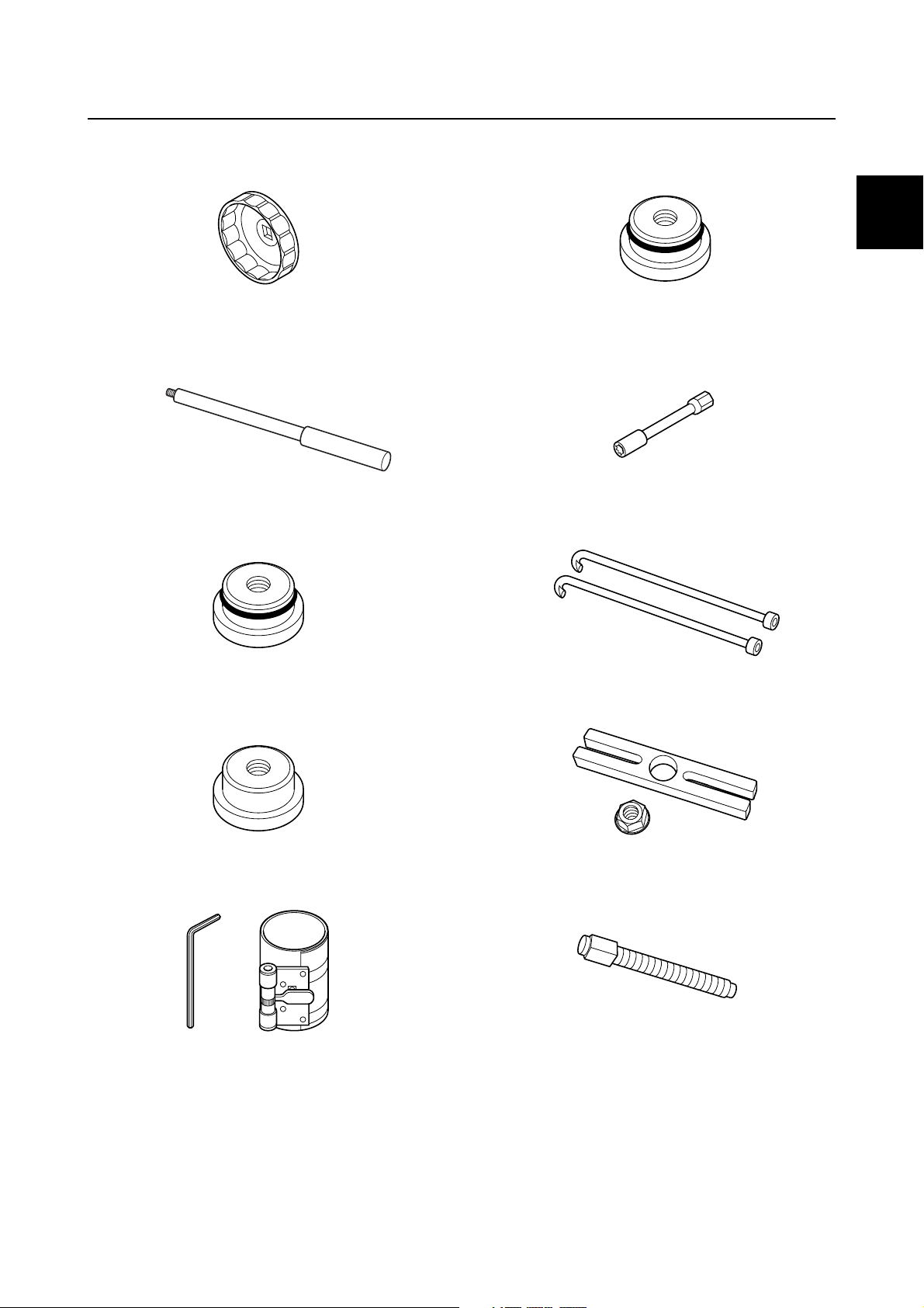
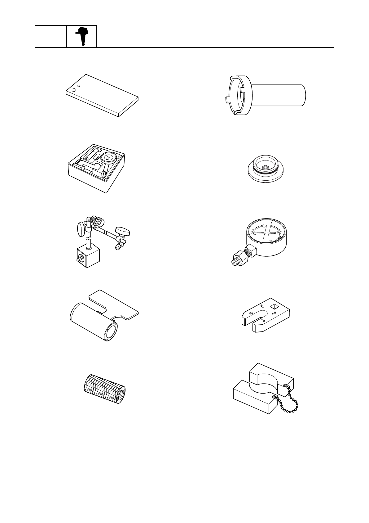
Special service tool
Oil filter wrench
90890-06830
Driver rod L3
90890-06652
Needle bearing attachment
90890-06613
Needle bearing attachment
90890-06653
0
Shift rod socket
90890-06679
Bearing housing puller claw L
90890-06502
Needle bearing attachment
90890-06607
Piston ring compressor
90890-05158
Stopper guide plate
90890-06501
Center bolt
90890-06504
0-12
GEN
INFO
General information
Slide hammer handle
90890-06531
Bearing outer race puller assembly
90890-06523
Bearing separator
90890-06534
Needle bearing attachment
90890-06611
Driver rod SS
90890-06604
Needle bearing attachment
90890-06610
Stopper guide stand
90890-06538
Bearing puller assembly
90890-06535
Bearing depth plate
90890-06603
Bearing inner race attachment
90890-06640
0-13
Special service tool
Needle bearing attachment
90890-06654
Drive shaft holder 6
90890-06520
Pinion nut holder
90890-06715
Bearing inner race attachment
90890-06658
0
Bearing inner race attachment
90890-06659
Bearing outer race attachment
90890-06628
Ball bearing attachment
90890-06655
Driver rod LL
90890-06605
Driver rod LS
90890-06606
Backlash indicator
90890-06706
0-14
GEN
INFO
General information
Magnet base plate
90890-07003
Dial gauge set
90890-01252
Magnet base B
90890-06844
Ring nut wrench
90890-06578
Ball bearing attachment
90890-06557
PTT oil pressure gauge assembly
90890-06580
Pinion height gauge
90890-06672
Puller head
90890-06514
Cylinder-end screw wrench
90890-06568
PTT piston vice attachment
90890-06572
0-15

Tilt rod wrench
90890-06569
Special service tool
0
0-16

SPEC
Specification
Model features.................................................................... 1-1
General feature .......................................................................... 1-1
Model designation ...................................................................... 1-2
Serial number ............................................................................. 1-3
Model data .......................................................................... 1-4
Dimension and weight ................................................................ 1-4
Performance............................................................................... 1-4
Power unit .................................................................................. 1-4
Lower unit................................................................................... 1-5
Bracket unit ................................................................................ 1-5
Fuel and oil requirement............................................................. 1-5
Battery requirement.................................................................... 1-6
PTT fluid requirement................................................................. 1-6
Electrical system technical data....................................... 1-7
Ignition timing control system ..................................................... 1-7
Fuel injection control system ...................................................... 1-8
Engine speed control system ..................................................... 1-8
VCT system................................................................................ 1-9
PTT system ................................................................................ 1-9
Charging system ...................................................................... 1-10
Starting system......................................................................... 1-10
Gauge/sensor........................................................................... 1-11
Fuel system technical data ............................................. 1-11
Fuel system .............................................................................. 1-11
Power unit technical data................................................ 1-12
Power unit ................................................................................ 1-12
Cylinder head assembly ........................................................... 1-12
Crankcase assembly ................................................................ 1-13
Lower unit technical data ................................................ 1-15
Lower unit assembly (regular rotation model) .......................... 1-15
Lower unit assembly (counter rotation model) ......................... 1-15
Bracket unit technical data ............................................. 1-16
PTT system .............................................................................. 1-16
Specified tightening torque............................................. 1-17
Rigging information .................................................................. 1-17
Fuel system .............................................................................. 1-17
Power unit ................................................................................ 1-17
Lower unit (regular rotation model) .......................................... 1-19

Lower unit (counter rotation model).......................................... 1-19
Bracket unit .............................................................................. 1-19
PTT unit.................................................................................... 1-20
General tightening torque ............................................... 1-21
1
SPEC
Specification
Model features
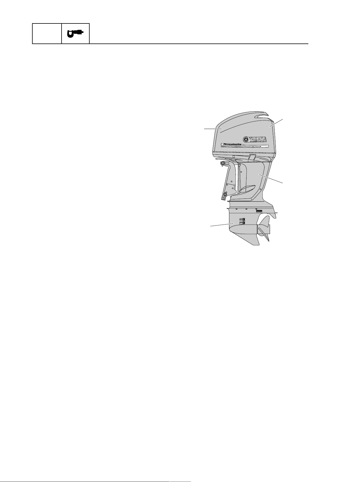
General feature
F200B, FL200B, F250G, and FL250G Overall feature
• Electronic fuel injected, 60° V6, DOHC, 24-valves, VCT, 3352.0 cm
• 6Y8 Multifunction Meter for easy rigging and precision engine information
• Low emission in compliance with EU regulation
a Power unit
• Shimless valve lifters
• Multi-point electronic fuel injection
• Blowby gas reburning system
• Vapor gas treatment system
• Single electronic throttle body
• Long intake manifolds
• Large diameter intake valve heads
• In-bank exhaust system
• Speed sensor and water pressure sensor
(optional)
b
3
(204.5 cu. in) engine
a
c
b Electrical
• Electronic fuel injection control
• Digital ignition control
• VCT control
• Knock control
• Over-rev control
• Self-diagnosis system
• ETV control
• Fail-safe control
• Conventional or LAN gauges acceptable
• Water-cooled Rectifier Regulator with isola-
tor
c Upper case
• Anodized exhaust passages
d Lower unit
• Hard chromeplated water pump (outer plate
cartridge and insert cartridge)
• Anodized lower case and propeller shaft
housing (F250G and FL250G)
• Drive shaft spring (F250G and FL250G)
• Propeller damper cooling system (F250G
and FL250G)
d
1-1

Model designation
F 250 G E T X
12 3 4 5
Model features
None: 2-stroke
E: Enduro
F: 4-stroke
1 Model category
2 Output horsepower Example: 6/9.9/75/150/250/300
3 Model generation A/B/C/D/F/G/H/J/L/N/P/Q/R/S/T/U/V/X/Y (Repeat from A)
4 Model variation
L: Counter rotating propeller
T: High thrust (4-stroke)
D: Twin rotating propeller
K: Kerosene
Z: HPDI
Level 1: Starting method
M: Manual start
E: Electric start
W: Electric start with manual start
Level 2: Control method
None: Remote control without tiller handle
H: Tiller handle
C: Remote control with tiller handle
Level 3: Trim and tilt method
None: Manual tilt
D: Hydraulic tilt
P: PT (Power tilt)
T: PT/T (Power trim and tilt)
1
Transom height
5
(Drive shaft length)
Level 4: Lubrication system (2-stroke model)
None: Premixed fuel with oil model
O: Oil injection model
S (15 in)
L (20 in)
Y (22.5 in)
X (25 in)
U (31 in)
1-2
SPEC
Specification
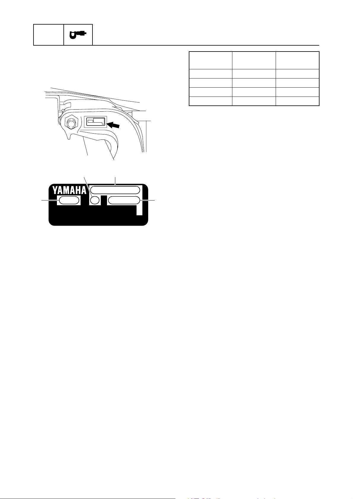
Serial number
The outboard motor serial number is indicated on a label affixed to the port clamp
bracket.
31
2
YAMAHA MOTOR CO., LTD.
MADE IN JAPAN
PAYS D'ORIGINE JAPON
4
Model name
Approved
model code
Starting
serial No.
F200BET 6S1 1002876–
FL200BET 6S2 1001074–
F250GET 6DX 1000001–
FL250GET 6DY 1000001–
1 Model name
2 Approved model code
3 Transom height
4 Serial number
1-3

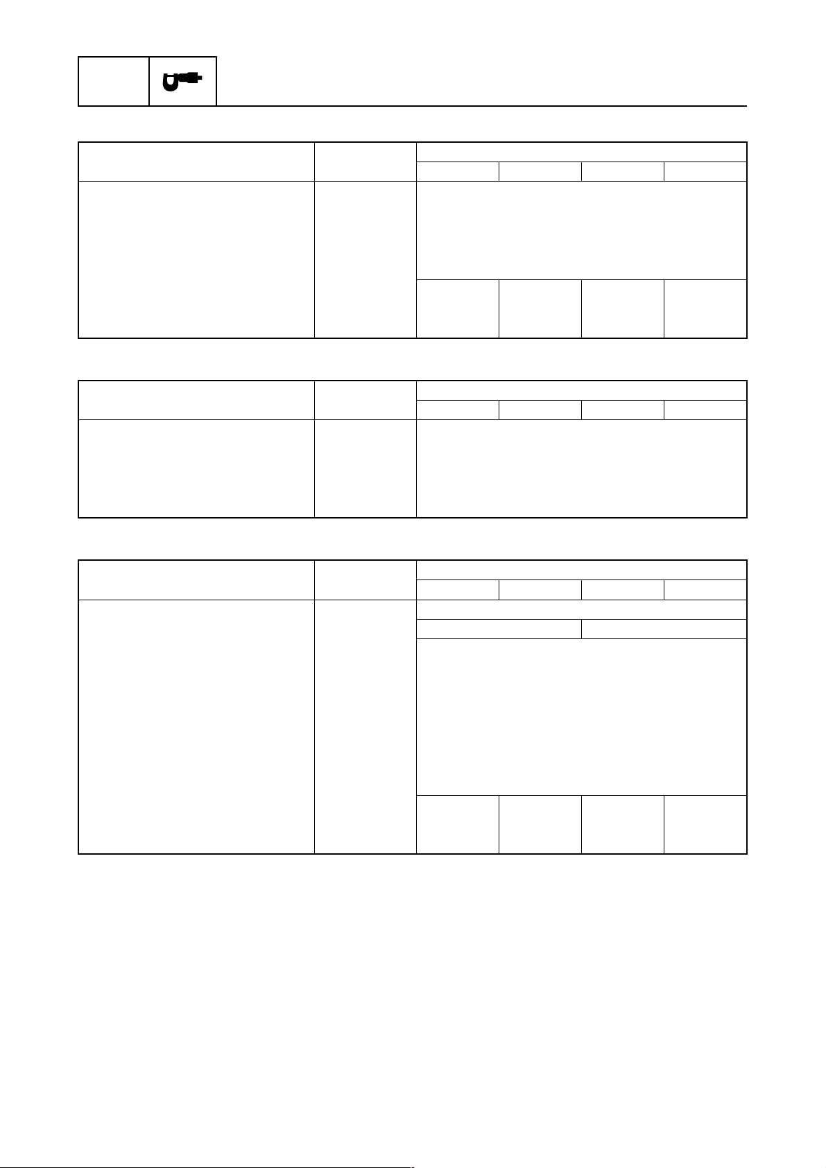
Model data
Dimension and weight
Model features / Model data
Item Unit
Overall length mm (in)
Overall width mm (in) 634.0 (25.0)
Overall height
X mm (in)
U mm (in) 1956.0 (77.0)
Outboard motor transom height
X mm (in) 643.0 (25.3)
U mm (in) 770.0 (30.3)
Weight (SUS)
X kg (lb) 283.0 (624)
U kg (lb) 290.0 (639)
(*1) With SUS (stainless steel) propeller
(*1)
F200BET FL200BET F250GET FL250GET
Model
868.0 (34.2)
1829.0 (72.0)
Performance
Item Unit
Maximum output
At 5500 r/ min kW (HP)
Full throttle operating range r/min
Maximum fuel consumption
At 5500 r/min
Engine idle speed r/min
L (US gal,
Imp gal)/hr
F200BET FL200BET F250GET FL250GET
147.1 (200)
73.7 (19.5, 16.2) 75.6 (20.0, 16.6)
Model
5000–6000
600–700
1
183.9 (250)
Power unit
Item Unit
Type 4-stroke, DOHC
Cylinder quantity V6
Total displacement cm
Bore × stroke mm (in) 94.0 × 80.5 (3.70 × 3.17)
Compression ratio 9.9 : 1
Control system Remote control
Starting system Electric
Fuel system Fuel injection
Ignition control system TCI
Advance type Microcomputer
Maximum generator output V, A 12.0, 44.0
Spark plug LFR6A-11(NGK)
Firing order 1–2–3–4–5–6 (Normal operation)
Cooling system Water
Exhaust system Propeller boss
Lubrication system Wet sump
3
(cu. in) 3352.0 (204.5)
F200BET FL200BET F250GET FL250GET
Model
1-4
SPEC
Lower unit
Specification
Item Unit
Gear shift positions F-N-R
Gear ratio 2.00 (30/15)
Reduction gear type Spiral bevel gear
Clutch type Dog clutch
Propeller shaft type Spline
Propeller direction (rear view)
Propeller mark T, M TL, ML T, M TL, ML
F200BET FL200BET F250GET FL250GET
Clock-
wise
Counter-
clockwise
Model
Clock-
wise
Counter-
clockwise
Bracket unit
Item Unit
Trim angle
At 12° boat transom degree –3 to 16
Tilt-up angle degree 70
Steering angle degree 32 + 32
Trim and tilt system PTT
F200BET FL200BET F250GET FL250GET
Model
Fuel and oil requirement
Item Unit
Fuel type Regular unleaded gasoline
Minimum fuel octane number RON 84 90
Engine oil 4-stroke motor oil
Engine oil grade (*1) (*2) API SE, SF, SG, SH, SJ, SL
SAE 5W-30, 10W-30, 10W-40
Total engine oil quantity (oil pan
capacity) (*3)
Gear oil type Hypoid gear oil
Gear oil grade (*2)
Gear oil quantity
(*1) If the recommended engine oil grades are not available, use engine oil with an API classifica-
tion of SH, SJ, or SL and an SAE classification of 15W-40, 20W-40, or 20W-50.
(*2) Meeting both API and SAE requirements.
(*3) For actual engine oil amount required at periodical oil check, see “Power unit technical data”
(1-12).
L (US qt,
Imp qt)
API GL-4
SAE 90
L (US qt,
Imp qt)
F200BET FL200BET F250GET FL250GET
1.150
(1.216,
1.012)
(1.057,
0.880)
Model
5.6 (5.92, 4.93)
1.000
(1.216,
1.012)
1.150
1.000
(1.057,
0.880)
1-5
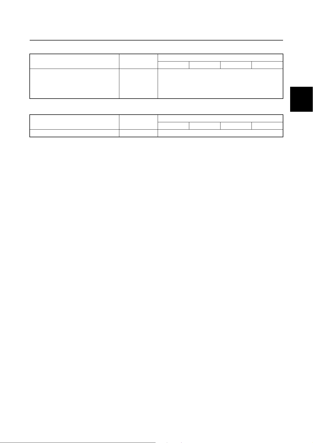
Battery requirement
Model data
Item Unit
Minimum cold cranking amps
CCA/EN A 711.0
Minimum rated capacity
20HR/IEC Ah 100.0
F200BET FL200BET F250GET FL250GET
Model
PTT fluid requirement
Item Unit
Fluid type ATF Dexron II
F200BET FL200BET F250GET FL250GET
Model
1
1-6

SPEC
Specification
Electrical system technical data
Ignition timing control system
Item Unit
Spark plug
Gap mm (in) 1.0–1.1 (0.039–0.043)
Ignition coil
Input voltage V 12.0
Pulser coil
Air gap mm (in) 1.4–1.6 (0.055–0.063)
Resistance (*1)
At 20 °C (68 °F) Ω 396.0–594.0
Output peak voltage
At cranking (unloaded) V 3.0
At cranking (loaded) V 2.7
At 1500 r/min (loaded) V 14.5
At 3500 r/min (loaded) V 17.8
Cam position sensor
Input voltage V 12.0
Knock sensor
Resistance (*1)
At 20 °C (68 °F) kΩ 504.0–616.0
Air temperature sensor
Resistance (*1)
At 20 °C (68 °F) kΩ 2.21–2.69
At 80 °C (176 °F) kΩ 0.32
Input voltage V 4.75–5.25
Neutral switch
Input voltage V 4.75–5.25
Air pressure sensor
Input voltage V 4.75–5.25
Output voltage
At –20.0 kPa (–0.20
kgf/cm
At –46.7 kPa (–0.467
kgf/cm
Engine temperature sensor
Resistance (*1)
At 20 °C (68 °F) kΩ 54.2–69.0
At 100 °C (212 °F) kΩ 3.12–3.48
Thermoswitch
Input voltage (*1) V 11.4
Temperature
Switch ON °C (°F) 84–90 (183–194)
Switch OFF °C (°F) 68–82 (154–180)
2
, –2.9 psi)
2
, –6.8 psi)
V3.21
V2.16
F200BET FL200BET F250GET FL250GET
Model
(*1) The figures are for reference only.
1-7
 Loading...