


F225A
FL225A
SERVICE MANUAL
290435
69J-28197-3D-11
NOTICE
This manual has been prepared by Yamaha primarily for use by Yamaha dealers and their trained
mechanics when performing maintenance procedures and repairs to Yamaha equipment. It has
been written to suit the needs of persons who have a basic understanding of the mechanical and
electrical concepts and procedures inherent in the work, for without such knowledge attempted
repairs or service to the equipment could render it unsafe or unfit for use.
Because Yamaha has a policy of continuously improving its products, models may differ in detail
from the descriptions and illustrations given in this publication. Use only the latest edition of this
manual. Authorized Yamaha dealers are notified periodically of modifications and significant
changes in specifications and procedures, and these are incorporated in successive editions of this
manual.
Microsoft and Windows are registered trademarks of Microsoft Corporation.
Important information
Particularly important information is distinguished in this manual by the following notations:
The Safety Alert Symbol means ATTENTION! BECOME ALERT! YOUR SAFETY IS
INVOLVED!
WARNING
Failure to follow WARNING instructions could result in severe injury or death to the machine
operator, a bystander, or a person inspecting or repairing the outboard motor.
CAUTION:
A CAUTION indicates special precautions that must be taken to avoid damage to the outboard motor.
NOTE:
A NOTE provides key information to make procedures easier or clearer.
1
F225A, FL225A
SERVICE MANUAL
©2001 by Yamaha Motor Co., Ltd.
1st Edition, June 2001
All rights reserved.
Any reprinting or unauthorized use
without the written permission of
Yamaha Motor Co., Ltd.
is expressly prohibited.
Printed in the Netherlands
Contents
General information
Specifications
Periodic checks and adjustments
Fuel system
Power unit
GEN
INFO
SPEC
CHK
ADJ
FUEL
POWR
1
2
3
4
5
Lower unit
Bracket unit
Electrical systems
Troubleshooting
Index
LOWR
BRKT
–+
ELEC
TRBL
SHTG
6
7
8
9

GEN
INFO
General information
How to use this manual.................................................................................1-1
Manual format............................................................................................1-1
Symbols.....................................................................................................1-2
Safety while working......................................................................................1-3
Fire prevention...........................................................................................1-3
Ventilation..................................................................................................1-3
Self-protection ...........................................................................................1-3
Parts, lubricants, and sealants ..................................................................1-3
Good working practices .............................................................................1-4
Disassembly and assembly .......................................................................1-4
Identification...................................................................................................1-5
Applicable models .....................................................................................1-5
Serial number ............................................................................................1-5
Features and benefits....................................................................................1-6
Newly developed V6 4-stroke engine........................................................1-6
Valve train system .....................................................................................1-9
Intake system ..........................................................................................1-11
Exhaust system .......................................................................................1-11
Fuel system .............................................................................................1-13
PTT (Power trim and tilt) unit...................................................................1-17
Technical tips ...............................................................................................1-18
Fuel injection control................................................................................1-18
Fail-safe function table ............................................................................1-20
PTT (Power trim and tilt) unit...................................................................1-21
Cooling system ........................................................................................1-26
Lubrication system...................................................................................1-26
Propeller selection.......................................................................................1-27
Propeller size...........................................................................................1-27
Selection..................................................................................................1-27
69J3D11

Predelivery checks ......................................................................................1-28
Checking the fuel system ........................................................................1-28
Checking the gear oil...............................................................................1-28
Checking the engine oil ...........................................................................1-28
Checking the battery................................................................................1-28
Checking the outboard motor mounting height........................................1-29
Checking the remote control cables ........................................................1-29
Checking the steering wheel ...................................................................1-30
Checking the gearshift and throttle operation..........................................1-30
Checking the tilt system...........................................................................1-30
Checking the engine start switch and engine stop switch/
engine shut-off switch ............................................................................1-30
Checking the cooling water pilot hole ......................................................1-31
Test run ...................................................................................................1-31
Break-in ...................................................................................................1-31
After test run ............................................................................................1-31
1
2
3
4
5
6
7
8
9
69J3D11
GEN
INFO
General information
How to use this manual
Manual format
The format of this manual has been designed to make service procedures clear and easy to understand. Use the information below as a guide for effective and quality service.
1
Parts are shown and detailed in an exploded diagram and are listed in the components list.
2
Tightening torque specifications are provided in the exploded diagrams and after a numbered
step with tightening instructions.
3
Symbols are used to indicate important aspects of a procedure, such as the grade of lubricant
and lubrication point.
4
The components list consist of parts and part quantities, as well as bolt, screw, O-ring, and hose
dimensions.
5
Service points regarding removal, checking, and installation are shown in individual illustrations
to explain the relevant procedure.
NOTE:
For troubleshooting procedures, see Chapter 9, “Troubleshooting.”
1
1-1
69J3D11
T
R
.
.
How to use this manual
Symbols
The symbols below are designed to indicate the content of a chapter.
General information
GEN
INFO
Specifications
SPEC
Periodic checks and adjustments
CHK
ADJ
Symbols 1 to 6 indicate specific data.
123456
Fuel system
FUEL
Power unit
POWR
Lower unit
LOWR
Bracket unit
BRKT
Electrical systems
ELEC
Troubleshooting
– +
TRBL
SHTG
1
2
3
4
Special tool
1
Specified oil or fluid
2
Specified engine speed
3
Specified tightening torque
4
Symbols 7 to A in an exploded diagram indicate the grade of lubricant and the lubrication point.
7890A
A M
E
Apply Yamaha 4-stroke motor oil
7
Apply water resistant grease (Yamaha grease A)
8
Apply molybdenum disulfide grease
9
Symbols B to G in an exploded diagram indicate the type of sealant or locking agent and the application point.
BCDEFG
GM
4
LT
271
Specified measurement
5
Specified electrical value
6
(resistance, voltage, electric current)
D C
Apply corrosion resistant grease
0
(Yamaha grease D)
Apply low temperature resistant grease
A
(Yamaha grease C)
LT
242
LT
572
SS
5
6
7
8
9
®
Apply Gasket Maker
B
Apply Yamabond No. 4
C
Apply LOCTITE
D
69J3D11
®
No. 271 (Red)
Apply LOCTITE
E
Apply LOCTITE
F
Apply silicon sealant
G
®
No. 242 (Blue)
®
No. 572
1-2
GEN
INFO
General information
Safety while working
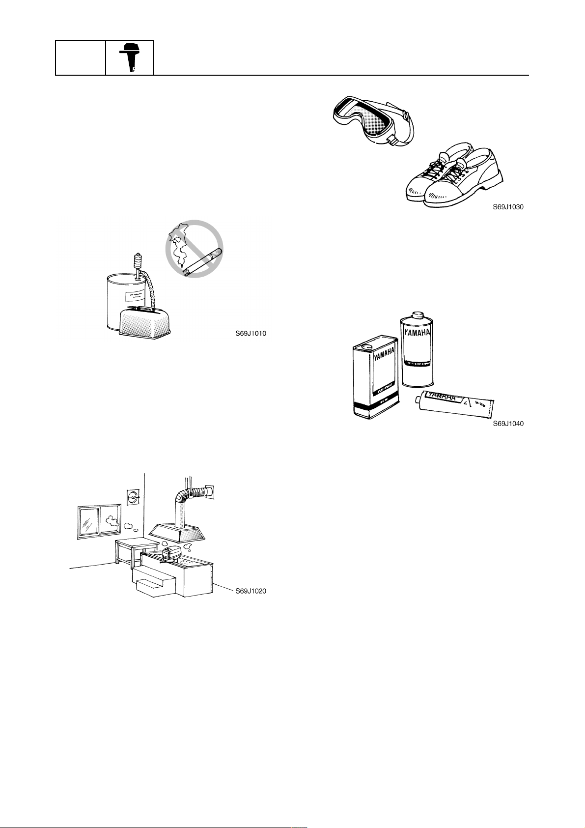
To prevent an accident or injury and to
ensure quality service, follow the safety procedures provided below.
Fire prevention
Gasoline is highly flammable.
Keep gasoline and all flammable products
away from heat, sparks, and open flames.
Ventilation
Gasoline vapor and exhaust gas are heavier
than air and extremely poisonous. If inhaled
in large quantities they may cause loss of
consciousness and death within a short time.
When test running an engine indoors (e.g., in
a water tank) be sure to do so where adequate ventilation can be maintained.
1
Parts, lubricants, and sealants
Use only genuine Yamaha
and sealants or those recommended by
Yamaha, when servicing or repairing the
outboard motor.
Under normal conditions, the lubricants mentioned in this manual should not harm or be
hazardous to your skin. However, you should
follow these precautions to minimize any risk
when working with lubricants.
parts, lubricants,
Self-protection
Protect your eyes by wearing safety glasses
or safety goggles during all operations involving drilling and grinding, or when using an air
compressor.
Protect your hands and feet by wearing protective gloves and safety shoes when necessary.
1-3
1. Maintain good standards of personal and
industrial hygiene.
2. Change and wash clothing as soon as
possible if soiled with lubricants.
3. Avoid contact with skin. Do not, for
example, place a soiled rag in your
pocket.
4. Wash hands and any other part of the
body thoroughly with soap and hot water
after contact with a lubricant or lubricant
soiled clothing has been made.
5. To protect your skin, apply a protective
cream to your hands before working on
the outboard motor.
69J3D11
Safety while working
6. Keep a supply of clean, lint-free cloths for
wiping up spills, etc.
Good working practices
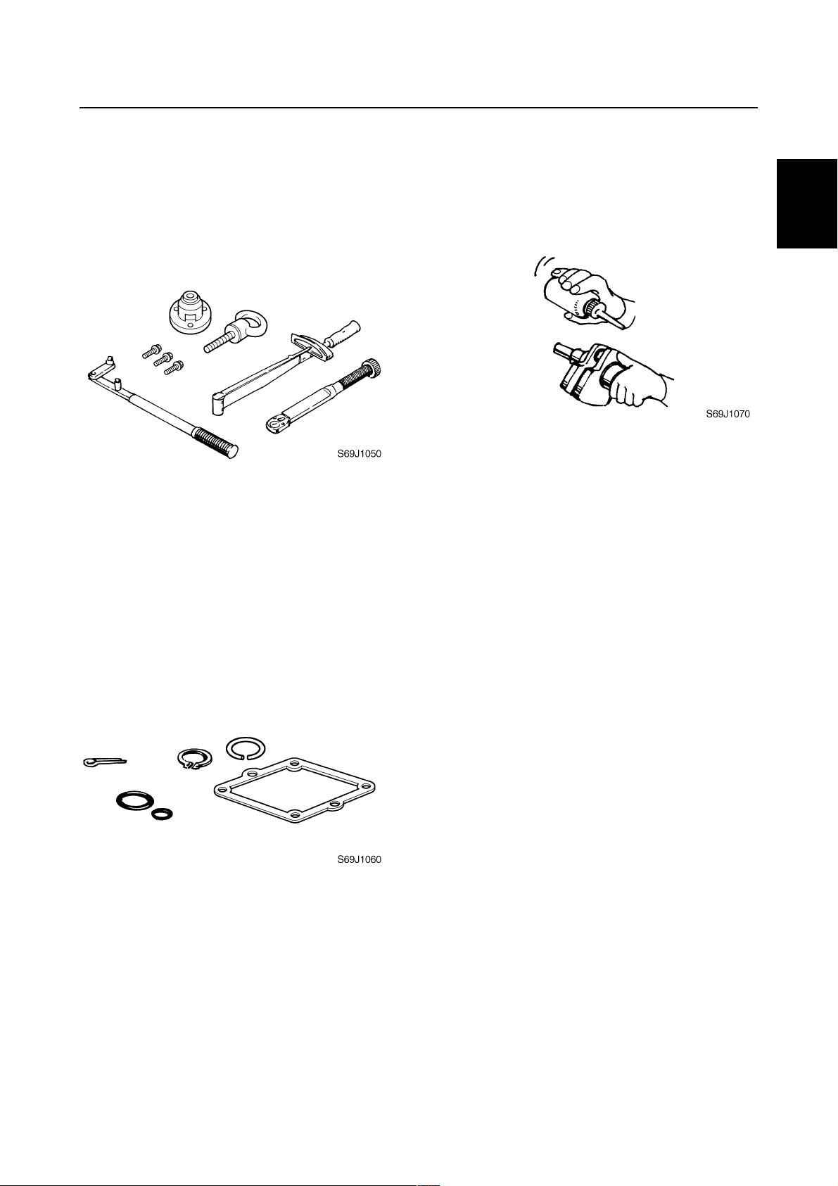
Special tools
Use the recommended special tools to protect parts from damage. Use the right tool in
the right manner—do not improvise.
Tightening torques
Follow the tightening torque specifications
provided throughout the manual. When tightening nuts, bolts, and screws, tighten the
large sizes first, and tighten fasteners starting
in the center and moving outward.
Non-reusable parts
Always use new gaskets, seals, O-rings, cotter pins, circlips, etc., when installing or
assembling parts.
Disassembly and assembly
1. Use compressed air to remove dust and
dirt during disassembly.
2. Apply engine oil to the contact surfaces
of moving parts before assembly.
3. Install bearings with the manufacture
identification mark in the direction indicated in the installation procedure. In
addition, be sure to lubricate the bearings
liberally.
4. Apply a thin coat of water-resistant
grease to the lip and periphery of an oil
seal before installation.
5. Check that moving parts operate normally after assembly.
1
2
3
4
5
6
7
8
9
69J3D11
1-4
GEN
INFO
General information
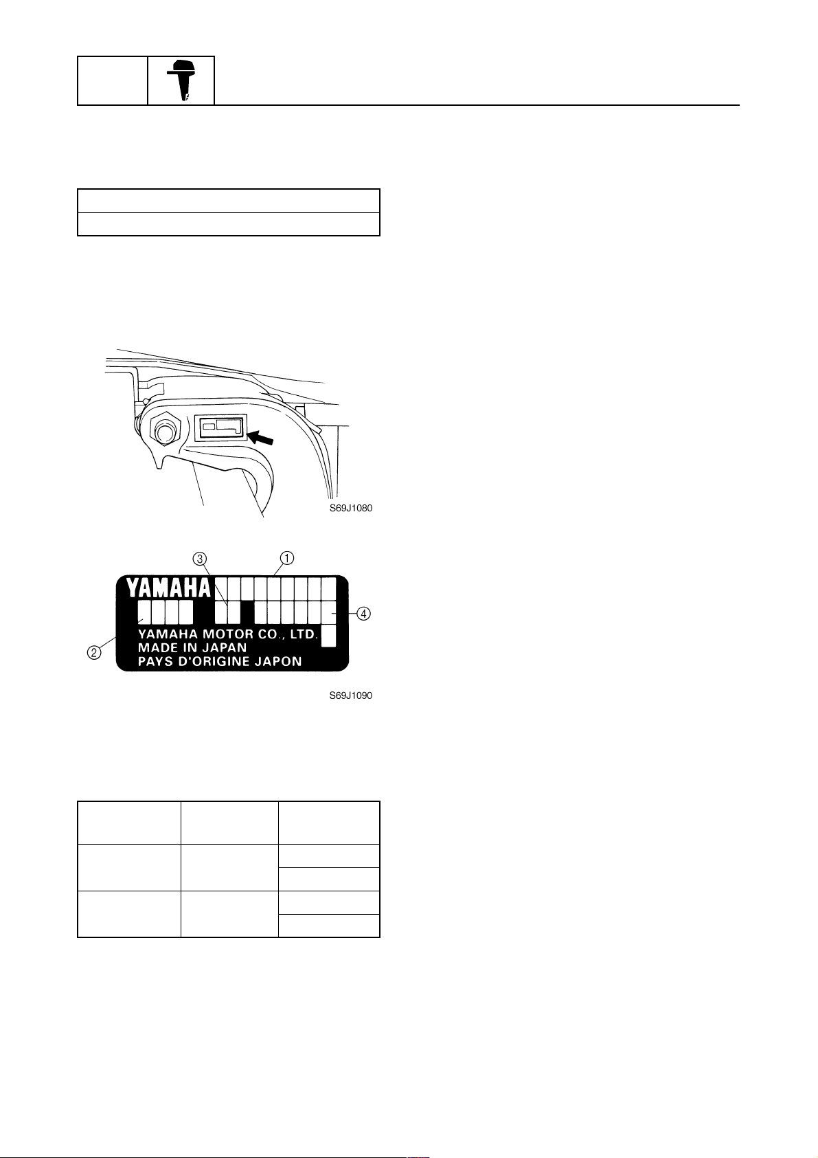
Identification
Applicable models
This manual covers the following models.
Applicable models
F225AET, FL225AET
Serial number
The outboard motor serial number is
stamped on a label attached to the port
clamp bracket.
1
Model name
1
Approved model code
2
Transom height
3
Serial number
4
Model name
Approved
model code
F225AET 69J
FL225AET 69K
1-5
Starting
serial No.
X: 000101–
U: 150101–
X: 000101–
U: 100101–
69J3D11
Identification / Features and benefits
Features and benefits
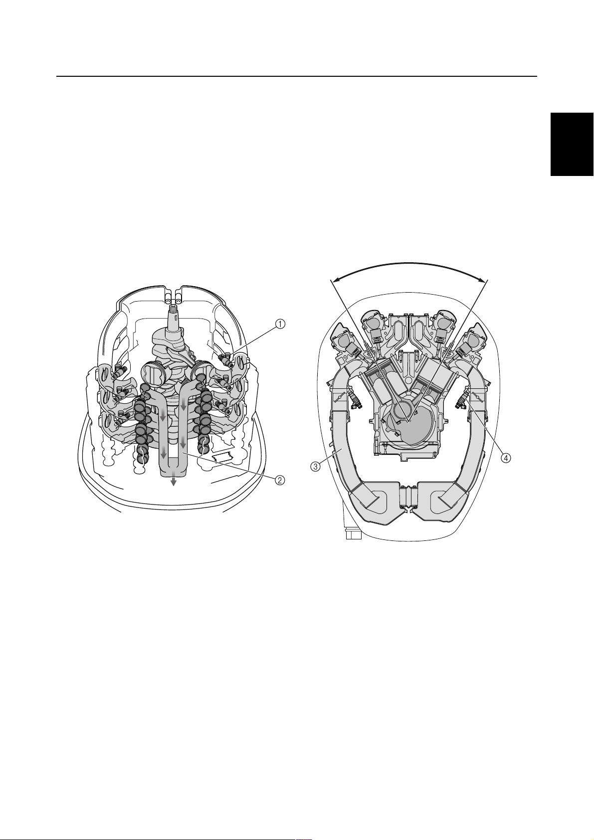
Newly developed V6 4-stroke engine
The F225 is a newly developed 60-degree V6 4-stroke engine with a very compact and lightweight
design. Its size and weight are almost the same as the V6 2-stroke engines that are in current use.
This F225 offers numerous advantages of a 4-stroke engine. Compared to conventional 2-stroke
models, it emits much cleaner exhaust gases, offers a better fuel economy, and realizes lower noise
levels at idle and full throttle.
Through the newly developed “In-bank exhaust system,” which discharges exhaust gases from the
center of both banks, the engine block and the surrounding equipment have been made compact. In
addition, the six independent intake passages help to achieve a high level of driveability and power
output.
60˚
1
1
2
3
4
Electronic Fuel Injection
1
In-bank exhaust system
2
Pulse tuned long intake tracks
3
Individual inside track fuel injectors
4
5
6
S69J1250
7
8
9
69J3D11
1-6
GEN
INFO
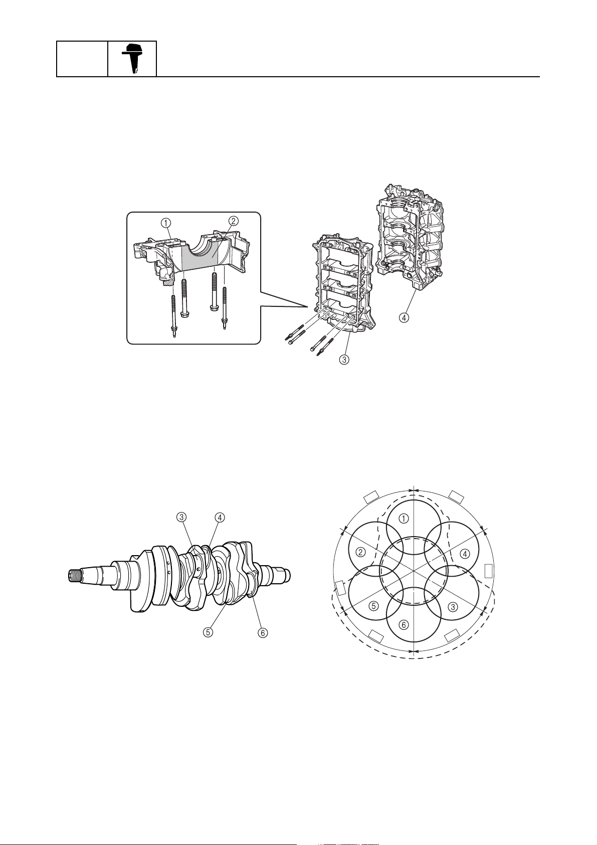
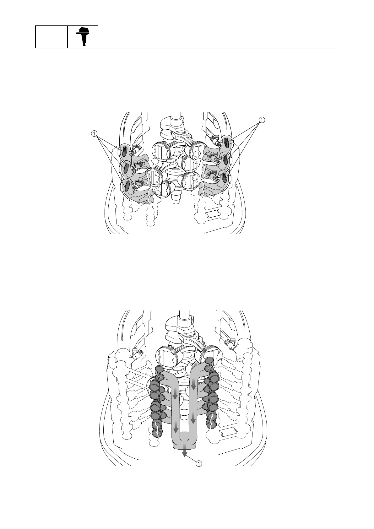
Crankcase
The crankcase is made of cast aluminum, however steel has been cast into the areas for the crankshaft bearings. By distinguishing the area that requires strength from the area that allows the use of
a lighter material, both weight reduction and a stronger construction have been achieved.
The caps for the crankshaft bearings are secured with four bolts to ensure a high level of assembled
rigidity.
General information
S69J1260
Casted aluminum
1
Steel
2
Crankcase
3
Cylinder block
4
Crankshaft
The crankshaft has been forged to realize a high-strength and high-rigidity construction. In the 60degree V6 cylinder configuration, the crankshaft pins are staggered 60 degrees from each other.
60˚
60˚
60˚
60˚
60˚
60˚
Crankpin #1
1
Crankpin #2
2
Crankpin #3
3
1-7
Crankpin #4
4
Crankpin #5
5
Crankpin #6
6
S69J1270
69J3D11
Features and benefits
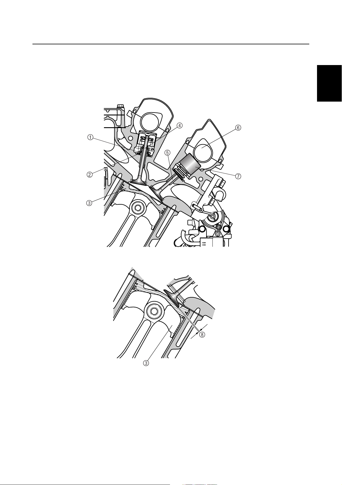
Piston
The piston has been carved out of a forged stock. To prevent the valves from coming in contact with
the piston, the piston is provided with a valve recess. If the engine goes out of timing and a valve
opens when the piston is at top-dead-center, this recess prevents the valve from coming in contact
with the piston, thus preventing engine damage.
1
2
3
S69J1280
4
5
6
7
8
Valve spring
1
Valve seal
2
Piston
3
Valve stem
4
69J3D11
Intake valve
5
Intake camshaft
6
Valve lifter
7
Valve recess
8
9
1-8
GEN
INFO
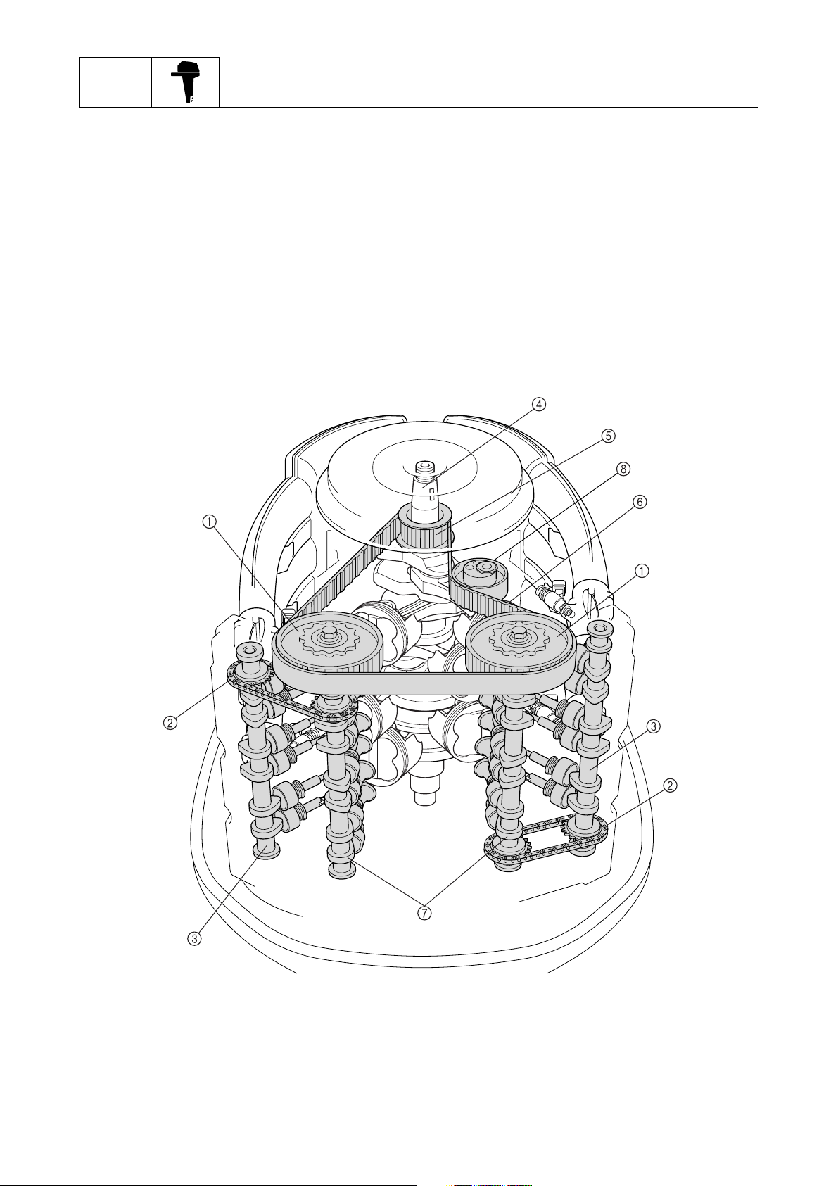
Valve train system
The valve train consists of a total of four camshafts, with two in each bank.
The camshafts are driven with the combination of a belt and chains. The crankshaft turns the belt to
drive the exhaust camshafts in both banks. Chains connect the exhaust camshafts to the intake
camshafts in the cylinder heads to drive the intake camshafts.
In addition, the timing belt offers quieter operation, and the cam chains help to achieve a compact
configuration through the use of individual driven sprockets.
Timing belt
The timing belt, which is driven by the drive sprocket that is attached to the crankshaft, rotates the
driven sprockets that are attached to the exhaust camshafts of both banks. The drive sprocket for
the timing belt is secured to the crankshaft by four bolts, and it can be removed easily for servicing.
In addition, the material of the driven sprockets has been changed from the previous metal to plastic
for weight reduction.
General information
Driven sprocket
1
Timing chain
2
Intake camshaft
3
Crankshaft
4
Drive sprocket
5
1-9
Timing belt
6
Exhaust camshaft
7
Hydraulic timing belt tensioner
8
S69J1290
69J3D11
Features and benefits
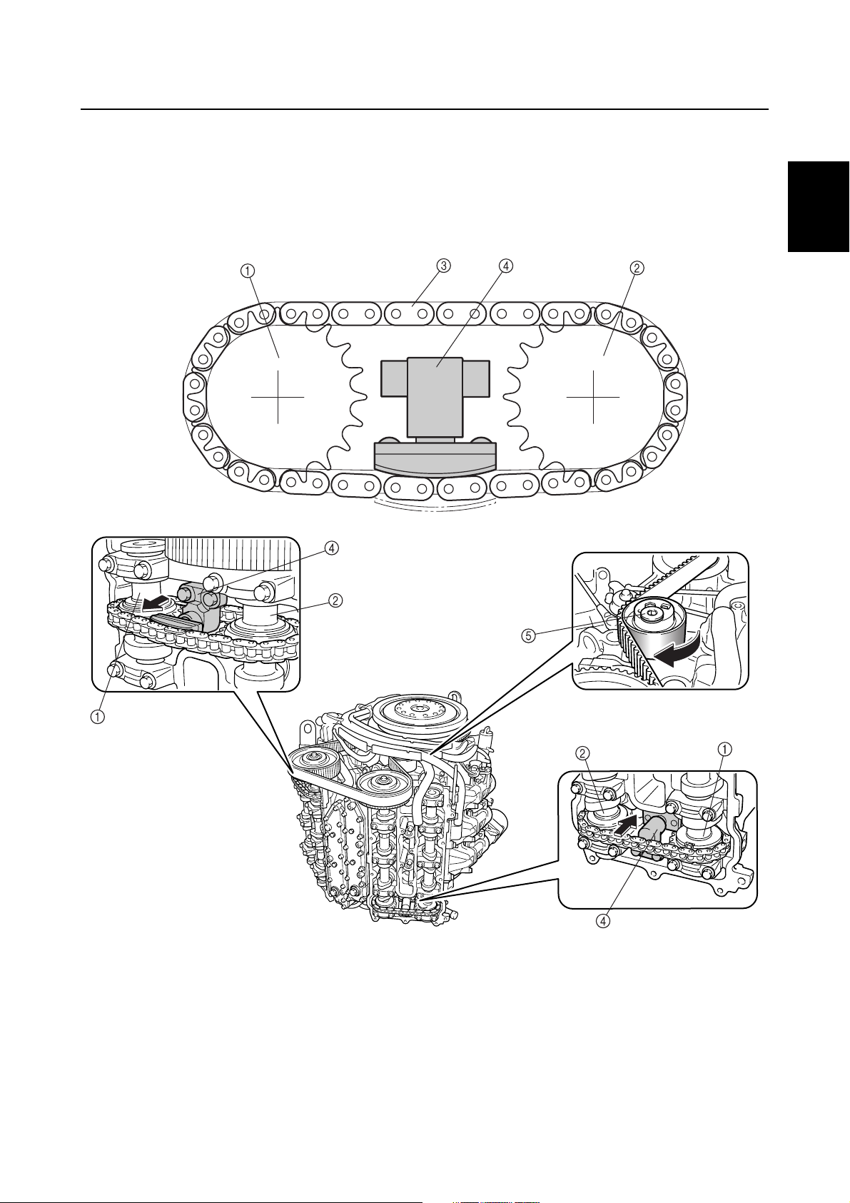
Tensioner
A timing chain tensioner is provided at the mid-span of the timing chain, between both camshafts.
The timing chain tensioner uses the force of a spring to maintain its tension. After the engine is
started, oil is pumped into the tensioner, and the resulting pressure causes the tension to increase.
A total of three tensioners are used, one for the timing belt, and one for each timing chain of both
banks, to maintain proper tension and to ensure the reliability of the valve train.
1
2
3
S69J1300
4
5
6
7
8
Intake camshaft
1
Exhaust camshaft
2
Timing chain
3
Timing chain tensioner
4
Hydraulic timing belt tensioner
5
69J3D11
9
1-10
GEN
INFO
Intake system
Throttle valve
A total of six intake throttle valves are provided, one for each cylinder. Together with the intake
silencer that offers enhanced intake efficiency and the injectors that are provided at each throttle
body, the throttle valves help to improve the intake efficiency of the engine. As a result, this engine
produces a higher power output and realizes better driveability.
General information
S69J1310
Throttle valve
1
Exhaust system
In-bank exhaust system
The exhaust passage of the F225 is located in the V bank, a layout that is the opposite of conventional V6 engines. By providing the exhaust passage in the V bank, the engine has been made considerably more compact.
Exhaust gas
1
1-11
S69J1320
69J3D11
Features and benefits
Exhaust passage during idle
To reduce noise when the engine is idling, the exhaust gas passage of the F225 has adopted a labyrinth construction. During idling, the exhaust gas passes through the passage on the side of the
exhaust guide, and enters the upper case through a hole in the upper case gasket. When it fills the
upper case, the exhaust gas enters another passage on the side of the exhaust guide through
another hole in the upper case gasket. Then, it is discharged through the idle port that is provided in
the upper case.
The exhaust manifold and muffler in the upper case are surrounded by the water jackets to reduce
exhaust noise. The water jackets also help prevent corrosion by preventing the exterior of the
exhaust manifold and muffler from coming in direct contact with the exhaust gas.
1
2
3
S69J1330
4
5
6
7
8
Idle port
1
Oil pan
2
Exhaust manifold
3
Muffler
4
Exhaust gas
È
Water
É
69J3D11
9
1-12
GEN
INFO
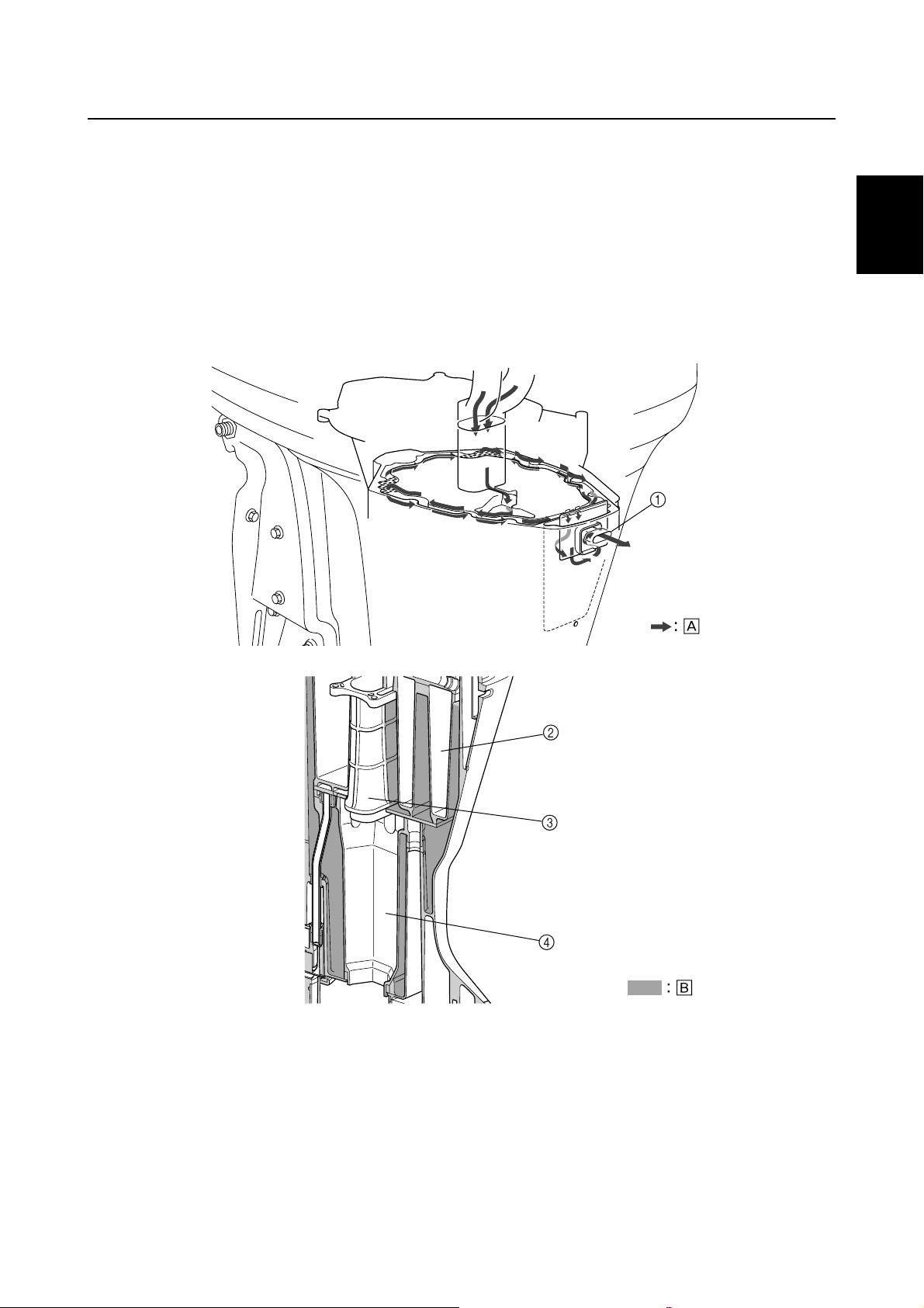
Fuel system
The fuel flows in the following order: fuel filter, low-pressure fuel pump, vapor separator, high-pressure fuel pump, and injectors. The excess fuel at the injectors passes through the pressure regulator and fuel cooler, and returns to the vapor separator.
When the engine start switch is turned on, the injectors of all cylinders operate before the pump
relay is actuated to prevent the injectors from sticking.
General information
Fuel filter
1
Low-pressure fuel pump
2
Vapor separator
3
High-pressure fuel pump
4
1-13
Fuel injector
5
Pressure regulator
6
Fuel cooler
7
S69J1340
69J3D11
Features and benefits
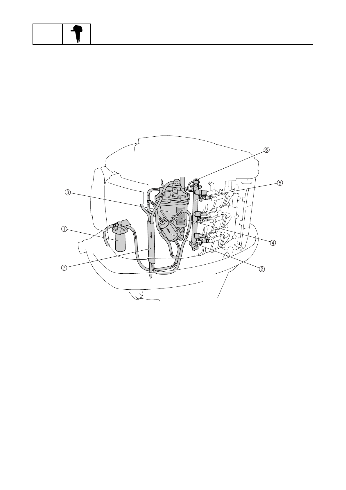
Low-pressure fuel pump
The F225 has adopted a newly developed, low-pressure electrical fuel pump, in place of the lowpressure mechanical fuel pump used in the previous electronic fuel injection system. With the adoption of the electric pump, the routing of the fuel system has been made more compact. To prevent
the over-pumping of fuel, this pump operates for 10 seconds, and stops for 20 seconds when the
engine is operating at low speeds.
The pump operates constantly if the engine speed is 1,200 r/min or higher, or for several seconds
(which vary by ambient temperature) after the engine is started. At other times, it operates for 10
seconds, and stops for 20 seconds to prevent over-pumping.
1
2
3
Vapor separator
1
Low-pressure fuel pump
2
Fuel filter
3
On
4
Off
5
10 seconds
6
20 seconds
7
S69J1350
4
5
6
7
8
69J3D11
9
1-14
GEN
INFO
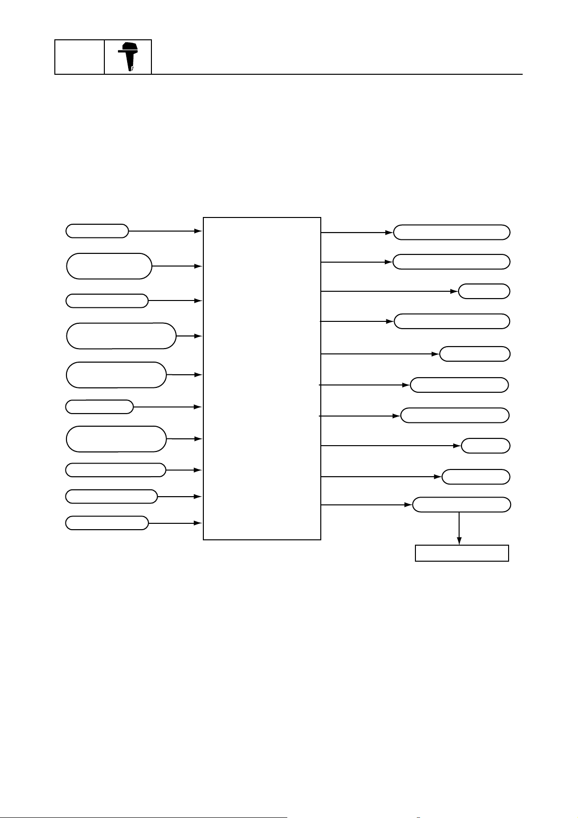
Electronic control system
The ECM of the F225 controls the ignition timing, the fuel injection timing, the fuel injection volume,
and the ISC and it maintains a stoichiometric air-fuel ratio in all operating conditions, including starting and idling. Also, the ECM converts the signals from the input sensors and sends instructions to
each part.
General information
Pulser coil
Throttle position
sensor
Thermo switch
Intake air temperature
sensor
Intake air pressure
sensor
Stop switch
Engine temperature
sensor
Oil pressure sensor
Shift cutoff switch
ECM
(Electronic
control
module)
Low-pressure fuel pump
High-pressure fuel pump
Injectors
ISC (Idle speed control)
Ignition coils
Overheat monitor
Oil pressure monitor
Buzzer
Tachometer
Diagnostic system
Neutral switch
1-15
Personal computer
S69J1360
69J3D11
Ignition and fuel injection timing
Firing order : #1, #2, #3, #4, #5, #6
Injection order : #1 and #4 → #2 and #5 → #3 and #6 (group injection)
Features and benefits
Cylinder
Cylinder #1
Cylinder #2
Cylinder #3
Ignition
Injection
Ignition
Injection
Ignition
Injection
Crankshaft angle
180˚
120˚
Compression
Intake
Intake
TDC
Compression
720˚
Combustion Exhaust
Combustion Exhaust
TDC
Compression
TDC
: Ignition spark
: Wasted spark
Intake
Combustion Exhaust
1
2
3
4
5
Cylinder #4
Ignition
Injection
Cylinder #5
Ignition
Injection
Cylinder #6
Ignition
Injection
Exhaust
Combustion Exhaust
Combustion Exhaust
Intake
Intake
Compression
Intake
Combustion
TDC
Compression
6
TDC
7
Compression
8
S69J1370
9
69J3D11
1-16
GEN
INFO
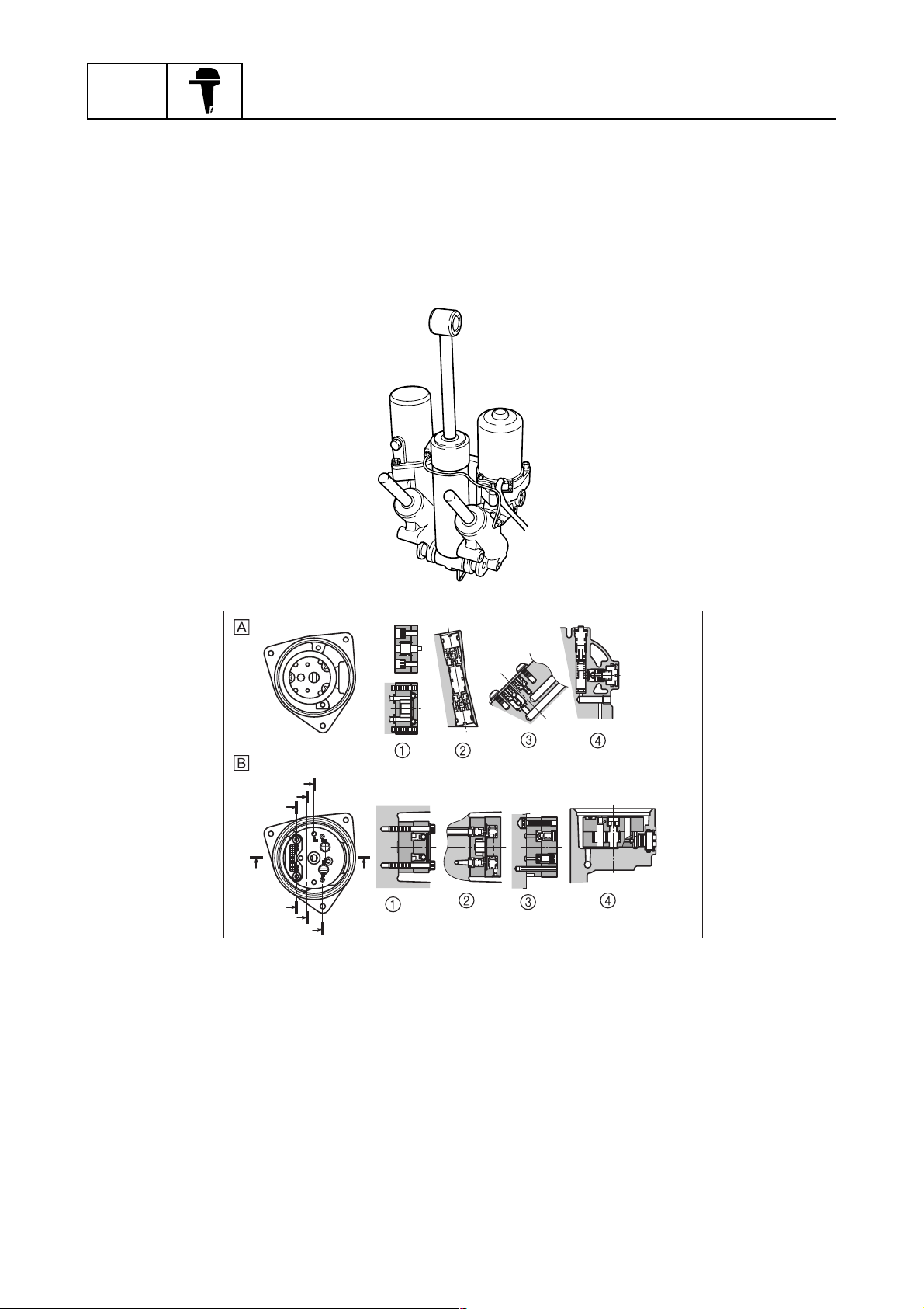
PTT (Power trim and tilt) unit
The PTT unit has been newly developed for the F225. Based on the field-proven 61A type, its PTT
fluid passage and internal valve construction have been changed for this application. Although the
valves of the 61A type have been distributed to the various areas of the gear pump housing, the
valves of the new PTT unit have been concentrated in the vicinity of the gear pump to improve their
serviceability. In addition, the material of the gear pump housing has been changed to enhance its
corrosion resistance.
General information
Gear pump
1
Main valve
2
Relief valve
3
C
B
A
DD
A
B
C
(A)
(B)
Manual valve
4
61A type
È
F225 type
É
(C)
(D)
S69J1380
1-17
69J3D11
Features and benefits / Technical tips
Technical tips
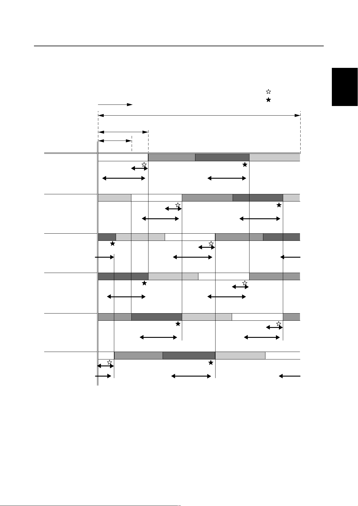
Fuel injection control
The F225 injects fuel simultaneously to the following cylinder pairs: #1 and #4, #2 and #5, and #3
and #6. Optimal injection timing is provided in accordance with the operating conditions of the
engine.
Starting fuel injection volume and injection timing
The injectors are actuated in sync with the standard crankshaft position signals (BTDC 70°) for cylinder pairs #1 and #4, #2 and #5, and #3 and #6, respectively.
(Compression TDC)
CYLINDER #1
CYLINDER #2
CYLINDER #3
CYLINDER #4
CYLINDER #5
CYLINDER #6
SIGNAL #1/4
SIGNAL #2/5
SIGNAL #3/6
INJECTION #1/4
INJECTION #2/5
INJECTION #3/6
#6
Compression Combustion Exhaust Intake Compression Expansion
Intake
Exhaust
Combustion Exhaust
B70
#1 #2 #3 #4 #5 #6 #1 #2
Compression Combustion Exhaust Intake Compression
Intake
Combustion Exhaust
B10 B70 B10
Intake
B70 B10
Compression
Intake
B70 B10B10 B70 B10
Combustion Exhaust Intake Compression
Compression Combustion Exhaust
Compression Combustion Exhaust
Intake
Compression Combustion Exhaust
B70 B10
B70 B10
Intake
B70 B10
1
1
2
3
4
Starting injection start timing
(standard position BTDC 70
˚)
S69J1390
Normal fuel injection volume and injection timing
To control the actuation timing of the injectors, the injection ending timing is established by using the
top-dead-center of the intake stroke as the standard, for cylinder pairs #1 and #4, #2 and #5, and #3
and #6, respectively.
(Compression TDC)
CYLINDER #1
CYLINDER #2
CYLINDER #3
CYLINDER #4
CYLINDER #5
CYLINDER #6
SIGNAL #1/4
SIGNAL #2/5
SIGNAL #3/6
INJECTION #1/4
INJECTION #2/5
INJECTION #3/6
Synchronous injection completion timing
#6
Compression Combustion Exhaust Intake Compression Expansion
Intake
Exhaust
Combustion Exhaust
B70
B10 B70 B10
#1 #2 #3 #4
Compression Combustion Exhaust Intake Compression
Intake
Combustion Exhaust
B10 B70 B10
Intake
Compression
B70 B10
INJF
Combustion Exhaust Intake Compression
Compression Combustion Exhaust Intake
Intake
Compression Combustion Exhaust
Intake
#5 #6 #1 #2
Compression Combustion Exhaust
B70 B10
B70 B10B70 B10
B70 B10
5
6
7
8
69J3D11
#3/6 synchronous injection start/completion
timing setting range
9
S69J1400
1-18
GEN
INFO
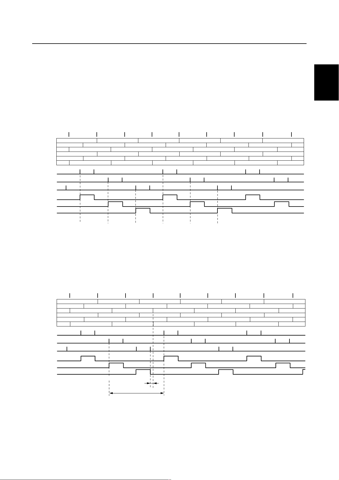
Over-revolution control
If the engine speed exceeds 4,500 r/min, while the shift is in neutral, ignition is stopped. The various
stages of ignition cutoff are shown in the table below.
Ignition cutoff cylinder in neutral
Set speed (r/min) #1 #2 #3 #4 #5 #6
4,500
4,750
: Indicates a misfire at either cylinder (once, due to simultaneously firing).
: Indicates a misfire at both cylinders (twice continuous).
If the engine speed exceeds 6,200 r/min, while the shift is in forward or reverse, the ignition is
stopped. The various stages of ignition cutoff are shown in the table below.
Ignition cutoff cylinder in forward or reverse
Set speed (r/min) #1 #2 #3 #4 #5 #6
6,200
General information
6,250
6,300
6,350
6,400
6,450
: Indicates a misfire at either cylinder (once, due to simultaneously firing).
: Indicates a misfire at both cylinders (twice continuous).
Dual-engine control
When two outboard engines are used, if one of the engines enters any one of the control modes, the
other engine will also control its ignition. This control is activated with the same engine speeds as
with other control modes.
Shift cutoff control
If the shift cut switch is activated with the engine operating under 2,000 r/min, the system causes
one or two cylinders to misfire in order to facilitate shifting. The system causes cylinders #1 and #2,
or #4 and #5 to misfire when the engine speed is over 850 r/min, and cylinder #1 or #4 to misfire
when the engine speed is under 850 r/min.
1-19
69J3D11

Fail-safe function table
Technical tips
Symptom
Incorrect pulser
coil signal
Incorrect engine
temperature sensor signal
Incorrect throttle
position sensor
signal
Incorrect intake air
temperature sensor signal
Incorrect neutral
switch signal
Incorrect intake air
pressure sensor
signal
Incorrect oil pressure sensor signal
Incorrect shift cut
switch signal
Incorrect thermoswitch signal
FAIL-SAFE FUNCTION
Ignition Injection ISC
Engine starting:
Only the cylinders
outputting normal
signal ignite at
BTDC10°, and all
cylinders thereafter.
Normal control
Ignition timing is
fixed to BTDC10°.
Normal control
Normal control Normal control Normal control Normal control
Normal control
Normal control Normal control
Normal control Normal control
Normal control Normal control
All cylinders inject
simultaneously
based on the cylinder that is outputting a normal signal.
Engine temperature
sensor is fixed to
40 °C to activate
normal control.
Correction is made
to the basic injection map.
Intake air temperature sensor is fixed
to 40 °C in order to
activate normal
control.
Correction is made
to the basic injection map.
Only in neutral:
900 r/min
Only in neutral:
900 r/min
Opening angle
is fixed to 60%.
Only in neutral:
900 r/min
Only in neutral:
900 r/min
Only in neutral:
900 r/min
In neutral:
900 r/min
In gear:
850 r/min
Only in neutral:
900 r/min
Engine
condition
Idle speed
increases
Idle speed
increases
Idle speed
increases
Idle speed
increases
Idle speed
increases
Idle speed
increases
Idle speed
increases
Idle speed
increases
DIAGNOSIS
CODE
13
15
18
23
28
29
39
45
46
1
2
3
4
5
6
69J3D11
7
8
9
1-20
GEN
INFO
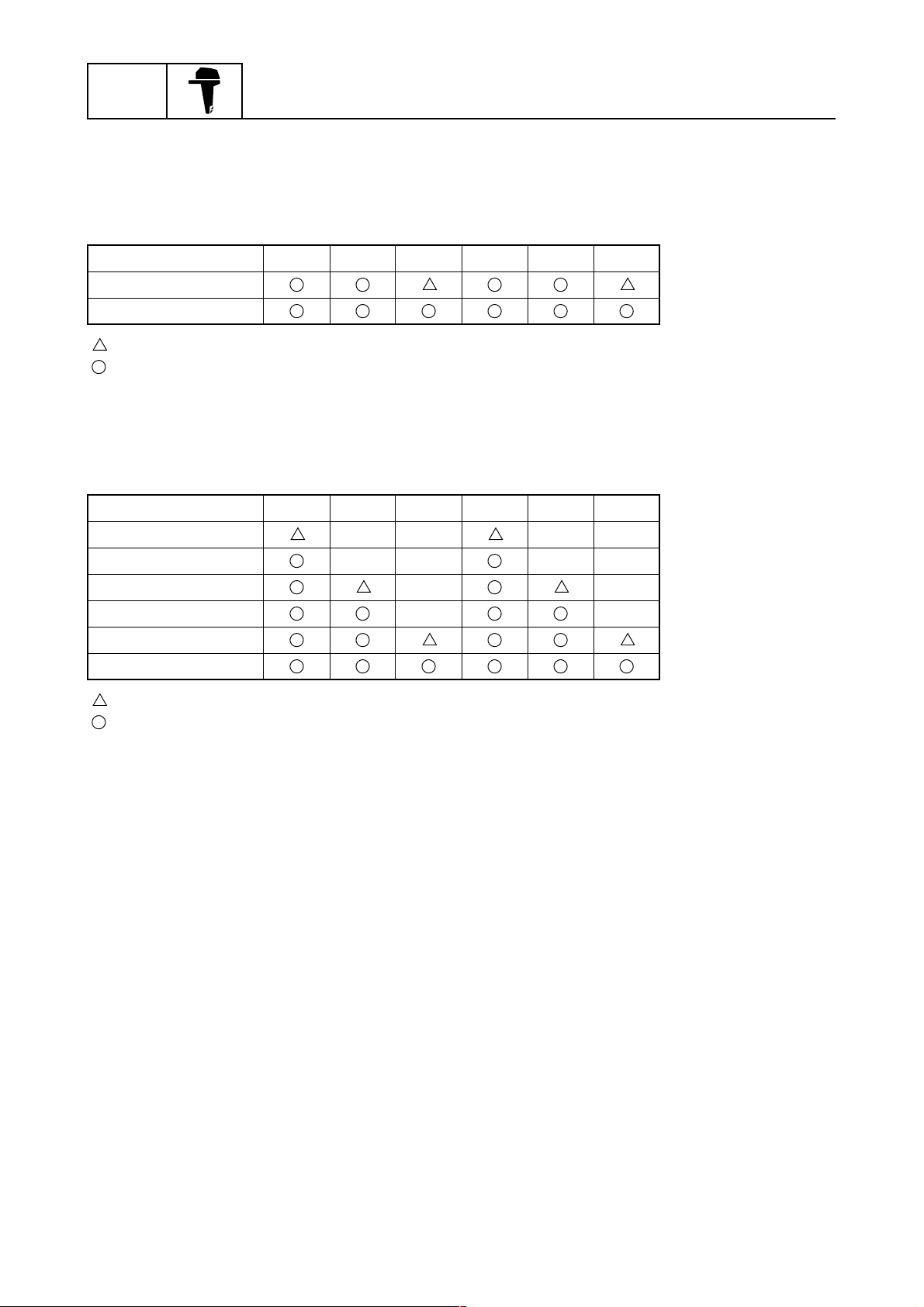
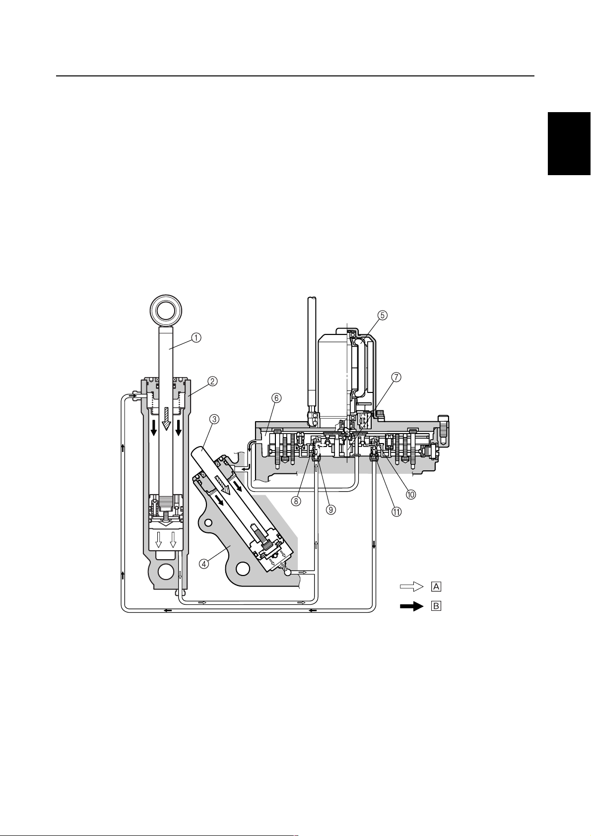
PTT (Power trim and tilt) unit
In the newly designed PTT unit, the up-main valve, down-main valve, up-relief valve, and downrelief valve have been concentrated in the gear pump housing in order to improve the serviceability
of the engine and ensure reliable operation.
General information
Tilt cylinder
1
Trim cylinder
2
Manual valve
3
Up-main valve
4
Down-main valve
5
Up-relief valve
6
Down-relief valve
7
Gear pump
8
Reservoir
9
Tilt ram
0
Tilt piston
A
Tilt piston absorber
B
Free piston
C
Shock return valve
D
Trim ram
E
Trim piston
F
Power trim and tilt motor
G
Up-shuttle piston
H
Down-shuttle piston
I
S69J1410
1-21
69J3D11
Technical tips
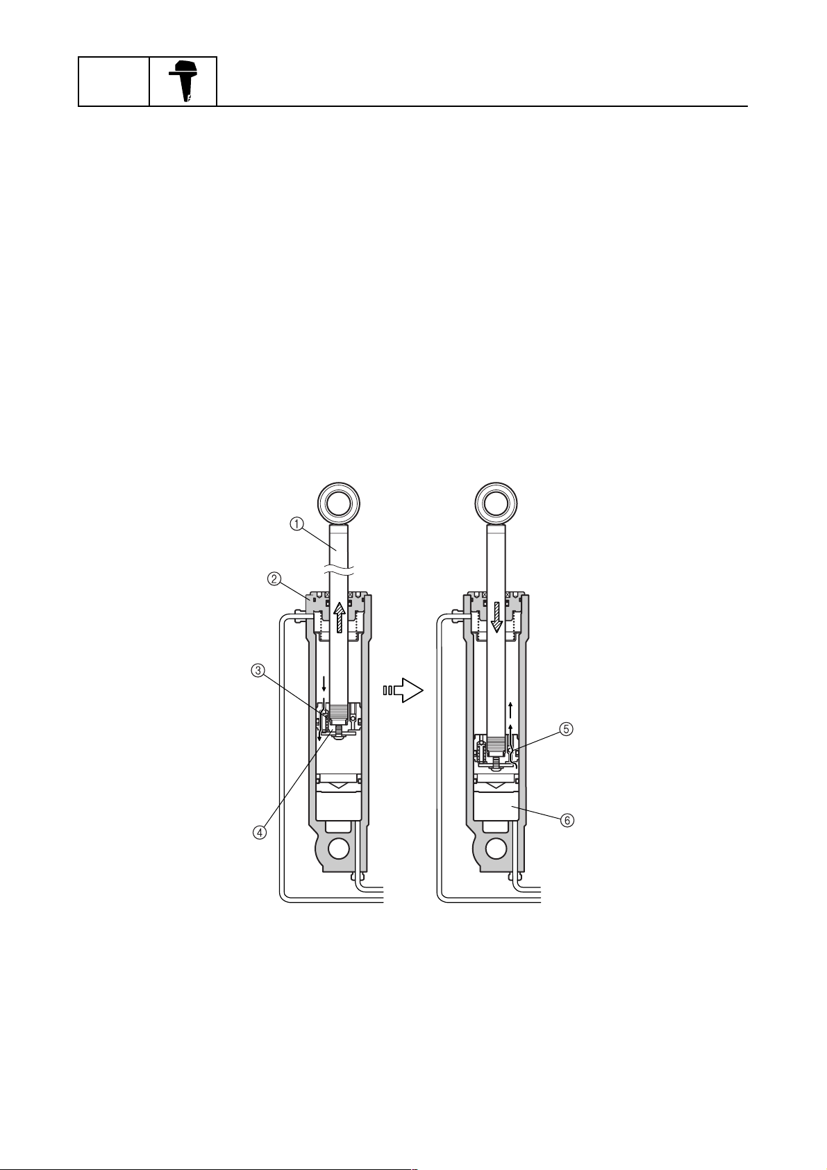
Trim-up and tilt-up function
When the PTT switch is pressed to “UP,” the power trim and tilt motor operates the gear pump and
fluid pressure is generated. As a result, the fluid pressure pushes the up-shuttle piston upward,
enters the trim cylinder and tilt cylinder lower chambers through the up-main valve, and then pushes
the tilt ram and trim ram upward.
In addition, the fluid pushes the down-shuttle piston downward, opens the down-main valve, and
returns the PTT fluid from the tilt cylinder upper chamber to the gear pump.
The fluid from the trim cylinder upper chamber then returns to the reservoir.
The tilt ram and the trim ram extend simultaneously, and after the trim ram has extended completely, the tilt ram operates to tilt up.
1
2
3
Tilt ram
1
Tilt cylinder
2
Trim ram
3
Trim cylinder
4
Power trim and tilt motor
5
Reservoir
6
Gear pump
7
Up-shuttle piston
8
Up-main valve
9
Down-shuttle piston
0
Down-main valve
A
Return
È
Send
É
4
5
6
:
:
S69J1420
7
8
69J3D11
9
1-22
GEN
INFO
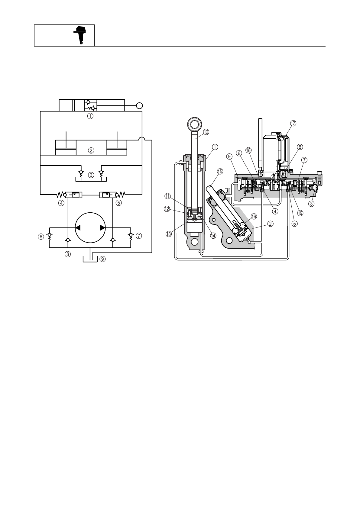
Trim ram retraction function
When the outboard motor is tilted up and held in place with the tilt stop lever and the PTT switch is
pressed to “DN,” the trim ram will be retracted.
Although the gear pump attempts to draw oil from the tilt cylinder and trim cylinder lower chambers,
after the PTT switch has been pressed, fluid cannot be drawn from the tilt cylinder lower chamber
because the tilt ram is secured in place by the tilt stop lever. Only the PTT fluid from the trim cylinder
lower chamber can be drawn, and as the fluid pressure decreases, the trim ram retracts into the trim
cylinder. Since the tilt ram is secured in place, the PTT fluid pumped by the gear pump flows into the
tilt cylinder upper chamber to increase fluid pressure. As a result, the down-relief valve opens, and
the PTT fluid is released into the reservoir.
General information
Tilt ram
1
Tilt cylinder
2
Trim ram
3
Trim cylinder
4
Gear pump
5
1-23
Reservoir
6
Down-relief valve
7
Return
È
Send
É
:
:
S69J1430
69J3D11
Technical tips
Trim-down and tilt-down function
When the PTT switch is pressed to “DN,” the power trim and tilt motor operates the gear pump and
fluid pressure is generated. As a result, the fluid pressure pushes the down-shuttle piston upward,
enters the tilt cylinder upper chamber through the down-main valve, and then pushes the tilt ram
downward.
In addition, the fluid pushes the up-shuttle piston downward to open the up-main valve.
The gear pump draws the PTT fluid from the tilt cylinder and trim cylinder lower chambers, and then
retracts the tilt ram and the trim ram.
Since the fluid pressure from the gear pump is applied to the tilt cylinder upper chamber, the tilt ram
moves downward first.
The hydraulic oil flows into the trim cylinder upper chamber from the reservoir.
When the outboard motor comes in contact with the trim ram, the trim ram moves downward simultaneously with the tilt ram, due to its own weight and the suction of the PTT fluid by the trim cylinder
lower chamber.
1
2
3
Tilt ram
1
Tilt cylinder
2
Trim ram
3
Trim cylinder
4
Power trim and tilt motor
5
Reservoir
6
Gear pump
7
Up-shuttle piston
8
Up-main valve
9
Down-shuttle piston
0
Down-main valve
A
Return
È
Send
É
4
5
6
7
:
:
S69J1440
8
9
69J3D11
1-24
GEN
INFO
Stationary condition
When the PTT switch is not pressed, the gear pump will not pump the fluid, the up-main valve and
the down-main valve will remain closed, and the PTT unit in the system remains constant. This will
allow the tilt ram and the trim ram to maintain their positions until the PTT fluid flows through the
system again.
When the outboard hits something in the water
If the lower casing comes in contact with an obstacle while the boat is in operation, a sudden extension force becomes applied to the tilt ram. This force causes the fluid pressure in the tilt cylinder
upper chamber to increase, and the tilt piston absorber to open and release the fluid pressure into
the space between the tilt piston and the free piston. As a result, the dampening effect of the tilt piston absorber and the oil lock mechanism prevent the PTT unit from damage, before the tilt piston
comes in contact with the top of the tilt cylinder.
After the collision, a force to return the outboard motor to its original position is generated due to the
weight of the outboard and the thrust of the propeller.
The PTT fluid passes through the shock return valve of the tilt piston, via the free piston, and into
the tilt cylinder upper chamber.
When the tilt piston comes in contact with the free piston, the tilt piston stops.
General information
Tilt ram
1
Tilt cylinder
2
Tilt piston absorber
3
1-25
Tilt piston
4
Shock return valve
5
Free piston
6
S69J1450
69J3D11

Cooling system
Technical tips
1
2
3
Cooling water inlet
1
Water pump
2
Oil pan
3
Exhaust pipe
4
PCV (Pressure control valve)
5
Lubrication system
Crankcase
Sleeve
Piston
Crankshaft pin
Crankshaft journal
Cylinder head
Intake and exhaust valves
Camshaft journal
In-bank exhaust system
6
Thermostat
7
Propeller boss
8
Water
È
Camshaft
:
S69J1460
4
5
Pressure feed
Splash
Return
6
7
69J3D11
Return route
• Oil pressure
regulation
Main gallery
Oil filter
Oil pump with relief valve
Oil strainer
Oil pan
• Oil sump
• Oil cooling
Oil pressure sensor
• Low oil pressure warning
• Filtration of foreign objects
• Suction/pressure feeding
of oil
• Prevention of air suction
• Filtration of large foreign objects
8
Return route
9
S69J1470
1-26

GEN
INFO
Propeller selection
The performance of a boat and outboard
motor will be critically affected by the size
and type of propeller you choose. Propellers
greatly affect boat speed, acceleration,
engine life, fuel economy, and even boating
and steering capabilities. An incorrect choice
could adversely affect performance and
could also seriously damage the engine.
Use the following information as a guide for
selecting a propeller that meets the operating
conditions of the boat and the outboard
motor.
Propeller size
The size of the propeller is indicated on the
propeller blade or outside of the propeller
boss.
General information
× -
Propeller diameter (in inches)
1
a
Propeller pitch (in inches)
b
Propeller type (propeller mark)
c
Selection
When the engine speed is at the full throttle
operating range (5,000–6,000 r/min), the
ideal propeller for the boat is one that provides maximum performance in relation to
boat speed and fuel consumption.
Regular rotation model
Propeller size (in) Material
13 3/4 × 17 - M
13 3/4 × 19 - M
13 3/4 × 21 - M
14 1/2 × 15 - M
14 1/2 × 19 - T
14 1/2 × 21 - T
14 7/8 × 21 - M
14 7/8 × 23 - M
15 × 17 - T
Stainless
× -
× -
S69J1100
S69J1110
15 1/4 × 15 - M
15 1/4 × 17 - M
15 1/4 × 19 - M
Counter rotation model
Propeller size (in) Material
13 3/4 × 17 - ML
13 3/4 × 19 - ML
13 3/4 × 21 - ML
14 1/2 × 15 - ML
14 1/2 × 19 - TL
14 1/2 × 21 - TL
Stainless
14 7/8 × 21 - ML
14 7/8 × 23 - ML
15 × 17 - TL
15 1/4 × 15 - ML
15 1/4 × 17 - ML
15 1/4 × 19 - ML
1-27
S69J1120
69J3D11

Propeller selection / Predelivery checks
Predelivery checks
To make the delivery process smooth and
efficient, the predelivery checks should be
completed as explained below.
Checking the fuel system
1. Check that the fuel hoses are securely
connected and that the fuel tank is full
with fuel.
1
Checking the engine oil
1. Check the oil level.
1
2
NOTE:
• If the engine oil is above the maximum level
mark (H), drain sufficient oil until the level is
between (H) and (L).
• If the engine oil is below the minimum level
mark (L), add sufficient oil until the level is
between (H) and (L).
3
4
S69J1130
CAUTION:
This is a 4-stroke engine. Never use premixed fuel.
Checking the gear oil
1. Check the gear oil level.
Recommended engine oil:
4-stroke motor oil
API: SE, SF, SG, or SH
SAE: 10W-30 or 10W-40
Oil capacity:
Without oil filter replacement:
5.8 L (6.1 US qt, 5.1 Imp qt)
Checking the battery
1. Check the capacity, electrolyte level, and
specified gravity of the battery.
Battery capacity: 12 V–100 Ah
2. Check that the red and black battery
cables are securely connected.
5
6
7
8
69J3D11
S69J1140
9
1-28

GEN
INFO
Checking the outboard motor
mounting height
1. Check that the anti-cavitation plate is
aligned with the bottom of the boat. If the
mounting height is too high, cavitation
will occur and propulsion will be reduced.
Also, the engine speed will increase
abnormally and cause the engine to
overheat. If the mounting height is too
low, water resistance will increase and
reduce engine efficiency.
General information
3. Check that the set pin c is in the center
of the shift bracket and aligned with the
alignment mark d on the bracket.
NOTE:
The optimum mounting height is affected by
the combination of the boat and the outboard
motor. To determine the optimum mounting
height, test run the outboard motor at different heights.
2. Check that the clamp brackets are
secured with the clamp bolts.
Checking the remote control cables
1. Set the remote control lever to the neutral position and fully close the throttle
lever.
2. Check that the throttle cam 1 is in its
fully close position and the alignment
mark a is between the alignment mark
b
.
S69J1190
CAUTION:
The shift/throttle cable joint must be
screwed in a minimum of 8.0 mm (0.31 in)
e
.
1-29
69J3D11

Predelivery checks
Checking the steering wheel
1. Check the steering friction for proper
adjustment.
2. Check that the steering operates
smoothly.
3. Check that there is no interference with
wires or hoses when the outboard motor
is steered.
Checking the gearshift and throttle
operation
1. Check that the gearshift operates
smoothly when the remote control lever
is shifted from neutral into forward or
reverse.
2. Check that the throttle operates smoothly
when the remote control lever is shifted
from the fully closed position to the fully
open position a.
Checking the tilt system
1. Check that the outboard motor tilts up
and down smoothly when operating the
power trim and tilt unit.
2. Check that there is no abnormal noise
produced when the outboard motor is
tilted up or down.
3. Check that there is no interference with
wires and hoses when the tilted-up outboard motor is steered.
4. Check that the trim meter points down
when the outboard motor is tilted all the
way down.
Checking the engine start switch and
engine stop switch/engine shut-off
switch
1. Check that the engine starts when the
engine start switch is turned to START.
2. Check that the engine turns off when the
engine start switch is turned to OFF.
3. Check that the engine turns off when the
engine stop switch is pushed or the
engine shut-off cord is pulled from the
engine shut-off switch.
1
2
3
4
5
6
69J3D11
N
F
R
7
S69J1220
8
S69J1210
9
1-30

GEN
INFO
Checking the cooling water pilot
hole
1. Check that cooling water is discharged
from the cooling water pilot hole.
General information
S69J1230
Test run
1. Start the engine, and then check that the
gearshift operates smoothly.
2. Check the engine idle speed after the
engine has been warmed up.
3. Operate at trolling speed.
4. Run the outboard motor for one hour at
2,000 r/min or at half throttle, then for
another hour at 3,000 r/min or at 3/4
throttle.
È
Hour
0
1
210
S69J1240
After test run
1. Check for water in the gear oil.
2. Check for fuel leakage in the cowling.
3. After a test run and while the engine is at
idle, flush the cooling water passage with
fresh water using the flushing kit.
5. Check that the outboard motor does not
tilt up when shifting into reverse and that
water does not flow in over the transom.
NOTE:
The test run is part of the break-in operation.
Break-in
During the test run, perform the break-in
operation in the following three stages.
1. One hour a at 2,000 r/min or at approximately half throttle.
2. One hour b at 3,000 r/min or 3/4 throttle
and one minute out of every ten at full
throttle.
3. Eight hours c at any speed, however,
avoid running at full speed for more than
five minutes.
1-31
69J3D11

SPEC
Specifications
General specifications...................................................................................2-1
Maintenance specifications ..........................................................................2-3
Power unit..................................................................................................2-3
Lower unit ..................................................................................................2-6
Electrical ....................................................................................................2-7
Dimensions................................................................................................2-9
Tightening torques.......................................................................................2-12
Specified torques.....................................................................................2-12
General torques.......................................................................................2-15
1
2
3
4
5
6
7
8
9
69J3D11

SPEC
Specifications
General specifications
Item Unit
F225AET FL225AET
Dimension
Overall length mm (in) 892 (35.1)
Overall width mm (in) 634 (25.0)
Overall height
(X) mm (in) 1,805 (71.1)
(U) mm (in) 1,932 (76.1)
Boat transom height
(X) mm (in) 635 (25.0)
(U) mm (in) 762 (30.0)
Weight
(with stainless propeller)
(X) kg (lb) 272 (600)
(U) kg (lb) 278 (613)
Performance
Maximum output kW (hp)
at 5,500 r/min
Full throttle operating range r/min 5,000–6,000
Maximum fuel consumption L (US gal,
lmp gal)/hr
at 6,000 r/min
Power unit
Type V6, 4-stroke, DOHC, 24 valves
Cylinder quantity 6
Displacement cm
3
(cu. in) 3,352 (204.5)
Bore × stroke mm (in) 94.0 × 80.5 (3.70 × 3.17)
Compression ratio 9.9
Control system Remote control
Starting system Electric
Ignition control system Microcomputer (TCI)
Ignition timing Degree TDC–BTDC 24
Alternator output V, A 12, 45
Spark plugs LFR5A-11 (NGK)
Cooling system Water
Exhaust system Through propeller boss
Lubrication system Wet sump
Model
165.5 (225.0)
70.0 (18.5, 15.4)
2
2-1
69J3D11

General specifications
Item Unit
Fuel and oil
Fuel type Regular unleaded gasoline
Fuel rating PON*
RON
Engine oil type 4-stroke motor oil
Engine oil grade API
SAE
Engine oil quantity
(with oil filter replacement)
(US qt, lmp qt)
(without oil filter replacement)
(US qt, lmp qt)
Gear oil type Hypoid gear oil
Gear oil grade API
Gear oil quantity
(US qt, lmp qt)
Bracket
Trim angle
(at 12 degree boat transom)
Tilt-up angle Degree 70
Steering angle Degree 32 + 32
Drive unit
Gearshift positions F-N-R
Gear ratio 2.00 (30/15)
Reduction gear type Spiral bevel gear
Clutch type Dog clutch
Propeller shaft type Spline
Propeller direction
(rear view)
Propeller identification mark T, M TL, ML
Electrical
Battery capacity V–Ah 12–100
L
L
SAE
L
Degree –3–16
F225AET FL225AET
SE, SF, SG, or SH
10W-30 or 10W-40
1.15 (1.22, 1.01) 1.00 (1.06, 0.88)
Clockwise Counterclockwise
Model
86
91
6.0 (6.3, 5.3)
5.8 (6.1, 5.1)
GL-4
90
1
2
3
4
5
6
7
* PON: Pump Octane Number (Research Octane Number + Motor Octane Number)/2
RON: Research Octane Number
69J3D11
8
9
2-2

SPEC
Specifications
Maintenance specifications
Power unit
Item Unit
F225AET FL225AET
Power unit
Minimum compression
pressure*
Lubrication oil pressure kPa (kgf/cm
kPa
(kgf/cm
2
, psi)
2
,
psi) at
700 r/min
Cylinder heads
Warpage limit mm (in) 0.1 (0.004)
(lines indicate straightedge
position)
Camshaft cap inside diameter mm (in) 25.00–25.02 (0.9843–0.9850)
Cylinders
Bore size mm (in) 94.00–94.02 (3.7008–3.7016)
Taper limit mm (in) 0.05 (0.0020)
Out-of-round limit mm (in) 0.01 (0.0004)
Pistons
Piston diameter (D) mm (in) 93.921–93.941 (3.6977–3.6985)
Measuring point (H) mm (in) 5 (0.2)
Piston-to-cylinder clearance mm (in) 0.075–0.080 (0.0029–0.0031)
Piston pin boss bore mm (in) 21.02–21.03 (0.8276–0.8280)
Piston pins
Outside diameter mm (in) 21.00 (0.827)
Piston rings
Top ring
Dimension B mm (in) 1.17–1.19 (0.0461–0.0468)
Dimension T mm (in) 2.8–3.0 (0.110–0.118)
End gap mm (in) 0.15–0.30 (0.0059–0.0118)
Side clearance mm (in) 0.04–0.08 (0.0016–0.0031)
2nd ring
Dimension B mm (in) 1.17–1.19 (0.0461–0.0468)
Dimension T mm (in) 3.6–3.8 (0.142–0.150)
End gap mm (in) 0.30–0.45 (0.0118–0.0177)
Side clearance mm (in) 0.03–0.07 (0.0012–0.0027)
Model
880 (8.8, 125)
650 (6.5, 924)
2
* Measuring conditions:
Ambient temperature 20 °C (68 °F), wide open throttle, with plugs disconnected from all cylinders.
The figures are for reference only.
2-3
69J3D11

Maintenance specifications
Item Unit
Oil ring
Dimension B mm (in) 2.40–2.47 (0.0945–0.0972)
Dimension T mm (in) 2.3–2.7 (0.091–0.106)
End gap mm (in) 0.15–0.60 (0.0059–0.0236)
Side clearance mm (in) 0.04–0.13 (0.0016–0.0051)
Camshafts
Intake (A) mm (in) 45.30–45.40 (1.7835–1.7874)
Exhaust (A) mm (in) 45.35–45.45 (1.7854–1.7894)
Intake and
exhaust (B)
Camshaft journal diameter mm (in) 24.96–24.98 (0.9827–0.9834)
Camshaft journal oil clearance mm (in) 0.02–0.06 (0.0008–0.0023)
Camshaft runout limit mm (in) 0.1 (0.004)
Valves
Valve clearance (cold)
Intake mm (in) 0.20 ± 0.03 (0.008 ± 0.001)
Exhaust mm (in) 0.34 ± 0.03 (0.013 ± 0.001)
Head diameter (A)
Intake mm (in) 34.85–35.15 (1.3720–1.3839)
Exhaust mm (in) 29.85–30.15 (1.1752–1.1870)
mm (in) 35.95–36.05 (1.4154–1.4193)
F225AET FL225AET
Model
1
2
3
4
Face width (B)
Intake mm (in) 2.11 (0.0831)
Exhaust mm (in) 2.43 (0.0957)
Seat contact width (C)
Intake mm (in) 1.1–1.4 (0.043–0.055)
Exhaust mm (in) 1.4–1.7 (0.055–0.067)
Margin thickness (D)
Intake mm (in) 0.7 (0.028)
Exhaust mm (in) 1.0 (0.039)
Stem diameter
Intake mm (in) 5.477–5.492 (0.2156–0.2162)
Exhaust mm (in) 5.464–5.479 (0.2151–0.2157)
Guide inside diameter
Intake and exhaust mm (in) 5.51–5.52 (0.2169–0.2173)
Stem-to-guide clearance
Intake mm (in) 0.01–0.02 (0.0004–0.0008)
Exhaust mm (in) 0.01–0.02 (0.0004–0.0008)
Stem runout limit mm (in) 0.01 (0.0004)
Valve springs
Free length mm (in) 44.20 (1.740)
Minimum free length mm (in) 42.60 (1.677)
Tilt limit mm (in) 1.5 (0.06)
5
6
7
8
9
69J3D11
2-4

SPEC
Specifications
Item Unit
Valve lifters
Valve lifter outside diameter mm (in) 32.98–33.00 (1.2984–1.2992)
Valve lifter-to-cylinder head
clearance
Valve shims
Valve shim thickness
(in 0.020 mm increments)
Connecting rods
Small-end inside diameter mm (in) 21.00 (0.827)
Big-end inside diameter mm (in) 53.00 (2.087)
Crankpin oil clearance mm (in) 0.035–0.071 (0.0014–0.0028)
Big-end bearing thickness
Yellow mm (in) 1.492–1.496 (0.0587–0.0588)
Green mm (in) 1.496–1.500 (0.0588–0.0591)
Blue mm (in) 1.500–1.504 (0.0591–0.0592)
Crankshaft
Crankshaft journal diameter mm (in) 62.968–62.992 (2.4791–2.4800)
Crankpin diameter mm (in) 49.976–50.000 (1.9676–1.9685)
Crankpin width mm (in) 21.50–21.55 (0.8465–0.8484)
Runout limit mm (in) 0.03 (0.0012)
Crankcase
Crankshaft main journal oil
clearance
Upper crankcase main journal
bearing thickness
1 mm (in) 2.494–2.500 (0.0981–0.0984)
2 mm (in) 2.498–2.504 (0.0983–0.0986)
3 mm (in) 2.502–2.508 (0.0985–0.0987)
Lower crankcase main journal
bearing thickness
1 mm (in) 2.494–2.500 (0.0981–0.0984)
2 mm (in) 2.498–2.504 (0.0983–0.0986)
3 mm (in) 2.502–2.508 (0.0985–0.0987)
#3 main journal bearing
thickness (lower)
1 mm (in) 2.492–2.500 (0.0980–0.0984)
2 mm (in) 2.496–2.504 (0.0982–0.0986)
3 mm (in) 2.500–2.508 (0.0984–0.0987)
mm (in) 0.02–0.05 (0.0008–0.0020)
mm (in) 2.320–2.960 (0.0913–0.1165)
mm (in) 0.025–0.050 (0.0010–0.0020)
F225AET FL225AET
Model
2-5
69J3D11

Maintenance specifications
Item Unit
Oil pump
Discharge
at 97–103 °C (207–217 °F)
with 10W-40 engine oil
Pressure kPa
Relief valve opening pressure kPa
Thermostats
Opening temperature °C (°F) 60 (140)
Fully open temperature °C (°F) 70 (158)
Valve open lower limit mm (in) 4.3 (0.17)
Engine speed
Engine idle speed r/min 650–750
Lower unit
Item Unit
Gear backlash
Pinion-to-forward gear mm (in) 0.21–0.44
Pinion-to-reverse gear mm (in) 0.70–1.03
Pinion shims mm 0.10, 0.12, 0.15, 0.18, 0.30, 0.40, 0.50
Forward gear shims mm 0.10, 0.12, 0.15, 0.18, 0.30, 0.40, 0.50
Reverse gear shims mm 0.10, 0.12, 0.15, 0.18, 0.30, 0.40, 0.50
Propeller shaft shims mm — 0.10, 0.12, 0.15, 0.18,
L (US gal,
Imp gal)/min
at 700 r/min
(kgf/cm
(kgf/cm
2
, psi)
2
, psi)
F225AET FL225AET
529–647 (5.29–6.47, 75.22–92.00)
F225AET FL225AET
(0.008–0.017)
(0.028–0.041)
Model
8.8 (2.32, 1.94)
138 (1.38, 19.62)
Model
0.35–0.70
(0.014–0.028)
0.70–1.03
(0.028–0.041)
0.30, 0.40, 0.50
1
2
3
4
5
6
69J3D11
7
8
9
2-6

SPEC
Electrical
Specifications
Item Unit
Ignition and ignition control
system
Ignition timing
(engine idle speed) Degree TDC
Pulser coil output peak voltage
(W/R – B, W/B – B, W/G – B)
at cranking (unloaded) V 5.3
at cranking (loaded) V 5.3
at 1,500 r/min (loaded) V 20
at 3,500 r/min (loaded) V 43
Pulser coil resistance
(W/R – B, W/B – B, W/G – B)
ECM output peak voltage
(B/O – B, B/Y – B, B/W – B)
at cranking (loaded) V 252
at 1,500 r/min (loaded) V 260
at 3,500 r/min (loaded) V 260
Spark plug gap mm (in) 11 (0.43)
Ignition coil resistance
Primary coil
(R/Y – B/O, R/Y – B/Y,
Secondary coil
(spark plug wire –
spark plug wire)
Throttle position sensor output
voltage (P – B)
Oil pressure sensor output
voltage (engine idle speed)
Intake air temperature sensor
resistance
at 0 °C (32 °F) kΩ 5.4–6.6
at 80 °C (176 °F) kΩ 0.29–0.39
Engine temperature sensor
resistance (B/Y – B)
at 20 °C (68 °F) kΩ 54.2–69.0
at 100 °C (212 °F) kΩ 3.12–3.48
(*1)
The figures are for reference only.
(*1)
R/Y – B/W)
(O – B)
Ω
459–561
Ω
1.5–1.9
kΩ 19.6–35.4
mV 695–705
V3.8
F225AET FL225AET
Model
2-7
69J3D11

Maintenance specifications
Item Unit
Starter motor
Type Sliding gear
Output kW 1.4
Cranking time limit Second 30
Brushes
Standard length mm (in) 15.5 (0.61)
Wear limit mm (in) 9.5 (0.37)
Commutator
Standard diameter mm (in) 29.0 (1.14)
Wear limit mm (in) 28.0 (1.10)
Mica
Standard undercut mm (in) 0.5–0.8 (0.02–0.03)
Wear limit mm (in) 0.2 (0.01)
Charging system
Fuse A 5, 20, 30
Stator coil output peak voltage
(G – G)
at cranking (unloaded) V 10
at 1,500 r/min (unloaded) V 42
at 3,500 r/min (unloaded) V 93
(G/W – G/W)
at cranking (unloaded) V 9.0
at 1,500 r/min (unloaded) V 34
at 3,500 r/min (unloaded) V 78
Stator coil resistance
Rectifier Regulator output
peak voltage (R – B, R/Y – B)
at 1,500 r/min (unloaded) V 13
at 3,500 r/min (unloaded) V 13
Power trim and tilt system
Trim sensor
Setting resistance
Resistance (P – B)
Fluid type ATF Dexron
Brushes
Standard length mm (in) 12.0 (0.47)
Wear limit mm (in) 4.0 (0.16)
Commutator
Standard diameter mm (in) 25.0 (0.98)
(*1)
The figures are for reference only.
(*1)
(G – G)
(G/W – G/W)
Ω
0.24–0.41
Ω
0.21–0.30
Ω
9–11
Ω
9–387.6
F225AET FL225AET
Model
1
2
3
4
5
6
7
8
II
9
69J3D11
2-8

SPEC
Dimensions
Exterior
Specifications
W5
T1
A1
W1
H9
H1
H2
H4
H3
H7
H8
H10
L7
L2 L1
L10
L8
C3
L5
L6
A2
H6
2-9
H11
12˚
A3
L9 L4
S69J2130
69J3D11

Maintenance specifications
Symbol Unit
L1 mm (in) 651 (25.6)
L2 mm (in) 219 (8.6)
L3 mm (in) —
L4 mm (in) 673 (26.5)
L5 (X) mm (in) 59 (2.3)
(U) mm (in) 59 (2.3)
L6 (X) mm (in) 1,155 (45.5)
(U) mm (in) 1,272 (50.1)
L7 mm (in) 618 (24.3)
L8 mm (in) 230 (9.1)
L9 (X) mm (in) 52 (2.0)
(U) mm (in) 59 (2.3)
L10 mm (in) 75 (3.0)
H1 (X) mm (in) 1,078 (42.4)
(U) mm (in) 1,205 (47.4)
H2 mm (in) 727 (28.6)
H3 mm (in) 216 (8.5)
H4 (X) mm (in) 643 (25.3)
(U) mm (in) 770 (30.3)
H5 mm (in) —
H6 (X) mm (in) 847 (33.3)
(U) mm (in) 924 (36.4)
H7 mm (in) 361 (14.2)
H8 mm (in) 39 (1.5)
H9 mm (in) 880 (34.6)
H10 mm (in) 45 (1.8)
H11 (X) mm (in) 25 (1.0)
(U) mm (in) 25 (1.0)
W1 mm (in) 317 (12.5)
W2 mm (in) —
W3 mm (in) —
W4 mm (in) —
W5 mm (in) 453 (17.8)
W6 mm (in) —
A1 Degree 32
A2 Degree 70
A3 Degree 3
T1 mm (in) 724 (28.5)
F225AET FL225AET
Model
1
2
3
4
5
6
7
8
69J3D11
9
2-10

SPEC
Clamp bracket
Specifications
B5
B3
B4
D1
B6
B1
D1
Symbol Unit
B9
B9
B9
B2
D2
C3
Model
F225AET FL225AET
B1 mm (in) 125 (4.9)
B2 mm (in) 254 (10.0)
B3 mm (in) 163 (6.4)
B4 mm (in) 51 (2.0)
B5 mm (in) 180 (7.1)
B6 mm (in) 411 (16.2)
B7 mm (in) —
B8 mm (in) —
B9 mm (in) 19 (0.7)
C2 mm (in) —
C3 mm (in) 79 (3.1)
D1 mm (in) 13 (0.5)
D2 mm (in) 56 (2.2)
S69J2140
2-11
69J3D11

Maintenance specifications / Tightening torques
Tightening torques
Specified torques
Part to be tightened Thread size
Fuel system
Fuel filter holder bolt M6 8 0.8 5.8
Fuel filter bracket bolt M6 8 0.8 5.8
Intake air temperature sensor — 40.42.9
Low-pressure fuel pump bracket bolt M5 5 0.5 3.6
Fuel cooler nut — 50.53.6
Float chamber bracket bolt M8 7 0.7 5.1
High-pressure fuel pump relay nut — 30.32.1
Vapor separator cover screw M4 2 0.2 1.4
Link rod nut — 40.42.9
Magnet control lever joint — 40.42.9
Throttle cam bolt — 80.85.8
Power unit
PTT motor lead bolt M6 4 0.4 2.9
Upper case cover bolt M6 8 0.8 5.8
Apron bolt M6 8 0.8 5.8
Power unit bolt M9 • M10 42 4.2 30
Flywheel magnet nut — 240 24 174
PTT relay nut — 40.42.9
Starter relay lead bolt M6 4 0.4 2.9
Battery cable nut — 90.96.5
Starter motor bolt M8 29 2.9 21
Rectifier Regulator
Link rod nut — 40.42.9
Oil pressure sensor — 18 1.8 13
Oil filter union bolt — 34 3.4 25
Oil filter — 18 1.8 13
Driven sprocket bolt M10 60 6.0 43
Timing belt tensioner bolt — 39 3.9 28
Drive sprocket bolt M5 7 0.7 5.1
Cylinder head cover plate screw M4 2 0.2 1.4
Cylinder head cover bolt
Camshaft cap bolt
Exhaust cover bolt
Exhaust outer cover bolt
Exhaust outer cover plug M18 55 5.5 40
1st
2nd 12 1.2 8.7
1st
2nd 8 0.8 5.8
1st
2nd 17 1.7 12
1st
2nd 12 1.2 8.7
1st
2nd 28 2.8 20
M6
M6
M7
M6
M8
Tightening torques
N·mkgf·mft·lb
60.64.3
80.85.8
80.85.8
60.64.3
14 1.4 10
2
1
2
3
4
5
6
7
8
9
69J3D11
2-12

SPEC
Specifications
Part to be tightened Thread size
Timing chain tensioner bolt M6 12 1.2 8.7
Spark plug — 25 2.5 18
1st
2nd 37 3.7 27
Cylinder head bolt
Engine hanger bolt M6 12 1.2 8.7
Cooling water cover bolt M6 12 1.2 8.7
Starboard cylinder head plug — 23 2.3 17
Cylinder block plug — 23 2.3 17
Engine temperature sensor — 15 1.5 11
Connecting rod cap
Baffle plate nut — 12 1.2 8.7
Crankcase cover bolt
Crankcase cover plate screw M4 2 0.2 1.4
Oil pump screw — 40.42.9
Crankcase stud bolt
Crankcase bolt
Lower unit (regular rotation model)
Trim tab bolt M10 43 4.3 31
Lower unit bolt M10 47 4.7 34
Propeller nut — 55 5.5 40
Propeller shaft housing grease nipple — 60.64.3
Propeller shaft housing bolt M8 30 3.0 22
Pinion nut — 142 14.2 103
Lower unit (counter rotation model)
Trim tab bolt M10 43 4.3 31
Lower unit bolt M10 47 4.7 34
Propeller nut — 55 5.5 40
Ring nut — 108 10.8 78
Propeller shaft housing bolt M8 30 3.0 22
Propeller shaft housing grease nipple — 60.64.3
Pinion nut — 142 14.2 103
Bracket unit
Shift rod detent bolt — 18 1.8 13
Flushing hose adapter screw M6 5 0.5 3.6
3rd 90°
1st
2nd 28 2.8 20
1st
2nd 48 4.8 35
3rd 90°
1st
2nd 28 2.8 20
1st
2nd 90°
1st
2nd 90°
1st
2nd 28 2.8 20
M10
M8
—
M8
M8
M10
M8
Tightening torques
N·mkgf·mft·lb
19 1.9 14
14 1.4 10
23 2.3 17
14 1.4 10
25 2.5 18
40 4.0 29
14 1.4 10
2-13
69J3D11

Tightening torques
Part to be tightened Thread size
Upper case mount nut — 72 7.2 52
Engine oil drain bolt M14 27 2.7 19
Apron stay — 80.85.8
Pressure control valve — 80.85.8
Upper exhaust guide bolt
Oil strainer bolt M6 10 1.0 7.2
Oil pan bolt M8 20 2.0 14
Exhaust manifold bolt M8 20 2.0 14
Muffler bolt M8 20 2.0 14
Baffle plate screw M6 4 0.4 2.9
Clamp bracket self-locking nut — 22 2.2 16
Friction plate screw M6 4 0.4 2.9
Trim stopper nut — 36 3.6 25
Power trim and tilt unit
Power trim and tilt unit bolt M10 42 4.2 30
Reservoir bolt M8 18 1.8 13
Reservoir cap M12 7 0.7 5.1
Manual valve — 20.21.4
Fluid pipe — 15 1.5 11
Trim cylinder end screw — 160 16 115
Trim piston bolt M8 38 3.8 27
Tilt ram — 55 5.5 40
Tilt cylinder end screw — 90 9.0 65
Tilt piston bolt M6 7 0.7 5.1
Gear housing bolt M5 7 0.7 5.1
Gear housing bracket bolt M5 7 0.7 5.1
M8 20 2.0 14
M10 42 4.2 30
Tightening torques
N·mkgf·mft·lb
1
2
3
4
5
6
69J3D11
7
8
9
2-14

SPEC
Specifications
General torques
This chart specifies tightening torques for
standard fasteners with a standard ISO
thread pitch. Tightening torque specifications
for special components or assemblies are
provided in applicable sections of this manual. To avoid warpage, tighten multi-fastener
assemblies in a crisscross fashion and progressive stages until the specified torque is
reached. Unless otherwise specified, torque
specifications require clean, dry threads.
Components should be at room temperature.
General torque
Nut (A) Bolt (B)
8 mm M5 5 0.5 3.6
10 mm M6 8 0.8 5.8
12 mm M8 18 1.8 13
14 mm M10 36 3.6 25
17 mm M12 43 4.3 31
specifications
N·mkgf·mft·lb
2-15
69J3D11

CHK
ADJ
Periodic checks and adjustments
Special service tools .....................................................................................3-1
Maintenance interval chart............................................................................3-2
Top cowling ....................................................................................................3-4
Checking the top cowling...........................................................................3-4
Fuel system ....................................................................................................3-4
Checking the fuel joint and fuel hoses (fuel joint-to-fuel injector) ..............3-4
Measuring the fuel pressure (high-pressure fuel line) ...............................3-5
Checking the fuel filter ...............................................................................3-5
Power unit.......................................................................................................3-5
Checking the engine oil .............................................................................3-5
Changing the engine oil using an oil changer............................................3-6
Changing the engine oil by draining it .......................................................3-6
Replacing the oil filter ................................................................................3-7
Checking the timing belt ............................................................................3-8
Replacing the timing belt ...........................................................................3-8
Checking the valve clearance....................................................................3-8
Checking the spark plugs ..........................................................................3-8
Checking the thermostat............................................................................3-9
Checking the cooling water passage.........................................................3-9
1
2
3
4
5
Control system...............................................................................................3-9
Checking the throttle link and throttle cable operation...............................3-9
Adjusting the throttle link and throttle cable operation (with a stop bolt) ....3-10
Adjusting the throttle link and throttle cable operation
(without a stop bolt) ...............................................................................3-11
Checking the gearshift operation.............................................................3-12
Checking the engine idle speed ..............................................................3-13
Checking the ignition timing.....................................................................3-15
Power trim and tilt unit ................................................................................3-15
Checking the power trim and tilt operation .............................................. 3-15
Checking the power trim and tilt fluid level ..............................................3-16
Lower unit.....................................................................................................3-16
Checking the gear oil level ......................................................................3-16
Changing the gear oil ..............................................................................3-17
Checking the lower unit (for air leakage).................................................3-18
Checking the propeller.............................................................................3-18
General..........................................................................................................3-18
Checking the anodes...............................................................................3-18
Checking the battery................................................................................3-19
Lubrication ...............................................................................................3-20
6
7
8
9
69J3D11

CHK
ADJ
Periodic checks and adjustments
Special service tools
Fuel pressure gauge
90890-06786
Digital tachometer
90890-06760
3
Timing light
90890-03141
Leakage tester
90890-06762
3-1
69J3D11

Special service tools / Maintenance interval chart
Maintenance interval chart
Use the following chart as a guideline for general maintenance.
Adjust the maintenance intervals according to the operating conditions of the outboard motor.
Initial Every
(2 years)
400 hours
Refer to
page
5-40
5-21
3-10,
3-11
3-10,
3-11
3-16
Item Remarks
10 hours
50 hours
(Break-in)
Top cowling
Top cowling fit Check (before each use) 3-4
Fuel system
Fuel joint and fuel hoses Check (before each use) 3-4
Fuel filter (disposable type) Check/replace —
Fuel filter (water separator) Check (before each use) 3-5
Fuel tank
Power unit
Engine oil Check (before each use) 3-5
Oil filter Change 3-7
Oil pump Check 5-55
Timing chain Check/replace (1,000 hours
Chain tensioner Check/replace 5-39
Timing belt
Valve clearance Check/adjust 5-15
Spark plugs Clean/adjust/replace 3-8
Thermostat Check 5-60
Pressure control valve Check —
Flywheel magnet nut Check —
Motor exterior Check (before each use) —
Oil leakage Check —
Cooling water passage
Control system
Throttle link Check/adjust 3-9,
Throttle cable Check/adjust 3-9,
Shift cable Check/adjust 3-12
Engine idle speed Adjust 3-13
Ignition timing Check 3-15
Power trim and tilt unit
Power trim and tilt unit Check 3-15,
(*1)
Clean —
Change 3-6
(*2)
Check/replace 3-8,
(*3)
Clean (after each use) 3-9
100 hours
(3 months)
or 5 years)
(1 year)
200 hours
(6 months)
3
1
2
3
4
5
6
7
8
9
69J3D11
3-2

CHK
ADJ
Item Remarks
Lower unit
Gear oil Change 3-17
Impeller/Woodruff key Check/replace (500 hours
Oil seals Check/replace —
Propeller Check (before each use) 3-18
General
Anodes/Trim tab Check/replace 3-18
Battery Check/charge 3-19
Wiring and connectors Adjust/reconnect —
Nuts and bolts
Lubrication points Lubricate 3-20
Periodic checks and adjustments
Initial Every
10 hours
50 hours
(Break-in)
(3 months)
100 hours
or 30 months)
(*4)
Tighten —
(6 months)
(1 year)
200 hours
(2 years)
400 hours
Refer to
page
6-10,
6-38
NOTE:
(*1) If equipped with a portable fuel tank.
(*2) Be sure to replace the timing belt every 1,000 hours of operation or every five years.
(*3) The engine should be flushed with fresh water after operating in salt, turbid, or muddy water.
(*4) Do not retighten the cylinder head and crankcase bolts.
3-3
69J3D11

Maintenance interval chart / Top cowling / Fuel system
Top cowling
Checking the top cowling
1. Check the fitting by pushing the cowling
with both hands. Adjust if necessary.
2. Loosen the bolts 1.
3. Move the hook 2 up or down slightly to
adjust its position.
3
1
2
Fuel system
Checking the fuel joint and fuel
hoses (fuel joint-to-fuel injector)
1. Remove the flywheel magnet cover and
intake silencer.
2. Check the low-pressure fuel hose connections and fuel joint for leaks. Replace
if necessary. Also, check the fuel filter 1,
low-pressure fuel pump 2, and check
valve 3 for leaks and deterioration.
Replace if necessary.
3
3
4
NOTE:
• To loosen the fitting, move the hook in
direction a.
• To tighten the fitting, move the hook in
direction b.
4. Tighten the bolts.
5. Check the fitting again and, if necessary,
repeat steps 2–4.
6. Check the top cowling hose for cracks or
damage. Replace if necessary.
3. Check the high-pressure fuel hose connections and fuel joint 4 for leaks.
Replace if necessary. Also, check the
vapor separator 5, fuel rail 6, fuel injector 7, pressure regulator 8, and fuel
cooler 9 for leaks and deterioration.
Replace if necessary.
5
6
7
8
9
69J3D11
3-4

CHK
ADJ
Measuring the fuel pressure (highpressure fuel line)
1. Remove the cap 1.
2. Install the fuel pressure gauge onto the
pressure check valve.
É
Periodic checks and adjustments
NOTE:
Be sure not to spill any fuel when removing
the fuel filter cup.
Fuel pressure gauge: 90890-06786
3. Turn the engine start switch to ON, and
then measure the fuel pressure.
NOTE:
After the engine start switch is turned to ON,
the fuel pressure will decrease gradually.
Fuel pressure:
310 kPa (3.1 kgf/cm
2
, 44 psi)
4. Start the engine and warm it up for 5 minutes, and then measure the fuel pressure.
NOTE:
The pressure regulator can be checked since
2
the fuel pressure (310 kPa [3.1 kg/cm
, 44
psi]), from when the engine switch is turned
to ON, decreases when the engine is idling.
Fuel pressure:
270 kPa (2.7 kgf/cm
2
, 38 psi)
Checking the fuel filter
1. Check the fuel filter element 1 for dirt
and residue and check the fuel filter cup
2
for foreign substances and cracks.
Clean with straight gasoline and replace
the cup if necessary.
Power unit
Checking the engine oil
1. Place the outboard motor in an upright
position.
2. Remove the engine oil dipstick, wipe it
clean, and then insert it back into the oil
filler hole.
3. Remove the dipstick again to check the
oil level, and the oil for discoloration and
its viscosity.
NOTE:
• Change the oil if it appears milky or dirty.
• If the engine oil is above the maximum level
mark (H), drain sufficient oil until the level is
between (H) and (L).
• If the engine oil is below the minimum level
mark (L), add sufficient oil until the level is
between (H) and (L).
3
3-5
69J3D11

Fuel system / Power unit
Changing the engine oil using an oil
changer
1. Start the engine and warm it up.
2. Remove the engine oil dipstick and oil
filler cap 1.
3. Insert the tube of the oil changer 2 into
the dipstick guide 3.
6. Install the oil filler cap and dipstick, and
then start the engine and warm it up for 5
minutes.
7. Turn the engine off, and then check the
oil level and correct it if necessary.
Changing the engine oil by draining
it
1. Start the engine and warm it up.
2. Remove the engine oil dipstick and oil
filler cap 1.
1
2
3
4
4. Operate the oil changer to extract the oil.
NOTE:
Be sure to clean up any oil spills.
5. Pour the specified amount of the recommended engine oil into the oil filler hole.
Recommended engine oil:
4-stroke motor oil
API: SE, SF, SG, or SH
SAE: 10W-30 or 10W-40
Oil quantity:
Without oil filter replacement:
5.8 L (6.1 US qt, 5.1 Imp qt)
3. Remove the starboard apron 2.
5
6
S69J3120
7
4. Place a drain pan under the drain hole,
and then remove the drain bolt 3 and let
the oil drain completely.
8
9
69J3D11
3-6

CHK
T
R
.
.
ADJ
Periodic checks and adjustments
LT
572LT572
S69J3140
Apron bolt:
8 N·m (0.8 kgf·m, 5.8 ft·lb)
NOTE:
Be sure to clean up any oil spills.
5. Install the drain bolt, and then tighten it to
the specified torque.
Drain bolt:
T
.
R
.
27 N·m (2.7 kgf·m, 19 ft·lb)
6. Pour the specified amount of the recommended engine oil into the oil filler hole.
Recommended engine oil:
4-stroke motor oil
API: SE, SF, SG, or SH
SAE: 10W-30 or 10W-40
Oil quantity:
Without oil filter replacement:
5.8 L (6.1 US qt, 5.1 Imp qt)
Replacing the oil filter
1. Extract the engine oil with an oil changer
or drain it.
2. Remove the oil filter cover 1.
3. Place a rag under the oil filter, and then
remove the filter using a 72.5 mm (2.9 in)
oil filter wrench.
7. Install the oil filler cap and dipstick, and
then start the engine and warm it up for 5
minutes.
8. Turn the engine off, and then check the
oil level and correct it if necessary.
9. Install the starboard apron 2, and then
tighten it to the specified torque.
NOTE:
Be sure to clean up any oil spills.
4. Apply a thin coat of engine oil to the Oring of the new oil filter.
3-7
69J3D11

Power unit
5. Install the oil filter, and then tighten it to
the specified torque using a 72.5 mm
(2.9 in) oil filter wrench.
T
Oil filter: 18 N·m (1.8 kgf·m, 13 ft·lb)
.
R
.
3. Turn the crankshaft clockwise two turns
to take up slack in the timing belt.
Replacing the timing belt
NOTE:
For replacement procedures, see Chapter 5,
“Replacing the timing belt.”
Checking the valve clearance
1
2
3
4
6. Pour the specified amount of the recommended engine oil into the oil filler hole.
Recommended engine oil:
4-stroke motor oil
API: SE, SF, SG, or SH
SAE: 10W-30 or 10W-40
Oil quantity:
With oil filter replacement:
6.0 L (6.3 US qt, 5.3 Imp qt)
7. Install the oil filler cap and dipstick, and
then start the engine and warm it up for 5
minutes.
8. Turn the engine off, and then check the
oil level and correct it if necessary.
9. Install the oil filter cover.
Checking the timing belt
1. Remove the flywheel magnet cover.
NOTE:
For checking procedures, see Chapter 5,
“Checking the valve clearance.”
Checking the spark plugs
1. Remove the ignition coil cover.
2. Disconnect the spark plug wires, and
then remove the spark plugs.
3. Clean the electrodes 1 with a spark plug
cleaner or wire brush. Replace the spark
plug if necessary.
5
6
7
8
2. While turning the flywheel magnet clockwise, check the interior a and the exterior b of the timing belt for cracks,
damage, or wear. Replace if necessary.
69J3D11
9
4. Check the electrodes for erosion and
excessive carbon or other deposits, and
the gasket for damage. Replace the
spark plug if necessary.
3-8

CHK
ADJ
5. Check the spark plug gap a. Adjust if out
of specification.
Specified spark plug:
LFR5A-11 (NGK)
Spark plug gap a: 1.1 mm (0.043 in)
Periodic checks and adjustments
6. Install the spark plug, tighten it finger
tight b, then to the specified torque with
a spark plug wrench c.
Spark plug:
T
.
R
.
25 N·m (2.5 kgf·m, 18 ft·lb)
Checking the thermostat
NOTE:
For checking procedures, see Chapter 5,
“Checking the thermostat.”
Checking the cooling water passage
1. Check the cooling water inlet cover
and cooling water inlet for clogs. Clean if
necessary.
1
S69J3220
2. Place the lower unit in water, and then
start the engine.
3. Check for water flow at the cooling water
pilot hole. If there is no water flow, check
the cooling water passage inside the outboard motor.
S69J3225
Control system
Checking the throttle link and throttle
cable operation
1. Check that the throttle control cam 1 is
in its fully closed position and the alignment mark a is between the alignment
mark b when the remote control lever is
in the neutral position. Adjust the length
of the throttle cable and position of the
throttle control lever if necessary.
3
3-9
69J3D11

Adjusting the throttle link and
throttle cable operation (with a stop
bolt)
NOTE:
• Be sure to synchronize the throttle valves
before adjusting the throttle link.
• For synchronizing procedures, see Chapter
4, “Synchronizing the throttle valve.”
1. Loosen the locknut 1, remove the clip
2
, and then disconnect the throttle cable
joint 3.
Power unit / Control system
4. Push the throttle control lever 8 against
the stop bolt 7.
NOTE:
Use a general bolt with the specified measurements.
Stop bolt 7:
a
: 10 mm (0.39 in)
b
: 6.0 mm (0.24 in)
c
: 1.0 mm (0.04 in)
5. Push the magnet control lever 6 in the
direction of the arrow to eliminate any
looseness, and then adjust the link rod
so that it aligns with the magnet control
lever joint 9.
5
1
2
3
4
5
2. Loosen the locknut 4 and disconnect the
link rod 5 from the magnet control lever
6
.
3. Install the stop bolt (general bolt) 7 into
the threaded hole.
6. Install the link rod 5 and tighten the locknut 4.
7. Remove the stop bolt 7.
8. Check that the alignment mark d is
between the alignment mark e. If not,
repeat steps 2–6.
6
7
8
9
69J3D11
3-10

CHK
ADJ
9. Place the throttle cam 0 against the fully
closed stopper f, and check that there
is a minimum clearance g of approximately 1.0 mm (0.04 in).
Periodic checks and adjustments
12. Check the throttle cable for smooth operation and adjust the cable length, if necessary, repeating steps 1–10.
Adjusting the throttle link and
throttle cable operation (without a
stop bolt)
NOTE:
• Be sure to synchronize the throttle valves
before adjusting the throttle link.
• For synchronizing procedures, see Chapter
4, “Synchronizing the throttle valve.”
1. Loosen the locknut 1, remove the clip
2
, and then disconnect the throttle cable
joint 3.
10. Adjust the position of the throttle cable
joint until its hole is aligned with the set
pin h on the throttle cam.
S69J3300
CAUTION:
The throttle cable joint must be screwed
in a minimum of 8.0 mm (0.31 in) i.
11. Connect the cable joint, install the clip,
and then tighten the locknut.
2. Loosen the locknut 4 and disconnect the
link rod 5 from the magnet control lever
6
.
3. Adjust the link rod 5 so that the alignment mark a is between the alignment
marks b. Then, push the magnet control
lever 6 in the direction of the arrow to
eliminate any looseness.
4. Install the link rod 5 and tighten the locknut 4.
3-11
69J3D11

5. Check that the alignment mark a is
between the alignment marks b. If not,
repeat steps 2–4.
Control system
S69J3340
CAUTION:
The throttle cable joint must be screwed
in a minimum of 8.0 mm (0.31 in) f.
8. Connect the cable joint, install the clip,
and then tighten the locknut.
9. Check the throttle cable for smooth operation and adjust the cable length, if necessary, repeating steps 1–7.
1
2
3
4
6. Place the throttle cam 7 against the fully
closed stopper c, and check that there
is a minimum clearance d of approximately 1.0 mm (0.04 in).
7. Adjust the position of the throttle cable
joint until its hole is aligned with the set
pin e on the throttle cam.
Checking the gearshift operation
1. Check that the gearshift operates
smoothly when shifting from neutral into
forward or reverse. Adjust the shift cable
length if necessary.
2. Set the gearshift to the neutral position.
3. Loosen the locknut 1, remove the clip
2
, and then disconnect the shift cable
joint 3.
4. Align the set pin a in the center of the
shift bracket and with the alignment
marks b on the bracket.
5
6
7
8
9
69J3D11
3-12

CHK
ADJ
Periodic checks and adjustments
5. Adjust the position of the shift cable joint
until its hole is aligned with the set pin.
S69J3370
CAUTION:
The shift cable joint must be screwed in a
minimum of 8.0 mm (0.31 in) c.
6. Connect the cable joint, install the clip,
and then tighten the locknut.
7. Check the gearshift for smooth operation
and adjust the shift cable length, if necessary, repeating steps 3–6.
Digital tachometer: 90890-06760
Engine idle speed: 650–750 r/min
4. Turn the engine off, loosen the locknut
2
, and then disconnect the link rod
from the magnet control lever 4.
5. Loosen the port throttle stop screw
until it separates from the throttle body
lever 6.
3
5
Checking the engine idle speed
1. Remove the ignition coil cover.
2. Start the engine and warm it up for 5 minutes.
3. Attach the special service tool to spark
plug wire #1 1, and then check the
engine idle speed. Adjust if out of specification.
3-13
6. Start the engine, and then turn the starboard throttle stop screw 7 in direction
a
or b until the specified engine idle
speed is obtained.
69J3D11

Control system
10. Install the link rod 3, and then tighten
the locknut 2.
11. Check that the alignment mark c is
between the alignment marks d. If necessary, repeat steps 8–10.
1
NOTE:
• To increase the idle speed, turn the throttle
stop screw in direction a.
• To decrease the idle speed, turn the throttle
stop screw in direction b.
7. Tighten the port throttle stop screw
until it contacts the throttle body lever 6.
8. Loosen the locknut 8, remove the clip
9
, and then disconnect the throttle cable
joint 0.
5
12. Place the throttle cam A against the fully
closed stopper e, and check that there
is a minimum clearance f of approximately 1.0 mm (0.04 in).
2
3
4
5
6
9. Adjust the link rod 3 so that the alignment mark c is between the alignment
marks d. Then, push the magnet control
lever 4 in the direction of the arrow to
eliminate any looseness.
69J3D11
7
8
9
13. Adjust the position of the throttle cable
joint until its hole is aligned with the set
pin g on the throttle cam.
3-14

CHK
ADJ
CAUTION:
The throttle cable joint must be screwed
in a minimum of 8.0 mm (0.31 in) h.
14. Connect the cable joint, install the clip,
and then tighten the locknut.
Periodic checks and adjustments
S69J3470
4. Attach the special service tool to spark
plug wire #1.
15. Check the throttle cable for smooth operation and adjust the cable length, if necessary, repeating steps 8–12.
Checking the ignition timing
1. Remove the ignition coil cover.
2. Start the engine and warm it up for 5 minutes.
3. Attach the special service tool to spark
plug wire #1 1, and then check the
engine idle speed. Adjust if out of specification.
Timing light: 90890-03141
5. Check that the “1TDC” mark a on the
flywheel magnet is aligned with the magnet base pointer b.
Ignition timing: TDC
3-15
Digital tachometer: 90890-06760
Engine idle speed: 650–750 r/min
Power trim and tilt unit
Checking the power trim and tilt
operation
1. Fully tilt the outboard motor up and down
a few times and check the entire trim and
tilt range for smooth operation. Check the
power trim and tilt fluid level if necessary.
69J3D11
3

T
R
.
.
Control system / Power trim and tilt unit / Lower unit
NOTE:
Be sure to listen to the winding sound of the
power trim and tilt motor for smooth operation.
2. Fully tilt the outboard motor up, and then
support it with the tilt stop lever 1 to
check the lock mechanism of the lever.
1
Checking the power trim and tilt fluid
level
1. Fully tilt the outboard motor up, and then
support it with the tilt stop lever 1.
NOTE:
If the fluid is at the correct level, the fluid
should overflow out of the filler hole when the
cap is removed.
3. If necessary, add sufficient fluid of the
recommended type until it overflows out
of the filler hole.
Recommended power trim and tilt
fluid:
ATF Dexron II
4. Install the reservoir cap, and then tighten
it to the specified torque.
Reservoir cap:
7 N·m (0.7 kgf·m, 5.1 ft·lb)
Lower unit
Checking the gear oil level
1. Fully tilt the outboard motor down.
2
3
4
5
6
3
WARNING
After tilting up the outboard motor, be
sure to support it with the tilt stop lever.
Otherwise, the outboard motor could suddenly lower if the power trim and tilt unit
should lose fluid pressure.
2. Remove the reservoir cap 2, and then
check the fluid level in the reservoir.
69J3D11
2. Remove the check screw 1, and then
check the gear oil level in the lower case.
S69J3520
3-16
7
8
9

CHK
ADJ
NOTE:
If the oil is at the correct level, the oil should
overflow out of the check hole when the
check screw is removed.
3. If necessary, add sufficient gear oil of the
recommended type until it overflows out
of the check hole.
Recommended gear oil:
Hypoid gear oil
SAE: 90
4. Install the check screw.
Changing the gear oil
1. Tilt the outboard motor up slightly.
Periodic checks and adjustments
S69J3540
2. Place a drain pan under the drain screw
1
, remove the drain screw, then the
check screw 2 to drain the oil.
3. Check the oil for metal, discoloration, and
its viscosity. Check the internal parts of
the lower case if necessary.
S69J3550
Recommended gear oil:
Hypoid gear oil
SAE: 90
Oil quantity:
Regular rotation model:
1.15 L (1.22 US qt, 1.01 Imp qt)
Counter rotation model:
1.00 L (1.06 US qt, 0.88 Imp qt)
5. Install the check screw and quickly install
the drain screw.
4. Insert the gear oil tube or gear oil pump
into the drain hole and slowly fill the gear
oil until oil flows out of the check hole and
no air bubbles are visible.
3-17
69J3D11

Lower unit / General
Checking the lower unit
(for air leakage)
1. Remove the check screw 1, and then
install the special service tool.
É
Leakage tester: 90890-06762
2. Apply the specified pressure to check
whether the lower unit can hold it for at
least 10 seconds.
Checking the propeller
1. Check the propeller blades and splines
for cracks, damage, or wear. Replace if
necessary.
S69J3580
General
Checking the anodes
1. Check the anodes and trim tab for
scales, grease, or oil. Clean if necessary.
1
2
3
3
4
CAUTION:
Do not over pressurize the lower unit, otherwise the oil seals may be damaged.
NOTE:
Cover the check hole with a rag when removing the pressure/vacuum tester from the
lower unit.
Lower unit holding pressure:
2
100 kPa (1.0 kgf/cm
3. If pressure drops below specification,
check the drive shaft and propeller shaft
oil seals for damage.
, 14 psi)
5
6
7
8
69J3D11
9
3-18

CHK
ADJ
CAUTION:
Do not oil, grease, or paint the anodes,
otherwise they will be ineffective.
2. Replace the anodes and trim tab if
excessively eroded.
Checking the battery
1. Check the battery electrolyte level. If the
level is at or below the minimum level
mark a, add distilled water until the level
is between the maximum and minimum
level marks.
Periodic checks and adjustments
WARNING
Battery electrolyte is dangerous; it contains sulfuric acid which is poisonous and
highly caustic.
Always follow these preventive measures:
• Avoid bodily contact with electrolyte as
it can cause severe burns or permanent
eye injury.
• Wear protective eye gear when handling
or working near batteries.
Antidote (EXTERNAL):
• SKIN – Wash with water.
• EYES – Flush with water for 15 minutes
and get immediate medical attention.
Antidote (INTERNAL):
• Drink large quantities of water or milk
followed with milk of magnesia, beaten
egg, or vegetable oil. Get immediate
medical attention.
Batteries generate explosive, hydrogen
gas. Always follow these preventive measures:
• Charge batteries in a well-ventilated
area.
• Keep batteries away from fire, sparks or
open flames (e.g., welding equipment,
lighted cigarettes).
• DO NOT SMOKE when charging or handling batteries.
KEEP BATTERIES AND ELECTROLYTE
OUT OF REACH OF CHILDREN.
S69J3620
2. Check the specific gravity of the electrolyte. Fully charge the battery if out of
specification.
3-19
NOTE:
• Batteries vary per manufacturer. The procedures mentioned in this manual may not
always apply, therefore, consult the instruction manual of the battery.
• Disconnect the black battery cable first,
then the red battery cable.
Electrolyte specific gravity:
1.280 at 20 °C (68 °F)
69J3D11

Lubrication
1. Apply water resistant grease to the areas
shown.
General
1
2
3
4
5
6
7
8
69J3D11
9
3-20

CHK
ADJ
NOTE:
Apply grease to the grease nipple until it
flows from the bushings a.
2. Apply corrosion resistant grease to the
areas shown.
Periodic checks and adjustments
3-21
69J3D11

FUEL
Fuel system
Special service tools .....................................................................................4-1
Hose routing...................................................................................................4-2
Fuel and blowby hoses..............................................................................4-2
Intake silencer, fuel filter, and fuel pump ....................................................4-3
Vapor separator..............................................................................................4-5
Removing the hose clamps .......................................................................4-7
Installing the hose clamps .........................................................................4-7
Checking the check valve..........................................................................4-7
Reducing the fuel pressure........................................................................4-7
Checking the vapor separator ...................................................................4-8
Intake manifold and high-pressure fuel line................................................ 4-9
Throttle control.............................................................................................4-13
Removing the pressure regulator ............................................................4-15
Disconnecting the high-pressure fuel hose joint...................................... 4-15
Checking the fuel injector ........................................................................4-15
Checking the idle speed control (ISC).....................................................4-15
Synchronizing the throttle valve...............................................................4-16
1
2
3
4
5
6
7
8
9
69J3D11

FUEL
Fuel system
Special service tools
Vacuum/pressure pump gauge set
90890-06756
Digital circuit tester
90890-03174
4
Test harness (3 pins)
90890-06793
Vacuum gauge
90890-03159
4-1
69J3D11

Special service tools / Hose routing
Hose routing
Fuel and blowby hoses
4
1
2
3
4
Blowby hose
1
Fuel hose (fuel joint-to-fuel filter)
2
Fuel hose (fuel filter-to-fuel pump)
3
Fuel hose (fuel pump-to-vapor separator)
4
Fuel hose (vapor separator-to-fuel pump)
5
High-pressure fuel hose
6
(vapor separator-to-starboard fuel rail)
High-pressure fuel hose
7
(starboard fuel rail-to-port fuel rail)
Fuel hose (pressure regulator-to-fuel cooler)
8
Fuel hose (fuel cooler-to-vapor separator)
9
5
6
7
8
9
69J3D11
4-2

FUEL
Fuel system
Intake silencer, fuel filter, and fuel pump
4
4-3
69J3D11

Intake silencer, fuel filter, and fuel pump
No. Part name Q’ty Remarks
1 Cover 1
2Bolt 3 M6 × 28 mm
3Bolt 1 M6 × 16 mm
4 Washer 1
5 Holder 1
6Bolt 1 M6 × 14 mm
7Bracket 1
8Bolt 2 M6 × 19 mm
9Cap 1
10 Fuel hose 8
11 Fuel joint 1
12 O-ring 1
13 Fuel filter element 1
14 Spring 1
15 O-ring 1
16 Cup 1
Not reusable
Not reusable
1
2
3
4
17 Nut 1
18 Bolt 1 M6 × 16 mm
19 Bolt 1 M7 × 20 mm
20 Battery cable 1
21 Starboard intake silencer 1
22 Port intake silencer 1
23 Intake air temperature sensor 1
24 Check valve 2
25 Hose 2
26 Joint 1
27 Joint 2
28 Nut 4
29 Grommet 6
30 Screw 1 M5 × 7 mm
31 Cover 1
32 Fuel filter 1
33 Clamp 2
34 Bolt 2 M5 × 12 mm
5
6
7
8
35 Bracket 1
36 Low-pressure fuel pump 1
37 Bolt 4 M6 × 45 mm
38 Clamp 10
69J3D11
9
4-4

FUEL
Fuel system
Vapor separator
4
4-5
69J3D11

Vapor separator
No. Part name Q’ty Remarks
1 Float chamber 1
2 Cover 1
3 High-pressure fuel pump 1
4Float 1
5 Water hose 1
6 Fuel hose 3
7 Joint 1
8 Fuel cooler 1
9 Washer 2
10 Nut 2
11 Water hose 1
12 Bracket 1
13 Bolt 3 M8 × 16 mm
14 Collar 6
15 Bushing 4
16 Bolt 4 M8 × 16 mm
1
2
3
4
17 Collar 1
18 High-pressure fuel pump relay 1
19 Washer 2
20 Nut 1
21 Hose 3
22 Screw 7 M4 × 15 mm
23 Bracket 1
24 Bolt 1 M6 × 10 mm
25 Gasket 1
26 Plate 2
27 Grommet 1
28 Screw 3 M4 × 8 mm
29 Plate 1
30 Needle valve 1
31 Pin 1
32 Bracket 1
33 Screw 1
34 Gasket 1
Not reusable
5
6
7
8
35 Drain screw 1
36 Joint 1
37 Filter 1
38 Filter holder 1
69J3D11
9
4-6

FUEL
Fuel system
Removing the hose clamps
1. Remove the hose clamps by cutting the
joint.
CAUTION:
If the hose clamps are removed without
cutting the joint first, the fuel hose will be
damaged.
Installing the hose clamps
1. Crimp the hose clamps properly to
securely fasten them.
WARNING
Do not reuse the hose clamps, always
replace them with new ones.
Checking the check valve
1. Install the special service tool onto the
check valve.
Vacuum/pressure pump gauge set:
90890-06756
2. Apply the pressure to each check valve
port. Replace if necessary.
NOTE:
Make sure no air comes out of the opposite
side of the check valve.
Reducing the fuel pressure
1. Remove the cap 1.
2. Cover the pressure check valve a of the
vapor separator with a rag, and then
press in the valve using a thin screwdriver 2 to release the fuel pressure.
4-7
69J3D11

WARNING
Always reduce the fuel pressure in the
high-pressure fuel line before servicing
the line or the vapor separator. If the fuel
pressure is not released, pressurized fuel
may spray out.
Vapor separator
WARNING
Reduce the fuel pressure before removing
the vapor separator drain screw, or pressurized fuel will spray out and may result
in serious injury.
Checking the vapor separator
1. Check the needle valve for bends or
wear. Replace if necessary.
2. Check the float for deterioration. Replace
if necessary.
1
2
3
4
5
3. Remove the cap 3, and then press in
the valve b using a thin screwdriver 2.
4. Place a container under the vapor separator, and then drain the fuel from the
separator by removing the drain screw
4
.
S69J4075
3. Check the filter for dirt or residue. Clean
if necessary.
6
7
8
9
69J3D11
4-8

FUEL
Fuel system
Intake manifold and high-pressure fuel line
4
4-9
69J3D11

Intake manifold and high-pressure fuel line
No. Part name Q’ty Remarks
1Hose 1
2 High-pressure fuel hose 4
3Clamp 7
4 Joint 2
5 Joint 2
6Screw 2
7 Washer 4
8 Throttle position sensor 1
9Screw 2
10 Bracket 1
11 Bracket 1
12 Screw 2 M5 × 15 mm
13 Bracket 1
14 Joint 1
15 O-ring 1
16 Metal gasket 2
17 Screw 2 M5 × 15 mm
18 Intake air pressure sensor 1
19 O-ring 1
20 Screw 3 M4 × 16 mm
21 Washer 3
22 Idle speed control 1
Not reusable
Not reusable
Not reusable
1
2
3
4
5
23 O-ring 1
24 Bolt 1 M6 × 55 mm
25 Bracket 1
26 Bolt 2 M6 × 30 mm
27 Body 1
28 Hose 1
29 O-ring 1
30 Joint 1
31 Screw 2 M5 × 15 mm
32 O-ring 1
33 Joint 1
34 Screw 2 M5 × 15 mm
35 Nut 2
Not reusable
Not reusable
Not reusable
6
7
8
9
69J3D11
4-10

FUEL
Fuel system
4-11
69J3D11

Intake manifold and high-pressure fuel line
No. Part name Q’ty Remarks
1 Starboard intake manifold 1
2 Throttle body #1 1
3 Throttle body #3 1
4 Throttle body #5 1
5 Starboard fuel rail 1
6 Port intake manifold 1
7 Throttle body #2 1
8 Throttle body #4 1
9 Throttle body #6 1
10 Port fuel rail 1
11 Pressure regulator 1
12 Bolt 18 M8 × 35 mm
13 Bolt 6 M6 × 10 mm
1
2
3
14 Gasket 6
15 Gasket 6
16 Collar 12
17 Spring 1
18 Washer 12
19 Bolt 12 M8 × 80 mm
20 Rubber seal 6
21 Fuel injector 6
22 Grommet 6
23 O-ring 6
24 Collar 6
25 Bolt 6 M8 × 45 mm
26 O-ring 1
27 Screw 2 M6 × 12 mm
28 Cap 1
29 Fuel hose 1
30 Hose 6
31 Joint 1
32 Plastic tie 1
Not reusable
Not reusable
Not reusable
Not reusable
2.1 × 11.8 mm
Not reusable
4
5
6
7
8
33 Joint 1
69J3D11
9
4-12

FUEL
Fuel system
Throttle control
4
4-13
69J3D11

Throttle control
No. Part name Q’ty Remarks
1Bracket 1
2 Joint 1
3 Magnet control lever 1
4Pin 4
5 Shaft 1
6Bracket 1
7Bolt 2 M6 × 20 mm
8 Washer 2
9 Bushing 5
10 Gear 2
11 Throttle control lever 1
12 Circlip 1
13 Bolt 1
14 Wave washer 1
15 Washer 1
16 Throttle cam 1
1
2
3
4
17 Spring 1
18 Bolt 2 M6 × 14 mm
19 Bracket 2
20 Bolt 1 M8 × 20 mm
21 Terminal 1
22 Starter motor lead 1
23 Bolt 1 M6 × 14 mm
24 Bolt 5 M6 × 45 mm
5
6
7
8
69J3D11
9
4-14

FUEL
Fuel system
Removing the pressure regulator
1. Remove the intake silencer and the port
intake manifold.
2. Disconnect the hose 1 and 2, and then
remove the pressure regulator 3.
S69J4125
Disconnecting the high-pressure
fuel hose joint
1. Disconnect the high-pressure fuel hose
joint 1 with the collar a slide from the
end b of the joint.
2. Measure the resistance of the fuel injectors. Replace if out of specification.
Digital circuit tester: 90890-03174
Fuel injector resistance:
14.0–15.0 Ω at 20 °C (68 °F)
3. Check the operation of the fuel injector
using the “Stationary Test” of the
Yamaha Diagnostic System.
S69J4130
Checking the fuel injector
1. Check the filter for dirt or residue. Clean
if necessary.
Checking the idle speed control
(ISC)
1. Check the operation of the idle speed
control using the “Stationary test” or the
“Active test” of the Yamaha Diagnostic
System.
4-15
69J3D11

Synchronizing the throttle valve
1. Loosen the bank synchronizing screw 1.
2. Remove the port link rod 2 and starboard link rod 3.
Throttle control
1
2
3. Loosen the starboard throttle stop screw
4
until it separates from the throttle body
lever 5.
6. Loosen the port throttle stop screw
until it separates from the throttle body
lever 9.
7. Loosen the synchronizing screw 0 of
cylinder #4 to open throttle valve #4.
8. Loosen the synchronizing screw A of
cylinder #6 to open throttle valve #6.
8
3
4
5
6
7
4. Loosen the synchronizing screw 6 of
cylinder #3 to open throttle valve #3.
5. Loosen the synchronizing screw 7 of
cylinder #5 to open throttle valve #5.
69J3D11
8
9
9. Connect the test harness (3 pins) to the
throttle position sensor.
4-16

FUEL
Fuel system
Test harness (3 pins): 90890-06793
10. Turn the engine start switch to ON.
11. Measure the throttle position sensor output voltage. Adjust the throttle position
sensor B position if out of specification.
13. Tighten the starboard throttle stop screw
4
until the output voltage is adjusted to
specification as mentioned in step 11,
plus 40 mV.
Digital circuit tester: 90890-03174
Throttle position sensor output
voltage:
Pink (P) – Black (B)
660 ± 5 mV
12. Tighten the synchronizing screw 6 of
cylinder #3 and stop tightening it when
the throttle position sensor output voltage
starts to change. Similarly, tighten and
adjust the synchronizing screw 7 of cylinder #5.
Throttle position sensor output
voltage:
Pink (P) – Black (B)
700 ± 5 mV
14. Attach a synchronizing check tool C as
shown to the port #2 throttle body (to
facilitate the monitoring of the throttle
plate D movement).
4-17
69J3D11

Throttle control
15. Tighten the synchronizing screw 0 of
cylinder #4, and stop tightening when the
throttle plate starts to move. Similarly,
tighten and adjust the synchronizing
screw A of cylinder #6.
16. Tighten the port throttle stop screw
until it contacts the throttle body lever 9,
and then turn it one additional turn.
8
É
Vacuum gauge: 90890-03159
1
2
3
4
17. Start the engine and warm it up for 5 minutes.
18. Remove the plugs E of cylinders #1, #3,
and #5, and then attach the special service tool and adapters to the intake manifold as shown.
5
#1
#3
6
#5
7
S69J4310
8
NOTE:
For best results, use a vacuum gauge (commercially obtainable), like F or G shown in
the illustration, that has four adapters.
9
69J3D11
4-18

FUEL
T
R
.
.
T
R
.
.
Fuel system
19. Measure the vacuum of cylinders #1, #3,
and #5. Repeat step 12 if out of specification.
Vacuum difference between
cylinders:
20 mmHg (27 mbar, 0.79 inHg)
20. Measure the vacuum of cylinders #2, #4,
and #6. Repeat step 12 if out of specification.
21. Check the average vacuum difference
between the port and starboard banks.
Adjust the port throttle stop screw 8 if
out of specification.
Average vacuum difference between
port and starboard banks:
40 mmHg (53 mbar, 1.57 inHg)
22. Measure the throttle position sensor output voltage when the engine speed is at
idle. Adjust the throttle position sensor
position if out of specification.
Throttle position sensor output
voltage:
Pink (P) – Black (B)
700 ± 5 mV at idle speed
(700 r/min)
Link rod nut:
4 N·m (0.4 kgf·m, 2.9 ft·lb)
24. Tighten the bank synchronizing screw 1.
NOTE:
Tighten the screw without tilting the plate.
Bank synchronizing screw:
4 N·m (0.4 kgf·m, 2.9 ft·lb)
23. Install the port link rod 2 and starboard
link rod 3.
4-19
69J3D11

Throttle control
25. Check that there is no clearance
between the port and starboard throttle
stop screws 4 and 8, and the throttle
body levers 5 and 9. If there is any
clearance, repeat step 24.
a
1
2
3
4
26. Start the engine, and when the engine
speed is at idle, check the average vacuum difference between the port and
starboard banks. Adjust if out of specification.
Average vacuum difference between
port and starboard banks:
40 mmHg (53 mbar, 1.57 inHg)
5
6
7
8
9
69J3D11
4-20

POWR
Power unit
Special service tools .....................................................................................5-1
Power unit.......................................................................................................5-3
Checking the compression pressure .......................................................5-14
Checking the oil pressure ........................................................................5-14
Checking the oil pressure sensor ............................................................5-15
Checking the valve clearance..................................................................5-15
Replacing the timing belt .........................................................................5-21
Removing the power unit.........................................................................5-23
Removing the oil filter ..............................................................................5-25
Removing the timing belt and sprockets..................................................5-25
Checking the timing belt and sprockets...................................................5-26
Installing the sprockets and timing belt....................................................5-27
Cylinder head ...............................................................................................5-29
Removing the cylinder head ....................................................................5-33
Checking the valve springs......................................................................5-34
Checking the valves ................................................................................5-34
Checking the valve guides.......................................................................5-35
Replacing the valve guides......................................................................5-35
Checking the valve seat ..........................................................................5-36
Refacing the valve seat ...........................................................................5-36
Checking the camshaft ............................................................................5-38
Checking the timing chain tensioner........................................................5-39
Checking the timing chain .......................................................................5-40
Checking the cylinder head .....................................................................5-40
Installing the valves .................................................................................5-40
Installing the cylinder head ......................................................................5-41
69J3D11

Cylinder block ..............................................................................................5-43
Disassembling the cylinder block ............................................................5-47
Checking the piston diameter ..................................................................5-47
Checking the cylinder bore ......................................................................5-48
Checking the piston clearance ................................................................5-48
Checking the piston rings ........................................................................5-48
Checking the piston ring grooves ............................................................5-49
Checking the piston ring side clearance..................................................5-49
Checking the piston pin boss bore ..........................................................5-49
Checking the piston pin ...........................................................................5-50
Checking the connecting rod small end inside diameter ......................... 5-50
Checking the connecting rod big end side clearance..............................5-50
Checking the crankshaft ..........................................................................5-50
Checking the crankpin oil clearance........................................................5-51
Selecting the connecting rod bearing ......................................................5-52
Checking the crankshaft main journal oil clearance ................................5-53
Selecting the crankshaft main bearing ....................................................5-54
Disassembling the oil pump.....................................................................5-55
Checking the oil pump .............................................................................5-55
Assembling the oil pump .........................................................................5-55
Assembling the piston and cylinder block................................................5-56
Checking the thermostat..........................................................................5-60
Installing the power unit...........................................................................5-60
1
2
3
4
5
6
7
8
9
69J3D11

POWR
Power unit
Special service tools
Compression gauge
90890-03160
Compression gauge adaptor
90890-06563
5
Valve spring compressor
90890-04019
Valve spring compressor attachment
90890-06320
Test harness (3 pins)
90890-06769
Flywheel holder
90890-06522
Flywheel puller
90890-06521
Valve guide remover/installer
90890-06801
Valve guide installer
90890-06810
Valve guide reamer
90890-06804
5-1
69J3D11

Valve seat cutter holder
90890-06316
Valve seat cutter
90890-06324, 90890-06325, 90890-06327
Special service tools
1
2
3
Crank stand alignment
90890-03107
Piston ring compressor
90890-05158
4
5
6
7
8
69J3D11
9
5-2

POWR
Power unit
Power unit
5
5-3
69J3D11
 Loading...