

Yamaha F115C, LF115C Owner's Manual

www.reelschematic.com
OWNER’S MANUAL
F115C
LF115C
U.S.A.Edition
LIT-18626-05-41
www.reelschematic.com
www.reelschematic.com
EMU01448
TO THE OWNER
Thank you for choosing a Yamaha outboard
motor. This Owner’s manual contains information needed for proper operation, maintenance and care. A thorough understanding
of these simple instructions will help you
obtain maximum enjoyment from your new
Yamaha. If you have any question about the
operation or maintenance of your outboard
motor, please consult a Yamaha dealer.
cC
A CAUTION indicates special precautions
that must be taken to avoid damage to
the outboard motor.
NOTE:
A NOTE provides key information to make
procedures easier or clearer.
E
In this Owner’s Manual particularly important
information is distinguished in the following
ways.
The Safety Alert Symbol means
ATTENTION! BECOME ALERT!
Q
YOUR SAFETY IS INVOLVED!
w
Failure to follow WARNING instructions
could result in severe injury or death to
the machine operator, a bystander, or a
person inspecting or repairing the out-
board motor.
EMU01446
F115C, LF115C
OWNER'S MANUAL
©2003 by Yamaha Motor Corporation, USA
1st Edition, March 2003
All rights reserved.
Any reprinting or unauthorized use
without the written permission of
Yamaha Motor Corporation, USA
is expressly prohibited.
Printed in Japan
P/N LIT-18626-05-41
* Yamaha continually seeks advancements
in product design and quality. Therefore,
while this manual contains the most current
product information available at the time of
printing, there may be minor discrepancies
between your machine and this manual. If
there is any question concerning this manual, please consult your Yamaha dealer.
NOTE:
The F115TR and its standard accessories
are used as a base for the explanations and
illustrations in this manual. Therefore, some
items may not apply to every model.
www.reelschematic.com
EMU00003
CONTENTS
E
GENERAL INFORMATION
BASIC COMPONENTS
OPERATION
MAINTENANCE
1
2
3
4
TROUBLE RECOVERY
INDEX
READ THIS OWNER’S MANUAL CAREFULLY
BEFORE OPERATING YOUR OUTBOARD MOTOR.
5
6
www.reelschematic.com
EMU00004
Chapter 1
GENERAL
INFORMATION
IDENTIFICATION NUMBERS
RECORD ....................................................1-1
Outboard motor serial number...........1-1
Key number...........................................1-1
EMISSION CONTROL INFORMATION...1-2
SAFETY INFORMATION..........................1-4
E
1
2
IMPORTANT LABELS ..............................1-6
BASIC BOATING RULES .........................1-7
FUELING INSTRUCTIONS.....................1-11
Gasoline ..............................................1-12
Engine oil ............................................1-12
BATTERY REQUIREMENT ....................1-13
PROPELLER SELECTION .......................1-14
START-IN-GEAR PROTECTION ............1-15
3
4
5
6
000318
q
YAMAHA
www.reelschematic.com
EMU00005
IDENTIFICATION NUMBERS
RECORD
EMU00007
OUTBOARD MOTOR SERIAL
NUMBER
YAMAHA MOTOR CO., LTD.
MADE IN JAPAN
PAYS D'ORIGINE JAPON
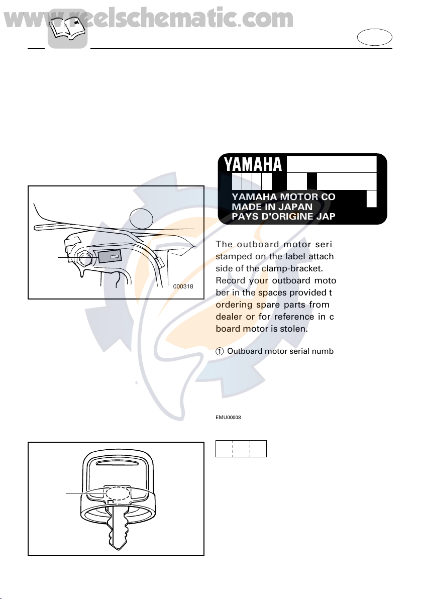
The outboard motor serial number is
stamped on the label attached to the port
side of the clamp-bracket.
Record your outboard motor serial number in the spaces provided to assist you in
ordering spare parts from your Yamaha
dealer or for reference in case your outboard motor is stolen.
E
q
123
000319
1 Outboard motor serial number
EMU00008
KEY NUMBER
If a main key switch is equipped with the
motor, the key identification number is
stamped on your key as shown in the
illustration. Record this number in the
space provided for reference in case you
need a new key.
1 Key number
1-1
EMISSION CONTROL INFORMATION
ENGINE FAMILY :
THIS ENGINE CONFORMS TO 2001 U.S. EPA REGULATIONS FOR MARINE SI ENGINES.
THIS ENGINE CONFORMS TO 2001 CALIFORNIA EMISSION REGULATIONS FOR SI MARINE ENGINES.
REFER TO THE OWNERS MANUAL FOR MAINTENANCE SPECIFICATIONS AND ADJUSTMENTS.
FELs :
SPARK PLUG :
DISPLACEMENT :
ADVERTISED POWER :
IDLE SPEED :
SPARK PLUG GAP (mm) :
FUEL : GASOLINE
VALVE LASH (mm) :
IN EX
cm
kw
g/kw-hr
rpm IN NEUTRAL
3
EM
Manufactured:
www.reelschematic.com
EMU01385
EMISSION CONTROL
INFORMATION
q
EMU01387
NORTH AMERICAN MODELS
w
000320
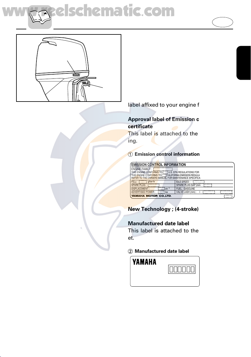
This engine conforms to U.S.
Environmental Protection Agency (EPA)
regulations for marine SI engines. See the
label affixed to your engine for details.
Approval label of Emission control
certificate
This label is attached to the bottom cowling.
1 Emission control information label
E
New Technology ; (4-stroke) EM
Manufactured date label
This label is attached to the clamp bracket.
2 Manufactured date label
1-2
www.reelschematic.com
EMU01389
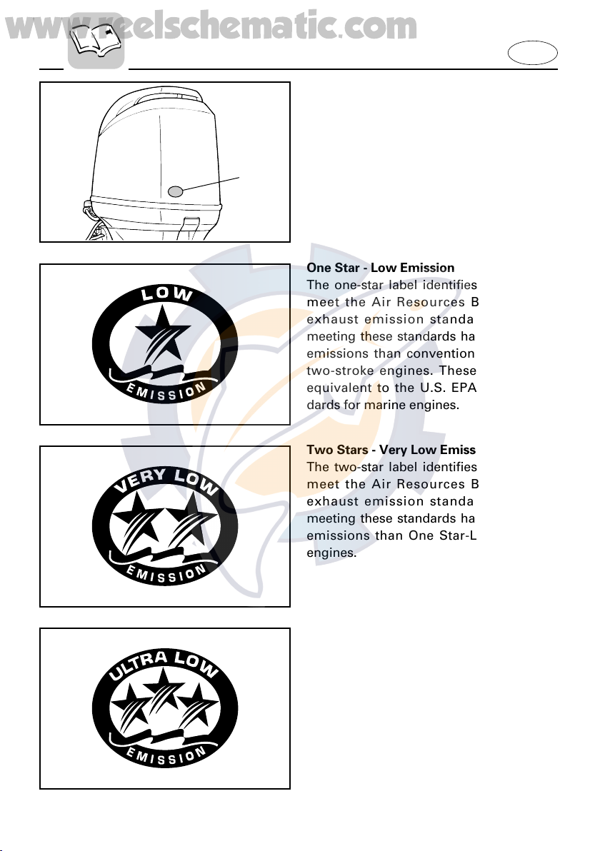
STAR LABELS
Your outboard motor is labeled with a
California Air Resources Board (CARB)
star label. See below for a description of
q
000848
your particular label.
1 Star label
One Star - Low Emission
The one-star label identifies engines that
meet the Air Resources Board’s 2001
exhaust emission standards. Engines
meeting these standards have 75% lower
emissions than conventional carbureted
two-stroke engines. These engines are
equivalent to the U.S. EPA’s 2006 standards for marine engines.
E
Two Stars - Very Low Emission
The two-star label identifies engines that
meet the Air Resources Board’s 2004
exhaust emission standards. Engines
meeting these standards have 20% lower
emissions than One Star-Low-Emission
engines.
Three Stars - Ultra Low Emission
The three-star label identifies engines that
meet the Air Resources Board’s 2008
exhaust emission standards. Engines
meeting these standards have 65% lower
emissions than One Star-Low-Emission
engines.
1-3
www.reelschematic.com
E
EMU00917
SAFETY
Q
8 Before mounting or operating the out-
board motor, read this entire manual.
Reading it should give you an understanding of the motor and its operation.
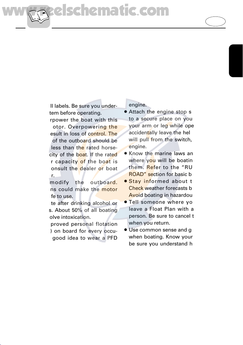
8 Before operating the boat, read any
owner’s or operator’s manuals supplied
with it and all labels. Be sure you under-
stand each item before operating.
8 Do not overpower the boat with this
outboard motor. Overpowering the
boat could result in loss of control. The
rated power of the outboard should be
equal to or less than the rated horse-
power capacity of the boat. If the rated
horsepower capacity of the boat is
unknown, consult the dealer or boat
manufacturer.
8 Do not modify the outboard.
Modifications could make the motor
unfit or unsafe to use.
8 Never operate after drinking alcohol or
taking drugs. About 50% of all boating
fatalities involve intoxication.
8 Have an approved personal flotation
device (PFD) on board for every occu-
pant. It is a good idea to wear a PFD
whenever boating. At a minimum, children and non-swimmers should always
wear PFDs, and everyone should wear
PFDs when there are potentially hazardous boating conditions.
8 Gasoline is highly flammable, and its
vapors are flammable and explosive.
Handle and store gasoline carefully.
Make sure there are no gas fumes or
leaking fuel before starting the engine.
INFORMATION
8 This product emits exhaust gases which
contain carbon monoxide, a colorless,
odorless gas which may cause brain
damage or death when inhaled.
Symptoms include nausea, dizziness,
and drowsiness. Keep cockpit and cabin
areas well ventilated. Avoid blocking
exhaust outlets.
8 Check throttle, shift, and steering for
proper operation before starting the
engine.
8 Attach the engine stop switch lanyard
to a secure place on your clothing, or
your arm or leg while operating. If you
accidentally leave the helm, the lanyard
will pull from the switch, stopping the
engine.
8 Know the marine laws and regulations
where you will be boating - and obey
them. Refer to the “RULES OF THE
ROAD” section for basic boating rules.
8 Stay informed about the weather.
Check weather forecasts before boating.
Avoid boating in hazardous weather.
8 Tell someone where you are going:
leave a Float Plan with a responsible
person. Be sure to cancel the Float Plan
when you return.
8 Use common sense and good judgment
when boating. Know your abilities, and
be sure you understand how your boat
handles under the different boating
conditions you may encounter. Operate
within your limits, and the limits of your
boat. Always operate at safe speeds,
and keep a careful watch for obstacles
and other traffic.
8 Always watch carefully for swimmers
during the engine operation.
8 Stay away from swimming areas.
1-4
www.reelschematic.com
8 When a swimmer is in the water near
you shift into neutral and shut off the
engine.
8 Be informed about boating safety.
Additional publications and information
can be obtained from many organizations, including the following:
United States Coast Guard
Consumer Affairs Staff (G-BC)
Office of Boating, Public, and Consumer
Affairs
U.S. Coast Guard Headquarters
Washington, D.C. 20593-0001
Boating Safety Hotline: 1-800-368-5647
National Marine Manufacturers
Association (NMMA)
401 N. Michigan Ave.
Chicago, Il 60611
E
Marine Retailers Association of America
155 N. Michigan Ave.
Chicago, Il 60601
1-5
q
w
000321
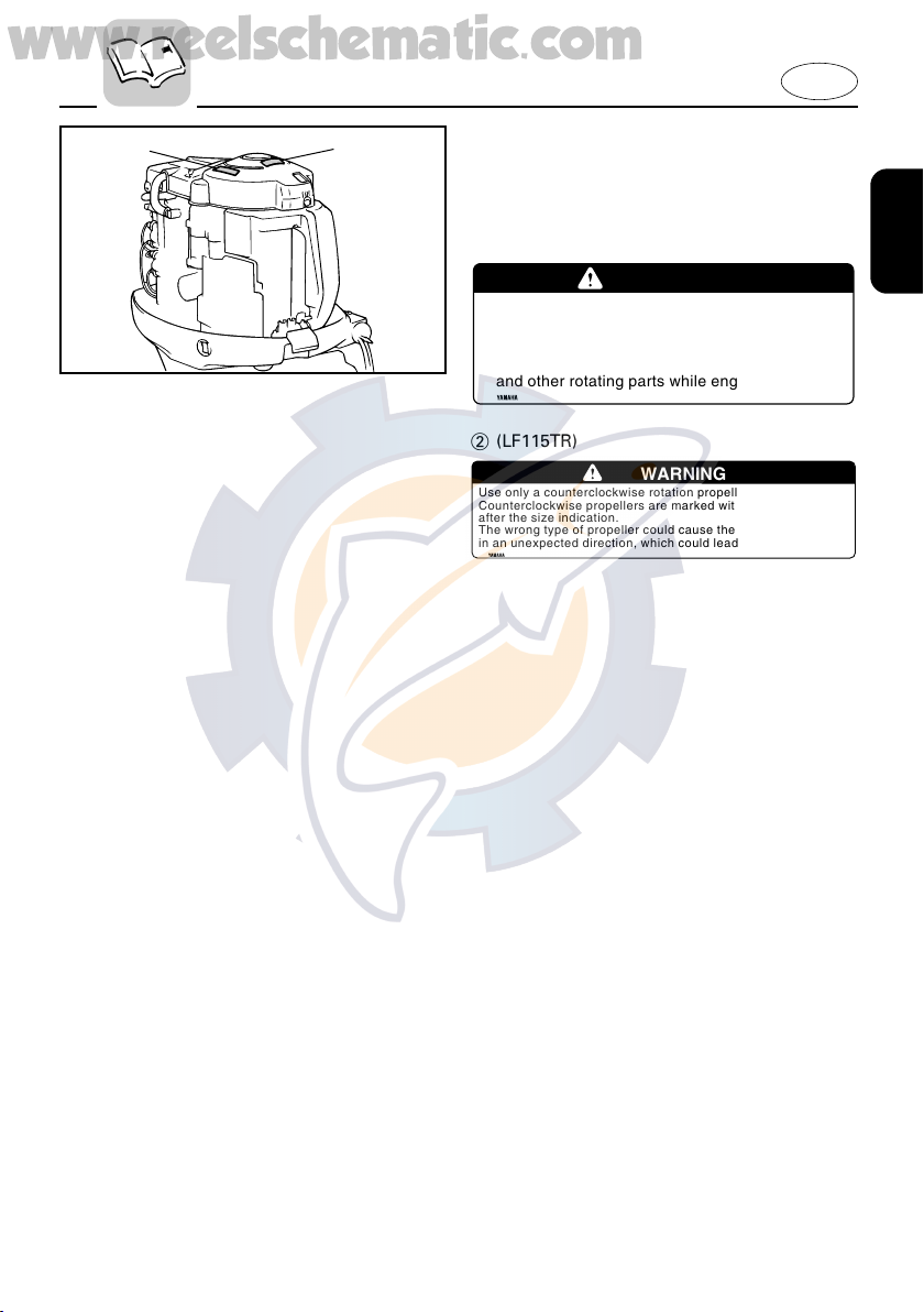
WARNING
8Be sure shift control is in neutral
before starting engine. (except 2HP)
8Do not touch or remove electrical parts
when starting or during operation.
8Keep hands,hair,and clothes away from flywheel
and other rotating parts while engine is running.
6A1-83625-41
Use only a counterclockwise rotation propeller with this engine.
Counterclockwise propellers are marked with a letter "L"
after the size indication.
The wrong type of propeller could cause the boat to go
in an unexpected direction, which could lead to an accident.
6K1-83623-41
WARNING
www.reelschematic.com
EMU00014
IMPORTANT LABELS
WARNING LABELS
1
2 (LF115TR)
E
1-6
www.reelschematic.com
E
EMU00015
BASIC BOATING RULES
(Rules of the road)
Just as there are rules which apply when
you are driving on streets and high ways,
there are waterway rules which apply
when you are driving your boat. These
rules are used internationally, and are
also enforced by the United States Coast
Guard and local agencies. You should be
aware of these rules, and follow them
whenever you encounter another vessel
on the water.
Several sets of rules prevail according to
geographic location, but are all basically
the same as the International Rules of the
Road. The rules presented here in your
Owner’s Manual are condensed, and have
been provided for your convenience only.
Consult your local U.S. Coast Guard
Auxiliary or Department of Motor
Vehicles for a complete set of rules gov-
erning the waters in which you will be
using your boat.
STEERING AND SAILING RULES AND
SOUND SIGNALS
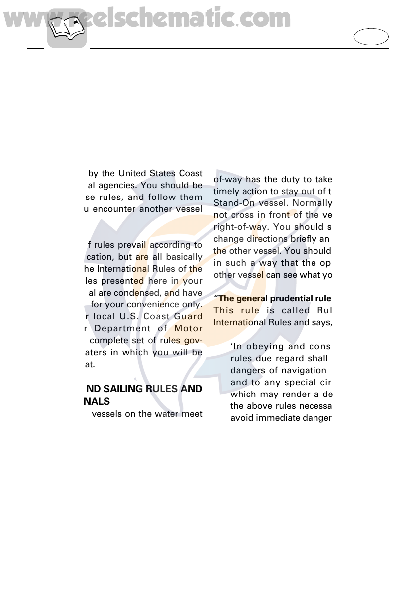
Whenever two vessels on the water meet
one another, one vessel has the right-ofway; it is called the “stand-on” vessel.
The vessel which does not have the rightof-way is called the “give-way” or “burdened” vessel. These rules determine
which vessel has the right-of-way, and
what each vessel should do.
Stand-on vessel
The vessel with the right-of-way has the
duty to continue its course and speed,
except to avoid an immediate collision.
When you maintain your direction and
speed, the other vessel will be able to
determine how best to avoid you.
Give-way vessel
The vessel which does not have the rightof-way has the duty to take positive and
timely action to stay out of the way of the
Stand-On vessel. Normally, you should
not cross in front of the vessel with the
right-of-way. You should slow down or
change directions briefly and pass behind
the other vessel. You should always move
in such a way that the operator of the
other vessel can see what you are doing.
“The general prudential rule”
This rule is called Rule 2 in the
International Rules and says,
‘In obeying and construing these
rules due regard shall be had to all
dangers of navigation and collision,
and to any special circumstances,
which may render a departure from
the above rules necessary in order to
avoid immediate danger.’
In other words, follow the standard rules
except when a collision will occur unless
both vessels try to avoid each other. If
that is the case, both vessels become
“Give-Way” vessels.
1-7
102045
www.reelschematic.com
E
RULES WHEN ENCOUNTERING
VESSELS
There are three main situations which you
may encounter with other vessels which
could lead to a collision unless the
Steering Rules are followed:
Meeting
(you are approaching another vessel
head-on)
Crossing
(you are traveling across the other
vessel’s path)
Overtaking
(you are passing or being passed by
another vessel)
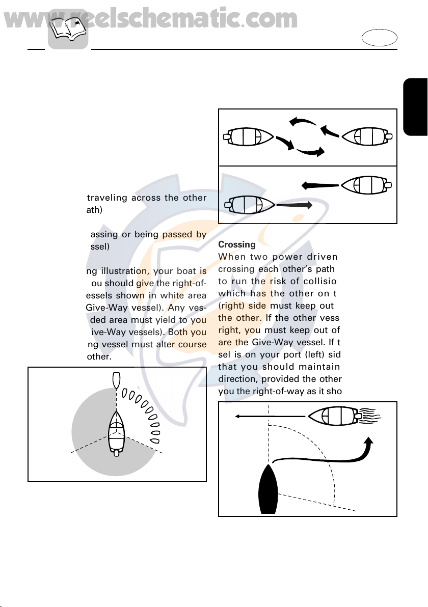
In the following illustration, your boat is
in the center. You should give the right-of-
way to any vessels shown in white area
(you are the Give-Way vessel). Any ves-
sels in the shaded area must yield to you
(they are the Give-Way vessels). Both you
and the meeting vessel must alter course
to avoid each other.
keep the other vessel on your port (left)
side. This rule doesn’t apply if both of you
will clear one another if you continue on
your set course and speed.
102044
Crossing
When two power driven vessels are
crossing each other’s path close enough
to run the risk of collision, the vessel
which has the other on the starboard
(right) side must keep out of the way of
the other. If the other vessel is on your
right, you must keep out of its way; you
are the Give-Way vessel. If the other vessel is on your port (left) side, remember
that you should maintain course and
direction, provided the other vessel gives
you the right-of-way as it should.
Meeting
If you are meeting another power vessel
head on, and are close enough to run the
risk of collision, neither of you has the
right-of-way! Both of you should alter
course to avoid an accident. You should
102046
Overtaking
If you are passing another vessel, you are
the “Give-Way” vessel. This means that
1-8
www.reelschematic.com
E
the other vessel is expected to maintain
its course and speed. You must stay out
of its way until you are clear of it.
Likewise, if another vessel is passing you,
you should maintain your speed and
direction so that the other vessel can steer
itself around you.
OTHER SPECIAL SITUATIONS
There are three other rules you should be
aware of when driving your boat around
other vessels.
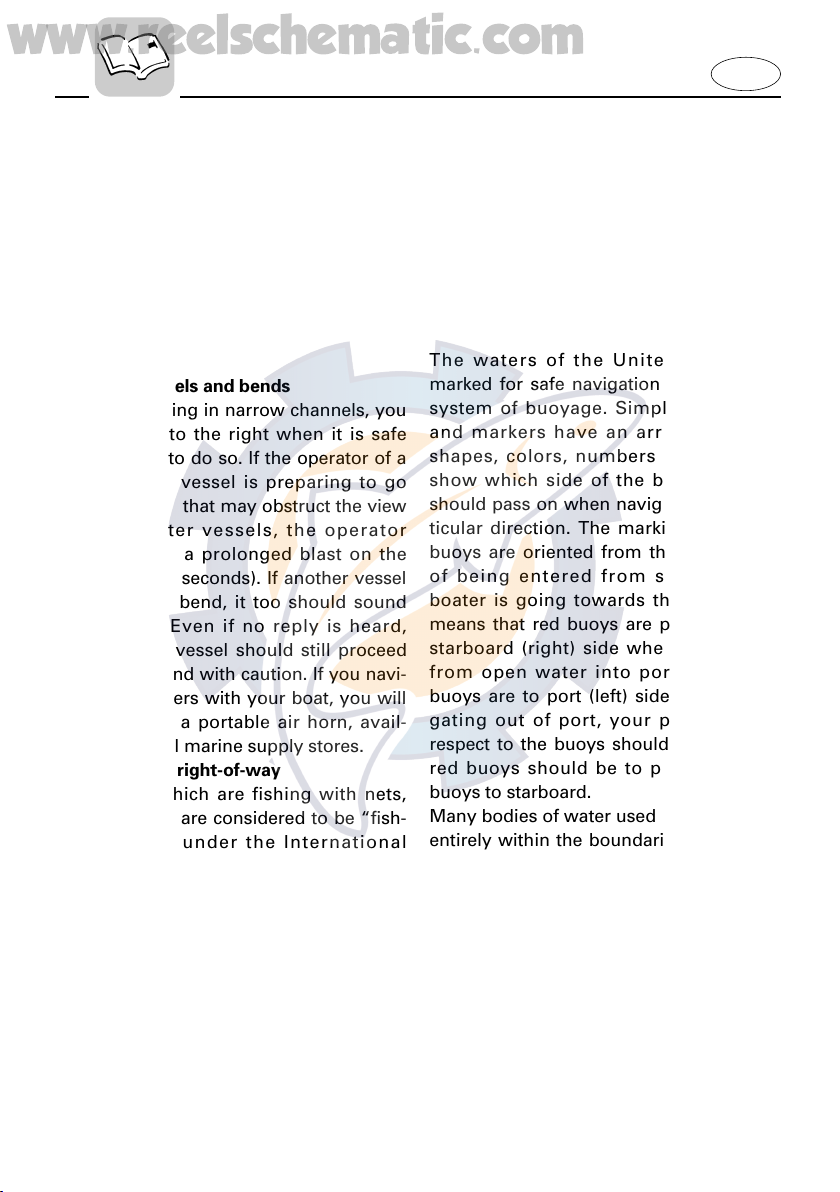
Narrow channels and bends
When navigating in narrow channels, you
should keep to the right when it is safe
and practical to do so. If the operator of a
power-driven vessel is preparing to go
around a bend that may obstruct the view
of other water vessels, the operator
should sound a prolonged blast on the
whistle (4 to 6 seconds). If another vessel
is around the bend, it too should sound
the whistle. Even if no reply is heard,
however, the vessel should still proceed
around the bend with caution. If you navi-
gate such waters with your boat, you will
need to carry a portable air horn, avail-
able from local marine supply stores.
Fishing vessel right-of-way
All vessels which are fishing with nets,
lines or trawls are considered to be “fish-
ing vessels” under the International
Rules. Vessels with trolling lines are not
considered fishing vessels. Fishing vessels have the right-of-way regardless of
position. Fishing vessels cannot, however, impede the passage of other vessels in
narrow channels.
Sailing vessel right-of-way
Sailing vessels should normally be given
the right-of-way. The exceptions to this
are:
1. When the sailing vessel is overtaking
the power-driven vessel, the powerdriven vessel has the right-of-way.
2. Sailing vessels should keep clear of
any fishing vessel.
3. In a narrow channel, a sailing vessel
should not hamper the safe passage
of a power-driven vessel which can
navigate only in such a channel.
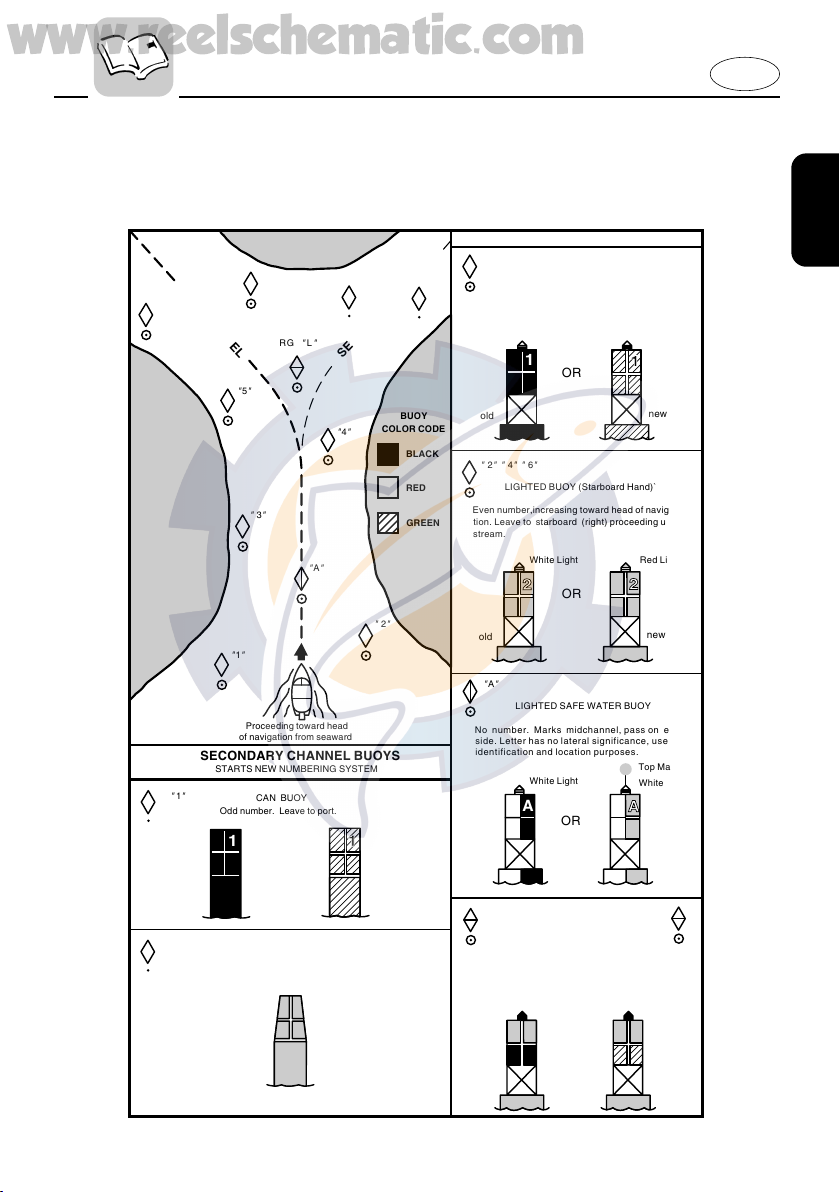
Reading buoys and other markers
The waters of the United states are
marked for safe navigation by the lateral
system of buoyage. Simply put, buoys
and markers have an arrangement of
shapes, colors, numbers and lights to
show which side of the buoy a boater
should pass on when navigating in a particular direction. The markings on these
buoys are oriented from the perspective
of being entered from seaward (the
boater is going towards the port). This
means that red buoys are passed on the
starboard (right) side when proceeding
from open water into port, and black
buoys are to port (left) side. When navigating out of port, your position with
respect to the buoys should be reversed;
red buoys should be to port and black
buoys to starboard.
Many bodies of water used by boaters are
entirely within the boundaries of a particular state. The Uniform State Waterway
Marking System has been devised for
these waters. This system uses buoys and
signs with distinctive shapes and colors
to show regulatory or advisory information. These markers are white with black
letters and orange boarders. They signify
speed zones, restricted areas, danger
areas, and general information.
1-9
1
1
A
1
1
Proceeding toward head
of navigation from seaward
CAN BUOY
Odd number. Leave to port.
OR
SECONDARY CHANNEL BUOYS
STARTS NEW NUMBERING SYSTEM
old new
C " 1
"
NUN BUOY
Even number. Leave to starboard
N
"
2
"
No change
BUOY
COLOR CODE
BLACK
RED
GREEN
"
A
"
"
2
"
"
1
"
"
3
"
"
4
"
"
5
"
"
7
"
N
"
2
"
"
6
"
C
"
1
"
RB
"
L
"
RG
"
L
"
or
SECONDARY CHANNEL
MAIN CHANNEL
old
new
2
2
2
A
L
L
Odd number. increasing toward head of naviga-
MAIN CHANNEL BUOYS
"
1
" "
3
" "
5
" "
7
"
tion.Leave to port (left) proceeding upstream.
LIGHTED BUOY (Port Hand)`
White Light
Green Light
old
new
old
new
old
new
LIGHTED BUOY (Starboard Hand)`
"
2
" "
4
" "
6
"
Even number,increasing toward head of navigation. Leave to starboard (right) proceeding upstream.
White Light Red Light
"
A
"
LIGHTED SAFE WATER BUOY
No number. Marks midchannel, pass on either
side. Letter has no lateral significance, used for
No number. Topmost band red
-
preferred
Top Mark
White Light
White Light
OR
OR
LIGHTED PREFERRED CHANNEL TO
RB
"
L
"
RG
"
L
"
PORT BUOY
identification and location purposes.
channel is to left of buoy. Letter has no lateral
significance, used for identification and location
purposes.
Red Light
Red or
White Light
OR
102052
www.reelschematic.com
Remember, markings may vary by geographic location. Always consult local
boating authorities before driving your
boat in unfamiliar waters.
E
1-10
www.reelschematic.com
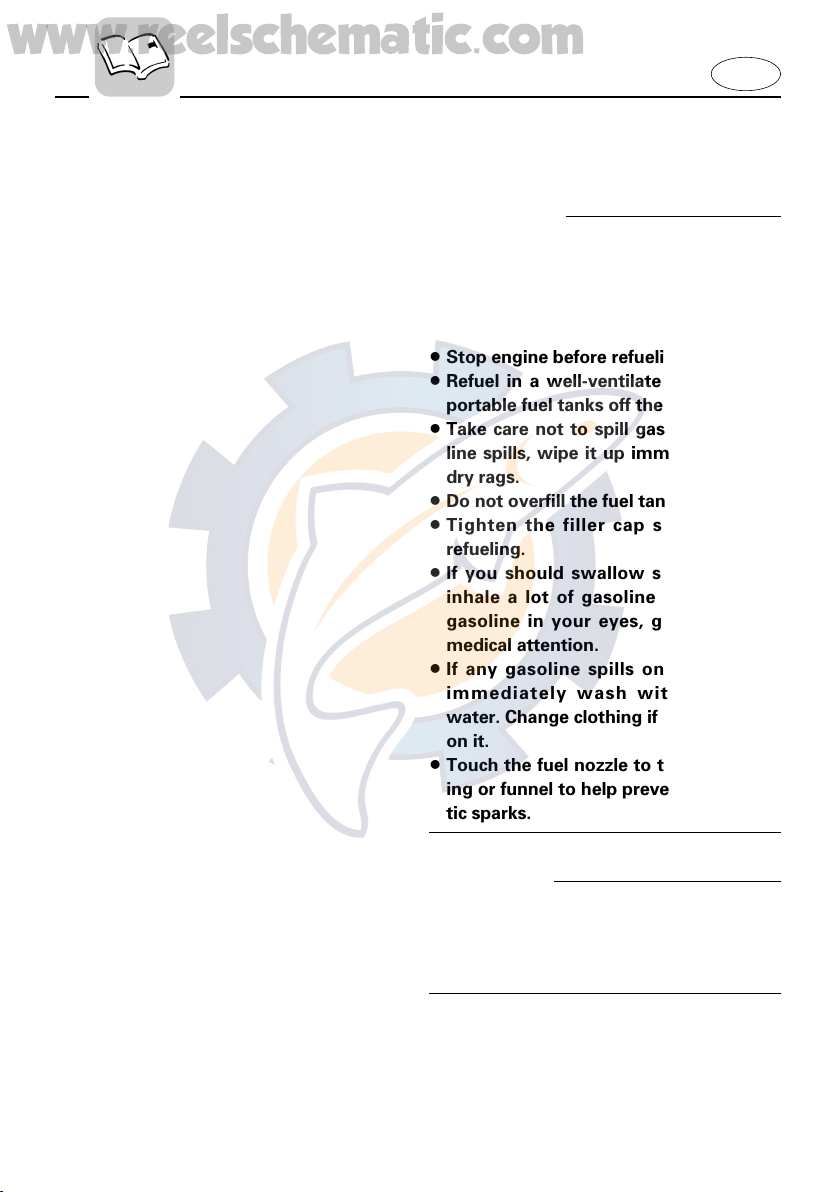
EMU00016
FUELING INSTRUCTIONS
w
GASOLINE AND ITS VAPORS ARE HIGHLY FLAMMABLE AND EXPLOSIVE!
8 Do not smoke when refueling, and
keep away from sparks, flames, or
other sources of ignition.
8 Stop engine before refueling.
8 Refuel in a well-ventilated area. Refuel
portable fuel tanks off the boat.
8 Take care not to spill gasoline. If gaso-
line spills, wipe it up immediately with
dry rags.
8 Do not overfill the fuel tank.
8 Tighten the filler cap securely after
refueling.
8 If you should swallow some gasoline
inhale a lot of gasoline vapor, or get
gasoline in your eyes, get immediate
medical attention.
8 If any gasoline spills onto your skin,
immediately wash with soap and
water. Change clothing if gasoline spills
on it.
8 Touch the fuel nozzle to the filler open-
ing or funnel to help prevent electrostatic sparks.
E
cC
Use only new clean gasoline which has
been stored in clean containers and is not
contaminated with water or foreign matter.
1-11
www.reelschematic.com
EMU01804
GASOLINE
Recommended gasoline:
Regular unleaded gasoline with a
minimum octane rating of 86 (Pump
Octane Number) = (R+M)/2
If knocking or pinging occurs, use a different brand of gasoline or premium unleaded fuel.
EMU00027
Gasohol
There are two types of gasohol: gasohol
containing ethanol and that containing
methanol. Gasohol containing ethanol
can be used if ethanol content does not
exceed 10% and the fuel meets minimum
octane ratings. Gasohol containing
methanol is not recommended by
Yamaha because it can cause fuel system
damage or engine performance problems.
E
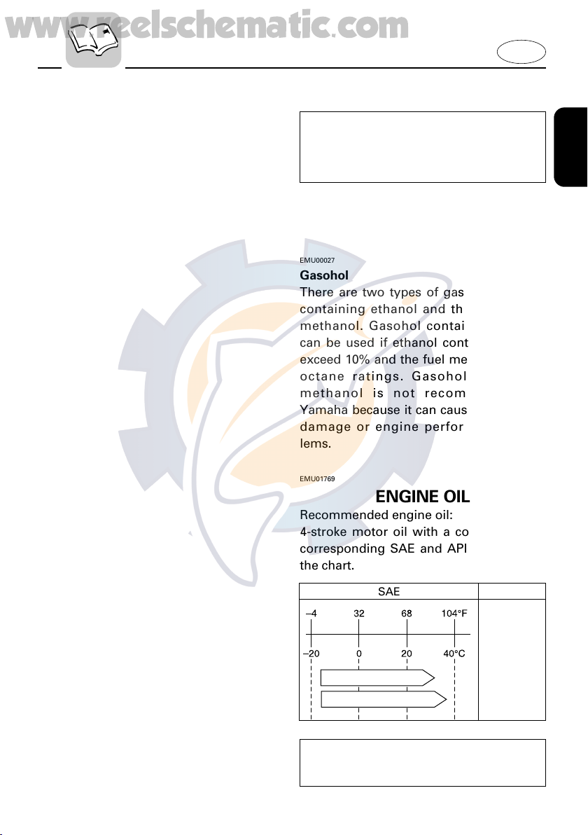
EMU01769
ENGINE OIL
Recommended engine oil:
4-stroke motor oil with a combination of
corresponding SAE and API as shown in
the chart.
SAE API
10W-30
10W-40
Engine oil quantity:
See Chapter 4, “Specifications.”
1-12
SE
SF
SG
SH
SJ

www.reelschematic.com
cC
All 4-stroke engines are shipped from the
factory without engine oil.
001162
EMU01775
BATTERY REQUIREMENT
cC
Do not use a battery that does not meet
the specified capacity. If a battery which
does not meet specifications is used, the
electric system could perform poorly or
be overloaded, causing electric system
damage.
E
For electric start models, choose a battery
which meets the following specifications.
EMU01860
Minimum cold cranking amps
(CCA/SAE): 380 amps at -18°C (-0.4°F)
Minimum marine cranking amps
(MCA/ABYC): 502 amps at 0°C (32°F)
Minimum reserve capacity (RC/SAE):
124 minutes
EMU01787
NOTE:
The engine cannot be started if battery
voltage is too low.
1-13
www.reelschematic.com
EMU01395
PROPELLER SELECTION
The performance of your outboard motor
will be critically affected by your choice of
propeller, as an incorrect choice could
adversely affect performance and could
also seriously damage the motor. Engine
speed depends on the propeller size and
boat load. If engine speed is too high or
too low for good engine performance,
this will have an adverse effect on the
engine.
Yamaha outboard motors are fitted with
propellers chosen to perform well over a
range of applications, but there may be
uses where a propeller with a different
pitch would be more appropriate. For a
greater operating load, a smaller-pitch
propeller is more suitable as it enables
the correct engine speed to be maintained. Conversely, a larger-pitch propeller is more suitable for a smaller operating load.
E
Yamaha dealers stock a range of propellers, and can advise you and install a
propeller on your outboard that is best
suited to your application.
1-14
602014
13 x 17 - K
qwe
www.reelschematic.com
NOTE:
At full throttle and under a maximum
boat load, the engine’s rpm should be
within the upper half of the full throttle
operating range, as listed in “SPECIFICATIONS” on page 4-1. Select a propeller
which fulfills this requirement.
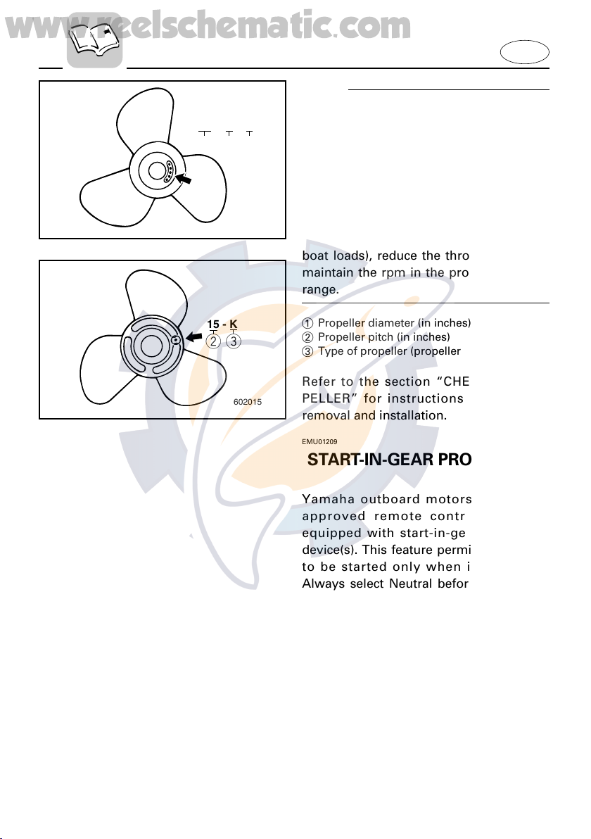
If operating under conditions which allow
the engine’s rpm to rise above the maximum recommended range (such as light
boat loads), reduce the throttle setting to
maintain the rpm in the proper operating
range.
E
15 - K
we
602015
1 Propeller diameter (in inches)
2 Propeller pitch (in inches)
3 Type of propeller (propeller mark)
Refer to the section “CHECKING PROPELLER” for instructions on propeller
removal and installation.
EMU01209
START-IN-GEAR PROTECTION
Yamaha outboard motors or Yamaha
approved remote control units are
equipped with start-in-gear protection
device(s). This feature permits the engine
to be started only when it is Neutral.
Always select Neutral before starting the
engine.
1-15
www.reelschematic.com
EMU00037
Chapter 2
BASIC COMPONENTS
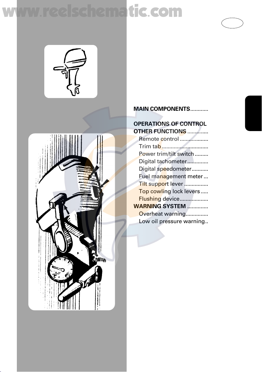
MAIN COMPONENTS..............................2-1
OPERATIONS OF CONTROLS AND
OTHER FUNCTIONS ................................2-2
Remote control .....................................2-2
Trim tab .................................................2-7
Power trim/tilt switch ...........................2-8
Digital tachometer................................2-9
Digital speedometer...........................2-12
Fuel management meter ...................2-15
Tilt support lever ................................2-18
Top cowling lock levers .....................2-19
Flushing device...................................2-19
WARNING SYSTEM ..............................2-20
Overheat warning...............................2-20
Low oil pressure warning..................2-21
E
1
2
3
4
5
6
TRIP TIME BATT
Km/h
knot
mph
km
mile
SPEED
YAMAHA
set
mode
q
w
e
r
t
y
u
i
o
w
YAMAHA
set
mode
P S
mpg
Km/L
gph
I/h
ECON SYNCTTL
FUEL MANAGEMENT
!0
!1
!2
!3
!4
!5 !6
www.reelschematic.com
EMU01206
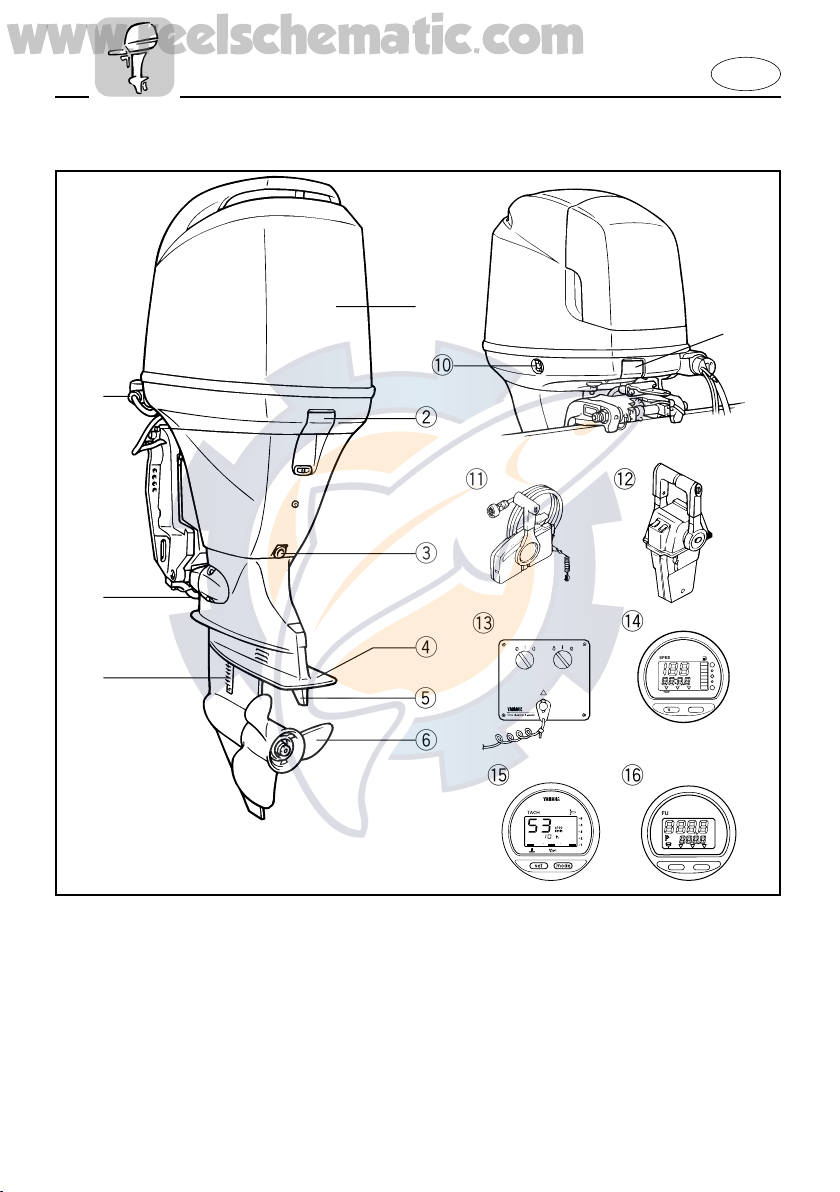
MAIN COMPONENTS
E
1 Top cowling
2 Top cowling lock levers
3 Engine oil drain bolt
4 Anti-cavitation plate
5 Trim tab (Anode)
* 6 Propeller
7 Cooling water inlet
8 Anode
9 Flushing device
0 Power trim and tilt switch
* q Remote control box (Side mount type)
* w
Remote control box (Binnacle mount type)
* e Switch panel (For use with w)
* r Digital speedometer
* t Digital tachometer
* y Fuel management meter
* May not be exactly as shown; also may not
be included as standard equipment on all
models.
2-1
000322
w
q
e
t
y
u
i
www.reelschematic.com
E
A
EMU00039
OPERATIONS OF CONTROLS
AND
OTHER FUNCTIONS
EMU01273
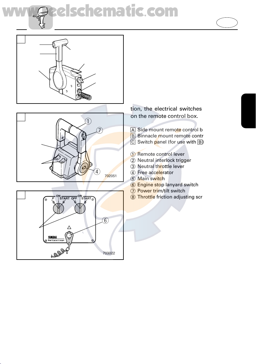
REMOTE CONTROL
Both the shifter and the throttle are actuated by the remote control lever. In addition, the electrical switches are mounted
B
q
u
i
u
r
702051
C
ON
ON
STARTOFF
STARTOFF
on the remote control box.
å Side mount remote control box
∫ Binnacle mount remote control box
ç Switch panel (for use with ∫)
1 Remote control lever
2 Neutral interlock trigger
3 Neutral throttle lever
4 Free accelerator
5 Main switch
6 Engine stop lanyard switch
7 Power trim/tilt switch
8 Throttle friction adjusting screw
y
t
703022
2-2
R
N
F
q
w
e
r
t
y
u
u
t
r
y
701031
www.reelschematic.com
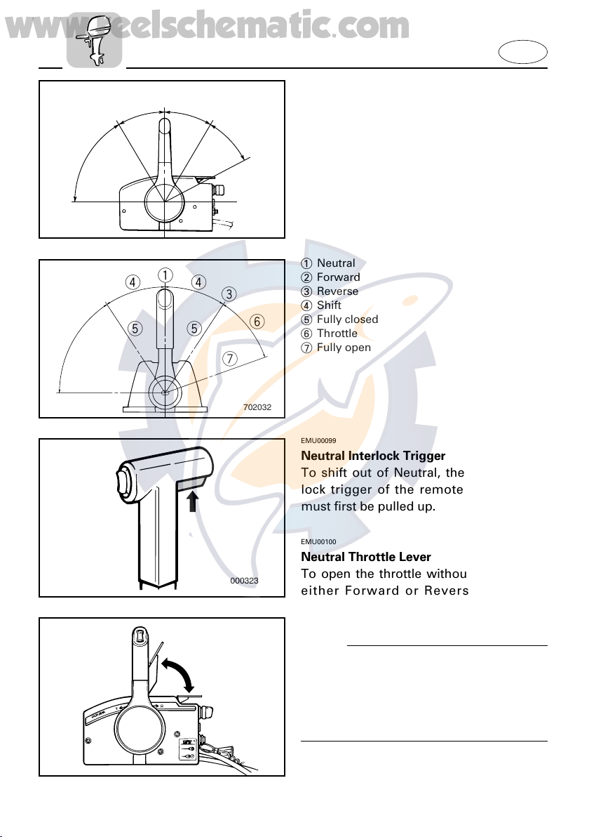
EMU00098
Remote Control Lever
Moving the lever forward from the
Neutral position engages Forward gear.
Pulling the lever back from Neutral
engages Reverse. The engine will continue to run at idle until the lever is moved
about 35° (a detent can be felt). Moving
the lever farther opens the throttle, and
the engine will begin to accelerate.
1 Neutral
2 Forward
3 Reverse
4 Shift
5 Fully closed
6 Throttle
7 Fully open
EMU00099
Neutral Interlock Trigger
To shift out of Neutral, the neutral interlock trigger of the remote control lever
must first be pulled up.
u
w
q
rr
e
tty
y
u
702032
E
EMU00100
Neutral Throttle Lever
000323
N
q
w
000324
To open the throttle without shifting into
either Forward or Reverse, place the
remote control lever in the Neutral position and lift the neutral throttle lever.
NOTE:
The neutral throttle lever will operate only
when the remote control lever is in
Neutral. The remote control lever will
operate only when the neutral throttle
lever is in the closed position.
1 Fully open
2 Fully closed
2-3
ON
STARTOFF
701021
www.reelschematic.com
EMU00101
Main switch
The main switch controls the ignition system; its operation is described below.
8 OFF
Electrical circuits switched off.
(The key can be removed.)
8 ON
Electrical circuits switched on.
(The key cannot be removed.)
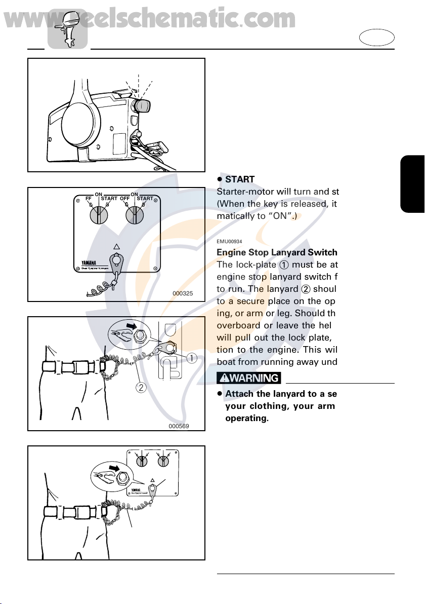
8 START
ON
ON
STARTOFF
STARTOFF
000325
w
000569
ON
ON
STARTOFF
STARTOFF
q
w
000715
Starter-motor will turn and start engine.
(When the key is released, it returns automatically to “ON”.)
EMU00934
Engine Stop Lanyard Switch
The lock-plate 1 must be attached to the
engine stop lanyard switch for the engine
to run. The lanyard 2 should be attached
to a secure place on the operator’s clothing, or arm or leg. Should the operator fall
overboard or leave the helm, the lanyard
will pull out the lock plate, stopping ignition to the engine. This will prevent the
q
boat from running away under power.
w
8 Attach the lanyard to a secure place on
your clothing, your arm or leg while
operating.
8 Do not attach the lanyard to clothing
that could tear loose. Do not route the
lanyard in such a way that it could
become entangled, preventing it from
functioning.
8 Avoid accidentally pulling the lanyard
during normal operation. Loss of
engine power means the loss of most
steering control. Also, without engine
power, the boat could slow rapidly.
This could cause people and objects in
the boat to be thrown forward.
E
2-4
UP
DN
701034
UP
DN
www.reelschematic.com
NOTE:
The engine cannot be started with the
lock-plate removed.
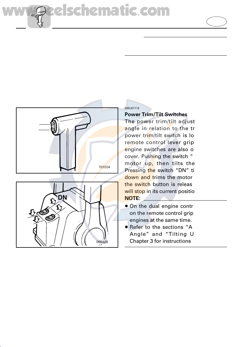
EMU01112
Power Trim/Tilt Switches
The power trim/tilt adjusts the motor
angle in relation to the transom. The
power trim/tilt switch is located on the
remote control lever grip. Individualengine switches are also on the control
cover. Pushing the switch “UP” trims the
motor up, then tilts the motor up.
Pressing the switch “DN” tilts the motor
down and trims the motor down. When
the switch button is released, the motor
will stop in its current position.
DN
UP
000328
NOTE:
8 On the dual engine control, the switch
on the remote control grip controls both
engines at the same time.
8 Refer to the sections “Adjusting Trim
Angle” and “Tilting Up/Down” in
Chapter 3 for instructions on usage.
E
2-5
702043
35°
q
w
e
www.reelschematic.com
EMU00106
Free Accelerator
To open the throttle without shifting into
either Forward or Reverse, push the free
accelerator button and turn the remote
control lever.
NOTE:
8 The free accelerator button can be oper-
ated only when the remote control lever
is in the Neutral position.
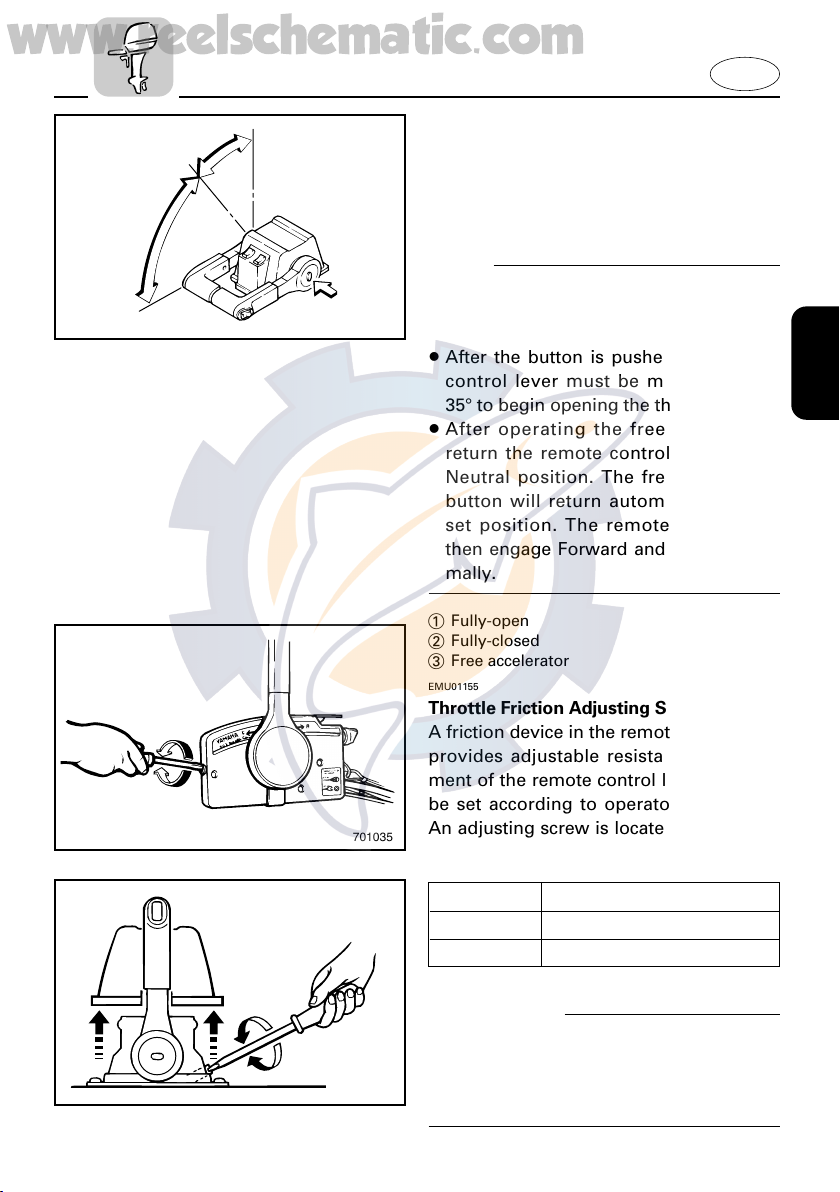
8 After the button is pushed, the remote
control lever must be moved at least
35° to begin opening the throttle.
8 After operating the free accelerator,
return the remote control lever to the
Neutral position. The free accelerator
button will return automatically to its
set position. The remote control will
then engage Forward and Reverse normally.
1 Fully-open
2 Fully-closed
3 Free accelerator
EMU01155
Throttle Friction Adjusting Screw
A friction device in the remote control box
provides adjustable resistance to movement of the remote control lever, and can
be set according to operator preference.
701035
An adjusting screw is located on the front
of the remote control box.
E
702035
Resistance Screw
Increase Turn clockwise
Decrease Turn counterclockwise
w
Do not overtighten the friction adjusting
screw. If there is too much resistance, it
may be difficult to move the lever, which
could result in an accident.
2-6
q
w
e
603014
www.reelschematic.com
EMU00113
TRIM TAB
The trim tab should be adjusted so that
the steering control can be turned to
either the right or left by applying the
same amount of force.
w
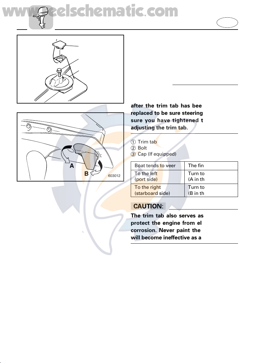
An improperly adjusted trim tab may
cause difficult steering. Always test run
after the trim tab has been installed or
replaced to be sure steering is correct. Be
sure you have tightened the bolt after
adjusting the trim tab.
1 Trim tab
2 Bolt
3 Cap (If equipped)
E
A
B
603012
Boat tends to veer The fin of trim tab
To the left Turn to the left
(port side) (A in the figure)
To the right Turn to the right
(starboard side) (B in the figure)
cC
The trim tab also serves as an anode to
protect the engine from electrochemical
corrosion. Never paint the trim tab as it
will become ineffective as an anode.
2-7
UP
DOWN
000302
www.reelschematic.com
EMU01125
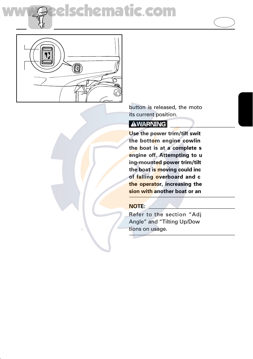
POWER TRIM/TILT SWITCH
The power trim/tilt adjusts the motor
angle in relation to the transom. The
power trim/tilt switch is located on the
side of the bottom engine cowling.
Pushing the switch “UP” trims the motor
up, then tilts the motor up. Pressing the
switch “DN” tilts the motor down and
trims the motor down. When the switch
button is released, the motor will stop in
its current position.
w
Use the power trim/tilt switch located on
the bottom engine cowling only when
the boat is at a complete stop with the
engine off. Attempting to use the cowling-mounted power trim/tilt switch while
the boat is moving could increase the risk
of falling overboard and could distract
the operator, increasing the risk of collision with another boat or an obstacle.
E
NOTE:
Refer to the section “Adjusting Trim
Angle” and “Tilting Up/Down” for instructions on usage.
2-8
q
t
w
r
001081
e
y
u
www.reelschematic.com
EMU01617
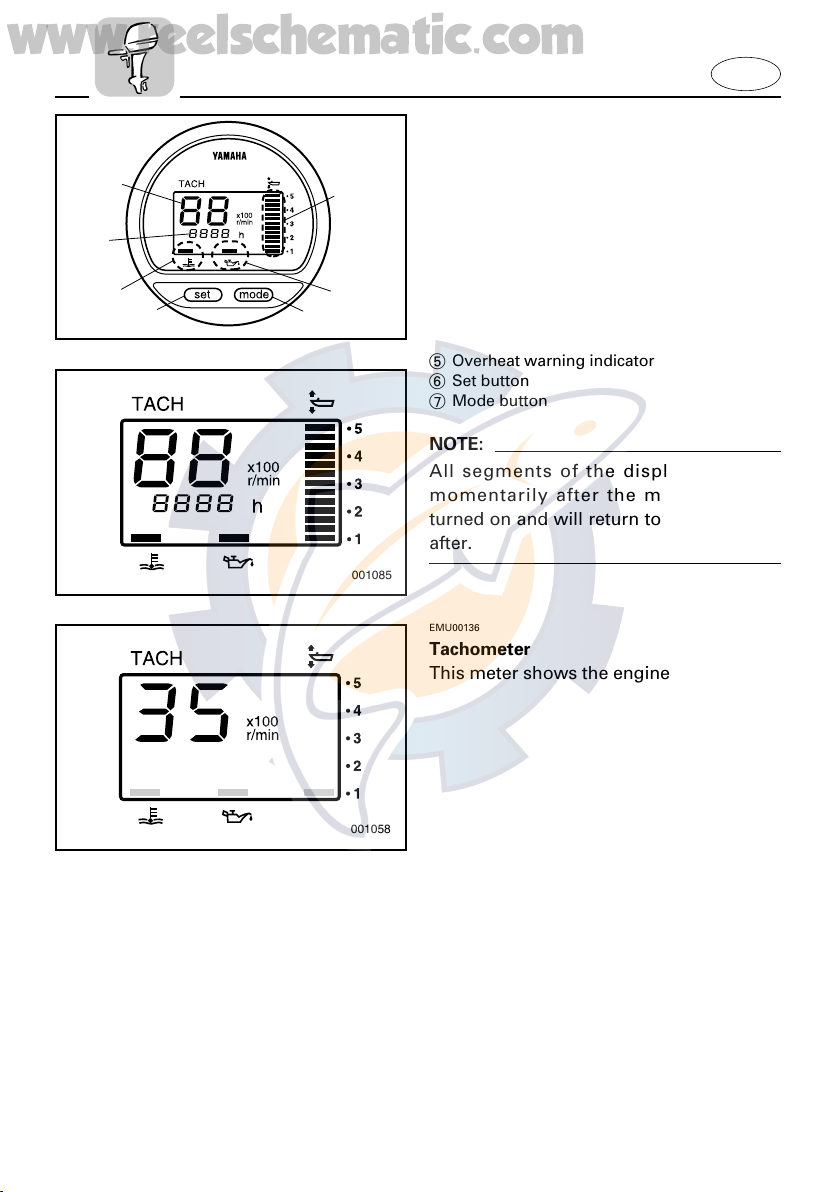
DIGITAL TACHOMETER
This gauge contains the tachometer, trim
meter, hour meter, low oil pressure warning indicator, and the overheat warning
indicator.
1 Tachometer
2 Trim meter
3 Hour meter
4 Low oil pressure warning indicator
5 Overheat warning indicator
6 Set button
7 Mode button
NOTE:
All segments of the display will light
momentarily after the main switch is
turned on and will return to normal thereafter.
001085
EMU00136
Tachometer
This meter shows the engine speed.
E
001058
2-9
 Loading...