


_YAMAHA
supp
Frame
[
Engine
LIT
-12618-00-22
serial number: 8J5-038101
serial number: S246-038101 ~ S246-049999
~
8J5-049999 ]
8J5-28197-10

CONTENTS
1980 ET250D
(
(
c
1.
NEW SERVICE PROCEDURE .....................
2.
MAINTENANCE INTERVALS
3.
SPECiFiCATIONS
4.
SPECIAL TOOLS ...........
5.
WIRING
DIAGRAM
6. WIRE ROUTING
CABLE
1.
NEW
(N
ew service procedure applied
A.
Primary
For better
SERVICE
sheave
clutch op eration and durability, a
DIAGRAM
.....
........
.....
.........................................
.. ..
......
....
.......
...........
........................................................
DIAGRAM/PIPING
...
........
...................
PROCEDURE
to
the
1980
ET250D)
new
............
...........
.............
............
................................. 1
...
...............
...
....................
..........
...
...................
....
...........
...
AND
CONTROL
.... ..
........................
...
...................
clutch has been adopped.
..
6
.............. 8
....
...
......
13
........
...
...
14
....
15
C
C
C
2
1.
Primary fixed sheave
2_
Primary sliding sheave
3 _
Bushing (Large)
4_
Cap
5_
Bushing (Small)
6_
Bolt
7_
Bolt
8_
Spring
20
4
5
9 _
10_
11.
12
13
14_
15_
16_
17_
18_
19_
20_
21.
22_
23_
24_
Spider
Sl
ider
Pin
_
Plate
_
Weight
Collar
Collar
Bolt
Plate
Cotter
Compr
Cam
Hexagon
U-
nut
Plate
Plate
washer
with
hole
washer
washer
pin
ession spring
bolt
washer
washer
-
1-

1980
ET250D
1.
Removal
a.
Remove the
bolt
using
primary
the
sheave holder.
sheave
mounting
Tool name
Sheave
1.
Sheave
b. Remove the
using the
bolt
Primary fixed sheave puller
bolt
(M
holder
holder
and
primary
Tool name
18
Pl.5)
primary
primary
Tool No.
90890-01880
sheave assembly,
fixed sheave puller
sheave holding tool.
Tool No.
90890-01881
b.
Install
the
Sheave
the
sheave sub-assembly
primary
Tool name
sub-assembly
sheave .
tool
tool
Tool No .
90890-01879
to
1.
Primary fixed sheave
puller
bolt
2. Disassembly
a.
Separate
from
the
sliding sheave assembly
the
fixed sheave by
sliding sheave counterclockwise.
rotating
the
1 Sheave sub-assembly
c.
Loosen the six
tool
bolts
primary sheave cap and
d.
Remove
The
sheave cap
the
primary
sheave subassembly tool.
sheave cap and sliding
now
be disassembled.
3. Inspection
a.
Check the tapered ends
shaft and
scratches.
primary
If scratched unduly, replac
fixed sheave for
If scratches are minor, burnish
emery
b.
Check the
and
cloth.
primary
sliding sheave
sheave cap bushing
bushing
beyond tolerance, replace
bushing clearance,
Small bushing
25
mm
Inside
Outside
0.
0.25
(0.01 in)
mm
(0 .01 in) 0.
securing the
sliding sheave .
of
the
crank-
with
for
wear.
the
bushing.
limit
Large bushing
0.
25
mm
(0 .01 in)
25
mm
(0.01 in)
)
e.
If
)
-
2-
r
c
(
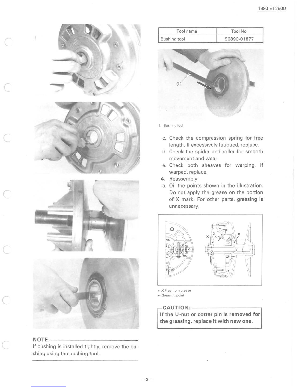
Tool name Tool No.
Bushing
1. Bushing tool
e.
4. Reassembly
a.
tool
c.
Check the compression spring for free
length.
d.
Check the spider and roller
movement
Check both sheaves
warped, replace.
Oil the points
Do
of
unnecessary.
If
excessively fatigued, rep!ace.
and wear.
shown
not
apply the grease on the portion
X mark. For
other
90890-01877
for
for
warping.
in
the
illustration .
parts, greasing is
1980 ET250D
smooth
If
c
c
NOTE:--------------------------
If
c
bushing is installed tightly, remove the bu-
shing using the bushing
tool.
-3-
+-
X Free
from
grease
+-
Greasing
point
CAUTION:-------------------,
If
the U -nut
the
greasing,
or
cotter
replace
pin
it
is
with
removed
new
for
one.

1980 ET25lJD
NOTE:--
When
the
the X mark
the
b.
Install
ing
primary
spider.
the
component
sheave and the sheave cap.
----
------------------
installing
the
primary
sliding sheave, be sure
on
the
sheave cap
parts
sheave cap
to
with
the
to
that
slid-
--
to
align
on
e.
Clean the
and fixed sheav
f.
Fit
the
fixed sheave
tion
of
crankshaft.
Apply
g.
of
surface
engine oil
primary
with
taper
ed
portions
e.
to
to
the
sheave
spring washer.
bolt
of
crankshaft
the
tapered por-
threaded
and its
portion
contact
c.
Install
tighten
d.
Tighten
and remove
Tightening
CAUTION:
Make
assembly slides in
fixed sheave boss.
the
the cap.
the
torque:
1.1
m-kg (8 ft-Ib)
sure
that
sheave subassembly
six
primary
the
subassembly tool.
--------------,
the
tool
and
sheave cap
primary sheave cap
contact
with
bolts
the
h. Tighten
bolt
using
tool.
the
primary
primary
,
sheave
sheave cap
mounting
holding
-4-

19
80
ET250D
Tightening
First
A
Retightened
B.
B.
Starter
The air
will
there
cording ly, the insert for
duct
on
torque
tight
en the
then
loosen it.
A.:
10m-kg
B.
: 6
m-kg
duct
is
no
be no
the
problem
starter case is
:
bolt
bolt
to
(72
(43.5
longer provided because
to a torque
a final torque
.5
ft-Ibl
ft-Ibl
of
overheating. Ac-
mounting
no
of
longer used.
of
of
the
air
1.
Air
duct ... No l
2.
3.
4.
Screw
Plain
Starter
...
wash
case
NOTE:------
. The
1979
installing
model can also be used
the
onger
No longer used
er
...
------
air
duct
used
No longer used
--------
.
------
without
- 5 -
 Loading...