

Page 1
DX Simulator
Manual
Important Notices
The DX Simulator provides an easy, intuitive way to edit and create your own original DX
voices for the PLG150-DX Advanced DX/TX Plug-in Board.
• Do not use any of the panel controls on an external tone generator while editing the DX
voices with the DX Simulator, since this may inadvertently change the settings of the PLG150DX.
Copyright Notices
• The software and this owner’s manual are the exclusive copyrights of Yamaha Corporation.
• Copying of the software or reproduction of this manual in whole or in part by any means is
expressly forbidden without the written consent of the manufacturer.
• Copying of the commercially available music sequence data and/or digital audio files is
strictly prohibited except for your personal use.
Trade Marks and Registered Trade Marks
• The company names and product names in this Owner’s Manual are the trademarks or registered trademarks of their respective companies.
Notices
• Yamaha makes no representations or warranties with regard to the use of the software and
documentation and cannot be held responsible for the results of the use of this manual and
the software.
• The windows and illustrations in this manual are for instructional purposes only, and may
slightly different from the ones shown on your software.
About this manual
• The screens shown in this manual are almost all on Windows systems. Although some
screens may differ for Macintosh systems, the basic operations are the same.
• Keyboard shortcuts referred in this manual are effective for only Windows system.
For Windows users
When you use the DX Simulator, set “Font Size” to “Small Fonts” at the “Control Panel | Display | (Settings |)
Advanced” page. If “Large Fonts” is selected, messages in some dialog boxes may not be displayed properly.
Copyright © 2001-2002 Yamaha Corporation. All rights reserved.
Version 1.1, 2002
YAMAHA CORPORATION
Page 2

About the DX Simulator
The DX Simulator is providing an exceptionally simple and convenient way to edit and
control all of the parameters on the PLG150-DX Advanced DX/TX Plug-in Board —
even providing the same control format as used on the original DX7.
DX Simulator lets you store your edits as an original Custom voice and save up to 64
Custom voices directly to the PLG150-DX. Naturally, you can save additional sets of 64
Custom voices to floppy disks or your hard disk drive as DX Cartridge Files. The DX
Simulator also features a convenient, easy-to-use DX Librarian that lets you organize
your Custom voices.
Editing on the DX Simulator can be done from two different windows: Edit Panel or Edit
List. The DX Simulator lets you edit the Part parameters the sound of the DX voices
from the software side (Host application) without actually having to save the changes to
a Custom voice.
For general instructions and explanations on how to use the DX Simulator, see Setting
and Changing Parameter Values and Toolbar. For information on specific, commonly
used operations, see Operations.
2
Page 3
Operations
Assigning the PLG150-DX to a Part
• The following information pertains only to the Plug-in Editor.
In order to play and edit the PLG150-DX, the DX voice must be assigned to a Part on
the tone generator/sound card. This can be done from two separate menus on the DX
Simulator: the initial Select DX Part pop-up menu (which appears automatically when-
ever you start the DX Simulator) and DX Simulator Setup.
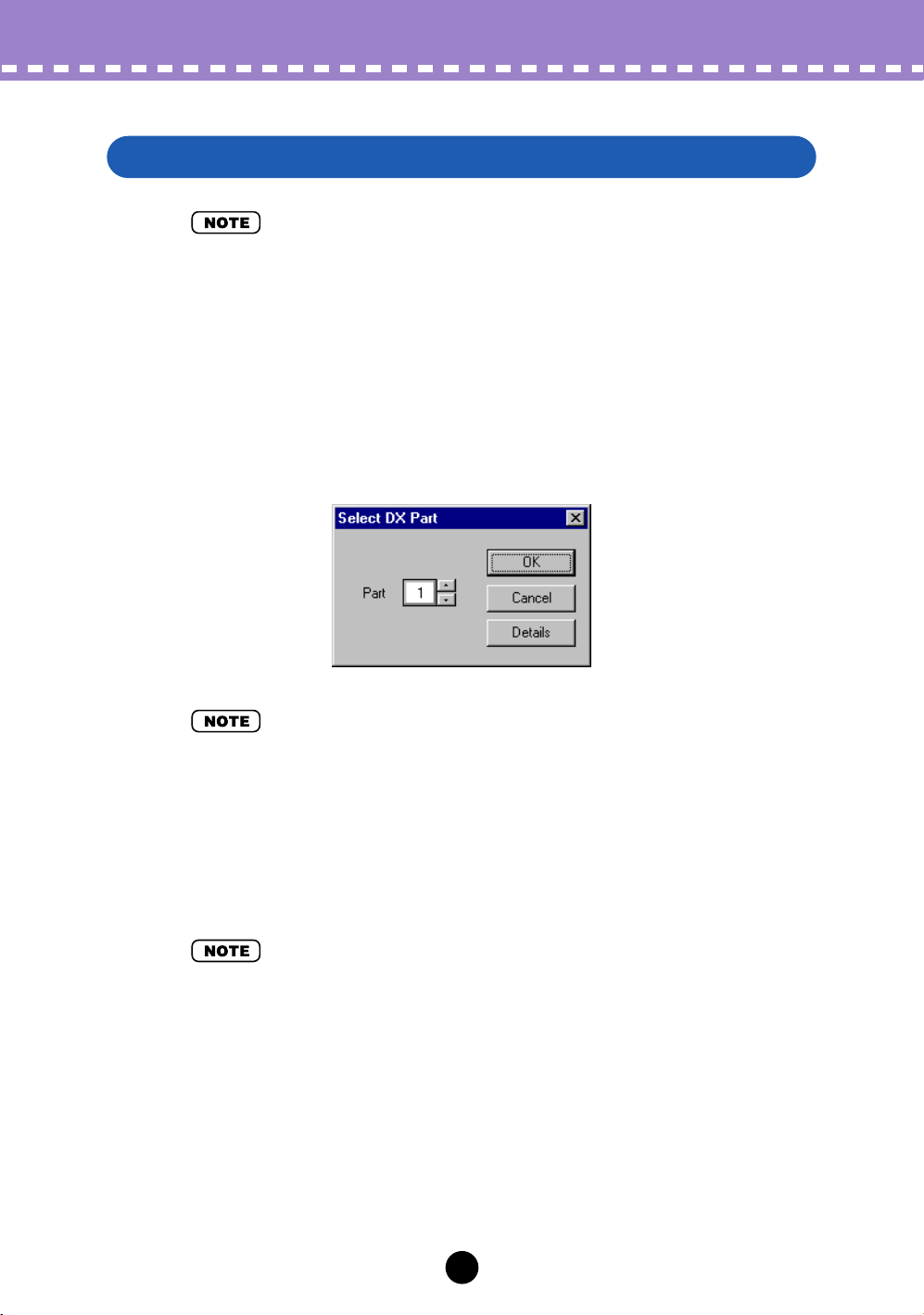
Select DX Part Pop-up Menu
• “Cancel” button may not be available depending on the editor you use.
z
Select the desired Part.
The Select DX Part pop-up menu appears when you first call up the DX Simulator.
Select the desired Part from the Part combo box.
x
Click “OK.”
• Click “Details” to call up the DX Simulator Setup menu for making more detailed settings.
3
Page 4

Operations /
Assigning the PLG150-DX to a Part
DX Simulator Setup
Even after you’ve set the DX Part from the pop-up menu, you can change the setting during an editing session from the DX Simulator Setup dialog box.
z
Select “DX Simulator Setup.”
While the DX Simulator is active and selected, click “Setup” on the menu bar, then
select “DX Simulator Setup.” (Keyboard shortcut: [Alt], [U], [U], then [ENTER].)
• “DX Simulator Setup” can also be selected from the toolbar.
x
Select the desired Part.
Do this from the Part No. combo box in the MIDI tab. Make other settings if necessary. (See DX Simulator Setup.)
c
Click “OK.”
4
Page 5
Operations /
Selecting a DX Voice
Selecting a DX Voice
Selecting a DX voice is the important first step in editing. Once you’ve edited a voice
you can store it to the PLG150-DX or save it to a floppy disk/hard disk drive with other
voices as a DX Cartridge File.
DX voices can be selected from either the Edit Panel window or the Edit List window.
• Only Custom voices can be selected in the DX Simulator.
• Make sure to store your edits to a voice before selecting another voice. If you’ve edited the
DX Simulator parameters and then select a different voice, all your edited parameters will be
replaced by those of the newly selected voice.
Selecting a Voice From the Edit Panel Window
z
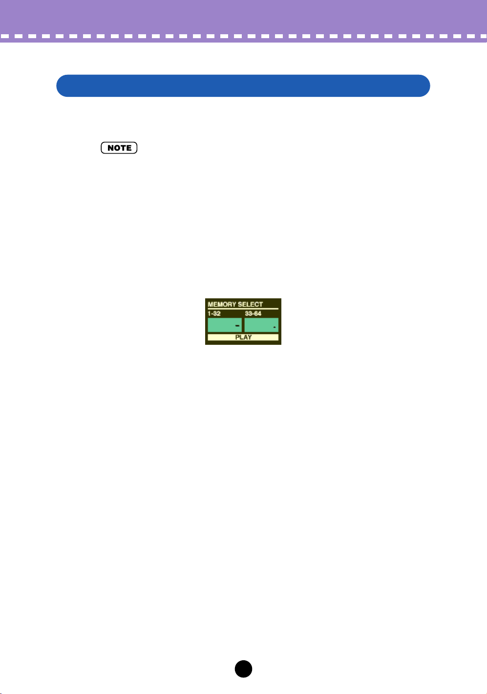
Call up the Play mode.
Click one of the MEMORY SELECT buttons ([1 - 32] or [33 - 64]), depending on the
desired voice number.
x
Click the desired Voice Select button, [1] - [32] or [33] - [64].
The LED displays the voice number, and the LCD displays the voice name and
number.
5
Page 6
Operations /
Selecting a DX Voice
Selecting a Voice From the Edit List Window
z
Select “DX Voice List.”
Click “Edit” on the menu bar, then select “DX Voice List.” (Keyboard shortcut: [Alt],
[E], [V].)
You can also quickly call up this dialog box by right-clicking any inactive part of the
window (on the Macintosh, click while holding the CONTROL key) and clicking “DX
Voice List” in the pop-up menu.
x
Select the desired voice.
Click on the desired voice, then close the dialog box (click the close button) to
return to the Edit List window.
• You can play the currently selected voice by clicking on the keys of the keyboard in the DX
Simulator window.
6
Page 7
Operations /
Opening the Various Windows
Opening the Various Windows
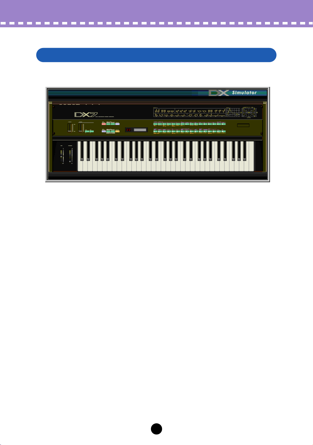
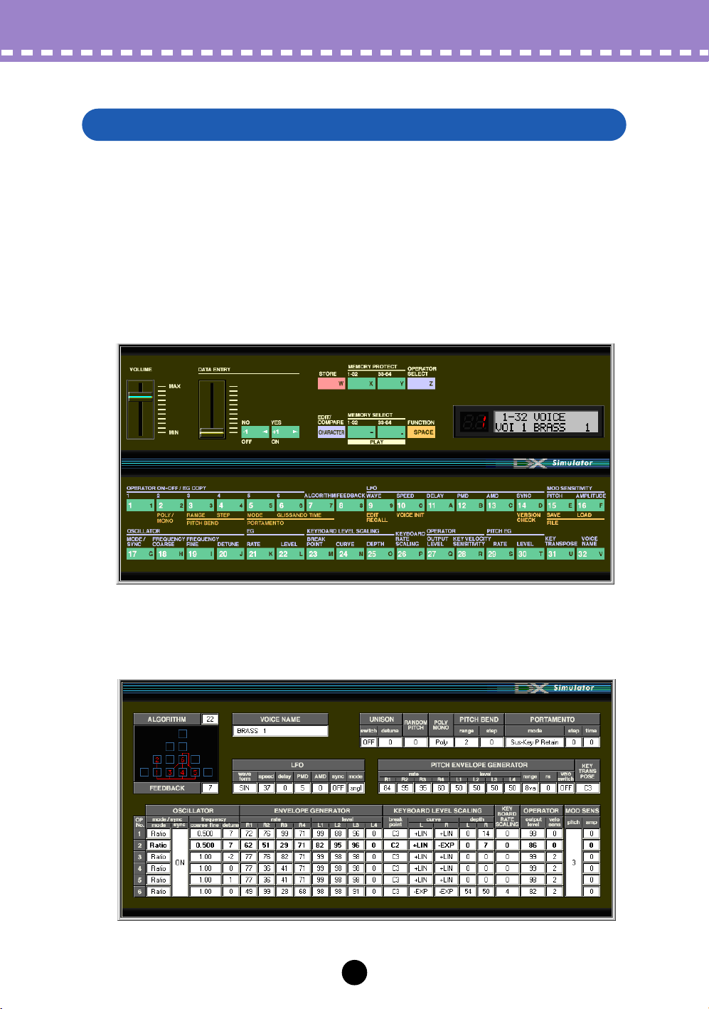
DX Simulator Window
This window automatically appears when you open the DX Simulator and serves as
the “front end” of the plug-in module. For the most part, no editing functions are
available from the DX Simulator window. However, from this window you can:
• Audition the currently selected voice by clicking on the keys of the keyboard.
• Open a DX Cartridge File by clicking on the cartridge or cartridge slot.
• Open the Edit Panel and Edit List windows (below).
Closing the DX Simulator window exits from the DX Simulator plug-in module.
7
Page 8
Operations /
Opening the Various Windows
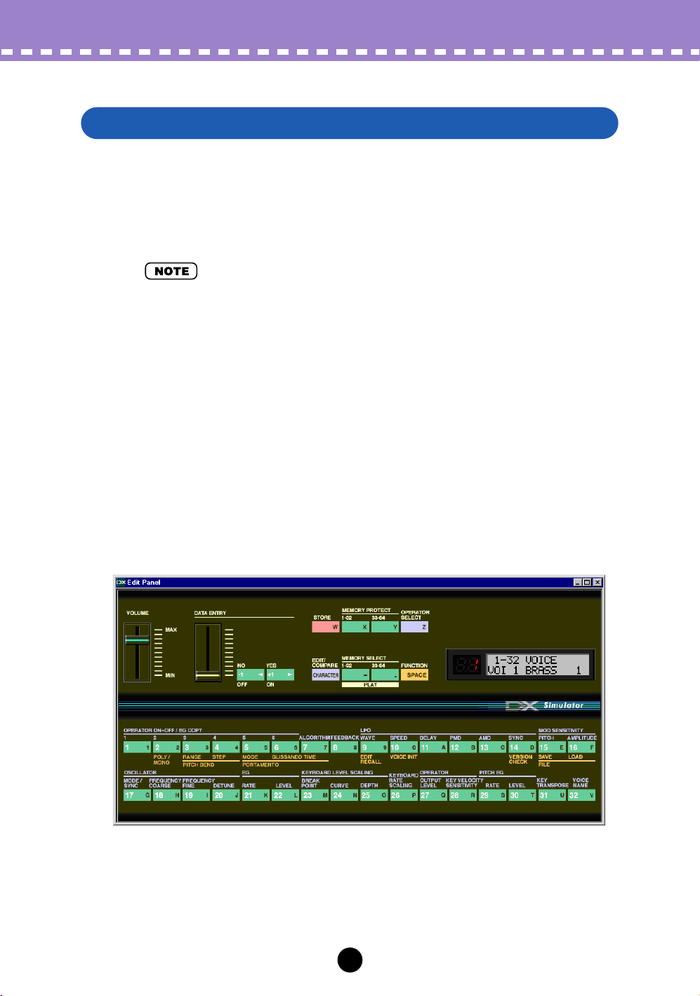
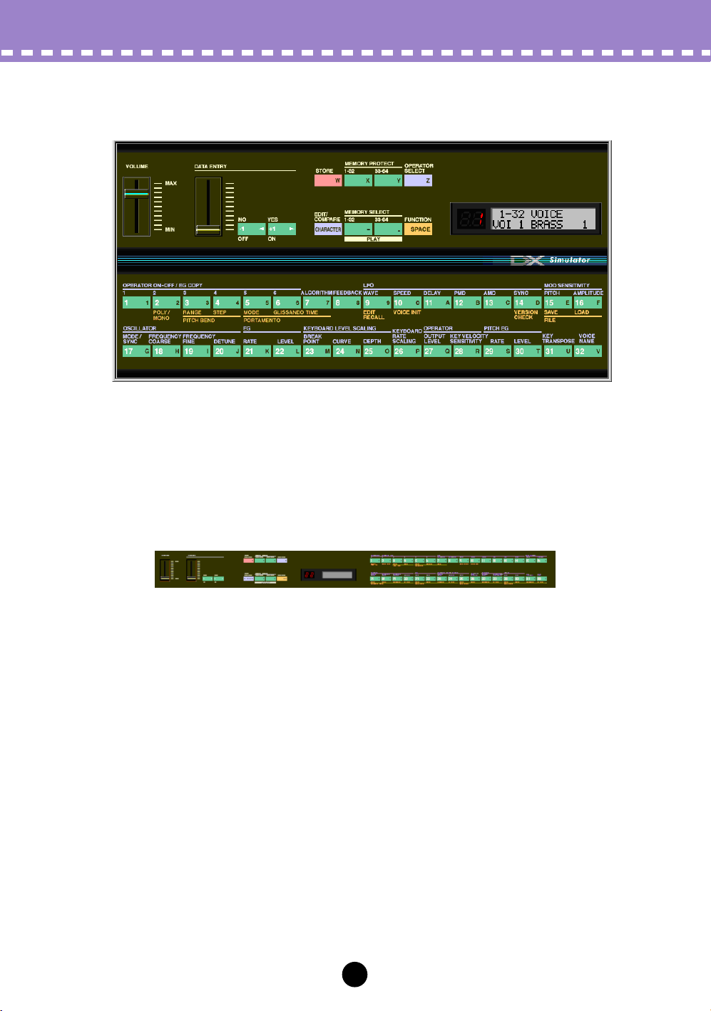
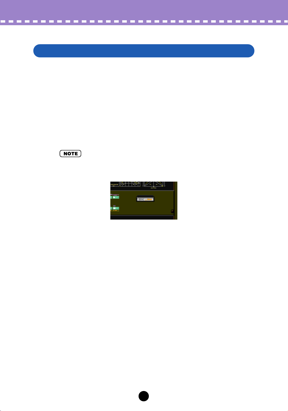
Edit Panel Window
This window provides a “virtual” DX7 panel, and lets you edit the voices much as
you would if you were operating the panel controls of an actual DX7 keyboard. (For
more information, see Editing a DX Voice and DX Simulator Window.)
To call up this window, click anywhere on the panel control area of the DX Simulator
window.
8
Page 9
Operations /
Opening the Various Windows
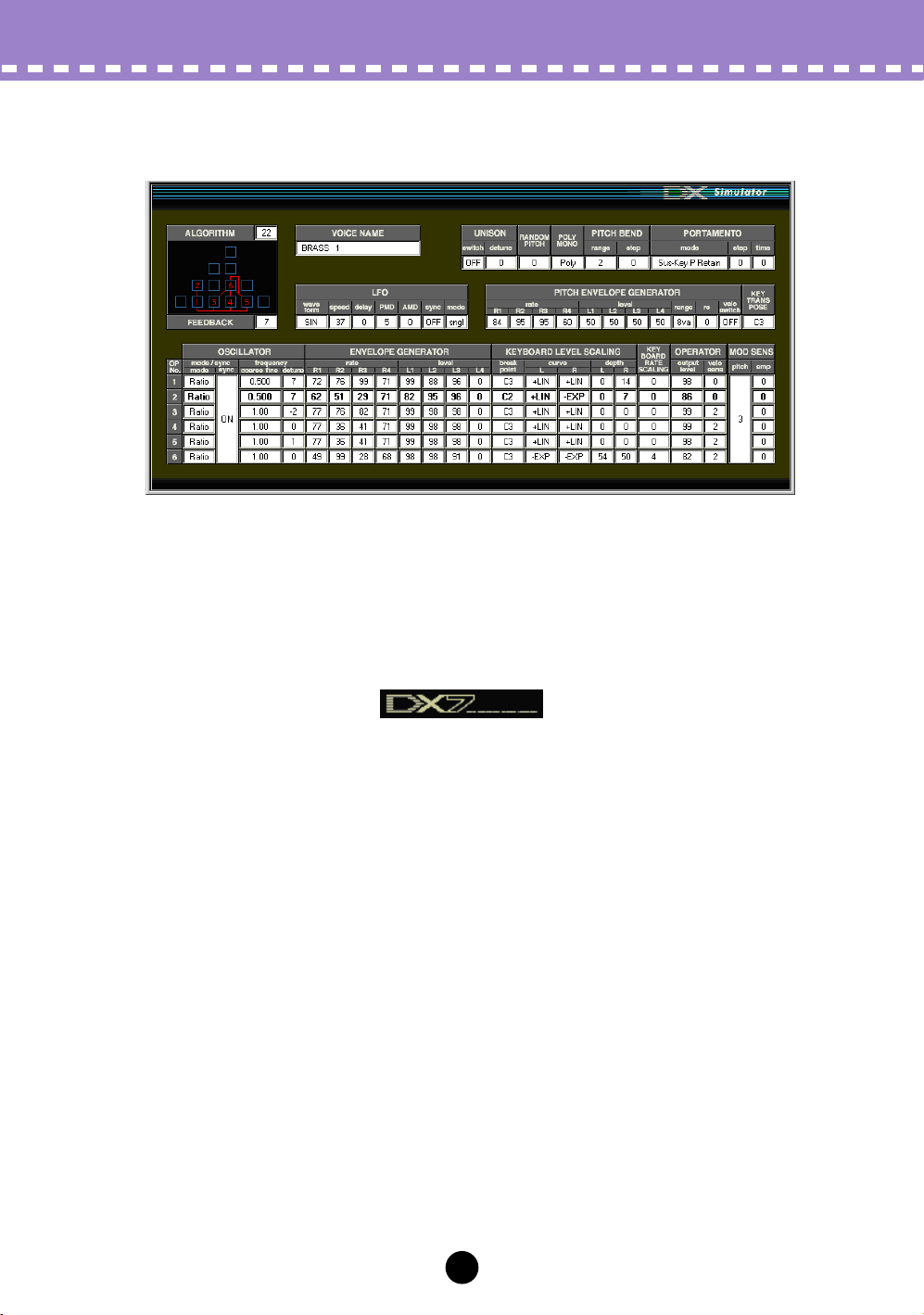
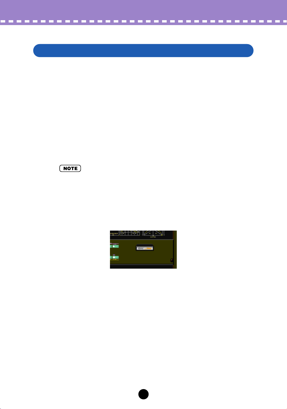
Edit List Window
This window provides a comprehensive, at-a-glance display of all DX voice parameters, and allows you to easily change any desired parameter. (For more information, see Editing a DX Voice.)
To call up this window, click the DX7 logo in the DX Simulator window.
Alternately, click “Edit” on the menu bar, then select “DX Edit List.” (Keyboard shortcut: [Alt], [E], [X].) You can also call it up from the toolbar.
9
Page 10
Operations /
Selecting a Mode — Play, Edit or Function
In the Edit Panel window, you can select from among the three main modes: Play, Edit
and Function.
• Play Mode
In the Play mode, you can:
• Select one of the 64 Custom voices.
• Play the selected voice (from the connected MIDI keyboard or from the keys in the
DX Simulator window).
To select the Play mode:
Click one of the [MEMORY SELECT] buttons: [1-32] or [33-64].
• Edit Mode
In the Edit mode, you can:
• Edit the voice, using the Edit parameters (printed in lavender above each button).
Opening the Various Windows
To select the Edit mode:
Click the [EDIT] button.
• Function Mode
In the Function mode, you can:
• Edit the Function (global) parameters of the voice (printed in yellow below the
appropriate buttons). These include other miscellaneous Function parameters as
well, such as Edit Recall and Voice Initialize.
To select the Function mode:
Click the [FUNCTION] button.
10
Page 11
Operations /
Editing a DX Voice
Editing a DX Voice
z
Select the desired voice.
Refer to Selecting a DX Voice.
x
Edit the voice parameters as desired from one of the editing windows: Edit Panel or Edit List.
The Edit Panel window provides a “virtual” DX7 panel, and lets you edit the voices
much as you would if you were operating the panel controls of an actual DX7 key-
board.
The Edit List window provides a comprehensive, at-a-glance display of all voice
parameters, and allows you to easily change any desired parameter.
11
Page 12

Operations /
c
Store the edited settings as a Custom voice, then save it with
Editing a DX Voice
other edited voices as a DX Cartridge File.
Use the Store operation to store your newly edited voice. Then use the Save operation to save that edited voice with other Custom voices to a DX Cartridge File.
Both the Store and Save operations are necessary to ensure that your voice is
saved properly. Failing to do so would be roughly similar to writing a letter but not
putting it in an envelope. Make sure to execute both operations when you wish to
keep a voice you’ve edited.
12
Page 13
Operations /
Compare
Compare
This function lets you switch back and forth between the current edited condition of the
voice and its original un-edited condition. This allows you to easily hear and compare
the changes you make to a voice with its original condition.
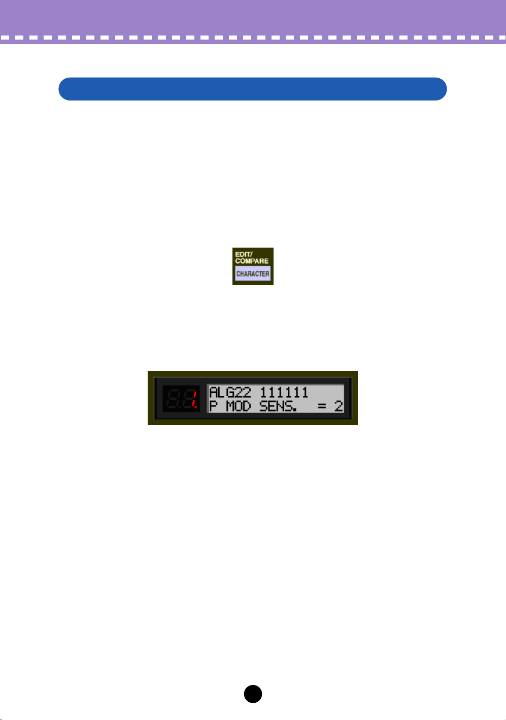
Using Compare From the Edit Panel Window
z
Select the Edit mode.
Click the [EDIT/COMPARE] button.
x
Edit the voice as desired.
As soon as any parameter has been edited, a dot appears at the bottom right of the
voice number in the LED.
c
Select Compare.
Click the [EDIT/COMPARE] button. In the Compare condition, the voice number in
the LED flashes. Play the connected MIDI keyboard (or click the keys in the DX
Simulator window) to hear the original un-edited voice.
While Compare is active, the voice cannot be edited. (Moving the DATA ENTRY
slider has no effect.)
v
Click [EDIT/COMPARE] again to return to the edited condition.
Click the [EDIT/COMPARE] button as often as you wish to go back and forth
between the two conditions.
13
Page 14
Operations /
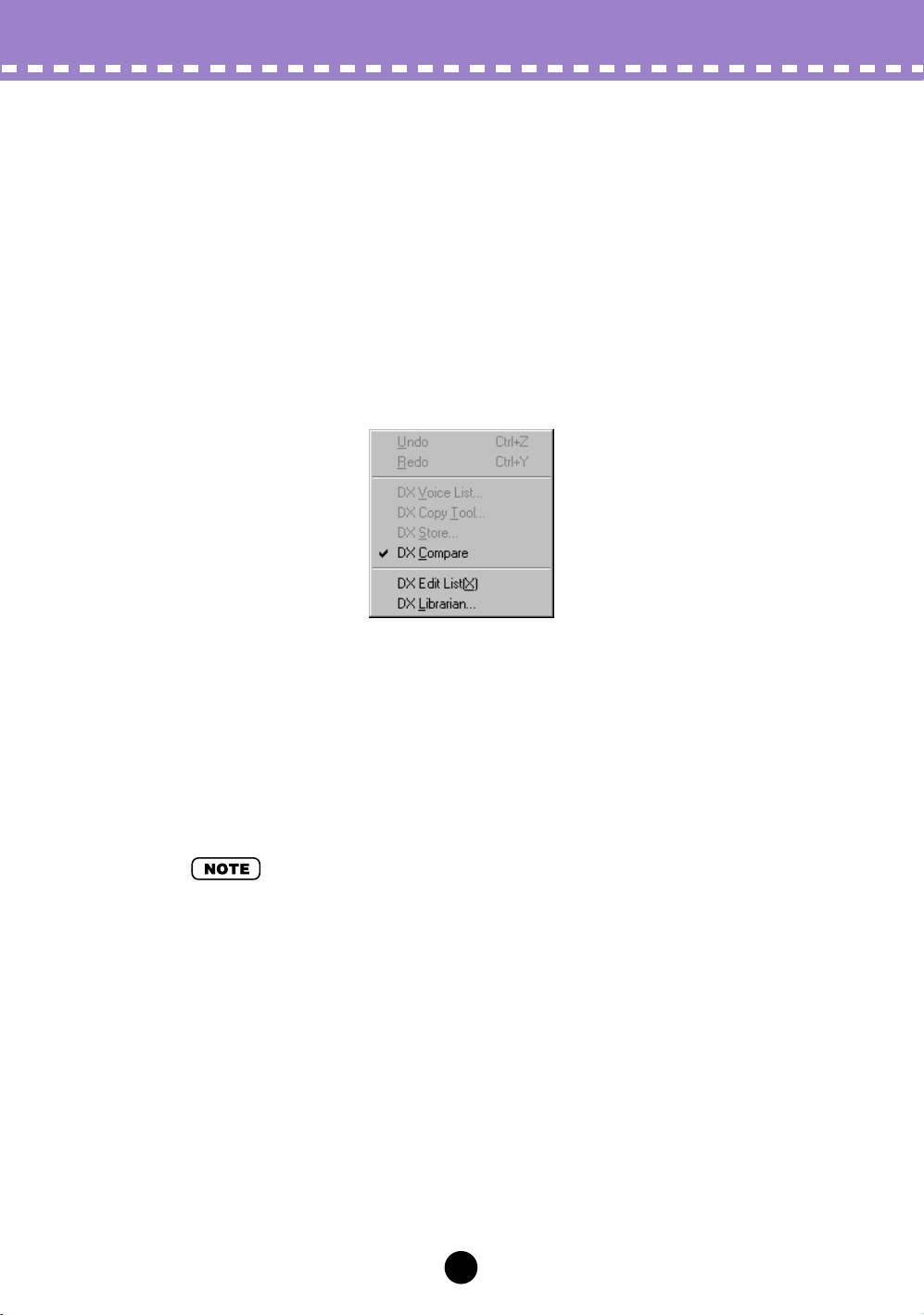
Using Compare From the Edit List Window
z
Edit the voice as desired.
x
Select “DX Compare.”
Click “Edit” on the menu bar, then select “DX Compare.” (Keyboard shortcut: [Alt],
[E], [C].)
You can also quickly use Compare by right-clicking any inactive part of the window
(on the Macintosh, click while holding the CONTROL key) and clicking “DX Compare” in the pop-up menu.
Compare
In the Compare condition, a check appears beside “DX Compare” in the menu. All
parameter values are ghosted and cannot be edited. Play the connected MIDI keyboard (or click the keys in the DX Simulator window) to hear the original un-edited
voice.
c
Select “DX Compare” again to return to the edited condition.
Do this as often as you wish to go back and forth between the two conditions.
• “DX Compare” is ghosted and cannot be selected if the voice has not yet been edited.
14
Page 15

Operations /
Initializing a DX Voice to the Default Settings
Initializing a DX Voice to the Default Settings
This function allows you to reset all the parameters of the selected voice to the factory
“initial voice” default values. This gives you a “blank slate” from which you can create
your own voice.
The currently selected voice can be initialized from either the Edit Panel window or the
Edit List window.
Initializing a Voice From the Edit Panel Window
z
Select the Function mode.
Click the [FUNCTION] button.
x
Initialize the voice.
To do this:
1) Click the [VOICE INIT] button.
2) At the “VOICE INIT?” prompt, click the [YES] button.
3) At the “ARE YOU SURE?” prompt, click [YES] again to actually execute the operation.
Click [NO] to cancel.
15
Page 16
Operations /
Initializing a DX Voice to the Default Settings
Initializing a Voice From the Edit List Window
• Keep in mind that this operation automatically erases all the settings of the selected voice.
z
Select “DX Voice List.”
Click “Edit” on the menu bar, then select “DX Voice List.” (Keyboard shortcut: [Alt],
[E], [V].)
You can also quickly call up this dialog box by right-clicking any inactive part of the
window (on the Macintosh, click while holding the CONTROL key) and clicking “DX
Voice List” in the pop-up menu.
x
Select the desired voice to be initialized.
Click on the desired voice.
c
Initialize the voice.
Click the “Voice Init.” button in the dialog box. The specified voice is initialized and
automatically selected for editing.
16
Page 17
Operations /
Storing a DX Voice
Storing a DX Voice
This operation lets you store your voice edits as a Custom voice. The currently edited
voice can be stored from either the Edit Panel window or the Edit List window.
• To ensure that your new voice is available for future recall, make sure to also save the voice
(with other voices) to a DX Cartridge File.
Storing a Voice From the Edit Panel Window
z
Select the Play mode, and the destination bank (1 - 32, or 33 - 64)
to which the edited voice will be stored.
Click the desired [MEMORY SELECT] button: [1-32] or [33-64]. If necessary, turn
Memory Protect off for the selected bank.
x
Click the [STORE] button.
c
Select the destination voice number to which the edited voice
will be stored.
Click the desired voice select button (1 - 32, or 33 - 64). The specified voice is
replaced with the newly edited voice.
17
Page 18
Operations /
Storing a DX Voice
Storing a Voice From the Edit List Window
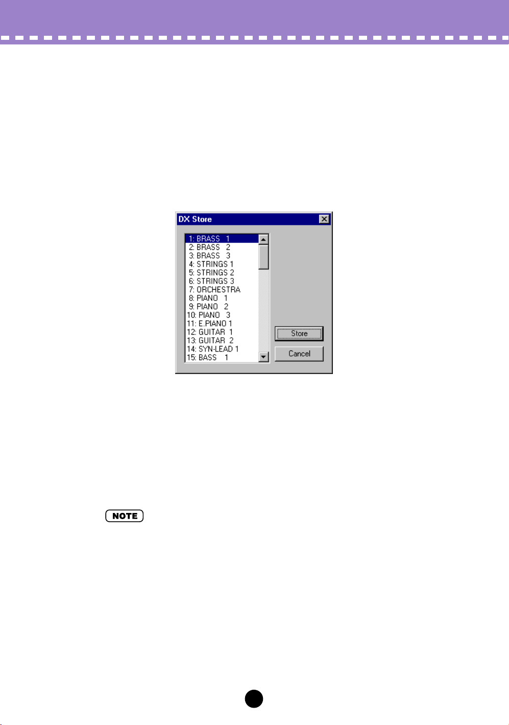
z
Select “DX Store.”
Click “Edit” on the menu bar, then select “DX Store.” (Keyboard shortcut: [Alt], [E],
[S].)
You can also quickly call up this dialog box by right-clicking any inactive part of the
window (on the Macintosh, click while holding the CONTROL key) and clicking “DX
Store” in the pop-up menu.
x
Select the destination voice.
Click on the desired voice in the dialog box.
c
Store the voice.
Click the “Store” button in the dialog box. The specified voice is replaced with the
newly edited voice.
• This operation deletes the original voice data at the destination.
18
Page 19
Operations /
Saving Voices to a DX Cartridge File
Saving Voices to a DX Cartridge File
Once you’ve edited a DX voice to your satisfaction you can save it to a DX Cartridge
File. Each DX Cartridge File can contain up to 64 voices, and these can be called up at
any time with the Open function. (Also see Calling Up Voices from a DX Cartridge File.)
Additional DX Cartridge Files of 64 Custom voices each can be saved to floppy disks or
your hard disk drive as DX Cartridge Files — giving you unlimited storage for your original voices. For organizing the voices in the DX Cartridge Files, use the convenient DX
Librarian function.
z
Select “Save DX Cartridge File.”
Click “File” on the menu bar, then select “Save DX Cartridge File.” (Keyboard shortcut: [Alt], [F], [W].)
• “Save DX Cartridge File” can also be selected from the toolbar.
x
Select the desired folder, type in the file name, and click “Save.”
When a DX Cartridge File has been saved, a cartridge appears in the cartridge slot of
the DX Simulator window.
19
Page 20
Operations /
Calling Up Voices from a DX Cartridge File (Open)
Calling Up Voices from a DX Cartridge File (Open)
Once you’ve saved a set of Custom voices to one or more DX Cartridge Files (see Sav-
ing Voices), you can instantly call up the desired voices with this command.
To create a new DX Cartridge File, use the New DX Cartridge File command.
z Select “Open DX Cartridge File.”
Click “File” on the menu bar, then select “Open DX Cartridge File.” (Keyboard
shortcut: [Alt], [F], [R].)
x Select the desired folder and file name, then click “Open.”
• “Open DX Cartridge File” can also be selected by clicking on the cartridge slot in the DX Simulator window. (When a DX Cartridge File has been opened, a cartridge is shown in the slot.)
20
Page 21
Operations /
Inserting Edited Voice Data to a Track / Extracting Edited Voice Data from a Track
Inserting Edited Voice Data to a Track
• The following information pertains only to the Plug-in Editor.
Custom voice data can be inserted to a host application’s track (using Insert DX Bulk
Dump Data). By inserting appropriate data at appropriate points in the song, you can
have the DX voices change automatically as needed.
z Select “Insert DX Bulk Dump Data” from the Setup menu, or
from the toolbar.
c Set the location (Track, Measure, Beat, and Clock).
x Click “OK.”
Extracting Edited Voice Data from a Track
• The following information pertains only to the Plug-in Editor.
This operation lets you extract Custom voice data contained in a host application’s track
(by using Extract DX Bulk Dump Data).
z Select “Extract DX Bulk Dump Data” from the Setup menu, or
from the toolbar.
c Set the location (Track, Measure, Beat, and Clock).
x Click “OK.”
• By using the Insert and Extract functions together, you can record and recall your edits as
needed — giving you an unlimited amount of “undos.” For each major edit, use Insert to save
the edited condition to a section of a track (inserting each edit to subsequent sections of the
same track). Then, to recall any given edit, use the Extract function and select the appropriate
range of measures.
21
Page 22
Operations /
Receiving Voice Data from a DX7/DX7II
Receiving Voice Data from a DX7/DX7II
This operation lets you transfer voice data from a DX7, DX7II or other DX-compatible
instrument. A single voice or 32 voices can be received. (See Receive DX Bulk Dump
Data).
z Select “Receive DX Bulk Dump Data” from the Setup menu.
x Select the desired Receive Method (“1 Voice” or “32 Voices”).
When “32 Voices” is selected, specify the desired set of voices
(“1 - 32,” or “33 - 64”).
c Click “Start.” The “Start” button changes to “Stop” and the oper-
ation is set to standby (waiting for incoming data).
v Transmit the data from the DX7 or other instrument. (See the
owner’s manual of the instrument for instructions.)
• Make sure that the MIDI connections and settings are appropriate. (This includes the host
application “MIDI In” setting: Setup menu ➔ System Setup dialog box ➔ Device tab ➔ “MIDI
In.”)
b As soon as the DX Simulator starts receiving data, the progress
bar moves, indicating the amount of data received. When the
bar is completely filled, the operation is complete.
To cancel the operation, click “Stop.”
n Click “OK” to exit the operation.
22
Page 23

Parameters
Most of the DX Simulator parameters for editing the DX voices are contained in the
virtual “main control panel” screen. From this main panel, you can also jump to other
windows for controlling additional PLG150-DX functions (such as the EditPanel and
EditList).
Setting and Changing Parameter Values
• The conventions described here pertain primarily to the Edit List Window. For information on
the controls in the Edit Panel window, see Edit Panel Window / Play and Edit Modes.
• Combo boxes
For combo boxes, click the down arrow to expand the box, then highlight the
desired setting.
• Parameter sliders
For parameter sliders, click and hold the slider, then drag as desired. Alternately,
click and hold any position along the slider path; the slider automatically snaps to
the new position.
23
Page 24

Parameters /
• Incrementing/decrementing values
Values and settings in the Edit List window can be changed by clicking on the value
box, and then dragging the cursor up or down, in the direction of the desired
change. To increment or decrement a value, click the right or left mouse button,
respectively. Holding down either mouse button continuously increases or
decreases through the value. The cursor keys on the keyboard can be used to
move around the parameter grid of the Edit List window.
• Typing values directly
Most parameters in the Edit List window can also be set by typing the value directly
in the value box. Click on the box, then type the desired value and press Enter. (To
cancel the type-in value, press Esc.) Once a value box has been selected, you can
also use the left and right mouse buttons as decrement and increment controls,
respectively.
Setting and Changing Parameter Values
• The ENTER and ESC keys have no effect in the Voice Name parameter.
24
Page 25

Parameters / DX Simulator Window
DX Simulator Window
This is the main control panel for the DX Simulator, and is comprised of the virtual
“panel” controls.
• Toolbar
The toolbar gives you quick access to some important functions and controls.
These buttons let you easily execute the desired function without having to select a
menu.
Save DX Cartridge File
This is the same as the corresponding command in the File menu. It lets you save the
current set of Custom voices as a DX Cartridge File for future recall. (See File Menus,
Save DX Cartridge File.)
25
Page 26

Parameters /
DX Simulator Window
DX Simulator Setup
This is the same as the corresponding command in the Setup menu. It lets you make
various important settings for configuring the DX Simulator with the PLG150-DX. (See
Setup Menus, DX Simulator Setup.)
Insert DX Bulk Dump Data (Plug-in Editor only)
This is the same as the corresponding command in the Setup menu. It lets you insert the
current DX Simulator settings to a specified track/position in the host application song.
(See Setup Menus, Insert DX Bulk Dump Data. Also see Inserting Edited Voice to a
Track.)
Extract DX Bulk Dump Data (Plug-in Editor only)
This is the same as the corresponding command in the Setup menu. It lets you import
Part parameter settings in the sequence data to the DX Simulator. (See Setup Menus,
Extract DX Bulk Dump Data. Also see Extracting Edited Voice Data from a Track.)
Transmit DX Bulk Dump Data
This is the same as the corresponding command in the Setup menu. It lets you transmit
the current DX Simulator settings as MIDI data to the PLG150-DX board. (See Setup
Menus, Transmit DX Bulk Dump Data.)
Receive DX Bulk Dump Data
This is the same as the corresponding command in the Setup menu. It lets you receive
the current DX Simulator settings as MIDI data from a DX7, DX7II or other DX-compatible instrument. (See Setup Menus, Receive DX Bulk Dump Data. Also see Receiving
Voice Data from a DX7/DX7II)
Open DX Edit List View
This is the same as the corresponding command in the Edit menu. It lets you call up the
Edit List window for editing a voice. (See Edit Menus, DX Edit List.) You can also call up
the Edit List window by clicking on the DX7 logo in the DX Simulator window.
26
Page 27

Parameters / Edit Panel Window / Play and Edit Modes
Edit Panel Window / Play and Edit Modes
To select the Play mode, click either one of the [MEMORY SELECT] buttons.
To select the Edit mode, click the [EDIT/COMPARE] button.
• Volume slider
This adjusts the overall output level.
• DATA ENTRY slider
This is used for making rapid or large changes. Moving it all the way down and up covers
the full range available for each parameter.
• [NO]/[YES] buttons
These are used to increment or decrement parameter values, to turn a function on or off,
answer display prompts, and to move the cursor when naming a voice.
• [STORE] button
This button calls up the Store operation, for storing the selected voice to the memory of
the PLG150-DX. In the Edit mode, this selects the EG Copy function.
• After you’ve stored a voice to the PLG150-DX, make sure to save the voice to a DX Cartridge
File.
• [MEMORY PROTECT 1-32/33-64] buttons
These buttons let you view and change the MEMORY PROTECT status.
• These are effective only when using the Store operation in the Edit Panel window.
27
Page 28

Parameters /
Edit Panel Window / Play and Edit Modes
• [OPERATOR SELECT] button
This button is used to select the desired operator (1-6) for editing in the Edit mode. Each
successive click of the button steps through the available operators. (If an operator is off,
it will be unavailable.) The operator number is shown at the top right of the LCD for the
appropriate parameters.
Currently selected operator (Operator 6).
Use this button when editing the following Edit parameters:
Amplitude Modulation Sensitivity
Oscillator
Envelope Generator (EG)
Keyboard Level Scaling
Keyboard Rate Scaling
Operator (Output Level and Velocity Sensitivity)
These parameters can all be edited independently for each of the operators.
• [EDIT/COMPARE] button
This button is used to select the Edit mode or the Compare function.
• [MEMORY SELECT 1-32/33-64] buttons
These buttons are used to select the two voice banks of the Custom voices: 1-32 or 33-
64. Clicking either of these buttons also activates the Play mode.
• [FUNCTION] button
This button is used to select the Function mode, which lets you edit certain global parameters of the voice or instrument (printed in yellow below the appropriate voice buttons).
• LED display
The LED window indicates the number of the selected voice. It also indicates whether
the original or edited voice is active when using the Compare function.
• LCD display
The LCD window displays the current status of the PLG150-DX. In the Play mode, it indicates the selected voice bank, and the selected voice name and number. In the Edit and
Function modes, it shows the selected parameter, function, or operation, along with the
relevant value(s) or setting(s).
• Voice Select buttons
In the Play mode, these are used to select voices 1-32 (or 33-64) on the PLG150-DX. In
the Edit mode, the buttons are used to select the Edit parameters (printed in lavender
above the buttons). In the Function mode, they are used to select the Function parameters (printed in yellow below the appropriate buttons).
The following descriptions explain each button’s use in the Edit mode.
28
Page 29

Parameters / Edit Panel Window / Play and Edit Modes
• [1] - [6] OPERATOR ON/OFF-EG COPY (1-6)
These buttons have two functions: 1) to turn individual operators on and off while you are
programming a voice, and 2) to select the operator to which you wish to copy certain
envelope generator (EG) settings.
• [7] ALGORITHM
This button is used to select the Algorithm parameter.
• [8] FEEDBACK
This button is used to select the Feedback parameter.
• [9] - [14] LFO
These buttons are used to select the LFO (Low Frequency Oscillator) parameters.
• [9] WAVE
This is used to select the LFO Waveform parameter.
• [10] SPEED
This is used to select the LFO Speed parameter.
• [11] DELAY
This is used to select the LFO Delay parameter.
• [12] PMD
This is used to select the LFO Pitch Modulation Depth parameter.
• [13] AMD
This is used to select the LFO Amplitude Modulation Depth parameter.
• [14] SYNC
This is used to select the LFO Key Synchronization parameter.
• [15], [16] MOD SENSITIVITY
These buttons are used to select the Modulation Sensitivity parameters.
• [15] PITCH
This is used to select the Pitch Modulation Sensitivity parameter.
• [16] AMPLITUDE
This is used to select the Amplitude Modulation Sensitivity parameter.
• [17] - [20] OSCILLATOR
These buttons are used to select the Oscillator parameters.
29
Page 30

Parameters /
Edit Panel Window / Play and Edit Modes
• [17] MODE/SYNC
These buttons are used to alternately select the Oscillator Mode and Oscillator Sync
parameters.
• [18] FREQUENCY COARSE
This is used to select the Oscillator Frequency Coarse parameter, letting you make large
changes in the current operator’s frequency.
• [19] FREQUENCY FINE
This is used to select the Oscillator Frequency Fine parameter, letting you make small
changes in the current operator’s frequency.
• [20] DETUNE
This is used to select the Oscillator Detune parameter.
• [21], [22] EG
These buttons are used to select the EG Rate 1 - 4 and EG Level 1 - 4 parameters.
• [21] RATE
This is used to select the EG Rate 1 - 4 parameters.
• [22] LEVEL
This is used to select the EG Level 1 - 4 parameters.
• [23] - [25] KEYBOARD LEVEL SCALING
These buttons are used to select the Keyboard Level Scaling parameters.
• [23] BREAK POINT
This is used to select the Keyboard Level Scaling Break Point parameter.
• [24] CURVE
This is used to select the Keyboard Level Scaling Curve parameters.
• [25] DEPTH
This is used to select the Keyboard Level Scaling Depth parameters.
• [26] KEYBOARD RATE SCALING
This is used to select the Keyboard Rate Scaling parameter.
• [27], [28] OPERATOR
These buttons are used to select the Operator parameters.
• [27] OUTPUT LEVEL
This is used to select the Operator Output Level parameter.
30
Page 31

Parameters / Edit Panel Window / Play and Edit Modes
• [28] KEY VELOCITY SENSITIVITY
This is used to select the Operator Velocity Sensitivity parameter.
• [29], [30] PITCH EG
These buttons are used to select the Pitch EG parameters.
• [29] RATE
This is used to select the Pitch EG Rate 1 - 4 and Pitch EG Rate Scaling parameters.
• [30] LEVEL
This is used to select the Pitch EG Level 1 - 4 and Pitch EG Level Range parameters.
• [31] KEY TRANSPOSE
This is used to select the Key Transpose parameter.
• [32] VOICE NAME
This is used to select the Voice Name parameter.
31
Page 32

Parameters /
Edit Panel Window / Function Mode
Edit Panel Window / Function Mode
To select the Function mode, click the [FUNCTION] button.
• [2] POLY/MONO
This is used to select the Poly/Mono parameter.
• [3], [4] PITCH BEND
These buttons are used to select the Pitch Bend parameters.
• [3] RANGE
This is used to select the Pitch Bend Range parameter.
• [4] STEP
This is used to select the Pitch Bend Step parameter.
• [5] - [7] PORTAMENTO
These buttons are used to select the Portamento parameters.
• [5] MODE
This is used to select the Portamento Mode parameter.
• [6] GLISSANDO
This is used to select the Portamento Glissando (Step) parameter.
• [7] TIME
This is used to select the Portamento Time parameter.
• [9] EDIT RECALL
This is used to select the Edit Recall function.
• [10] VOICE INIT
This is used to select the Voice Initialize function.
• [14] VERSION CHECK
This is used to select the Version Check function.
• [15], [16] FILE
These buttons are used to select the File Save and File Load operations.
• [15] SAVE
This is used to select the File Save operation.
• [16] LOAD
This is used to select the File Load operation.
32
Page 33

Edit List Window
Parameters / Edit List Window
To call up this window, click the DX7 logo in the DX Simulator window. Or click “Edit” on
the menu bar, then select “DX Edit List.”
33
Page 34

Algorithm
Range: 1 ... 32
This determines the algorithm used for the voice. The algorithm determines how the
operators are configured for the voice. The FM synthesis system of the PLG150-DX has
32 of these configurations, called “algorithms.” (Refer to the Algorithm List.)
This section displays the signal path, showing which operators are “carriers” and which
are “modulators.” The carriers are in the bottom row of the algorithm and are the actual
sound producers for the voice. Modulators are stacked above the carriers and alter the
timbre or tonal quality of the carriers. A modulator stacked on top of another modulator
alters the timbre even further. Simply put, the carriers produce the sound, and the modulators change the character of the sound.
Parameters /
Parameter Descriptions
Parameter Descriptions
• Changing the algorithm may result in drastic changes to the voice, and could produce unex-
Feedback
Range: 0 ... 7
This determines the level of feedback. Each algorithm provides a feedback operator, in
which the output signal of the operator is looped back to its input. As its name implies,
Feedback produces harsh noise-like harmonics in the voice. The degree of harshness or
amount of noise depends not only on this setting, but also on the level of the feedback
operator and its position in the algorithm.
pectedly loud and noisy sounds.
34
Page 35

Parameters / Parameter Descriptions
Voice Name
This determines the name of the voice being edited. Up to ten characters can be
entered. (In the Edit List window, both uppercase and lowercase letters can be
entered.)
In the Edit List window:
1) Click on the VOICE NAME box.
2) At the cursor position, type the desired name. Up to ten characters (uppercase or
lowercase) can be entered.
3) Store the voice, if desired.
In the Edit Panel window:
1) Click the [EDIT] button to call up the Edit mode.
2) Click the [VOICE NAME] button.
3) Click the [CHARACTER] ([EDIT/COMPARE]) button.
4) Click the [NO]/[YES] buttons to select the cursor position.
5) Click the desired character (printed on the right part of the relevant button).
• Numbers 0 - 9 and letters A - V are selected from the Voice Select buttons.
• Letters W - Z are selected respectively from the STORE, MEMORY PROTECT,
and OPERATOR SELECT buttons.
• Hyphen, period, and space are selected respectively from the MEMORY
SELECT and FUNCTION buttons.
6) Click the [CHARACTER] ([EDIT/COMPARE]) button to exit from the Voice Name
operation.
7) Store the voice, if desired.
35
Page 36

Parameters /
Parameter Descriptions
LFO Parameters
The LFO (Low Frequency Oscillator) parameters are used to regularly modulate the
pitch or volume of a voice, letting you create vibrato, tremolo, or “wah” effects.
These are also related to the Modulation Sensitivity parameters.
• LFO Waveform
Settings:
TRI (triangle)
SAW- (sawtooth down)
SAW (sawtooth up)
SQU (square)
SIN (sine)
S/Hold (sample and hold)
This determines the waveform of the LFO: triangle, sawtooth down, sawtooth up, square,
sine, or sample and hold.
• LFO Speed
Range: 0 ... 99
This determines the speed or frequency of the LFO, with higher values resulting in higher
frequencies (greater speed).
36
Page 37

Parameters / Parameter Descriptions
• LFO Delay
Range: 0 ... 99
This determines the delay time for the LFO, or the amount of time that elapses between
the press of a key and onset of the LFO effect. This is useful in producing delayed vibrato
or tremolo effects (often used by singers or instrumentalists). Higher values result in a
longer delay time.
• LFO PMD (Pitch Modulation Depth)
Range: 0 ... 99
This determines the amount of Pitch Modulation Depth. This sets the degree to which
LFO modulation affects the pitch of the voice, or how widely pitch is modulated by the
LFO. This produces a vibrato effect for the voice. This has no effect if Pitch Modulation
Sensitivity is set to zero.
• LFO AMD (Amplitude Modulation Depth)
Range: 0 ... 99
This determines the amount of Amplitude Modulation Depth. This sets the degree to
which LFO modulation affects the volume of the voice, or how widely volume is modulated by the LFO. When applied to a carrier operator, this produces a tremolo effect;
when applied to a modulator, it produces a “wah” effect. This has no effect if Amplitude
Modulation Sensitivity is set to zero.
• Both Pitch and Amplitude are modulated together by the LFO; LFO cannot be set to modulate
these independently. However, by using the Sensitivity and Depth controls, you can set different degrees of the LFO effect for each.
• LFO Sync (Key Synchronization)
Settings: ON, OFF
This determines whether LFO Key Synchronization is on or off. When Sync is ON, the
LFO is automatically reset to the beginning of the selected waveform each time you play
a note. When sync is OFF, the LFO waveform continues in a “free running” condition;
when you play a note, the result will vary depending on where the LFO is in the cycle.
The effect can be easily detected at low LFO frequencies (i.e., LFO Speed settings below
10).
37
Page 38

Parameters /
Parameter Descriptions
• LFO Mode
Settings: sngl (single), mult (multi)
This determines the operating mode of the LFO; in effect, it determines how many LFOs
are used to modulate the voice (when several notes are played simultaneously).
When set to “sngl,” a single LFO affects all notes played. In other words, the LFO effect
begins when the first key is played, and continues in the same way at the same phase for
all subsequent notes. (This is true when LFO Sync is off; when LFO Sync is on, the
waveform is interrupted and begins anew for each note played.)
When set to “mult,” there are sixteen independent LFOs, one for each of the sixteen polyphonic notes of the PLG150-DX. This means that when you play several notes in sucession, the LFO will affect each note individually, depending on when each note is played.
This creates an exceptionally rich and natural modulation effect for sustained notes in
strings and pad voices, especially when LFO Delay is set to an appropriate value.
• These illustrations show the various LFO conditions for different Sync and Mode settings.
38
Page 39

Parameters / Parameter Descriptions
Modulation Sensitivity Parameters
The Modulation Sensitivity parameters (Pitch and Amplitude) determine the degree
to which LFO modulation affects the voice — in other words, the intensity of the
LFO effect. Modulation Sensitivity is effectively a master control for all modulation
— whether it is automatically applied when the notes are played, or whether it is
applied only by using the “real time” modulation controls on the MIDI keyboard,
such as the Modulation Wheel, Foot Control, Breath Control or After Touch. If the
Pitch or Amplitude Modulation sensitivity is set at zero, then none of the external
controllers can affect the voices.
• Pitch Modulation Sensitivity
Range: 0 ... 7
This determines sensitivity of the voice (all operators) to LFO pitch modulation. Higher
values result in greater sensitivity, or greater intensity of pitch modulation. This parameter setting affects all operators of the voice equally.
• Amplitude Modulation Sensitivity
Range: 0 ... 7
This determines sensitivity of each operator to LFO amplitude (volume) modulation.
Higher values result in greater sensitivity, or greater intensity of volume modulation.
When applied to carrier operators, this produces a tremolo effect. When applied to a
modulator operator, this varies the timbre, producing a “wah” effect.
• These settings may have little or no effect on the sound if the Operator Level is set to a low
value.
39
Page 40

Parameters /
Parameter Descriptions
Oscillator Parameters
The Oscillator parameters give you detailed control over the pitch or frequency of
the individual operators of a voice.
OSCILLATOR MODE/SYNC in the Edit Panel window:
To select the Oscillator Mode and Sync parameters in the Edit Panel window, click
Voice Select button [17] repeatedly. The editor toggles between Mode and Sync each
time you click this button.
• Oscillator Mode
Settings: Ratio, Fixed
This determines whether each operator changes pitch according to the notes playes.
When set to “Ratio” (Frequency Ratio Mode), the corresponding operator tracks the keyboard pitch normally. In other words, playing higher notes on the keyboard results in correspondingly higher frequencies on the operator. When set to “Fixed” (Fixed Pitch
Mode), the keyboard does not affect the operator’s frequency; the operator plays at the
same pitch no matter what key is played.
• The term “oscillator” refers to the frequency or waveform generating element of the operator.
• Oscillator Sync (Key Synchronization)
Settings: ON, OFF
This determines whether Oscillator Key Synchronization is on or off — whether or not the
waveforms of all operators start at the beginning of the wave cycle when a key is
pressed. Note that this affects all operators together.
When Sync is ON, the oscillators are automatically reset to the beginning of their waveforms each time you play a note. When sync is OFF, the waveforms continues in a “free
running” condition; when you play a note, the result will vary depending on where the
waveform is in the cycle. This creates subtle differences in the sound, even when you
play the same note repeatedly. Keep in mind that for certain voices, there may be little or
no audible effect.
40
Page 41

Frequency Coarse/Fine
Range (in Ratio mode): 0.500 ... 61.69
Range (in Fixed mode): 1.000 Hz ... 9772 Hz
This determines the frequency for each individual operator.
In the Edit List window:
Type in the desired value in the appropriate value box or use the mouse to change the
value. When using the mouse, the most efficient method is to click the value box, then
clicking the left/right buttons to decrement/increment the value. Holding down either
button rapidly decreases/increases the value.
In the Edit Panel window:
This parameter is actually divided into two separate but linked parameters: Frequency
Coarse and Frequency Fine. Clicking button [18] (FREQUENCY COARSE) and using
the DATA ENTRY controls lets you make large changes in the current operator’s frequency. Clicking button [19] (FREQUENCY FINE) and using the DATA ENTRY controls lets you make small changes in the current operator’s frequency. Use these in
tandem to set the oscillator’s frequency.
Parameters / Parameter Descriptions
Detune
Range: -7 ... 7
Detune is a “super fine” frequency adjustment for each operator. Mild detuning between
carrier operators can make the overall sound of the voice more full, rich and natural, and
reproduce the subtle pitch differences found in actual acoustic instruments. Maximum
detuning between carriers can be used to produce chorusing effects or simulate an
ensemble of multiple instruments.
Envelope Generator (EG) Parameters
These parameters (eight for each operator) determine how the level of the operator
changes over time. EG applied to a carrier operator changes the volume of the
sound over time, while EG applied to a modulator changes the timbre or the tonal
characteristics.
The four Level parameters determine the levels of the operator at five different
points, and the four Rate parameters determine the amount of time that elapses
between changes of levels. Together, these eight settings give you detailed control
41
Page 42

Parameters /
Parameter Descriptions
over the shape (attack, decay, sustain and release) of the sound, both in volume
and timbre.
The EG Copy function (in the Edit Panel window) and DX Copy Tool (in the Edit List
window) let you easily copy all EG Rate and Level values of one operator to another
operator.
• Rate 1 - 4
Range: 0 ... 99
These determine the amount of time that elapses between changes in the operator level
(as set in Level 1 - 4 below).
• Level 1 - 4
Range: 0 ... 99
These determine the levels of the operator at five points in time. The amount of time that
elapses between these points is set in Rate 1 - 4 above.
• For most normal applications — and especially for carrier operators — the Level 4 parameter
(which determines both the starting and ending level of the operator) should be set to “0.”
Otherwise, the voice will continue to sound indefinitely. Also, Level 1 should be set to an
appropriate value, such as “50” or greater, for proper EG operation.
In the Edit List window:
Type in the desired value in the appropriate value box or use the mouse to change the
value.
In the Edit Panel window:
Click button [21] (EG RATE) repeatedly to call up Rate 1, 2, 3, and 4 in succession.
Likewise, click button [22] (EG LEVEL) repeatedly to call up Level 1, 2, 3, and 4 in succession. Use the DATA ENTRY controls to set the value for each parameter.
42
Page 43

Parameters / Parameter Descriptions
EG Copy
This convenient function (in the Edit Panel window) allows you to easily copy all EG
Rate and Level values of one operator to another operator. (In the Edit List window,
use DX Copy Tool.)
z Select the source operator, by repeatedly clicking the [OPERATOR
SELECT] button.
The currently selected operator number is shown at the top right of the LCD.
x Click the [STORE] button.
c Click the desired [EG COPY] button (1 - 6), corresponding to the num-
ber of the destination operator.
The source operator values are automatically copied to the destination operator.
(The LCD shows the source operator values.)
43
Page 44

Parameters /
Parameter Descriptions
Keyboard Level Scaling Parameters
The Keyboard Level Scaling parameters determine how the Output Level settings
of the operators track the keyboard. In other words, these let you automatically
change the level of individual operators depending on which range of the keyboard
you play. Each operator can be programmed to respond according to any of four
curves on either side of an adjustable break point.
Keyboard Level Scaling can be used to make the tone and/or volume change as
you play in different octaves, for more realistic acoustic instrument simulations.
Extreme settings can also be used for “split keyboard” effects.
The Depth of each curve can also be adjusted.
• Keyboard Level Scaling Break Point
Range: A-1 ... C8
This determines the middle point for the curve. The level is scaled up or down independently on either side of the Break Point in the curve. For most applications and best
results, this should be set somewhere near the middle range of your connected MIDI keyboard (for example, C3).
In the Edit List window:
Type in the desired value in the appropriate value box (MIDI note numbers only; for
example, to select C3, type “60”) or use the mouse to change the value.
44
Page 45

Parameters / Parameter Descriptions
• Keyboard Level Scaling Curve Left (L), Curve Right (R)
Settings:
-LIN (Linear, negative)
-EXP (Exponential, negative)
EXP (Exponential, positive)
LIN (Linear, positive)
These parameters determine the left and right Keyboard Scaling Curves for each of the
operators. Curve Left corresponds to the keys on the keyboard lower than the Break
Point, and Curve Right corresponds to the keys higher than the Break Point. Any one of
the Left Curves can be used with any one of the Right Curves, giving you sixteen different curve variations to choose from.
Negative curves decrease the operator level as you play notes further away from the
Break Point, and positive curves increase the level.
Exponential curves feature a more gradual change in level near the Break Point, and
change the level more drastically the further you play away from the Break Point. Linear
curves provide a “straight line,” proportional relationship between the note played and the
resulting operator level.
• Keyboard Level Scaling Depth Left (L), Depth Right (R)
Range: 0 ... 99
These parameters determine the depth of the selected left or right curve. At a minimum
setting (“0”), there is no scaling, and you can increase (or decrease, for negative curves)
the level up to maximum of “99.”
• For values near the maximum, there has to be some “headroom” — in other words, some
operator output level must be available for increasing. For example, if the Operator Output
Level is set to “90,” and a positive () curve is set, the greatest curve depth that can be
achieved is “9” (the difference between the maximum Output Level and the actual set value).
In this example, while the curve Depth can be set to a value greater than 9, there will be no
more effect than if it were set at 9; if you want more boost as you move up or down the keyboard, then you’ll have to set the operator Output Level at a lower value so that more “headroom” is available for the scaling to boost the level to the maximum of 99.
45
Page 46

Parameters /
Parameter Descriptions
• Keyboard Rate Scaling
Range: 0 ... 7
This determines how the Rate times of the EG respond to keyboard position. In other
words, this lets you automatically speed up or slow down the overall EG time (Rate 1 - 4)
of individual operators depending on which range of the keyboard you play. This parameter controls the degree of scaling; a value of “0” produces no scaling, and higher values
produce a more pronounced scaling effect. For values other than “0,” the higher the note
played, the shorter its overall EG time.
Keyboard Rate Scaling is useful for simulating the natural scaling found on many acoustic instruments — for example, as on an acoustic piano, on which higher notes decay
more quickly than lower notes.
Operator Parameters
These parameters let you set the Output Level and Velocity Sensitivity for each
operator.
• Operator Output Level
Range: 0 ... 99
This determines the level of each operator. The setting made here affects the workings
of many other parameters. For example, Feedback, EG Level 1 - 4, and Velocity Sensi-
tivity may have little or no audible effect if Output Level is set too low. On the other hand,
Keyboard Level Scaling settings may have little or no effect if Output Level is set too high.
When applied to a carrier operator, this affects the volume of the voice; when applied to a
modulator, it affects the timbre.
About Operator On/Off Controls
Each operator can be independently turned on and off during editing — an important
tool in hearing the effects of your edits. For example, you may want to temporarily
mute one carrier operator to better hear the edits you are making on another carrier.
Or you may want to turn an operator alternately on and off to hear how its presence
and absence affects the overall sound.
46
Page 47

Parameters / Parameter Descriptions
In the Edit Panel window:
Click the appropriate [OPERATOR ON/OFF] button (1 - 6) repeatedly to turn the
desired operator on or off.
The numbers in the top row indicate the operators’ on/off status:
“1” for on, “0” for off. In this example, operator 3 is off.
In the Edit List window:
Click the appropriate “OP No.” (Operator Number) button (1 - 6). When an operator is
off, all its parameters are ghosted.
Keep in mind that Operator On/Off is used only temporarily in editing and the on/off status is not saved with the voice. To actually turn an operator off, set its Output Level to “0.”
• Operator Key Velocity Sensitivity
Range: 0 ... 7
This determines the touch sensitivity of an operator, or how its level responds to your
playing strength. When Velocity Sensitivity is set to a value other than “0,” the harder you
play a key, the greater the level of the corresponding operator. The softer you play a key,
the lower the level. When this is set to “0,” the operator level remains the same, no matter
how softly or strongly you play the key. Higher values give you greater dynamic range
between low and high levels. Setting this to an appropriate value for a carrier operator
gives you touch control over volume; setting it for a modulator gives you touch control
over timbre.
47
Page 48

Parameters /
Parameter Descriptions
Pitch Envelope Generator (Pitch EG) Parameters
These parameters (eleven altogether) determine how the pitch of the voice
changes over time. The Pitch EG parameters affect all operators equally.
The four Level parameters determine the pitch of the operator at five different
points, and the four Rate parameters determine the amount of time that elapses
between changes of pitch. Range, Rate Scaling, and Velocity Switch parameters
give you further detailed control over the Pitch EG effect.
Pitch EG can be used to reproduce the subtle pitch changes of acoustic instruments (for example, at the beginning and/or end of a note). At extreme settings, it
also can be used to create unusual special effects.
• A real-time pitch controller, such as the Pitch Bend wheel on a connected MIDI keyboard, can
be used to augment (or cancel) the “automatic” pitch changes made in the Pitch EG parameters.
• Pitch EG Rate 1 - 4
Range: 0 ... 99
These determine the amount of time that elapses between changes in the pitch (as set in
Level 1 - 4 below).
• Pitch EG Level 1 - 4
Range: 0 ... 99
These determine the overall pitch of the voice at five points in time. A value of “50” corresponds to normal pitch, or no pitch change. Values under “50” lower the pitch, and values above “50” raise it. The actual pitch range here depends on the Pitch EG Range
parameter setting. (Higher Pitch EG Range settings result in greater pitch variation.)
The amount of time that elapses between these pitch change points is set in Rate 1 - 4
above.
In the Edit Panel window:
Click button [29] (PITCH EG RATE) repeatedly to call up Rate 1, 2, 3, and 4 in succession. (This includes the Pitch EG Rate Scaling parameter.) Likewise, click button [30]
(PITCH EG LEVEL) repeatedly to call up Level 1, 2, 3, and 4 in succession. (This
includes the Pitch EG Level Range parameter.) Use the DATA ENTRY controls to set
the value for each parameter.
48
Page 49

Parameters / Parameter Descriptions
• Pitch EG Range
Settings:
1/2v (six semitones)
1va (one octave)
2va (two octaves)
8va (eight octaves)
This determines the maximum range of pitch change with the Pitch EG. For example,
when this is set to “1va,” the full range of the Pitch EG Level 1 - 4 parameters is one
octave (six semitones above and below the normal pitch value of “50”). The minimum
setting of “1/2v” lets you create subtle pitch changes, whereas the maximum setting of
“8va” is for extreme pitch variations.
• Pitch EG Rate Scaling
Range: 0 ... 7
This determines how the Rate times of the Pitch EG respond to keyboard position. In
other words, this lets you automatically speed up or slow down the overall Pitch EG time
(Rate 1 - 4) of the voice depending on which range of the keyboard you play. This param-
eter controls the degree of scaling; a value of “0” produces no scaling, and higher values
produce a more pronounced scaling effect. For values other than “0,” the higher the note
played, the shorter its overall Pitch EG time.
Pitch EG Rate Scaling is useful for simulating the natural pitch scaling found on many
acoustic instruments — for example, as on a cello or double bass, for which the beginnings of lower notes may have a slower rise in pitch. It’s also useful for producing
unusual pitch change effects depending on key position.
• Pitch EG Velocity Switch
Settings: ON, OFF
This determines whether Pitch EG intensity is touch sensitive or not. When set to “ON,”
the range of pitch change of the Pitch EG is affected by key velocity. This gives you
exceptionally realistic and expressive control over Pitch EG changes.
49
Page 50

Key Transpose
Range: C1 - C5 (MIDI notes 36 - 84)
This determines the overall pitch (key) transposition setting for the voice. The default
value is C3 (60). Use this control to change the octave setting of a voice, or change it to
a key for ease in playing. For example, to play the voice in the key of C but have it sound
in the key of F, enter a value of F3 or F2 (depending on whether you want to transpose up
or down).
In the Edit List window:
Click KEY TRANSPOSE, then type in the value (36 - 84) and press ENTER on the
computer keyboard. Or use the mouse buttons to increment/decrement the values.
In the Edit Panel window:
1) Click on Voice Select button [31] (KEY TRANSPOSE).
2) Select the DX Simulator window.
3) Click the desired key on the “virtual” keyboard. (The DATA ENTRY controls in the
Edit Panel window cannot be used to change the value.)
4) Return to the Edit Panel window to continue editing or save the voice.
Parameters /
Parameter Descriptions
Unison Parameters
These parameters let you “fatten” up sound of a voice, by grouping together four
detuned “copies” of the voice for every note played.
The PLG150-DX features sixteen-note polyphony, meaning that sixteen notes can
be played simultaneously. In effect, a voice is made up of sixteen sound generating
“elements,” one for each note of polyphony.
The Unison parameters let you reconfigure the element assignment of the PLG150DX such that four elements sound together in unison when you play a single note.
The elements can be detuned from each other by a variable amount, adding
warmth and richness to the sound of the voice.
• The overall polyphony of the PLG150-DX is reduced when Unison is on. Normally, polyphony
is sixteen; when Unison is on, it is four. (Naturally, when Poly/Mono is set to “Mono,” polyphony is fixed at one, no matter what the Unison setting is.)
• These parameters are not available in the Edit Panel window.
• Unison Switch
Settings: ON, OFF
This determines whether the Unison function is on or not. When set to “ON,” four of the
PLG150-DX’s sixteen sound generating “elements” are sounded in unison for each note
played. Keep in mind that this reduces the overall polyphony of the instrument.
50
Page 51

• Unison Detune
Range: 0 … 7
This determines the amount of detuning applied for the Unison function. This setting has
no effect unless Unison Switch is set to “ON.” A value of “0” results in no detuning; higher
values shift the tuning of the four sound generating “elements” further away from each
other, creating a warm, fat sound.
Random Pitch
Range: 0 … 7
This function lets you randomize the overall pitch of the voice for each note you play.
When this is set to “0,” Random Pitch is turned off. Higher values produce greater
amounts of random pitch change for successively played notes.
Poly/Mono
Settings: Poly, Mono
This determines how notes of the voice are allocated. The “Mono” (monophonic) setting
allows only one note to be sounded at a time. This is useful for reproducing “classic” synthesizer lead and bass sounds, and is also ideal for playing parts in which you deliberately want the end of one note to be cut off by the next. The “Poly” setting allows you to
play up to sixteen notes simultaneously.
Parameters / Parameter Descriptions
• Poly/Mono is a Function mode parameter in the Edit Panel window.
51
Page 52

Parameters /
Parameter Descriptions
Pitch Bend Parameters
These parameters determine how the Pitch Bend wheel (on the connected MIDI
keyboard) affects the pitch of the voice.
• The Pitch Bend parameters are Function mode parameters in the Edit Panel window.
• Pitch Bend Range
Range: 0 ... 12 semitones
This determines the maximum amount of pitch change with the Pitch Bend wheel, up or
down. When set to “0,” there is no pitch change. When set to the default of “2,” pitch can
be raised or lowered by a maximum of 2 semitones (1 whole step). The maximum setting
of “12” gives you a full two-octave range (one octave down, one up).
• This parameter is automatically set to “12” and cannot be changed unless Pitch Bend Step
(below) is set to “0.”
• Pitch Bend Step
Range: 0 ... 12 (semitones)
This determines the size of the increments by which the Pitch Bend wheel (on a connected MIDI keyboard) changes the pitch. A setting of “0” results in perfectly smooth
pitch bending. Values other than “0” represent the number of semitones by which the
pitch will “jump” as you move the wheel. For example, the maximum setting of “12” will
cause the wheel to change the pitch in a single, one-octave jump.
• When this parameter is set to a value other than “0,” Pitch Bend Range (above) is automatically set to “12.” (In order to change Pitch Bend Range, this parameter must be set to “0.”)
52
Page 53

Parameters / Parameter Descriptions
Portamento
These three parameters are used to set portamento (glide) and glissando (stepped
glide) effects, and to control certain sustain characteristics of the keyboard. The
particular effects available will change, depending on the Poly/Mono setting of the
voice.
•The Portamento parameters are Function mode parameters in the Edit Panel window.
• Mode
Settings:
In Mono mode:
Fingered Porta
Full Time Porta
In Poly mode:
Sus-Key P Follow
Sus-Key P Retain
When the keyboard is in Mono mode, the available settings are “Fingered Porta” and “Full
Time Porta.” Fingered Portamento is glide that occurs only when you play legato — in
other words, playing successive notes smoothly, not releasing a previously played note
until after the next note is played. Full Time Portamento produces glide from one note to
the next even when you play staccato (releasing one note before playing the next).
When the keyboard is in Poly mode, the available settings are “Sus-Key P Follow” and
“Sus-Key P Retain.” In Sustain-Key Pitch Follow mode, if you play a note or chord and
then play another note or chord, the sustain from the original note/chord glides to the
pitch of the most recently played note/chord. In Sustain-Key Pitch Retain mode, the pitch
of the new note or chord glides from that original pitch(es) without interrupting the sustain
of the original note or chord.
• Glissando (Step)
Settings: OFF, 1 ... 12 (semitones)
When Glissando is set to 1...12, the glide in pitch occurs in discrete semitone steps. This
effect is best heard with a slower rate and when two widely separated notes are played
one after the other. When Glissando is set to “OFF,” normal (continuous) Portamento is
available.
• Time
Range: 0 ... 99
This determines the time of the Portamento or Glissando effects. A setting of “0” produces no effect, while a setting of “99” produces the longest (slowest) pitch changes.
This is contrary to the operation of most PLG150-DX rate controls for which higher values result in faster (shorter) times. In order to turn Portamento or Glissando off, make
sure to set this to “0.”
53
Page 54

Parameters /
Parameter Descriptions
Edit Recall
This Edit Panel window function is used to recall the edited settings of a voice, in
the event you have inadvertently left the editing mode and selected another voice.
z Click [FUNCTION] to enter the Function mode.
x Click [EDIT RECALL].
c Answer the display prompts “EDIT RECALL ?” and “ARE YOU SURE
?” by clicking [YES] twice.
• Edit Recall is available only in the Edit Panel window.
Voice Init (Initialize)
The Voice Initialize function lets you create a “blank slate” starting point for programming a new voice.
z Click [FUNCTION] to enter the Function mode.
x Click [VOICE INIT].
c Answer the display prompts “VOICE INIT ?” and “ARE YOU SURE ?”
by clicking [YES] twice.
The resulting initialized voice has the following settings:
• Algorithm 1
• No modulation
• Operator 1 Output Level set to 99; all other operators off
• “Square” envelopes (EGs)
• All frequency ratios set to 1.00
• Although this operation pertains to the Edit Panel window, a similar Voice Initialize function is
also available in the Edit List window from the DX Voice List dialog box.
54
Page 55

Parameters / Parameter Descriptions
Version Check
This Edit Panel window function is used to check the current version of the DX Simulator software.
z Click [FUNCTION] to enter the Function mode.
x Click [VERSION CHECK].
The current software version is shown in the LCD.
File Operations
These two file-related operations let you Save or Load DX Cartridge File data from
the Edit Panel window.
•SAVE
This lets you save the current set of 64 voices to a DX Cartridge File.
z Click the [FUNCTION] button.
x Click [SAVE] to call up the Save DX Cartridge File dialog box.
(Refer to Save DX Cartridge File for detailed instructions.)
•LOAD
This lets you load (open) a set of 64 Custom voices from an existing DX Cartridge File.
z Click the [FUNCTION] button.
x Click [LOAD].
c Answer the display prompts “64 VOICES LOAD?” and “ARE YOU
SURE?” by clicking [YES] twice.
This calls up the Open DX Cartridge File dialog box.
(Refer to Open DX Cartridge File for detailed instructions.)
55
Page 56

File Menus
When the DX Simulator is active and selected, the following functions appear in the File
menu:
• New DX Cartridge File
• Open DX Cartridge File
• Save DX Cartridge File
• Save DX Cartridge File As
These are used for creating, saving, and opening your original DX Cartridge Files.
Using the Save (or Save As) command here saves all 64 Custom voices to a selected
DX Cartridge File. (The special .DXC extension allows you to easily organize the files.)
By keeping a library of your original voices as DX Cartridge Files, you can easily call up
the settings you need (with the Open command) and quickly insert them to a song or
transmit them to your tone generator/sound card.
• Before saving a set of Custom voices as a DX Cartridge File, make sure to store the voice currently being edited. If a voice is not properly stored, it will not be contained in the DX Cartridge File data.
New DX Cartridge File
Use this function to create a new DX Cartridge File. (Keyboard shortcut: [Alt], [F], [I],
then [ENTER].)
If the currently selected voice has been edited, the display prompts you to store the
voice before opening a new DX Cartridge File. (See Storing a DX Voice.) The new DX
Cartridge File contains the factory preset 64 Custom voices. (These are the same
voices that are automatically loaded when you open the DX Simulator.)
56
Page 57

File Menus / Open DX Cartridge File
Open DX Cartridge File
Use this function to open an existing DX Cartridge File. (Keyboard shortcut: [Alt], [F],
[R], then [ENTER].)
Returns up one level. Creates a new folder.
Selects the desired folder.
Selects the desired
file name.
Lists the file names.
Lists the file names
with details (size,
type, date modified).
Selects the desired
file type.
57
Page 58

File Menus /
Save DX Cartridge File / Save DX Cartridge File As
Save DX Cartridge File / Save DX Cartridge File As
Use these commands to save the current set of Custom voices to a DX Cartridge File.
(The “Save As” command lets you specify a different file name than the original one.)
“Save” keyboard shortcut: [Alt], [F], [W], then [ENTER].
“Save As” keyboard shortcut: [Alt], [F], [M], then [ENTER].
Returns up one level. Creates a new folder.
Selects the desired folder.
Selects the file name.
Type the desired
name here.
• “Save DX Cartridge File” can also be selected from the toolbar.
Selects the desired
file type.
Lists the file names.
Lists the file names
with details (size,
type, date modified).
58
Page 59

Edit Menus
When the DX Simulator is active and selected, the following functions appear in the Edit
menu:
• DX Edit List
• DX Librarian
The following functions are also available from the Edit List window:
• DX Voice List
• DX Copy Tool
• DX Store
• DX Compare
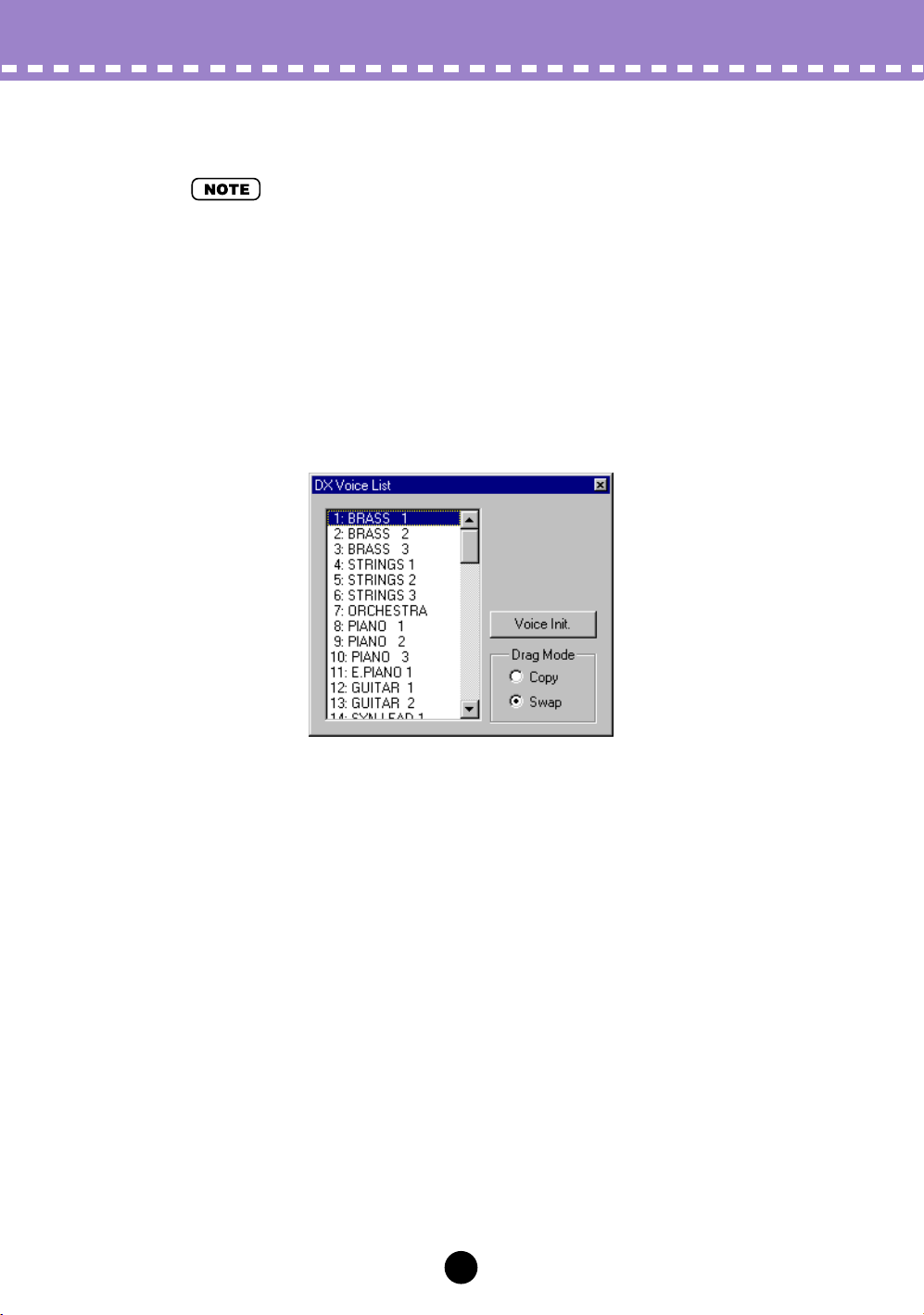
DX Voice List
In the DX Voice List dialog box you can:
• Select a Custom voice for editing.
• Initialize a Custom voice to the default settings.
• Copy or swap voices in the Custom voice banks.
• “DX Voice List” is only available from the Edit List window. It can also be selected from a popup menu by right-clicking on any inactive part of the Edit List window (on the Macintosh, click
while holding the CONTROL key).
59
Page 60

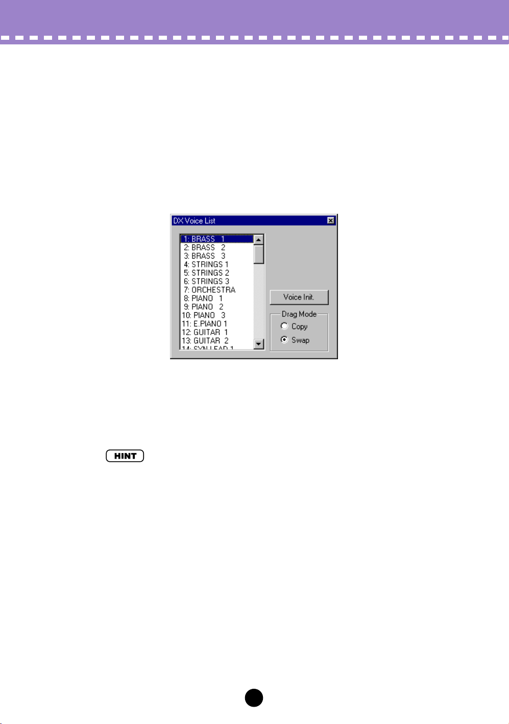
Voice List Box
Select a voice by clicking on the desired voice name in the list.
• Copying a voice to another voice location
z Set Drag Mode to “Copy.”
x Click the desired voice and drag it to the desired location. Keep in
mind that this replaces (and erases) the voice at the location.
• Swapping the location of two voices
z Set Drag Mode to “Swap.”
x Click the desired voice and drag it to voice you wish to swap it with.
This simply moves the voice to the selected location; it does not
affect the actual data.
Copy and Swap operations can also be executed from the DX Librarian dialog box.
Edit Menus /
DX Voice List
Voice Init.
Click this to initialize the selected voice to its default parameter values. This gives you a
“blank slate” from which to create a new voice.
Drag Mode
In the Voice List box, a voice can be dragged to another voice location. This setting
determines the result of that operation: whether the voice is copied to the new location,
or swapped with the voice at the new location.
60
Page 61

Edit Menus / DX Copy Tool
DX Copy Tool
The DX Copy Tool box allows you to quickly copy the parameter values of one operator
to another. You can copy all operator parameter values or just the EG values. This box
also allows you to view the shapes of each operator’s EG and the Pitch EG — giving
you quick, at-a-glance information about all current settings for the EGs.
To select DX Copy Tool:
Click on any of the following title bars in the Edit List window:
• PITCH ENVELOPE GENERATOR
• OSCILLATOR
• ENVELOPE GENERATOR
• KEYBOARD LEVEL SCALING
• KEYBOARD RATE SCALING
• OPERATOR
• MOD SENS
This directly calls up the DX Copy Tool box. It can also be selected from a pop-up menu
by right-clicking on any inactive part of the Edit List window (on the Macintosh, click while
holding the CONTROL key).
• “DX Copy Tool” is only available from the Edit List window. (The menu item is ghosted and
cannot be selected from the DX Simulator window or Edit Panel window.)
To use the Copy Tool:
Click on the desired operator or EG and drag it to the operator/EG to which you wish to
copy. For example, to copy the EG settings of Operator 6 to Operator 2, click on the EG
corresponding to Operator 6 and drag it to the EG corresponding to Operator 2.
The top row of boxes (“OP COPY”) lets you copy all parameter values of one operator to
another. The second row (“EG COPY”) is for copying only EG values of the operators.
The “PITCH EG” box is only for viewing edits made to the Pitch EG parameters.
61
Page 62

Edit Menus /
DX Store
DX Store
Use the DX Store dialog box to store the voice currently being edited to one of the Custom voice memory spaces. Once a voice or voices have been stored in this way, you
can save the entire set of 64 Custom voices to a DX Cartridge File.
• “DX Store” is only available from the Edit List window. It can also be selected from a pop-up
menu by right-clicking on any inactive part of the Edit List window (on the Macintosh, click
while holding the CONTROL key).
z Click the desired location for the newly edited voice.
x Click “Store” to store the voice to the selected location.
Keep in mind that this replaces (and erases) the voice at the location with the newly
edited one.
62
Page 63

Edit Menus / DX Compare
DX Compare
The Compare function lets you switch back and forth between the current edited condition of the voice and its original un-edited condition. This allows you to easily hear and
compare the changes you make to a voice with its original condition.
z Edit the voice.
x Select “DX Compare.”
You can do this from the Edit menu, or with the keyboard shortcut, [Alt], [E], [C].
You can also quickly select Compare by right-clicking any inactive part of the window (on the Macintosh, click while holding the CONTROL key) and clicking “DX
Compare” in the pop-up menu.
In the Compare condition, a check appears beside “DX Compare” in the menu. All
parameter values are ghosted and cannot be edited. Play the connected MIDI keyboard (or click the keys in the DX Simulator window) to hear the original un-edited
voice.
c Select “DX Compare” again to return to the edited condition.
Do this as often as you wish to go back and forth between the two conditions.
• “DX Compare” is ghosted and cannot be selected if the voice has not yet been edited.
• “DX Compare” is only available from the Edit List window. However, an identical Compare
function is available in the Edit Panel window. (See Compare.)
63
Page 64

Edit Menus / DX Edit List / DX Librarian
DX Edit List
Selecting this calls up the Edit List window.
• You can also call up the Edit List window from the toolbar.
DX Librarian
The Librarian dialog box gives you a set of convenient, easy-to-use tools for organizing the Custom voices of your DX Cartridge Files.
The Source box shows Custom voices contained in the opened DX Cartridge File (see
Open Cartridge File below). The Destination box contains the set of Custom voices currently in the DX Simulator, and represents the new DX Cartridge File to be created.
First copy the desired voices from the Source to the Destination, then exit the Librarian
and save the new set of voices as a DX Cartridge File. You can open different DX Cartridge Files one by one, and freely copy the desired voices to the Destination before saving.
64
Page 65

Edit Menus / DX Librarian
Copying a voice from the Source box to the Destination box:
1) Click the desired voice in the Source box. (This is the voice you will be copying.)
2) Drag the highlighted voice to the Destination box, and drop it at the desired number.
(This is the location to which the voice will be copied. The previous voice at the
location is erased and replaced with the new one.)
3) Click “OK” to exit the Librarian.
4) Save the newly created set of Custom voices as a DX Cartridge File.
• Open Cartridge File
Click this to select and open an existing DX Cartridge File. (See Open DX Cartridge
File.) The voices of the opened DX Cartridge File are shown in the Source box.
• Copy All
Clicking this button copies all the voices listed in the Source box to the Destination box.
(This is the same as Open DX Cartridge File.)
• This operation erases all previous voices in the Destination box and replaces them with the
Source voices.
• Init. All
Clicking this button initializes all the Destination voices to their default settings. (See
Initial Voice Default Settings.)
• This operation erases all previous voices in the Destination box and replaces them with identical initialized voices.
•OK
Click this to actually execute any of the Librarian operations and exit from the Librarian
box.
• Cancel
Click this to exit the Librarian box without executing any of the Librarian operations.
65
Page 66

Setup Menus
When the DX Simulator is active and selected, the following functions appear in the
Setup menu:
• DX Simulator Setup
MIDI Tab
Insert & Transmit Tab
• Insert DX Bulk Dump Data (Plug-in Editor only)
• Extract DX Bulk Dump Data (Plug-in Editor only)
• Transmit DX Bulk Dump Data
• Receive DX Bulk Dump Data
• Transmit XG System On
DX Simulator Setup
• “DX Simulator Setup” can also be selected from the toolbar.
•OK
Click this to apply all MIDI tab and Insert & Transmit tab settings.
• Cancel
Click this to exit the DX Simulator dialog box without changing the MIDI tab and Insert &
Transmit tab settings.
MIDI Tab
66
Page 67

Setup Menus / DX Simulator Setup
• MIDI In
Settings: Device, In port number
This determines which MIDI input device (interface) and port is used for transmitting DX
Simulator data.
• MIDI Out
Settings: Device, Out port number
This determines which MIDI output device (interface) and port is used for sending DX
Simulator data. There are four available devices/ports, as specified in the System Setup
parameters (Setup → System Setup). (For details on System Setup, refer to the host
application’s manual.)
• MIDI Channel
Range: 1 ... 16
This determines which MIDI channel is used for sending DX Simulator data. Set this to
match the receive channel for the Part you wish to control.
• Part Number
Range: 1 ... 16
This determines which Part is to be used for the DX voice.
• Device Number
Range: 1 ... 16
This determines which tone generator the DX Simulator will send data to. This should be
set to same number as the Device Number of the tone generator/sound card to which the
PLG150-DX is installed. If you have multiple tone generators in your MIDI setup and
each is set to a different Device Number, this parameter lets you select which tone generator will be affected by the DX Simulator. If you are using only one tone generator, this
should be set to “1.”
• Board Number
Range: 1 ... 8
This determines which tone generator card (or board) the DX Simulator will send data to.
If you have multiple tone generator cards in your MIDI setup and each is set to a different
Board Number (in numerical order from 1), this parameter lets you select which card will
be affected by the DX Simulator. If you are using only one tone generator card, this is
automatically set to “1.”
• Output when edited
When this is checked, any edits that you make with the DX Simulator are instantly and
automatically transmitted to the PLG150-DX. This ensures that you can audition edits as
soon as you make them.
67
Page 68

Setup Menus /
DX Simulator Setup
Insert & Transmit Tab
This tab features various settings related to how the DX data is inserted to the host
application sequence data (using the Insert DX Bulk Dump Data function) or transmitted to the PLG150-DX (using the Transmit DX Bulk Dump Data function).
• Method
1 Voice
When this is selected, only the edited data for one voice will be inserted or transmitted.
• Be careful when using “1 Voice.” If you’ve inserted “1 Voice” (only the edited data) and then
change the voice on the PLG150-DX, you may not be able to revert back to the edited voice.
Use Transmit DX Bulk Dump Data to transmit the desired data to the PLG150-DX.
All Voices
When this is selected, the data for all 64 Custom voices will be inserted or transmitted.
Bulk Dump Interval
This determines the amount of time (in seconds) that separates each “packet” of data
inserted or transmitted. If the tone generator or sound card “chokes” on the incoming
MIDI data, or the insert/transmit operation doesn’t seem to work as expected, try setting the Interval to a higher number.
• Insert Method (Plug-in Editor only)
Create a New Block
When this is selected, a new block (containing the inserted DX bulk dump data) is created to a track in host application.
Insert into a Block
When this is selected, the inserted DX bulk dump data is put into an existing block in
host application.
Interval
This determines the amount of time (in clocks) that separates each insertion. If the
tone generator or sound card “chokes” on the incoming MIDI data, or host application
has trouble sending all the data properly, or the DX voices don't seem to work as
expected, try setting the Interval to a higher number.
68
Page 69

Setup Menus / Insert DX Bulk Dump Data
Insert DX Bulk Dump Data
• The following information pertains only to the Plug-in Editor.
This is used for inserting the edited DX voice data to a song track in host application.
(This is affected also by the DX Simulator Setup settings.) By inserting appropriate data
at appropriate points in a song, you can have the DX voice change automatically as
needed.
• “Insert DX Bulk Dump Data” can also be selected from the toolbar.
• Track
This determines the track to which the DX voice data will be inserted.
• Only tracks that have been set to the “MIDI” type can be selected here.
• Measure / Beat / Clock
This determines the precise location in the track to which the DX voice data will be
inserted. You can specify the Measure (Meas), Beat, and Clock. Make sure to enter this
at the beginning of a song, before any note data.
•OK
Click this to insert the selected DX voice data to the specified location.
• Cancel
Click this to abort the operation.
69
Page 70

Setup Menus /
Extract DX Bulk Dump Data
Extract DX Bulk Dump Data
• The following information pertains only to the Plug-in Editor.
This is used for importing the DX voice data contained in a host application sequence
data to the DX Simulator. Specify the range (Start and End points) from which you want
to extract the data. All current voice data will be replaced by the extracted data. This
function has no effect if there is no DX voice data in the specified range.
• “Extract DX Bulk Dump Data” can also be selected from the toolbar.
• Start
Measure / Beat / Clock
This determines the beginning point in the track from which the DX bulk dump data will
be extracted. You can specify the Measure (Meas), Beat, and Clock.
• End
Measure / Beat / Clock
This determines the end point in the track from which the DX bulk dump data will be
extracted. You can specify the Measure (Meas), Beat, and Clock.
•OK
Click this to extract the data at the specified location.
• Cancel
Click this to abort the operation.
70
Page 71

Setup Menus / Transmit DX Bulk Dump Data
Transmit DX Bulk Dump Data
This is used for directly transmitting the current DX Simulator voice data as MIDI bulk
dump data to the PLG150-DX board. To use this, highlight the command in the menu,
then click.
• “Transmit DX Bulk Dump Data” can also be selected from the toolbar.
71
Page 72

Setup Menus /
Receive DX Bulk Dump Data
Receive DX Bulk Dump Data
This is used for importing DX voice data from a DX7 or DX7II. All current settings will be
replaced by the received data.
• Receive Method
1 Voice
When this is selected, only the data for one voice will be received. This data is loaded
into the edit buffer (temporary memory storage).
• Make sure to store the received voice after executing this operation. Otherwise the data will
be lost upon selecting a different voice.
All Voices
When this is selected, the data for 32 Custom voices will be received. Select the
desired memory bank of voices (1 - 32 or 33 - 64) from the combo box at the right.
• Receive DX Bulk Dump
Start
Click this to start reception of the data. The progress bar indicates how much data has
been received. When the bar is completely filled, all data has been received.
•OK
Click this to exit from the dialog box once all data has been received.
72
Page 73

Setup Menus / Transmit XG System On
Transmit XG System On
This is used for directly transmitting an XG System On message to the tone generator/
sound card, initializing all XG settings. To use this, highlight the command in the menu,
then click.
• This operation initializes all XG parameters (System parameters and Part parameters) and DX
Native Part parameters. On an XG Plug-in System “mother” device, the XG parameters of that
device are also initialized. However, on a Modular Synthesis Plug-in System (MSPS) “mother”
device, the parameters are not initialized.
73
Page 74

Appendix
Appendix /
Initial Voice Default Settings
Initial Voice Default Settings
74
Page 75

Algorithm List
Appendix / Algorithm List
75
Page 76

Appendix /
Algorithm List
76
 Loading...