

Page 1
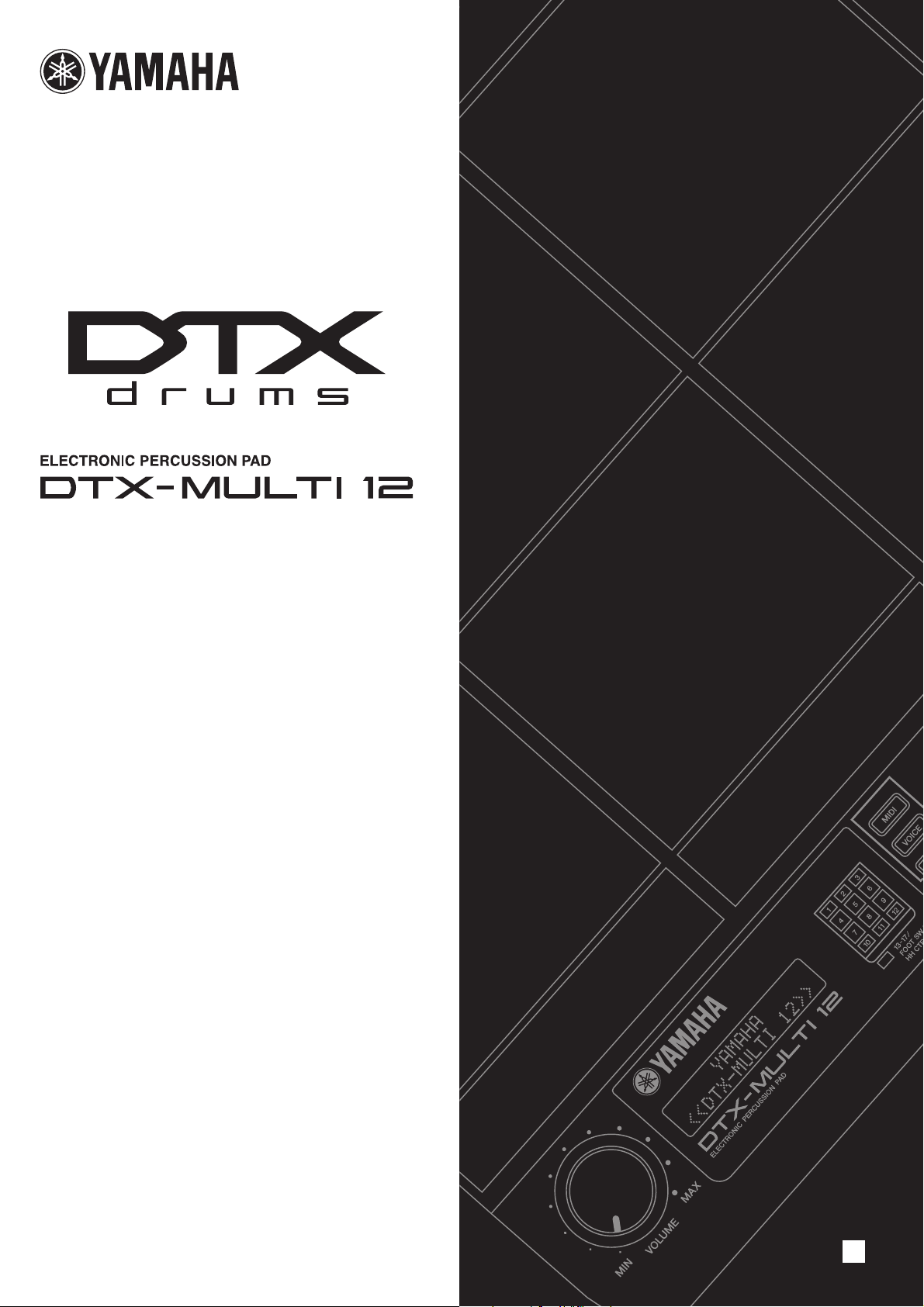
Owner’s Manual
EN
Page 2
SPECIAL MESSAGE SECTION
This product utilizes batteries or an external power supply (adapter). DO
NOT connect this product to any power supply or adapter other than one
described in the manual, on the name plate, or specifically recommended by Yamaha.
WARNING:
walk on, trip over ,or roll anything over power or connecting cords of any
kind. The use of an extension cord is not recommended! If you must use
an extension cord, the minimum wire size for a 25’ cord (or less ) is 18
AWG. NOTE: The smaller the AWG number ,the larger the current handling capacity. For longer extension cords, consult a local electrician.
This product should be used only with the components supplied or; a
cart, rack, or stand that is recommended by Yamaha. If a cart, etc., is
used, please observe all safety markings and instructions that accompany the accessory product.
Do not place this product in a position where anyone could
SPECIFICATIONS SUBJECT TO CHANGE:
The information contained in this manual is believed to be correct at the
time of printing. However, Yamaha reserves the right to change or modify
any of the specifications without notice or obligation to update existing
units.
This product, either alone or in combination with an amplifier and headphones or speaker/s, may be capable of producing sound levels that
could cause permanent hearing loss. DO NOT operate for long periods
of time at a high volume level or at a level that is uncomfortable. If you
experience any hearing loss or ringing in the ears, you should consult an
audiologist.
IMPORTANT: The louder the sound, the shorter the time period before
damage occurs.
Some Yamaha products may have benches and / or accessory mounting fixtures that are either supplied with the product or as optional
accessories. Some of these items are designed to be dealer assembled
or installed. Please make sure that benches are stable and any optional
fixtures (where applicable) are well secured BEFORE using.
Benches supplied by Yamaha are designed for seating only. No other
uses are recommended.
NOTICE:
Service charges incurred due to a lack of knowledge relating to how a
function or effect works (when the unit is operating as designed) are not
covered by the manufacturer’s warranty, and are therefore the owners
responsibility. Please study this manual carefully and consult your dealer
before requesting service.
ENVIRONMENTAL ISSUES:
Yamaha strives to produce products that are both user safe and environmentally friendly. We sincerely believe that our products and the production methods used to produce them, meet these goals. In keeping with
both the letter and the spirit of the law, we want you to be aware of the
following:
Battery Notice:
This product MAY contain a small non-rechargeable battery which (if
applicable) is soldered in place. The average life span of this type of battery is approximately five years. When replacement becomes necessary,
contact a qualified service representative to perform the replacement.
This product may also use “household” type batteries. Some of these
may be rechargeable. Make sure that the battery being charged is a
rechargeable type and that the charger is intended for the battery being
charged.
When installing batteries, do not mix batteries with new, or with batteries
of a different type. Batteries MUST be installed correctly. Mismatches or
incorrect installation may result in overheating and battery case rupture.
Warning:
Do not attempt to disassemble, or incinerate any battery. Keep all batteries away from children. Dispose of used batteries promptly and as regulated by the laws in your area. Note: Check with any retailer of
household type batteries in your area for battery disposal information.
Disposal Notice:
Should this product become damaged beyond repair, or for some reason
its useful life is considered to be at an end, please observe all local,
state, and federal regulations that relate to the disposal of products that
contain lead, batteries, plastics, etc. If your dealer is unable to assist
you, please contact Yamaha directly.
NAME PLATE LOCATION:
The name plate is located on the bottom of the product. The model number, serial number, power requirements, etc., are located on this plate.
You should record the model number, serial number, and the date of purchase in the spaces provided below and retain this manual as a permanent record of your purchase.
Model
Serial No.
Purchase Date
92-BP
2
Owner’s Manual
(bottom)
PLEASE KEEP THIS MANUAL
Page 3
3
FCC INFORMATION (U.S.A.)
1. IMPORTANT NOTICE: DO NOT MODIFY THIS UNIT!
This product, when installed as indicated in the instructions contained in this manual, meets FCC requirements. Modifications not
expressly approved by Yamaha may void your authority, granted by
the FCC, to use the product.
2. IMPORTANT:
or another product use only high quality shielded cables. Cable/s
supplied with this product MUST be used. Follow all installation
instructions. Failure to follow instructions could void your FCC
authorization to use this product in the USA.
3. NOTE:
requirements listed in FCC Regulations, Part 15 for Class “B” digital
devices. Compliance with these requirements provides a reasonable level of assurance that your use of this product in a residential
environment will not result in harmful interference with other electronic devices. This equipment generates/uses radio frequencies
and, if not installed and used according to the instructions found in
the users manual, may cause interference harmful to the operation
of other electronic devices. Compliance with FCC regulations does
* This applies only to products distributed by YAMAHA CORPORATION OF AMERICA. (class B)
When connecting this product to accessories and/
This product has been tested and found to comply with the
not guarantee that interference will not occur in all installations. If
this product is found to be the source of interference, which can be
determined by turning the unit “OFF” and “ON”, please try to eliminate the problem by using one of the following measures:
Relocate either this product or the device that is being affected by
the interference.
Utilize power outlets that are on different branch (circuit breaker or
fuse) circuits or install AC line filter/s.
In the case of radio or TV interference, relocate/reorient the
antenna. If the antenna lead-in is 300 ohm ribbon lead, change the
lead-in to co-axial type cable.
If these corrective measures do not produce satisfactory results,
please contact the local retailer authorized to distribute this type of
product. If you can not locate the appropriate retailer, please contact Yamaha Corporation of America, Electronic Service Division,
6600 Orangethorpe Ave, Buena Park, CA90620
The above statements apply ONLY to those products distributed by
Yamaha Corporation of America or its subsidiaries.
COMPLIANCE INFORMATION STATEMENT
(DECLARATION OF CONFORMITY PROCEDURE)
Responsible Party : Yamaha Corporation of America
Address : 6600 Orangethorpe Ave., Buena Park, Calif. 90620
Telephone : 714-522-9011
Type of Equipment : Electronic Percussion Pad
Model Name : DTXM12
This device complies with Part 15 of the FCC Rules.
Operation is subject to the following two conditions:
1) this device may not cause harmful interference, and
2) this device must accept any interference received including interference
that may cause undesired operation.
See user manual instructions if interference to radio reception is suspected.
* This applies only to products distributed by
YAMAHA CORPORATION OF AMERICA.
Information for Users on Collection and Disposal of Old Equipment
This symbol on the products, packaging, and/or accompanying documents means that used electrical and electronic products should not be
mixed with general household waste.
For proper treatment, recovery and recycling of old products, please take them to applicable collection points, in accordance with your national
legislation and the Directives 2002/96/EC.
By disposing of these products correctly, you will help to save valuable resources and prevent any potential negative effects on human health
and the environment which could otherwise arise from inappropriate waste handling.
For more information about collection and recycling of old products, please contact your local municipality, your waste disposal service or the
point of sale where you purchased the items.
[For business users in the European Union]
If you wish to discard electrical and electronic equipment, please contact your dealer or supplier for further information.
[Information on Disposal in other Countries outside the European Union]
This symbol is only valid in the European Union. If you wish to discard these items, please contact your local authorities or dealer and ask for the
correct method of disposal.
(FCC DoC)
IMPORTANT NOTICE FOR THE UNITED KINGDOM
Connecting the Plug and Cord
IMPORTANT. The wires in this mains lead are coloured in
accordance with the following code:
As the colours of the wires in the mains lead of this apparatus
may not correspond with the coloured makings identifying the
terminals in your plug proceed as follows:
The wire which is coloured BLUE must be connected to the
terminal which is marked with the letter N or coloured BLACK.
The wire which is coloured BROWN must be connected to the
terminal which is marked with the letter L or coloured RED.
Making sure that neither core is connected to the earth terminal of the three pin plug.
• This applies only to products distributed by
Yamaha Music U.K. Ltd.
BLUE : NEUTRAL
BROWN : LIVE
(2 wires)
OBSERVERA!
Apparaten kopplas inte ur växelströmskällan (nätet) så länge som den ar ansluten till vägguttaget,
även om själva apparaten har stängts av.
ADVARSEL:
stikkontakt, som er t endt — også selvom der or slukket på apparatets afbryder.
VAROITUS:
Netspændingen til dette apparat er IKKE afbrudt, sålæenge netledningen siddr i en
Laitteen toisiopiiriin kytketty käyttökytkin ei irroita koko laitetta verkosta.
(standby)
Owner’s Manual
Page 4
PRECAUTIONS
PLEASE READ CAREFULLY BEFORE PROCEEDING
* Please keep this manual in a safe place for future reference.
WARNING
Always follow the basic precautions listed below to avoid the possibility of serious injury or even death from electrical
shock, short-circuiting, damages, fire or other hazards. These precautions include, but are not limited to, the following:
Power supply/AC power adaptor
• Only use the voltage specified as correct for the instrument. The required
voltage is printed on the name plate of the instrument.
• Use the specified adaptor (page 110) only. Using the wrong adaptor can result
in damage to the instrument or overheating.
• Check the electric plug periodically and remove any dirt or dust which may have
accumulated on it.
• Do not place the AC adaptor cord near heat sources such as heaters or radiators,
and do not excessively bend or otherwise damage the cord, place heavy objects
on it, or place it in a position where anyone could walk on, trip over, or roll
anything over it.
Do not open
• Do not open the instrument or attempt to disassemble the internal parts or
modify them in any way. The instrument contains no user-serviceable parts. If it
should appear to be malfunctioning, discontinue use immediately and have it
inspected by qualified Yamaha service personnel.
Water warning
• Do not expose the instrument to rain, use it near water or in damp or wet
conditions, or place containers on it containing liquids which might spill into
any openings. If any liquid such as water seeps into the instrument, turn off the
power immediately and unplug the power cord from the AC outlet. Then have
the instrument inspected by qualified Yamaha service personnel.
• Never insert or remove an electric plug with wet hands.
Fire warning
• Do not put burning items, such as candles, on the unit.
A burning item may fall over and cause a fire.
If you notice any abnormality
• If the AC adaptor cord or plug becomes frayed or damaged, or if there is a
sudden loss of sound during use of the instrument, or if any unusual smells or
smoke should appear to be caused by it, immediately turn off the power switch,
disconnect the adaptor plug from the outlet, and have the instrument inspected
by qualified Yamaha service personnel.
CAUTION
Always follow the basic precautions listed below to avoid the possibility of physical injury to you or others, or damage
to the instrument or other property. These precautions include, but are not limited to, the following:
Power supply/AC power adaptor
• When removing the electric plug from the instrument or an outlet, always hold
the plug itself and not the cord.
• Unplug the AC power adaptor when not using the instrument, or during
electrical storms.
• Do not connect the instrument to an electrical outlet using a multiple-connector.
Doing so can result in lower sound quality, or possibly cause overheating in the
outlet.
Location
• Do not expose the instrument to excessive dust or vibrations, or extreme cold or
heat (such as in direct sunlight, near a heater, or in a car during the day) to
prevent the possibility of panel disfiguration or damage to the internal
components.
• Do not use the instrument in the vicinity of a TV, radio, stereo equipment,
mobile phone, or other electric devices. Otherwise, the instrument, TV, or radio
may generate noise.
• Do not place the instrument in an unstable position where it might accidentally
fall over.
• Before moving the instrument, remove all connected adaptor and other cables.
(3)-13
• When setting up the product, make sure that the AC outlet you are using is
easily accessible. If some trouble or malfunction occurs, immediately turn off
the power switch and disconnect the plug from the outlet. Even when the power
switch is turned off, electricity is still flowing to the product at the minimum
level. When you are not using the product for a long time, make sure to unplug
the power cord from the wall AC outlet.
• Use only the stand/rack specified for the instrument. When attaching the stand
or rack, use the provided screws only. Failure to do so could cause damage to
the internal components or result in the instrument falling over.
• Do not place objects in front of the instrument's air vent, since this may prevent
adequate ventilation of the internal components, and possibly result in the
instrument overheating.
Connections
• Before connecting the instrument to other electronic components, turn off the
power for all components. Before turning the power on or off for all
components, set all volume levels to minimum. Also, be sure to set the volumes
of all components at their minimum levels and gradually raise the volume
controls while playing the instrument to set the desired listening level.
1/2
4
Owner’s Manual
Page 5
5
■
■
Maintenance
• When cleaning the instrument, use a soft, dry cloth. Do not use paint thinners,
solvents, cleaning fluids, or chemical-impregnated wiping cloths.
Saving data
Saving and backing up your data
• Saved data may be lost due to malfunction or incorrect operation. Save
important data to external USB storage device.
Handling caution
• Never insert or drop paper, metallic, or other objects into the gaps on the panel
or keyboard. If this happens, turn off the power immediately and unplug the
power cord from the AC outlet. Then have the instrument inspected by qualified
Yamaha service personnel.
• Do not place vinyl, plastic or rubber objects on the instrument, since this might
discolor the panel or keyboard.
• Do not rest your weight on, or place heavy objects on the instrument, and do not
use excessive force on the buttons, switches or connectors.
• Do not use the instrument/device or headphones for a long period of time at a
high or uncomfortable volume level, since this can cause permanent hearing
loss. If you experience any hearing loss or ringing in the ears, consult a
physician.
Yamaha cannot be held responsible for damage caused by improper use or modifications to the instrument, or data that is lost or destroyed.
Backing up the USB storage device
•To protect against data loss through media damage, we recommend that you
save your important data onto two USB storage devices.
Always turn the power off when the instrument is not in use.
Even when the power switch is in the standby position, electricity is still flowing to the instrument at the minimum level. When you are not using the instrument for a long
time, make sure you unplug the AC power adaptor from the wall AC outlet.
Latest Firmware Version
From time to time, Yamaha may update product firmware without prior notice. We recommend, therefore, that you check our web site (below) for the latest version and
keep your DTX-MULTI 12 firmware up to date.
http://www.yamaha.co.jp/english/product/drums/ed/
The content of this Owner’s Manual applies to the newest version of the firmware as of printing. Details regarding any functions added to later versions will also be made
available via the above web site.
Optional Pads
Within this Owner’s Manual, the optional external pads that may be connected to the DTX-MULTI 12 are referred to by model name. Please note that these model names
were up-to-date as of printing of this manual. Details regarding any subsequently released models will be made available via the following web site.
http://www.yamaha.co.jp/english/product/drums/ed/
Special Notice
• This Owner’s Manual and all content thereof is copyright of Yamaha Corporation.
• The illustrations and LCD screens as shown in this Owner’s Manual are for instructional purposes only and may appear somewhat different from those on your instrument.
• This product incorporates and bundles computer software and other content for which Yamaha retains the copyright or, with respect to which, has license to use others’ copyrights.
Such copyrighted materials include, but are not limited to, all computer software, style files, MIDI data, wave data, musical scores, and sound recordings. Any unauthorized use of
said software and content for non-personal applications is prohibited under applicable laws. Any violation of copyright has legal consequences. DO NOT MAKE, DISTRIBUTE, OR
USE ILLEGAL COPIES.
• This device is capable of using various musical-data types and formats by optimization thereof in advance to a specific proprietary format. As a result, this instrument may not play
back said data exactly as the producers or composers thereof originally intended.
• Copying of commercially available musical data including, but not limited to, MIDI data and/or audio data is strictly prohibited except when intended for personal use.
• The company names and product names in this manual are the trademarks or registered trademarks of their respective companies.
(3)-13
2/2
Owner’s Manual
Page 6
●
●
●
●
Welcome
Thank you for purchasing the Yamaha DTX-MULTI 12 Electronic Percussion Pad.
To get the most out of your new instrument, please read this owner’s manual carefully. And after reading this
document, be sure to store it in a safe place so that you can refer back to it again as needed.
Additional Package Contents
Power adaptor
Owner’s Manual (this document)
Data List booklet
DVD-ROM* (containing software)
* For details on the bundled DVD-ROM, see page 114.
Features of the DTX-MULTI 12
12 built-in pads and versatile input connectors
The DTX-MULTI 12 features 12 built-in pads that have been
conveniently arranged for ease-of-use in a wide variety of performance situations. On the rear panel, furthermore, you will
find input connectors for five additional Yamaha electronic drum
pads and drum triggers. By combining separately-sold pads
and drum triggers with a central DTX-MULTI 12 unit, you can
create your own compact electronic drum kit and also integrate
acoustic drums. Furthermore, with a foot switch jack and a hihat controller jack also included, you can use foot switches and
controllers to select drum kits, to simulate hi-hat playing techniques, and to enhance your performances in a wide range of
other ways.
High-quality sound
In addition to a broad spectrum of voices from the top-of-theline DTXTREME III Drum Trigger Module, the DTX-MULTI 12
also features many newly-sampled percussion sounds and versatile, ready-to-use effect sounds for a grand total of 1,277
voices. What’s more, this rich variety of sounds also includes
timpani, marimba, vibraphone, and many other chromatic percussion instruments. Together with great-sounding Reverb and
Chorus effects that can be applied to entire drum kits, the DTXMULTI 12 also features a Variation effect unit that can be used
to enhance individual voices in many exciting ways.
Wide selection of patterns
The DTX-MULTI 12 comes complete with 128 ready-to-use
melodic and rhythmic phrases (including 3 demos) known as
patterns. You can easily start and stop patterns by simply striking pads to which they are assigned, greatly adding to the
expressiveness of your performances. In addition, you can also
record your own performances as patterns and assign them to
pads in order to conveniently add original grooves to your drum
kits.
Powerful USB expandability
Using the USB TO HOST port and a USB cable (sold separately), the DTX-MULTI 12 can be conveniently connected to a
computer. This affords you a much greater level of efficiency
and speed when recording performances and carrying out
many other music-production processes using computer-based
DAW (digital audio workstation) software such as Cubase AI,
which is bundled with your DTX-MULTI 12.
A USB TO DEVICE port allows USB memory devices to be
plugged in for flexible data exchange. This allows you to store
your DTX-MULTI 12 settings on such a device as standard
computer files; furthermore, you can also import WAV or AIFF
audio files from a USB memory device and assign them to individual pads, thus adding a unique, highly personal flavor to
your performances.
Versatile triggering for enhanced musical possibilities
With the Stack function, each pad can produce up to four different sounds; meanwhile, the Alternate function triggers different
sounds each time a pad is struck. In addition, you can setup
the instrument to automatically select different sounds based
on how hard or soft you strike the corresponding pad or in
response to foot-switch operation.
The DTX-MULTI 12 can also be setup to allow sounds to be
silenced when a hand is pressed down on the pad and to allow
different sounds to be produced when a hand is pressed down
on a pad as it is struck. And you are not restricted to drumsticks
alone! The DTX-MULTI 12 can be easily setup to support a rich
variety of hand playing styles.
6
Owner’s Manual
Page 7
Contents
Additional Package Contents ........................................ 6
Features of the DTX-MULTI 12..................................... 6
Component Names & Functions............................ 8
Setting Up .............................................................. 10
Using with Acoustic Drums .........................................10
Power supply...............................................................10
Connecting Speakers and/or Headphones .................10
Connecting to Other Audio Equipment........................10
Turning on the DTX-MULTI 12.................................... 11
Connecting a USB Memory Device.............................11
Connecting Other MIDI Devices..................................12
Connecting to a Computer .......................................... 13
Making Music with a Computer ................................... 13
Setting up Cubase Remote Control ............................15
Quick Guide
Producing Sounds with the Pads................................. 16
Listening to Patterns ..................................................... 20
Making Your Own Patterns ........................................... 21
Saving Your Data on a USB Memory Device............... 23
Importing Audio Files.................................................... 25
Reference
Internal Design ...................................................... 27
Functional Blocks ........................................................ 27
Pads & Trigger Signals ...............................................28
Sounds Produced Using the Pads ..............................31
Kit Makeup .................................................................. 32
Effects ......................................................................... 36
Internal Memory .......................................................... 42
Basic Operations .................................................. 44
KIT Setting Area (KIT)........................................... 46
Makeup of KIT Setting Area ........................................ 46
KIT1 Select Kit ............................................................47
KIT2 Kit Volume, Tempo & Name ............................... 47
KIT3 Effect Send Levels..............................................48
KIT4 Variation Effect Setup......................................... 48
KIT5 Chorus Effect Setup ...........................................49
KIT6 Reverb Effect Setup ...........................................50
KIT7 Other Drum Kit Settings......................................51
KIT8 Kit Management .................................................53
MIDI Setting Area (MIDI) ....................................... 61
Structure of MIDI Setting Area ....................................61
MIDI1 Select Message Type .......................................62
MIDI2 MIDI Destination Switches................................66
MIDI3 Other MIDI Settings ..........................................67
WAVE Setting Area
Makeup of WAVE Setting Area ...................................69
WAVE1 Wave Selection & Playback...........................70
WAVE2 Playback Mode, Trim Points & Name ............70
WAVE3 Other Wave-Related Tasks ...........................71
WAVE4 Wave Memory Status ....................................73
(WAVE) ................................ 69
PATTERN Setting Area (PTN) .............................. 74
Makeup of PATTERN Setting Area .............................74
PTN1 Select Pattern....................................................75
PTN2 Looping, Tempo & Pattern Names....................75
PTN3 MIDI Settings for Patterns .................................76
PTN4 Pattern Quantization & Management ................78
PTN5 Pattern Memory Status .....................................81
UTILITY Setting Area (UTIL)................................. 82
Makeup of UTILITY Setting Area ................................82
UTIL1 System Settings................................................83
UTIL2 Click Track Settings..........................................84
UTIL3 Master Equalization ..........................................86
UTIL4 Pad Utilities.......................................................88
UTIL5 Hi-hat Setup......................................................89
UTIL6 Instrument MIDI Setup......................................90
UTIL7 File Management..............................................92
UTIL8 Instrument Reset ..............................................98
TRIGGER Setting Area (TRG) .............................. 99
Makeup of TRIGGER Setting Area .............................99
TRG1 Select Trigger Setup .......................................100
TRG2 Pad Setup .......................................................100
TRG3 Trigger Setup Names......................................104
TRG4 Copy Trigger Parameters ...............................104
Troubleshooting ................................................. 105
On-screen Messages.......................................... 108
Specifications ..................................................... 110
Index .................................................................... 111
About the accessory disk .................................. 114
SOFTWARE LICENSE AGREEMENT................. 114
VOICE Setting Area
Makeup of VOICE Setting Area ..................................55
VCE1 Select Voice...................................................... 56
VCE2 Voice Tuning, Volume & Pan............................ 57
VCE3 Voice Timbre.....................................................58
VCE4 Effect Send Levels............................................ 59
VCE5 Other Voice-Related Settings ........................... 60
(VCE).................................... 55
Owner’s Manual
7
Page 8
Component Names & Functions
■
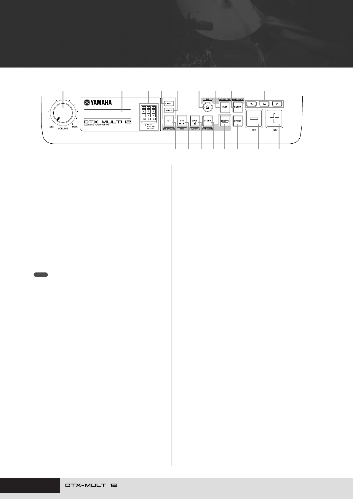
Front Panel
e !5
r !1 !2 !3tqw
≤≤≤≤≤YAMAHA
<<DTX-MULTI≤12>>
o !0 !4 !6 !7iuy
q
w
e
r
t
y
u
i
o
!0
!1
!2
!3
!4
VOLUME Dial
This dial controls the master volume (i.e., the volume at the
OUTPUT jacks). Turn the dial clockwise to increase the volume
or counter-clockwise to decrease it.
Display
This LCD screen shows information and data needed for operation.
Pad Indicator
This array of LEDs shows the pads that have been struck and
are currently producing a sound. The displayed numbers 1 to
12 correspond to the twelve main and rim pads on the instrument itself. In addition, the lamp [13-17] turns on in response to
playing of expansion pads (sold-separately), which are connected via the PAD jacks on the rear panel, or to signals from a
foot switch or hi-hat controller (sold-separately), which is connected via the FOOT SW or HI-HAT CONTROL jack, also on
the rear panel.
NOTE
• Before use, be sure to remove the transparent film applied to the indi-
cator panel to protect it during transportation.
[MIDI] Button
This button is used to access the MIDI setting area (see page
61). In addition, you can turn on and off the Cubase Remote
function by holding down the [SHIFT] button and pressing the
[MIDI] button. When this function is turned on, the buttons on
the DTX-MULTI 12 front panel can be used to control Cubase
operations (see page 15).
[VOICE] Button
This button is used to access the Voice setting area (see page
55).
[KIT] Button
This button is used to access the Kit setting area (see page
46). In addition, you can toggle effects applied to the current
drum kit on and off by holding down the [SHIFT] button and
pressing the [KIT] button (see page 83).
[PTN] Button
The Pattern button is used to access the Pattern setting area
(see page 74). In addition, you can also activate Record Mode
by holding down the [SHIFT] button and pressing the [PTN]
button (see page 21).
[WAVE] Button
This button is used to access the Wave setting area (see page
69). In addition, you can also open the Import page by holding
down the [SHIFT] button and pressing the [WAVE] button (see
page 25).
[UTILITY] Button
This button is used to access the Utility setting area (see page
82). In addition, you can also access the Trigger setting area by
holding down the [SHIFT] button and pressing the [UTILITY]
button (see page 99).
[SHIFT] Button
Hold down this button and press another button to access the
setting area or function indicated above or below it.
EE
[EE
] Button
The Click-track button is used to start and stop the built-in clicktrack (or metronome). In addition, you can also activate the Tap
Tempo function by holding down the [SHIFT] button and pressing
the [ ] button.
E
[EXIT] Button
The parameter-setting pages in each setting area are arranged
in a hierarchical structure. Press this button to leave the current
page and move one step back towards the top of the setting
area. In addition, you can instantly turn off all sound by holding
down the [SHIFT] button and pressing the [EXIT] button.
[ENTER] Button
This button is used to execute processes and confirm values. In
addition, you can activate the Panel Lock function to lock and
unlock the front panel by holding down the [SHIFT] button and
pressing the [ENTER] button. In this way, the front panel can be
deactivated during performances in order to avoid making unintentional changes to settings. Even with the Panel Lock activated, the [KIT] and [VOICE] buttons can be used to access the
corresponding setting areas; however, you will only be able to
change the current kit using the [-/DEC] and [+/INC] buttons or
visually confirm the voice assigned to struck pads. To check
voices with the Panel Lock activated, press the [VOICE] button.
[STORE] Button
This button is used to store settings and other data in the DTXMULTI 12’s internal memory. In addition, this button will light up
whenever parameters have been changed but not yet stored.
!5 [B] [D] [C] Buttons
• These selector buttons are used to navigate between parameter-setting pages and parameters in the various setting
areas.
•You can activate and deactivate Input Lock mode by holding
down the [SHIFT] button and pressing the [D] button (see
page 103).
•With a parameter-setting page displayed, you can move to the
first parameter-setting page of the previous or next parameter
section in the current setting area by holding down the
[SHIFT] button and pressing the [B] or [C] button.
8
Owner’s Manual
Page 9
Component Names & Functions
FF
FF
!6 [-/DEC] Button
This button is used when setting parameters to decrease the
value at the cursor position. In addition, the selected value can
be decreased in units of 10 by holding down the [SHIFT] button
and pressing the [-/DEC] button or by holding down the [-/DEC]
button and pressing the [+/INC] button.
■ Side Panel
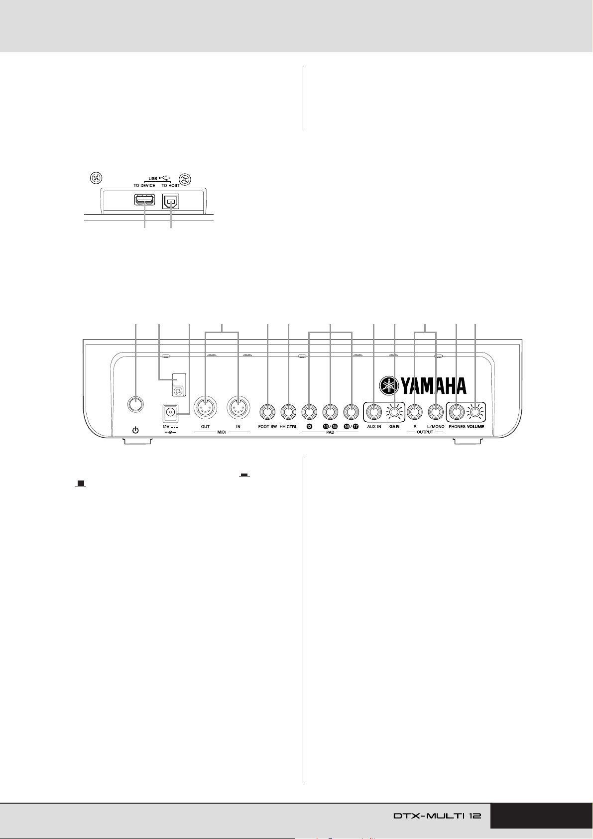
USB TO DEVICE Port
!8
This port is used to plug in a USB memory device (such as a flash drive or external
hard disk), either directly or via a USB cable. When connected in this way, you will be
able to save data created on the DTX-MULTI 12 to the USB memory device and to
import settings, sound files, and the like.
!8 !9
!9 USB TO HOST Port
This port is used to connect the DTX-MULTI 12 to a computer via a USB cable. When
connected in this way, you will be able to exchange MIDI data between the instrument
and your computer.
■ Rear Panel
@3 @9@6@4@0 @5 @7 @8 #0 #1@1 @2
!7 [+/INC] Button
This button is used when setting parameters to increase the
value at the cursor position. In addition, the selected value can
be increased in units of 10 by holding down the [SHIFT] button
and pressing the [+/INC] button or by holding down the [+/INC]
button and pressing the [-/DEC] button.
@0 Standby/On Switch
Use this switch to turn your DTX-MULTI 12 on ( ) and off
().
@1 Cord Clip
Wrap the cord from the power adaptor around this clip to prevent accidental unplugging during use.
@2 DC IN Terminal
Connect the power cord from the power adaptor (provided) to
this terminal.
@3 MIDI IN/OUT Connectors
The MIDI IN connector is used to receive control or performance data from another MIDI device, such as an external
sequencer, via a MIDI cable. When connected in this way, you
can play the internal tone generator and control a wide range of
parameters using another MIDI device. Meanwhile, the MIDI
OUT connector is used to send performance data from this
instrument to other devices in the form of MIDI messages.
@4 FOOT SW Jack
The Foot Switch jack is used to connect an optional foot switch
(FC4, FC5, FC7, etc.) or hi-hat controller (HH65, etc.) to the
DTX-MULTI 12.
@5 HI-HAT CONTROL Jack
The Hi-hat Control jack is used to connect an optional hi-hat
controller (HH65, etc.).
@6 PAD Jacks (!3 to !7)
These trigger-input jacks are used to connect optional pads.
The PAD !3 jack is compatible both with mono and stereo (two-
and three-zone) types; meanwhile, the PAD !4/!5 and the PAD
!6/!7 jacks support standard mono-output pads (see page 30).
@7 AUX IN Jack
External audio signals can be input via this standard stereophone plug. In this way, you can connect an MP3 or CD player
to play along with your favorite tunes.
@8 GAIN Knob
Use this knob to adjust the gain level for audio being input via
the AUX IN jack. This adjustment may be necessary given that
external audio devices output signals at a wide range of different volumes. Increase the gain by rotating the knob clockwise,
and decrease it by rotating the knob counter-clockwise.
@9 OUTPUT L/MONO and R Jacks
Use these jacks to output line-level stereo mixes. For example,
you can connect each of the jacks to the left and right inputs of
an external stereo amplifier or mixer using mono audio-jack
cables. For mono output, use the L/MONO jack only.
#0 PHONES Jack
Use this standard audio jack to connect a pair of stereo headphones.
#1 VOLUME Knob
Use this knob to adjust the level of audio output from the
PHONES jack. Increase the volume by rotating the knob clockwise, and decrease it by rotating the knob counter-clockwise.
Owner’s Manual 9
Page 10
Setting Up
FF
FF
F
Using with Acoustic Drums
If you intend to use your DTX-MULTI 12 together with a set of
acoustic drums, you can attach an MAT1 Module Attachment
(sold separately) to the bottom of the unit so that it can be conveniently assembled to a tom holder or a stand. For details regarding
assembly, refer to the owner’s manual that comes with the MAT1.
Power supply
Ensure that the (Standby/On) switch on the
1
rear panel is turned off.
Connect the DC power cord from the power adap-
2
tor (included) to the DC IN terminal on the rear
panel. To prevent the cord from being accidentally unplugged, wrap it around the cord clip.
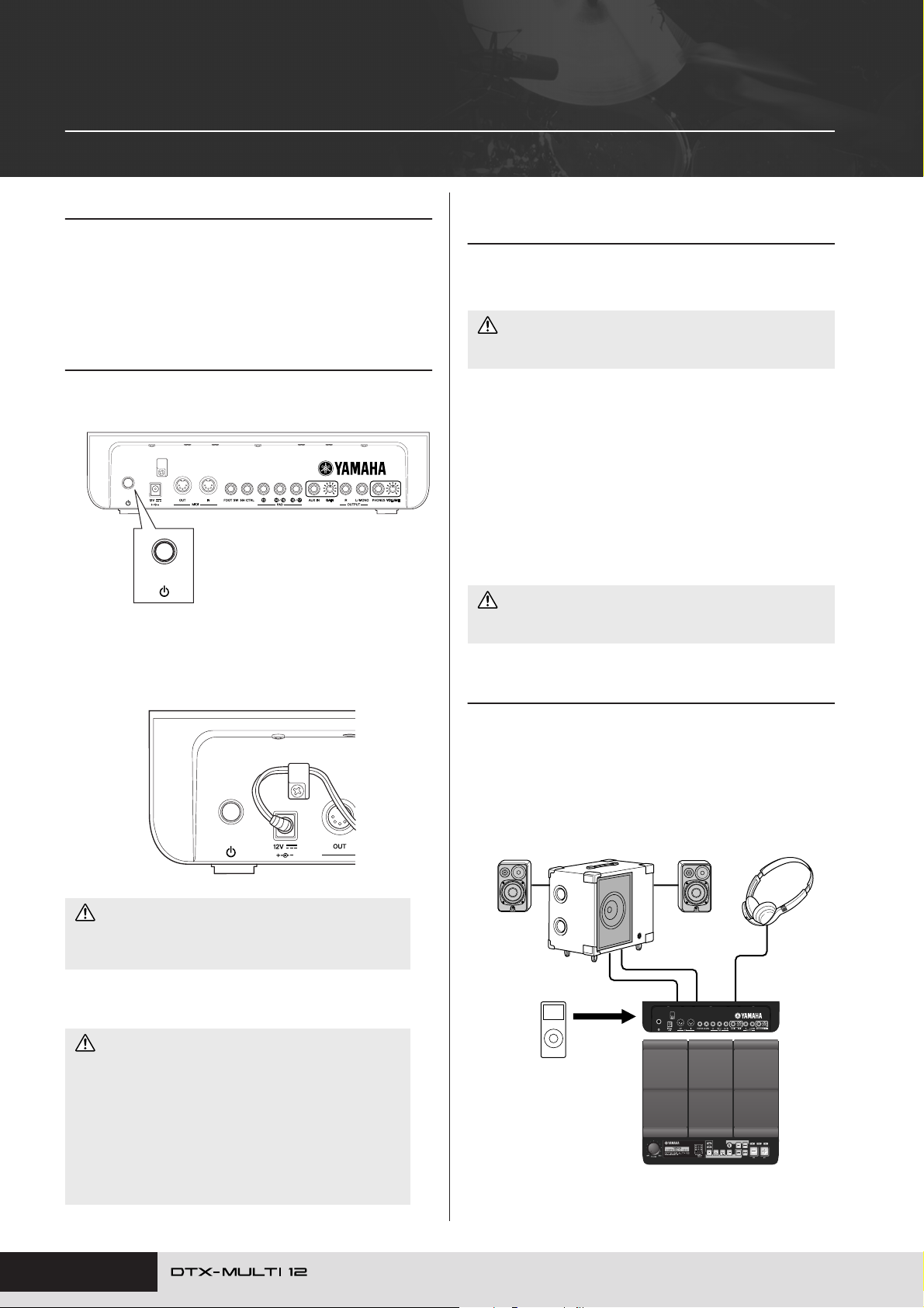
Connecting Speakers and/or Headphones
The DTX-MULTI 12 has no built-in speakers. In order to hear it,
therefore, you will need to connect headphones or an external
amplifier and speakers. (See the connection diagram below.)
CAUTION
• Whenever making connections, ensure that the plugs on the cables
being used match the DTX-MULTI 12’s output jacks.
● OUTPUT L/MONO and R Jacks
(standard mono audio jacks)
Use these jacks to connect your instrument to an external amplifier and speakers in order to hear yourself play. If the amplifier
has only a single input jack, be sure to connect it via the OUTPUT
L/MONO jack.
● PHONES Jack (standard stereo audio jack)
Use this audio jack to connect a pair of stereo headphones. The
headphone volume can be adjusted using the VOLUME knob on
the rear panel.
CAUTION
•To prevent hearing loss, avoid using headphones at high volumes
for extended periods of time.
Connecting to Other Audio Equipment
Audio input from an MP3 or CD player via the AUX IN jack can
be mixed with the sound produced by the DTX-MULTI 12 and
output together from the OUTPUT (L/MONO and R) and
PHONES jacks. This makes it very easy to play along with your
favorite tunes. If necessary, furthermore, you can adjust the input
volume using the GAIN knob.
CAUTION
• Ensure that the power cord is not bent at an extreme angle
when wrapped around the clip. Excessive bending can damage the cord and create a fire hazard.
Plug the adaptor’s AC power cord into an AC wall
3
socket or another electrical outlet.
WARNING
• Use only the power adaptor provided. Operation with other
adaptors may damage the instrument, cause it to overheat, or
create a fire hazard.
• Ensure that the power supply is correct for the power adaptor
provided.
• The DTX-MULTI 12 remains charged and draws a small
amount of power even when the (Standby/On) switch is in
the Off position. If it is not to be used for an extended period of
time, therefore, be sure to unplug the AC power adaptor from
the power supply.
10 Owner’s Manual
MS100DRJ or MS50DRJ Electronic
Drum Kit Monitor System, etc.
AUX IN
Por table music player, etc.
Headphones
PHONES jackOUTPUT L/MONO and R jacks
DTX-MULTI 12
Page 11

Setting Up
FF
FF
Turning on the DTX-MULTI 12
After you have connected speakers, an audio
1
player, and any other necessary equipment, turn
the volume of the DTX-MULTI 12 itself and the
other devices fully down as a precaution.
Press the (Standby/On) switch on the DTX-
2
MULTI 12’s rear panel to turn it on.
The opening screen will be displayed, followed by the Select
Kit page (from the KIT setting area).
≥≥≥≥≥YAMAHA
<<DTX-MULTI≥12>>
■ Connecting a mixer or other MIDI
devices
Ensure that the volume on all devices is turned fully down. Then,
turn on the devices one-by-one in the following sequence: q
MIDI controllers (master devices), w MIDI receivers (slave
devices), e audio equipment (mixers, amplifiers, speakers, etc.).
NOTE
• When turning off your system, first turn the volume of each audio device
fully down, and then switch off the devices one-by-one in the reverse order
to above (i.e., starting with the audio equipment).
■ Precautions When Using USB TO
DEVICE Port
Whenever connecting a USB device via the USB TO DEVICE
port, be sure to handle it with care and to observe the following
important precautions.
NOTE
•For more details on how to use your USB device, refer to the owner’s manual that came with it.
● Supported USB devices
Flash drives, external hard disks, and other USB-compatible,
mass-storage devices may be plugged in for use with this instrument.
The DTX-MULTI 12 does not necessarily support all commercially available USB memory devices, and Yamaha cannot guarantee the operation of all such devices that can be purchased.
Before purchasing a USB device for use with this instrument,
therefore, please check with your Yamaha dealer or an authorized
Yamaha distributor (see list at end of the Owner’s Manual) or visit
the following web page:
http://www.yamaha.co.jp/english/product/drums/ed/
NOTE
• Other USB devices, such as a computer keyboard or mouse, cannot be
used.
● Connecting a USB memory device
Before plugging in a USB memory device, ensure that its connector matches the instrument’s USB TO DEVICE port and that both
are oriented in the same direction.
This port supports the USB 1.1 standard; however, you can also
plug in and use USB 2.0 memory devices. It should be noted that
data will be transferred at the USB 1.1 speed in such a case.
Connecting a USB Memory Device
You can plug a USB memory device into the USB TO DEVICE
port on the side panel of your DTX-MULTI 12.
USB memory
device
DTX-MULTI 12
or
Connection to USB
memory device
(hard disk, etc.)
■ Using a USB Memory Device
With a USB memory device plugged in, you will be able to save
data that you have created and to import both settings and audio
data.
NOTE
• Although USB-type CD-R and CD-RW drives can be used to load data into
the instrument, they cannot be used to save data directly. You can, however, transfer data to a computer featuring a CD-R or CD-RW drive in order
to write it to this type of media.
● Formatting USB Memory Devices
Certain types of USB memory device must be formatted before
they can be used with this instrument. For details on how to do
this, see page 97.
CAUTION
• When a USB memory device is formatted, all data stored on it will
be permanently erased. Before formatting such a device, therefore,
ensure that any important data contained on it has been copied to
another location.
Owner’s Manual 11
Page 12
Setting Up
● Write Protection
Certain types of USB memory device can be write-protected to
prevent data from being accidentally erased. If your USB memory
device contains important data, we suggest that you use write protection to prevent accidental erasure. Meanwhile, if you need to
save data on such a device, be sure to disable the write-protect
function.
CAUTION
• If using a self-powered type of USB memory device, avoid turning it
on and off repeatedly. In addition, avoid frequent plugging and
unplugging of USB cables. If this precaution is not observed, the
DTX-MULTI 12 may freeze and stop operating.
•Never turn off either a plugged-in USB memory device or the DTXMULTI 12 or unplug the memory device while it is being accessed
within the UTILITY setting area in order to save, load, or delete
data or to perform formatting. If this precaution is not observed,
data on the USB memory device or the DTX-MULTI 12 may be corrupted.
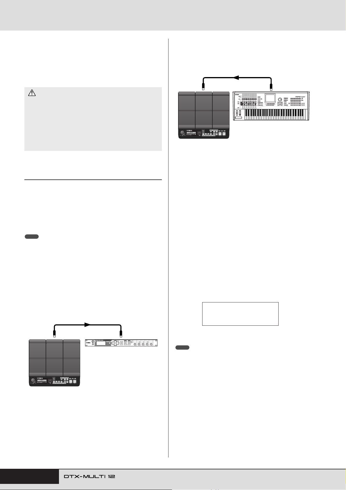
Connecting Other MIDI Devices
Using standard MIDI cables (sold separately), you can connect
other MIDI devices via the MIDI IN and MIDI OUT connectors.
When connected in this way, the DTX-MULTI 12 can be used to
control synthesizers and other sound modules. Meanwhile, the
instrument’s internal tone generator can be played using other
connected MIDI devices. These and many other MIDI functions
allow for an even greater range of performance and recording possibilities.
NOTE
• In addition to the two built-in MIDI connectors, the USB TO HOST port can
also be used to exchange MIDI data. Selection of whether to use the MIDI
connectors or the USB TO HOST port for this purpose is performed on the
MIDI In/Out page from the MIDI section of the UTILITY setting area (see
page 91).
■ To Control a Sound Module or Synthe-
sizer
Using a MIDI cable, connect the MIDI OUT connector on the
DTX-MULTI 12 to the MIDI IN connector on the device you
want to control or play.
■ To Control the DTX-MULTI 12 from
Another MIDI Device
Using a MIDI cable, connect the MIDI IN connector on the DTXMULTI 12 to the MIDI OUT connector on the controller device.
MIDI IN
connector
DTX-MULTI 12
● Synchronizing with Other MIDI Devices
MIDI cable
External MIDI device
MIDI OUT
connector
(Master and slave devices)
The playback of patterns on the DTX-MULTI 12 can be synchronized with playback on an external MIDI device. This instrument
and other MIDI devices use an internal clock to control the tempo
of playback, and when two such devices are synchronized, it is
necessary to specify which clock will be used by both. The device
set to use its own internal clock serves as a reference for all connected devices and is referred to as the “master” instrument. Connected devices set to use an external clock are referred to as
“slaves”. For example, if devices were connected as shown above
and you wanted to record playback data from the external MIDI
device as a pattern on the DTX-MULTI 12, it would be necessary
to set the external MIDI device as the master; furthermore, the
DTX-MULTI 12 would need to be setup to use an external clock
for synchronization. To do so, first of all press the [UTILITY] button to access the UTILITY setting area, navigate to the MIDI sec-
tion (UTIL6) using the [B]/[C] buttons, and press the [ENTER]
button. Next, navigate to the MIDI Sync page (UTIL6-6) using
the [B]/[C] buttons, and set the MIDI Sync parameter to either
“ext” or “auto”.
UTIL6-6≥≥≥<MIDI>
≥MIDI≥Sync=ext
MIDI OUT
connector
DTX-MULTI 12
12 Owner’s Manual
MIDI cable
MIDI IN
connector
External MIDI device
or
auto
NOTE
• The MIDI Sync parameter is set to “auto” by default.
Page 13
Setting Up
Within DTX-MULTI 12
Internal tone
generator
On
Off
Sound is produced
Local Control Settings
No sound is
produced.
Connecting to a Computer
Although the DTX-MULTI 12 is exceptionally powerful and versatile all by itself, connecting it to a computer via USB allows for
even greater power and versatility. When connected in this way,
MIDI data can be freely transferred between the instrument and
the computer. In this section, you’ll learn how to make the necessary connections.
NOTE
• As the DTX-MULTI 12 has no built-in speakers, you will need to connect
headphones or an external amplifier and speakers in order to hear it. For
details, see page 10.
•A USB cable is not included. In order to connect to a computer, use a USB
A-B cable of no more than 3 meters in length.
Download the latest version of the USB-MIDI
1
driver to your computer from the following web
page. After clicking the Download button, save
the compressed file in a convenient location and
then expand it.
http://www.global.yamaha.com/download/usb_midi/
NOTE
• Information on system requirements is also provided on the above web
page.
• The USB-MIDI driver may be revised and updated without prior notice.
Before installing, visit the above web page to confirm the latest related
information and ensure that you have the most up-to-date version.
■ Precautions When Using USB TO HOST
Port
When connecting to a computer via the USB TO HOST port, be
sure to observe the precautions listed below. Failing to do so risks
freezing your computer and corrupting or losing data. If your
computer or DTX-MULTI 12 should freeze, restart the application being used, reboot the computer, or turn the instrument off
once and then back on.
CAUTION
• Use a USB A-B cable of no more than 3 meters in length.
• Before connecting to the computer via the USB TO HOST port,
restore the computer from any power-saving mode (such as Suspend, Sleep, or Standby).
• Connect the computer via the USB TO HOST port before turning
on the DTX-MULTI 12.
• Be sure to always perform the following steps before turning the
instrument on or off and either plugging or unplugging the USB
cable.
• Quit all applications.
• Ensure that no data is being sent from the DTX-MULTI 12. (Data
is transmitted by striking the pads or playing patterns.)
• When connected to a computer, allow at least 6 seconds to pass
between turning the instrument on and off and plugging or unplugging the USB cable.
Install the USB MIDI driver on your computer.
2
For instructions on installing, refer to the guide included with
the driver installer. When the guide indicates that your
Yamaha product should be connected to the computer, do so
as shown below.
USB TO HOST port
USB port
Computer
USB cable
To enable the exchange of MIDI data via the USB
3
TO HOST port, press the [UTILITY] button to
DTX-MULTI 12
access the UTILITY setting area and then navigate to the MIDI In/Out page (UTIL6-9).
UTIL6-9≥≥≥<MIDI>
MIDI≥IN/OUT=MIDI
Set the MIDI IN/OUT parameter to “USB” (using
4
the [+/INC] button if necessary).
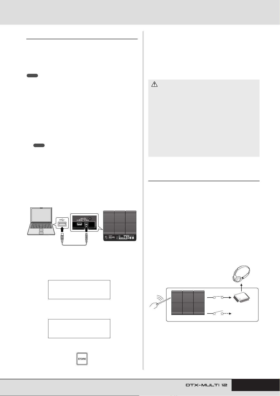
Making Music with a Computer
■ Recording DTX-MULTI 12 Performance
Data using a DAW Application
The following section will describe how to record your performances using a DAW application running on a connected computer.
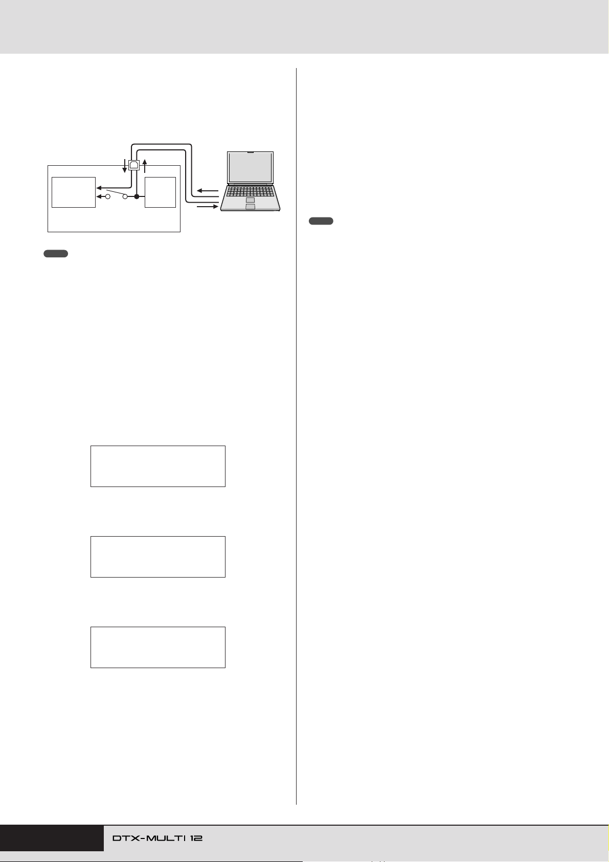
Normally, when playing in order to record on a computer, performance data produced by striking the pads is first sent to the computer and then returned to the instrument in order to play its
internal tone generator. If local control of the DTX-MULTI 12 is
turned on (via the Local Control page (UTIL6-5) from the UTILITY area), performance data will also be sent directly to the tone
generator, and as a result, the direct and returned data will overlap, making it sound as if the pads are being struck twice.
UTIL6-9≥≥≥<MIDI>
MIDI≥IN/OUT=USB
Press the [STORE] button and store this setting.
5
Owner’s Manual 13
Page 14
Setting Up
Most DAW applications allow MIDI Thru to be turned on, and
therefore, you can setup your system as shown below with local
control of the DTX-MULTI 12 turned off and the DAW application returning performance data to the tone generator. In this way,
performances can be recorded in comfort without each strike
being heard twice.
USB TO HOST port
DTX-MULTI 12
Internal
tone
generator
Local control
LocalCtrl =“off”
NOTE
•DAW is an abbreviation of digital audio workstation. DAW applications such
as Cubase can be used to record, edit, and mix audio and MIDI data on a
computer.
We will now describe how to setup parameters for recording your
performances, first on the instrument itself, and then within the
DAW application.
● DTX-MULTI 12 settings
Turn off local control as follows.
Press the [UTILITY] button to access the UTILITY
1
setting area, navigate to the MIDI section (UTIL6)
using the [BBBB]/[CC
OUTIN
Pads
IN
CC
] buttons, and press the
Computer
OUT
MIDI Thru turned
on within DAW
application.
[ENTER] button.
● Setting DAW-Application Parameters
Within your DAW application, turn on MIDI Thru. This setting
ensures that, when performance data is being recorded on a track
within your application, it is also returned to the external MIDI
system.
For example, let’s assume that performance data is being recorded
on Track 3 by your DAW application. In addition, we’ll also
assume that MIDI Channel 1 has been set for the return of performance data. If MIDI Thru is now turned on for Track 3, the DAW
application will return the performance data to the DTX-MULTI
12 as it is being recorded, and the instrument’s internal tone generator will sound as if it is being played directly (on Channel 1).
NOTE
•For details on how to turn on MIDI Thru, refer to the manual that came with
your DAW application.
• If local control on the DTX-MULTI 12 and MIDI Thru within your DAW application are both turned off, no performance data will be sent to the internal
tone generator, either directly or indirectly. As a result, no sound will be produced.
■ Playing the DTX-MULTI 12 using MIDI
Data from a DAW Application
As described below, you can setup the DTX-MULTI 12 to operate
as a multi-timbral tone generator for your DAW application. In
this way, you can easily integrate the instrument’s high-quality
MIDI tone generator into your music-production setup. For
details on how to connect the DTX-MULTI 12 to your computer,
see page 13.
Set each of the tracks within your DAW applica-
1
tion to output their MIDI data to the DTX-MULTI
12.
UTIL6
≥≥≥≥≥≥MIDI
Navigate to the Local Control page (UTIL6-5)
2
using the [BBBB]/[CC
CC
] buttons.
UTIL6-5≥≥≥<MIDI>
≥LocalCtrl=on
Set the LocalCtrl parameter to “off” (using the [-/
3
DEC] button if necessary).
UTIL6-5≥≥≥<MIDI>
≥LocalCtrl=off
Press the [STORE] button and store this setting.
4
With local control turned off in this way, performance data produced by striking the pads will not be sent to the internal tone
generator.
Play MIDI performance data using the DAW appli-
2
cation.
14 Owner’s Manual
Page 15
Setting Up
<<≥≥≥Cubase≥≥≥>>
<<≥≥≥Remote≥≥≥>>
E
Setting up Cubase Remote Control
Using a special feature, the DTX-MULTI 12 can operate as a
remote controller for Cubase. For example, you can operate the
Cubase transport, turn its metronome on or off, and control various other functions from the instrument’s front panel, significantly increasing the efficiency of your music production
workflow.
■ Computer settings
When setting up Cubase remote control for the first time, complete the following steps to configure your computer correctly.
Download the latest version of the DTX-MULTI 12
1
Extension from the following web page.
Save the compressed file in a convenient location and then
expand it.
http://www.yamaha.co.jp/english/product/drums/ed
NOTE
• Ensure that the latest USB MIDI driver is installed on your computer
(see page 13).
• Information on system requirements is also provided on the above web
page.
• The DTX-MULTI 12 Extension may be revised and updated without
prior notice. Before installing, visit the above web page to confirm the
latest related information and ensure that you have the most up-todate version.
Execute the expanded DTX-MULTI 12 Extension
2
to carry out the required installation procedure.
For more details, refer to the owner’s manual
included in the downloaded package.
Hold down the [SHIFT] button and press the
3
[MIDI] button.
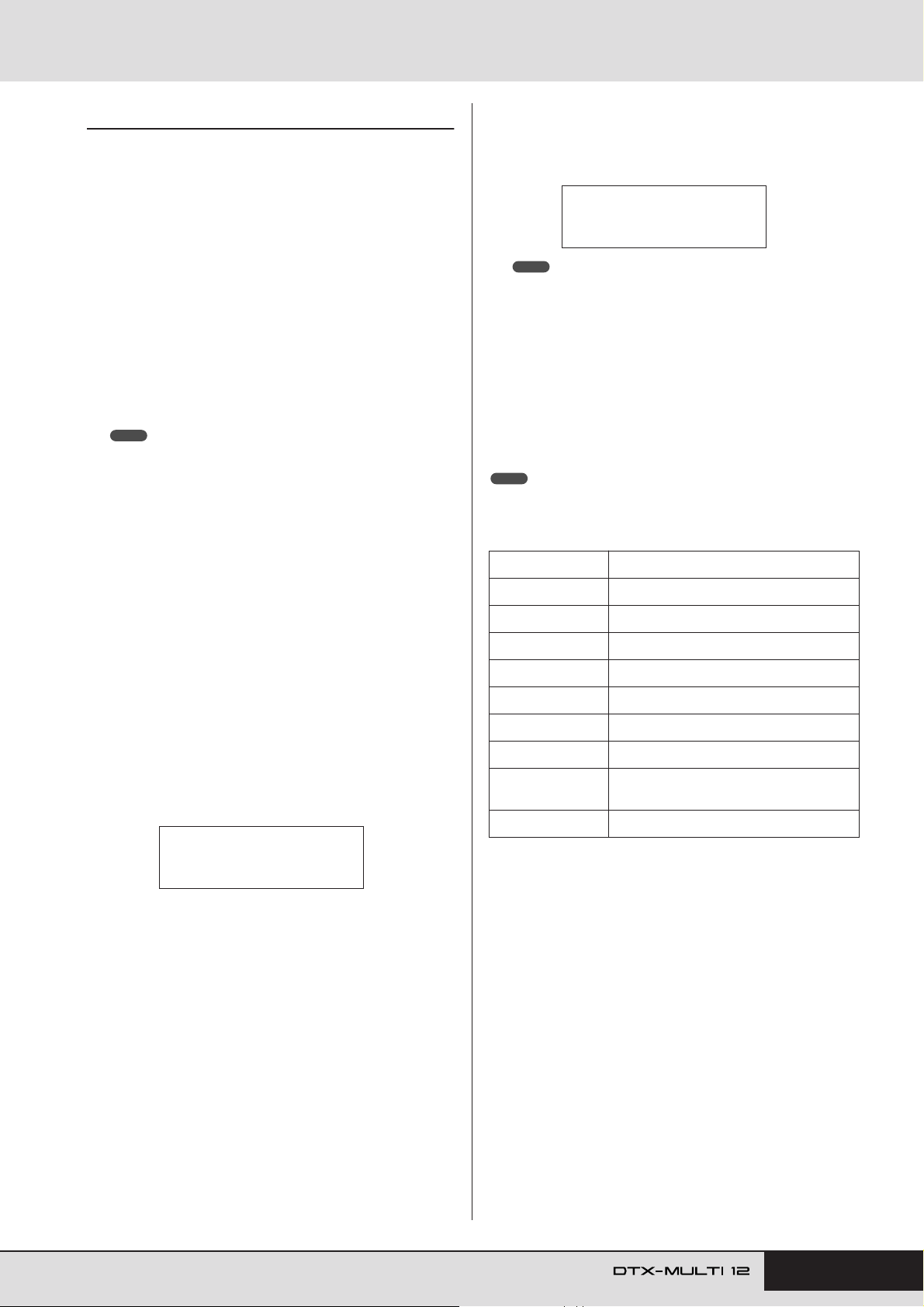
The message “Cubase Remote” will be displayed to confirm
that the function has been activated.
NOTE
• When Cubase Remote mode has been activated, those front-panel
buttons that can be used will light up.
To deactivate Cubase Remote mode, again hold
4
down the [SHIFT] button and press the [MIDI] button.
■
Button Functions in Cubase Remote
Mode
NOTE
•For more details regarding the operation of Cubase Remote mode, refer to
the owner’s manual included in the downloaded package.
Button Operation
[SHIFT] + [MIDI] Turns the Cubase Remote function on and off.
[KIT] Opens the VSTi window.
[PTN] Starts and stops playback.
■ DTX-MULTI 12 settings
Whenever the Cubase Remote function is to be used, the following steps must be completed on the DTX-MULTI 12.
Within the UTILITY setting area, navigate to the
1
MIDI In/Out page (UTIL6-9) and set MIDI IN/OUT to
“USB”.
UTIL6-9≥≥≥<MIDI>
MIDI≥IN/OUT=USB
Ensure that the DTX-MULTI 12 is connected to
2
your computer in the correct manner, and then
launch Cubase.
For more details regarding connection, see page 13.
[SHIFT] + [PTN] Starts recording.
[-/DEC], [+/INC] Increases or decreases a preset by 1.
[B]Rewinds the transport (REW).
[C]Fast forwards the transport (FF).
[D]
Returns the transport to the start of the song
(TOP).
Tu r ns the click track on and off.
Owner’s Manual 15
Page 16
Producing Sounds with the Pads
In order that you can start having fun with your DTX-MULTI 12 as soon as possible, this section will begin by
explaining the basic way in which the pads can be played using drum sticks (sold separately), and following
that, will show how to select various kits (i.e., sets of pad sounds).
Pad Names
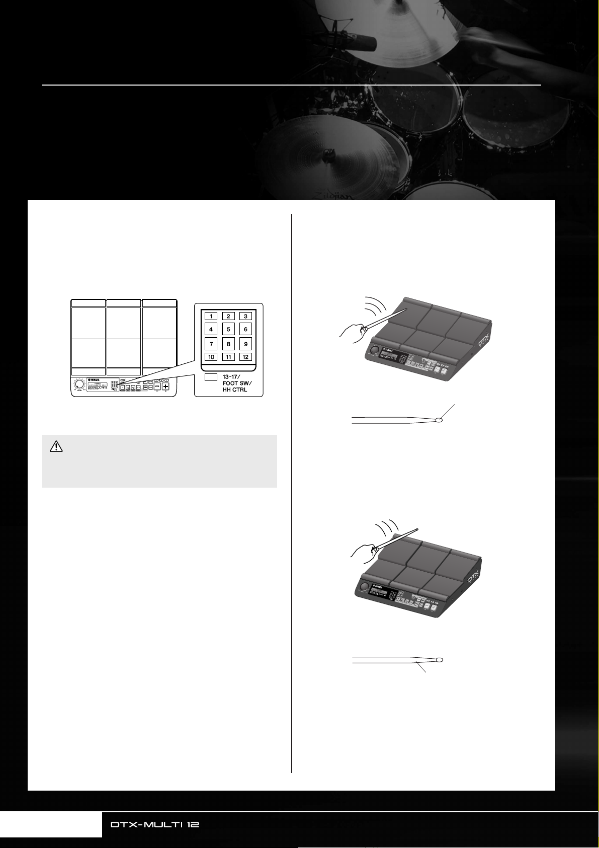
As shown below, numbers 1 through 12 are assigned to the builtin pads. These numbers are also shown at the corresponding
positions within the Pad Indicator, and they will light up when
the associated pad is struck.
123
456
789
10 11 12
Pad Indicator
CAUTION
• Do not place your fingers into the gaps between Pads 1 to 3 and
the instrument's plastic body. If this precaution is not observed,
your fingers may be injured as a result of crushing or squeezing.
Striking the Pads
When playing Pads 4 to 9 (i.e., the main pads), aim to strike the
center of the pad with the tip of the drum stick.
● Playing Pads 4 to 9
Area of drumstick to use
Meanwhile, when playing Pads 1 to 3 and Pads 10 to 12 (i.e., the
rim pads), aim to strike the center of the pad with the shoulder of
the drum stick.
● Playing Pads 1 to 3 and Pads 10 to 12
Tip
16 Owner’s Manual
Area of drumstick to use
Shoulder
Page 17
Producing Sounds with the Pads
KIT1
P001:PercsMaster
KIT1≥≥≥≥≥≥≥ˇÁ
P001:PercsMaster
● Kit suitable for playing by hand
KIT1
U001:User≥Kit
● User-defined kit
Starts with “U”
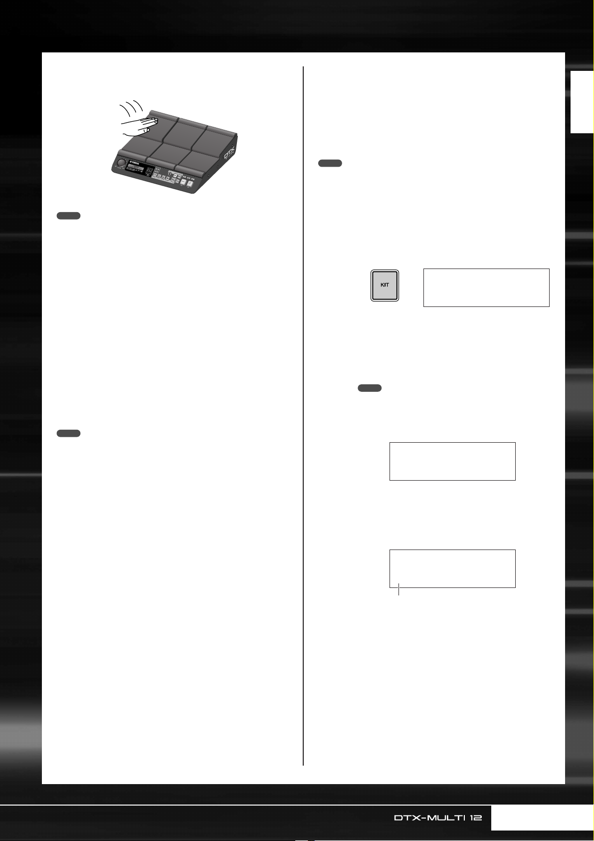
You can also adjust the sensitivity of the pads to allow them to be
played by hand (see page 19).
NOTE
•Drum and other individual instrument sounds known collectively as preset
voices and rhythmic or musical phrases known as patterns can be
assigned to each of the pads. Whenever you strike a pad to which a pattern has been assigned, the pattern will either be played through just once
(one-shot) or repeated (loop), and the corresponding lamp within the Pad
Indicator will light up. If a pad playing a looped pattern is struck again, the
pattern will stop playing and the lamp will go out.
• If looping patterns are assigned to multiple pads and you loose track of
which ones are actually being played, you can silence all sound output by
holding down the [SHIFT] button and pressing the [EXIT] button.
• If a pad is struck too lightly or very close to an edge or corner, the corresponding lamp in the Pad Indicator may not turn on.
■ Muting
Muting is the action of placing a hand on a struck percussion
instrument in order to silence it, and the DTX-MULTI 12 pads
support this playing technique. In addition, when multiple
sounds have been assigned to a pad, you can use also muting to
switch between these sounds for more expressive performances.
NOTE
•For details on how to switch sounds by muting, see page 51.
Selecting a Preset Kit
The term “kit” is used to refer to a collection of sounds (i.e., preset voices, waves, and patterns) produced when you strike each
of the pads, and the DTX-MULTI 12 comes complete with an
impressive range of specially-prepared preset kits. Using the procedure outlined below, select various kits and enjoy some of the
stunning sounds that your instrument can produce.
NOTE
• The screen displays shown in this Owner’s Manual are for instructional
purposes only, and they may appear somewhat different from those on
your DTX-MULTI 12.
Press the [KIT] button to open the Select
1
2
Kit page.
The [KIT] button will light up.
Use the [-/DEC] and [+/INC] buttons to
select a new drum kit.
Try playing the each of the pads from various different types of kit.
NOTE
•A number of the Preset kits have been specially setup for
playing by hand. When you select one of them, a hand icon
will be displayed on-screen as shown below.
Quick Guide
• Kits having a number preceded by the letter “U” are User kits
(i.e., user-defined kits). With these kits, you can create and
save your own collections of preset voices, patterns, and
waves.
Owner’s Manual 17
Page 18
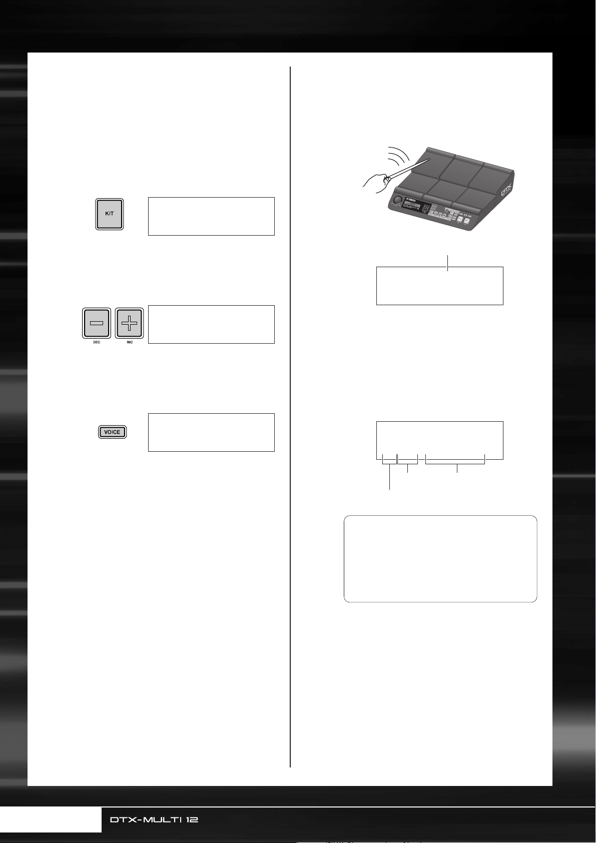
Producing Sounds with the Pads
Assigning Preset Voices to Pads
In the following simple example, we will create a User kit by
replacing one of the sounds assigned to the pads in a Preset kit.
Specifically, we will assign a voice to Pad 4 from the selected kit,
and we will then save the resultant kit to the empty User kit
U001.
Press the [KIT] button to open the Select
1
2
3
Kit page.
KIT1
P001:PercsMaster
Use the [-/DEC] and [+/INC] buttons to
select a kit to work with.
KIT1
P009:Oak≥Custom
Press the [VOICE] button to open the
Select Voice page.
4
5
Strike Pad 4 to select it and to change the
displayed pad number to .
Alternatively, you can move the flashing cursor to the
pad number, and then change it from to
-º¢-
Select the voice you want to assign to Pad
4.
Move the flashing cursor to the leftmost parameter
from the lower row of text, and using the [-/DEC] and
[+/INC] buttons, select the voice category and voice
number of the voice you wish to assign.
using the [-/DEC] and [+/INC] buttons.
VCE01≥≥-º¢-≥≥≥
Tm001:OakCtm≥H
-º¢-
-º¡-
Pad number
VCE01≥≥-º¡-≥≥≥
Cy013:Thin16Eg
VCE01≥≥-º¢-≥≥≥
Sn004:MapleCtm
Voice nameVoice number
Voice category
Voice Categories
Similar voices are grouped together in voice
categories. In addition to melodic instruments
such as timpani and marimba, you can also
select voice categories containing Preset patterns, User patterns, and waves. For more
information, refer to the Data List booklet.
18 Owner’s Manual
Page 19
Producing Sounds with the Pads
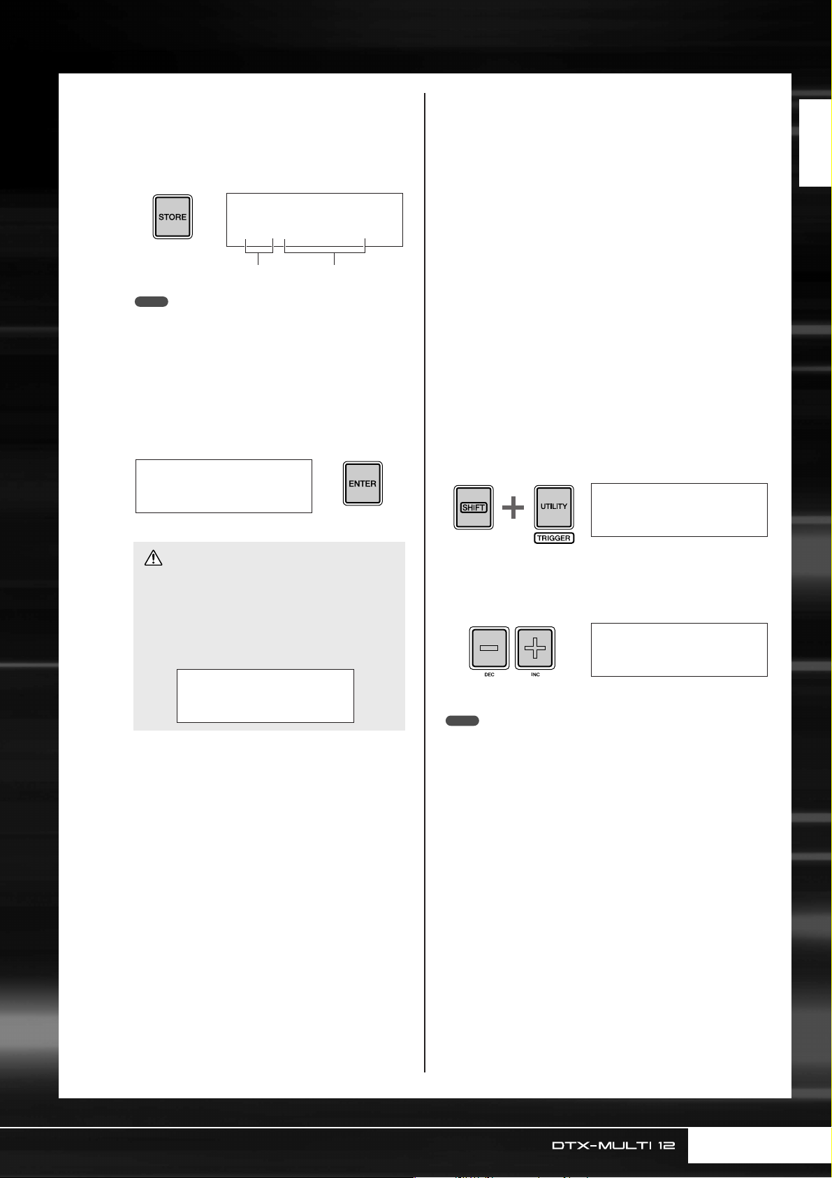
6
7
Press the [STORE] button and store the
edited kit as a User kit.
As shown here, select the empty User kit U001, using
the [-/DEC] and [+/INC] buttons if necessary, and
then press the [ENTER] button.
VCE≥Store≥to
U001:User≥Kit
User kit number User kit name
NOTE
• The [STORE] button will light up whenever settings have
been changed but not yet stored in the DTX-MULTI 12’s internal memory. The button will, therefore, go out when the modified settings are stored.
When asked to confirm that you want to
store the kit, press the [ENTER] button to
proceed.
≥≥≥KIT≥Store
≥Are≥you≥sure?≥≥
■ Layers
Using the Layer function, you can assign a number of different
voices to a single pad or external controller. Up to four layers (A
to D) to be setup per pad, meaning that each pad can play as
many as four different voices. Furthermore, a number of different
playback modes can be employed for voices assigned to layers.
For example, these voices can be triggered simultaneously, a different one can be played each time the pad is struck, or they can
alternate between on and off upon successive hits. Details on layers can be found on page 32.
■ Playing by hand
The DTX-MULTI 12 features a number of different preset kits
suitable for hand percussion – that is, for playing with hands
instead of drum sticks. As described below, furthermore, you can
use a trigger setup at any time to adjust the sensitivity of the pads
to suit playing by hand.
● Setting pad sensitivity for playing by hand
q Hold down the [SHIFT] button and press the [UTILITY] but-
ton to access the Trigger setting area. The Select Trigger
Setup page will be displayed.
TRG1≥≥≥≥≥≥≥≥≥≥
P01:Stick≥Wide≥≥
Quick Guide
8
CAUTION
• The message ”Please keep power on...” will be displayed while data is being stored. It is very important
that the DTX-MULTI 12 is not turned off until this
message disappears. If the instrument were to be
turned off at this time, data for all User kits could be
permanently lost.
≥≥Please≥keep
≥≥power≥on...
With User pad U001 selected, strike Pad 4
to hear the voice that you assigned.
w Use the [-/DEC] and [+/INC] buttons to select the “P04:
Hand” or “P05: Finger” trigger setup.
TRG1≥≥≥≥≥≥≥≥≥≥˛¸
P04:Hand
NOTE
• Whenever you select a hand-percussion preset kit, the pad sensitivity (i.e.,
the trigger setup) will automatically change to suit playing by hand.
•Very high levels of pad sensitivity are more likely to result in a phenomenon known as crosstalk, where pads other than the one struck trigger
sounds due to vibration or interference between pads.
•For details on how to configure trigger setups in the Trigger setting area,
see page 99.
Owner’s Manual 19
Page 20
Listening to Patterns
Your DTX-MULTI 12 has been pre-loaded with a rich variety of melodic and rhythmic phrases in the form of Preset patterns. The first three Preset patterns (eP001 to eP003) have been specially setup to demonstrate the rich
spectrum of sounds that your DTX-MULTI 12 can produce. Patterns numbered eP004 and higher can be freely
assigned to pads for use in your own User drum kits.
Listening to Demo Patterns
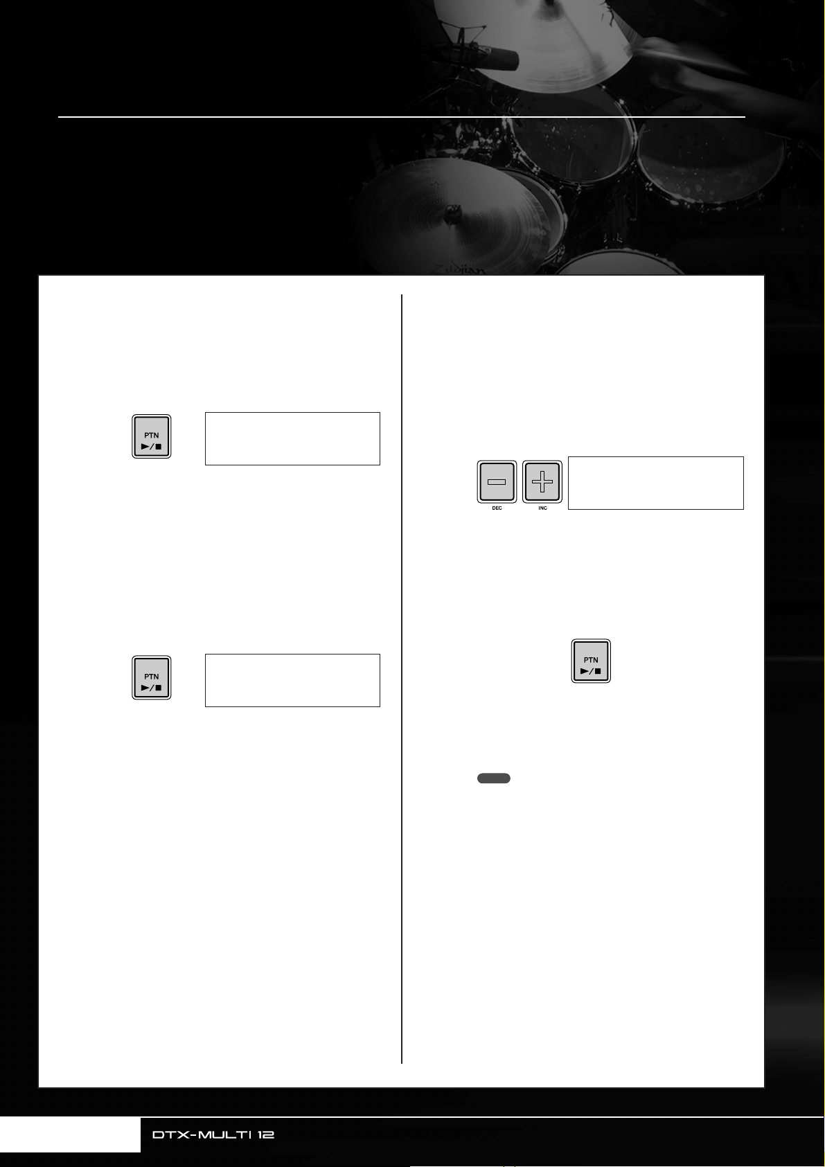
Press the [PTN] button to open the Select
1
2
Pattern page.
The [PTN] button will light up. Demo patterns are
numbered eP001 to eP003.
PTN1≥≥≥ƒ=120≥4/4
©P001:Demo≥01
Press the [PTN] button once again to start
playback of a demo pattern.
The [PTN] button will flash while the demo pattern is
being played, and the name of the pattern will be displayed inside “<<” and “>>” characters on the upper
row of text. Furthermore, the lower row of text will
shown the name of the kit being used for playback of
the demo pattern.
≥<<Demo≥01>>
P039:Orchestra
Listening to Preset Patterns
Press the [PTN] button to open the Select
1
2
3
Pattern page.
Select the Preset pattern you want to listen
to using the [-/DEC] and [+/INC] buttons.
Select a Preset pattern numbered eP004 or higher.
PTN1≥≥≥ƒ=120≥4/4
©P004:80s≥Electo
Press the [PTN] button once again to start
playback of the selected Preset pattern.
The [PTN] button will flash while the Preset pattern is
being played.
To stop the demo pattern, press any button
3
20 Owner’s Manual
other than [SHIFT].
4
To stop the pattern, press the [PTN] button
on the Select Pattern page (PTN1).
NOTE
• If you wish to assign a Preset pattern to a pad, follow the procedure described on page 18, and at Step 5, select the Preset pattern instead of a preset voice.
Page 21
Making Your Own Patterns
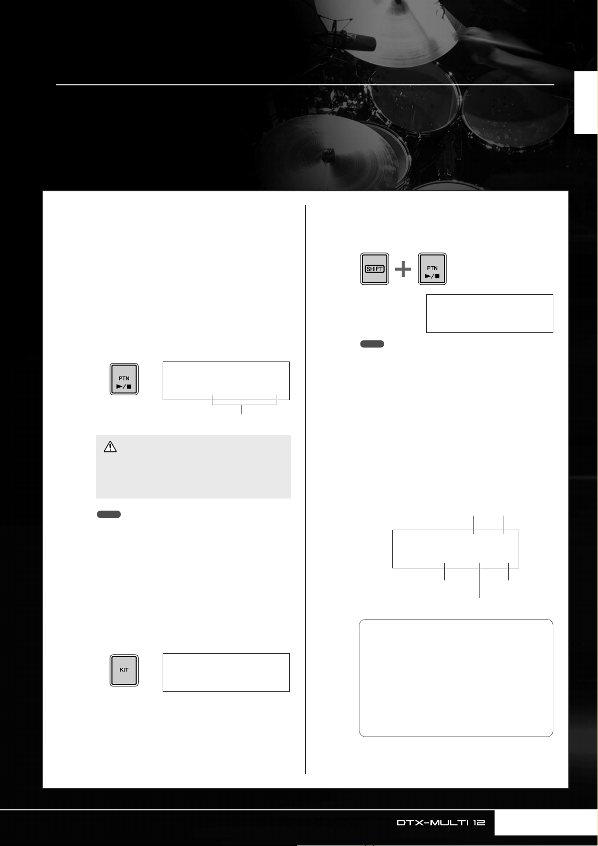
REC≥≥≥≥ƒ=120≥4/4
Meas=004≥Q=©≥≥-“
REC≥≥≥≥ƒ=120≥4/4
Meas=004≥Q=©≥≥-“
t Playback modee Length
r Quantize
q Tempo w Time signature
q Tempo: The speed of the pattern in beats
per second.
w Time signature: The time signature of the
pattern to be recorded.
e Length: The length of the pattern in mea-
sures.
r Quantize: The precision of timing correc-
tion for the recorded pattern.
t Playback mode: The type of pattern to be
recorded – i.e., one-shot or loop.
Using the DTX-MULTI 12, you can also create User patterns by recording your own performances. And in the
same way as Preset patterns, these User patterns can then be freely assigned to pads and played back.
Quick Guide
Recording Your Performance as a
Pattern
Following the steps below, let’s create a User pattern by recording a performance and then assign that pattern to Pad 6.
Press the [PTN] button to access the Pat-
1
tern setting area, and select an empty User
pattern using the [-/DEC] and [+/INC] buttons.
Empty User patterns are named “Empty Ptn”.
PTN1≥≥≥ƒ=120≥4/4
©U003:Empty≥Ptn
Pattern name
CAUTION
• If you select a User pattern already containing data,
your performance will be added to that data as a
result of recording. If you want to avoid this, be sure
to select an empty User pattern for recording.
3
4
Hold down the [SHIFT] button and press
the [PTN] button to activate Record Mode.
The [PTN] button will turn red.
NOTE
• If a Preset pattern is selected when you activate Record
Mode, your performance will be recorded to an empty User
pattern.
Set the required recording conditions.
On the Record Mode screen (REC), you can set the
tempo and time signature of the click track to be
played when recording, the length of the pattern in
measures (or bars), and a number of other important
parameters. Move the flashing cursor to the required
parameter using the [B], [D], and [C] buttons, and
change the setting using the [-/DEC] and [+/INC] buttons.
NOTE
• If you select a User pattern already containing data for
recording, you can add additional performance data to that
pattern as you record.
•Two existing patterns can be merged to create a new User
pattern (see page 79).
Press the [KIT] button to open the Select
2
Kit page, and using the [-/DEC] and [+/INC]
buttons, select the drum kit you want to
use for recording your pattern.
KIT1
P001:PercsMaster
Owner’s Manual 21
Page 22
Making Your Own Patterns
5
6
7
Press the [PTN] button to start recording.
The DTX-MULTI 12 will count you in over two measures. Then, play the pattern you want to record in
time with the click track.
Measure currently being recorded
REC≥Meas=≥001
Now≥Recording...
CAUTION
•Turning off the DTX-MULTI 12 while recording can
result in data for all User patterns being lost and
must, therefore, be avoided.
Recording will end automatically after the
number of measures set as the pattern
length in Step 4 above.
The message ”Please keep power on...” will be displayed for a short period of time as data is being
stored.
≥Please≥keep≥≥≥
≥power≥on...
CAUTION
•Turning off the DTX-MULTI 12 while the message
”Please keep power on...” is being displayed can
result in all User-pattern data being lost and must,
therefore, be avoided.
NOTE
• Recording can be stopped at any time by pressing the [PTN]
button. All performance data recorded up to that point will be
stored.
• If looped playback was selected in Step 4 above, recording
can be ended by pressing the [PTN] button.
When the Pad Assign page is displayed,
strike Pad 6 to display pad number ,
and then press the [ENTER] button.
Alternatively, you can use the [-/DEC] and [+/INC]
buttons to select on this page.
º§
º§
8
9
10
11
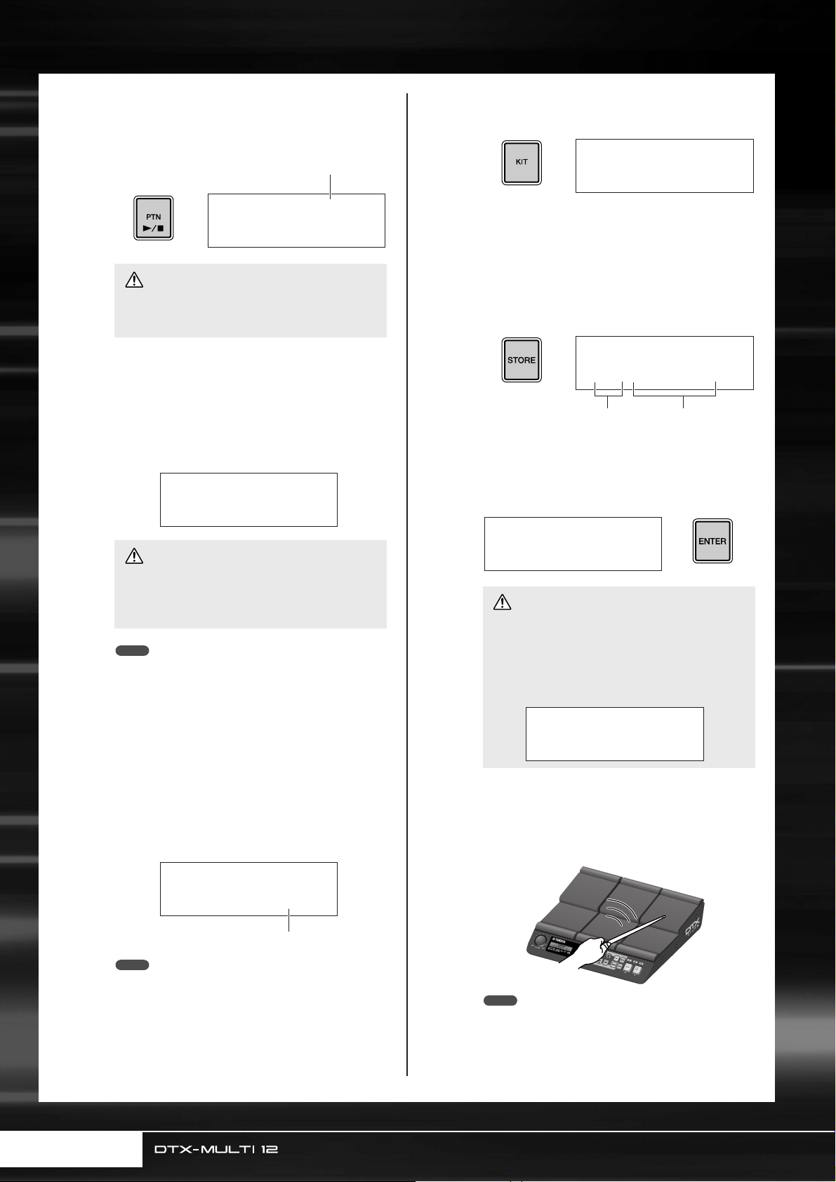
Press the [KIT] button to access the KIT
setting area.
KIT1
P001:PercsMaster
Press the [STORE] button and store the
current kit and its new pattern assignment
as a User kit.
As shown here, select an empty User kit using the [-/
DEC] and [+/INC] buttons, and then press the
[ENTER] button.
VCE≥Store≥to
U001:User≥Kit
User kit number User kit name
When asked to confirm that you want to
store the kit, press the [ENTER] button to
proceed.
≥≥≥KIT≥Store
≥Are≥you≥sure?≥≥
CAUTION
• The message ”Please keep power on...” will be displayed while data is being stored. It is very important
that the DTX-MULTI 12 is not turned off until this
message disappears. If the instrument were to be
turned off at this time, data for all User kits could be
permanently lost.
≥≥Please≥keep
≥≥power≥on...
With the stored drum kit selected, strike
Pad 6 to hear the pattern that you
assigned.
NOTE
• If you set PadAssign to “off”, the recorded pattern will not be
• Although you can freely assign the recorded pattern to a pad
22 Owner’s Manual
REC
≥PadAssign=º§
Pad number
assigned to any pad.
at any time, it is best to use a pad from the drum kit selected
in Step 1 above. If you assign it to a pad from another kit, the
pattern may not play as recorded.
NOTE
• Up to 50 User patterns can be recorded on your DTX-MULTI
12. If an attempt is made to record more than this number,
the message “Seq data is not empty” will be displayed and
the recording process will end. In such a case, delete
unneeded User patterns (see page 79) and begin recording
again.
Page 23
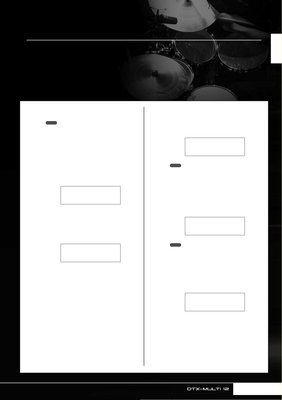
UTIL7-1-1
Type=All
UTIL7-1-2
Name[≥≥≥≥≥≥≥≥≥≥]
≥≥≥Save≥File
≥Are≥you≥sure?
Saving Your Data on a USB Memory Device
Data that you have made, such as User kits and User patterns, can be conveniently saved as combined files on
a USB memory device. In the following example, we will create a single file containing all of the data created or
modified in the various DTX-MULTI 12 setting areas on a such a device.
Quick Guide
1
2
3
Plug a USB memory device into the USB
TO DEVICE port on the side panel.
NOTE
•For more details regarding USB memory devices, see the
section Connecting a USB Memory Device on page 11.
Press the [UTILITY] button to access the
BB
CC
BB
]/[CC
UTILITY setting area, use the [
tons to navigate to the FILE section
(UTIL7), and then press the [ENTER] button.
UTIL7
≥≥≥≥≥≥FILE
Navigate to the Save File page (UTIL7-1),
BB
CC
BB
]/[CC
using the [
and then press the [ENTER] button.
UTIL7-1
≥≥≥Save≥File
] buttons if necessary,
] but-
4
5
6
Set Type to “All”, using the [-/DEC] and [+/
INC] buttons if necessary.
When you have made this setting, press the [ENTER]
button.
NOTE
•For details on saving data with a Type setting other than “All”,
see page 93.
Enter a name for the file to be saved.
For more details on how to input characters and the
types of character that can be used for file names, seesee page 47.
NOTE
• File names can be up to eight characters in length.
When you have entered the required name,
press the [ENTER] button.
You will be asked to confirm that you want to save the
file, and the [ENTER] button will flash on and off.
Owner’s Manual 23
Page 24
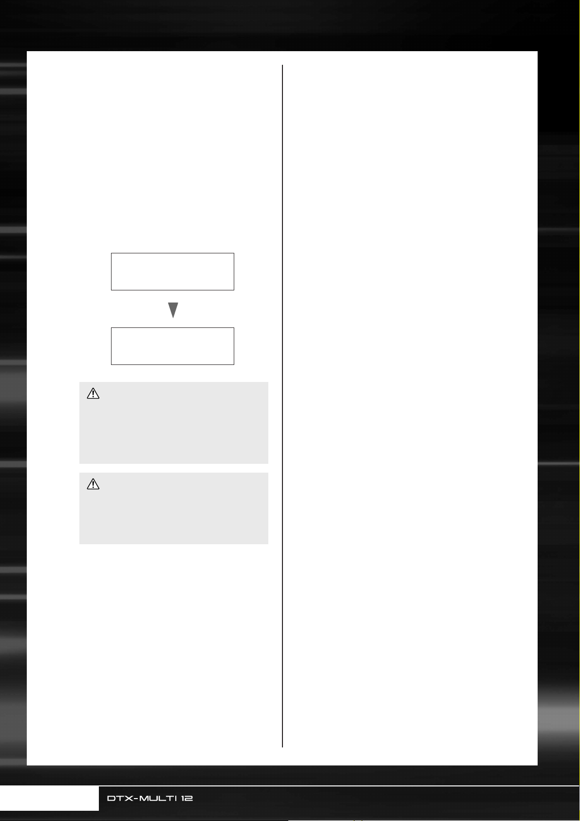
Saving Your Data on a USB Memory Device
To proceed, press the [ENTER] button one
7
more time.
If a file with the same name already exists on the USB
memory device, you will be asked to confirm whether
you want to overwrite it. If that file is no longer
needed and can be overwritten, press the [ENTER]
button. Alternatively, if the older file contains important data, press the [EXIT] button to return to the
Name page and repeat the procedure from Step 5
above using a different file name.
The message “Now saving... [EXIT] to cancel” will
be displayed while your data is being saved. The message “Completed.” will then be displayed when the
data has been saved, and the display will return to the
Save File page (UTIL7-1) from Step 4 above.
≥Now≥Saving
[EXIT]≥to≥cancel
Completed
CAUTION
• Do not unplug the USB memory device from the USB
TO DEVICE port or turn off either the USB memory
device or the DTX-MULTI 12 while data is being
loaded or saved. Failure to observe this precaution
can lead to the USB memory device or the DTXMULTI 12 being permanently damaged.
CAUTION
• Be sure to always unplug USB memory devices from
the DTX-MULTI 12 before you start to play. If you
were to accidentally strike a memory device with a
drum stick while playing, it could be permanently
damaged and all data saved on it could be lost.
24 Owner’s Manual
Page 25
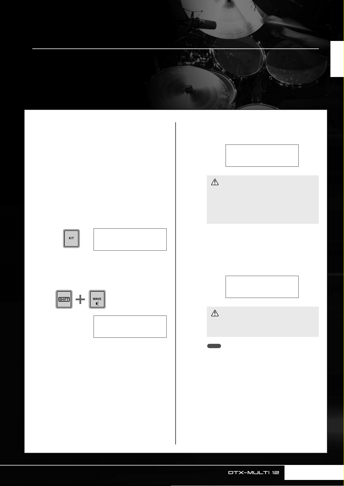
Importing Audio Files
Now≥Importing...
[EXIT]≥to≥cancel
IMPORT
≥PadAssign=º¡
WAV and AIFF audio files from your computer and other media can be imported into your DTX-MULTI 12 via
USB memory devices. Referred to as “waves”, these voices can then be assigned to pads and played in the
same way as any other preset voice.
Quick Guide
1
2
3
4
Using a computer, place the WAV or AIFF
file(s) for importing at the root directory of
a USB memory device.
Unplug the USB memory device from the
computer and plug it into the instrument
via the USB TO DEVICE port on the side
panel.
Press the [KIT] button to open the Select
Kit page and then select the drum kit to
which the imported wave(s) will be
assigned.
KIT1
U001:User≥Kit
Hold down the [SHIFT] button and press
the [WAVE] button to open the Import page.
6
7
When you have made your selection, press
the [ENTER] button to import the file.
CAUTION
• Do not unplug the USB memory device from the USB
TO DEVICE port or turn off either the USB memory
device or the DTX-MULTI 12 while data is being
loaded. Failure to observe this precaution can lead to
the USB memory device or the DTX-MULTI 12 being
permanently damaged.
Once the audio file has been imported, the
Pad Assign page will open. Select the pad
to which the imported wave is to be
assigned and press the [ENTER] button.
Select the audio file you want to import
5
using the [-/DEC] and [+/INC] buttons.
IMPORT
≥≥≥Surdo.WAV
CAUTION
• If a voice has already been assigned to the selected
pad, it will be deleted and replaced with the imported
wave.
NOTE
• If you set PadAssign to “off”, the imported wave will not be
assigned to any pad.
• Imported AIF and WAV audio files are stored as waves, or in
other words, as one of the three types of DTX-MULTI 12
voices. As such, they can be freely assigned to pads at any
time using the VOICE setting area (see page 56).
Owner’s Manual 25
Page 26
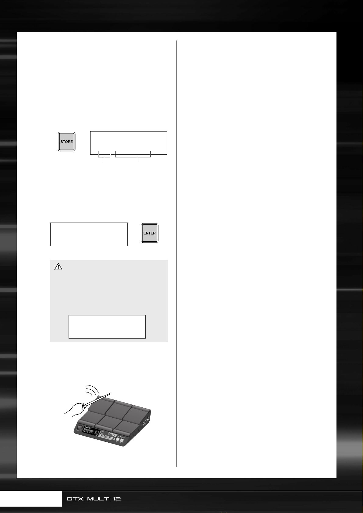
Importing Audio Files
Press the [KIT] button to return to the KIT
8
9
10
setting area.
Press the [STORE] button and store the
current kit and its new wave assignment as
a User kit.
As shown here, select an empty User kit using the [-/
DEC] and [+/INC] buttons, and then press the
[ENTER] button.
When asked to confirm that you want to
store the kit, press the [ENTER] button to
proceed.
VCE≥Store≥to
U001:User≥Kit
User kit number User kit name
11
≥≥≥KIT≥Store
≥Are≥you≥sure?≥≥
CAUTION
• The message ”Please keep power on...” will be displayed while data is being stored. It is very important
that the DTX-MULTI 12 is not turned off until this
message disappears. If the instrument were to be
turned off at this time, data for all User kits could be
permanently lost.
≥≥Please≥keep
≥≥power≥on...
To hear the imported wave, strike the
pad to which it was assigned.
26 Owner’s Manual
Page 27
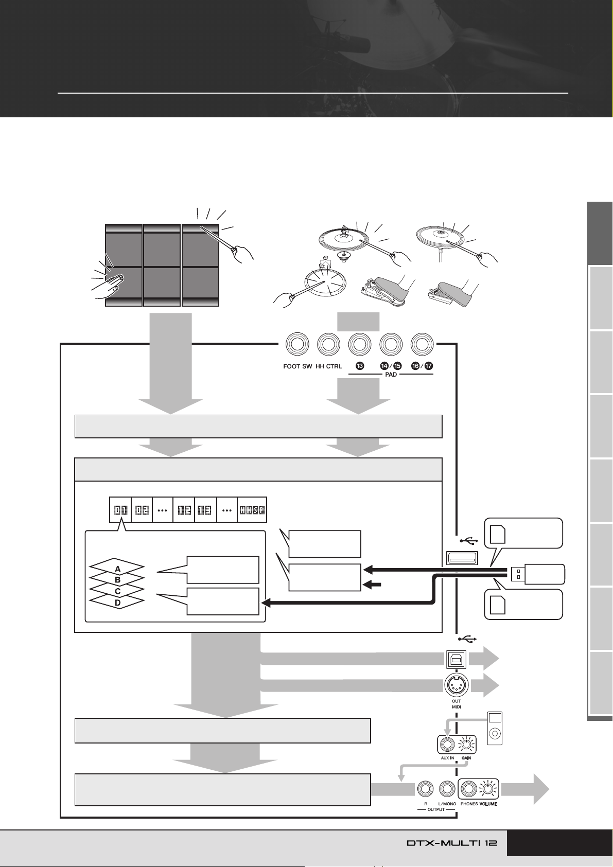
Reference
Internal Design
In this reference section, you will find a description of what takes place within the DTX-MULTI 12 between striking of a
pad and the output of a sound from speakers. Understanding how signals flow and are processed internally will allow
you to utilize the powerful functions of this versatile instrument to their maximum potential.
Functional Blocks
Built-in pads
Tr igger signals
Trigger setup (Preset or User)
Kit (Preset or User)
Makeup of each kit
Each pad has up to four layers (A to D) to
which voices can be assigned.
Preset
voices
Waves
External pads, controllers, and foot switches
PAD jacks
Tr igger Signals
Preset voices, patterns, and waves are
assigned to each of the built-in pads, external
pads, and external controllers.
Preset
patterns
Import
User patterns
Import
Pattern
recording
USB
TO DEVICE
SMF file
(Format 0)
WAV file
AIFF file
Signals for controlling the
internal tone generator
Internal tone generator
Reverb, chorus, variation, and master EQ.
MIDI messages
Effects
MIDI messages
MIDI messages
USB
TO HOST
MIDI output
Signals for controlling external tone
generators and
MIDI devices
TRIGGER ReferenceKITMIDI VOICEUTILITY WAVEPATTERN
Por table music
player, etc.
Audio output
Owner’s Manual 27
Page 28
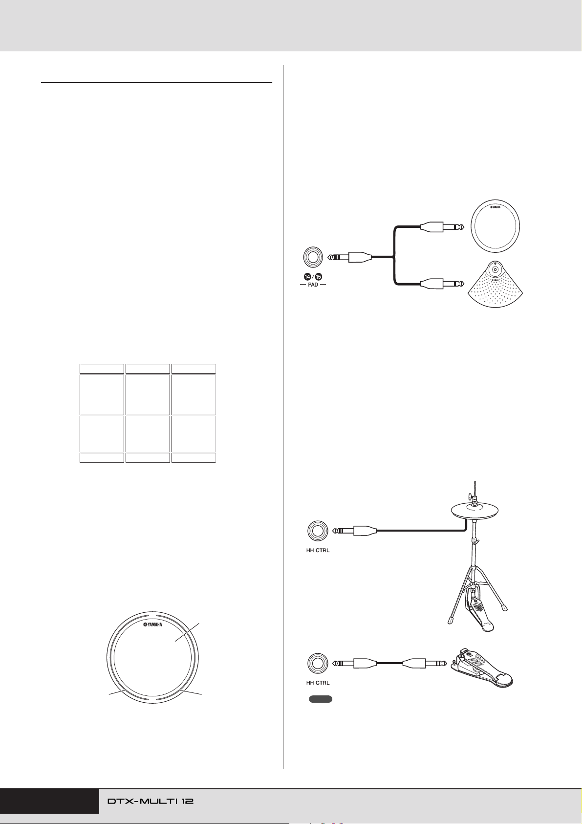
Internal Design
Pads & Trigger Signals
The DTX-MULTI 12 is played by striking any of the
twelve built-in pads and by striking and operating external
pads, foot switches, or other controllers connected via the
PAD jacks (M to Q), the HI-HAT CONTROL jack, and
the FOOT SW jack. Whenever you perform this type of
action, a trigger signal containing various items of performance data, such as the strength with which the pad was
struck, will be produced. These trigger signals are delivered to a tone generator, which outputs the appropriate
sound in response.
■ Built-in Pads (1 to 12)
As shown below, each of the DTX-MULTI 12’s built-in
pads is assigned a unique number between 1 and 12. On the
various parameter-setting pages used to configure the
instrument, these numbers are presented in the format
to as a means of identifying individual pads. Although
¡™
Pads 4 to 9 (main pads) and Pads 1 to 3 and 10 to 12 (rims)
are shaped differently, they all function in exactly the same
way. Whenever they are struck, the assigned voices, waves,
or patterns will be played.
º¡ º™ º£
º¢ º∞ º§
º¶ º• ºª
¡º ¡¡ ¡™
º¡
Although each features just one connector, the PAD N/O
and PAD P/Q jacks can be used to connect the mono outputs from a pair of pads. In this way, each of these jacks
can handle two different trigger signals. Within the display,
the numbers , , , and are used to identify
¡¢ ¡∞ ¡§ ¡¶
the corresponding pads.
Example:
Connecting a TP65 and a PCY65 via the PAD N/O jack
When a trigger signal produced by striking the
TP65 Single Zone Drum Pad is received, the
voices assigned to Pad are played.
When a trigger signal produced by striking the
PCY65 Single Zone Cymbal Pad is received, the
voices assigned to Pad are played.
¡¢
TP65
PCY65
¡∞
■ HI-HAT CONTROL Jack
The Hi-hat Control jack is used to connect an optional
RHH135 Two Zone Hi-Hat Pad (via its HH CTRL jack) or
an HH65 Hi-hat Controller (via its OUTPUT jack). As you
play the pad or controller, the DTX-MULTI 12 receives
and recognizes trigger signals for both hi-hat close and hihat splash*. Within the display, these signals are identified
as and , respectively.
∂∂œ› ∂∂‘á
* Hi-hat splash refers to the technique of producing sound by rapidly
depressing and releasing the hi-hat pedal.
■ PAD Jacks (M to Q)
The trigger-input jacks provided on the rear panel are used
to connect optional pads. Furthermore, the PAD M jack
can be used to connect a three-zone pad, which produces
three different types of trigger signal based on the position
at which it is struck. The DTX-MULTI 12 treats these
zones as three individual pads, identifying them on-screen
as , , and . For example, the three trig-
¡£ ¡£Ω¡ ¡£Ω™
ger signals output by a TP65S Three Zone Drum Pad are
identified as shown below.
Example: TP65S
A: Rim 1
¡£Ω¡
A: When a trigger signal from rim 1 is received, the voices assigned to
Pad are played.
¡£Ω¡
B: When a trigger signal from rim 2 is received, the voices assigned to
Pad are played.
¡£Ω™
C: When a trigger signal from the head is received, the voices assigned
to Pad are played.
¡£
C: Head
¡£
B: Rim 2
¡£Ω™
RHH135
HH65
NOTE
•Parameters related to hi-hats can be set on the various pages from the
UTILITY setting area’s HI-HAT section (UTIL5). (See page 89.)
28 Owner’s Manual
Page 29
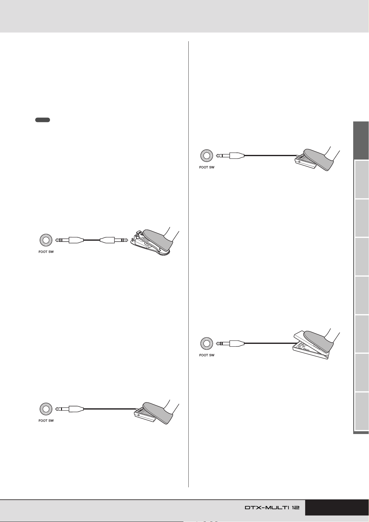
Internal Design
■ FOOT SW Jack
The Foot Switch jack is used to connect an optional hi-hat
controller (FC4 or FC5, etc.), hi-hat controller (HH65,
etc.), or foot controller (FC7) to the DTX-MULTI 12.
Within the instrument’s display, a signal input via this jack
is identified as .
Once you have told the DTX-MULTI 12 which type of
controller or foot switch is connected, you can then select
from a range of useful functions to assign to it. A number
of typical examples are described below.
NOTE
• Be sure to always turn off the DTX-MULTI 12 before connecting a controller
or foot switch. If you do not follow this precaution, the controller or foot
switch may not function correctly.
● Using an HH65 as a bass drum pedal
[Function]
With parameters configured as described below, an HH65
Hi-hat Controller can be used to play bass-drum voices and
the like. As with acoustic drums, furthermore, the tone of
the sound produced can be influenced by how fast or slow
you depress the controller. In addition, drum sounds can be
produced without the vibration and mechanical noise typical of acoustic bass-drum pedals.
√¤‘’
• Open the Select Voice page (VCE1) and choose a preset
voice, pattern, or wave to be assigned to . (See
page 56.)
● Changing kits or patterns using an FC4 or FC5
√¤‘’
[Function]
With parameters configured as described below, you can
use an FC4 or FC5 Foot Switch to change a range of different settings. For example, you could operate a foot switch
to select the next kit or pattern, to increase or decrease the
tempo by 1, to tap the tempo, or to turn the click-track on
or off. Furthermore, you can also set a MIDI Control
Change message number and value to be sent when the foot
switch is depressed.
FC4, FC5
[Setup]
• With the DTX-MULTI 12 turned off, connect the FC4 or
FC5 Foot Switch via the FOOT SW jack.
•Turn on the DTX-MULTI 12.
• On the Foot Switch Input page (UTIL4-2), set FootSwInSel to “ftSw”. (See page 89.)
• On the Pad Function page (UTIL4-1), select and
then set Func to the function you want to control using the
foot switch. (See page 88.)
√¤‘’
HH65
[Setup]
• With the DTX-MULTI 12 turned off, connect the HH65 Hihat Controller via the FOOT SW jack.
•Turn on the DTX-MULTI 12.
• On the Foot Switch Input page (UTIL4-2), set FootSwInSel to “HH65”. (See page 89.)
• On the Pad Function page (UTIL4-1), select and
then set Func to “off”. (See page 88.)
• Open the Select Voice page (VCE1) and choose a voice,
such as a bass drum, to be assigned to . (See
page 56.)
● Playing sounds using an FC4 or FC5
√¤‘’
√¤‘’
[Function]
With parameters configured as described below, you can
play sounds by operating an FC4 or FC5 Foot Switch. Trigger signals generated in this way have a fixed velocity, and
therefore, they are ideal for playing effect sounds, patterns,
and waves.
FC4, FC5
[Setup]
• With the DTX-MULTI 12 turned off, connect the FC4 or
FC5 Foot Switch via the FOOT SW jack.
•Turn on the DTX-MULTI 12.
• On the Foot Switch Input page (UTIL4-2), set FootSwInSel to “ftSw”. (See page 89.)
• On the Pad Function page (UTIL4-1), select and
then set Func to “off”. (See page 88.)
√¤‘’
● Adjusting volume (or other MIDI Control
Change values) using an FC7
[Function]
With parameters configured as described below, you can
adjust volume and many other MIDI Control Change values by changing the pedal angle of an FC7 Foot Controller
(in order to send MIDI Control Change messages). The
FC7 retains its current pedal angle after you remove your
foot, and therefore, it is ideal for making minute changes to
the controlled parameter.
FC7
[Setup]
• With the DTX-MULTI 12 turned off, connect the FC7 Foot
Controller via the FOOT SW jack.
•Turn on the DTX-MULTI 12.
• On the Foot Switch Input page (UTIL4-2), set FootSwInSel to “FC7”. (See page 89.)
• On the Pad Function page (UTIL4-1), select and
then set Func to the MIDI Control Change message
(“CC01” to “CC95”) that you want to control. (See page
88.)
√¤‘’
TRIGGER ReferenceKITMIDI VOICEUTILITY WAVEPATTERN
Owner’s Manual 29
Page 30
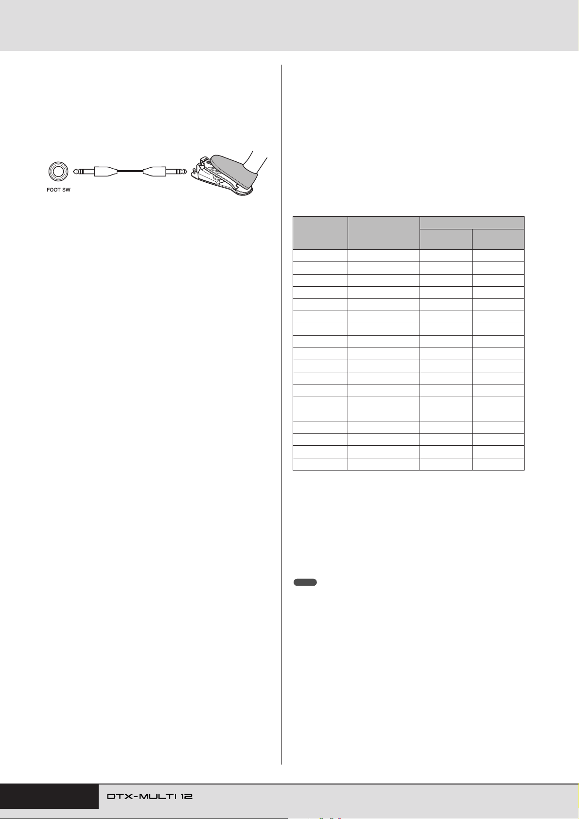
Internal Design
● Adjusting volume and other parameters using an
HH65
[Function]
In the same way as with an FC7 Foot Controller, you can
adjust volume and a wide range of MIDI Control Change
values by adjusting the degree by which an HH65 Hi-hat
Controller is operated.
HH65
[Setup]
• With the DTX-MULTI 12 turned off, connect the HH65 Hi-
hat Controller via the FOOT SW jack.
•Turn on the DTX-MULTI 12.
• On the Foot Switch Input page (UTIL4-2), set FootSwIn-
Sel to “HH65”. (See page 89.)
• On the Pad Function page (UTIL4-1), select and
√¤‘’
then set Func to the MIDI Control Change message
(“CC01” to “CC95”) that you want to control. (See page
88.)
■ Using Acoustic Drums to Produce Trigger
Signals
Optional drum triggers, such as the DT10 or DT20, can be
used to convert performances on acoustic drums into trigger signals and to input these signals into the instrument.
You can even apply drum triggers to training pads in order
to produce trigger signals.
■ Trigger Setups
Settings for all of the parameters associated with pad sensitivity are collectively referred to as a “trigger setup”. In
addition to the actual sensitivity of the pad when it is
struck, a trigger setup can also include parameter settings
intended to prevent a pair of trigger signals being produced
in response to a single strike (i.e., double triggering) and
unwanted trigger signals being produced by pads other
than the one that was struck (i.e., crosstalk). The DTXMULTI 12 supports many different playing styles using
sticks and hands, and by selecting the most appropriate
trigger setup for the style being used, you can ensure that
trigger signals will be correctly processed. Trigger setups
can also be adjusted in order to ensure that trigger signals
from external pads and controllers are processed in an ideal
manner.
Your DTX-MULTI 12 comes pre-loaded with five Preset
trigger setups suitable for many different needs, and you
can also create up to ten unique User trigger setups to suit
your own individual requirements.
■ Using Optional Pads & Drum Triggers with
the PAD Jacks
Whenever you are using separately-sold pads and/or drum
triggers, the types of trigger signal handled will depend on
which of the PAD jacks is used for connection. The following table shows how optional pads and drum triggers will
operate when connected via the various PAD jacks on the
rear panel.
PAD M: Suitable for use with two-zone and three-zone pads. Not
suitable for pad controllers.
PAD N/O, PAD P/Q: Not suitable for two-zone pads, threezone pads, or pad controllers.
Input (PAD jacks)
Model Product name
TP65 Drum Pad C C
TP65S Drum Pad A C
TP100 Drum Pad A C
TP120SD Snare Pad B C
RHH130 Hi-hat Pad B C
RHH135 Hi-hat Pad B C
PCY65 Cymbal Pad C C
PCY65S Cymbal Pad B C
PCY130 Cymbal Pad C C
PCY130S Cymbal Pad B C
PCY130SC Cymbal Pad A C
PCY135 Cymbal Pad A C
PCY150S Cymbal Pad A C
PCY155 Cymbal Pad A C
KP65 Kick Pad C C
KP125 Kick Pad C C
DT10 Drum Trigger C C
DT20 Drum Trigger C C
A: Operates as a three-zone pad.
If using a compatible product from the TP series, voices assigned to
each of the two rim sections and the head section can be played. If
using a compatible product from the PCY series, voices assigned to
each of the bow, edge, and cup sections can be played.
B: Operates as a two-zone pad.
If using a compatible product from the RHH series, voices assigned
to each of the bow and edge sections can be played. If using a compatible product from the PCY series, voices assigned to each of the
bow and edge sections can be played.
C: Operates as a monoaural pad.
NOTE
•For the most up-to-date information on support for optional pads and drum
triggers, visit the following web page.
http://www.yamaha.co.jp/english/product/drums/ed/
PAD M
PAD N/O
PAD P/Q
30 Owner’s Manual
Page 31
Internal Design
Sounds Produced Using the Pads
Whenever the internal tone generator receives a trigger signal produced by striking a pad or by operating a controller
or foot switch, it will play a voice assigned to that pad, controller, or foot switch. As described below, three different
types of voice are available for assigning – namely, preset
voices, patterns, and waves.
• Preset voices
Drum sounds such as snares, bass drums, and cymbals;
percussion sounds; and pitched-instrument sounds such
as piano, xylophone, and guitar.
• Patterns
One-shot or looped phrases containing performance data
for a range of different instruments.
• Waves
Audio files imported into the DTX-MULTI 12 from a
variety of sources.
To assign a voice to a pad, controller, or foot switch, access
the VOICE setting area’s Select Voice page (VCE1) by
pressing the [VOICE] button (and if necessary, the [B]
button). On this page, voices are categorized by instrument
type (in the case of preset voices), as patterns, or as waves.
While preset voices, patterns, and waves can all be
assigned to pads in the same way, it is important to remember that each voice type plays in a different way and is configured using different parameters.
■ Preset Voices
As an electronic percussion instrument played by striking
pads, the DTX-MULTI 12 comes preloaded with a vast
library of drum sounds, such as snares, bass drums, and
cymbals, together with a broad spectrum of percussioninstrument sounds. Also included are many pitched instruments, such as piano, xylophone, and guitar. The term “preset voices” is used to refer to these built-in drum and
instrument sounds.
Drum and percussion voices from this preset-voice collection are not rooted at one specific pitch; instead, you can
intuitively adjust their tuning in order to match the sounds
of other instruments. Meanwhile, pitched-instrument
voices such as piano and guitar can be assigned to pads
with a specific pitch setting, thus allowing you to play several different notes together to produce chords, or with
voices at different semitones assigned to the twelve pads, to
freely play melodic parts. With the timing and strength of
your playing reflected in the sound produced by preset
voices, you can perform with practically the same level of
expressiveness as afforded by acoustic instruments.
■ Patterns
The DTX-MULTI 12 can also play rhythmic or melodic
phrases known as “patterns”. Capable of reproducing the
sound of performances on many different instruments, each
pattern can be up to several measures in length. In the same
way as snare sounds are produced by striking a pad to
which a snare voice has been assigned, you can start and
stop the playback of a pattern by striking the pad to which
it is assigned. In effect, pads with pattern assignments operate as start/stop switches whenever struck (regardless of
how hard or soft they are actually struck). Your DTXMULTI 12 comes pre-loaded with 128 Preset patterns
(including 3 demo patterns) containing performance data
from a host of different instrument genres, and by assigning these freely to pads, you can easily create your own
unique kits. For even more flexibility, you can also record
your own performances and even import standard MIDI
files (Format 0) to create up to 50 additional User patterns.
■ Waves
The DTX-MULTI 12 is fully equipped to playback audio
files that can be created, edited, and played on computers.
Commonly called “samples” or “sample data”, these files
contain short portions of sound, and once imported into the
DTX-MULTI 12, they are referred to as “waves”. Either
WAV or AIFF type audio files can be imported into the
instrument’s internal wave memory and assigned to pads in
much the same way as preset voices and patterns. You can
also edit imported waves.
As audio files imported into the instrument’s wave memory
are assigned to pads as a single voice much like preset
voices and patterns, the term “wave data” is used within
this manual in the same way as “preset voice data” or “pattern data”. In contrast, the term “wave file” is used to refer
to data that has not yet been imported and is handled in the
form of a file on a computer, sampler, or USB memory
device.
TRIGGER ReferenceKITMIDI VOICEUTILITY WAVEPATTERN
Owner’s Manual 31
Page 32
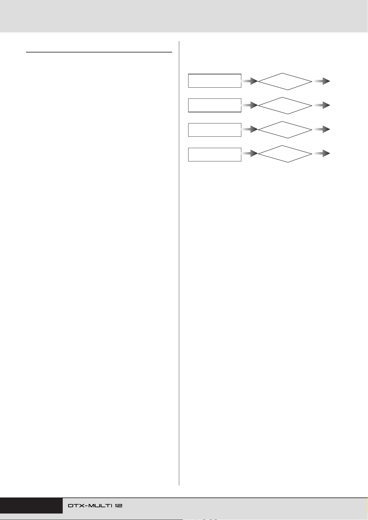
Internal Design
Kit Makeup
The term “kit” is used to refer to a collection of preset
voices, patterns, and waves assigned to each of the instrument’s built-in pads (1 to 12) and to any external pads, foot
switches, or controllers connected via the PAD jacks (M to
Q), the FOOT SW jack, and the HI-HAT CONTROL jack.
For added convenience, the instrument comes pre-loaded
with 30 different Preset kits. You are, however, free to make
your own unique kits in whatever way you see fit, and up to
200 of these User kits can also be stored internally.
■ Kits & Voices
Within the DTX-MULTI 12, voice data is grouped and
stored in kit units. In other words, each kit contains the
voice-related information for all of its pad and controller
assignments. Whenever a User kit is created by editing
voices, the voices themselves are not stored within the kit;
instead, the settings for all associated parameters – such as
tuning, stereo pan, attack time, release time, effects, etc. –
are stored. As you would expect, each of the pads can have
different parameter settings. Therefore, even when the
Select Voice page shows the same voice assigned to two or
more pads, the sounds produced by each will not necessarily be the same.
■ Voice Layers
Using the DTX-MULTI 12’s Layer function, you can
assign a number of different voices to a single pad or external controller. Specifically, this instrument allows up to
four layers (A to D) to be setup per pad, meaning that each
pad can play as many as four different voices. These layered voices can also be triggered in a number of different
ways – for example, they will all play together in Stack
mode, a different one will be played for each strike in
Alternate mode, and they can be sustained and turned off
on each successive strike in Hold mode. In order that the
Layer function may be put to use, the pad in question must
first be setup to send multiple MIDI messages whenever
struck. Then, voices are assigned to each of the layers, and
a layer playing mode is specified for the pad. For more
details, refer to the section Specifying MIDI note numbers
and assigning voices to each on page 34.
Arrangement of Voice Layers
When Pad 1 is struck, layers A through
Layer A
VCE1 -º¡- ç
GM001:GrandPiano
Layer B
VCE1 -º¡- ¬
GM025:NylonGtr
Layer C
VCE1 -º¡- œ
GM041:Violin
Layer D
VCE1 -º¡- ˚
GM051:SynthStr1
D are all played simultaneously.
GM001:GrandPiano
GM025:NylonGtr
GM041:Violin
GM051:SynthStr1
■ Information Contained in Kits
Three different setting areas apply specifically to kits: In
the KIT setting area, you can specify a volume, configure
effects, and set other parameters affecting the entire kit; in
the VOICE setting area, you can assign preset voices, patterns, and waves to each pad, foot switch, and controller,
and you can also set parameters such as tuning and volume
for each of the assigned voices; and in the MIDI setting
area, you can set MIDI-related parameters affecting the kit
or individual pads and controllers. Setting a preset voice,
pattern, or wave to be played when a pad is struck involves
the following two steps.
1. Indication of the MIDI note number(s) to be sent
when a specific pad is struck. (MIDI setting area)
2. Indication of the preset voice, pattern, or wave to be
played for each MIDI note number. (VOICE setting
area)
In cases where only a single layer is setup for a pad, however, it is possible to omit Step 1 above. (The required setting will be performed automatically when you select a
voice in Step 2.)
The following two methods of allocating voices are
described below.
• Assigning a voice directly to a pad
• Specifying MIDI note numbers and assigning voices
to each
32 Owner’s Manual
Page 33
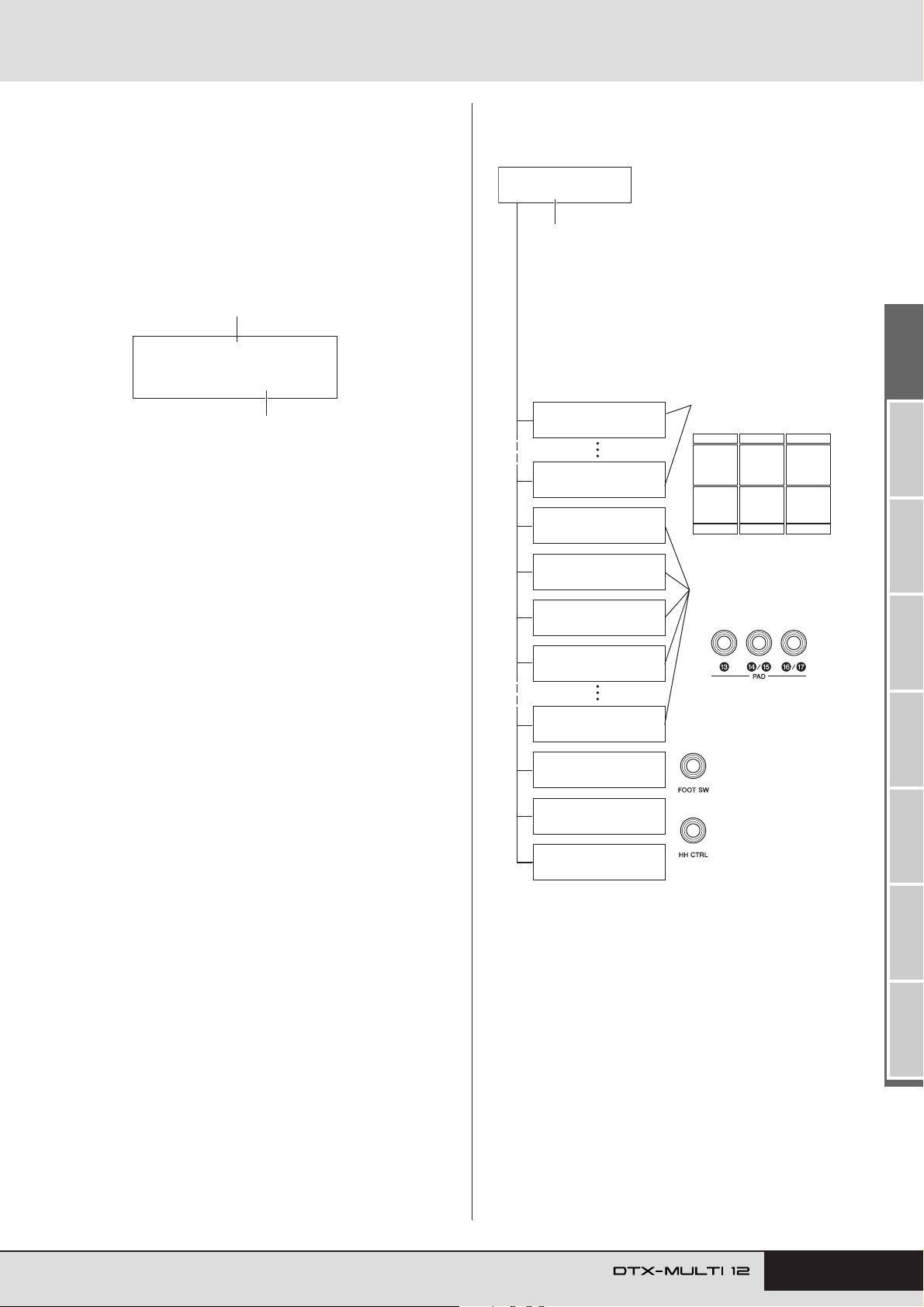
Internal Design
● Assigning a voice directly to a pad
In order to assign a voice directly to a pad, we first select
the pad to be set, and then choose the required preset voice,
pattern, or wave.
To start, press the [KIT] button to access the KIT setting
1
area. On the Select Kit page (KIT1), select the kit to be
set. Next, press the [VOICE] button to access the VOICE
setting area and navigate to the Select Voice page
(VCE1).
Pad or controller being set
VCE1≥≥-º¡Cy013:Thin16Eg
Voice assigned to the pad or controller
Move the flashing cursor to the upper row of text, and
2
using the [-/DEC] and [+/INC] buttons, select the pad or
controller you want to set. You can also select a pad by
striking it. The lower row of text will show the voice (i.e.,
a preset voice, pattern, or wave) currently assigned to
the selected pad or controller. Move the flashing cursor
down to the lower row of text, and using the [-/DEC] and
[+/INC] buttons, select the new voice to be assigned.
By repeating this process to assign preset voices, patterns, and waves to all pads and controllers, you can
quickly and conveniently setup your own personalized
drum kit. Furthermore, parameters such as volume, tuning, stereo pan, and effect levels can be set for the
voices assigned to the various pads and controllers.
Once you have finished configuring a kit in this way, you
3
can store it as one of the instrument’s User kits.
Example: Working with Preset kit 1
KIT setting area
KIT1
P009:Oak≥Custom
Kit name
VOICE setting area
VCE1≥≥-º¡Cy013:Thin16Eg
VCE1≥≥-¡™-≥≥≥≥≥ç
HH005:Brite≥Op
VCE1≥≥-¡£Sn001:Oak≥Custom
VCE1≥≥-¡£Ω¡Sn002:OakCtmOpRm
VCE1≥≥-¡£Ω™Sn003:OakCtmClRm
VCE1≥≥-¡¢Kk001:OakCtm22
VCE1≥≥-¡¶-≥≥≥≥≥ç
HH006:Brite≥EgOp
VCE1≥≥-√¤‘’-
-----:----------
VCE1≥≥-∂∂œ›HH003:Brite≥FtCl
VCE1≥≥-∂∂‘áHH004:Brite≥FtOp
Settings made in KIT setting area
•Volume of the entire kit
• Kit tempo
•Effect settings for the entire kit
• Muting
• Hi-hat settings
etc.
Assigning voices to built-in
pads 1 to 12.
Assigning voices to pads
connected via the PAD
jacks
M
to Q.
Assigning a voice* to a
controller or foot
switch connected via
the FOOT SW jack.
Assigning a voice* to a
controller connected
via the HI-HAT CONTROL jack.
Settings made in VOICE
setting area
•Volume of each pad (or layer)
•Tuning of each pad
• Stereo pan of each pad
•Effect settings for each pad
etc.
*: Voices cannot be assigned to
any controller or foot switch
already having a function
assigned on the Pad Function page (UTIL4-1).
TRIGGER ReferenceKITMIDI VOICEUTILITY WAVEPATTERN
Owner’s Manual 33
Page 34
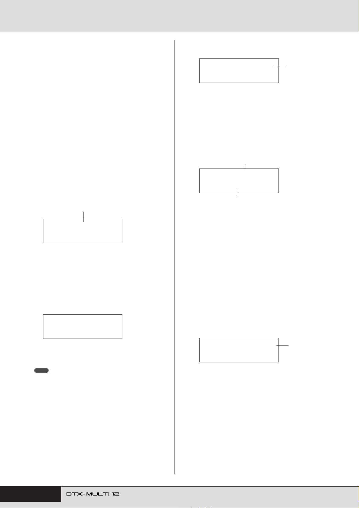
Internal Design
● Specifying MIDI note numbers and assigning
voices to each
The second approach to configuring a pad involves setting
one or more MIDI note numbers to be sent whenever the
pad is struck and then telling the internal tone generator
which voices to play when MIDI notes with these numbers
are received. In contrast to the direct approach described
above, this method allows multiple MIDI Note messages to
be sent from a single pad in order to play layered or alternating voices using the Layer function. In addition, these
MIDI Note messages can also be output via the MIDI OUT
connector or USB TO HOST port in order to control
another MIDI instrument.
In the following example, we will setup built-in Pad 1 to
play two different voices simultaneously when it is struck.
Press the [KIT] button to access the KIT setting area. On
1
the Select Kit page (KIT1), select the kit to be set.
Press the [MIDI] button to access the MIDI setting area
2
and navigate to the Select Message Type page (MIDI1).
Pad
MIDI1≥-º¡MessageType=note
Press the [CC
4
(MIDI1-2).
CC
] button to navigate to the MIDI Note page
MIDI1-2≥-º¡-≥≥≥ç
Layer
Note=≥≥≥D≥1/≥38
On this page, we can set the MIDI notes to be sent by
the pad. Specifically, the Note parameter on the lower
row of text is used to set a MIDI note number, while the
indicator in the top right corner shows which of the
pad’s four layers (A to D) is being set. For now, select
“D1/38” as the MIDI note to be sent by Layer A.
Press the [VOICE] button to access the VOICE setting
5
area and navigate to the Select Voice page (VCE1).
MIDI note number
VCE1≥≥≥D≥1/≥38
Sn001:OakCustom
Assigned voice
On the upper row of text, use the [-/DEC] and [+/INC]
buttons to select “D1/38” – that is, the MIDI note number that Layer A of Pad 1 will send. On the lower row of
text, set “Sn001:OakCustom” as the voice to be played
for that MIDI note number.
In the upper row of text, select “ ” as the pad to
be set. Following this, move the flashing cursor to the
lower row of text and set the MessageType parameter to
“note” (indicating that a MIDI Note message will be
sent when the pad is struck).
Press the [ENTER] button to open the Playing Mode
3
page (MIDI1-1).
-º¡-
MIDI1-1≥-º¡≥Mode=stack
In the lower row of text, set the Mode parameter to
“stack” (indicating that all MIDI notes assigned to the
pad will be played simultaneously).
NOTE
• In addition to “stack”, you can also set the Mode parameter to “alternate”, which causes the notes assigned to the pad to play individually
in turn each time it is struck, or “hold”, which causes the notes to be
alternately turned on and off each time the pad is struck. (See page
62.)
With the settings now made, a MIDI note with MIDI note
number 38 (i.e., D1) will be sent to the internal tone generator whenever Pad 1 is struck, and the tone generator will
respond by playing the preset voice Sn001 (OakCustom).
Next, we will setup Pad 1 to also send the MIDI note number 40 (E1) whenever struck, and we will tell the internal
tone generator to play the preset voice Cy013 (Thin16Eg)
in response.
Press the [MIDI] button to access the MIDI setting area
6
and navigate to the MIDI Note page (MIDI1-2).
MIDI1-2≥-º¡-≥≥≥¬
Layer
Note=≥≥≥E≥1/≥40
Move the flashing cursor to the “ ” indicator in the top
right corner, and using the [+/INC] button, change this
to “ ”. Move back to the lower row of text, and set
¬
“E1/40” as the MIDI note number to be sent by Layer
B.
ç
34 Owner’s Manual
Page 35
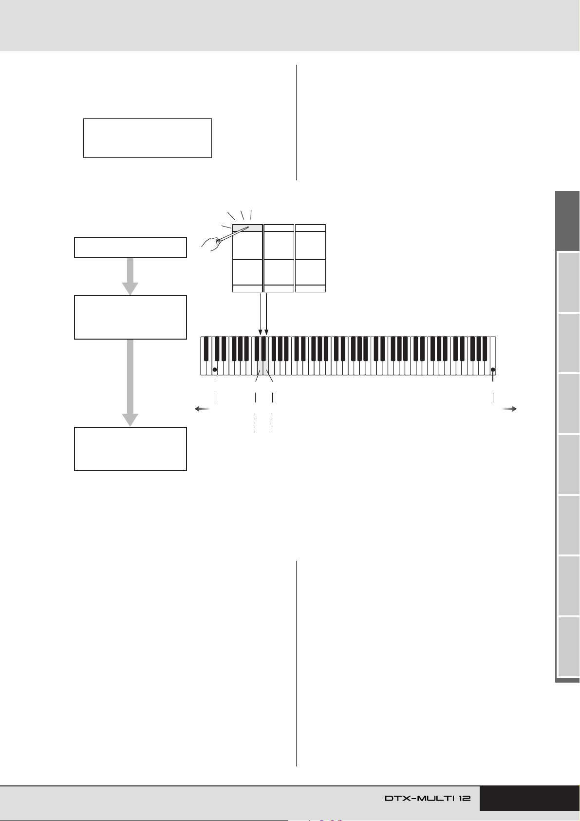
Internal Design
Press the [VOICE] button, navigate to the Select Voice
7
page (VCE1), and in the same way as described above,
set “Cy013:Thin16Eg” as the voice to be played for MIDI
notes with the MIDI note number 40 (E1).
VCE1≥≥≥≥E≥1/≥40
Cy013:Thin16Eg
Built-in Pad 1 is struck.
Two MIDI notes (“D1/38”
and “E1/40”) are simulta-
neously sent to the internal
tone generator.
With your DTX-MULTI 12 configured in this way, whenever you strike built-in Pad 1, two MIDI notes with the
MIDI note numbers 38 (D1) and 40 (E1) will be simultaneously sent to the internal tone generator, and the tone
generator will respond by playing the preset voices Sn001
(OakCustom) and Cy013 (Thin16Eg) together.
The following diagram illustrates exactly what happens
inside the instrument when Pad 1 has been setup to play
two voices simultaneously as described above.
MIDI note numbers on a standard keyboard.
The voices assigned to
each of these MIDI notes
are played.
C0
240
Sn001: OakCustom
D1
38
snare sound
E1
40
Cy013: Thin16Eg
cymbal sound
■ Using the DTX-MULTI 12 as a MIDI Controller
Instead of MIDI Note messages, the DTX-MULTI 12 can
be setup to send MIDI Program Change messages, MIDI
Control Change messages, and the like to MIDI devices
connected via the MIDI OUT connector or USB TO HOST
port whenever pads are struck or external controllers are
operated. Using this functionality, you can easily configure
pads to, for example, start and stop playback on a MIDI
sequencer or to change presets on a MIDI instrument.
C7
108 127
In contrast to the type of control introduced in the Pads &
Trigger Signals section (see page 28), which makes it possible to play the DTX-MULTI 12 with trigger signals sent
from a controller or foot switch connected via the FOOT
SW jack, the MIDI control function allows the instrument’s
built-in pads and external pads to operate as versatile MIDI
controllers. In addition to selecting frequently-used kits
and patterns or setting the tempo for click-track or pattern
playback, this powerful function also allows you to assign
MIDI Control Change numbers (01 to 95) and values to
pads in order to facilitate a wide range of unique modes of
use.
TRIGGER ReferenceKITMIDI VOICEUTILITY WAVEPATTERN
Owner’s Manual 35
Page 36
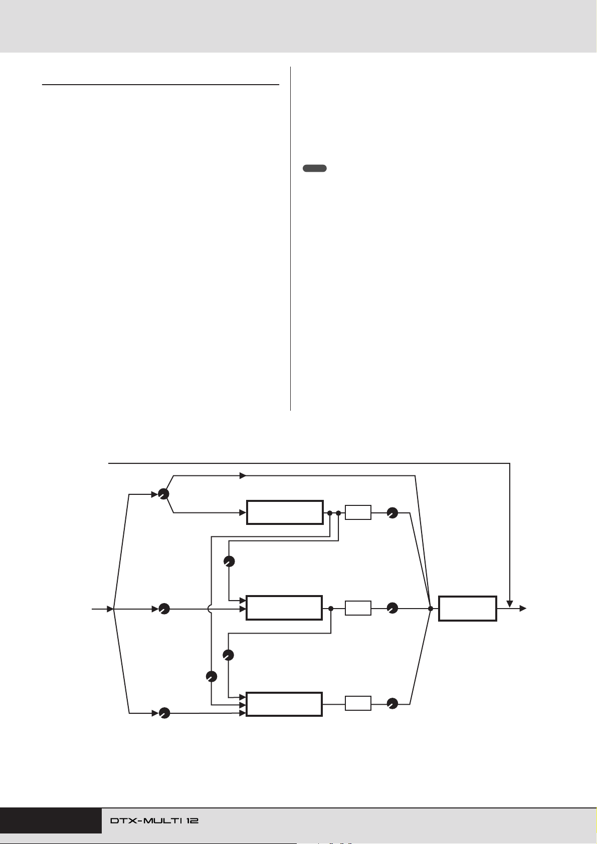
Internal Design
Effects
The effect processor built into your DTX-MULTI 12
applies special audio effects to the output from the tone
generator in order to modify and enhance its sound in a
wide variety of ways. Normally applied during the final
stages of editing, such effects allow you to optimize the
sound in line with your own specific requirements.
■ Effect Processor Structure
This instrument can apply effects to the tone generator’s
output using the following four effect units.
● Variation
Variation effects allow you to sculpt your sound in a variety
of different ways. A specific type of variation effect can be
selected for each kit within the VARIATION section
(KIT4); furthermore, you can also specify the degree to
which this effect is applied to each layer on the Variation
Send page (VCE4-1).
● Chorus
Chorus effects change the spatial characteristics of the
sounds to which they are applied. A specific type of chorus
effect can be selected for each kit within the CHORUS section (KIT5); furthermore, you can also specify the degree
to which this effect is applied to each layer on the Chorus
Send page (VCE4-2).
● Reverb
Reverb effects add a warm ambience to sounds, simulating
the complex reflections of actual performance spaces, such
as a concert hall or a small club. A specific type of reverb
can be selected for each kit within the REVERB section
(KIT6); furthermore, you can also specify the degree to
which this effect is applied to each layer on the Reverb
Send page (VCE4-3).
NOTE
• The degree to which User patterns are processed by these effect units can
be specified on the Variation Send page (PTN3-5), the Chorus Send page
(PTN3-6), and the Reverb Send page (PTN3-7); furthermore, these settings can then be saved as part of the User pattern data.
● Master EQ
Processing the overall instrument sound just before output,
the Master EQ supports five-band equalization. As this
equalization is applied to the sound of the entire instrument
and not that of individual drum kits or voices, Master EQ
settings do not change whenever a new drum kit is selected.
To set the corresponding parameters, use the parameter-setting pages from the UTILITY setting area’s MASTER EQ
section (UTIL3).
■ Effect Connection
AUX IN
VCE4-1
MIDI3-5
Var(Dry)
Dry signal
*1
*2
KIT3-1
VCE4-2
MIDI3-6
ChorusSend
VarToRev
KIT3-2
VCE4-3
MIDI3-7
ReverbSend
(Dry line)
(Wet line)
KIT4-4
KIT4-5
VarToCho
KIT5-4
ChoToRev
KIT4
VARIATION
VARIATION
KIT5
CHORUS
CHORUS
KIT6
REVERB
REVERB
*1: Click-track voices cannot be sent to effects.
*2: On the Variation Send page (VCE4-1), you can set the required balance
between the amount of the signal that will bypass the effect (i.e., the dry
level) and the amount that will be sent to the effect (i.e., the wet level).
*3: Master EQ is not applied to the headphone output.
*4: External audio signals (AUX IN) bypass all effects.
KIT4-3
VarPan
Pan
KIT5-3
ChoPan
Pan
KIT6-3
RevPan
Pan
KIT4-2
VarReturn
KIT5-2
ChoReturn
KIT6-2
RevReturn
UTIL3
MASTER EQ
Master EQ
*3
*4
36 Owner’s Manual
Page 37
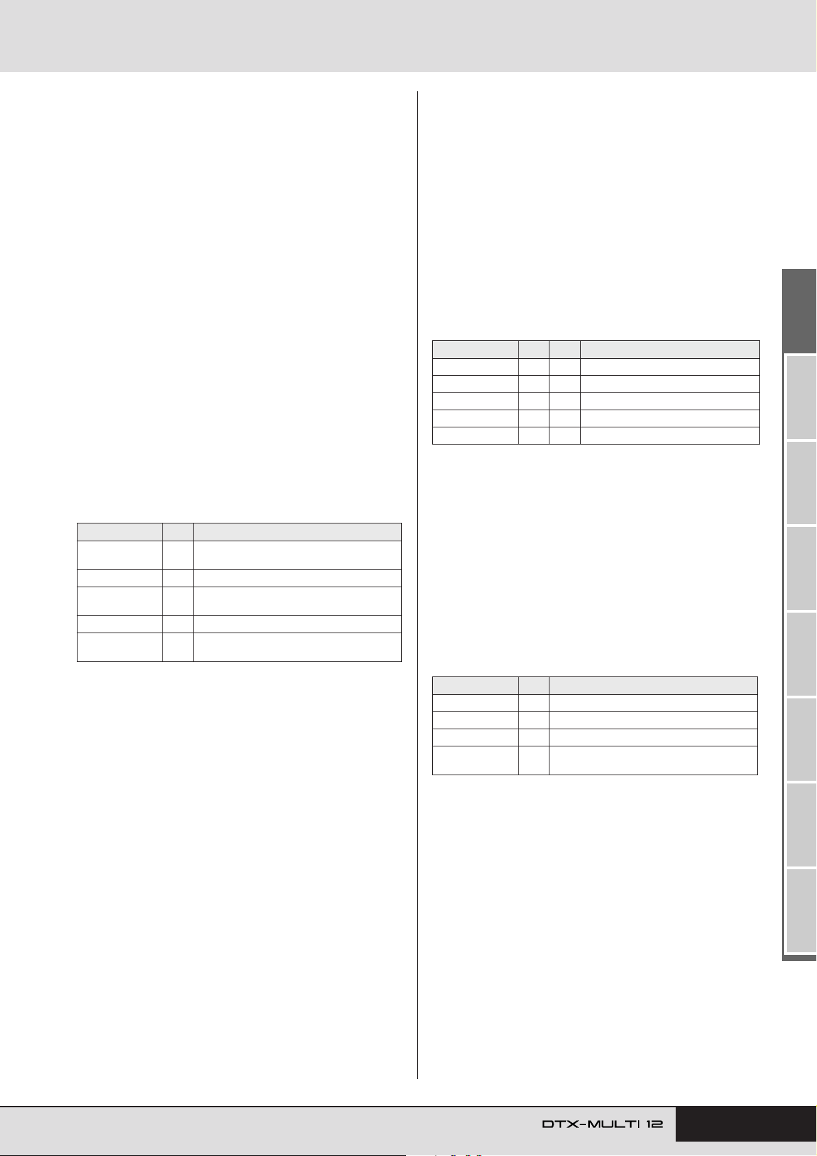
Internal Design
■ Effects & Effect Categories
The various individual effects provided by this instrument’s
effect units are sorted into a number of different categories.
What follows is a description of each category and the
effects it contains. We recommend that you refer to these
descriptions whenever setting effects. Each category’s
effect table indicates which of the effect units – i.e., Reverb
(Rev), Chorus (Cho), or Variation (Var) – can be used to
apply the effect in question. Any effect marked using a
symbol can be selected and modified on the corresponding
effect unit’s parameter setting pages.
● Compressor & EQ
The compressor is an effect commonly used to limit and
compress the dynamics (i.e., softness or loudness) of an
audio signal. In the case of vocals, guitar parts, and other
signals that have widely varying dynamics, this effect
essentially squeezes the dynamic range, making soft
sounds louder and loud sounds softer. Furthermore, a compressor’s attack and decay characteristics can be adjusted
to modify how punchy or sustained an audio signal sounds.
Multi-band compression, meanwhile, splits the input into
three different frequency bands for processing independently of each other; accordingly, this type of effect can be
thought of as combining compression with equalization.
Effect Type Va r Description
Compressor ✓
MltBndComp ✓ Three-band compressor.
3 Band EQ ✓
Vintage EQ ✓ Vintage five-band parametric equalizer.
Enhancer ✓
Relatively fast-acting compressor well
suited to solo performances.
Three-band compressor also featuring
equalization.
Adds higher-order harmonics to enhance a
sound’s presence.
✓
● Flanger & Phaser
A flanger creates a swirling, metallic sound, similar to that
of a jet plane. While this effect operates using the same
basic principles as chorus effects, it uses shorter delay
times and also incorporates feedback to produce a very distinctive swelling sound. Rather than being used constantly
throughout a song, it is more suited to selective use in specific sections in order to add variety. A phaser, meanwhile,
introduces a phase shift into the sound being processed
before returning it to the effect input using a feedback circuit in order to produce a characteristic animated yet mellow tone. Gentler overall than a flanger, this effect can be
put to use in a wider range of situations, and for example, is
often used with electric pianos to sweeten their sound in a
variety of ways.
Effect Type Cho Va r Description
SPX Flanger ✓✓Produces a swirling, metallic sound.
TempoFlanger ✓✓Tempo-synchronized flanger.
PhaserMono – ✓ Vintage sounding mono phaser.
PhaserStereo – ✓ Vintage sounding stereo phaser.
TempoPhaser – ✓ Tempo-synchronized phaser.
● Distortion
As its name suggests, a distortion effect distorts the sound
fed into it. It produces a sound similar to that of an amplifier turned up too high or fed with a signal that is already
sufficiently loud. This type of effect is widely used to add a
harsh, biting edge; furthermore, the resultant sound is characterized by overall thickness and long sustain times. This
thickness comes from the large numbers of harmonics contained within clipped signals. Meanwhile, the longer sustain is not produced by the original sound being stretched;
rather, it is produced when the slowly-fading release portion that cannot normally heard is amplified and distorted.
Effect Type Va r Description
AmpSim 1 ✓ Guitar amp simulation.
AmpSim 2 ✓ Guitar amp simulation.
CompDist ✓ Combines compression and distortion.
CompDistDly ✓
Combines compression, distortion, and
delay.
Owner’s Manual 37
TRIGGER ReferenceKITMIDI VOICEUTILITY WAVEPATTERN
Page 38
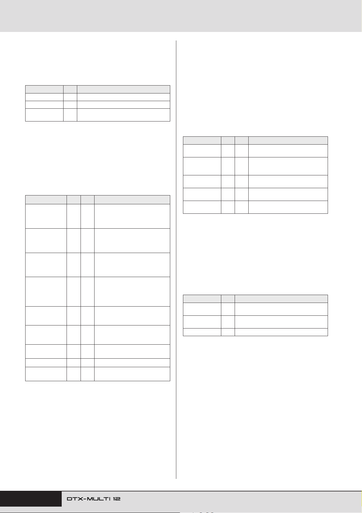
Internal Design
● Wah
A wah effect dynamically changes the frequency characteristic of a filter in order to produce a highly unique filtersweep sound. Auto wah changes the frequency in a cyclic
manner using an LFO, while touch wah performs filter
sweeps in response to the volume of the input signal.
Effect Type VAR Description
AutoWah ✓ Vintage automatic wah effect.
TouchWah ✓ Classic volume-responsive wah effect.
TouchWahDist ✓
Touch wah with distortion applied at the output.
● Reverb
Reverb effects model the complex reverberation produced
by sounds within enclosed spaces. In this way, they add a
natural-sounding sustain, which produces a feeling of
depth and space. Furthermore, different types of reverb –
such as hall, room, plate, and stage – can be used to simulate the sound of acoustic environments of varying sizes
and constructions.
Effect Type Rev Var Description
Emulation of hall acoustics using an
SPX Hall ✓✓
SPX Room ✓✓
SPX Stage ✓✓
R3 Hall ✓ –
R3 Room ✓ –
R3 Plate ✓ –
EarlyRef – ✓
GateReverb – ✓ Simulation of gated reverb.
ReverseGate – ✓
algorithm derived from the classic
Yamaha SPX1000 Digital MultiEffects Processor.
Emulation of room acoustics using
an algorithm derived from the classic Yamaha SPX1000 Digital MultiEffects Processor.
Emulation of stage acoustics using
an algorithm derived from the classic Yamaha SPX1000 Digital MultiEffects Processor.
Emulation of the acoustics of a concert hall using an algorithm derived
from the Yamaha ProR3 – a digital
reverberator for professional-audio
applications.
Emulation of room acoustics using
an algorithm derived from the
above-mentioned Yamaha ProR3.
Emulation of plate reverb using an
algorithm derived from the abovementioned Yamaha ProR3.
Early reflections without any subsequent reverberation.
Simulation of gated reverb played in
reverse.
● Chorus
Chorus reproduces the sound of multiple instruments playing in unison for a thicker, deeper tone. As all instruments
differ slightly from each other in terms of pitch and phase,
their playing together produces an overall sound that is
warmer and more spacious. In order to reproduce this type
of behavior, chorus effects make use of delay. Specifically,
a delayed, second version of the original signal is produced
and given a vibrato-type effect by varying its delay time
over a period of approximately one second using an LFO.
When this second version is mixed back into the original
signal, the resulting tone sounds as if multiple instruments
are being played in unison.
Effect Type Va r Cho Description
G Chorus ✓✓
2 Modulator ✓✓
SPX Chorus ✓✓
Symphonic ✓✓
Ensemble – ✓
Rich, deep chorus with complex modulation.
Chorus effect allowing pitch and
amplitude modulation to be adjusted
for a more natural, spacious tone.
Enhances modulation and spaciousness using a 3-phase LFO.
Multi-stage modulation for a widersounding chorus.
Modulation-free chorus achieved by
adding a slightly pitch-shifted sound.
● Tremolo & Rotary
Tremolo effects are characterized by the way in which they
modulate volume in a cyclical fashion. An auto-pan effect,
meanwhile, moves the sound from left to right in a similar
cyclical manner, and a rotary speaker effect simulates the
distinctive vibrato of rotary-type speakers often used with
organs. In a rotary speaker, the horn and rotor are spun in
order to create highly unique sounds using the Doppler
Effect.
Effect Type Va r Description
AutoPan ✓
Tremolo ✓
RotarySp ✓ Rotary speaker simulator.
Cyclically moves the sound between left and
right channels.
Cyclically modulates the volume of the processed signal.
38 Owner’s Manual
Page 39
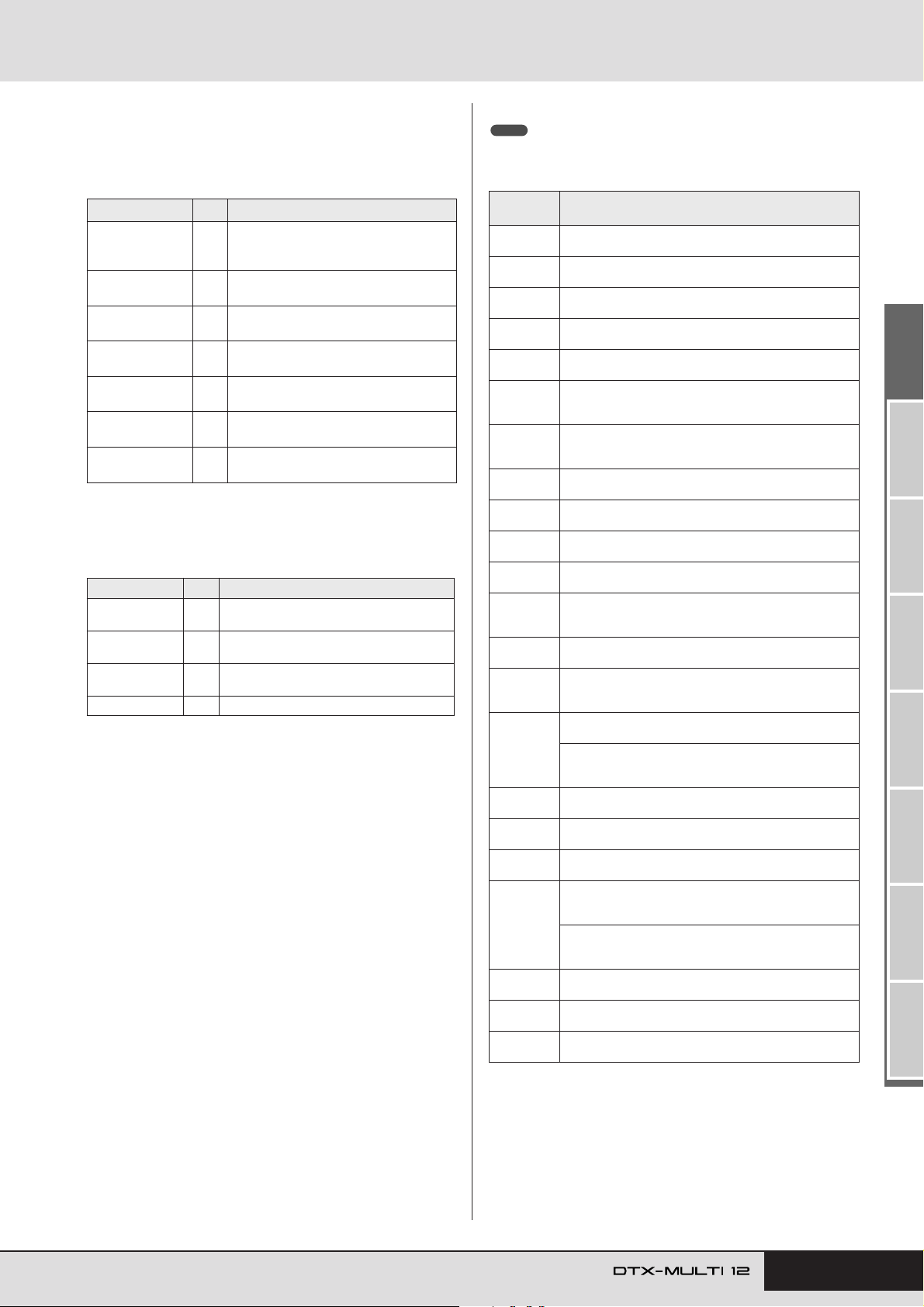
Internal Design
● Delay
Delay effects create a delayed version of the input signal,
and as such, they can be used for many different purposes,
such as creating a sense of spaciousness or thickening a
sound.
Effect Type Va r Description
CrossDelay ✓
TempoCrosDly ✓
TempoDlyMono ✓
TempoDlySt ✓
Delay LR ✓
Delay LCR ✓
Delay LR St ✓
A pair of delays featuring cross-over feedback to produce a sound that swirls
between the left and right channels.
A pair of delays with cross-over feedback
and a tempo-synchronized delay time.
A single mono delay synchronized with the
instrument’s tempo.
A stereo delay synchronized with the
instrument’s tempo.
A delay with separate left and right channels.
A triple delay processing left, right, and
center channels independently.
A stereo delay with fully independent left
and right channels.
● Miscellaneous
This category contains effect types not included in the
other categories.
Effect Type Va r Description
Isolator ✓
Telephone ✓
TalkingMod ✓
PitchChange ✓ Changes the pitch of the input signal.
Controls the volume of individual frequency
bands using powerful filters.
Reproduces the sound of telephone speech
by cutting high and low frequencies.
Incorporates a vowel-type formant into the
input signal.
■ Effect Parameters
Each of the above-mentioned effects includes a range of
parameters allowing you to adjust the way in which it processes the input signal. Using these parameters, the behavior of each effect can be optimized in line with, for
example, the type of sound being processed or the type of
music being played. While the function of each of these
parameters is described in the following table, it is good
practice to also listen to how they actually change the
sound of the respective effect in order to achieve the best
settings.
● Parameters with identical names
NOTE
• Certain effects contain parameters with identical names yet performing different functions. In the following table, the function of each such parameter
is described separately and the corresponding effects are identified.
Parameter
name
AMDepth
AmpType
Attack
Bottom*
Color*
CommonRel
Compres
Cutoff
Delay
DelayC
DelayL
DelayL>R
DelayR
DelayR>L
Density
Depth
Detune
Device
Diffuse
Directn
Div.FreqH
Div.FreqL
*1 The Bottom parameter’s setting is valid only when less than that of
the Top parameter.
*2 The Color parameter’s setting has no effect with certain combina-
tions of Mode and Stage settings.
This parameter is used to set the depth of amplitude
modulation.
This parameter is used to set the type of amplifier to be
simulated.
This parameter is used to set the amount of time that
elapses before compression is fully applied.
This parameter is used to set the lowest point in the fil-
1
ter’s sweep range.
This parameter is used to set the fixed phase modula-
2
tion.
This parameter is used to set the amount of time that
elapses before the compressor stops processing the
input signal (common for all three bands).
This parameter is used to set the input-signal level at
which the compressor starts to process the sound (i.e.,
the threshold).
This parameter is used to set the offset value for the filter’s control frequency.
This parameter is used to set the delay time in terms of
note lengths.
This parameter is used to set the delay time for the center channel.
This parameter is used to set the delay time for the left
channel.
This parameter is used to set the time that elapses
between input of sound via the left channel and output
via the right channel.
This parameter is used to set the delay time for the right
channel.
This parameter is used to set the time that elapses
between input of sound via the right channel and output
via the left channel.
[Reverb effects other than EarlyRef]
This parameter is used to set the reverb density.
[Early Ref]
This parameter is used to set the density of early reflections.
This parameter is used to set the amplitude of the LFO
wave that controls cyclic changes in phase modulation.
This parameter is used to set the degree to which
pitches are detuned.
This parameter is used to select one of a number of
devices that distort the sound in different ways.
[TempoPhaser and EarlyRef]
This parameter is used to adjust the spaciousness of the
sound produced.
[Reverb effects other than EarlyRef]
This parameter is used to set how wide the reverb
sounds.
This parameter is used to set the direction of envelopefollower modulation.
This parameter is used to set the mid-high frequency
when splitting the sound into three bands.
This parameter is used to set the low-mid frequency
when splitting the sound into three bands.
Descriptions
TRIGGER ReferenceKITMIDI VOICEUTILITY WAVEPATTERN
Owner’s Manual 39
Page 40
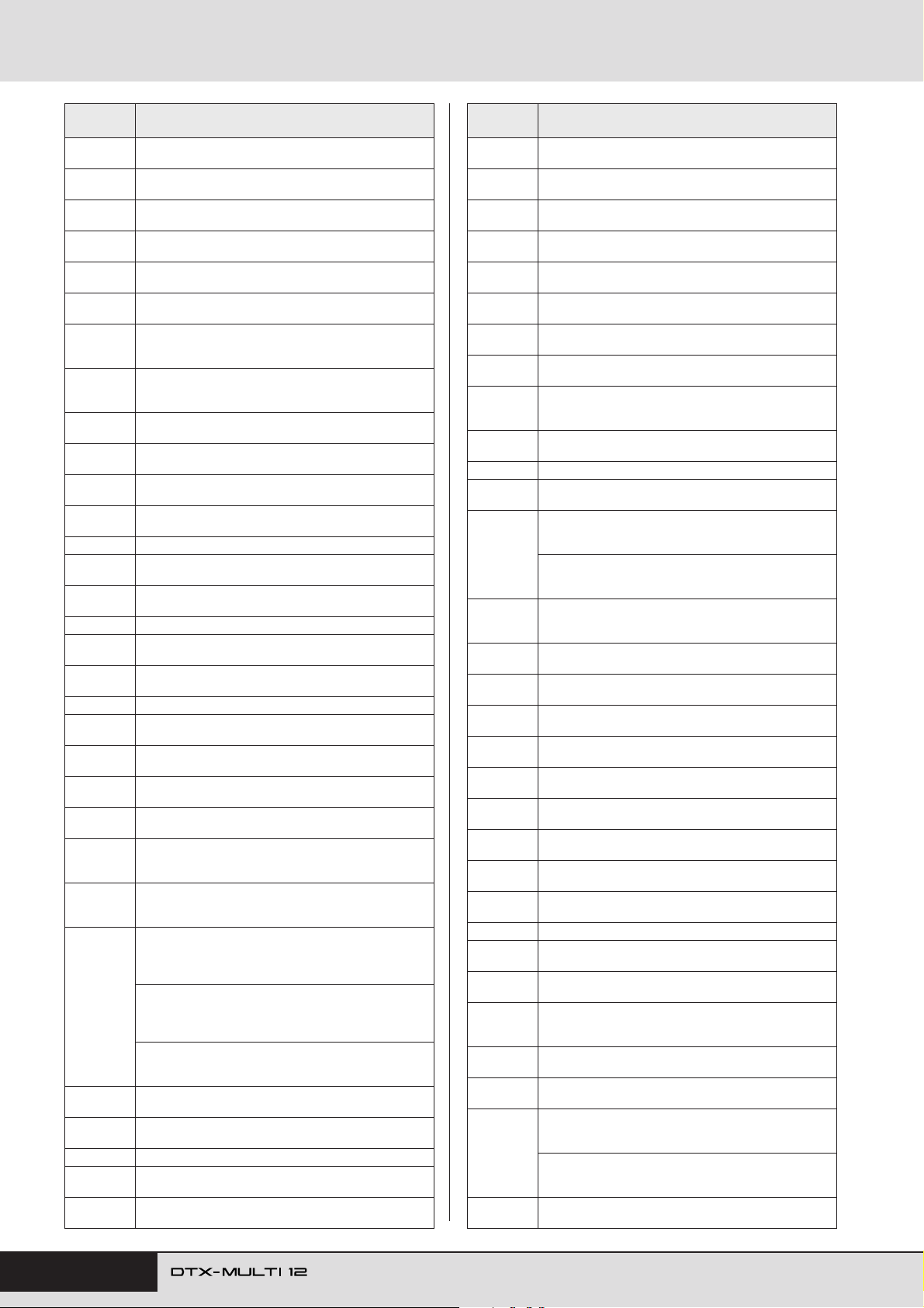
Internal Design
Parameter
name
DlyLvlC
DlyMix
DlyOfst
Drive
DriveHorn
DriveRotor
DstL.Gain
DstM.Gain
Edge
EQ1Freq
EQ1Gain
EQ2Freq
EQ2Gain This parameter is used to set the gain for the EQ2 band.
EQ2Q
EQ3Freq
EQ3Gain This parameter is used to set the gain for the EQ3 band.
EQ3Q
EQ4Freq
EQ4Gain This parameter is used to set the gain for the EQ4 band.
EQ4Q
EQ5Freq
EQ5Gain
ER/Rev
F/RDpth
FBHiDmp
FBLevel
FBLvl1
FBLvl2
FBTime This parameter is used to set the feedback delay time.
FBTime1
FBTime2
This parameter is used to set the delay volume for the
center channel.
This parameter is used to set the mixing level for the
delayed sound.
This parameter is used to set the modulation delay
time’s offset value.
This parameter is used to set the degree to which the
effect is applied.
This parameter is used to set the depth of modulation
produced through rotation of the high-frequency horn.
This parameter is used to set the depth of modulation
produced through rotation of the low-frequency rotor.
This parameter is used to set the degree by which the
low frequencies from the distorted sound are boosted or
cut.
This parameter is used to set the degree by which the
mid frequencies from the distorted sound are boosted or
cut.
This parameter is used to specify a curve that determines how the sound is distorted.
This parameter is used to set the cutoff frequency for the
EQ1 band (i.e., low shelving).
This parameter is used to set the gain for the EQ1 band
(i.e., low shelving).
This parameter is used to set the center frequency for
the EQ2 band.
This parameter is used to set the resonance of the EQ2
band.
This parameter is used to set the center frequency for
the EQ3 band.
This parameter is used to set the resonance of the EQ3
band.
This parameter is used to set the center frequency for
the EQ4 band.
This parameter is used to set the resonance of the EQ4
band.
This parameter is used to set the cutoff frequency for the
EQ5 band (i.e., high shelving).
This parameter is used to set the gain for the EQ5 band
(i.e., high shelving).
This parameter is used to set the relative volumes of
early reflections and reverberation.
This parameter is used to set the front-to-rear pan depth
(and is valid only when PanDirectn is set to “Lturn” or
“Rturn”).
This parameter is used to set how the feedback sound
decays in the high-frequency band (with smaller values
corresponding to faster decay).
[Chorus effects, Delay effects, and TempoFlanger]
This parameter is used to set how much of the delay
sound is fed back into the effect’s input (with negative
values indicating that its phase is to be inverted).
[TempoPhaser]
This parameter is used to set how much of the phaser’s
output is fed back into its input (with negative values indicating that its phase is to be inverted).
[Reverb effects]
This parameter is used to set the initial delay’s feedback
level.
This parameter is used to set the feedback level for the
first delay sound.
This parameter is used to set the feedback level for the
second delay sound.
This parameter is used to set the delay time for feedback
delay 1.
This parameter is used to set the delay time for feedback
delay 2.
Descriptions
Parameter
name
FBTimeL
FBTimeR
Feedback
Fine1
Fine2
H.Freq
H.Gain
Height
HiAtk
HiGain
HiLvl This parameter is used to set the high-frequency level.
HiMute
HiRat
HiTh
HornF
HornS
HPF
InitDly
InitDly1
InitDly2
InitDlyL
InitDlyR
InpMode
InpSelect This parameter is used to select an input.
L.Freq
L.Gain
L/RDiffuse
L/RDpth
Lag
LFODpth
LFODiff
This parameter is used to set the delay time for the left
feedback delay.
This parameter is used to set the delay time for the right
feedback delay.
This parameter is used to set how much of the effect’s
output is fed back into its input.
This parameter is used to adjust the first fine-pitch setting.
This parameter is used to adjust the second fine-pitch
setting.
This parameter is used to set the center frequency of the
high-frequency EQ band.
This parameter is used to set the amount by which the
high-frequency EQ band is boosted or cut.
This parameter is used to set the height of the simulated
room.
This parameter is used to set the amount of time that
elapses before compression is fully applied in the highfrequency band.
This parameter is used to set the output level of the highfrequency band.
This parameter is used to activate and deactivate highfrequency muting.
[MltBndComp]
This parameter is used to set the compression ratio for
the high-frequency band.
[Reverb effects]
This parameter is used to adjust the high-frequency
component.
This parameter is used to set the input-signal level at
which the compressor starts to process the sound in the
high-frequency band.
This parameter is used to set the speed of rotation of the
high-frequency horn at the “fast” setting.
This parameter is used to set the speed of rotation of the
high-frequency horn at the “slow” setting.
This parameter is used to set the high-pass filter’s cutoff
frequency.
This parameter is used to set the amount of time that
elapses before early reflections are produced.
This parameter is used to set the delay time for the first
delay.
This parameter is used to set the delay time for the second delay.
This parameter is used to set the delay time for the leftchannel delay.
This parameter is used to set the delay time for the rightchannel delay.
This parameter is used to switch between mono and stereo input.
This parameter is used to set the center frequency of the
low-frequency EQ band.
This parameter is used to set the amount by which the
low-frequency EQ band is boosted or cut.
This parameter is used to set the difference between left
and right delay times in order to produce a more spacious sound.
This parameter is used to set the depth of the left-right
panning effect.
This parameter is used to set a time lag for delay times
specified in terms of note lengths.
[SPX Flanger, TempoFlanger, SPX Chorus, and Symphonic]
This parameter is used to set the depth of modulation.
[Tempo Phaser]
This parameter is used to set the depth of phase modulation.
This parameter is used to set the left-right phase difference between modulation waveforms.
Descriptions
40 Owner’s Manual
Page 41
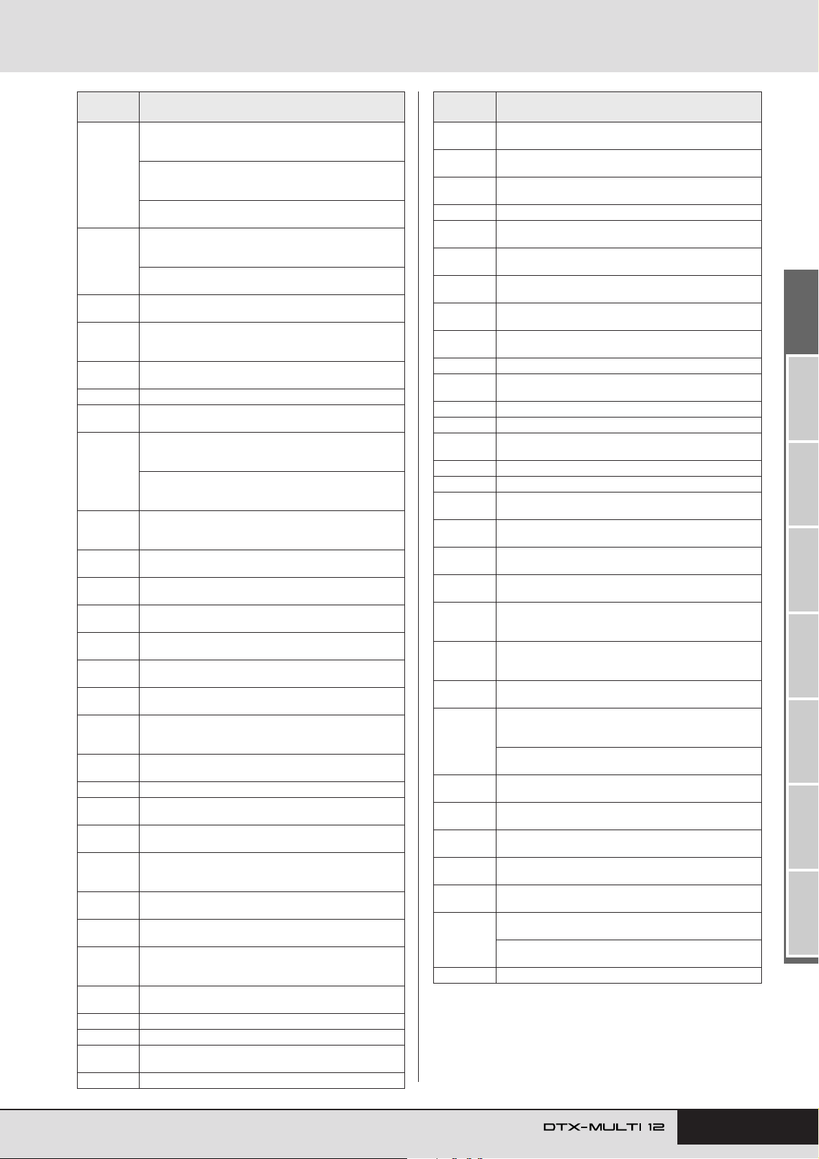
Internal Design
Parameter
name
[TempoFlanger, G Chorus, 2 Modulator, SPX Chorus,
Symphonic, and Tremolo]
This parameter is used to set the modulation frequency.
LFOSpeed
LFOWave
Livenss
LowAtk
LowGain
LowLvl This parameter is used to set the low-frequency level.
LowMute
LowRat
LowTh
LPF
M.Freq
M.Gain
M.Width
Manual
MicAngl
MidAtk
MidGain
MidLvl This parameter is used to set the mid-frequency level.
MidMute
MidRat
MidTh
MixLvl
Mode
MoveSpeed
On/Off
OutLvl This parameter is used to set the output level.
OutLvl1 This parameter is used to set the first-stage output level.
OutLvl2
Output This parameter is used to set the output level.
[TempoPhaser]
This parameter is used to set the modulation speed in
terms of note lengths.
[AutoPan]
This parameter is used to set the auto-pan frequency.
[AutoWah]
This parameter is used to specify whether the filtersweep effect is produced using a sine or square wave.
[AutoPan]
This parameter is used to set the panning curve.
This parameter is used to set the way in which early
reflections decay.
This parameter is used to set the amount of time that
elapses before compression is fully applied in the lowfrequency band.
This parameter is used to set the output level of the lowfrequency band.
This parameter is used to activate and deactivate lowfrequency muting.
[MltBndComp]
This parameter is used to set the compression ratio for
the low-frequency band.
[Reverb effects]
This parameter is used to adjust the low-frequency component.
This parameter is used to set the input-signal level at
which the compressor starts to process the sound in the
low-frequency band.
This parameter is used to set the low-pass filter’s cutoff
frequency.
This parameter is used to set the center frequency of the
mid-frequency EQ band.
This parameter is used to set the amount by which the
mid-frequency EQ band is boosted or cut.
This parameter is used to set the width of the mid-frequency EQ band.
This parameter is used to set the phase-modulation offset value.
This parameter is used to set the left-right inclination of
the microphone used to capture the speaker’s output.
This parameter is used to set the amount of time that
elapses before compression is fully applied in the midfrequency band.
This parameter is used to set the output level of the midfrequency band.
This parameter is used to activate and deactivate midfrequency muting.
This parameter is used to set the compression ratio for
the mid-frequency band.
This parameter is used to set the input-signal level at
which the compressor starts to process the sound in the
mid-frequency band.
This parameter is used to set how much of the effect
sound is mixed back into the dry sound.
This parameter is used to adjust the mode of operation
of the phaser.
This parameter is used to specify the amount of time that
elapses until the sound set using the Vowel parameter is
produced.
This parameter is used to activate and deactivate the
isolator.
This parameter is used to set the second-stage output
level.
Descriptions
Parameter
name
OverDr
Pan1
Pan2
PanDirectn This parameter is used to set the auto-pan type.
PhShiftOfst
Pitch1
Pitch2
PMDepth
Presenc
Ratio This parameter is used to set the compression ratio.
Release
Resonance This parameter is used to set the resonance of the filter.
ResoOfst This parameter is used to set the resonance offset value.
RevDly
RevTime This parameter is used to set the reverb time.
RoomSize This parameter is used to set the size of the room.
Rotor/Horn
RotorF
RotorS
Sens
S-FTmHorn
S-FTmRotor
Speaker
Speed
SpeedCtrl
Spread
Stage
Thresh
*3
To p
Type
Vowel This parameter is used to select a vowel type.
*3 The Top parameter’s setting is valid only when equal to or greater
than that of the Bottom parameter.
This parameter is used to adjust the way in which the
sound distorts.
This parameter is used to set the first stereo-panning
position.
This parameter is used to set the second stereo-panning
position.
This parameter is used to set the phase-modulation offset value.
This parameter is used to set the first pitch in semi-tone
units.
This parameter is used to set the second pitch in semitone units.
This parameter is used to set the depth of pitch modulation.
Often seen on guitar amplifiers and the like, this parameter is used to control the high-frequency band.
This parameter is used to set the amount of time that
elapses until the sound is no longer being compressed.
This parameter is used to set the interval between early
reflections and subsequent reverberation.
This parameter is used to set the relative volumes of the
high-frequency horn and the low-frequency rotor.
This parameter is used to set the speed of rotation of the
low-frequency rotor at the “fast” setting.
This parameter is used to set the speed of rotation of the
low-frequency rotor at the “slow” setting.
This parameter is used to set how sensitive the wah filter
is to changes in the input level.
This parameter is used to set how long it takes for the
high-frequency horn to switch between fast and slow
rotation speeds.
This parameter is used to set how long it takes for the
low-frequency rotor to switch between fast and slow
rotation speeds.
This parameter is used to select the type of speaker to
be simulated.
[PhaserMono and PhaserStereo]
This parameter is used to set the frequency of the LFO
that controls cyclic changes in phase modulation.
[AutoWah]
This parameter is used to set the LFO speed.
This parameter is used to set the rotation speed as “fast”
or “slow”.
This parameter is used to set how wide the effect’s output sounds.
This parameter is used to set the number of phase-filter
steps.
This parameter is used to set the input-signal level at
which the effect starts to process the sound.
This parameter is used to set the highest point in the filter’s sweep range.
[Wah effects]
This parameter is used to set the wah-effect type.
[EarlyRef, GateReverb, and ReverseGate]
This parameter is used to set the reflected-sound type.
Descriptions
TRIGGER ReferenceKITMIDI VOICEUTILITY WAVEPATTERN
Owner’s Manual 41
Page 42
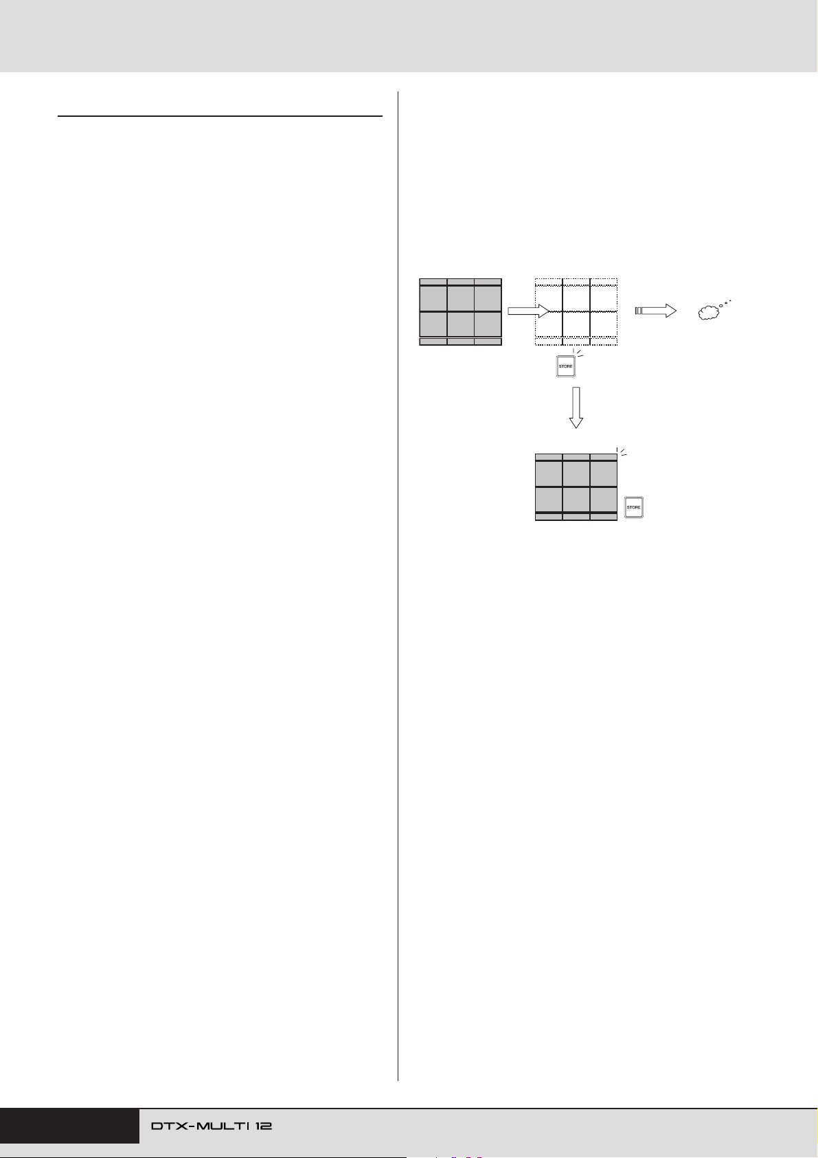
Internal Design
Internal Memory
By storing User kits, User patterns, and waves that you
have created and edited in the DTX-MULTI 12’s internal
memory, you ensure that they will always be available for
use, even after the instrument has been turned off. In addition, User trigger setups and the settings from the UTILITY setting area can also be stored in memory for reuse.
■ Data Retained by the DTX-MULTI 12
The following types of setting data can be stored in the
instrument’s internal memory.
● User kits
Original drum kits that you have created by assigning
voices to pads and external controllers can be stored as
User kits in the instrument’s memory. After doing so, you
can then recall these kits at any time in the same way as
Preset kits. In total, up to 200 User kits can be stored, and
they will be available even after the DTX-MULTI 12 has
been turned off. In addition to settings from the KIT area,
each User kit also retains associated data configured in the
VOICE and MIDI setting areas.
■ Editing & Storing User Kits
Whenever you select a drum kit, the corresponding data is
loaded into a non-permanent area of internal memory
known as the Edit Buffer. If any of the kit’s parameter settings are changed, it is the data within the Edit Buffer – not
the stored version – that is modified. In this way, User kits
can be protected from accidental or unintended modification.
Kit being edited
(User or Preset)
[STORE] button
lights up.
When the kit is stored,
the version in permanent
memory is updated with
all modifications.
Edit buffer (containing
all modifications)
If the DTX-MULTI 12 is
turned off without storing the kit, all modifications will be lost.
● User patterns
User patterns – which may be put to use in exactly the
same way as Preset patterns – can be created by recording
your performances on the DTX-MULTI 12 or by importing
standard MIDI files (Format 0). The corresponding data is
stored as a User pattern within the DTX-MULTI 12 as it is
recorded or imported, and the pattern will then be available
even after the DTX-MULTI 12 has been turned off. Up to
50 of these User patterns can be stored internally.
● Waves
Wave data created by importing either WAV or AIFF type
audio files from a USB memory device (connected via the
USB TO DEVICE port) is automatically stored within the
DTX-MULTI 12 and can then be assigned to pads for playback in the same way as preset voices and patterns. In total,
up to 500 of these waves can be stored, ensuring that they
will be available even after the DTX-MULTI 12 has been
turned off.
● User trigger setups
The DTX-MULTI 12 can also store a number of original
User trigger setups, which you can conveniently prepare by
customizing a Preset trigger setup. In specific terms, the
instrument’s internal memory can hold ten of these setups,
ensuring that they will always be available, even after the
power has been turned off and back on.
[STORE] button
goes out.
The purpose of the Edit Buffer is to hold a temporary version of the kit being edited, and therefore, if a new kit is
selected without storing any modifications, those modifications will be lost (i.e., overwritten with the settings from
the newly selected kit). In addition, modifications to the kit
in the Edit Buffer will also be lost when the DTX-MULTI
12 is turned off if they are not stored in advance. It is good
practice, therefore, to store the content of the Edit Buffer as
a User kit whenever you are happy with it.
■ Saving & Loading Data Files
All of the above-mentioned items of data that can be stored
in the instrument’s internal memory can also be saved as
files on a USB storage device. Whenever needed, furthermore, these memory files can be loaded back into the
instrument from the storage device. For more details, refer
to the description of the UTILITY setting area’s FILE section (UTIL7).
● UTILITY area settings
The parameter settings that you have configured within the
UTILITY setting area can also be stored in the DTXMULTI 12’s internal memory. In this way, they can be
instantly recalled whenever the instrument is turned on.
42 Owner’s Manual
Page 43
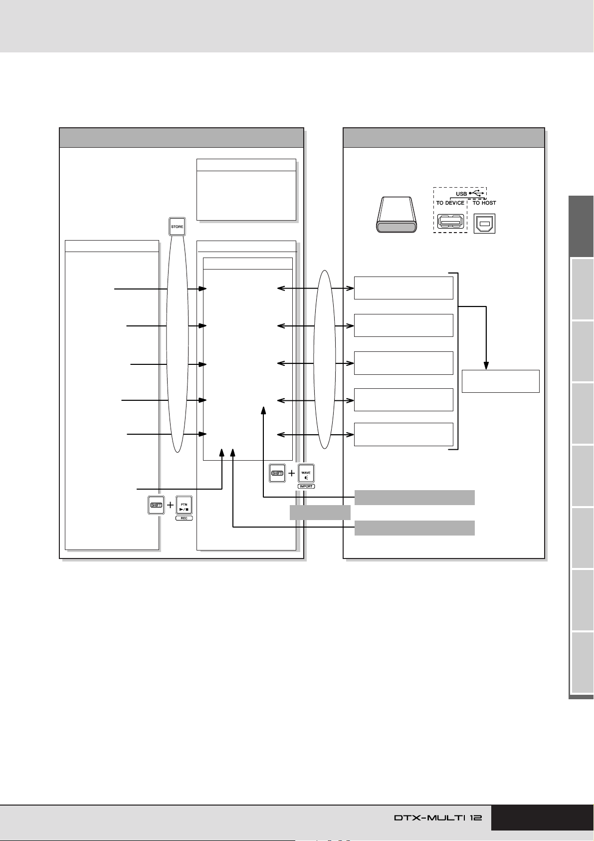
Internal Design
■ Makeup of Internal Memory
The following diagram shows the correlation between the various functions that can be used to create data on the DTXMULTI 12, the data in the instrument’s internal memory, and the data on a USB memory device.
Data-creating functions
• Kit editing
•Voice setting
• MIDI setting
•Trigger setting
• Utility setting
•Wave editing
Internal memory
Store
Preset data (ROM)
• Kits
•Voices
•Patterns
•Trigger setups
User memory
Flash ROM
• User kits
• User trigger
setups
• Utility setting
•Waves
UTIL7
FILE
Save / Load
External USB memory device
File extension: .MTK
(file type = “AllKit”)
All combined
File extension: .MMT
(file type = “AllTrigger”)
File extension: .MTU
(file type = “Utility”)
File extension: .MTA
(file type = “All”)
File extension: .MTW
(file type = “AllWave”)
•Pattern editing
•Pattern recording
• User
patterns
Record
Import SMF
(PTN4-7)
File extension: .MTP
(file type = “AllPattern”)
Audio data (.WAV or .AIFF)
Import
Standard MIDI file (.MID)
TRIGGER ReferenceKITMIDI VOICEUTILITY WAVEPATTERN
Owner’s Manual 43
Page 44
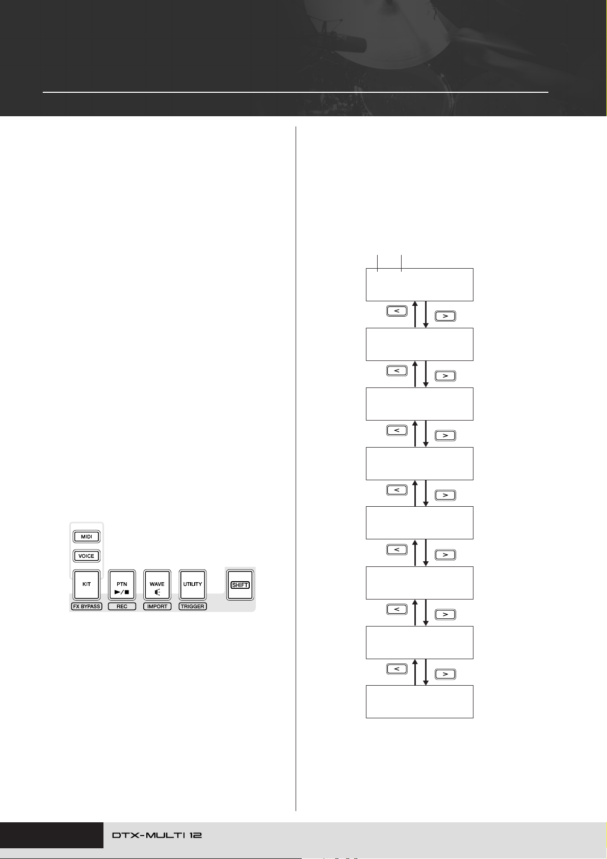
Basic Operations
The following section describes how to perform basic tasks
such as the changing of parameter settings, execution of
jobs, and storing of data.
■ Parameter Setting Areas
Within your DTX-MULTI 12, parameters associated with
specific functions are conveniently grouped together into
seven different parameter setting areas. These areas may be
accessed using the buttons indicated below.
• KIT setting area: [KIT] button
This area is used to select and edit drum kits.
•VOICE setting area: [VOICE] button
A part of the KIT setting area, this area is used to select
and edit voices.
•MIDI setting area: [MIDI] button
A part of the KIT setting area, this area is used to set
MIDI-related parameters on an individual-kit basis.
•PATTERN setting area: [PTN] button
This area is used to select and edit patterns.
•WAVE setting area: [WAVE] button
This area is used to import and edit waves.
• UTILITY setting area: [UTILITY] button
This area is used to set parameters affecting the overall
system and to manage files.
• TRIGGER setting area: [SHIFT] + [UTILITY] buttons
This area is used to edit trigger setup data.
■ Navigating between Sections
Each setting area is subdivided into a number of different
sections. The current section is indicated at the left of the
upper row of text using the name (or abbreviation) of the
selected setting area together with the section number. Use
the [B]/[C] buttons to navigate between these sections.
Example: UTILITY setting area
Name of selected
area (UTILITY) Section number
UTIL1
≥≥≥≥GENERAL
UTIL2
≥≥≥≥≥CLICK
UTIL3
≥≥≥MASTER≥EQ
UTIL4
≥≥≥≥≥≥PAD
The button corresponding to each setting area will light up
in green when that area is selected. In the case of the
VOICE and MIDI setting areas, the [KIT] button will also
light up.
UTIL5
≥≥≥≥≥HI-HAT
UTIL6
≥≥≥≥≥≥MIDI
UTIL7
≥≥≥≥≥≥FILE
UTIL8
≥≥FACTORY≥SET
44 Owner’s Manual
Page 45
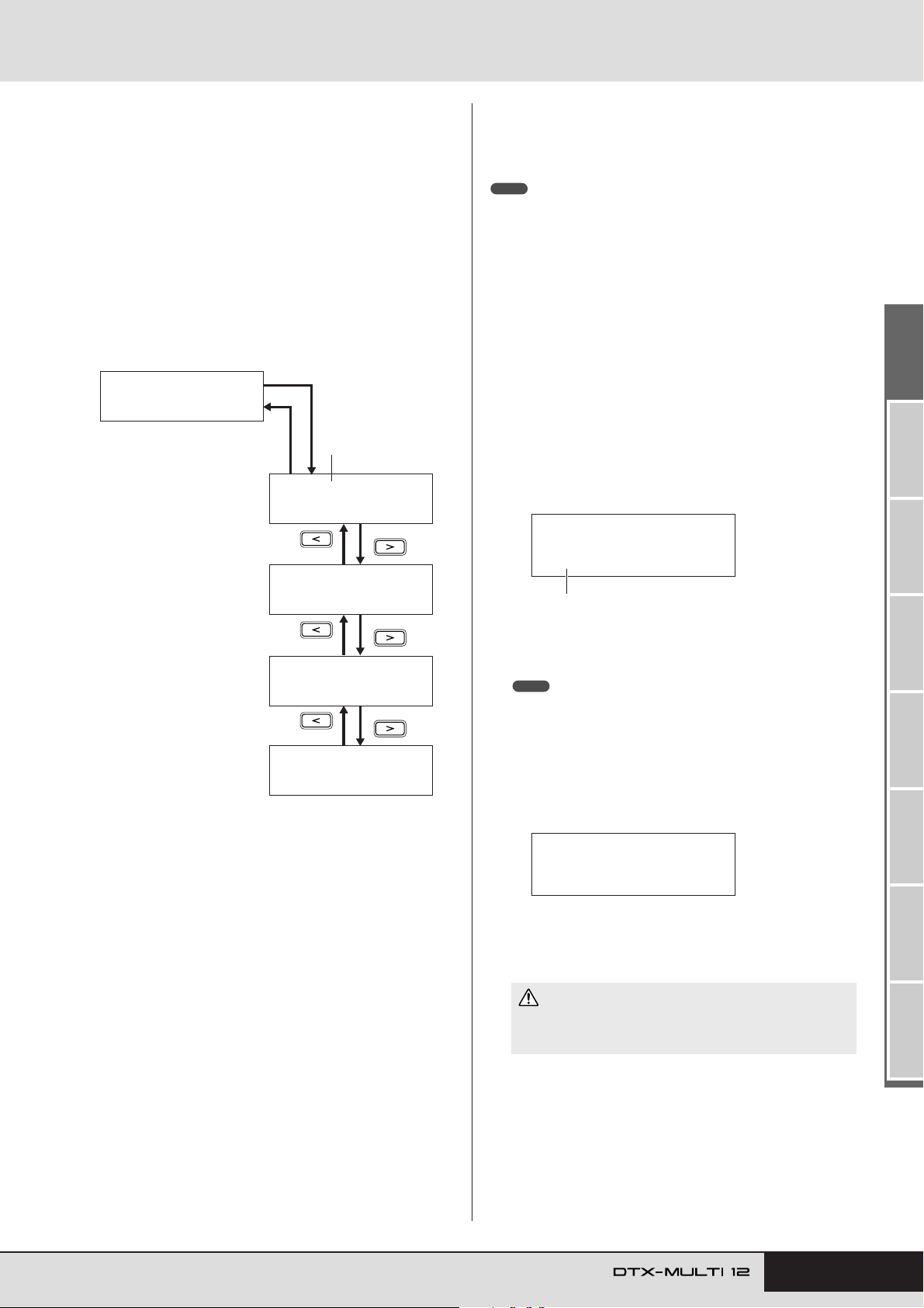
Basic Operations
KIT≥Store≥to
U001:User≥Kit
Destination for stored data.
≥≥≥KIT≥Store
≥Are≥you≥sure?
■ Navigating between Pages
Each section contains a number of parameter setting pages
that are used to make actual settings. With a section page
displayed, press the lit [ENTER] button to access its
parameter setting pages. (In certain cases, it may not be
possible to access parameter-setting pages from a section
page, and the [ENTER] button will not light up.) Each
parameter-setting page is identified at the left of the upper
row of text using the name (or abbreviation) of the setting
area, the section number, and the page number (with
hyphens between the numbers). You can use the [B]/[C]
buttons to navigate between parameter setting pages.
Example: VOICE setting area’s TONE section (VCE3)
[ENTER]
VCE3
≥≥≥≥≥≥TONE
Page number
[EXIT]
VCE3-1≥-º¡-≥≥≥≥ç
≥≥≥Attack=+≥0
■ Changing Parameter Settings
By pressing the [-/DEC] or [+/INC] button, you can
increase or decrease the setting of the currently selected
parameter.
NOTE
•A setting can be decreased in units of 10 by holding down the [SHIFT] button and pressing the [-/DEC] button or by holding down the [-/DEC] button
and pressing the [+/INC] button.
• Similarly, it can be increased in units of 10 by holding down the [SHIFT] button and pressing the [+/INC] button or by holding down the [+/INC] button
and pressing the [-/DEC] button.
■ Storing Parameter Settings
Whenever parameter settings have been changed on section
and/or parameter-setting pages, the [STORE] button will
light up to remind you to store your settings. The correct
way to store parameter settings is as follows.
When you have finished setting parameters in a specific
1
setting area, press the [STORE] button to open the Store
Kit page.
VCE3-2≥-º¡-≥≥≥≥ç
≥≥≥Decay=+≥0
VCE3-3≥-º¡-≥≥≥≥ç
≥≥Release=+≥0
VCE3-4≥-º¡-≥≥≥≥ç
≥Fc=+≥0≥≥Q=+≥0
In certain cases, a number of additional pages may be
accessed from a parameter setting page using the [ENTER]
button, which will light up whenever this is possible. By
pressing the [EXIT] button, you can move back towards the
top of the current setting area.
■ Moving the Cursor
Whenever a page contains a number of different parameters, you can move the flashing cursor left and right using
the [B]/[C] buttons or between the upper and lower rows
of text using the [D] button. In this way, you can select the
parameter setting to be changed (as described below). If
there are no additional parameters to the left or right on the
current page when you press the [B]/[C] button, the cur-
sor will jump to the next parameter-setting page to the left
or right, respectively. In addition, the [B]/[C] and [D]
buttons will light up whenever they can be pressed to move
to a different parameter on the current page or an adjacent
page.
Using the [-/DEC] and [+/INC] buttons, indicate where
2
you want your data to be stored.
NOTE
• The above step is not required when storing settings in the UTILITY
setting area.
Press the [ENTER] button. You will be asked to confirm
3
that you wish to proceed. If necessary, you can press the
[EXIT] button to return to the previous page without storing any data.
Press the [ENTER] button to store your data in the DTX-
4
MULTI 12’s internal memory.
CAUTION
• If you turn off the instrument without storing modified settings,
these modifications will lost (i.e., the settings will revert to their
previous state when the instrument is next turned on).
TRIGGER ReferenceKITMIDI VOICEUTILITY WAVEPATTERN
Owner’s Manual 45
Page 46
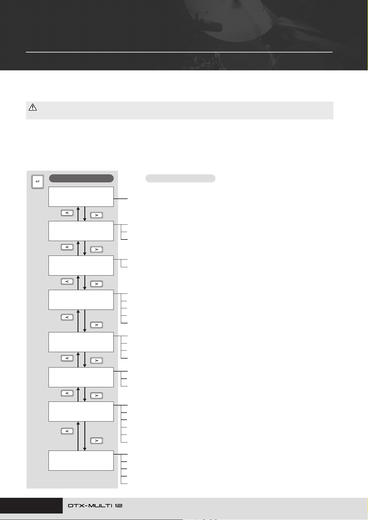
KIT Setting Area (KIT)
This section describes the KIT setting area, which can be accessed using the [KIT] button. Your DTX-MULTI 12 is preloaded with a rich selection of Preset kits (P001 to P050) for immediate use, and you can also create and save up to
200 of your own drum kits as User kits (U001 to U200). Use the KIT setting area to select and edit these drum kits.
CAUTION
• Be sure to store any settings that you have edited before turning off the instrument or selecting a new kit. (See page 45.)
Makeup of KIT Setting Area
The KIT setting area is subdivided into eight different sections (KIT1 to KIT8). Use the [B]/[C] buttons to navigate between these sec-
tions. If a section contains parameter-setting pages, the [ENTER] button will light up. Press the [ENTER] button to access these pages. In
certain cases, a number of additional pages may be accessed from a parameter setting page, also using the lit [ENTER] button. Furthermore,
you can press the [EXIT] button to move back towards the top of the setting area.
Sections
KIT1
P001:PercsMaster
KIT2≥≥≥≥≥≥≥≥≥≥≥≥
≥≥≥≥≥COMMON≥≥≥≥≥
KIT3
≥≥EFFECT≥SEND
KIT4
≥≥≥VARIATION
KIT5
≥≥≥≥≥CHORUS
Parameter-setting pages
Select Kit ......................................................................................................... Page 47
KIT2-1 Kit Volume page .................................................................................. Page 47
KIT2-2 Kit Selection Tempo page.................................................................... Page 47
KIT2-3 Kit Name page..................................................................................... Page 47
KIT3-1 Chorus Send page ..............................................................................Page 48
KIT3-2 Reverb Send page...............................................................................Page 48
KIT4-1 Variation Type page .............................................................................Page 48
KIT4-2 Variation Return page.......................................................................... Page 49
KIT4-3 Variation Pan page ..............................................................................Page 49
KIT4-4 Variation to Reverb page ..................................................................... Page 49
KIT4-5 Variation to Chorus page ..................................................................... Page 49
KIT5-1 Chorus Type page ...............................................................................Page 49
KIT5-2 Chorus Return page ............................................................................ Page 49
KIT5-3 Chorus Pan page ................................................................................Page 50
KIT5-4 Chorus to Reverb page .......................................................................Page 50
46 Owner’s Manual
KIT6
≥≥≥≥≥REVERB
KIT7
≥≥≥≥≥OTHER
KIT8≥≥≥≥≥≥≥≥≥≥≥≥
≥≥≥≥≥≥JOB≥
KIT6-1 Reverb Type page................................................................................Page 50
KIT6-2 Reverb Return page ............................................................................ Page 50
KIT6-3 Reverb Pan page................................................................................. Page 50
KIT7-1 Layer Switch page............................................................................... Page 51
KIT7-2 Mute Switch page................................................................................ Page 51
KIT7-3 Hi-hat Function page ........................................................................... Page 52
KIT7-4 Hi-hat MIDI Channel page................................................................... Page 52
KIT7-5 Hi-hat MIDI Type page......................................................................... Page 52
KIT7-6 Trigger Setup Link page ...................................................................... Page 52
KIT8-1 Copy Pad page.................................................................................... Page 53
KIT8-2 Exchange Pads page .......................................................................... Page 53
KIT8-3 Exchange Kits page ............................................................................Page 54
KIT8-4 Initialize Pad page ............................................................................... Page 54
KIT8-5 Initialize Kit page ................................................................................. Page 54
Page 47
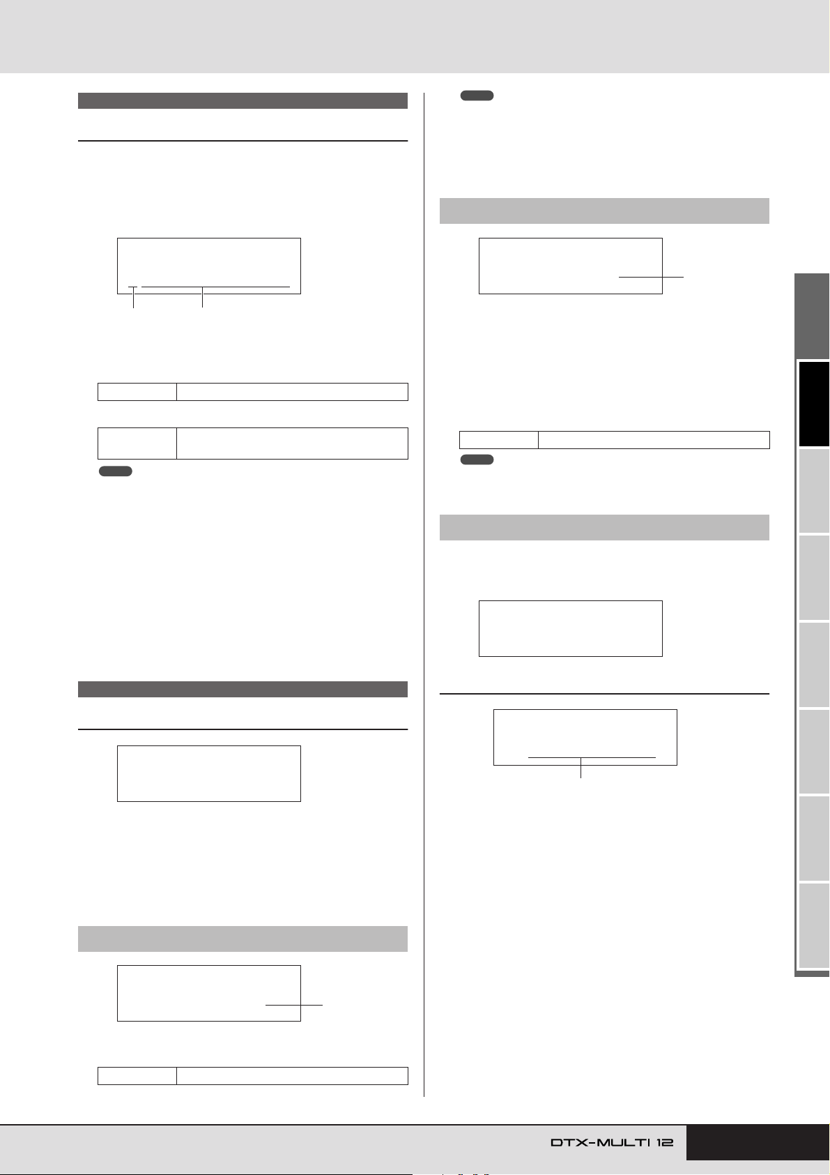
KIT Setting Area (KIT)
KIT2-2≥≥<COMMON>
≥≥≥Tempo=off
1
KIT2-3≥≥<COMMON>
≥≥≥≥≥≥Name
KIT2-3-1
≥≥[User≥Kit≥≥≥]
Kit name
!"#$%&'()*+,-./0123456789:;<=>?@
ABCDEFGHIJKLMNOPQRSTUVWXYZ[\]^_`
abcdefghijklmnopqrstuvwxyz{|}ßå
KIT1
Select Kit
On the Select Kit page (KIT1) you can select the Preset kit or
User kit you want to play. To access this page, press the [KIT]
button, and if necessary, the [B]/[C] buttons. Before you can
edit pads or voices in the VOICE or MIDI setting areas, the drum
kit in question must be selected on this page.
KIT1
P001:PercsMaster
1
A Kit category
Use this parameter to specify either the Preset (P) or User (U)
drum-kit category.
Settings P or U
B Kit number: Kit name
Settings
NOTE
• If you select a new drum kit while a pattern assigned to one if its pads
is being played, the pattern will stop automatically.
• If you select a new drum kit while a preset voice or wave assigned to
one if its pads is being played, the corresponding sound will be automatically silenced.
• If identical voices are assigned to the same Channel-10 MIDI note
numbers in both the newly selected kit and the previous kit, it is normal
for voices for the corresponding pads to continue to play when the new
drum kit is selected.
• If any of the currently selected drum kit’s pads are set to “Hand” on the
Pad Type page (TRG2-1), the Hand icon ( ) will be displayed onscreen (see page 101).
2
With “P” (Preset kit) selected: 001 to 050
With “U” (User kit) selected: 001 to 200
ˇÁ
NOTE
• If you change the volume setting for MIDI channel 10 on the MIDI
area’s Volume page (MIDI3-2), the Volume parameter on this page
(KIT2-1) will be automatically set to the same value. The reverse does
not apply, however – in other words, the volume setting on the MIDI
area’s Volume page (MIDI3-2) is not affected by changes made on this
page (KIT2-1).
KIT2-2 Kit Selection Tempo page
1 Tempo
Use this parameter to specify the tempo to be set automatically upon selection of the current drum kit. If patterns are
assigned to any of the kit’s pads, they will be played at this
tempo. An “off” setting means that the tempo will not change
automatically when the current kit is selected – in other
words, the tempo of the previously selected kit will be maintained.
Settings off, or 30 to 300
NOTE
• If waves are assigned to any of the kit’s pads, the tempo (or speed) at
which they are played will not be affected by the kit’s tempo setting.
KIT2-3 Kit Name page
From the Kit Name page, you can assign a name to the currently
selected drum kit. With this page displayed, press the [ENTER]
button to open the Kit Name Setting page.
KIT2 COMMON
Kit Volume, Tempo & Name
KIT2
≥≥≥≥≥COMMON
In the COMMON section, you can set the volume, tempo, and
name of the currently selected drum kit. With the COMMON
page (KIT2) displayed, press the [ENTER] button to access its
three parameter-setting pages (KIT2-1 to KIT2-3). You can use
the [B]/[C] buttons to navigate between these pages.
KIT2-1 Kit Volume page
KIT2-1≥≥<COMMON>
≥≥≥Volume=118
1 Volume
Use this parameter to set the volume of the entire kit.
Settings 0 to 127
1
KIT2-3-1 Kit Name Setting page
On the Kit Name Setting page, a name of up to 11 characters in
length can be assigned to the currently selected drum kit. Use the
[B]/[C] buttons to move the flashing cursor to the character
you want to change, and then select a character using the [-/DEC]
and [+/INC] buttons. The following characters can be used in
drum-kit names.
[space]
TRIGGER ReferenceKITMIDI VOICEUTILITY WAVEPATTERN
Owner’s Manual 47
Page 48
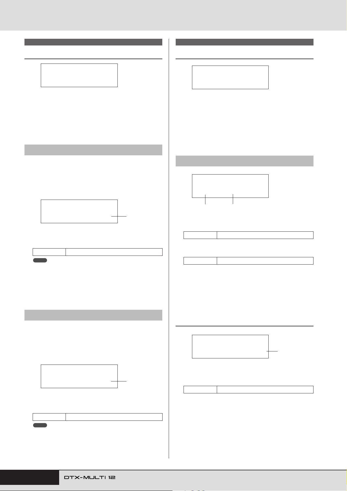
KIT Setting Area (KIT)
KIT3 EFFECT SEND
Effect Send Levels
KIT3
≥≥EFFECT≥SEND
In the EFFECT SEND section, you can adjust the degree to which
chorus and reverb effects are applied to the entire drum kit. With
the EFFECT SEND page (KIT3) displayed, press the [ENTER]
button to access its two parameter-setting pages (KIT3-1 and
KIT3-2). You can use the [B]/[C] buttons to switch between
these pages.
KIT3-1 Chorus Send page
Using the Chorus Send page, you can adjust the degree to which
the chorus effect is applied to all drum voices in the currently
selected kit. If any of the kit’s individual voices also have a chorus-send level set on the VOICE area’s Chorus Send page (VCE4-
2), chorus will be assigned to them in line with the sum of both
send levels.
KIT3-1≥≥<FXSEND>
≥ChorusSend=≥≥0
1 Chorus send level (ChorusSend)
Use this parameter to set the chorus-send level for the currently selected drum kit.
Settings 0 to 127
NOTE
• If you change the chorus-send level for MIDI channel 10 on the MIDI
area’s Chorus Send page (MIDI3-6), the ChorusSend parameter on
this page (KIT3-1) will be automatically set to the same value. The
reverse does not apply, however – in other words, the chorus send setting on the MIDI area’s Chorus Send page (MIDI3-6) is not affected by
changes made on this page (KIT3-1).
KIT3-2 Reverb Send page
Using the Reverb Send page, you can adjust the degree to which
the reverb effect is applied to all drum voices in the currently
selected kit. If any of the kit’s individual voices also have a
reverb-send level set on the VOICE area’s Reverb Send page
(VCE4-3), reverb will be assigned to them in line with the sum of
both send levels.
1
KIT4 VARIATION
Variation Effect Setup
KIT4
≥≥≥VARIATION
In the VARIATION section, you can select a variation effect,
adjust the degree to which it is applied, and configure it in a number of other ways. Variation effects are applied to all voices (on all
MIDI channels). With the VARIATION page (KIT4) displayed,
press the [ENTER] button to access its five parameter-setting
pages (KIT4-1 to KIT4-5). You can use the [B]/[C] buttons to
navigate between these pages.
KIT4-1 Variation Type page
KIT4-1≥≥VarType=
C&E/Compressor
1
1 Variation category
Use this parameter to select a variation-effect category.
Settings Refer to the separate Data List booklet.
B Variation type
Use this parameter to select a variation-effect type.
Settings Refer to the separate Data List booklet.
With an effect category and type selected, you can press the
[ENTER] button on the Variation Type page (KIT4-1) to access a
range of setting pages allowing each of the selected effect’s
parameters to be set. (The number of parameter-setting pages
depends on the effect selected.) Use the [B]/[C] buttons to nav-
igate between these pages.
KIT4-1-1 Parameter setting page (example)
KIT4-1-1≥≥≥<VAR>
LFOSpeed=0.000Hz
2
1
KIT3-2≥≥<FXSEND>
≥ReverbSend=≥35
1 Reverb send level (ReverbSend)
Use this parameter to set the reverb-send level for the currently selected drum kit.
Settings 0 to 127
NOTE
• If you change the reverb-send level for MIDI channel 10 on the MIDI
area’s Reverb Send page (MIDI3-7), the ReverbSend parameter on
this page (KIT3-1) will be automatically set to the same value. The
reverse does not apply, however – in other words, the reverb send setting on the MIDI area’s Reverb Send page (MIDI3-7) is not affected by
changes made on this page (KIT3-2).
48 Owner’s Manual
1
1 Effect parameter
Each parameter setting page contains a different parameter for
the selected variation effect.
Settings Refer to the separate Data List booklet.
Page 49
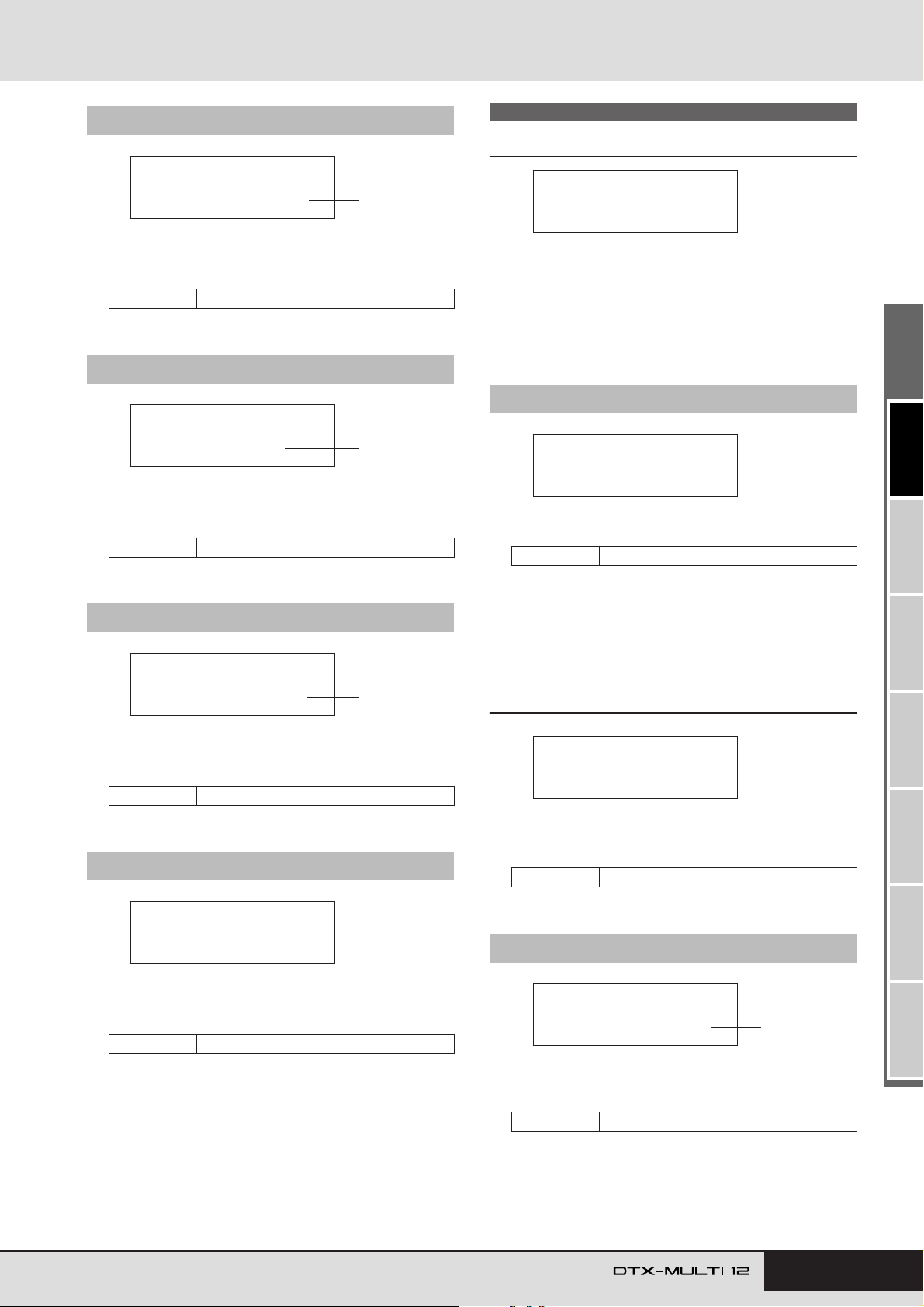
KIT Setting Area (KIT)
KIT5
≥≥≥≥≥CHORUS
KIT5-1≥≥ChoType=
G≥Chorus
1
KIT5-1-1≥≥≥<CHO>
LFOSpeed=0.000Hz
1
KIT5-2≥≥≥≥≥<CHO>
≥ChoReturn=≥64
1
KIT4-2 Variation Return page
KIT4-2≥≥≥≥≥<VAR>
≥VarReturn=≥64
1 Variation return (VarReturn)
Use this parameter to set the level of the return signal from the
variation effect.
Settings 0 to 127
KIT4-3 Variation Pan page
1
KIT4-3≥≥≥≥≥<VAR>
≥≥≥VarPan=≥C
1 Variation pan (VarPan)
Use this parameter to set the stereo panning of the variation
effect’s return signal.
Settings L63 to C to R63
1
KIT5 CHORUS
Chorus Effect Setup
In the CHORUS section, you can select a chorus effect and configure it in a range of different ways. Chorus effects are applied to
all voices (on all MIDI channels). With the CHORUS page
(KIT5) displayed, press the [ENTER] button to access its four
parameter-setting pages (KIT5-1 to KIT5-4). You can use the
[B]/[C] buttons to navigate between these pages.
KIT5-1 Chorus Type page
1 Chorus type
Use this parameter to select a chorus-effect type.
Settings Refer to the separate Data List booklet.
KIT4-4 Variation to Reverb page
KIT4-4≥≥≥≥≥<VAR>
≥≥VarToRev=≥≥0
1 Variation to reverb (VarToRev)
Use this parameter to set the degree to which the output from
the variation effect is sent to the reverb effect.
Settings 0 to 127
KIT4-5 Variation to Chorus page
1
KIT4-5≥≥≥≥≥<VAR>
≥≥VarToCho=≥≥0
1 Variation to chorus (VarToCho)
Use this parameter to set the degree to which the output from
the variation effect is sent to the chorus effect.
Settings 0 to 127
1
With a chorus type selected, you can press the [ENTER] button
on the Chorus Type page (KIT5-1) to access a range of setting
pages allowing each of its parameters to be set. (The number of
parameter-setting pages depends on the type selected.) Use the
[B]/[C] buttons to navigate between these pages.
KIT5-1-1 Parameter setting page (example)
1 Effect parameter
Each parameter setting page contains a different parameter for
the selected chorus type.
Settings Refer to the separate Data List booklet.
KIT5-2 Chorus Return page
1 Chorus return (ChoReturn)
Use this parameter to set the level of the return signal from the
chorus effect.
Settings 0 to 127
TRIGGER ReferenceKITMIDI VOICEUTILITY WAVEPATTERN
Owner’s Manual 49
Page 50
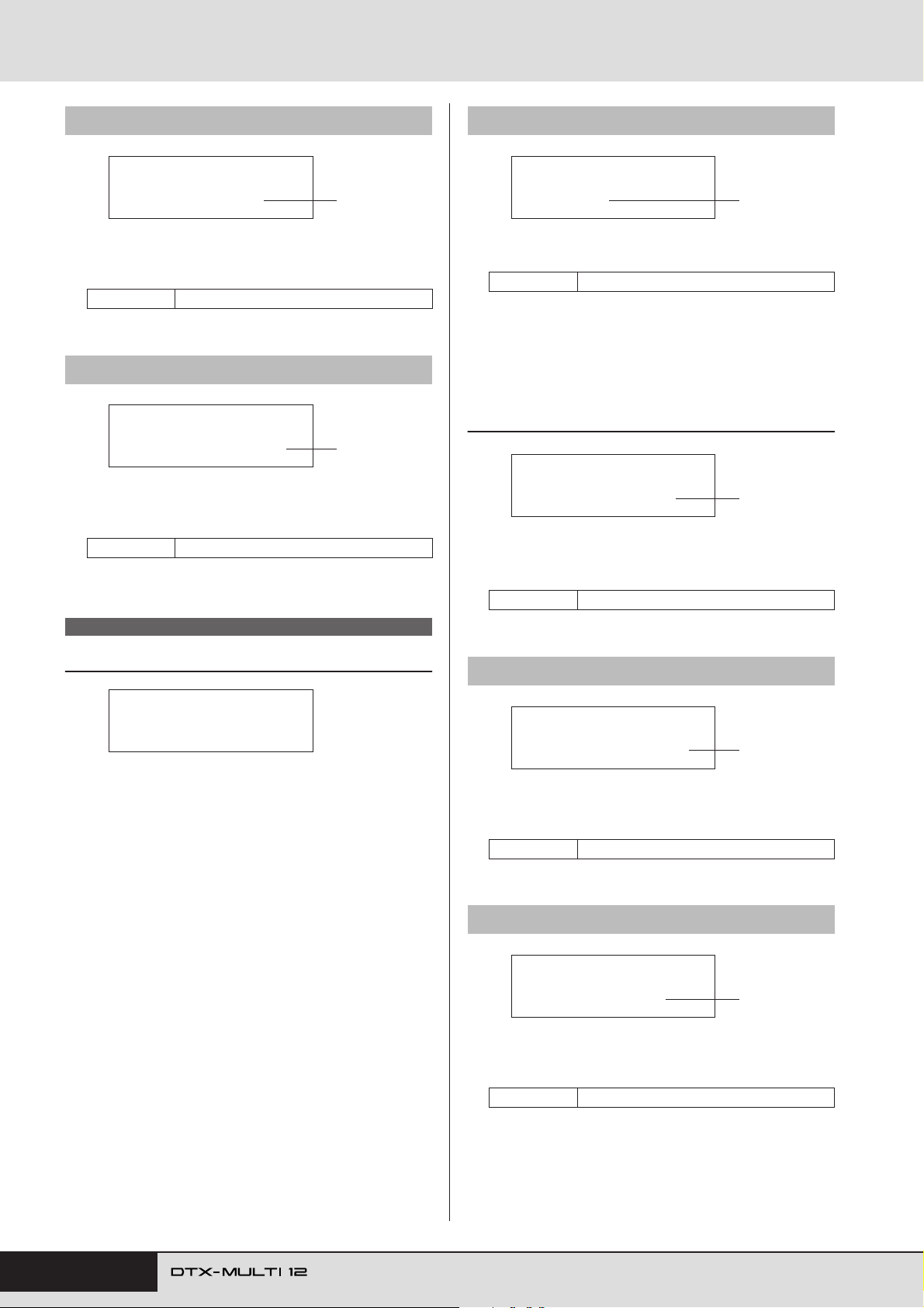
KIT Setting Area (KIT)
KIT5-3 Chorus Pan page
KIT5-3≥≥≥≥≥<CHO>
≥≥≥ChoPan=≥C
1 Chorus pan (ChoPan)
Use this parameter to set the stereo panning of the chorus
effect’s return signal.
Settings L63 to C to R63
KIT5-4 Chorus to Reverb page
1
KIT5-4≥≥≥≥≥<CHO>
≥≥ChoToRev=≥≥0
1 Chorus to reverb (ChoToRev)
Use this parameter to set the degree to which the output from
the chorus effect is sent to the reverb effect.
Settings 0 to 127
1
KIT6-1 Reverb Type page
KIT6-1≥≥RevType=
R3≥Hall
1 Reverb type
Use this parameter to select a reverb-effect type.
Settings Refer to the separate Data List booklet.
With a reverb type selected, you can press the [ENTER] button on
the Reverb Type page (KIT6-1) to access a range of setting pages
allowing each of its parameters to be set. (The number of parame-
ter-setting pages depends on the type selected.) Use the [B]/[C]
buttons to navigate between these pages.
KIT6-1-1 Parameter setting page (example)
1
KIT6-1-1≥≥≥<REV>
RevTime=≥0.0s
1 Effect parameter
Each parameter setting page contains a different parameter for
the selected reverb type.
Settings Refer to the separate Data List booklet.
1
KIT6 REVERB
Reverb Effect Setup
KIT6
≥≥≥≥≥REVERB
In the REVERB section, you can select a reverb effect and configure it in a range of different ways. Reverb effects are applied to all
voices (on all MIDI channels). With the REVERB page (KIT6)
displayed, press the [ENTER] button to access its three parame-
ter-setting pages (KIT6-1 to KIT6-3). You can use the [B]/[C]
buttons to navigate between these pages.
KIT6-2 Reverb Return page
KIT6-2≥≥≥≥≥<REV>
≥RevReturn=≥64
1 Reverb return (RevReturn)
Use this parameter to set the level of the return signal from the
reverb effect.
Settings 0 to 127
KIT6-3 Reverb Pan page
1
KIT6-3≥≥≥≥≥<REV>
≥≥≥RevPan=≥C
1 Reverb pan (RevPan)
Use this parameter to set the stereo panning of the reverb
effect’s return signal.
Settings L63 to C to R63
1
50 Owner’s Manual
Page 51
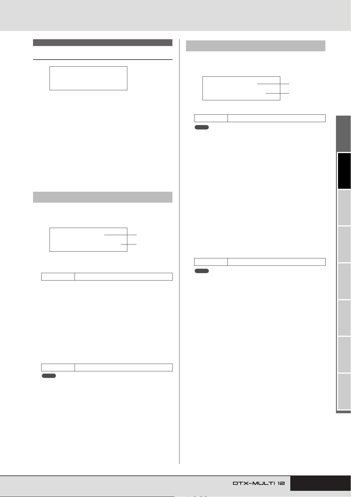
KIT Setting Area (KIT)
KIT7-2≥-º¡≥≥≥MuteSw=off
2
1
KIT7 OTHER
Other Drum Kit Settings
KIT7
≥≥≥≥≥OTHER
In the OTHER section, you can set parameters related to muting*
and hi-hats, and you can also specify the trigger setup to be used
when the current drum kit is selected. With the OTHER page
(KIT7) displayed, press the [ENTER] button to access its six
parameter-setting pages (KIT7-1 to KIT7-6). You can use the
[B]/[C] buttons to navigate between these pages.
*: Muting
The action of pressing a hand down on a pad in order to change the sound
it produces or to silence it is referred to as “muting”. This technique can
be used to delicately change the sound of a performance, and with the
DTX-MULTI 12, you can setup muting in advance in order to change or
silence sounds when you press a hand down on a pad.
KIT7-1 Layer Switch page
Using the Layer Switch function, you can apply the muting technique during performances to switch between the four layers that
can be assigned to built-in and external pads.
KIT7-1≥-º¡LayerSwitch=off
1 Pad number
Use this parameter to select the pad to be set.
Settings 01 to 12, 13, 13R1, 13R2, 14 to 17
B Layer switch
Use this parameter to specify whether or not triggered layers
from the pad indicated by 1 are to be switched in response to
muting or operation of a hi-hat controller. For more details
regarding layers, see page 32.
•off ............. Layers will not be switched.
• mute ......... Layers A and B are played when muting is off.
Layers C and D are played when muting is on.
•hh............. Layers A and B are played when the hi-hat is
open.
Layers C and D are played when the hi-hat is
closed.
Settings off, mute, or hh
NOTE
• The “mute” setting is available only for the twelve built-in pads on your
DTX-MULTI 12.
1
2
KIT7-2 Mute Switch page
On the Mute Switch page, you can select a group of pads to be
treated as one in terms of muting in order to silence or change
their sounds during performances.
1 Pad number
Settings 01 to 12
NOTE
• This parameter can be set only for the twelve built-in pads on your
DTX-MULTI 12.
B Mute switch (MuteSw)
Set this parameter to “on” if muting for the pad indicated by
1 is to operate in conjunction with muting for other pads
with the same setting. When pad sensitivity is set for playing
with sticks, we recommend that you set MuteSw to “on” for at
least two pads so that you can use the muting technique without the fear of accidentally striking your hand. As you make
your selections, the numbers in the Pad Indicator will light up
to show which pads have been grouped together for muting.
Example: If MuteSw has been set to “on” for Pads 4, 5, and 6:
• When you strike Pad 4, 5, or 6 while pressing down on
either of the other two pads by hand, the struck pad will
produce a shorter sound.
• When you press down on Pad 4, 5, or 6 by hand while one
or more of these pads are producing a sound as a result of
being struck, the struck pad(s) will be silenced.
Settings off or on
NOTE
• Be sure to press firmly on a pad when you want to activate the muting
function.
• If you are using the muting technique with the MuteSw parameter (2
above) set to “on” and with “mute” selected on the Layer Switch page
(KIT7-1), the Layer Switch function will be activated.
•A polyphonic aftertouch message with a value of 127 is output whenever you press down on a pad with MuteSw set to “on”. Similarly, a
polyphonic aftertouch message with a value of 0 is output whenever
you release the pad. These messages are output for note numbers
assigned to all DTX-MULTI 12 pads, except those for which the mute
switch is not enabled (i.e., MuteSw is set to “off”).
• In cases where pads 4 to 9 are setup for playing by hand on the TRIGGER area’s Pad Type page (TRG2-1), muting will be automatically
activated without the need for multiple pads to have MuteSw turned
on. In such a case, the pad with MuteSw turned on can be pressed
and held in order to mute another struck pad. Note, however, that this
type of single-pad muting cannot be activated for the other pads (1 to
3, 10 to 12).
TRIGGER ReferenceKITMIDI VOICEUTILITY WAVEPATTERN
Owner’s Manual 51
Page 52
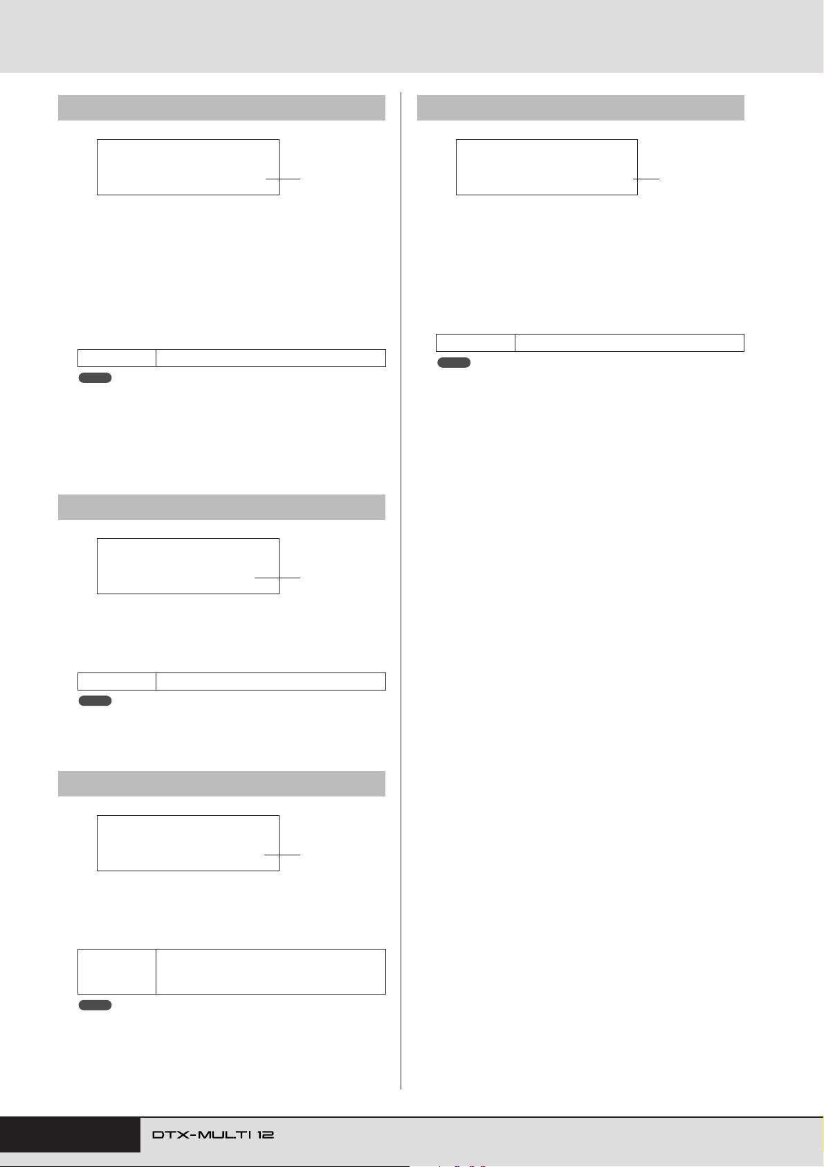
KIT Setting Area (KIT)
KIT7-3 Hi-hat Function page
KIT7-3≥≥≥<OTHER>
≥HH≥Func=hi-hat
1 Hi-hat function (HH Func)
Use this parameter to specify how a hi-hat controller connected to the HI-HAT CONTROL jack is to function.
• hi-hat ........ The hi-hat controller will function in the stan-
dard way for playing the hi-hat cymbal.
• MIDI......... When you step on the hi-hat controller, a MIDI
message is output in line with the settings made
on the Hi-hat MIDI Channel page (KIT7-4) and
the Hi-hat MIDI Type page (KIT7-5).
Settings hi-hat or MIDI
NOTE
• When this parameter is set to “hi-hat” and “on” has been selected on
the Send Hi-hat Controller page (UTIL5-3), Control Change 4 messages corresponding to the degree to which the hi-hat controller is
depressed will be sent to external MIDI devices on MIDI channel 10.
• When this parameter is set to “MIDI”, MIDI messages are sent regard-
less of the selection made on the Send Hi-hat Controller page (UTIL5-
3).
KIT7-4 Hi-hat MIDI Channel page
1
KIT7-6 Trigger Setup Link page
KIT7-6≥≥≥<OTHER>
TrgSetupLink=P01
1 Trigger setup link (TrgSetupLink)
Use this parameter to specify the trigger setup to be used
when the current kit is selected. A trigger setup can be
assigned to each different drum kit. These setups are identified using a category (P for Preset, U for User) and a number,
and you can move the cursor using the [B]/[C] buttons to
set these individually. Select “off” if the currently selected
drum kit does not need a special trigger setup.
Settings off, P01 to P05, or U01 to U10
NOTE
• If TrgSetupLink is set to “off”, the trigger setup selected on the Startup
Tr igger page (UTIL1-5) will be loaded by default whenever the DTXMULTI 12 is turned on. (See page 83.) Following this, the trigger setup
can be freely changed on the Select Trigger Setup page (TRG1). (See
page 100.)
1
KIT7-4≥≥≥<OTHER>
≥HH≥MIDI≥ch=10
1 Hi-hat MIDI channel (HH MIDI ch)
If “MIDI” has been selected on the Hi-hat Function page
(KIT7-3), use this parameter to set the MIDI channel for output of MIDI messages generated by the hi-hat controller.
Settings 1 to 16
NOTE
• If “hi-hat” has been selected on the Hi-hat Function page (KIT7-3), this
setting will be displayed as “--” and modification will not be possible.
KIT7-5 Hi-hat MIDI Type page
1
KIT7-5≥≥≥<OTHER>
HHMIDIType=CC01
1 Hi-hat MIDI type (HHMIDIType)
If “MIDI” has been selected on the Hi-hat Function page
(KIT7-3), use this parameter to set the type of MIDI message
generated by the hi-hat controller.
CC01 to CC95 (Control Change), AT (After-
Settings
NOTE
• If “hi-hat” has been selected on the Hi-hat Function page (KIT7-3), this
setting will be displayed as “---” and modification will not be possible.
touch), PBup (Pitch bend up), or PBdwn
(Pitch bend down)
1
52 Owner’s Manual
Page 53
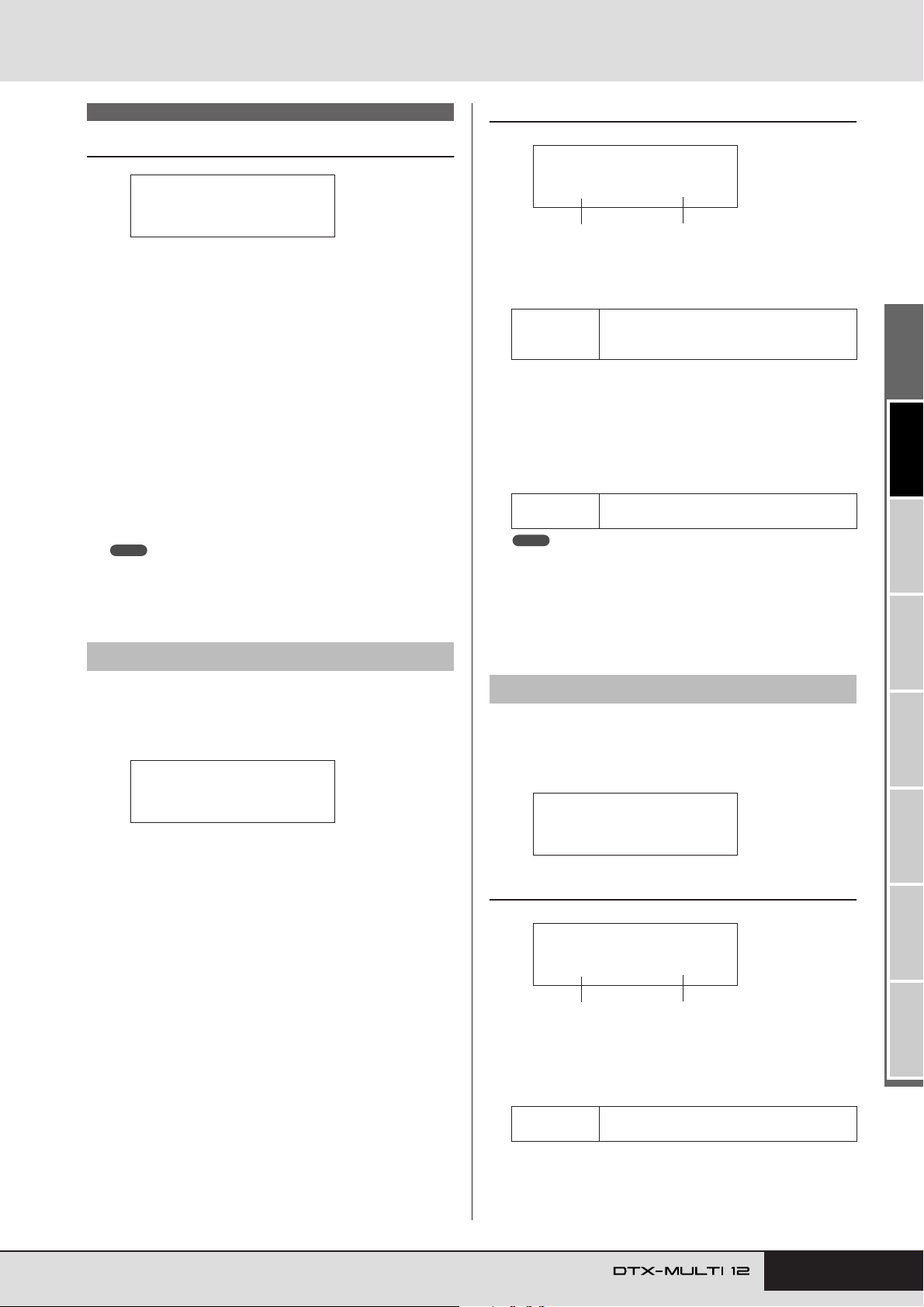
KIT Setting Area (KIT)
KIT8-1-1≥≥<Copy>
≥≥º¡≥≥≥-ß≥≥º™
1
2
KIT8-2≥≥≥≥≥<JOB>
≥≥Exchange≥Pad
KIT8-2-1≥<Exchg>
≥≥º¡≥≥≥åß≥≥º™
1
2
KIT8 JOB
Kit Management
KIT8
≥≥≥≥≥≥JOB
In the JOB section, you can perform a range of management tasks
such as copying, swapping, and initializing of kits and pads. With
the JOB page (KIT8) displayed, press the [ENTER] button to
access its five parameter-setting pages (KIT8-1 to KIT8-5). You
can use the [B]/[C] buttons to navigate between these pages.
Operations on the JOB section’s parameter-setting pages are performed as follows.
Make the required setting(s) and press the [ENTER]
1
button.
You will be asked to confirm that you wish to pro-
2
ceed.
To do so, press the [ENTER] button. Alternatively,
3
you can press the [EXIT] button to cancel the process.
NOTE
• Use the [STORE] button to open the Store Kit page and save the drum
kit in the DTX-MULTI 12’s internal memory (see page 45). (This is not
necessary when swapping kits on the Exchange Kit page (KIT8-3).)
KIT8-1-1 Copy Pad Settings page
1 Pad to be copied
Use this parameter to select the pad whose settings are to be
copied.
01 to 12, 13, 13R1, 13R2, 14 to 17, FTSW
Settings
(foot switch), HHCL (hi-hat close), or HHSP
(hi-hat splash)
B Pad to be replaced
Use this parameter to select the pad whose settings are to be
replaced. Set to “01-12” to copy settings to all of the DTXMULTI 12’s built-in pads (i.e., Pad 1 to Pad 12). You can also
set “all” to copy settings to all external pads (13, 13R1, 13R2,
14 to 17, FTSW, HHCL, and HHSP) in addition to all of the
DTX-MULTI 12’s built-in pads.
Settings
NOTE
• All information set for the pad in question and the corresponding layers
(i.e., note numbers) will be copied.
• Certain factors may require that output MIDI note numbers other than
those of the pad being copied are automatically assigned to the layers
of the pad(s) being replaced. You can confirm which output MIDI note
numbers have been set on the MIDI Note page (MIDI1-2).
01 to 12, 13, 13R1, 13R2, 14 to 17, FTSW,
HHCL, HHSP, 01 to 12, or all
KIT8-1 Copy Pad page
From the Copy Pad page, you can copy settings from one pad to
another in the currently selected drum kit. With this page displayed, press the [ENTER] button to open the Copy Pad Settings
page.
KIT8-1≥≥≥≥≥<JOB>
≥≥≥≥Copy≥Pad
KIT8-2 Exchange Pads page
From the Exchange Pads page, you can swap settings for a pair of
pads within the currently selected kit. With this page displayed,
press the [ENTER] button to open the Exchange Pads Settings
page.
KIT8-2-1 Exchange Pads Settings page
1 Exchange pad 1
B Exchange pad 2
Use these parameters to select the two pads whose settings are
to be swapped.
Settings
01 to 12, 13, 13R1, 13R2, 14 to 17, FTSW,
HHCL, or HHSP
TRIGGER ReferenceKITMIDI VOICEUTILITY WAVEPATTERN
Owner’s Manual 53
Page 54
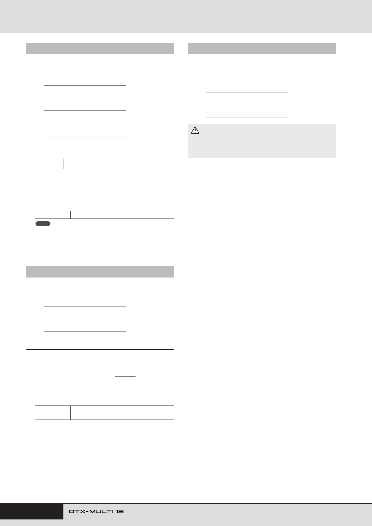
KIT Setting Area (KIT)
KIT8-3 Exchange Kits page
From the Exchange Kits page, you can swap settings for a pair of
User kits. With this page displayed, press the [ENTER] button to
open the Exchange Kits Settings page.
KIT8-3≥≥≥≥≥<JOB>
≥≥Exchange≥Kit
KIT8-3-1 Exchange Kits Settings page
KIT8-3-1≥<Exchg>
≥≥U001≥åß≥U002
1
1 Exchange kit 1
B Exchange kit 2
Use these parameters to select the two drum kits whose settings are to be swapped.
Settings U001 to U200
NOTE
• Only those settings already stored will be swapped. In addition, if drum
kits are swapped without first storing any modified settings, the
swapped settings will be overwritten with the modified settings when
the drum kit is subsequently stored.
2
KIT8-5 Initialize Kit page
From the Initialize Kit page, you can initialize the drum kit currently being edited. With the Initialize Kit page displayed, press
the [ENTER] button, and when asked to confirm that you wish to
proceed, press the [ENTER] button once again.
KIT8-5≥≥≥≥≥<JOB>
≥Initialize≥Kit
CAUTION
• When a kit is initialized, all of its parameters will be returned to their
default settings. If you would like to save a copy of the kit before initialization, perform a Store operation as described on
store the currently selected drum kit as a different User kit.
page 45 to
KIT8-4 Initialize Pad page
From the Initialize Pad page, you can initialize individual pads
from the currently selected drum kit. With this page displayed,
press the [ENTER] button to open the Initialize Pad Setting page.
KIT8-4≥≥≥≥≥<JOB>
≥Initialize≥Pad
KIT8-4-1 Initialize Pad Setting page
KIT8-4-1≥
≥≥InitPad=¡£Ω¡
1 Pad number
Use this parameter to select the pad to be initialized.
Settings
Once you have selected a pad, press the [ENTER] button, and
when asked to confirm that you wish to proceed, press the
[ENTER] button once again.
01 to 12, 13, 13R1, 13R2, 14 to 17, FTSW,
HHCL, or HHSP
1
54 Owner’s Manual
Page 55
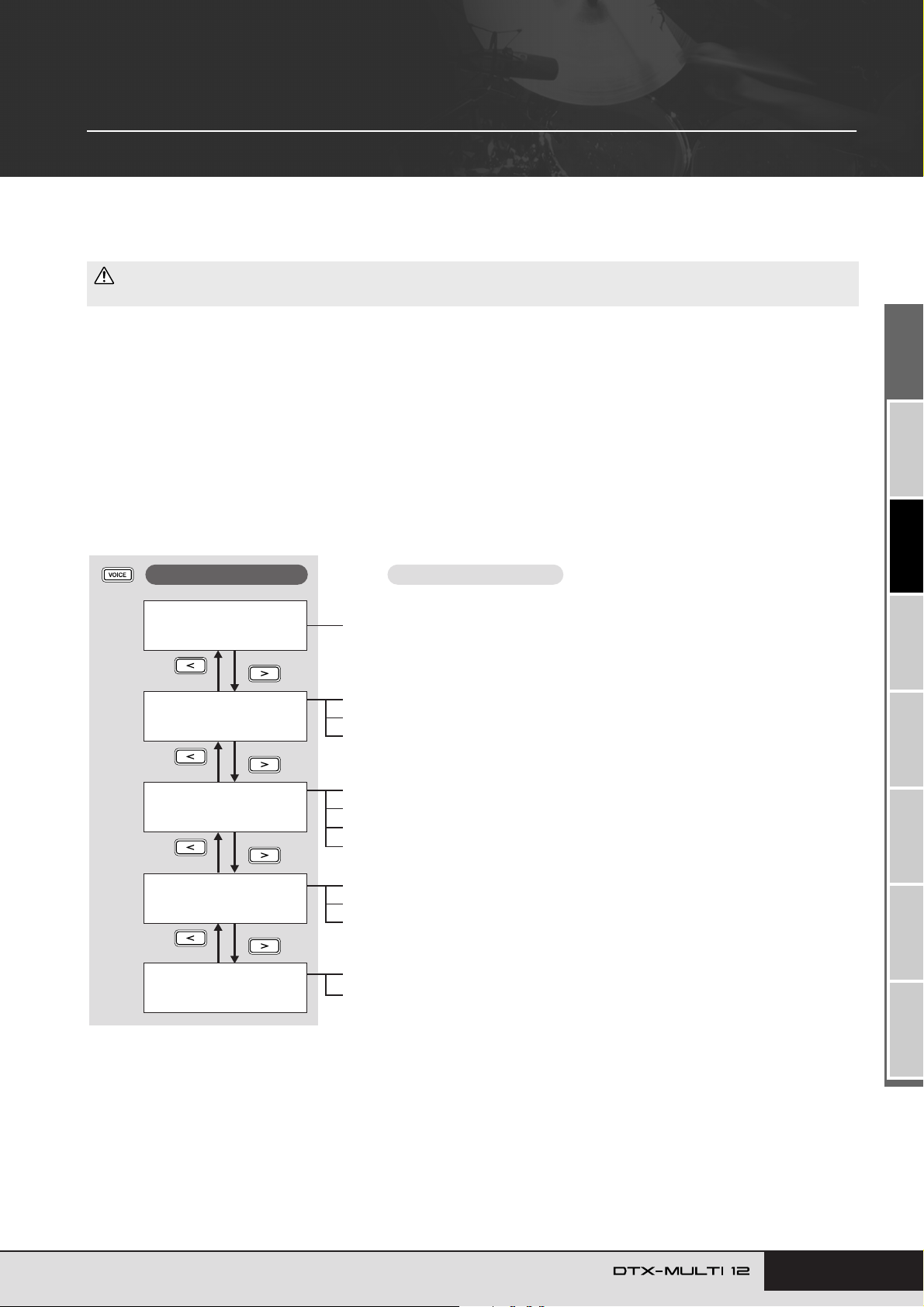
VOICE Setting Area (VCE)
This section describes the VOICE setting area, which can be accessed using the [VOICE] button. In this area, you can
select and edit the voices (i.e., preset voices, waves, and patterns) assigned to individual pads. For more information
on voices and how they work, see page 31.
CAUTION
• Be sure to store any settings that you have edited before turning off the instrument or selecting a new kit. (See page 45.)
Makeup of VOICE Setting Area
The VOICE setting area is subdivided into five different sections (VCE1 to VCE5). Use the [B]/[C] buttons to navigate between these
sections. If a section contains parameter-setting pages, the [ENTER] button will light up. Press the [ENTER] button to access these pages.
You can press the [EXIT] button to move back towards the top of the setting area.
Changes made in the VOICE setting area affect the voices assigned to pads from the currently selected kit. You should, therefore, always
select the drum kit you want to configure within the KIT setting area before entering the VOICE setting area. The top-most page within the
VOICE setting area is the Select Voice page (VCE1), and here you can assign voices (i.e., preset voices, waves, and patterns) to individual
pads and layers. On each of the parameter-setting pages within this area, furthermore, you can select the pad and/or layer to be modified.
Please note that when you store changes made to parameters within the VOICE setting area, the entire drum kit is stored.
Sections
VCE1≥-¡£Ω¡-≥≥≥≥ç
Sn001:OakCustom
VCE2≥≥≥≥≥≥≥≥≥≥≥≥
≥≥≥TUNE/OUTPUT≥
VCE3
≥≥≥≥≥≥TONE
VCE4
≥≥EFFECT≥SEND
VCE5
≥≥≥≥≥OTHER
Parameter-setting pages
Select Voice..................................................................................................... Page 56
VCE2-1 Voice Tuning page.............................................................................. Page 57
VCE2-2 Voice Volume page ............................................................................Page 57
VCE2-3 Voice Pan page.................................................................................. Page 57
VCE3-1 Attack Time page............................................................................... Page 58
VCE3-2 Decay Time page...............................................................................Page 58
VCE3-3 Release Time page............................................................................Page 58
VCE3-4 Filter page.......................................................................................... Page 58
VCE4-1 Variation Send page .......................................................................... Page 59
VCE4-2 Chorus Send page ............................................................................ Page 59
VCE4-3 Reverb Send page............................................................................. Page 59
VCE5-1 Mono/Poly page................................................................................. Page 60
VCE5-2 Alternate Group page ........................................................................Page 60
Owner’s Manual 55
TRIGGER ReferenceKITMIDI VOICEUTILITY WAVEPATTERN
Page 56
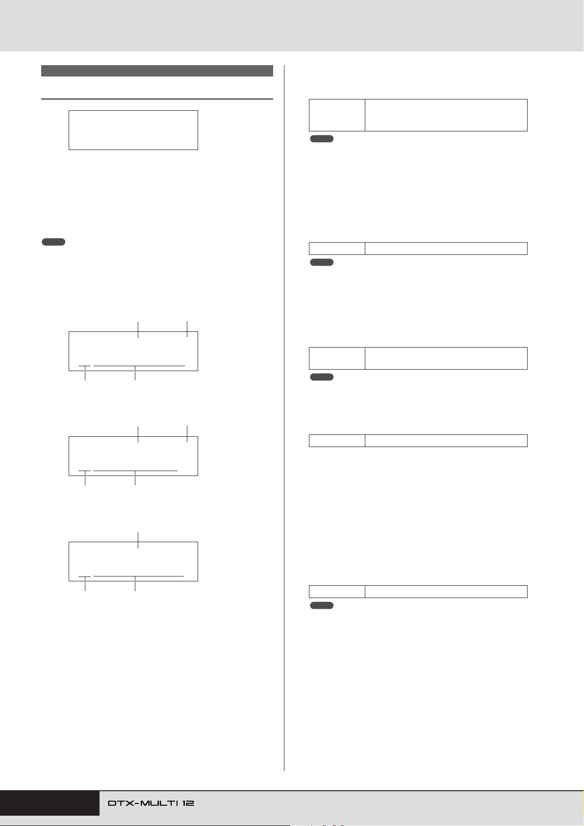
VOICE Setting Area (VCE)
VCE1
Select Voice
VCE1≥-¡£Ω¡-≥≥≥≥ç
Sn001:OakCustom
On the Select Voice page (VCE1), you can select the preset voice,
wave, or pattern that will be played when the specified pad is
struck. Alternatively, you can select a MIDI note to be played
when a pad is struck, and then assign a voice to that MIDI note
(see page 34). The applicable parameter-setting pages, parameters, and settings in the VOICE area will depend on whether a pad
number or MIDI note number is specified.
NOTE
• Certain parameters have no effect when a pattern or a MIDI note number
has been assigned to the pad in question. Their settings will be displayed
as “---” and modification will not be possible.
Assigning a voice to a pad
If the voice is not a pattern (i.e., eP or eU)
1
VCE1≥-¡£Ω¡-≥≥≥≥ç
Sn001:OakCustom
3 4
2
1 Pad number
Use this parameter to select the number of the pad or MIDI
note to be set. You can also strike a pad to select it.
01 to 12, 13, 13R1, 13R2, 14 to 17, FTSW
Settings
NOTE
•Pad 13 supports three different zones, and therefore, is assigned three
different pad numbers – namely, 13 for the head, 13R1 for rim 1, and
13R2 for rim 2.
•Pads 10 to 12 cannot be selected if “disable” has been set on the Pad
10-12 Switch page (UTIL4-3).
(foot switch), HHCL (hi-hat close), HHSP (hihat splash), C#-1, or D-1 to A#5
B Layer number
Use this parameter to select the layer to be set. Each pad can
contain up to four layers, each of which can be used to play a
preset voice or wave. For details, see page 32.
Settings A, B, C, or D
NOTE
• The maximum number of layers that can be set for any pad is 4. To add
a layer, change its setting on the MIDI Note page (MIDI1-2) from “off”
to a MIDI note number.
C Voice category
Use this parameter to specify the category of voice to be
assigned as a preset voice, preset pattern (eP), user pattern
(eU), or wave.
Settings
NOTE
•Patterns cannot be assigned to MIDI note numbers.
Kk, Sn, Tm, Cv, HH, EP, Cu, Br, In, Jp, Af, Or,
E1, E2, E3, Ml, GM, WV, eP, or eU
If the voice is a pattern (i.e., eP or eU)
1
5
VCE1≥-¡£Ω¡-≥≥≥>~
©U001:EmptyPtn
3 4
Assigning a voice to a MIDI note number
1
VCE1≥≥C#-1/≥13
Sn001:OakCustom
3 4
D Voice number: Voice name
Use these parameters to select a preset voice, pattern, or wave
from the category indicated by 3.
Settings Refer to the separate Data List booklet.
E Pattern playback mode
If a pattern has been assigned to the pad, use this parameter to
specify how it will be played.
• .............. Start/stop mode: The pattern will start to play
>
from the beginning when you strike the pad, and
it will stop the next time you strike it.
• ............ Chase mode: One successive measure will be
>~
played each time you strike the pad.
• ............ Cut-off mode: Only one pattern set to this mode
~>
can play at any time. Whenever a cut-off mode
pattern is triggered, any pattern already playing
in this mode will be automatically stopped.
Settings , ,
NOTE
• The maximum number of patterns that can play simultaneously is four.
• Demo patterns cannot be assigned to pads.
>>~~>
56 Owner’s Manual
Page 57
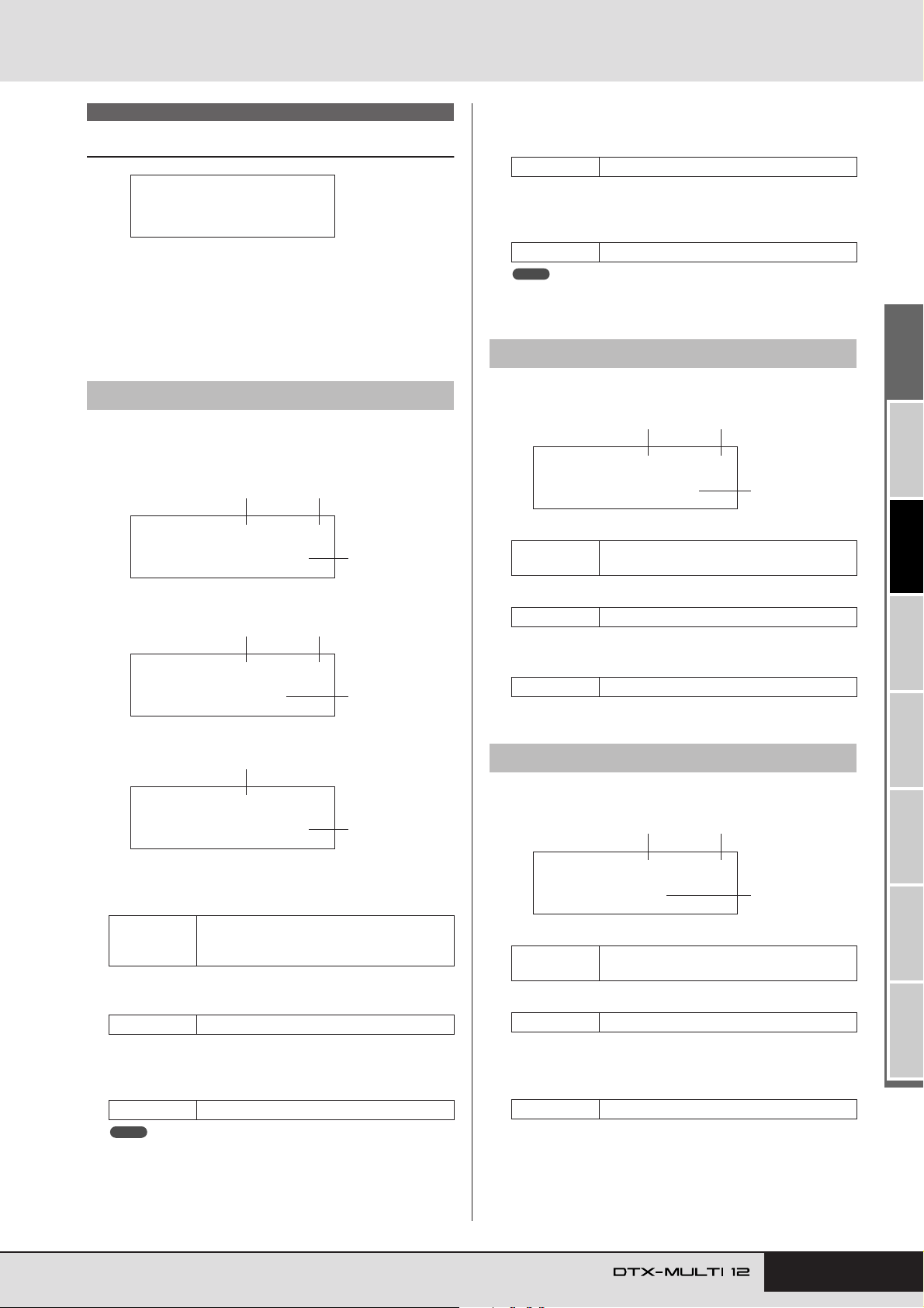
VOICE Setting Area (VCE)
VCE2-2≥-º¡-≥≥≥≥ç
≥≥≥Volume=100
3
1 2
VCE2-3≥-º¡-≥≥≥≥ç
≥≥≥≥Pan=≥C
3
1 2
VCE2 TUNE/OUTPUT
Voice Tuning, Volume & Pan
VCE2
≥≥≥TUNE/OUTPUT
In the TUNE/OUTPUT section, you can set the tuning, volume,
and stereo panning of individual voices. With the TUNE/OUTPUT page (VCE2) displayed, press the [ENTER] button to access
its three parameter-setting pages (VCE2-1 to VCE2-3). You can
use the [B]/[C] buttons to navigate between these pages.
VCE2-1 Voice Tuning page
The parameters presented on the Voice Tuning page will depend
on the type of voice assigned to the pad in question.
Drum sounds and waves (i.e., imported audio files):
1 2
VCE2-1≥-º¡-≥≥≥≥ç
≥≥≥Tune=+≥0.00
3
D Note
Use this parameter to set the pitch of the assigned voice as a
MIDI note number.
Settings C-2 to G8
E Transpose
Use this parameter to adjust the pitch of the assigned pattern
in one-semitone steps.
Settings -24 to +0 to +24
NOTE
•Patterns triggered using MIDI channels 7 to 11 cannot be transposed.
VCE2-2 Voice Volume page
On the Voice Volume page, you can set the volume of the selected
voice.
1 Pad number
Settings
01 to 12, 13, 13R1, 13R2, 14 to 17, FTSW,
HHCL, HHSP, C#-1, or D-1 to A#5
Instrument sounds (i.e., piano, guitar, etc.):
1 2
VCE2-1≥-º¡-≥≥≥≥ç
≥≥≥Note=C#-1
Patterns:
1
4
VCE2-1≥-º¡≥Transpose=+≥0
1 Pad number
Use this parameter to select the number of the pad or MIDI
note to be set.
01 to 12, 13, 13R1, 13R2, 14 to 17, FTSW
Settings
B Layer number
Use this parameter to select the layer to be set.
Settings A, B, C, or D
(foot switch), HHCL (hi-hat close), HHSP
(hi-hat splash), C#-1, or D-1 to A#5
5
B Layer number
Settings A, B, C, or D
C Volume
Use this parameter to set the volume of the selected voice.
Settings 0 to 127
VCE2-3 Voice Pan page
On the Voice Pan page, you can set the stereo panning of the
selected voice.
1 Pad number
Settings
01 to 12, 13, 13R1, 13R2, 14 to 17, FTSW,
HHCL, HHSP, C#-1, or D-1 to A#5
B Layer number
Settings A, B, C, or D
C Tuning (Tune)
Use this parameter to adjust the tuning of the assigned voice
in one-cent steps.
Settings -24.00 to +0.0 to +24.00
NOTE
• The term “cent” refers to one hundredth of a semitone (i.e., 100 cents
= 1 semitone).
C Pan
Use this parameter to set the stereo panning of the selected
voice.
Settings L63 to C to R63
Owner’s Manual 57
TRIGGER ReferenceKITMIDI VOICEUTILITY WAVEPATTERN
Page 58
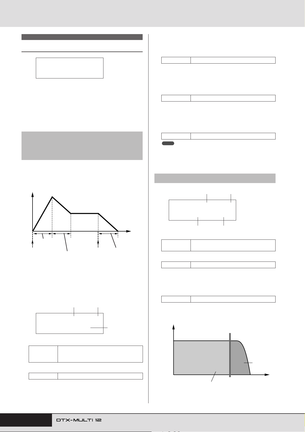
VOICE Setting Area (VCE)
VCE3 TONE
Voice Timbre
VCE3
≥≥≥≥≥≥TONE
In the TONE section, you can adjust the tone (or timbre) of the
preset voice, pattern, or wave assigned to the pad in question.
With the TONE page (VCE3) displayed, press the [ENTER] button to access its four parameter-setting pages (VCE3-1 to VCE3-
4). You can use the [B]/[C] buttons to navigate between these
pages.
VCE3-1 Attack Time page
VCE3-2 Decay Time page
VCE3-3 Release Time page
On the Attack Time, Decay Time, and Release Time pages
(VCE3-1 to VCE3-3), you can adjust the envelope of the assigned
voice as shown below.
Attack Time (VCE3-1)
C Attack time
Use this parameter to set the amount of time it takes after the
pad is struck for the assigned voice to reach its peak level.
Settings -64 to +0 to +63
Decay Time (VCE3-2)
C Decay time
Use this parameter to set the amount of time it takes the voice
to drop to a steady level after reaching its peak level.
Settings -64 to +0 to +63
Release Time (VCE3-3)
C Release time
Use this parameter to set the amount of time it takes for the
voice to fade out after sending a MIDI Note Off message.
Settings -64 to +0 to +63
NOTE
• MIDI Note Off messages are not sent for pads and layers for which
“off” is selected on the MIDI area’s Receive Key-Off page (MIDI1-5).
Therefore, the release-time setting has no effect in such a case.
VCE3-4 Filter page
Level
Time
Attack time
(VCE3-1)
Pad is struck
(Note On)
Decay time
(VCE3-2)
Note Off
Release time
(VCE3-3)
Parameter 3 from each of the pages is used to adjust a different
part of the envelope. Parameters 1 and 2 below are identical on
all three pages.
Typical Display for Attack Time (VCE3-1)
1 2
VCE3-1≥-º¡-≥≥≥≥ç
≥≥≥Attack=+≥0
3
1 2
VCE3-4≥-º¡-≥≥≥≥ç
≥Fc=+≥0≥≥Q=+≥0
3 4
1 Pad number
Settings
B Layer number
Settings A, B, C, or D
C Filter cutoff frequency (Fc)
Use this parameter to set a cutoff frequency for the low-pass
filter. Frequencies above this level will be removed from the
selected voice.
Settings -64 to +0 to +63
Low-pass filter
Volume
01 to 12, 13, 13R1, 13R2, 14 – 17, FTSW,
HHCL, HHSP, C#-1, or D-1 to A#5
Cutoff frequency (Fc)
1 Pad number
Settings
B Layer number
Settings A, B, C, or D
58 Owner’s Manual
01 to 12, 13, 13R1, 13R2, 14 to 17, FTSW
(foot switch), HHCL (hi-hat close), HHSP
(hi-hat splash), C#-1, or D-1 to A#5
Frequencies that pass
through unaffected
Frequencies
that are cut
Frequency
(or pitch)
Page 59
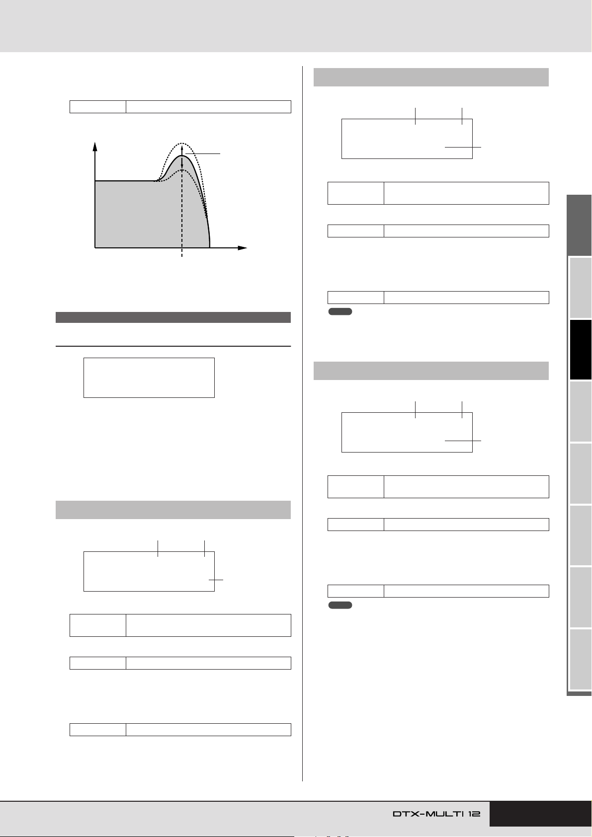
VOICE Setting Area (VCE)
VCE4-2≥-º¡-≥≥≥≥ç
≥≥ChoSend=127
3
1 2
VCE4-3≥-º¡-≥≥≥≥ç
≥≥RevSend=≥50
3
1 2
D Resonance (Q)
Use this parameter to change the timbre of the voice by boosting frequencies around the cutoff frequency.
Settings -64 to +0 to +63
Level
Resonance (Q)
Cutoff frequency
Frequency
VCE4 EFFECT SEND
Effect Send Levels
VCE4-2 Chorus Send page
1 Pad number
Settings
01 to 12, 13, 13R1, 13R2, 14 to 17, FTSW,
HHCL, HHSP, C#-1, or D-1 to A#5
B Layer number
Settings A, B, C, or D
C Chorus send level (ChoSend)
Use this parameter to specify how much of the sound produced by the layer indicated by 2 will be sent to the Chorus
effect.
Settings 0 to 127
NOTE
• The chorus send level for the entire kit can be adjusted on the KIT
area’s Chorus Send page (KIT3-1).
VCE4
≥≥EFFECT≥SEND
In the EFFECT SEND section, you can adjust the degree to which
the DTX-MULTI 12’s built-in Variation, Chorus, and Reverb
effects are applied to individual voices. With the EFFECT SEND
page (VCE4) displayed, press the [ENTER] button to access its
three parameter-setting pages (VCE4-1 to VCE4-3). You can use
the [B]/[C] buttons to navigate between these pages.
VCE4-1 Variation Send page
1 2
VCE4-1≥-º¡-≥≥≥≥ç
Var=127(Dry=≥≥0)
1 Pad number
Settings
B Layer number
Settings A, B, C, or D
C Variation send level (Var)
Use this parameter to specify how much of the sound produced by the layer indicated by 2 will be sent to the Variation
effect.
Settings 0 to 127
01 to 12, 13, 13R1, 13R2, 14 to 17, FTSW,
HHCL, HHSP, C#-1, or D-1 to A#5
3
VCE4-3 Reverb Send page
1 Pad number
Settings
01 to 12, 13, 13R1, 13R2, 14 to 17, FTSW,
HHCL, HHSP, C#-1, or D-1 to A#5
B Layer number
Settings A, B, C, or D
C Reverb send level (RevSend)
Use this parameter to specify how much of the sound produced by the layer indicated by 2 will be sent to the Reverb
effect.
Settings 0 to 127
NOTE
• The reverb send level for the entire kit can be adjusted on the KIT
area’s Reverb Send page (KIT3-2).
TRIGGER ReferenceKITMIDI VOICEUTILITY WAVEPATTERN
Owner’s Manual 59
Page 60
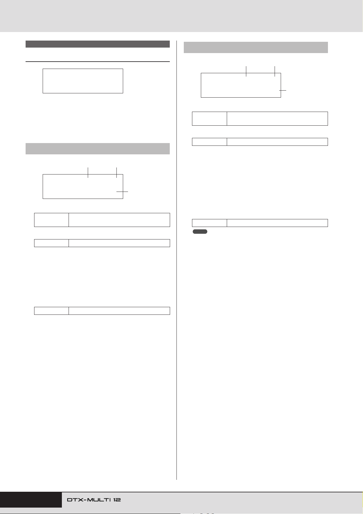
VOICE Setting Area (VCE)
VCE5 OTHER
Other Voice-Related Settings
VCE5
≥≥≥≥≥OTHER
With the OTHER page (VCE5) displayed, press the [ENTER]
button to access its two parameter-setting pages (VCE5-1 and
VCE5-2). You can use the [B]/[C] buttons to switch between
these pages.
VCE5-1 Mono/Poly page
1 2
VCE5-1≥-º¡-≥≥≥≥ç
≥Mono/Poly=poly
1 Pad number
Settings
B Layer number
Settings A, B, C, or D
C Mono/Poly
Use this parameter to specify how overlapping sounds from
the same pad or layer will be treated.
• mono......... When two overlapping sounds are produced by
• poly........... No such restriction is applied and all overlap-
Settings mono or poly
01 to 12, 13, 13R1, 13R2, 14 to 17, FTSW,
HHCL, HHSP, C#-1, or D-1 to A#5
striking the same pad, the latter sound is given
priority and the earlier sound is silenced.
ping sounds are output.
3
VCE5-2 Alternate Group page
1 2
VCE5-2≥-º¡-≥≥≥≥ç
AltGroup=≥≥≥≥off
1 Pad number
Settings
B Layer number
Settings A, B, C, or D
C Alternate group (AltGroup)
Using this parameter, you can assign voices to alternate
groups (i.e., monophonic sets of pads, only one of which can
be producing a sound at any time). If you do not want various
individual voices to be played together, they should be
assigned to the same alternate group. Whenever voices from
the same alternate group are triggered by playing the instrument, the latter voice is given priority and the earlier sound is
silenced. Set this parameter to “off” if you do not want to
assign an alternate group.
Settings off, hhOpen, hhClose, or 1 to 124
NOTE
• The “hhOpen” and “hhClose” alternate groups operate in a special
way: If a voice from the “hhClose” group is triggered after a voice from
the “hhOpen” group, the hhOpen voice is silenced and only the
hhClose voice is played. No silencing of the earlier sound is performed
for any other triggering sequence (for example, hhOpen followed by
hhOpen; hhClose followed by hhOpen; or hhClose followed by
hhClose).
01 to 12, 13, 13R1, 13R2, 14 to 17, FTSW,
HHCL, HHSP, C#-1, or D-1 to A#5
3
60 Owner’s Manual
Page 61
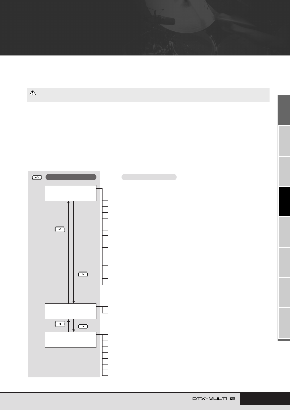
MIDI Setting Area (MIDI)
This section describes the MIDI setting area, which can be accessed using the [MIDI] button. In this area, you can set
MIDI-related parameters on an individual-kit basis. In addition, layer settings for each pad (i.e., the number of layers
and the way in which they play) are also configured within the MIDI setting area. For more information on the functions
setup using this setting area, see page 34.
CAUTION
• Be sure to store any settings that you have edited before turning off the instrument or selecting a new kit. (See page 45.)
Structure of MIDI Setting Area
The MIDI setting area is subdivided into three different sections (MIDI1 to MIDI3). Use the [B]/[C] buttons to navigate between these
sections. If a section contains parameter-setting pages, the [ENTER] button will light up. Press the [ENTER] button to access these pages.
You can press the [EXIT] button to move back towards the top of the setting area. MIDI parameters set within this area are stored on an
individual-kit basis; therefore, you should always select the drum kit you want to configure within the KIT setting area before entering the
MIDI setting area. Parameters within the MIDI MESSAGE section (MIDI1) affect individual pads, which can be selected on-screen or by
striking them. Meanwhile, parameters within the TG/MIDI SWITCH section (MIDI2) and the OTHER section (MIDI3) affect individual
MIDI channels, which can be selected on-screen.
Sections
MIDI1≥-º¡MessageType=note
MIDI2≥≥≥≥≥≥≥≥≥≥≥
≥TG/MIDI≥SWITCH
Parameter-setting pages
The parameter-setting pages that make up the MIDI MESSAGE section will depend
on the type of MIDI message selected on the Select Message Type page (MIDI1).
• Pages when MessageType is set to “note”:
MIDI1-1 Playing Mode page............................................................................ Page 62
MIDI1-2 MIDI Note page ................................................................................. Page 63
MIDI1-3 MIDI Channel page ...........................................................................Page 63
MIDI1-4 Gate Time page................................................................................. Page 64
MIDI1-5 Receive Key-Off page .......................................................................Page 64
MIDI1-6 Velocity Limits page........................................................................... Page 64
MIDI1-7 Trigger Velocity page .........................................................................Page 64
MIDI1-8 Trigger Polyphony page..................................................................... Page 65
MIDI1-9 Trigger Alternate Group page ............................................................ Page 65
• Pages when MessageType is set to “CC”:
MIDI1-1 Control Change Number & Value page .............................................Page 65
MIDI1-2 MIDI Channel page ...........................................................................Page 65
• Pages when MessageType is set to “PC”:
MIDI1-1 Program Change page ...................................................................... Page 66
MIDI1-2 MIDI Channel page ...........................................................................Page 66
• No pages are accessible when MessageType is set to
“strt”, “cont”, or “stop”.
MIDI2-1 Tone Generator Switch page ............................................................. Page 66
MIDI2-2 External MIDI Switch page ................................................................ Page 66
MIDI3≥≥≥≥≥≥≥≥≥≥≥
≥≥≥≥≥OTHER
MIDI3-1 Transmit page.................................................................................... Page 67
MIDI3-2 Volume page...................................................................................... Page 67
MIDI3-3 Pan page ........................................................................................... Page 67
MIDI3-4 Program Change page ...................................................................... Page 67
MIDI3-5 Variation Send Level page................................................................. Page 68
MIDI3-6 Chorus Send Level page................................................................... Page 68
MIDI3-7 Reverb Send Level page ...................................................................Page 68
MIDI3-8 CC Number & Value page .................................................................Page 68
Owner’s Manual 61
TRIGGER ReferenceKITMIDI VOICEUTILITY WAVEPATTERN
Page 62
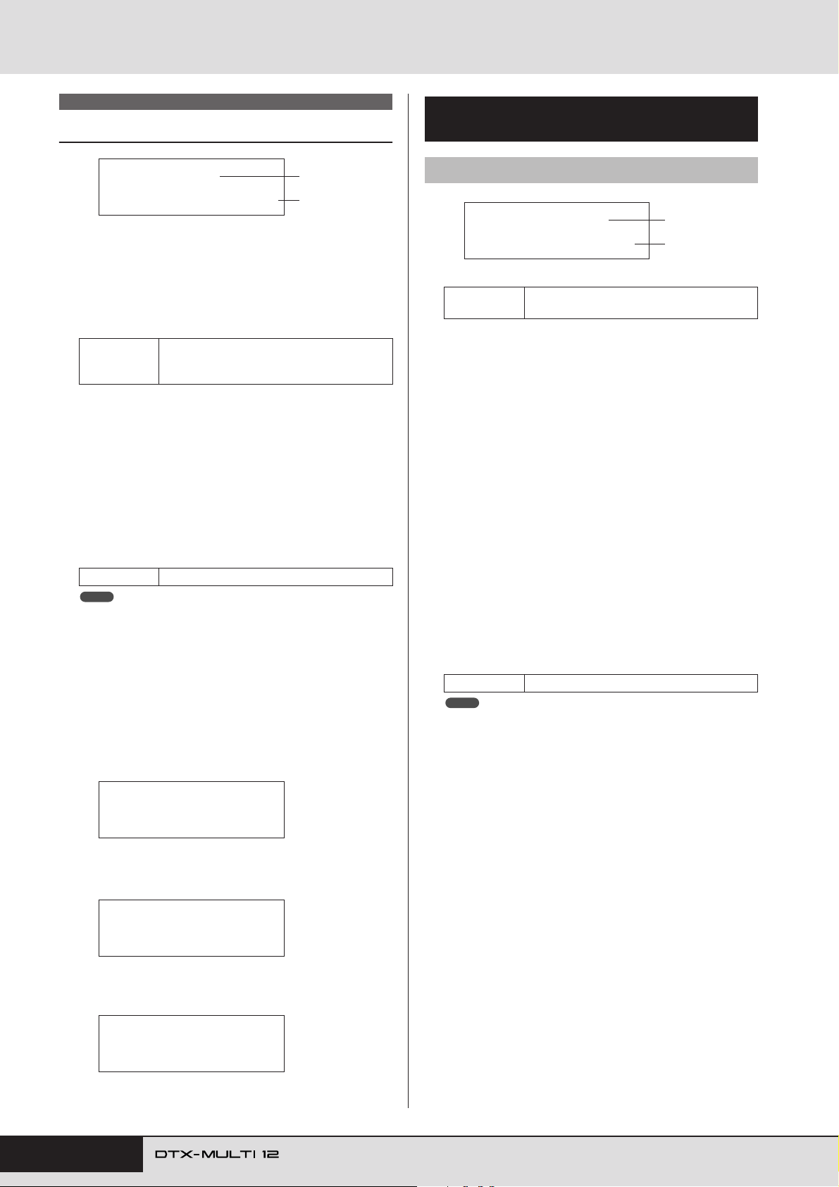
MIDI Setting Area (MIDI)
MIDI1
Select Message Type
MIDI1≥-º¡MessageType=note
When you press the [MIDI] button, a page for selecting a MIDI
message type (MIDI1) will be displayed. On this page, you can
select the type of MIDI message to be assigned to each pad.
1 Pad number
Use this parameter to select the pad to be set. You can also
strike a pad to select it.
01 to 12, 13, 13R1, 13R2, 14 to 17, FTSW
Settings
B Message type
Use this parameter to set the type of MIDI message that will
be sent whenever the pad indicated by 1 is struck.
• note ........... A MIDI note will be sent. Use this setting if you
•CC............ A Control Change message will be sent.
•PC............. A Program Change message will be sent.
• strt............. A SysEx FA Start command will be sent.
• cont ........... A SysEx FB Continue command will be sent.
• stop ...........A SysEx FC Stop command will be sent.
Settings note, CC, PC, strt, cont, or stop
NOTE
• “note” type messages are sent simultaneously to the DTX-MULTI 12’s
internal tone generator and to connected external MIDI devices.
• Message types other than “note” are sent only to connected external
MIDI devices.
The parameter-setting pages that can be accessed
within the MIDI1 section will depend on the type of
MIDI message selected.
•Parameter-setting pages for “note” messages are
explained on this page.
(foot switch), HHCL (hi-hat close), or HHSP
(hi-hat splash)
want to produce a sound whenever you strike the
pad.
1
2
Parameter-Setting Pages for
“note” Messages
MIDI1-1 Playing Mode page
MIDI1-1≥-º¡≥Mode=alternate
1 Pad number
Settings
B Playing mode
Use this parameter to set Stack, Alternate, or Hold as the playing mode for the pad indicated by 1. Some typical applications of these modes are explained on the following page.
• stack ......... When Stack mode is selected, all notes assigned
• alternate.... When Alternate mode is selected, the notes
• hold .......... When Hold mode is selected, the notes assigned
Settings stack, alternate, or hold
NOTE
• If no note numbers have been assigned to any of the pad’s layers (A to
D) on the MIDI Note page (MIDI1-2), this setting will be displayed as “-
--” and modification will not be possible.
01 to 12, 13, 13R1, 13R2, 14 to 17, FTSW,
HHCL, or HHSP
to the pad are triggered simultaneously. For
example, you can use this mode to produce
chords or to trigger multiple preset voices or
waves with a single strike. To produce just one
sound, select this mode and assign only one
voice to the pad.
assigned to the pad are played individually in
turn each time it is struck. For example, you can
use this mode to produce a different sound each
time you strike the pad.
to the pad are alternately turned on and off each
time it is struck. If, for example, a sustained
sound has been assigned, the first strike of the
pad will turn it on, the next strike will turn it off,
and so on.
1
2
MIDI1≥-º¡MessageType=note
•Parameter-setting pages for “CC” messages are
explained on page 65.
MIDI1≥-º¡MessageType=CC
•Parameter-setting pages for “PC” messages are
explained on page 66.
MIDI1≥-º¡MessageType=PC
62 Owner’s Manual
Page 63
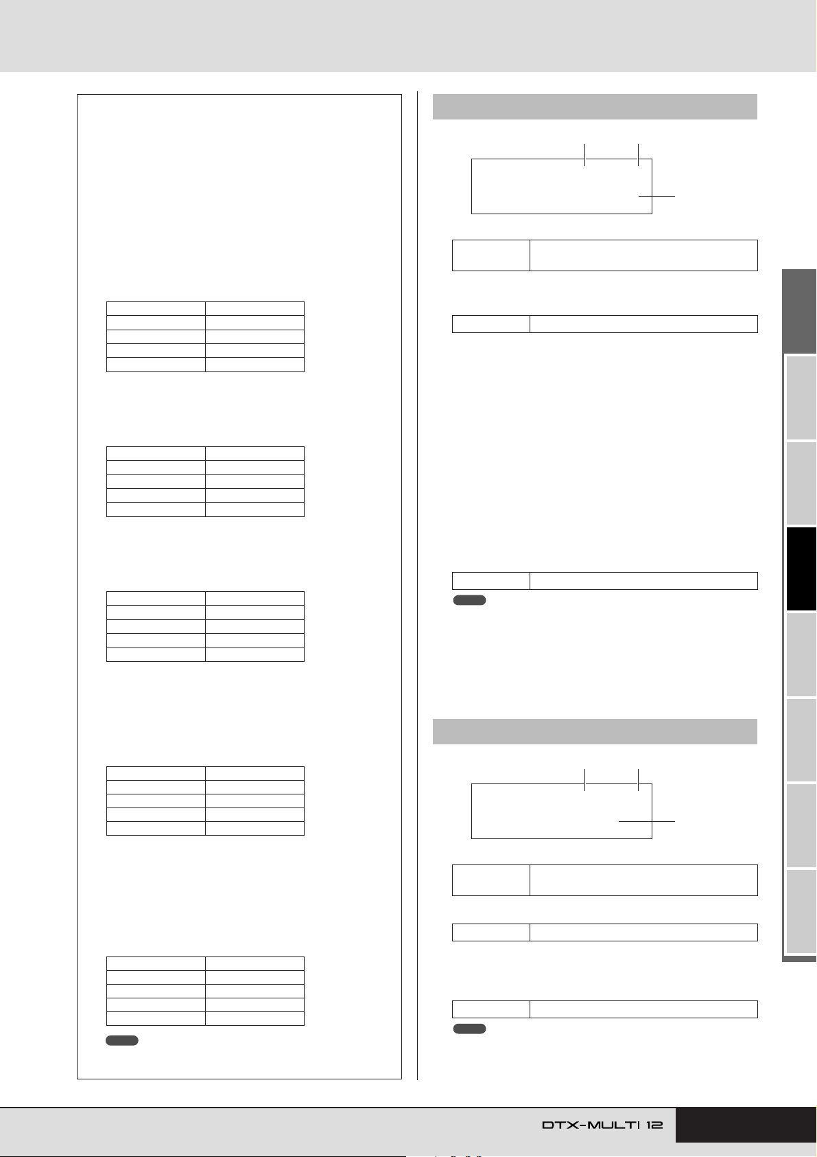
MIDI Setting Area (MIDI)
MIDI1-2≥-º¡-≥≥≥ç
Note=*≥C#-1/≥13
3
1 2
MIDI1-3≥-º¡-≥≥≥ç
≥≥≥MIDI≥Ch=10
3
1 2
Typical Uses of Stack, Alternate, and
Hold Modes
Using the Playing Mode page (MIDI1-1), you can select the
way in which a pad’s four layers will be played. For example,
pads can be setup to produce a chord by playing multiple layers at the same time or to play a different layer on each successive strike. The following are typical examples of how these
modes can be used.
● Playing just one sound when a pad is struck
Select “stack” on the Playing Mode page (MIDI1-1), and
assign a MIDI note to Layer A only on the MIDI Note
page (MIDI1-2).
Layer Note number
AD1
B off
C off
D off
●
Playing two sounds simultaneously when a pad is struck
Select “stack” on the Playing Mode page (MIDI1-1), and
assign a different MIDI note to both Layer A and Layer B
on the MIDI Note page (MIDI1-2).
Layer Note number
AD1
BE2
C off
D off
●
Playing two sounds alternately each time a pad is struck
Select “alternate” on the Playing Mode page (MIDI1-1),
and assign a different MIDI note to Layers A and B on the
MIDI Note page (MIDI1-2).
Layer Note number
AD1
BE2
C off
D off
● Playing Layer A, then silencing it, playing Layer C, then
silencing it, playing Layer A… and so on each time a
pad is struck
Select “alternate” on the Playing Mode page (MIDI1-1),
and assign a MIDI note or “skip” to Layers A through D
on the MIDI Note page (MIDI1-2) as follows.
Layer Note number
AD1
B skip
CE2
D skip
MIDI1-2 MIDI Note page
1 Pad number
Settings
01 to 12, 13, 13R1, 13R2, 14 to 17, FTSW,
HHCL, or HHSP
B Layer number
Use this parameter to select the layer you want to set.
Settings A, B, C, or D
C Note
Use this parameter to select a MIDI note to be sent by the
layer indicated by 2. You can also choose either of the following two special settings.
•off ..............Regardless of the setting made on the Playing
Mode page (MIDI1-1), no MIDI note will be
sent when the pad is struck.
• skip............If “alternate” has been selected on the Playing
Mode page (MIDI1-1), this layer will be
skipped. In other words, no MIDI note will be
sent when it is this layer’s turn to play. Alternatively, if “stack” or “hold” has been set on the
Playing Mode page (MIDI1-1), this setting has
the same effect as “off” above (i.e., no MIDI
note will be sent for this layer).
Settings off, C#-2/1 to F#8/126, or skip
NOTE
• Notes outside the range covered by General MIDI are displayed in
parentheses – for example, “(C#-2/1)”.
• Notes on MIDI channel 10 having already been assigned to a layer will
be displayed with an asterisk in front of them – for example, “*C3”. If
you change the note setting for a pad indicated in this way, the note
setting for the other pad will also be changed in the same way .
MIDI1-3 MIDI Channel page
● Playing three held sounds simultaneously when a pad
is struck, and silencing them the next time it is struck
Select “hold” on the Playing Mode page (MIDI1-1), and
assign MIDI notes to Layers A through C on the MIDI
Note page (MIDI1-2) as follows. In addition, select “on”
for Layers A through C on the Receive Key-Off page
(MIDI1-5).
Layer Note number
AC3
BE3
CG3
D off
NOTE
• If a note on MIDI channel 10 is assigned, be sure to select “on” for
Layers A through C on the Receive Key-Off page (MIDI1-5).
1 Pad number
Settings
01 to 12, 13, 13R1, 13R2, 14 to 17, FTSW,
HHCL, or HHSP
B Layer number
Settings A, B, C, or D
C MIDI channel (MIDI Ch)
Use this parameter to set the MIDI channel for MIDI notes
sent for the layer indicated by 2.
Settings 1 to 16
NOTE
• If no note number has been assigned to any of the pad’s layers (A to
D) on the MIDI Note page (MIDI1-2), this setting will be displayed as “-
--” and modification will not be possible.
Owner’s Manual 63
TRIGGER ReferenceKITMIDI VOICEUTILITY WAVEPATTERN
Page 64
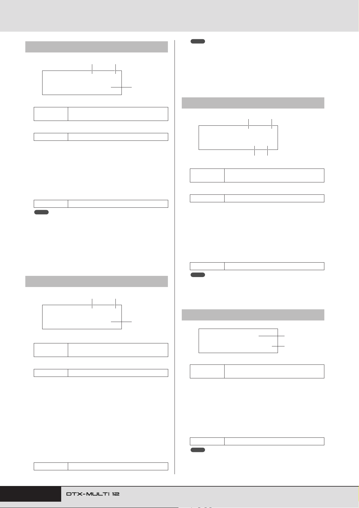
MIDI Setting Area (MIDI)
MIDI1-4 Gate Time page
MIDI1-4≥-º¡-≥≥≥ç
≥GateTime=0.0s
1 2
NOTE
• If no note numbers have been assigned to any of the pad’s layers (A to
D) on the MIDI Note page (MIDI1-2), this setting will be displayed as “-
--” and modification will not be possible.
• Sending of MIDI Note Off messages is automatically turned on whenever a MIDI Channel other than 10 has been selected on the MIDI
Channel page (MIDI1-3). In such a case, therefore, this setting will be
displayed as “---” and modification will not be possible.
3
1 Pad number
Settings
01 to 12, 13, 13R1, 13R2, 14 to 17, FTSW,
HHCL, or HHSP
B Layer number
Settings A, B, C, or D
C Gate time
Use this parameter to set a gate time for MIDI notes sent for
the layer indicated by 2. A MIDI Note On message is sent
when a pad is struck, and the corresponding Note Off message is sent a short time later. The duration between sending
of these signals is referred to as the “gate time”, and by
adjusting this setting, you can control the duration of MIDI
notes.
Settings 0.0s to 9.9s
NOTE
• If no note numbers have been assigned to any of the pad’s layers (A to
D) on the MIDI Note page (MIDI1-2), this setting will be displayed as “-
--” and modification will not be possible.
• If “hold” has been selected on the Playing Mode page (MIDI1-1), this
setting will be displayed as “---” and modification will not be possible.
• MIDI Note Off signals are not sent for pads set to “off” on the Receive
Key-Off page (MIDI1-5). If you want to set a gate time, therefore, be
sure to set RcvKeyOff to “on”.
MIDI1-5 Receive Key-Off page
1 2
MIDI1-6 Velocity Limits page
1 2
MIDI1-6≥-º¡-≥≥≥ç
VelLimit=≥≥0-127
3 4
1 Pad number
Settings
B Layer number
Settings A, B, C, or D
C Velocity lower limit
D Velocity upper limit
Use these parameters to set the range of velocities that will
cause the layer indicated by 2 to send a MIDI note message.
The term “velocity” refers to the speed (or power) with which
a pad is struck. By setting upper and lower limits using these
parameters, you can prevent sounds from being produced
when the pad is struck too hard or too soft.
Settings 0 to 127
NOTE
• If no note numbers have been assigned to any of the pad’s layers (A to
D) on the MIDI Note page (MIDI1-2), these settings will be displayed
as “---” and modification will not be possible.
01 to 12, 13, 13R1, 13R2, 14 to 17, FTSW,
HHCL, or HHSP
MIDI1-5≥-º¡-≥≥≥ç
≥RcvKeyOff=off
1 Pad number
Settings
B Layer number
Settings A, B, C, or D
C Receive key-off (RcvKeyOff)
Use this parameter to set whether or not MIDI Note Off messages will be sent for the layer indicated by 2. Most drum
voices are one-shot sounds that decay over time until they
become silent; therefore, MIDI Note Off messages are not
needed to stop them. As such, this parameter should normally
be set to “off”. If, however, a non-decaying sound is assigned
to a pad or layer, you can ensure that the required MIDI Note
Off message is sent by setting this parameter to “on”. In addition, you can adjust the amount of time that passes between
striking of the pad and sending MIDI Note Off messages
using the Gate Time page (MIDI1-4).
Settings off or on
01 to 12, 13, 13R1, 13R2, 14 to 17, FTSW,
HHCL, or HHSP
3
MIDI1-7 Trigger Velocity page
MIDI1-7≥-º¡-≥≥≥
TrgVel=variable
1
2
1 Pad number
Settings
01 to 12, 13, 13R1, 13R2, 14 to 17, FTSW,
HHCL, or HHSP
B Trigger velocity (TrgVel)
Use this parameter to control the velocity value of MIDI notes
to be sent whenever the pad indicated by 1 is struck.
•variable..... MIDI velocity values will reflect the strength
with which the pad is struck.
•1 – 127...... MIDI notes are sent with this fixed velocity
value, regardless of how hard or soft the pad is
struck.
Settings variable or 1 to 127
NOTE
• If no note numbers have been assigned to any of the pad’s layers (A to
D) on the MIDI Note page (MIDI1-2), this setting will be displayed as “-
--” and modification will not be possible.
• No sound will be produced if TrgVel 2 is set to a value outside the limits set on the Velocity Limits page (MIDI1-6).
64 Owner’s Manual
Page 65
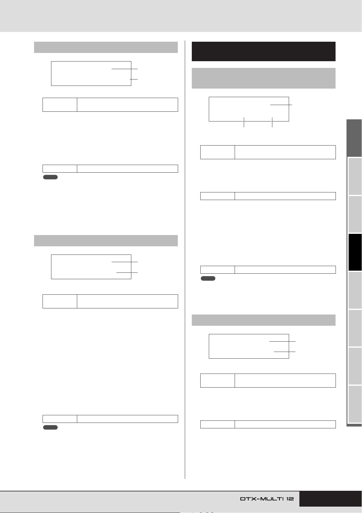
MIDI Setting Area (MIDI)
MIDI1-1≥-º¡CCNo=≥7/Val=VARI
1
23
MIDI1-2≥-º¡≥≥≥MIDI≥Ch=10
1
2
MIDI1-8 Trigger Polyphony page
MIDI1-8≥-º¡TrgMonoPoly=poly
1
2
1 Pad number
Settings
01 to 12, 13, 13R1, 13R2, 14 to 17, FTSW,
HHCL, or HHSP
B Trigger mono/poly (TrgMonoPoly)
Use this parameter to control what happens when the pad
indicated by 1 is struck repeatedly.
• mono ........ The previous sound will be stopped before a
new sound starts.
• poly .......... Previous sounds will continue to play when a
new sound starts.
Settings mono or poly
NOTE
• If no note numbers have been assigned to any of the pad’s layers (A to
D) on the MIDI Note page (MIDI1-2), this setting will be displayed as “-
--” and modification will not be possible.
• MIDI Note Off messages are not sent when “off” has been selected on
the Receive Key-Off page (MIDI1-5). If you want to set trigger monophony, therefore, be sure to set this parameter to “on”. This will ensure
that Note Off messages are sent to prevent overlapping voices.
MIDI1-9 Trigger Alternate Group page
MIDI1-9≥-º¡-≥≥
TrgAltGrp=off
1
2
1 Pad number
Settings
01 to 12, 13, 13R1, 13R2, 14 to 17, FTSW,
HHCL, or HHSP
Parameter-Setting Pages for
“CC” Messages
MIDI1-1 Control Change Number &
Value page
1 Pad number
Settings
B Control change number (CCNo)
Use this parameter to set the type of MIDI Control Change
message to be sent whenever the pad indicated by 1 is
struck.
Settings 1 to 95
C Control change value (Val)
Use this parameter to set a value for the MIDI Control Change
message to be sent whenever the pad indicated by 1 is
struck.
•VARI .........The control change value will depend on how
•0 – 127 ......Control change messages are sent with this fixed
Settings VARI or 0 to 127
NOTE
• Before setting Val 3 to “VARI”, it will be necessary to access the Trigger Velocity page (MIDI1-7) with Message Type=note (MIDI1) and to
set the TrgVel parameter to “variable”.
01 to 12, 13, 13R1, 13R2, 14 to 17, FTSW,
HHCL, or HHSP
hard the pad is struck.
value, regardless of how hard or soft the pad is
struck.
B Trigger alternate group (TrgAltGrp)
Use this parameter to assign the pad indicated by 1 to an
alternate group if so required. Alternate groups are monophonic sets of pads, and therefore, only one pad from an alternate
group can be producing a sound at any time. If a pad is struck
while another pad from the same alternate group is already
producing a sound, a MIDI Note Off message will be sent for
the first pad together with the MIDI Note On message for the
second. In order to use trigger alternate groups with voices
played on MIDI channel 10, the sending of MIDI Note Off
messages must be enabled by selecting “on” for RcvKeyOff
on the Receive Key-Off page (MIDI1-5). Up to 32 trigger
alternate groups can be setup on your DTX-MULTI 12. If
there is no need for a pad to be assigned to a trigger alternate
group, you can set this parameter to “off”.
Settings off or 1 to 32
NOTE
• If no note numbers have been assigned to any of the pad’s layers (A to
D) on the MIDI Note page (MIDI1-2), this setting will be displayed as “-
--” and modification will not be possible.
• MIDI Note Off messages are not sent when “off” has been set on the
Receive Key-Off page (MIDI1-5). If you want to use trigger alternate
groups, therefore, be sure to set this parameter to “on”. This will ensure
that Note Off messages are sent to prevent overlapping voices.
MIDI1-2 MIDI Channel page
1 Pad number
Settings
01 to 12, 13, 13R1, 13R2, 14 to 17, FTSW,
HHCL, or HHSP
B MIDI channel (MIDI Ch)
Use this parameter to set a MIDI channel for the Control
Change messages to be sent whenever the pad indicated by 1
is struck.
Settings 1 to 16
Owner’s Manual 65
TRIGGER ReferenceKITMIDI VOICEUTILITY WAVEPATTERN
Page 66
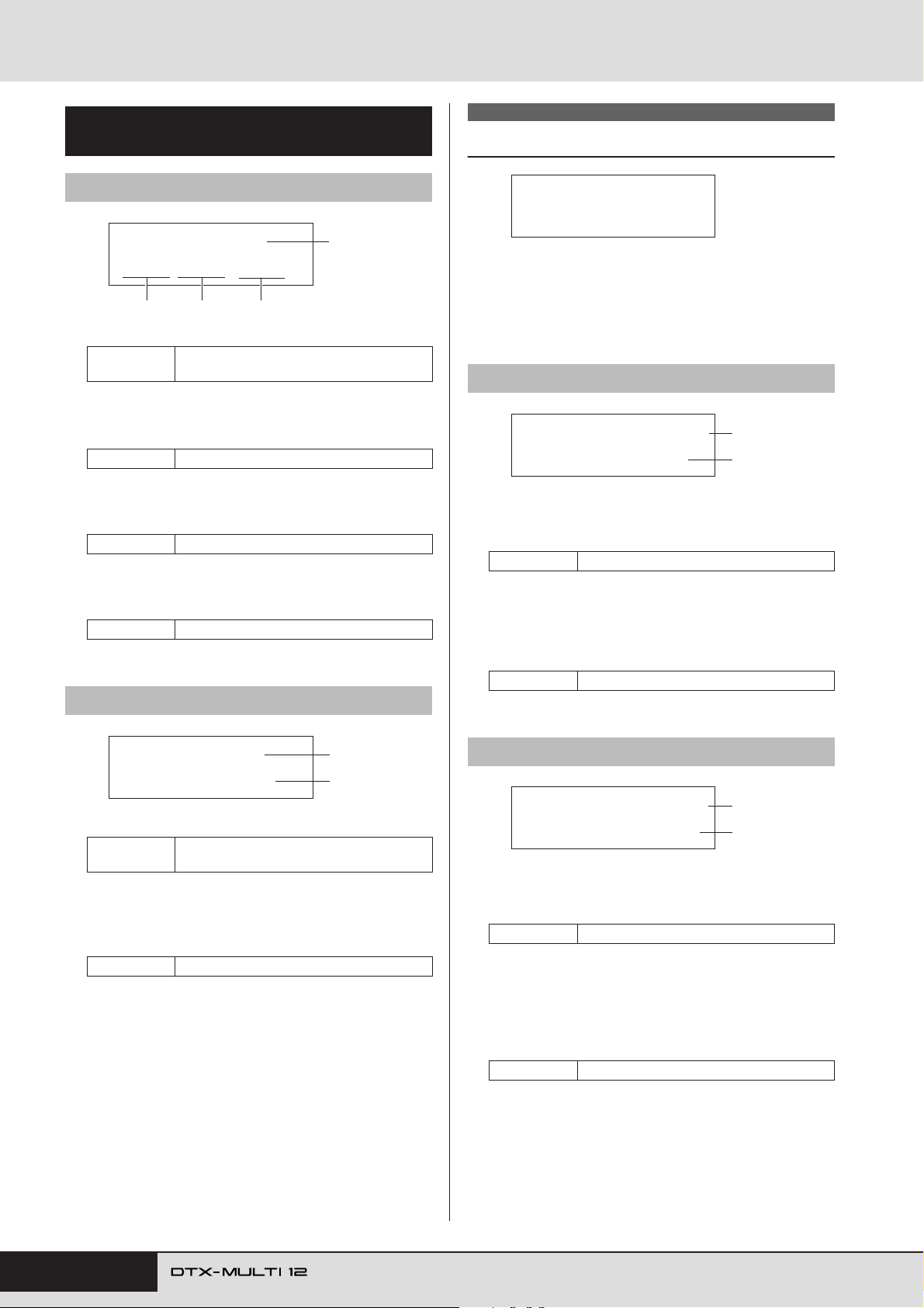
MIDI Setting Area (MIDI)
Parameter-Setting Pages for
“PC” Messages
MIDI1-1 Program Change page
MIDI1-1≥-º¡-
1
M000/L000/PC001
32 4
1 Pad number
Settings
B Bank select MSB (M)
Use this parameter to set a bank-select MSB value to be sent
whenever the pad indicated by 1 is struck.
Settings 000 to 127
C Bank select LSB (L)
Use this parameter to set a bank-select LSB value to be sent
whenever the pad indicated by 1 is struck.
Settings 000 to 127
D Program change (PC)
Use this parameter to set a program-change number to be sent
whenever the pad indicated by 1 is struck.
Settings 001 to 128
MIDI1-2 MIDI Channel page
01 to 12, 13, 13R1, 13R2, 14 to 17, FTSW,
HHCL, or HHSP
MIDI2 TG/MIDI SWITCH
MIDI Destination Switches
MIDI2
≥TG/MIDI≥SWITCH
With the TG/MIDI SWITCH page (MIDI2) displayed, press the
[ENTER] button to access its two parameter-setting pages
(MIDI2-1, MIDI2-2). You can use the [B]/[C] buttons to switch
between these pages.
MIDI2-1 Tone Generator Switch page
MIDI2-1≥≥≥≥≥Ch≥1
≥TG≥Switch=off
1 MIDI channel (Ch)
Use this parameter to select the MIDI channel (1 to 16) to be
set.
Settings 1 to 16
B Tone generator switch (TGSwitch)
Use this parameter to indicate whether MIDI messages produced by playing pads and changing drum kits should be sent
to the internal tone generator. (Choose “on” to send to the
tone generator.)
Settings off or on
1
2
MIDI1-2≥-º¡≥≥≥MIDI≥Ch=10
1
2
1 Pad number
Settings
01 to 12, 13, 13R1, 13R2, 14 to 17, FTSW,
HHCL, or HHSP
B MIDI channel (MIDI Ch)
Use this parameter to set the MIDI channel for the programchange messages to be sent whenever the pad indicated by 1
is struck.
Settings 1 to 16
MIDI2-2 External MIDI Switch page
MIDI2-2≥≥≥≥≥Ch≥1
MIDI≥Switch=off
1
2
1 MIDI channel (Ch)
Use this parameter to select the MIDI channel (1 to 16) to be
set.
Settings 1 to 16
B External MIDI switch (MIDI Switch)
Use this parameter to indicate whether MIDI messages produced by playing pads and changing drum kits should be sent
to an external tone generator via the MIDI OUT connector on
the rear panel or the USB TO HOST port on the side panel.
(Choose “on” to send the messages.)
Settings off or on
66 Owner’s Manual
Page 67
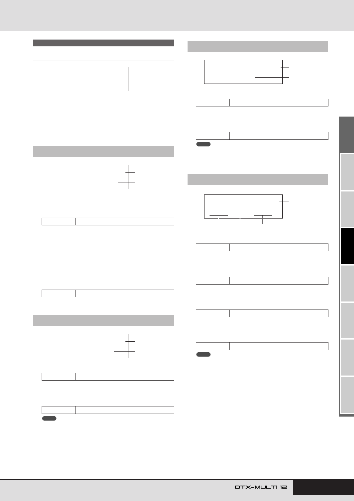
MIDI Setting Area (MIDI)
MIDI3-3≥≥≥≥≥Ch≥1
≥≥≥≥Pan=≥C
1
2
MIDI3-4≥≥≥≥≥Ch≥1
M000/L000/PC001
1
32 4
MIDI3 OTHER
Other MIDI Settings
MIDI3
≥≥≥≥≥OTHER
In the OTHER section, you can set various MIDI messages to be
sent whenever the current kit is selected. With the OTHER page
(MIDI3) displayed, press the [ENTER] button to access its eight
parameter-setting pages (MIDI3-1 through MIDI3-8). You can
use the [B]/[C] buttons to navigate between these pages.
MIDI3-1 Transmit page
MIDI3-1≥≥≥≥≥Ch≥1
≥≥Transmit=all
1 MIDI channel (Ch)
Use this parameter to select the MIDI channel (1 to 16) to be
set.
Settings 1 to 16
1
2
MIDI3-3 Pan page
1 MIDI channel (Ch)
Settings 1 to 16
B Transmit
Use this parameter to set the pan value to be sent whenever
the current kit is selected.
Settings L63 to C to R63
NOTE
• If “off” or “PC” has been selected on the Transmit page (MIDI3-1), this
setting will be displayed as “---” and modification will not be possible.
MIDI3-4 Program Change page
B Transmit
Use this parameter to indicate which MIDI messages are to be
sent whenever the current kit is selected.
•off ............. No MIDI messages will be sent.
• all ............. All applicable MIDI messages will be sent. (See
the following parameter-setting page descriptions for more details.)
•PC............. Only program change messages and bank-select
MSB/LSB messages will be sent.
Settings off, all, or PC
MIDI3-2 Volume page
MIDI3-2≥≥≥≥≥Ch≥1
≥≥≥Volume=100
1
2
1 MIDI channel (Ch)
Settings 1 to 16
B Transmit
Use this parameter to set a volume value to be sent whenever
the current kit is selected.
Settings 0 to 127
NOTE
• If “off” or “PC” has been selected on the Transmit page (MIDI3-1), this
setting will be displayed as “---” and modification will not be possible.
1 MIDI channel (Ch)
Settings 1 to 16
B Bank select MSB (M)
Use this parameter to set a bank-select MSB value to be sent
whenever the current kit is selected.
Settings 000 to 127
C Bank select LSB (L)
Use this parameter to set a bank-select LSB value to be sent
whenever the current kit is selected.
Settings 000 to 127
D Program change (PC)
Use this parameter to set a program-change number to be sent
whenever the current kit is selected.
Settings 001 to 128
NOTE
• If “off” has been selected on the Transmit page (MIDI3-1), these settings will be displayed as “---” and modification will not be possible.
TRIGGER ReferenceKITMIDI VOICEUTILITY WAVEPATTERN
Owner’s Manual 67
Page 68
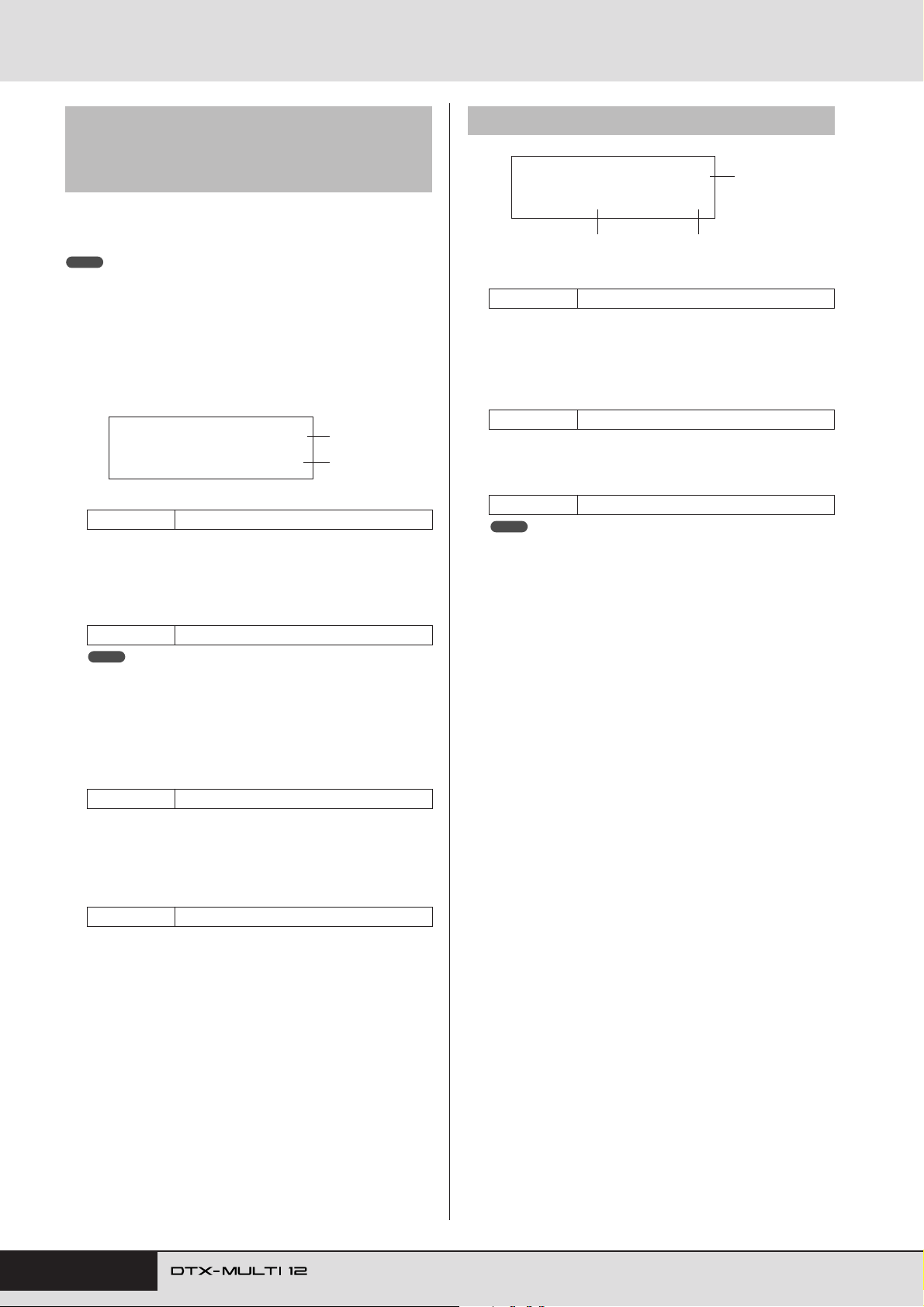
MIDI Setting Area (MIDI)
MIDI3-5 Variation Send Level page
MIDI3-6 Chorus Send Level page
MIDI3-7 Reverb Send Level page
On the Variation Send Level, Chorus Send Level, and Reverb
Send Level pages, you can adjust the send level to be set for each
of the corresponding effect units when the current kit is selected.
NOTE
• If “off” or “PC” has been selected on the Transmit page (MIDI3-1), theses
settings will be displayed as “---” and modification will not be possible.
Parameter 2 from each of the pages is used to adjust the corresponding send level. Parameter 1 is identical on all three pages.
[Setting example using the Variation Send Level
page (MIDI3-5)]
MIDI3-5≥≥≥≥≥Ch≥1
Var=≥≥0(Dry=127)
1
2
1 MIDI channel (Ch)
Settings 1 to 16
[MIDI3-5 Variation Send Level page]
B Variation send level (Var)
Use this parameter to set the variation-effect send level to be
sent whenever the current kit is selected.
Settings 0 to 127
NOTE
• If the MIDI channel 1 is set to 10, this setting will be displayed as “---”
and modification will not be possible.
MIDI3-8 CC Number & Value page
MIDI3-8≥≥≥≥≥Ch≥1
1
CCNo=off/Val=≥≥0
32
1 MIDI channel (Ch)
Settings 1 to 16
B Control change number (CCNo)
Use this parameter to set the type (or number) of MIDI Control Change message to be sent whenever the current kit is
selected. No control-change messages are sent when “off” is
set.
Settings off or 1 to 95
C Control change value (Val)
Use this parameter to set a value for the MIDI Control Change
messages to be sent whenever the current kit is selected.
Settings 0 to 127
NOTE
• If “off” or “PC” has been selected on the Transmit page (MIDI3-1),
these settings will be displayed as “---” and modification will not be
possible.
• If the type of MIDI Control Change message set on this page (MIDI3-8)
matches one of the control-change message types set on the following
pages, this page’s setting will have priority: Volume (MIDI3-2), Pan
(MIDI3-3), Variation Send Level (MIDI3-5), Chorus Send Level (MIDI3-
6), or Reverb Send Level (MIDI3-7).
[MIDI3-6 Chorus Send Level page]
2 Chorus send level (ChoSend)
Use this parameter to set the chorus send level to be sent
whenever the current kit is selected.
Settings 0 to 127
[MIDI3-7 Reverb Send Level page]
2 Reverb send level (RevSend)
Use this parameter to set the reverb send level to be sent
whenever the current kit is selected.
Settings 0 to 127
68 Owner’s Manual
Page 69
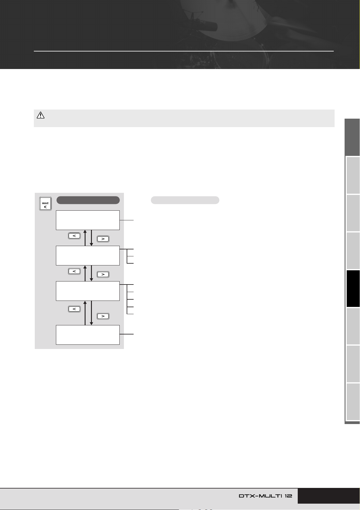
WAVE Setting Area (WAVE)
This section describes the WAVE setting area, which can be accessed using the [WAVE] button. Your DTX-MULTI 12
can be used to import AIF and WAV audio files from a wide range of sources. These files (referred to as “waves”) can
then be used in the same way as the instrument’s preset voices and patterns. The WAVE setting area is used to import
and edit waves.
CAUTION
• Be sure to store any imported waves or settings that you have edited before turning off the instrument or selecting a new wave. (See page 45.)
Makeup of WAVE Setting Area
The following four sections (WAVE1 to WAVE4) make up the WAVE setting area. Use the [B]/[C] buttons to navigate between these
sections. If a section contains parameter-setting pages, the [ENTER] button will light up. Press the [ENTER] button to access these pages.
In certain cases, a number of additional pages may be accessed from a parameter setting page, also using the lit [ENTER] button. Furthermore, you can press the [EXIT] button to move back towards the top of the setting area.
Sections
WAVE1
WV001:EmptyWave
WAVE2
≥≥≥≥≥COMMON
WAVE3
≥≥≥≥≥≥JOB
WAVE4
≥≥MEMORY≥INFO
Parameter-setting pages
Wave Selection & Playback............................................................................. Page 70
WAVE2-1 Wave Playback Mode page.............................................................Page 70
WAVE2-2 Trimming page ................................................................................Page 71
WAVE2-3 Wave Name page ...........................................................................Page 71
WAVE3-1 Import All page ............................................................................... Page 72
WAVE3-2 Normalize page............................................................................... Page 73
WAVE3-3 Delete page ....................................................................................Page 73
WAVE3-4 Delete All page ...............................................................................Page 73
WAVE3-5 Optimize Memory page................................................................... Page 73
WAVE4-1 Memory Info page........................................................................... Page 73
Owner’s Manual 69
TRIGGER ReferenceKITMIDI VOICEUTILITY WAVEPATTERN
Page 70
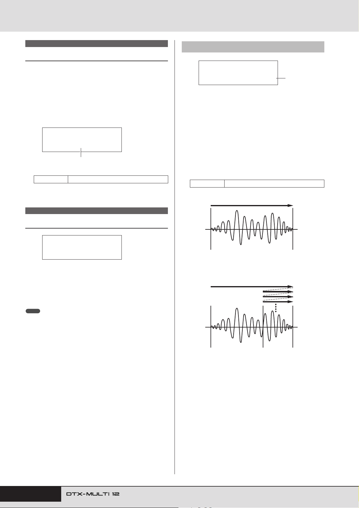
WAVE Setting Area (WAVE)
WAVE1
Wave Selection & Playback
You can use the Select Wave page (WAVE1) to select and play
waves. Only waves that have been saved in the DTX-MULTI 12’s
internal memory by importing (see page 72) will be available for
selection on this page. In other words, audio files stored on a USB
memory device are not immediately made available for selection
simply by plugging in the device.
On the Select Wave page, you can preview the currently selected
wave by pressing and holding the [WAVE] button. Release the
button to stop playback.
WAVE1
WV001:My≥Wave
1
A Wave number: Wave name
Settings WV001 to WV500
WAVE2
WAVE2-1 Wave Playback Mode page
WAVE2-1≥<COMMON>
PlayMode=oneshot
1 Playback mode (PlayMode)
Use this parameter to set the way in which the selected wave
will be played when assigned to a pad. For details on editing
start, end, and loop points, see the description of the Trimming page (WAVE2-2) below.
• oneshot ..... The wave will be played once only from the start
point to the end point. This mode is normally
selected for drums, special effects, and other
non-looped sounds.
• loop .......... The wave will be played continuously, first from
the start point to the end point, and then repeatedly from the loop point to the end point.
Settings oneshot or loop
One-shot playback
1
Playback Mode, Trim Points & Name
WAVE2
≥≥≥≥≥COMMON
In the COMMON section, you can choose a playback mode for
the currently selected wave and perform other related operations
such as trimming and naming. With the COMMON page
(WAVE2) displayed, press the [ENTER] button to access its three
parameter-setting pages (WAVE2-1 to WAVE2-3). You can use
the [B]/[C] buttons to navigate between these pages.
NOTE
• If the selected wave contains no data, the [ENTER] button will not open
parameter-setting pages.
Start point End point
Looped playback
Start point End point
Loop point
70 Owner’s Manual
Page 71
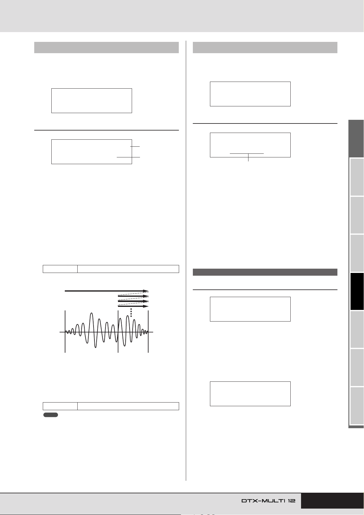
WAVE Setting Area (WAVE)
WAVE2-3≥<COMMON>
≥≥≥≥≥≥Name
WAVE2-3-1
≥≥[MyWave≥1≥]
Wave name
!"#$%&'()*+,-./0123456789:;<=>?@
ABCDEFGHIJKLMNOPQRSTUVWXYZ[\]^_`
abcdefghijklmnopqrstuvwxyz{|}ßå
WAVE3
≥≥≥≥≥≥JOB
≥≥≥Normalize
≥Are≥you≥sure?
WAVE2-2 Trimming page
From the Trimming page, you can edit the currently selected
wave’s start, end, and loop points. With the Trimming page
(WAVE2-2) displayed, press the [ENTER] button to open the
Trimming Settings page.
WAVE2-2≥<COMMON>
≥≥≥≥Trimming
WAVE2-2-1 Trimming Settings page
WAVE2-2-1≥≥start
≥≥Point=05000
1 Trim point
Use this parameter to select the trim point to be set. As shown
in the diagram below, three different types of trim point can
be selected – start, loop, and end.
• Start ........ This is the position at which playback will start.
In other words, no data in front of this point (i.e.,
with a smaller position value) will be played.
• Loop .......This is the position at which looping will start. If
“loop” has been selected on the Wave Playback
Mode page (WAVE2-1), playback will loop continuously between this point and the end point.
• End .........This is the position at which playback will end. In
other words, no data behind this point (i.e., with a
larger position value) will be played.
Settings start, loop, or end
1
2
WAVE2-3 Wave Name page
From the Wave Name page, you can assign a name to the currently selected wave. With this page displayed, press the
[ENTER] button to open the Wave Name Setting page.
WAVE2-3-1 Wave Name Setting page
On the Wave Name Setting page, you can set a wave name of
up to 10 characters in length. Use the [B]/[C] buttons to
move the flashing cursor to the character you want to change,
and then select a new character using the [-/DEC] and [+/
INC] buttons. The following characters can be used in wave
names.
[space]
WAVE3 JOB
Looped playback
Start point End point
Loop point
B Point
Use this parameter to specify a five-digit position value for
the selected trim point. The [B]/[C] buttons can be used to
move the cursor between digits, and the [-/DEC] and [+/INC]
buttons can be used to change the corresponding value.
Settings From 00000
NOTE
•To audition your wave with the current settings, press the [WAVE] but-
ton with the Trimming Settings page displayed.
Other Wave-Related Tasks
In the JOB section, you can create waves by importing WAV or
AIFF files from a USB memory device into the DTX-MULTI 12’s
internal memory, and you can also perform a number of other
related tasks. With the JOB page (WAVE3) displayed, press the
[ENTER] button to access its five parameter-setting pages
(WAVE3-1 to WAVE3-5). You can use the [B]/[C] buttons to
navigate between these pages.
Whenever you press the [ENTER] button to perform an operation
on a JOB section page, you will be asked to reconfirm that you
want to do so. Press the [ENTER] button once again to proceed.
TRIGGER ReferenceKITMIDI VOICEUTILITY WAVEPATTERN
Owner’s Manual 71
Page 72
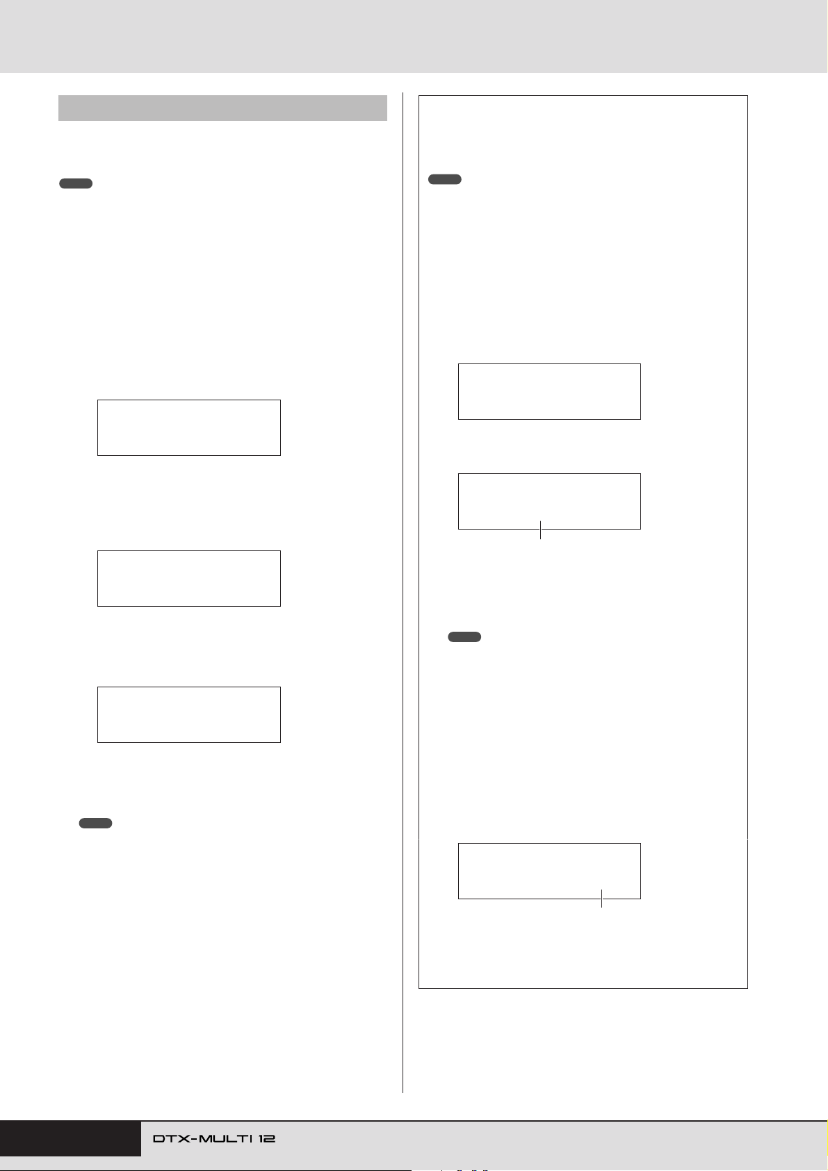
WAVE Setting Area (WAVE)
WAVE3-1 Import All page
Using the Import All page, you can import all WAV or AIFF files
from a USB memory device into your DTX-MULTI 12’s internal
memory.
NOTE
• Files can also be imported individually, and the procedure for doing so is
described on the right.
• Only WAV and AIFF audio files can be imported.
Ensure that the WAV or AIFF files to be imported are
1
located in the USB memory device’s root directory,
using a computer to move them if necessary.
Plug the USB memory device into the instrument’s
2
USB TO DEVICE port.
With the JOB page (WAVE3) displayed, press the
3
[ENTER] button, and if necessary, the [B]/[C] but-
tons to open the Import All page (WAVE3-1).
WAVE3-1≥≥≥≥<JOB>
≥≥≥Import≥All
Press the [ENTER] button once again.
4
You will be asked to confirm that you want to import all files.
You can press the [EXIT] button to return to the previous page
without importing.
Importing Individual Audio Files
The following describes how to import individual WAV or
AIFF files from a USB memory device into the DTX-MULTI
12’s internal memory.
NOTE
• Only WAV and AIFF audio files can be imported.
Ensure that the WAV or AIFF file to be imported is
1
located in the USB memory device’s root directory, using a computer to move it if necessary.
Plug the USB memory device into the instru-
2
ment’s USB TO DEVICE port.
Hold down the [SHIFT] button and press the
3
[WAVE] button to open the IMPORT page shown
below.
IMPORT
≥≥≥Surdo.WAV
Use the [-/DEC] and [+/INC] buttons to select the
4
audio file you want to import.
IMPORT
≥≥≥FillX.AIF
Name of audio file to be imported
≥≥≥Import≥All
≥Are≥you≥sure?
Press the [ENTER] button to import.
5
Each imported wave will be automatically assigned a wave
number.
Now≥Importing...
[EXIT]≥to≥cancel
You can press the [EXIT] button at any time during the import
process to terminate it. Files that have been fully imported at
that time will be retained in the DTX-MULTI 12’s internal
memory.
NOTE
• If there is insufficient free space in the instrument’s internal memory,
the message “Wave memory full.” will be displayed and the import process will be terminated. Before repeating the import process, make
additional memory available by deleting unneeded waves on the
Delete page (WAVE3-3) or the Delete All page (WAVE3-4).
Press the [ENTER] button to import.
5
When the selected file has been imported, the IMPORT
page will allow you to assign it to a pad within the currently selected kit.
NOTE
• If there is insufficient free space in the instrument’s internal memory, the message “Wave memory full.” will be displayed and the
import process will be terminated. Before repeating the import process, make additional memory available by deleting unneeded
waves on the Delete page (WAVE3-3) or the Delete All page
(WAVE3-4).
Use the [-/DEC] and [+/INC] buttons to select the
6
pad to which the wave is to be assigned.
The available options are 01 to 13, 13R1, 13R2, 14 to 17,
FTSW, HHCL, and HHSP. You can also select a pad by
striking it. Alternatively, you can select “off” to store the
imported wave in the instrument’s internal memory without assigning it to a pad at this time.
IMPORT
≥PadAssign=¡£Ω¡
Pad number
When you have assigned the wave as required,
7
press the [ENTER] button to complete the procedure.
72 Owner’s Manual
Page 73
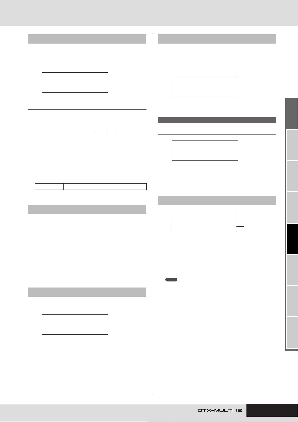
WAVE Setting Area (WAVE)
WAVE3-5≥≥≥≥<JOB>
Optimize≥Memory
WAVE4
≥≥MEMORY≥INFO
WAVE4-1≥≥≥≥≥0.0%
≥≥0.4MB≥/≥64.0MB
1
2
WAVE3-2 Normalize page
From the Normalize page, you can increase the volume of the currently selected wave. With this page displayed, press the
[ENTER] button to open the Ratio page (WAVE3-2-1). Here you
can specify how much the volume of the wave is to be increased.
WAVE3-2≥≥≥≥<JOB>
≥≥≥Normalize
WAVE3-2-1 Ratio page
WAVE3-2-1
≥≥≥Ratio=100%
1 Ratio
Use this parameter to specify how much the wave’s volume is
to be increased. Generally, a ratio of 100% or lower is used.
With a setting of 100%, the volume will be increased to the
maximum possible level without clipping. (Ratios greater
than 100% can be specified; however, the wave may become
distorted as a result.)
Settings 1 to 800
1
WAVE3-5
From the Optimize Memory page, you can maximize the amount
of unused wave memory. In order to do this, the content of the
DTX-MULTI 12’s internal wave memory is rearranged to make
more memory available. Optimization can be an effective way to
increase the amount of memory available for waves.
Optimize Memory page
WAVE4 MEMORY INFO
Wave Memory Status
The MEMORY INFO section allows you to display the current
usage status of the DTX-MULTI 12’s wave memory. To view the
memory-usage status, navigate to the MEMORY INFO section
(WAVE4) and press the [ENTER] button.
WAVE3-3 Delete page
From the Delete page, you can delete the wave currently selected
on the Select Wave page (WAVE1).
WAVE3-3≥≥≥≥<JOB>
≥≥≥≥≥Delete
Press the [ENTER] button with the Delete page displayed, and
when asked to confirm that you wish to proceed, press the
[ENTER] button once again.
WAVE3-4 Delete All page
From the Delete All page, you can delete all waves from the
DTX-MULTI 12’s internal wave memory.
WAVE3-4≥≥≥≥<JOB>
≥≥≥Delete≥All
Press the [ENTER] button with the Delete All page displayed, and
when asked to confirm that you wish to proceed, press the
[ENTER] button once again.
WAVE4-1 Memory Info page
1 Memory usage ratio (%)
This indicates how much of the total wave memory is currently being used in percentage format.
B Used memory / Total memory
This indicates separately the amount of wave memory used
and the total wave memory in megabyte (MB) units.
NOTE
• Certain types of audio file may require more of the instrument’s memory than indicated by the corresponding file size shown on your computer.
TRIGGER ReferenceKITMIDI VOICEUTILITY WAVEPATTERN
Owner’s Manual 73
Page 74
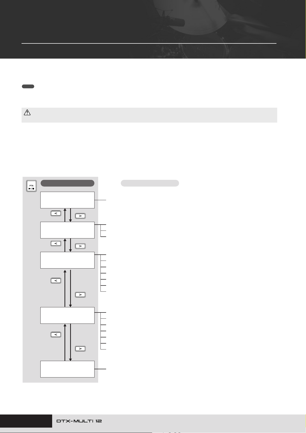
PATTERN Setting Area (PTN)
This section describes the PATTERN setting area, which can be accessed using the [PTN] button. Built into the DTXMULTI 12 are a range of Preset patterns specially for playback (P001 to P128) in addition to User patterns that can be
freely recorded and edited (U001 to U050). Use the PATTERN area to record and edit these patterns.
NOTE
•Parameter setting pages from the COMMON section (PTN2), the MIDI section (PTN3), and the JOB section (PTN4) will not be accessible when a Preset pattern
has been selected. You can, however, edit a Preset pattern by first selecting an empty User pattern and then copying the Preset pattern into it using the Copy
Pattern page (PTN4-5).
CAUTION
• Be sure to store any recorded patterns or settings that you have edited before turning off the instrument or selecting a new pattern. (See page 45.)
Makeup of PATTERN Setting Area
The PATTERN setting area is subdivided into five different sections (PTN1 to PTN5). Use the [B]/[C] buttons to navigate between
these sections. If a section contains parameter-setting pages, the [ENTER] button will light up. Press the [ENTER] button to access these
pages. In certain cases, a number of additional pages may be accessed from a parameter setting page, also using the lit [ENTER] button.
Furthermore, you can press the [EXIT] button to move back towards the top of the setting area.
Sections
PTN1≥≥≥ƒ=120≥4/4
©P001:Demo≥01
PTN2≥≥≥≥≥≥≥≥≥≥≥≥
≥≥≥≥≥COMMON≥≥≥≥≥
PTN3
≥≥≥≥≥≥MIDI
PTN4
≥≥≥≥≥≥JOB
Parameter-setting pages
Select Pattern.................................................................................................. Page 75
PTN2-1 Pattern Loop page ............................................................................. Page 75
PTN2-2 Pattern Tempo page........................................................................... Page 75
PTN2-3 Pattern Name page............................................................................ Page 76
PTN3-1 MIDI Transmit page............................................................................ Page 76
PTN3-2 MIDI Volume page ............................................................................. Page 77
PTN3-3 MIDI Pan page................................................................................... Page 77
PTN3-4 Bank Select page............................................................................... Page 77
PTN3-5 Variation Send page .......................................................................... Page 77
PTN3-6 Chorus Send page............................................................................. Page 78
PTN3-7 Reverb Send page............................................................................. Page 78
PTN4-1 Quantize Pattern page....................................................................... Page 78
PTN4-2 Merge Pattern page ........................................................................... Page 79
PTN4-3 Clear Pattern page............................................................................. Page 79
PTN4-4 Clear All Patterns page...................................................................... Page 79
PTN4-5 Copy Pattern page............................................................................. Page 79
PTN4-6 Exchange Patterns page ...................................................................Page 80
PTN4-7 Import SMF page ............................................................................... Page 80
74 Owner’s Manual
PTN5
≥≥MEMORY≥INFO
PTN5-1 Memory Info page.............................................................................. Page 81
Page 75
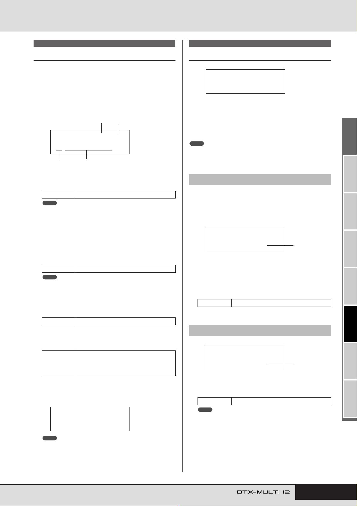
PATTERN Setting Area (PTN)
PTN2
≥≥≥≥≥COMMON
PTN2-1≥≥<COMMON>
≥≥≥≥Loop=off
1
PTN2-2≥≥<COMMON>
≥≥≥Tempo=120
1
PTN1
Select Pattern
On the Select Pattern page (PTN1), you can select and play patterns and also set their tempo and time signature. To access this
page, press the [PTN] button, and if necessary, the [B]/[C] but-
tons. If you again press the [PTN] button with this page displayed,
the selected pattern will start to play. To stop playback, press the
[PTN] button once again with the Select Pattern page (PTN1) displayed. Whenever you want to edit or record a pattern, furthermore, be sure to select it first on this page.
1
2
PTN1≥≥≥ƒ=120≥4/4
©P001:Demo≥01
3
1 Tempo
Use this parameter to set the tempo at which the selected pattern will be played.
Settings 30 to 300
NOTE
• Whenever you select a new pattern, its tempo will be set automatically.
• The Tempo parameter’s setting will be displayed as “ext” and modification will not be possible if “ext” has been selected on the UTILITY
area’s MIDI Sync page (UTIL6-6) or if “auto” has been selected on that
page and MIDI clock messages are being received from an external
device.
4
PTN2 COMMON
Looping, Tempo & Pattern Names
In the COMMON section, you can specify whether the currently
selected pattern is to be played repeatedly as a loop, and you can
also set its tempo and name. With the COMMON page (PTN2)
displayed, press the [ENTER] button to access its three parame-
ter-setting pages (PTN2-1 to PTN2-3). You can use the [B]/[C]
buttons to navigate between these pages.
NOTE
• This section can be used only with User patterns. If a Preset pattern has
been selected, the [ENTER] button will not open a parameter-setting page.
PTN2-1 Pattern Loop page
Using the Pattern Loop page, you can specify whether or not the
selected pattern is to be played repeatedly as a loop. The selection
made on this page will apply regardless of whether the pattern is
played using the [
has been assigned.
A] button or by striking a pad to which it
B Time signature
Use this parameter to set the time signature for playback of
the selected pattern.
Settings 1/4 to 16/4, 1/8 to 16/8, or 1/16 to 16/16
NOTE
• Whenever you select a new pattern, its time signature will be set automatically.
C Pattern category
Use this parameter to select either the Preset (P) or User
(
U) pattern category.
Settings P or U
D Pattern number: Pattern name
Use these parameters to select the pattern to be played,
recorded, or processed.
With “P” (Preset pattern) selected: 001 to
Settings
128
With “U” (User pattern) selected: 001 to
050
Whenever a demo pattern (P001 to P003) is being played, a
page similar to that shown below will be displayed and modification of the tempo or time signature will not be possible.
≥<<Demo≥01>>
P001:PercsMaster
1 Loop
If “on” is selected for this parameter, playback of the pattern
will start again from the beginning whenever it finishes (i.e.,
looped playback). When set to “off”, the pattern will be
played once to the end and will then stop (i.e., one-shot playback).
Settings off or on
PTN2-2 Pattern Tempo page
1 Tempo
Use this parameter to set a tempo for playback of the selected
pattern.
Settings 30 to 300
NOTE
• If the pattern is assigned to a kit, the kit’s tempo setting (see page 47)
will take priority over this setting.
TRIGGER ReferenceKITMIDI VOICEUTILITY WAVEPATTERN
NOTE
• Playback of the click track or of patterns assigned to pads will be
stopped whenever playback of a demo pattern is star ted.
• Playback of demo patterns can be stopped by pressing any button
other than [SHIFT].
Owner’s Manual 75
Page 76
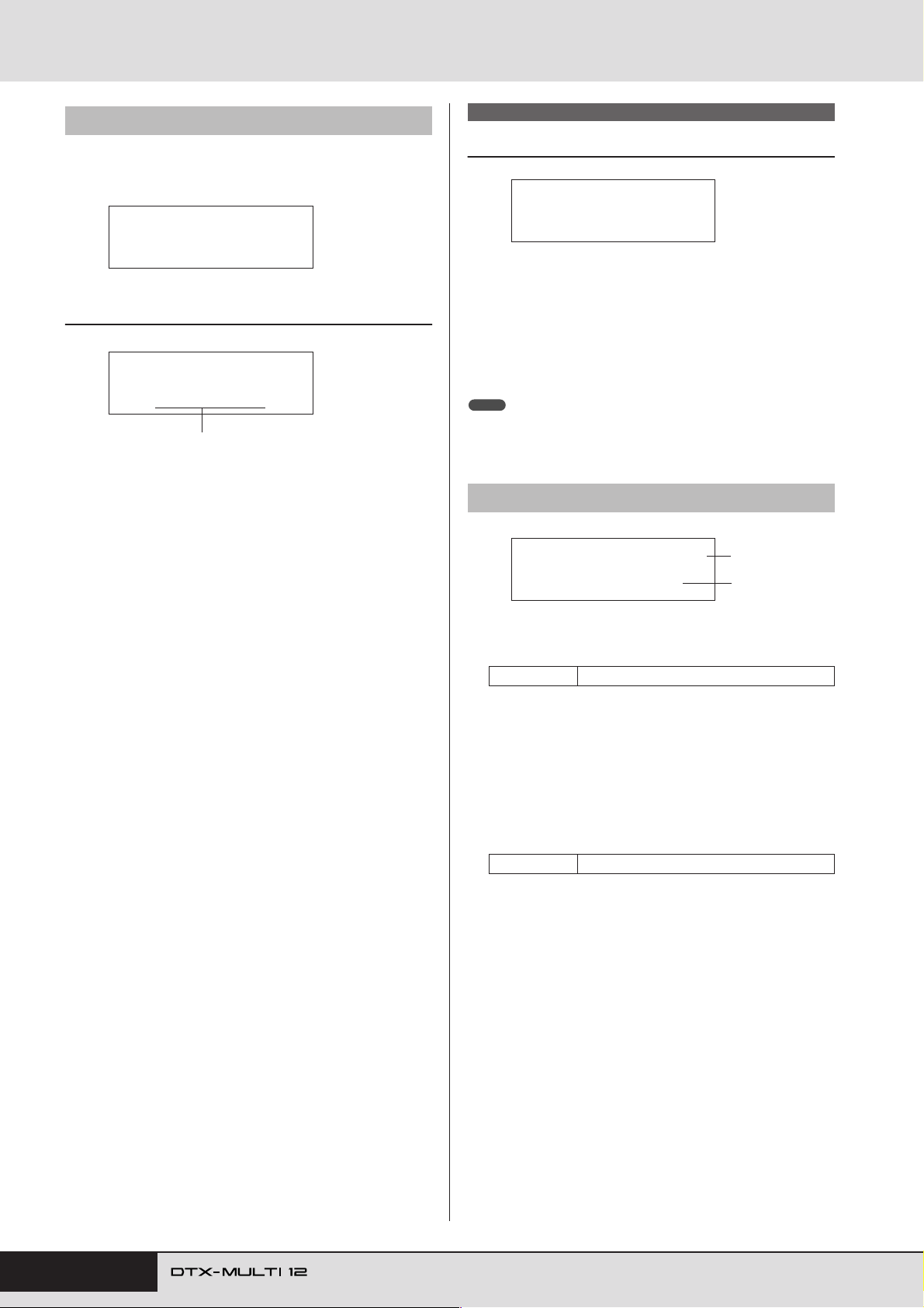
PATTERN Setting Area (PTN)
PTN2-3 Pattern Name page
With the Pattern Name page displayed, press the [ENTER] button
to edit the name of the currently selected pattern.
PTN2-3≥≥<COMMON>
≥≥≥≥≥≥Name
PTN2-3-1 Pattern Name Setting page
PTN2-3-1
≥≥[Pattern≥1≥]≥≥
Pattern name
In the Pattern Name Setting page (PTN2-3-1), you can freely
specify a pattern name of up to ten characters in length. Use
the [
B
]/[C] buttons to move the flashing cursor to the char-
acter you want to change, and then select a character using the
[-/DEC] and [+/INC] buttons. The following characters can be
used in pattern names.
[space]
!"#$%&'()*+,-./0123456789:;<=>?@
ABCDEFGHIJKLMNOPQRSTUVWXYZ[\]^_`
abcdefghijklmnopqrstuvwxyz{|}ßå
PTN3 MIDI
MIDI Settings for Patterns
PTN3
≥≥≥≥≥≥MIDI
In the MIDI section, you can configure the MIDI messages sent
by the currently selected pattern on each individual MIDI channel. These settings affect MIDI messages sent to both the DTXMULTI 12’s internal tone generator and external MIDI devices.
With the MIDI page (PTN3) displayed, press the [ENTER] button
to access its seven parameter-setting pages (PTN3-1 to PTN3-7).
You can use the [
pages.
NOTE
• This section can be used only with User patterns. If a Preset pattern has
been selected, the [ENTER] button will not open a parameter-setting page.
PTN3-1 MIDI Transmit page
1 MIDI channel (Ch)
Use this parameter to select the MIDI channel (1 to 16) to be
set.
Settings 1 to 16
B
]/[
C
] buttons to navigate between these
PTN3-1≥≥≥≥≥≥Ch≥1
≥≥Transmit=all
1
2
B Transmit
Use this parameter to specify which MIDI messages will be
sent to the internal tone generator and to external MIDI
devices by the currently selected pattern on the MIDI channel
indicated by 1.
•off ............. No MIDI messages will be sent.
• all.............. All applicable MIDI messages will be sent.
•PC............. Only MIDI Program Change messages (includ-
ing bank-select MSB/LSB) will be sent.
Settings off, all, or PC
76 Owner’s Manual
Page 77
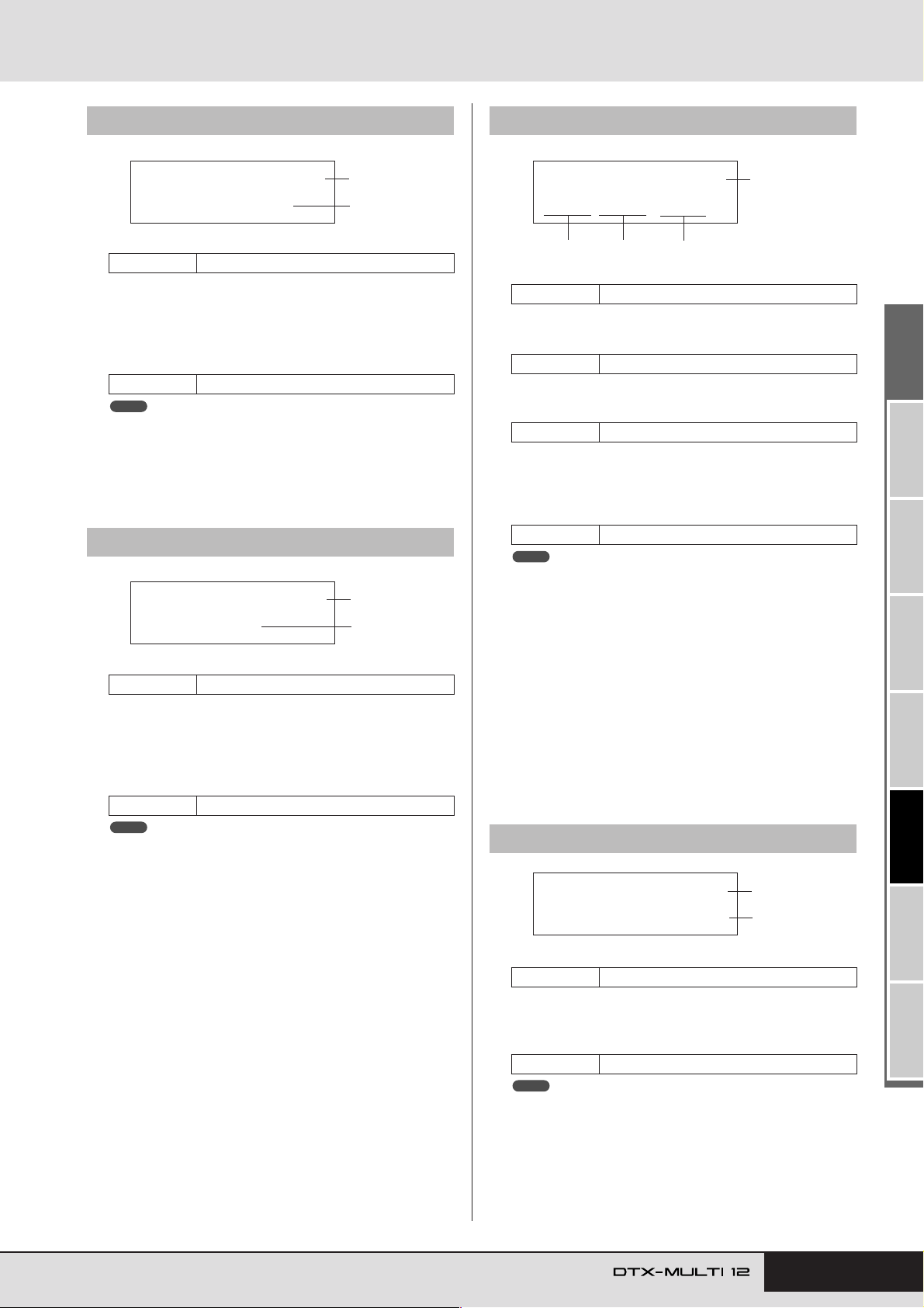
PATTERN Setting Area (PTN)
PTN3-4≥≥≥≥≥≥Ch≥1
M000/L000/PC001
1
2
4
3
PTN3-5≥≥≥≥≥≥Ch≥1
Var=≥≥0(Dry=127)
1
2
PTN3-2 MIDI Volume page
PTN3-2≥≥≥≥≥≥Ch≥1
≥≥≥Volume=100
1
2
1 MIDI channel (Ch)
Settings 1 to 16
B Volume
Use this parameter to set the MIDI volume (Control Change
7) sent by the currently selected pattern on the MIDI channel
indicated by 1. In terms of the internal tone generator, this
value affects all voices played on that channel.
Settings 0 to 127
NOTE
• If “off” or “PC” has been selected on the MIDI Transmit page (PTN3-1),
this setting will be displayed as “---” and modification will not be possible.
• If you change the volume setting for MIDI channel 10, the setting on
the Kit Volume page (KIT2-1) will also change to this new setting.
PTN3-3 MIDI Pan page
PTN3-3≥≥≥≥≥≥Ch≥1
≥≥≥≥Pan=≥C
1
2
1 MIDI channel (Ch)
Settings 1 to 16
B Pan
Use this parameter to set the stereo panning (Control Change
10) sent by the currently selected pattern on the MIDI channel
indicated by 1. In terms of the internal tone generator, this
value affects all voices played on that channel.
Settings L64 to C to R63
NOTE
• If “off” or “PC” has been selected on the MIDI Transmit page (PTN3-1),
this setting will be displayed as “---” and modification will not be possible.
PTN3-4 Bank Select page
1 MIDI channel (Ch)
Settings 1 to 16
B Bank select MSB (M)
Use this parameter to set a bank-select MSB value.
Settings 000 to 127
C Bank select LSB (L)
Use this parameter to set a bank-select LSB value.
Settings 000 to 127
D Program change (PC)
Use this parameter to set a program-change number sent by
the currently selected pattern on the MIDI channel indicated
by 1.
Settings 001 to 128
NOTE
• If “off” has been selected on the MIDI Transmit page (PTN3-1), this
setting will be displayed as “---” and modification will not be possible.
To select a DTX-MULTI 12 drum kit, set parameters for
MIDI channel 10 as follows.
• Preset kits:
MSB = 125, LSB = 000, PC = Preset kit number
• User kits between U001 and U100:
MSB = 125, LSB = 001, PC = 001 to 100
•User kits between U101 and U200:
MSB = 125, LSB = 002, PC = 001 to 100
If a program-change setting is made for MIDI channel 10, the
current drum kit will be changed immediately.
PTN3-5 Variation Send page
1 MIDI channel (Ch)
Settings 1 to 16
B Variation send level (Var)
Use this parameter to set the variation-send level to be sent by
the currently selected pattern.
Settings 0 to 127
NOTE
• If “off” or “PC” has been selected on the MIDI Transmit page (PTN3-1),
this setting will be displayed as “---” and modification will not be possible.
• If MIDI channel 10 is selected, this setting will be displayed as “---” and
modification will not be possible.
Owner’s Manual 77
TRIGGER ReferenceKITMIDI VOICEUTILITY WAVEPATTERN
Page 78
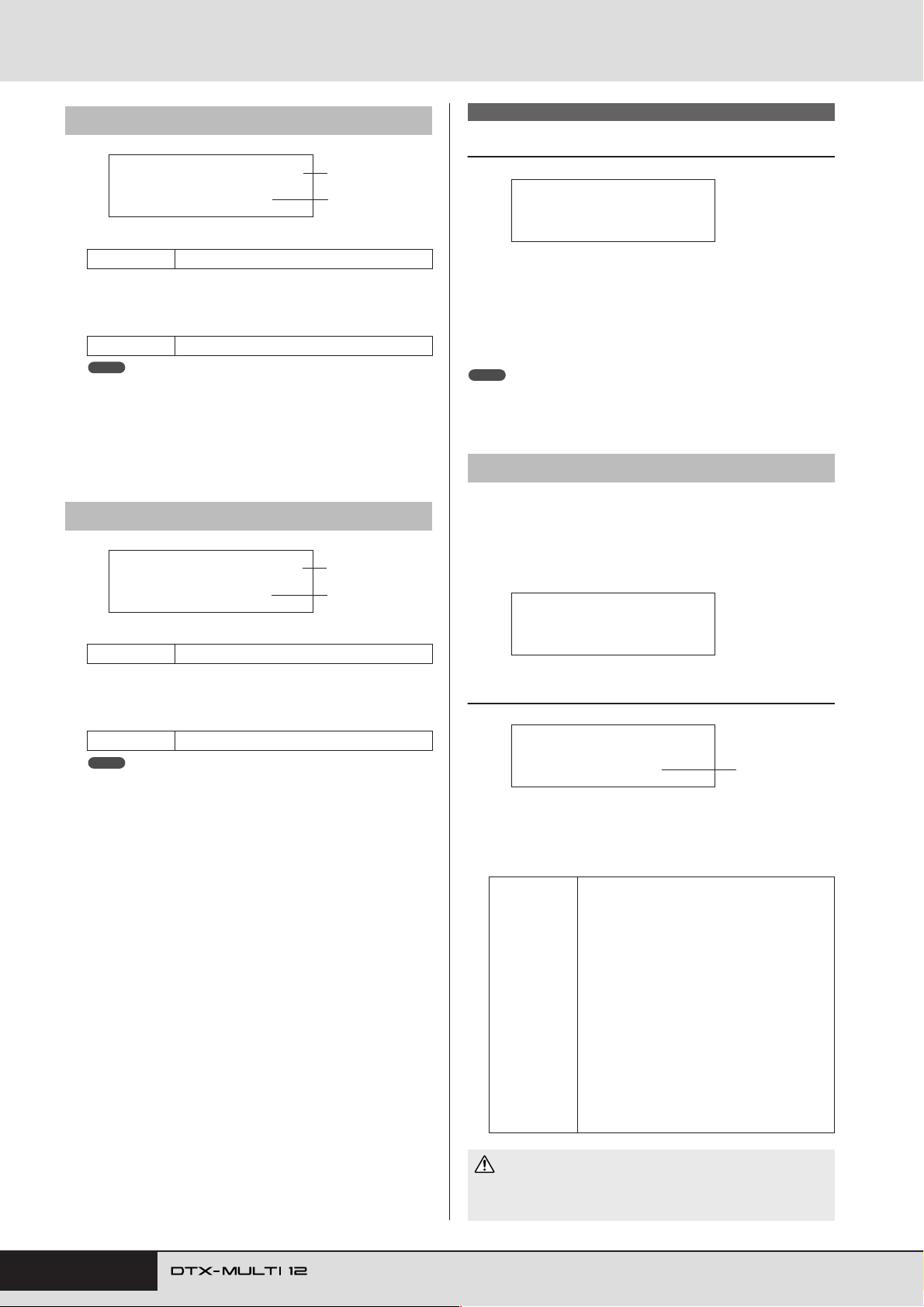
PATTERN Setting Area (PTN)
PTN3-6 Chorus Send page
PTN3-6≥≥≥≥≥≥Ch≥1
≥≥ChoSend=≥≥0
1
2
1 MIDI channel (Ch)
Settings 1 to 16
B Chorus send level (ChoSend)
Use this parameter to set the chorus-send level to be sent by
the currently selected pattern.
Settings 0 to 127
NOTE
• If “off” or “PC” has been selected on the MIDI Transmit page (PTN3-1),
this setting will be displayed as “---” and modification will not be possible.
• If you change the chorus send level for MIDI channel 10, the setting on
the Chorus Send page (KIT3-1) for the currently selected kit will also
change to this new setting.
PTN3-7 Reverb Send page
PTN3-7≥≥≥≥≥≥Ch≥1
≥≥RevSend=≥40
1
2
1 MIDI channel (Ch)
Settings 1 to 16
PTN4 JOB
Pattern Quantization & Management
PTN4
≥≥≥≥≥≥JOB
In the JOB section, you can quantize the currently selected User
pattern, import SMF files, and perform other related tasks. With
the JOB page (PTN4) displayed, press the [ENTER] button to
access its seven parameter-setting pages (PTN4-1 to PTN4-7).
You can use the [
pages.
NOTE
• This section can be used only with User patterns. If a Preset pattern has
been selected, the [ENTER] button will not open a parameter-setting page.
PTN4-1 Quantize Pattern page
From the Quantize Pattern page, you can correct irregularities in
the timing of notes making up the currently selected User pattern.
This is referred to as quantizing. With the Quantize page displayed, press the [ENTER] button to open the Quantize Pattern
Setting page.
B
]/[C] buttons to navigate between these
PTN4-1≥≥≥≥≥<JOB>
≥≥≥≥Quantize
B Reverb send level (RevSend)
Use this parameter to set the reverb-send level to be sent by
the currently selected pattern.
Settings 0 to 127
NOTE
• If “off” or “PC” has been selected on the MIDI Transmit page (PTN3-1),
this setting will be displayed as “---” and modification will not be possible.
• If you change the reverb send level for MIDI channel 10, the setting on
the Reverb Send page (KIT3-2) for the currently selected kit will also
change to this new setting.
PTN4-1-1 Quantize Pattern Setting page
PTN4-1-1
≥≥Quantize=ƒ
1 Quantize
Use this parameter to specify the quantizing resolution as a
division of a whole note. The lower the resolution, the finer
the correction of timing.
When time signature from PTN1 or for
Settings
recording is 3/8, 6/8, 9/8, 12/8, or 15/8:
˙3
˙
©3
©
ƒ
¨
When time signature from PTN1 is other
than the above:
˙3
˙
©3
©
ƒ3
ƒ
th
16 note triplets
th
16 notes
th
8 note triplets
th
8 notes
th
4 notes
Dotted 4 notes
th
16 note triplets
th
16 notes
th
8 note triplets
th
8 notes
th
4 note triplets
th
4 notes
1
th
78 Owner’s Manual
CAUTION
• The natural groove of a recorded performance may be lost as a
result of quantization. Note that once a pattern is quantized, it will
not be possible to reverse the procedure.
Page 79
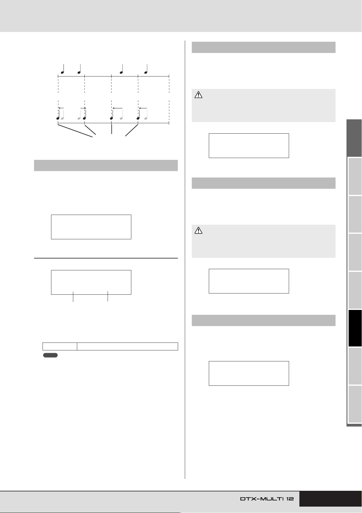
PATTERN Setting Area (PTN)
PTN4-3≥≥≥≥≥<JOB>
≥≥≥≥≥Clear
PTN4-4≥≥≥≥≥<JOB>
≥≥≥Clear≥All
PTN4-5≥≥≥≥≥<JOB>
≥≥≥≥≥≥Copy
Example of how quantizing works
These recorded notes were not played exactly in time.
Notes moved closer to the correct position through quantizing.
Exact position
PTN4-2 Merge Pattern page
From the Merge Pattern page, you can merge two patterns and
store the result as a User pattern. To start, select a User pattern to
hold the merged pattern on the Select Pattern page (PTN1). Then,
navigate to the Merge Pattern page and press the [ENTER] button
to open the Merge Pattern Settings page.
PTN4-2≥≥≥≥≥<JOB>
≥≥≥≥≥Merge
PTN4-2-1 Merge Pattern Settings page
PTN4-3 Clear Pattern page
From the Clear Pattern page, you can delete all data from the currently selected User pattern. To do so, press the [ENTER] button
with the Clear Pattern page displayed, and when asked to confirm
that you wish to proceed, press the [ENTER] button once again.
CAUTION
• When a User pattern is cleared as described above, its data is completely erased from the instrument’s pattern memory. Be sure, therefore, to always save important data on a USB memory device or the
like before deleting.
PTN4-4 Clear All Patterns page
From the Clear All Patterns page, you can delete data from all
User patterns. To do so, press the [ENTER] button with the Clear
All Patterns page displayed, and when asked to confirm that you
wish to proceed, press the [ENTER] button once again.
CAUTION
• When User patterns are cleared as described above, their data is
completely erased from the instrument’s pattern memory. Be sure,
therefore, to always save important data on a USB memory device
or the like before deleting.
PTN4-2-1≥<Merge>
≥©P004≥+≥©P005
1
1 Merge pattern 1
B Merge pattern 2
Use the above two parameters to specify the patterns that are
to be merged as one.
Settings P004 to P128 or U001 to U050
NOTE
• If the User pattern selected before opening the Merge Pattern page
already contains data, it will be overwritten with the merged pattern.
• The tempo and time signature of Merge pattern 1 are set as the tempo
and time signature of the merged pattern. If Merge pattern 1 is empty,
however, the tempo and time signature of Merge pattern 2 are used.
• The channel-specific MIDI settings of Merge pattern 1 are set as those
of the merged pattern. In the case, however, of MIDI channels for
which Merge pattern 1 contains no settings, any applicable settings
from Merge pattern 2 will be applied.
• Generally speaking, only patterns with similar tempos, time signatures,
and MIDI voice settings should be merged.
• Demo patterns cannot be selected for merging.
2
PTN4-5 Copy Pattern page
From the Copy Pattern page, you can copy a pattern to the currently selected User pattern. With the Copy Pattern page displayed, press the [ENTER] button to open the Copy Pattern
Setting page.
TRIGGER ReferenceKITMIDI VOICEUTILITY WAVEPATTERN
Owner’s Manual 79
Page 80
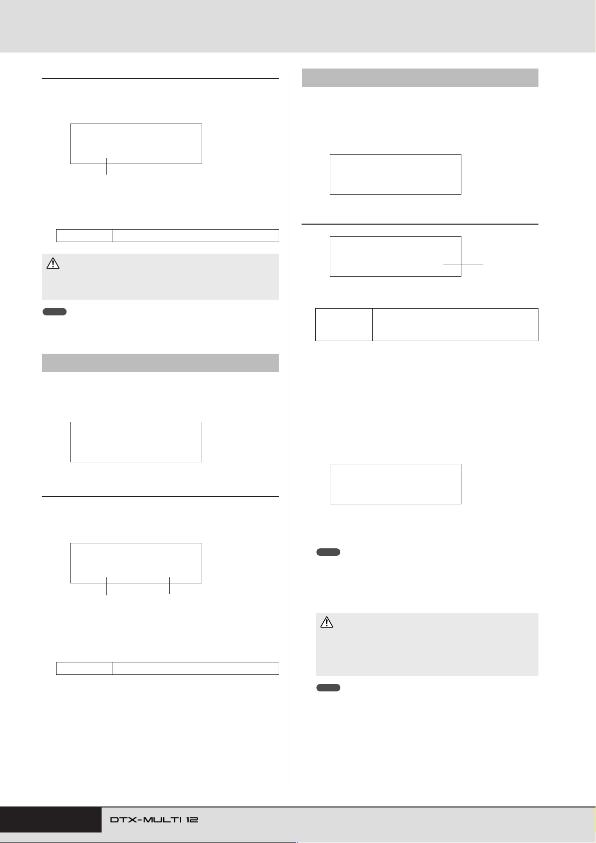
PATTERN Setting Area (PTN)
PTN4-5-1 Copy Pattern Setting page
With the Copy Pattern Setting page displayed, press the [ENTER]
button, and when asked to confirm that you wish to proceed, press
the [ENTER] button once again.
PTN4-5-1≥≥<Copy>
≥©P004≥-ßCurrent
1
1 Pattern to be copied
Use this parameter to select the pattern to be copied to the
currently selected User pattern.
Settings P004 to P128 or U001 to U050
CAUTION
• The currently selected User pattern is overwritten as a result of this
procedure. Be sure, therefore, to always save important data on a
USB memory device or the like before copying patterns.
NOTE
• Demo patterns cannot be copied.
PTN4-6 Exchange Patterns page
From the Exchange Patterns page, you can swap a pair of User
patterns. With the Exchange Patterns page displayed, press the
[ENTER] button to open the Exchange Patterns Settings page.
PTN4-6≥≥≥≥≥<JOB>
≥≥≥≥Exchange
PTN4-7 Import SMF page
From the Import SMF page, you can import a standard MIDI file
(SMF) into the DTX-MULTI 12 from a USB memory device for
use as a User pattern. SMFs contain sequenced MIDI data and
have a “.mid” file extension. It should be noted that the DTXMULTI 12 supports Format 0 SMFs only.
PTN4-7≥≥≥≥≥<JOB>
≥≥≥Import≥SMF
PTN4-7-1 Import SMF Setting page
PTN4-7-1<Import>
≥≥pattern1.mid
1 SMF file name
Use this parameter to select the SMF to be imported.
Any SMF file having extension .mid and
Settings
Plug a USB memory device containing the Format-0
1
SMF to be imported into the USB TO DEVICE port on
the side panel of the DTX-MULTI 12.
Navigate to the Import SMF page (PTN4-7) and press
2
the [ENTER] button to open the Import SMF Setting
page (PTN4-7-1) shown above. Select the SMF to be
imported and then press the [ENTER] button once
again.
You will be asked to confirm that you wish to proceed.
stored in the USB memory device’s root
directory.
1
PTN4-6-1 Exchange Patterns Settings page
With the Exchange Patterns Settings page displayed, press the
[ENTER] button, and when asked to confirm that you wish to proceed, press the [ENTER] button once again.
PTN4-6-1≥<Exchg>
≥©U001≥åß≥©U002
1
1 Exchange pattern 1
B Exchange pattern 2
Use these parameters to select the two User patterns to be
swapped.
Settings U001 to U050
2
≥≥≥Import≥SMF≥≥
≥Are≥you≥sure?
To import the selected SMF, press the [ENTER] but-
3
ton. Alternatively, press the [EXIT] button to return
to the previous page without importing.
NOTE
• If the currently selected User pattern already contains pattern data, it
will be overwritten with the imported data.
The message “Now importing...” will be displayed during the
import process.
CAUTION
• Do not unplug the USB memory device from the USB TO
DEVICE port or turn off either the USB memory device or the
DTX-MULTI 12 while data is being imported. Failure to observe
this precaution can lead to the USB memory device or the DTXMULTI 12 being permanently damaged.
NOTE
• Only standard MIDI files of Format 0 can be imported.
•In cer tain cases where a User pattern created from an impor ted SMF is
looped, voices may not change as expected when playback jumps from
the end back to the beginning, and instead, the voices settings from the
end of the pattern will be maintained throughout. Specifically, this happens when program change data from the SMF’s header is not read
upon return to the start of the pattern. To prevent this type of unintended
situation, move any program change messages slightly back from the
SMF header to ensure that they will be correctly read.
80 Owner’s Manual
Page 81
PTN5 MEMORY INFO
Pattern Memory Status
PTN5
≥≥MEMORY≥INFO
The MEMORY INFO section allows you to check the usage status of DTX-MULTI 12 memory for User patterns. To do so, navigate to this section (PTN5) and press the [ENTER] button.
PTN5-1 Memory Info page
PATTERN Setting Area (PTN)
PTN5-1≥≥≥≥≥≥0.0%
≥≥≥0.4KB/896.0KB
1
2
1 Memory usage ratio (%)
This indicates how much of the total User-pattern memory is
currently being used in percentage format.
B Used memory / Total memory (KB)
This indicates separately the amount of memory used and the
total memory in kilobyte (KB) units.
Owner’s Manual 81
TRIGGER ReferenceKITMIDI VOICEUTILITY WAVEPATTERN
Page 82
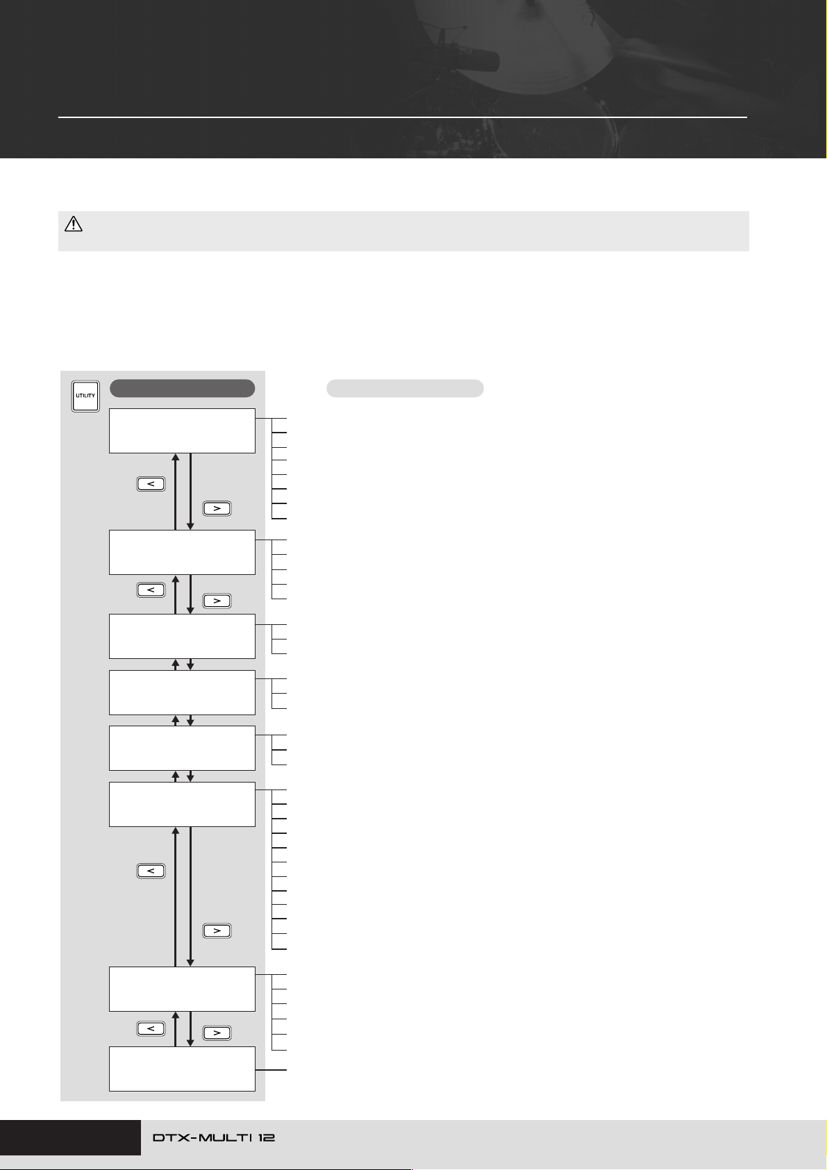
UTILITY Setting Area (UTIL)
This section describes the UTILITY setting area, which can be accessed using the [UTILITY] button. In this area, you
can set parameters affecting the entire instrument and perform a range of file management operations.
CAUTION
• Be sure to store any settings that you have edited before turning off the instrument. (See page 45.)
Makeup of UTILITY Setting Area
The UTILITY setting area is subdivided into three different sections (UTIL1 to UTIL3). Use the [B]/[C] buttons to navigate between
these sections. If a section contains parameter-setting pages, the [ENTER] button will light up. Press the [ENTER] button to access these
pages. In certain cases, a number of additional pages may be accessed from a parameter setting page, also using the lit [ENTER] button.
Furthermore, you can press the [EXIT] button to move back towards the top of the setting area.
Sections
UTIL1
≥≥≥≥GENERAL
UTIL2
≥≥≥≥≥CLICK
UTIL3
≥≥≥MASTER≥EQ
UTIL4
≥≥≥≥≥≥PAD
UTIL5
≥≥≥≥≥HI-HAT
UTIL6
≥≥≥≥≥≥MIDI
Parameter-setting pages
UTIL1-1 Master Volume page ......................................................................... Page 83
UTIL1-2 Master Tune page.............................................................................. Page 83
UTIL1-3 Startup Kit page ................................................................................Page 83
UTIL1-4 Startup Pattern page ......................................................................... Page 83
UTIL1-5 Startup Trigger page.......................................................................... Page 83
UTIL1-6 Effect Bypass page ........................................................................... Page 83
UTIL1-7 Pan Depth page ................................................................................ Page 84
UTIL1-8 Auxiliary Output page........................................................................ Page 84
UTIL2-1 Click-track Voice page ....................................................................... Page 84
UTIL2-2 Click-track Master Volume page........................................................ Page 84
UTIL2-3 Click-track Beat Volume page ...........................................................Page 84
UTIL2-4 Click-track Output page..................................................................... Page 84
UTIL2-5 Click-track MIDI page........................................................................ Page 85
UTIL3-1 Gain, Frequency & Bandwidth page .................................................Page 87
UTIL3-2 EQ Shape page................................................................................. Page 87
UTIL3-3 Master EQ Bypass page ...................................................................Page 87
UTIL4-1 Pad Function page ............................................................................ Page 88
UTIL4-2 Foot Switch Input page .....................................................................Page 89
UTIL4-3 Pad 10-12 Switch page ..................................................................... Page 89
UTIL5-1 Close Position page ..........................................................................Page 89
UTIL5-2 Splash Sensitivity page ..................................................................... Page 89
UTIL5-3 Send Hi-hat Controller page.............................................................. Page 89
UTIL6-1 Channel-10 Receive page................................................................. Page 90
UTIL6-2 Program Change Receive page........................................................ Page 90
UTIL6-3 Channel-10 Program Change Receive page ....................................Page 90
UTIL6-4 Polyphonic Aftertouch Status page ................................................... Page 90
UTIL6-5 Local Control page ............................................................................ Page 90
UTIL6-6 MIDI Sync page................................................................................. Page 91
UTIL6-7 Clock Out page .................................................................................Page 91
UTIL6-8 Sequencer Control page ...................................................................Page 91
UTIL6-9 MIDI In/Out page............................................................................... Page 91
UTIL6-10 MIDI Thru Port page........................................................................ Page 91
UTIL6-11 MIDI Merge page ............................................................................Page 92
UTIL6-12 Device Number page ......................................................................Page 92
82 Owner’s Manual
UTIL7
≥≥≥≥≥≥FILE
UTIL8
≥≥FACTORY≥SET
UTIL7-1 Save File page .................................................................................. Page 93
UTIL7-2 Load File page ..................................................................................Page 94
UTIL7-3 Rename File page............................................................................. Page 96
UTIL7-4 Delete File page ................................................................................ Page 97
UTIL7-5 Format page...................................................................................... Page 97
UTIL7-6 Memory Info page ............................................................................. Page 98
Instrument Reset............................................................................................. Page 98
Page 83
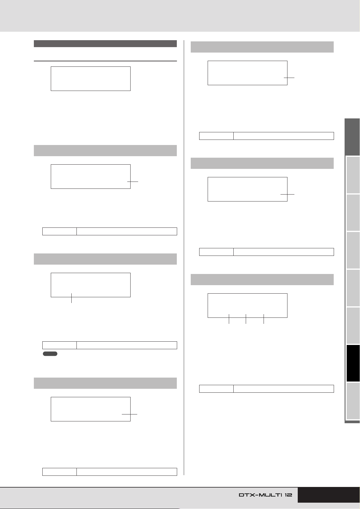
UTILITY Setting Area (UTIL)
UTIL1-4<GENERAL>
StartupPtn=©P001
1
UTIL1-5<GENERAL>
≥StartupTrg=P01
1
UTIL1-6≥≥FXByps=
≥≥var/cho/rev
1 2 3
UTIL1 GENERAL
System Settings
UTIL1
≥≥≥≥GENERAL
In the GENERAL section, you can set parameters affecting the
entire system. With the GENERAL page (UTIL1) displayed,
press the [ENTER] button to access its eight parameter-setting
pages (UTIL1-1 to UTIL1-8). You can use the [B]/[C] buttons
to navigate between these pages.
UTIL1-1 Master Volume page
UTIL1-1<GENERAL>
MasterVolume=127
1 Master volume
Use this parameter to set the master volume of the instrument’s internal tone generator. If a small value is set here, the
VOLUME dial on the front panel will have very little effect in
increasing the output volume.
Settings 0 to 127
UTIL1-2 Master Tune page
1
UTIL1-4 Startup Pattern page
1 Startup pattern (StartupPtn)
Use this parameter to select the pattern that will be automatically set when the DTX-MULTI 12 is turned on. Patterns are
identified using a category (
number, and you can move the cursor using the [B]/[C]
buttons to set these individually.
Settings eP001 to eP128 or eU001 to eU050
e
P for Preset, eU for User) and a
UTIL1-5 Startup Trigger page
1 Startup trigger (StartupTrg)
Use this parameter to select the trigger setup that will be automatically selected when the DTX-MULTI 12 is turned on.
Trigger setups are identified using a category (P for Preset, U
for User) and a number, and you can move the cursor using
the [B]/[C] buttons to set these individually.
Settings P01 to P05 or U01 to U10
UTIL1-2≥≥M.Tune=
+≥≥0.0(440.0Hz)
1
1 Master tune (M.Tune)
Use this parameter to tune (i.e., adjust the basic pitch of) the
internal tone generator. The value in parentheses shows the
corresponding tuning (of A above middle C) in Hertz.
Settings -102.4 to +0.0 to +102.3
NOTE
• The term “cent” refers to one hundredth of a semitone (i.e., 100 cents
= 1 semitone).
UTIL1-3 Startup Kit page
UTIL1-3<GENERAL>
StartupKit=P001
1 StartupKit
Use this parameter to specify the kit to be automatically
selected when the DTX-MULTI 12 is turned on. Kits are
identified using a category (P for Preset, U for User) and a
number, and you can move the cursor using the [B]/[C]
buttons to set these individually.
Settings P001 to P050 or U001 to U200
1
UTIL1-6 Effect Bypass page
1 Variation effect (var)
B Chorus effect (cho)
C Reverb effect (rev)
Use these parameters to specify which effects will be
bypassed when Effect Bypass is activated from the front panel
(using the [SHIFT] and [KIT] buttons). When “---” is selected
for an effect type, it will not be bypassed.
Settings ---/var, ---/cho, or ---/rev
TRIGGER ReferenceKITMIDI VOICEUTILITY WAVEPATTERN
Owner’s Manual 83
Page 84
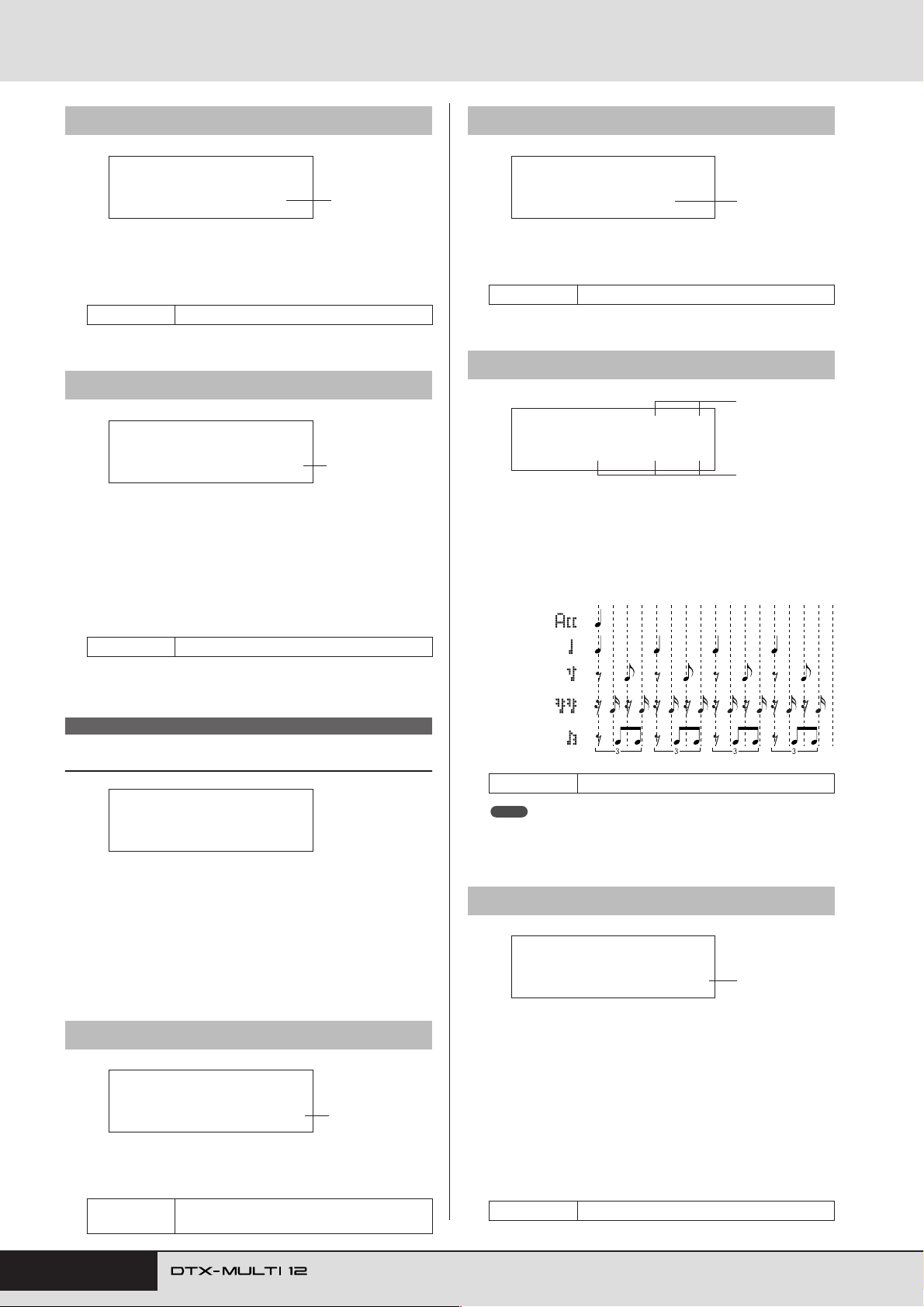
UTILITY Setting Area (UTIL)
UTIL1-7 Pan Depth page
UTIL1-7<GENERAL>
≥≥PanDepth=≥64
1 Pan depth
Use this parameter to adjust the width of the instrument’s
overall stereo-panning field while maintaining the individual
pan settings for drum and musical instrument sounds.
Settings 1 to 127
UTIL1-8 Auxiliary Output page
1
UTIL1-8<GENERAL>
AuxOutSel=L&R+ph
1 Auxiliary output selection (AuxOutSel)
Use this parameter to indicate where audio input via the AUX
IN jack will be output.
• L&R+ph ............. Auxiliary-input audio will be output via
both the OUTPUT (L/MONO and R) and
PHONES jacks.
• phones ................ Auxiliary-input audio will be output via
the PHONES jack only.
Settings L&R+ph or phones
1
UTIL2-2 Click-track Master Volume page
UTIL2-2≥≥<CLICK>
≥≥≥Volume=127
1 Click-track master volume
Use this parameter to set the master volume for click-track
sounds.
Settings 0 to 127
UTIL2-3 Click-track Beat Volume page
1
1
UTIL2-3≥A…=9≥ƒ=9
≥≥≥≥∫=0≥ææ=0≥ø=0
1
1 Click-track beat volumes
Use these parameters to set volumes for different beat timings
within the click track. The meanings of the symbols used on
this page are shown below.
Example: Beat timings for four beats per bar
Accents
th
4 notes
th
8 notes
UTIL2 CLICK
Click Track Settings
UTIL2
≥≥≥≥≥CLICK
In the CLICK section, you can set parameters related to the click
track. For example, you can set the type of sound to be used, the
volume, and where the click track will be output. MIDI parameters related to the click track can also be set here. With the CLICK
page (UTIL2) displayed, press the [ENTER] button to access its
five parameter-setting pages (UTIL2-1 to UTIL2-5). You can use
the [B]/[C] buttons to navigate between these pages.
UTIL2-1 Click-track Voice page
UTIL2-1≥≥<CLICK>
Voice=Metronome1
1 Click-track voice
Use this parameter to select from a range of different sounds
for use with the click track.
Settings
Metronome1, Metronome2, Cowbell, Stick,
Human
1
th
16 notes
th
8 note triplets
Settings 0 to 9
NOTE
• If the time signature from the PATTERN setting area or for pattern
recording is 3/8, 6/8, 9/8, 12/8, or 15/8, this page will display ACC, dotted quarter notes, eighth notes, and sixteenth notes.
UTIL2-4 Click-track Output page
UTIL2-4≥≥<CLICK>
ClkOutSel=phones
1 Click-track output selection (ClkOutSel)
Use this parameter to specify where the click track will be
output when activated. In a live-performance setting, for
example, you would normally want the click track to be output to headphones only, and in such a case, “phones” should
be selected here.
• L&R+ph ............. The click-track will be output via both the
OUTPUT (L/MONO and R) and
PHONES jacks.
• phones ................ The click-track will be output via the
PHONES jack only.
Settings L&R+ph, phones
1
84 Owner’s Manual
Page 85
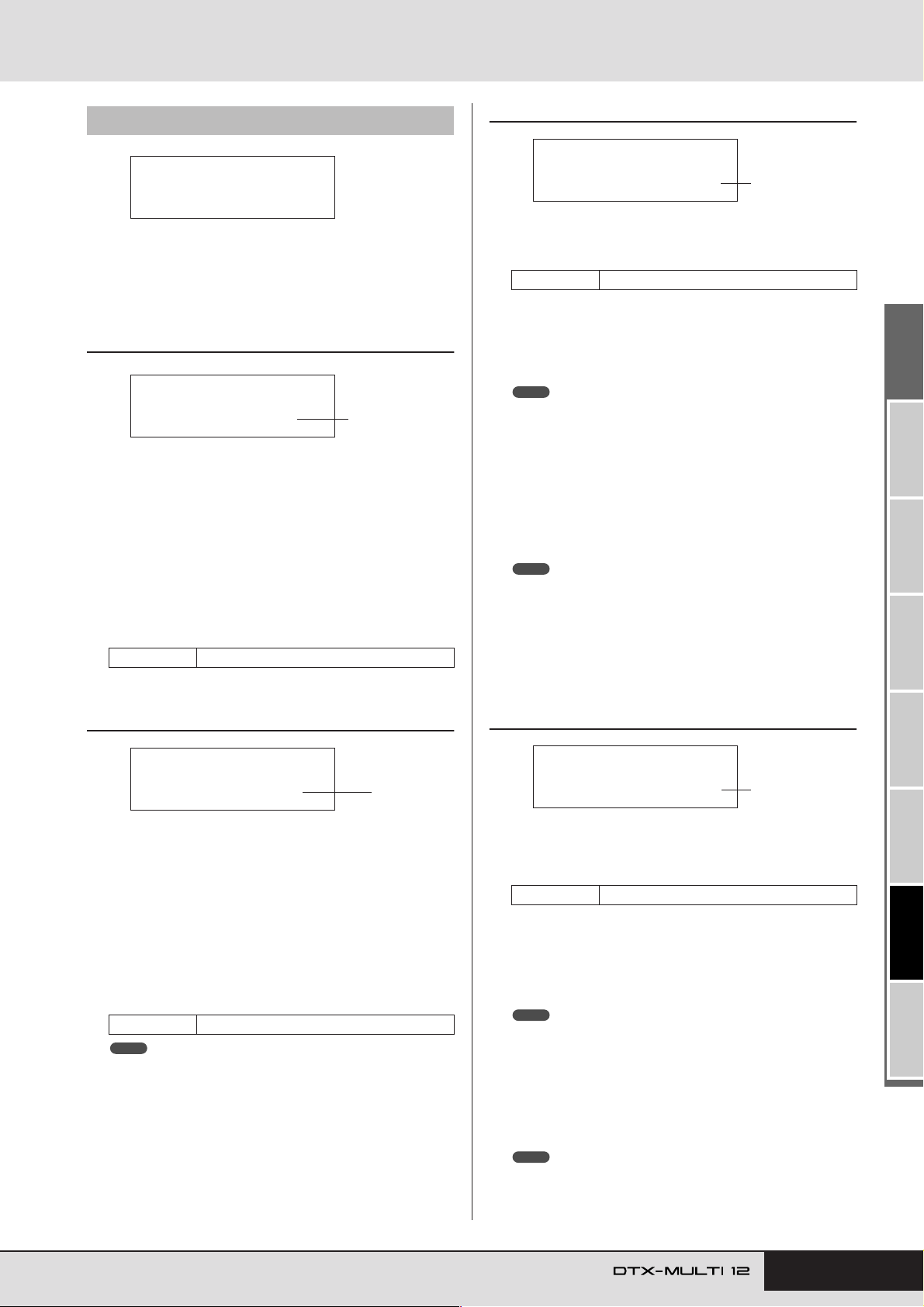
UTILITY Setting Area (UTIL)
UTIL2-5-3<CLICK>
NoteA…=C#-1/≥13
1
UTIL2-5-4<CLICK>
≥Noteƒ=C#-1/≥13
1
UTIL2-5 Click-track MIDI page
UTIL2-5
≥≥≥Click≥MIDI
From the Click-track MIDI page (UTIL2-5), you can set a range
of MIDI parameters related to the click track. With this page displayed, press the [ENTER] button to access a further four parameter-setting pages (UTIL2-5-1 to UTIL2-5-4). You can use the
[B]/[C] buttons to navigate between these pages.
UTIL2-5-1 Click-track MIDI In page
UTIL2-5-1<CLICK>
≥≥MIDI≥IN=off
1 MIDI IN
Use this parameter to specify whether or not click-track
sounds are to be produced based on MIDI Note On messages
received via the MIDI IN connector. When set to “on”, the
DTX-MULTI 12 operates as follows:
•A click-track accent sound will be produced upon the
receipt of a MIDI note with the note number set on the
Accent Note Number page (UTIL2-5-3).
•A click-track quarter note sound will be produced upon the
receipt of a MIDI note with the note number set on the
Quarter-Note Note Number page (UTIL2-5-4).
Settings off or on
1
UTIL2-5-3 Accent Note Number page
1 Accent note number (NoteAcc)
Use this parameter to assign a MIDI note number to clicktrack accent sounds.
Settings off or C#-2 to F#8
• If “on” is selected on the Click-track MIDI In page
(UTIL2-5-1), a click-track accent sound will be produced
each time a MIDI note with the note number set here is
received.
NOTE
• If “off” is selected on this page (UTIL2-5-3), no click-track accent
sounds will be produced in response to received MIDI notes.
• If the same value is set on this page (UTIL2-5-3) and on the Quarter-
Note Note Number page (UTIL2-5-4), the same sound will be produced for all beat timings.
• If “on” is selected on the Click-Track MIDI Out page
(UTIL2-5-2), a MIDI Note On message with the note number set here will be produced for each click-track accent
sound.
NOTE
• If “off” is selected both on this page (UTIL2-5-3) and on the Quarter-
Note Note Number page (UTIL2-5-4), no MIDI Note On messages will
be output for click-track sounds. If, however, “off” is selected on this
page (UTIL2-5-3) but a setting other than “off” is selected on the Quarter-Note Note Number page (UTIL2-5-4), MIDI Note On messages
with the corresponding note number will be output for all click-track
sounds.
UTIL2-5-2 Click-Track MIDI Out page
UTIL2-5-2<CLICK>
≥≥MIDI≥OUT=off
1 MIDI OUT
Use this parameter to turn the output of click-track MIDI
events (i.e., MIDI Note On messages) on and off. When set to
“on”, the DTX-MULTI 12 operates as follows:
•A MIDI note with the note number set on the Accent Note
Number page (UTIL2-5-3) will be produced for each clicktrack accent sound.
•A MIDI note with the note number set on the Quarter-Note
Note Number page (UTIL2-5-4) will be produced for each
click-track quarter note sound.
Settings off or on
NOTE
• Regardless of this parameter’s setting, no MIDI Note On messages
can be produced for click-track sounds other than accents and quarter
notes.
1
UTIL2-5-4 Quarter-Note Note Number page
1 Quarter-note note number (Noteqq
qq
)
Use this parameter to assign a MIDI note number to clicktrack quarter note sounds.
Settings off or C#-2 to F#8
• If “on” is selected on the Click-track MIDI In page
(UTIL2-5-1), a click-track quarter-note sound will be produced each time a MIDI note with the note number set here
is received.
NOTE
• If “off” is selected on this page (UTIL2-5-4), no click-track quarter-note
sounds will be produced in response to received MIDI notes.
• If “on” is selected on the Click-Track MIDI Out page
(UTIL2-5-2), a MIDI Note On message with the note number set here will be produced for each click-track quarternote sound.
NOTE
• If “off” is selected on this page (UTIL2-5-4), no MIDI Note On mes-
sages will be produced for click-track quarter-note sounds.
TRIGGER ReferenceKITMIDI VOICEUTILITY WAVEPATTERN
Owner’s Manual 85
Page 86
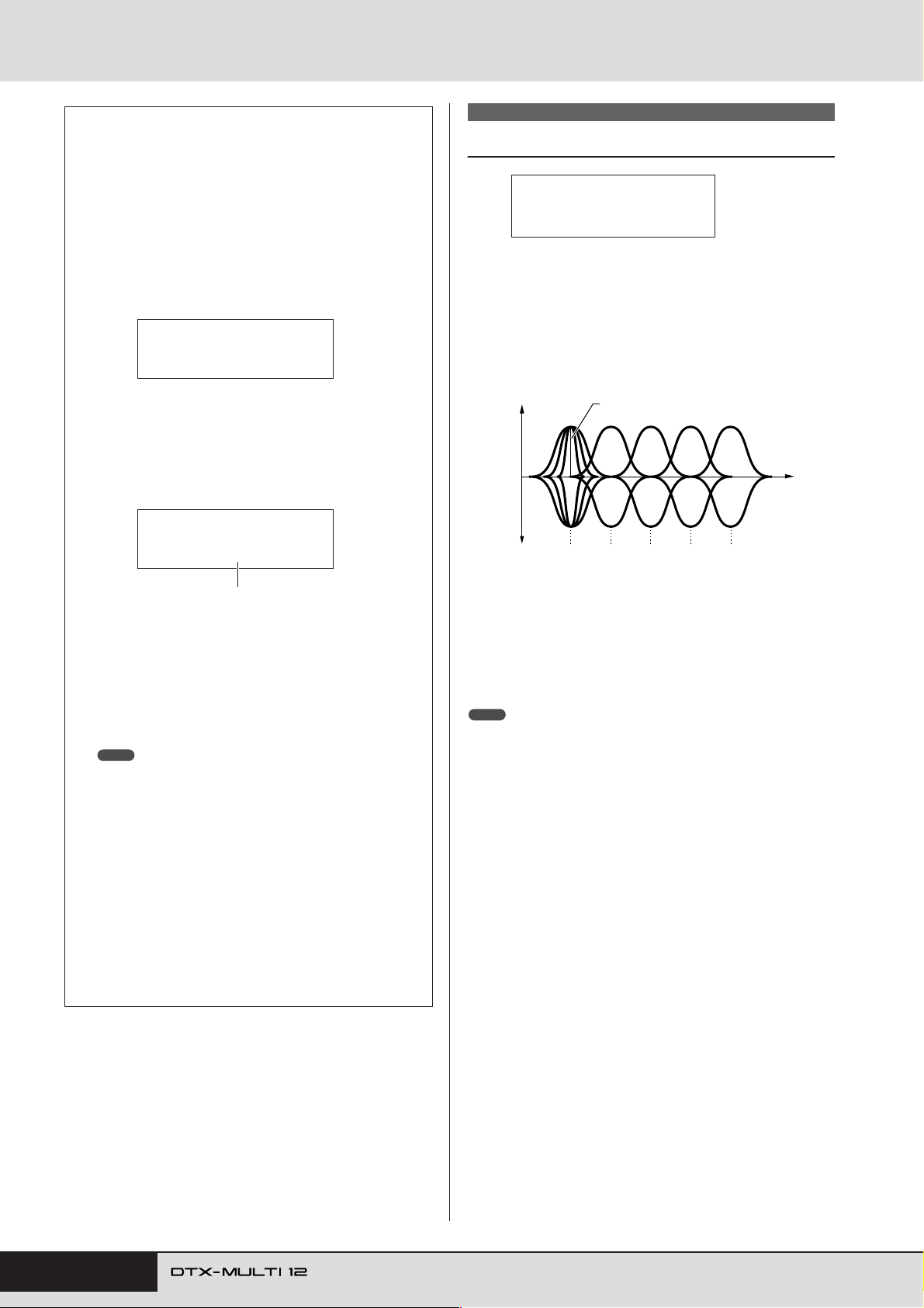
UTILITY Setting Area (UTIL)
Tap Tempo
Using the Tap Tempo function, you can set the tempo for patterns and the click track by simply striking pads. In this way,
you can conveniently and intuitively set the tempo that you
need.
Hold down the [SHIFT] button and press the
1
EE
[EE
] (click) button.
The Tap Tempo page will open displaying the current
tempo setting.
TAP≥TEMPO
≥≥≥≥≥ƒ=120
Strike one or more of the pads several times at
2
the required tempo.
The DTX-MULTI 12 will automatically determine the
tempo based on the speed at which you strike the pads, and
this tempo will be displayed on-screen.
TAP≥TEMPO
≥≥≥≥≥ƒ=158
Tempo: 30 to 300
To check the tempo, press the [EE
3
ton to start the click track.
The click track will be played at the tempo set using the
Tap Tempo function. Whenever you change the tempo
using this function, the new setting will be immediately
applied to the click track and any patterns being played.
NOTE
• The [-/DEC] and [+/INC] buttons can also be used to adjust the
tempo on the Tap Tempo page.
• If Func has been set to “tap tempo” for any of the pads on the
UTILITY area’s Pad Function page (UTIL4-1), that pad can be
used at any time to tap the tempo without having to open the Tap
Tempo page (see page 88).
• If “ext” has been selected on the UTILITY area’s MIDI Sync page
(UTIL 6-6) or if “auto” has been selected on that page and MIDI
Clock messages are being received from an external source, the
tempo value will be displayed as “ext” and playback on your DTXMULTI 12 will be synchronized with the connected MIDI devices or
DAW application.
• If “int” has been selected on the UTILITY area’s MIDI Sync page
(UTIL 6-6) or if “auto” has been selected on that page and MIDI
Clock messages are not being received from an external source,
playback will occur at the DTX-MULTI 12’s current tempo setting
(see page 91).
EE
] (click) but-
UTIL3 MASTER EQ
Master Equalization
UTIL3
≥≥≥MASTER≥EQ
In the MASTER EQ section, you can adjust the master equalization parameters that control the tone of all preset voices, patterns,
and waves. With the MASTER EQ page (UTIL3) displayed, press
the [ENTER] button to access its three parameter-setting pages
(UTIL3-1 to UTIL3-3). You can use the [B]/[C] buttons to nav-
igate between these pages.
Gain (G)
+
0
–
The DTX-MULTI 12 features a five-band master equalizer that
allows the signal level to be freely boosted or cut around a center
frequency specified for each of the bands. In addition, the “low”
and “high” frequency bands can be set to either shelving or peaking equalization.
NOTE
• Master equalization has no effect on signals from the AUX IN connector.
(See page 36)
• Master equalization has no effect on signals output via the PHONES jack.
(See page 36)
Q (Bandwidth)
F (Frequency)
low highhighMidmidlowMid
Five EQ bands
86 Owner’s Manual
Page 87
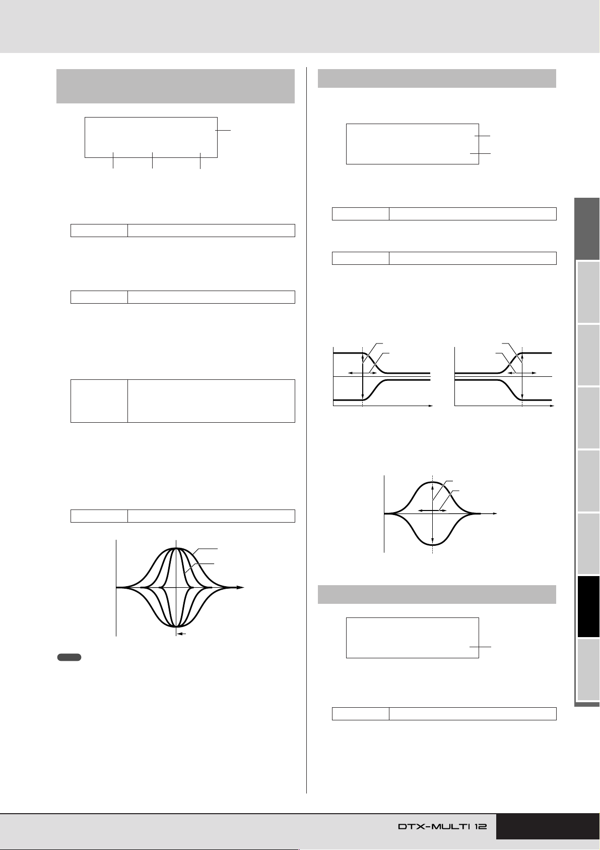
UTILITY Setting Area (UTIL)
UTIL3-2≥≥≥≥≥≥low
≥Shape=shelving
1
2
–
+
0
–
+
0
EQ low EQ high
G (Gain)
F (Frequency)
G (Gain)
F
(Frequency)
Frequency Frequency
–
+
0
G (Gain)
F (Frequency)
Frequency
UTIL3-3
≥MEQ≥Bypass=off
1
UTIL3-1 Gain, Frequency & Bandwidth
page
UTIL3-1≥≥≥≥≥≥mid
1
G+12/F2.0k/Q≥0.1
2
1 Frequency band
Use this parameter to select the master-EQ frequency band to
be set.
Settings low, lowMid, mid, highMid, or high
B Gain (G)
Use this parameter to specify the amount by which the signal
level in the frequency band indicated by 1 will be boosted or
cut.
Settings -12 to +0 to +12
C Frequency (F)
Use this parameter to specify the frequency within the band
indicated by 1 around which the signal level will be cut or
boosted. If the “low” band has been selected, the range of
available frequencies will depend on the EQ type set using the
Shape parameter on the EQ Shape page (UTIL3-2).
Settings
3
32 to 2.0k for “shelving”
low:
63 to 2.0k for “peaking”
lowMid, mid, and highMid: 100 to 10k
high: 500 to 16k
4
UTIL3-2 EQ Shape page
On the EQ Shape page, you can set an EQ type for each of the
“low” and “high” bands.
1 Frequency band
Use this parameter to select the master-EQ frequency band to
be set.
Settings low or high
B Shape
Use this parameter to set an EQ type.
Settings shelving or peaking
● shelving:
Signals at all frequencies either above or below the specified
frequency will be boosted or cut.
D Bandwidth (Q)
Use this parameter to specify a width for the band of frequencies to be boosted or cut. If you set a large value, a narrower
band of frequencies will be affected and the tone will change
markedly around the center frequency. If you set a smaller
value, a wider band of frequencies will be affected and the
tone will change gradually around the center frequency.
Settings 0.1 to 12.0
+
0
–
F (Frequency)
NOTE
• When “low” or “high” is indicated by 1 and “shelving” has been set using
the Shape parameter on the EQ Shape page (UTIL3-2), the setting for
Bandwidth (Q) will be displayed as “---” and modification will not be possible.
Q = 0.1
Q = 12.0
Frequency
● peaking:
Signals within a band of frequencies around the specified frequency will be boosted or cut.
UTIL3-3 Master EQ Bypass page
1 Master EQ bypass (MEQBypass)
Use this parameter to specify whether the master EQ will be
bypassed (“on”) or applied (“off”).
Settings off or on
TRIGGER ReferenceKITMIDI VOICEUTILITY WAVEPATTERN
Owner’s Manual 87
Page 88
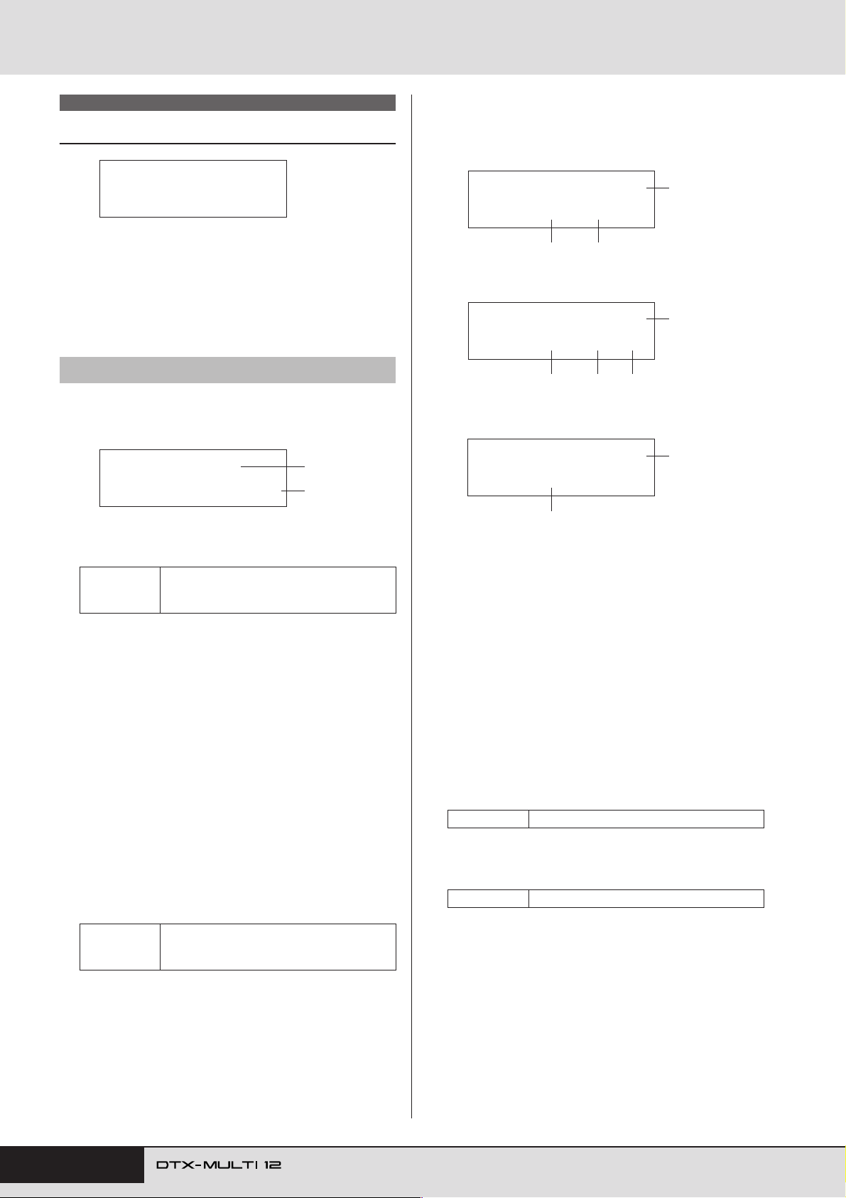
UTILITY Setting Area (UTIL)
UTIL4 PAD
Pad Utilities
UTIL4
≥≥≥≥≥≥PAD
In the PAD section, you can assign functions to pads and external
controllers, specify the type of controller connected via the FOOT
SW jack, and enable or disable rim pads 10 to 12. With the PAD
page (UTIL4) displayed, press the [ENTER] button to access its
three parameter-setting pages (UTIL4-1 to UTIL4-3). You can use
the [B]/[C] buttons to navigate between these pages.
UTIL4-1 Pad Function page
On the Pad Function page, you can specify operations to be performed when individual pads or external controllers are struck or
operated.
UTIL4-1≥-º¡Func=clickOn/Off
1
2
When a MIDI Control Change message (CC01 to CC95) is
specified as the pad function, control-change values and the
MIDI send channel are set as follows.
If setting a pad or external controller other than “FTSW”:
UTIL4-1≥-º¡-≥≥†”
4
Func=CC01/127
2 3
If setting “FTSW” and “ftSw” is selected on the
Foot Switch Input page (UTIL4-2):
UTIL4-1≥-√¤‘’-†”
4
Func=CC01/≥0-127
3-b
2
If setting “FTSW” and “ftSw” is not selected on the
Foot Switch Input page (UTIL4-2):
UTIL4-1≥-√¤‘’-†”
3-a
4
Func=CC01
1 Pad number
Use this parameter to select the pad or external controller to
be set. You can also strike a pad to select it.
01 to 12, 13, 13R1, 13R2, 14 to 17, FTSW
Settings
(foot switch), HHCL (hi-hat close), or HHSP
(hi-hat splash)
B Pad function (Func)
Use this parameter to set the operation to be performed when
the pad or external controller indicated by 1 is struck or
operated.
•off ....................... Voices will be played in the normal way.
• inc kitNo............. The kit number will be increased by 1.
• dec kitNo ............The kit number will be decreased by 1.
• inc ptnNo ............ The pattern number will be increased by
1.
• dec ptnNo ........... The pattern number will be decreased by
1.
• inc tempo ............ The tempo will be increased by 1 bpm.
• dec tempo ........... The tempo will be decreased by 1 bpm.
• tap tempo ............The pad or external controller can be used
to tap the tempo.
• clickOn/Off......... The click track will be turned on or off.
• CC01 to CC95 .... A MIDI Control Change message will be
sent to the internal tone generator and
connected external MIDI devices.
off, inc kitNo, dec kitNo, inc ptnNo, dec
Settings
ptnNo, inc tempo, dec tempo, tap tempo,
clickOn/Off, or CC01 to CC95
2
C Control change value
Use this parameter to set a value for the MIDI control-change
message indicated by 2.
• If setting a pad or external controller other than
“FTSW”: This value will be sent when the pad or external
controller is struck or operated.
• If setting “FTSW” and “ftSw” is selected on the Foot
Switch Input page (UTIL4-2): 3-a is the value that will
be sent when the foot switch is released, and 3-b is the
value that will be sent when the foot switch is depressed.
• If setting “FTSW” and “ftSw” is not selected on the
Foot Switch Input page (UTIL4-2): A specific controlchange value cannot be specified in this case. Instead, a
value within the range 0 to 127 will be sent based on the
degree by which the hi-hat controller or foot controller is
operated.
Settings 0 to 127
D Control-change send channel
Use this parameter to set a MIDI channel for sending the
MIDI Control Change message indicated by 2.
Settings 1 to 16
88 Owner’s Manual
Page 89
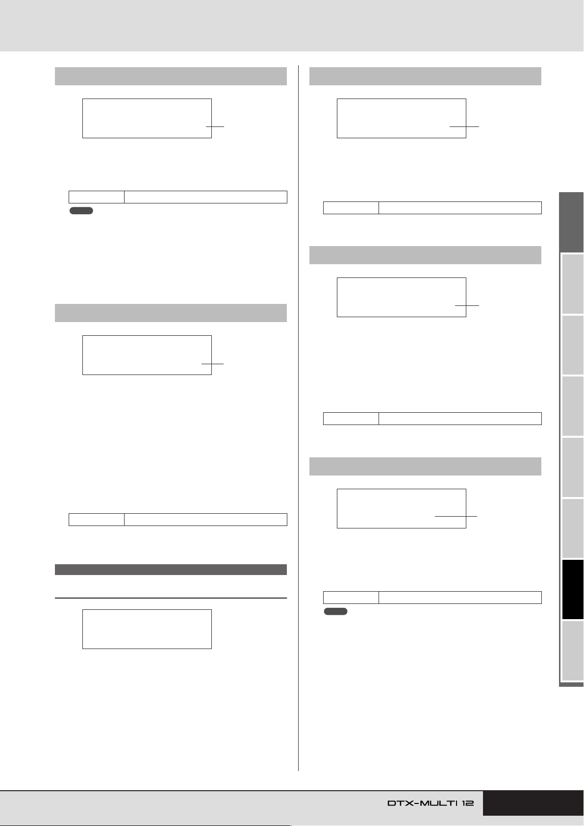
UTILITY Setting Area (UTIL)
UTIL5-1≥<HI-HAT>
≥ClosePosi=+10
1
UTIL5-2≥<HI-HAT>
≥SplashSens=127
1
UTIL5-3≥<HI-HAT>
≥≥≥SendHH=on
1
UTIL4-2 Foot Switch Input page
UTIL4-2≥≥≥≥<PAD>
FootSwInSel=ftSw
1 Foot switch input selection (FootSwInsel)
Use this parameter to specify whether a foot switch (“ftSw”),
a hi-hat controller (“HH65”), or a foot controller (“FC7”) is
connected via the FOOT SW jack.
Settings ftSw, HH65, or FC7
NOTE
• The velocities sent when a hi-hat controller or a foot controller is connected will depend on the setting made on the Trigger Velocity page
(MIDI1-7).
• The velocities sent when a foot switch is connected also depend on
the setting made on the Trigger Velocity page (MIDI1-7); however, if
“variable” is selected on that page, velocities will be sent with a fixed
value of 100.
UTIL4-3 Pad 10-12 Switch page
1
UTIL4-3≥≥≥≥<PAD>
Pad10-12=enable
1 Pad10-12
Use this parameter to turn rim pads 10 to 12 on (“enable”) or
off (“disable”). This function can prove useful in preventing
voices assigned to these rim pads from being played when
they are accidentally struck instead of pads 7 to 9.
• enable ................. The rim pads will operate in the normal
way.
• disable ................ Functions assigned to these rim pads will
be disabled. When they are struck, the
DTX-MULTI 12 behaves in the same way
as if the corresponding main pads (7 to 9)
had been struck.
Settings enable or disable
1
UTIL5-1 Close Position page
1 Close position (ClosePosi)
Use this parameter to adjust the position at which the hi-hat
switches from open to closed when a hi-hat controller is
depressed. The lower the value, the smaller the virtual opening between the top and bottom hi-hats.
Settings -32 to +0 to +32
UTIL5-2 Splash Sensitivity page
1 Splash sensitivity (SplashSens)
Use this parameter to set the degree of sensitivity for detecting hi-hat foot splashes. The higher the value, the easier it will
be to produce foot-splash sounds with the hi-hat controller.
High values may, however, result in splash sounds being unintentionally produced when, for example, you depress the hihat controller lightly to keep time. It is a good idea to set this
parameter to “off” if you do not want to play foot splashes.
Settings off or 1 to 127
UTIL5-3 Send Hi-hat Controller page
UTIL5 HI-HAT
Hi-hat Setup
UTIL5
≥≥≥≥≥HI-HAT
In the HI-HAT section, you can set parameters related to hi-hats.
With the HI-HAT page (UTIL5) displayed, press the [ENTER]
button to access its three parameter-setting pages (UTIL5-1 to
UTIL5-3). You can use the [B]/[C] buttons to navigate between
these pages.
1 Send hi-hat controller (SendHH)
Use this parameter to enable (“on”) or disable (“off”) the
sending of MIDI messages corresponding to continuous
motion of the hi-hat controller between the open and closed
positions.
Settings off or on
NOTE
• If “hi-hat” is selected on the Hi-Hat Function page (KIT7-3), MIDI messages will be sent only when this parameter is set to “on”.
• If “MIDI” is selected on the Hi-Hat Function page (KIT7-3), MIDI messages will always be sent, regardless of whether this parameter is set
to “on” or “off”.
TRIGGER ReferenceKITMIDI VOICEUTILITY WAVEPATTERN
Owner’s Manual 89
Page 90
UTILITY Setting Area (UTIL)
UTIL6 MIDI
Instrument MIDI Setup
UTIL6
≥≥≥≥≥≥MIDI
In the MIDI section, you can set MIDI parameters affecting the
entire DTX-MULTI 12 system. With the MIDI page (UTIL6) displayed, press the [ENTER] button to access its twelve parameter-
setting pages (UTIL6-1 to UTIL6-12). You can use the [B]/[C]
buttons to navigate between these pages.
UTIL6-1 Channel-10 Receive page
UTIL6-1≥≥≥<MIDI>
≥≥Rcv10ch=on
1 Channel-10 receive (Rcv10ch)
Use this parameter to enable (“on”) or disable (“off”) the
receipt of MIDI messages sent by external devices on Channel 10. If set to “off”, the internal tone generator will play
voices on Channel 10 in response only to input from the
DTX-MULTI 12’s pads and from pads connected via the PAD
jacks.
Settings off or on
UTIL6-2 Program Change Receive page
1
UTIL6-3
Channel-10 Program Change
Receive page
UTIL6-3≥≥≥<MIDI>
≥RcvPC10ch=on
1 Channel-10 program change receive
(RcvPC10ch)
Use this parameter to enable (“on”) or disable (“off”) the
receipt of MIDI Program Change messages sent on MIDI
channel 10. Select “on” if you want kits to change in line with
pattern settings or in response to signals from external MIDI
devices. Note that this setting is effective only when “on” is
also selected on the Program Change Receive page (UTIL6-
2).
Settings off or on
UTIL6-4 Polyphonic Aftertouch Status
1
page
UTIL6-4≥≥≥<MIDI>
≥PolyAfter=on
1 Polyphonic aftertouch status (PolyAfter)
Use this parameter to enable (“on”) or disable (“off”) the
exchange of polyphonic aftertouch messages with external
MIDI devices.
Settings off or on
1
UTIL6-2≥≥≥<MIDI>
≥≥≥RcvPC=on
1 Program change receive (RcvPC)
Use this parameter to enable (“on”) or disable (“off”) the
receipt of MIDI Program Change messages. If set to “off” and
a new drum kit is selected, voices will be changed only based
on settings made for that kit’s preset voices. If you want
voices on all MIDI channels to change in line with pattern settings or in response to signals from external MIDI devices,
this parameter should be set to “on”.
Settings off or on
1
UTIL6-5 Local Control page
UTIL6-5≥≥≥<MIDI>
≥LocalCtrl=on
1 Local control (LocalCtrl)
Use this parameter to enable (“on”) or disable (“off”) playing
of the internal tone generator using DTX-MULTI 12 pads and
patterns. Normally, this is set to “on”, meaning that the tone
generator is locally controlled. If set to “off,” the pads and
external controllers are essentially disconnected from the
internal tone generator – in other words, no sound is produced
by the DTX-MULTI 12 when you strike them.
NOTE
•Even if local control is disabled (i.e., set to “off”) on this page, the DTXMULTI 12’s internal tone generator can produce sound in response to
MIDI messages received via the MIDI IN connector and the USB TO
HOST port; furthermore, MIDI messages produced by pads, patterns,
and external controllers will be output via the MIDI OUT connector.
Settings off or on
1
90 Owner’s Manual
Page 91
UTILITY Setting Area (UTIL)
UTIL6-8≥≥≥<MIDI>
≥SeqCtrl=in/out
1
UTIL6-9≥≥≥<MIDI>
MIDI≥IN/OUT=MIDI
1
UTIL6-10≥≥<MIDI>
≥≥≥ThruPort=1
1
UTIL6-6 MIDI Sync page
UTIL6-6≥≥≥<MIDI>
≥MIDI≥Sync=int
1 MIDI synchronization (MIDISync)
Use this parameter to specify whether patterns and the click
track are to play at the tempo set for the DTX-MULTI 12 or
are to be synchronized with external MIDI devices based on
MIDI Clock messages (i.e., F8 Timing Clock) received from
them.
• int ........ Patterns and the click track will play at the current
DTX-MULTI 12 tempo setting. Use “int” when this
instrument is to be used alone or as the master
clock source for other equipment.
•ext........ The DTX-MULTI 12 will be synchronized with
MIDI Clock messages received via MIDI. Use
“ext” when an external MIDI device is to be used as
the master clock source for synchronized playback.
• auto...... MIDI Clock messages received via MIDI will be
prioritized over the DTX-MULTI 12’s current
tempo. In other words, playback will be synchronized to MIDI Clock messages whenever they are
received, and the internal tempo will be used in all
other cases.
Settings int, ext, or auto
NOTE
• In order to successfully synchronize the DTX-MULTI 12 whenever this
parameter is set to “ext” or “auto”, the connected external MIDI device
or computer must be setup to send MIDI Clock messages.
UTIL6-7 Clock Out page
1
UTIL6-8 Sequencer Control page
1 Sequencer control (SeqCtrl)
Use this parameter to specify whether or not System Realtime
messages (i.e., FA Start, FB Continue, and FC Stop) will be
sent and received via MIDI.
•off .........System Realtime messages are neither sent nor
received.
•in..........System Realtime messages are received but not
sent.
• out ........System Realtime messages are sent but not
received.
• in/out ....System Realtime messages are sent and received.
Settings off, in, out, or in/out
NOTE
• If “strt”, “cont”, or “stop” has been set on the MIDI Message page
(MIDI1), the SeqCtrl setting 1 will have no effect and the respective
message (i.e., FA Start, FB Continue, or FC Stop) will be output.
UTIL6-9 MIDI In/Out page
1 MIDI IN/OUT
Use this parameter to specify whether the exchange of MIDI
messages with external devices is to be performed via the
MIDI connectors or the USB TO HOST port.
Settings MIDI or USB
UTIL6-7≥≥≥<MIDI>
≥≥ClockOut=on
1 Clock out
Use this parameter to enable (“on”) or disable (“off”) the
sending of MIDI Clock messages (i.e., F8 Timing Clock) via
the MIDI OUT connector.
Settings off or on
1
UTIL6-10 MIDI Thru Port page
1 MIDI Thru port (ThruPort)
When the DTX-MULTI 12 receives MIDI messages from a
computer connected via USB, it can relay those messages
received via a specific port to the MIDI OUT connector so
that they can be output to other external MIDI devices. Use
this parameter to specify that port.
Settings 1 or 2
TRIGGER ReferenceKITMIDI VOICEUTILITY WAVEPATTERN
Owner’s Manual 91
Page 92
UTILITY Setting Area (UTIL)
UTIL6-11 MIDI Merge page
UTIL6-11≥≥<MIDI>
≥≥≥Merge=off
1 MIDI merge
The MIDI Merge function allows you to mix MIDI messages
received via the MIDI IN connector with performance data
produced by playing the DTX-MULTI 12, and to output this
mixed MIDI data via the MIDI OUT connector. Set this
parameter to “on” to enable this merging of MIDI messages.
Settings off or on
NOTE
• If “USB” has been selected on the MIDI In/Out page (UTIL6-9), this
setting will be displayed as “---” and modification will not be possible.
UTIL6-12 Device Number page
1
UTIL6-12≥≥<MIDI>
≥DeviceNo.=all
1 Device number
Use this parameter to set a MIDI device number for the DTXMULTI 12. In order to successfully exchange bulk data,
parameter changes, and other system exclusive MIDI messages, this setting must match the Device Number of the
external MIDI device.
• all......... System exclusive messages for all MIDI device
numbers will be received. In addition, the DTXMULTI 12 will transmit messages using Device
Number 1.
•off ........ System exclusive messages such as bulk dump and
parameter changes will be neither transmitted nor
received. An error message will be displayed if an
attempt is made to perform such an operation.
Settings 1 to 16, all, or off
1
UTIL7 FILE
File Management
UTIL7
≥≥≥≥≥≥FILE
In the FILE section, you can perform a range of file-management
operations. With the FILE page (UTIL7) displayed, press the
[ENTER] button to access its six parameter-setting pages
(UTIL7-1 to UTIL7-6). You can use the [B]/[C] buttons to nav-
igate between these pages.
File-related terms
A number of terms will be used in the following descriptions of
file management functions and operations. Please take a moment
to familiarize yourself with their meanings in order that these
functions and operations can be more easily understood.
File
The term “file” is used to define a collection of data stored on a
USB memory device or within the DTX-MULTI 12’s internal
memory. The exchange of data with USB memory devices is carried out in the form of files.
File name
As with your computer, the DTX-MULTI 12 can assign names to
individual files. These names are used to tell files apart, and for
this reason, no two files within a specific directory can share the
same file name. Although computers can handle very long file
names that can even contain non-English characters, the DTXMULTI 12 requires that names be limited to eight alphanumeric
characters.
File extension
The three letters following the period at the end of a file name –
such as “.mid” and “.wav” – are referred to as a “file extension.”
The type of data contained within the file is identified by the file
extension. Please note that, although this instrument assigns file
extensions to file names, they are not displayed on-screen in order
to allow the available space to be used more efficiently.
92 Owner’s Manual
File size
The amount of memory needed to store a file is indicated by the
file size. These sizes and also the capacities of memory devices
are presented in standard computer format using B (bytes), KB
(kilo bytes), MB (mega bytes), and GB (giga bytes). (1 KB is
equivalent to 1,024 bytes, 1 MB is equivalent to 1,024 KB, and 1
GB is equivalent to 1,024 MB.)
USB memory device
The term “USB memory device” is used to refer to hard disks and
other external USB memory units used for the storage and
retrieval of files.
Page 93
UTILITY Setting Area (UTIL)
UTIL7-1≥≥≥<FILE>
≥≥≥Save≥File
UTIL7-1-1≥<FILE>
Type=All
File type
UTIL7-1-2≥<FILE>
Name=[ALL_DATA]
File name
Directory
A hierarchical directory system is used on memory devices in
order to group files together according to type or application. In
this regard, a “directory” is equivalent to a folder as used on a
computer. As with files, you can assign names to individual directories. File operations are carried out inside a set of special directories that are created as follows within a USB memory device
when it is formatted for use on the Format page (UTIL7-5).
Please note that the DTX-MULTI 12 does not display this directory structure on-screen.
\YAMAHA
DTXMULTI
ALL All
ALLKIT AllKit
ALLWAV AllWave
ALLPTN AllPattern
ALLTRG AllTrigger
UTL Utility
Format
The operation of initializing a USB memory device is referred to
as “formatting”. Whenever you format a USB memory device
using this instrument, any previously created files and directories
(or folders) will be erased and the special directories shown above
will be created.
Save and Load
The term “save” refers to the writing of data created on the DTXMULTI 12 to a USB memory device for storage, while “load”
refers to the reading of files from the memory device into the
instrument’s internal memory. From the Save File page, you can
save files on a USB memory device as follows.
UTIL7-1 Save File page
From the Save File page, you can save files on a USB memory
device as follows.
Plug a USB memory device formatted for use with
1
the DTX-MULTI 12 on the Format page (UTIL7-5) into
the USB TO DEVICE port on the side of the instrument.
Navigate to the Save File page (UTIL7-1) and press
2
the [ENTER] button.
The Type page (UTIL7-1-1) will open.
The Type parameter specifies the types of file to be saved.
• All .......................All user data – i.e., all User kits, all
waves, all User patterns, all User triggers,
and utility settings.
• AllKit ..................All User-kit data
• AllWave ..............All wave data
• AllPattern............All User-pattern data
• AllTrigger ...........All User-trigger data
• Utility..................Utility settings
Settings
NOTE
• If you select “AllPattern” despite User patterns having not yet being
created, a “No Data” error message will be displayed and no data will
be saved.
• If you select “AllWave” despite all waves still being empty, a “No Wave
Data” error message will be displayed and no data will be saved.
All, AllKit, AllWave, AllPattern, AllTrigger, or
Utility
Specify a file type using the Type parameter, and
3
press the [ENTER] button.
The Name page (UTIL7-1-2) will open. Set a name for the file
to be saved.
The [B]/[C] buttons can be used to move the flashing cur-
sor, and the [-/DEC] and [+/INC] buttons can be used to scroll
through the available characters. File names can be up to eight
characters long.
NOTE
•Any space characters included in file names will be automatically
replaced with “_” (i.e., an underscore).
Owner’s Manual 93
TRIGGER ReferenceKITMIDI VOICEUTILITY WAVEPATTERN
Page 94
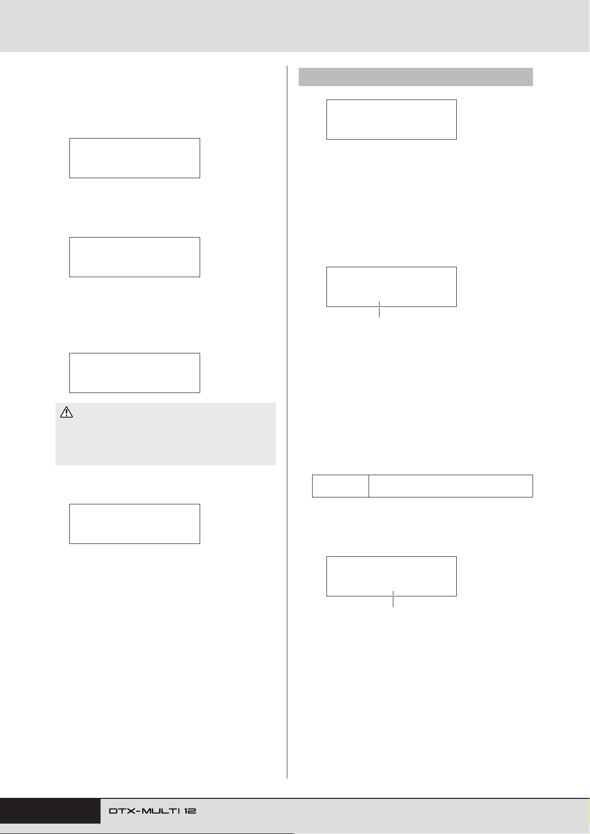
UTILITY Setting Area (UTIL)
When you have set a file name, press the [ENTER]
4
button.
You will be asked to confirm that the data is to be saved. To
proceed, press the [ENTER] button. Alternatively, you can
press the [EXIT] button to return to Step 3 above without saving.
UTIL7-2 Load File page
UTIL7-2≥≥≥<FILE>
≥≥≥Load≥File
≥≥≥Save≥File
≥Are≥you≥sure?
If a file of the same name already exists, you will be asked to
confirm whether it is to be overwritten as shown below. If you
want to set a different file name to avoid overwriting, press the
[EXIT] button to return to the Name page (UTIL7-1-2).
≥≥≥Save≥File
≥≥≥Overwrite?
Press the [ENTER] button to save the file.
5
The following message will be displayed as the data is being
saved. If you press the [EXIT] button at this time, the save
process will be aborted and the display will return to the
Name page (UTIL7-1-2).
≥Now≥saving...
[EXIT]≥to≥cancel
CAUTION
• Do not unplug the USB memory device from the USB TO
DEVICE port or turn off either the memory device or the DTXMULTI 12 while data is being saved. Failure to observe this precaution can lead to the memory device or the DTX-MULTI 12
being permanently damaged.
When the file has been saved, the display will return to the
Save File page (UTIL7-1).
From the Load File page, you can load files previously saved on a
USB memory device into the DTX-MULTI 12.
Plug the USB memory device containing the
1
required files into the USB TO DEVICE port on the
side of the DTX-MULTI 12.
Navigate to the Load File page (UTIL7-2) and press
2
the [ENTER] button.
The Type page (UTIL7-2-1) will open.
UTIL7-2-1≥<FILE>
Type=All
File type
The Type parameter specifies the types of file to be loaded.
• All ...............All user data – i.e., all User kits, all waves, all
User patterns, all User triggers, and utility settings.
• AllKit ..........All User-kit data
• Kit ...............A single User kit
• AllWave....... All wave data
•Wave............ A single wave
• AllPattern .... All User-pattern data
•Pattern .........A single User pattern
• AllTrigger....All User-trigger data
•Trigger......... A single User trigger setup
• Utility .......... Utility settings
Settings
All, AllKit, Kit, AllWave, Wave, AllPattern,
Pattern, AllTrigger, Trigger, or Utility
UTIL7-1≥≥≥<FILE>
≥≥≥Save≥File
Specify a file type using the Type parameter, and
3
press the [ENTER] button.
The File page (UTIL7-2-2) will open.
UTIL7-2-2≥<FILE>
≥File=ALL_DATA
File name
Select the file to be loaded using the [-/DEC] and [+/INC]
buttons. Only those files matching your selection on the Type
page (UTIL7-2-1) will be presented for loading. If you are
loading a single file, you will first of all need to select the All
file that contains it (for example, when loading a single drum
kit, you first select a file saved with the type “AllKit”). It is
not, however, possible to load a single file when an All type
has been selected for loading.
94 Owner’s Manual
Page 95
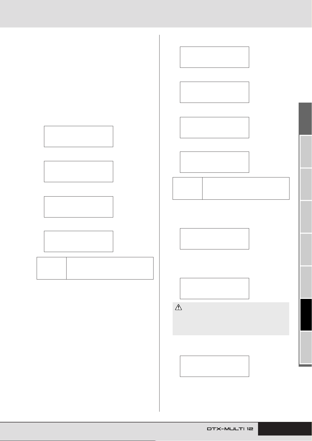
When you have selected the file to be loaded, press
UTIL7-2-4≥≥<Dst>
U001:User≥Kit
UTIL7-2-4≥≥<Dst>
WV001:Empty≥Wave
UTIL7-2-4≥≥<Dst>
©U001:Empty≥Ptn
UTIL7-2-4≥≥<Dst>
U01:User≥Trigger
If “Kit” was selected:
If “Wave” was selected:
If “Pattern” was selected:
If “Trigger” was selected:
≥≥≥Load≥File
≥Are≥you≥sure?
Now≥loading.....
[EXIT]≥to≥cancel
UTIL7-2≥≥≥<FILE>
≥≥≥Load≥File
4
the [ENTER] button.
If “All”, “AllKit”, “AllWave”, “AllPattern”, “AllTrigger”,
or “Utility” was selected:
The applicable page from Step 8 below will be displayed.
If “Kit”, “Wave”, “Pattern”, or “Trigger” was selected:
The applicable page from Step 5 below will be displayed.
Select the required package of data from inside the
5
selected file.
You can scroll through the available data using the [-/DEC]
and [+/INC] buttons.
If “Kit” was selected:
UTIL7-2-3≥≥<Src>
U001:MyKit
If “Wave” was selected:
UTIL7-2-3≥≥<Src>
WV001:MyWave
If “Pattern” was selected:
UTIL7-2-3≥≥<Src>
©U001:MyPtn
If “Trigger” was selected:
UTILITY Setting Area (UTIL)
Kit: U001 to U200
Settings
When you have selected the file to be loaded, press
8
the [ENTER] button.
You will be asked to confirm that the data is to be loaded.
Wave: WV001 to WV500
Pattern: eU001 to eU050
Tr igger: U01 to U10
Settings
When you have selected the file to be loaded, press
6
the [ENTER] button.
Select a destination for the data to be loaded.
7
The [-/DEC] and [+/INC] buttons can be used to select the
number of the User kit, wave, User pattern, or User trigger to
be overwritten with the loaded data.
UTIL7-2-3≥≥<Src>
U01:MyTrigger
Kit: U001 to U200
Wave: WV001 to WV500
Pattern: eU001 to eU050
Tr igger: U01 to U10
To proceed, press the [ENTER] button.
9
The following message will be displayed as the data is being
loaded.
CAUTION
• Do not unplug the USB memory device from the USB TO
DEVICE port or turn off either the memory device or the DTXMULTI 12 while data is being loaded. Failure to observe this
precaution can lead to the memory device or the DTX-MULTI 12
being permanently damaged.
When the data has been loaded, the display will return to the
Load File page (UTIL7-2).
TRIGGER ReferenceKITMIDI VOICEUTILITY WAVEPATTERN
Owner’s Manual 95
Page 96
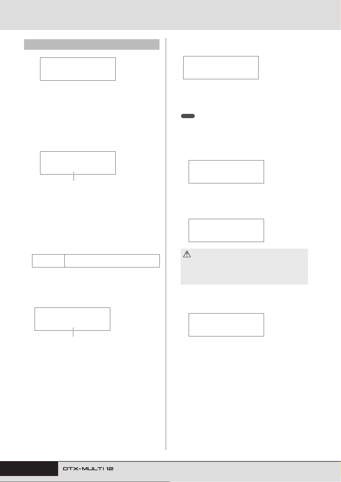
UTILITY Setting Area (UTIL)
UTIL7-3 Rename File page
Press the [ENTER] button to open the Rename To
4
page (UTIL7-3-3).
UTIL7-3≥≥≥<FILE>
≥≥Rename≥File
From the Rename File page, you can rename files that have been
saved on a USB memory device.
Plug the USB memory device into the USB TO
1
DEVICE port on the side of the DTX-MULTI 12.
Navigate to the Rename File page (UTIL7-3) and
2
press the [ENTER] button to open the Type page
(UTIL7-3-1).
UTIL7-3-1≥<FILE>
Type=All
File type
Use the Type parameter to indicate the type of file to be
renamed.
• All................All user data – i.e., all User kits, all User
waves, all User patterns, all User triggers, and
utility settings.
• AllKit...........All User-kit data
• AllWave .......All wave data
• AllPattern ....All User-pattern data
• AllTrigger....All User-trigger data
• Utility ..........Utility settings
Settings
Press the [ENTER] button to open the Rename From
3
page (UTIL7-3-2).
Select the file to be renamed using the [-/DEC] and [+/INC]
buttons.
All, AllKit, AllWave, AllPattern, AllTrigger, or
Utility
UTIL7-3-3≥≥≥<To>
Name=[MYDATA]
The [B]/[C] buttons can be used to move the flashing cur-
sor, and the [-/DEC] and [+/INC] buttons can be used to scroll
through the available characters. File names can be up to eight
characters long.
NOTE
•Any space characters included in file names will be automatically
replaced with “_” (i.e., an underscore).
When you have set the new file name, press the
5
[ENTER] button.
You will be asked to confirm that the file is to be renamed.
≥≥Rename≥File
≥Are≥you≥sure?
Press the [ENTER] button to rename the file.
6
The following message will be displayed as the file is being
renamed.
Executing...
CAUTION
• Do not unplug the USB memory device from the USB TO
DEVICE port or turn off either the memory device or the DTXMULTI 12 while data is being renamed. Failure to observe this
precaution can lead to the memory device or the DTX-MULTI 12
being permanently damaged.
When the renaming process has been completed, the message
“Completed.” will be displayed. Following this, the display
will return to the Rename File page (UTIL7-3).
UTIL7-3-2≥<From>
≥File=ALL_DATA
File name
Only those files matching your selection on the Type page
(UTIL7-3-1) will be presented for renaming.
96 Owner’s Manual
UTIL7-3≥≥≥<FILE>
≥≥Rename≥File
Page 97
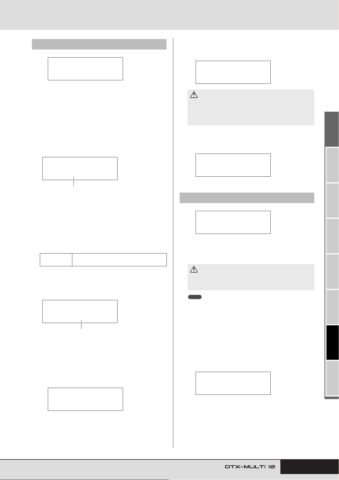
UTIL7-4 Delete File page
Executing...
UTIL7-4≥≥≥<FILE>
≥≥Delete≥File
UTIL7-5≥≥≥<FILE>
≥≥≥≥≥Format
≥≥≥≥Format
≥Are≥you≥sure?
UTIL7-4≥≥≥<FILE>
≥≥Delete≥File
UTILITY Setting Area (UTIL)
To proceed, press the [ENTER] button.
5
The following message will be displayed as the data is being
deleted.
From the Delete File page, you can delete files that have been
saved on a USB memory device.
Plug the USB memory device containing the file(s)
1
you want to delete into the USB TO DEVICE port on
the side of the DTX-MULTI 12.
Navigate to the Delete File page (UTIL7-4) and press
2
the [ENTER] button.
The Type page (UTIL7-4-1) will open.
UTIL7-4-1≥<FILE>
Type=All
File type
The Type parameter specifies the types of file to be deleted.
• All ...............All user data – i.e., all User kits, all waves, all
User patterns, all User triggers, and utility settings.
• AllKit ..........All User-kit data
• AllWave....... All wave data
• AllPattern .... All User-pattern data
• AllTrigger....All User-trigger data
• Utility .......... Utility settings
Settings
Specify a file type using the Type parameter, and
3
press the [ENTER] button.
The File page (UTIL7-4-2) will open.
All, AllKit, AllWave, AllPattern, AllTrigger, or
Utility
UTIL7-4-2≥<FILE>
≥File=ALL_DATA
File name
CAUTION
• Do not unplug the USB memory device from the USB TO
DEVICE port or turn off either the memory device or the DTXMULTI 12 while data is being deleted. Failure to observe this
precaution can lead to the memory device or the DTX-MULTI 12
being permanently damaged.
When the deletion process has been completed, the message
“Completed.” will be displayed. Following this, the display
will return to the Delete File page (UTIL7-4).
UTIL7-5
Certain types of USB memory device must be formatted before
they can be used with your DTX-MULTI 12. The correct way to
format such a device is as follows.
• In certain cases, USB memory devices formatted on a computer will
Plug the USB memory device into the USB TO
1
DEVICE port on the side of the DTX-MULTI 12.
Format page
CAUTION
• All data on the USB memory device will be deleted during the
formatting process. Before formatting a memory device, therefore, ensure that any important data it contains is backed up.
NOTE
not be recognized by the DTX-MULTI 12. Be sure, therefore, to always
use this instrument to format memory devices that will be used with it.
Select the file to be deleted using the [-/DEC] and [+/INC]
buttons. Only those files matching your selection on the Type
page (UTIL7-4-1) will be available for selection.
When you have selected the file to be deleted, press
4
the [ENTER] button.
You will be asked to confirm that the file is to be deleted.
≥≥Delete≥File
≥Are≥you≥sure?
Navigate to the Format page (UTIL7-5) and press the
2
[ENTER] button.
You will be asked to confirm that the USB memory device is
to be formatted.
Owner’s Manual 97
TRIGGER ReferenceKITMIDI VOICEUTILITY WAVEPATTERN
Page 98
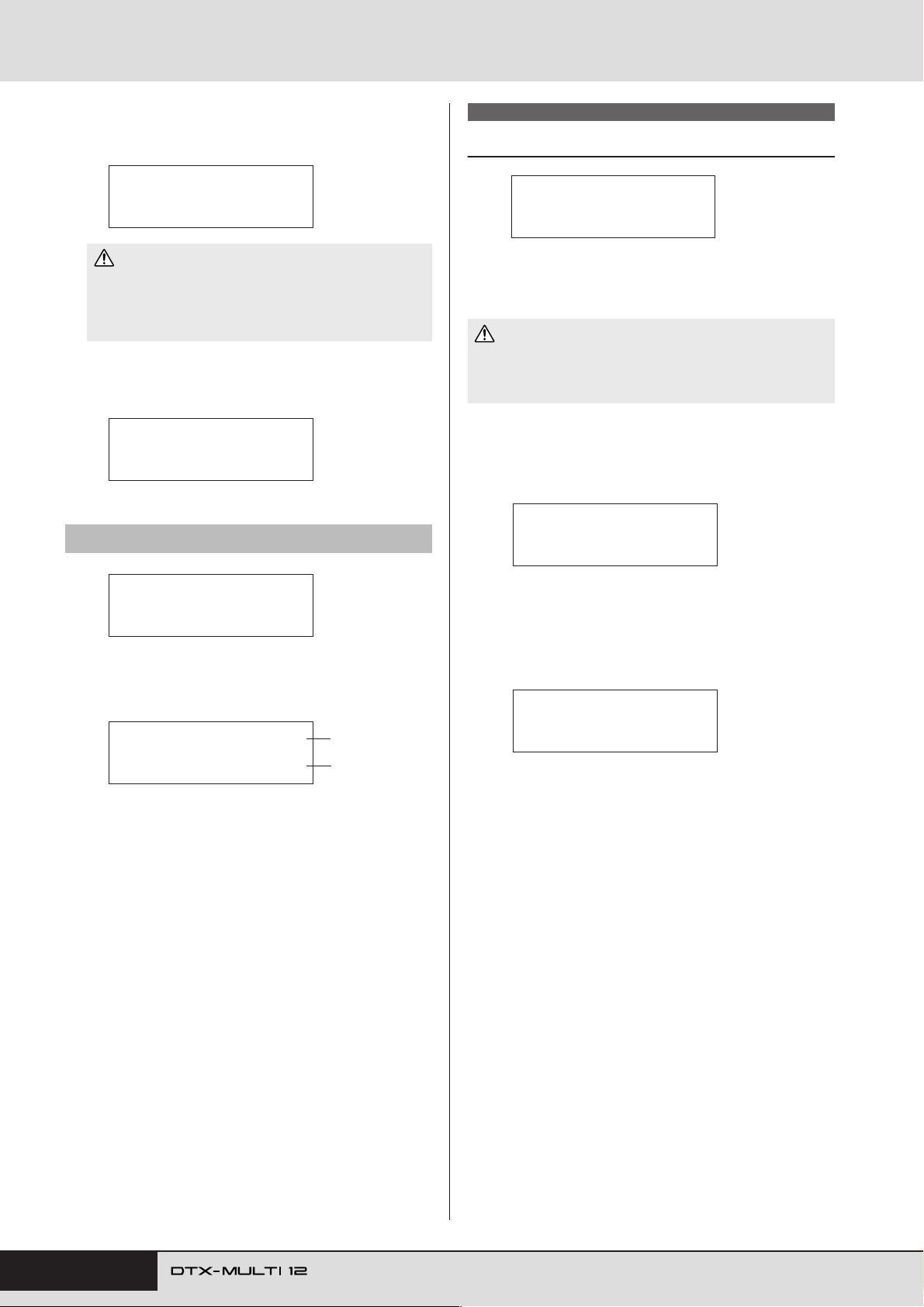
UTILITY Setting Area (UTIL)
To proceed, press the [ENTER] button.
3
The following message will be displayed as the memory
device is being formatted.
Executing...
CAUTION
• When formatting a USB memory device, it must not be
unplugged from the USB TO DEVICE port and the memory
device and the DTX-MULTI 12 must not be turned off. Failure to
observe this precaution can lead to the memory device or the
DTX-MULTI 12 being permanently damaged.
When the formatting process has been completed, the message “Completed.” will be displayed. Following this, the display will return to the Format page (UTIL7-5).
UTIL7-5≥≥≥<FILE>
≥≥≥≥≥Format
UTIL7-6 Memory Info page
UTIL8 FACTORY SET
Instrument Reset
UTIL8
≥≥FACTORY≥SET
In the FACTORY SET section, you can restore all of the DTXMULTI 12’s user data (i.e., all User kits, waves, User patterns,
User triggers, and utility parameters) to default settings.
CAUTION
• Whenever the instrument is reset in this way, any settings you have
made will be overwritten with the corresponding defaults. All important user-defined data should, therefore, be saved on a USB memory device (see page 93) in advance.
Navigate to the Factory Set page (UTIL8) and
1
press the [ENTER] button.
You will be asked to confirm that a Factory Set operation is to
be performed.
≥≥Factory≥Set
≥Are≥you≥sure?
UTIL7-6≥≥≥<FILE>
≥≥Memory≥Info
From the Memory Info page, you can check the memory-usage
status of a USB memory device. To do so, navigate to the Memory Info page (UTIL7-6) and press the [ENTER] button.
UTIL7-6-1≥≥≥6.5%
≥≥≥8.4MB/128.0MB
1 Memory usage ratio (%)
This indicates how much of the USB memory device’s total
memory is currently being used in percentage format.
B Used memory / Total memory
This indicates separately the amount of memory used and the
total memory. The units used here will depend on the corresponding memory size (i.e., KB for kilobytes, MB for megabytes, and GB for gigabytes).
1
2
To proceed, press the [ENTER] button. Alterna-
2
tively, you can press the [EXIT] button to cancel
the process.
The messages “Executing...” and “Please keep power on.” will
be displayed during the Factory Set process.
Executing...
When the process has been completed, the message “Completed.” will be displayed. Following this, the display will
return to the Factory Set page (UTIL8).
98 Owner’s Manual
Page 99
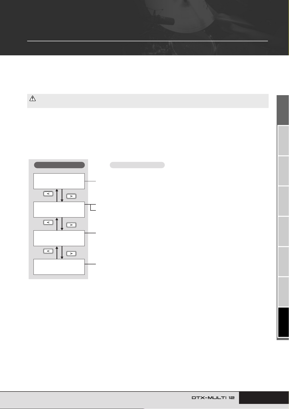
TRIGGER Setting Area (TRG)
This section describes the TRIGGER setting area, which can be accessed by pressing the [SHIFT] and [UTILITY] buttons simultaneously. The characteristics of the trigger signals output from pads when they are played depend on a
range of different factors, such as whether sticks or hands are used, and in the case of external pads, the design of the
pads themselves. The TRIGGER setting area allows you to optimize each pad’s trigger signals for processing by the
DTX-MULTI 12 and to save these settings as trigger setup data.
CAUTION
• Be sure to store any settings that you have edited before turning off the instrument or selecting a new trigger setup. (See page 45.)
Makeup of TRIGGER Setting Area
The TRIGGER setting area is subdivided into four different sections (TRG1 to TRG4). Use the [B]/[C] buttons to navigate between
these sections. If a section contains parameter-setting pages, the [ENTER] button will light up. Press the [ENTER] button to access these
pages. In certain cases, a number of additional pages may be accessed from a parameter setting page, also using the lit [ENTER] button.
Furthermore, you can press the [EXIT] button to move back towards the top of the setting area.
Sections
TRG1≥≥≥≥≥≥≥≥≥≥˛¸
P1:Stick≥Wide
TRG2≥≥≥≥≥≥≥≥≥≥˛¸
≥≥≥≥≥≥PAD
TRG3
≥≥≥≥≥≥NAME
TRG4
≥≥≥≥COPY≥PAD
Parameter-setting pages
TRG1 Select Trigger Setup ...........................................................................Page 100
TRG2-1 Pad Type page................................................................................. Page 100
TRG2-2 Crosstalk Prevention page .............................................................. Page 102
TRG3-1 Trigger Setup Name page ............................................................... Page 104
TRG4-1 Trigger Setup Copy page................................................................. Page 104
Owner’s Manual 99
TRIGGER ReferenceKITMIDI VOICEUTILITY WAVEPATTERN
Page 100
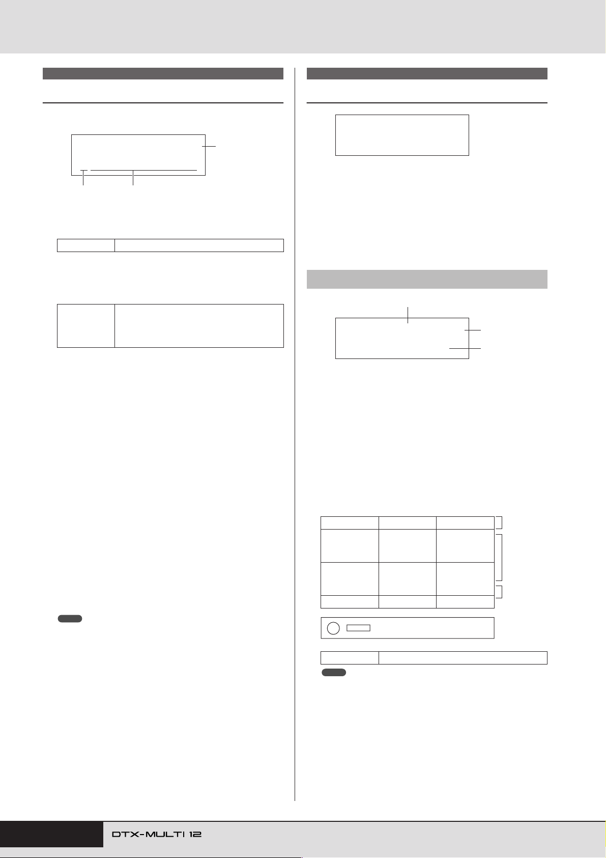
TRIGGER Setting Area (TRG)
TRG1
Select Trigger Setup
Use these parameters to select the trigger setup that you want to
apply or edit.
TRG1≥≥≥≥≥≥≥≥≥≥˛¸
P01:Stick≥Wide
1
A Trigger setup category
Use this parameter to specify either the Preset (P) or User (U)
trigger-setup category.
Settings P or U
B Trigger setup number: Trigger setup name
Use these parameters to select the trigger setup that you want
to apply or edit.
Settings
P01: Stick Wide ......... Stick-playing trigger setup with a wide
P02: Stick Normal...... Stick-playing trigger setup with a stan-
P03: Stick Narrow...... Stick-playing trigger setup with a nar-
P04: Hand .................. Hand-playing trigger setup.
P05:Finger.................. Hand-playing trigger setup that also
U01 to U10 ................ User triggers.
C Input level indicator
Visual representation of the input level for the pad(s) being
struck.
NOTE
• The Trigger Setup Link page (KIT7-6) can be used to set a complete
trigger setup for the current kit. (See page 52)
2
With “P” (Preset trigger setup) selected:
01 to 05
With “U” (User trigger setup) selected:
01 to 10
dynamic range, allowing the softness
or hardness of playing to be easily
expressed.
dard, well-balanced response.
row dynamic range for highly-consistent hit detection. With this setup, the
softness or hardness of playing has less
effect, allowing differences in volume
to be smoothed out.
supports finger-tip playing.
Freely-configurable trigger setups for
your own unique triggering needs.
3
TRG2 PAD
Pad Setup
TRG2≥≥≥≥≥≥≥≥≥≥˛¸
≥≥≥≥≥≥PAD
In the PAD section, you can set parameters affecting the sensitivity, output, and other characteristics of each of your DTX-MULTI
12’s built-in pads and of external pads connected via the PAD
jacks. With the PAD page (TRG2) displayed, press the [ENTER]
button to access the Pad Type (TRG2-1) and Crosstalk Prevention
(TRG2-2) parameter-setting pages. You can use the [B]/[C]
buttons to switch between these pages.
TRG2-1 Pad Type page
1
TRG2-1≥-MID-≥≥˛¸
Type=StickDyna
1 Pad
Use this parameter to select the pad(s) to be set.
UPUpper row of built-in rim pads (i.e., 1 to 3)
MIDMiddle rows of built-in pads (i.e., 4 to 9)
LOWLower row of built-in rim pads (i.e., 10 to 12)
01Built-in pad 1
: :
12Built-in pad 12
13External pad connected to PAD M jack
: :
17External pad connected to PAD Q jack
Layout of built-in pads
01 02 03 UP
04 05 06
07 08 09
10 11 12 LOW
Front panel
3
2
MID
100 Owner’s Manual
Settings UP, MID, LOW, or 01 to 17
NOTE
• Selection by striking is limited to pad groups (i.e., UP, MID, or LOW)
and the external pads (i.e., 13 to 17).
 Loading...