

Page 1

DSP-E800
AV PROCESSOR/AMPLIFIER
AMPLIFICATEUR D’EFFETS AUDIO-VIDEO
BG
OWNER’S MANUAL
MODE D’EMPLOI
BEDIENUNGSANLEITUNG
BRUKSANVISNING
MANUALE DI ISTRUZIONI
MANUAL DE INSTRUCCIONES
GEBRUIKSAANWIJZING
Page 2

CAUTION: READ THIS BEFORE OPERATING YOUR UNIT.
1. To assure the finest performance, please read this
manual carefully. Keep it in a safe place for future
reference.
2. Install this unit in a cool, dry, clean place — away
from windows, heat sources, sources of excessive
vibration, dust, moisture and cold. Avoid sources of
humming (transformers, motors). To prevent fire or
electrical shock, do not expose the unit to rain or
water.
3. Never open the cabinet. If something drops into the
unit, contact your dealer.
4. Do not use force on switches, controls or connection
wires. When moving the unit, first disconnect the
power cord and then the wires connected to other
component. Never pull the wires themselves.
5. The openings on the cover assure proper ventilation
of the unit. If these openings are obstructed, the
temperature inside the unit will rise rapidly.
Therefore, avoid placing objects against these
openings, and install the unit in a well-ventilated area
to prevent fire and damage.
Be sure to allow a space of at least 20 cm behind,
20 cm on both sides and 30 cm above the top panel
of the unit to prevent fire and damage.
6. The voltage used must be the same as that specified
on this unit. Using this unit with a higher voltage than
specified is dangerous and may result in fire or other
accidents. YAMAHA will not be held responsible for
any damage resulting from the use of this unit with a
voltage other than that specified.
7. Digital signals generated by this unit may interfere
with other component such as tuners, receivers and
TVs. Move this unit farther away from such
component if interference is observed.
8. Always set VOLUME to the “m” position before
starting the audio source play. Increase the volume
gradually to an appropriate level after playback has
been started.
9. Do not attempt to clean the unit with chemical
solvents; this might damage the finish. Use a clean,
dry cloth.
10. Be sure to read the “TROUBLESHOOTING” section
regarding common operating errors before
concluding that the unit is faulty.
11. When not planning to use this unit for a long period
of time (e.g., a vacation), disconnect the AC power
cord from the wall outlet.
12. To prevent lightning damage, disconnect the AC
power cord when there is an electrical storm.
13. Grounding or polarization — Precautions should be
taken so that the grounding or polarization of the unit
is not defeated.
14. AC outlet — Do not connect audio component to the
AC outlet on the rear panel if that component
requires more power than the outlet is rated to
provide.
This unit is not disconnected from the AC power source
as long as it is connected to the wall outlet, even if this
unit itself is turned off. This state is called the standby
mode. In this state, this unit is designed to consume a
very small quantity of power.
■ For U.K. customers
If the socket outlets in the home are not suitable for the plug
supplied with this appliance, it should be cut off and an
appropriate 3 pin plug fitted. For details, refer to the
instructions described below.
Note
• The plug severed from the mains lead must be destroyed, as a
plug with bared flexible cord is hazardous if engaged in a live
socket outlet.
■ Special Instructions for U.K. Model
IMPORTANT
THE WIRES IN MAINS LEAD ARE COLOURED IN
ACCORDANCE WITH THE FOLLOWING CODE:
Blue: NEUTRAL
Brown: LIVE
As the colours of the wires in the mains lead of this
apparatus may not correspond with the coloured
markings identifying the terminals in your plug, proceed
as follows:
The wire which is coloured BLUE must be connected to
the terminal which is marked with the letter N or
coloured BLACK. The wire which is coloured BROWN
must be connected to the terminal which is marked with
the letter L or coloured RED.
Making sure that neither core is connected to the earth
terminal of the three pin plug.
CAUTION
Page 3

INTRODUCTION
FEATURES
The DSP-E800 makes it possible for you to enjoy advanced
surround sound with a 5.1 channel system by connecting it
to your present main amplifier.
Built-in 3-Channel Power Amplification
◆ Minimum RMS Output
(0.06% THD, 20 Hz – 20 kHz)
Center: 70 W (8 Ω)
Rear: 70 W + 70 W (8 Ω)
Multi-Mode Digital Sound Field
Processing
◆ Digital Sound Field Processor (DSP)
◆ Dolby Pro Logic Decoder
◆ Dolby Digital Decoder
◆ DTS Decoder
◆ CINEMA DSP: Combination of YAMAHA DSP
Technology and Dolby Pro Logic, Dolby Digital or
DTS
Other Features
◆ 96-kHz/24-bit D/A Converter
◆ “SET MENU” which Provides You with 12 Items
for Optimizing This Unit for Your Audio/Video
System
◆ Test Tone Generator for Easier Speaker Balance
Adjustment
◆ 6-Channel External Decoder Input for Other Future
Formats
◆ S Video Signal Input/Output Capability
◆ 3 Optical/2 Coaxial Digital Signal Input Terminals
◆ SLEEP T imer
◆ Remote Control
CONTENTS
INTRODUCTION
FEATURES .................................................................. 1
CONTENTS ................................................................. 1
GETTING STARTED ................................................. 2
CONTROLS AND FUNCTIONS ............................... 4
PREP ARATION
SPEAKER SETUP.......................................................7
CONNECTIONS..........................................................8
ADJUSTING THE SPEAKER BALANCE ............ 14
BASIC OPERATION
PLA YING A SOURCE .............................................. 16
DIGITAL SOUND FIELD PROCESSOR (DSP)
EFFECT .................................................................. 20
RECORDING A SOURCE ON TAPE, MD OR
VIDEO CASSETTE ............................................... 21
ADVANCED OPERATION
SOUND FIELD PROGRAM .................................... 22
SET MENU................................................................. 25
DELAY TIME AND SPEAKER
OUTPUT LEVELS ................................................. 29
SLEEP TIMER .......................................................... 31
INTRODUCTION PREP ARA TION
ADV ANCED OPERA
TION APPENDIX
Manufactured under license from Dolby
Laboratories. “Dolby”, “Pro Logic” and the
double-D symbol are trademarks of Dolby
Laboratories. Confidential Unpublished Works.
©1992 – 1997 Dolby Laboratories, Inc. All
rights reserved.
Manufactured under license from Digital Theater Systems,
Inc. US Pat. No. 5,451,942 and other world-wide patents
issued and pending. “DTS”, “DTS Digital Surround”, are
trademarks of Digital Theater Systems, Inc. Copyright 1996
Digital Theater Systems, Inc. All Rights Reserved.
APPENDIX
TROUBLESHOOTING ............................................ 32
SPECIFICATIONS.................................................... 35
y indicates a tip for your operation.
• When buttons on this unit and the remote control are
noted together in this Owner’s Manual, these button
names are in principle noted in the order of “button name
(remote control button name)”.
EnglishBASIC OPERATION
E-1
Page 4
GETTING STARTED
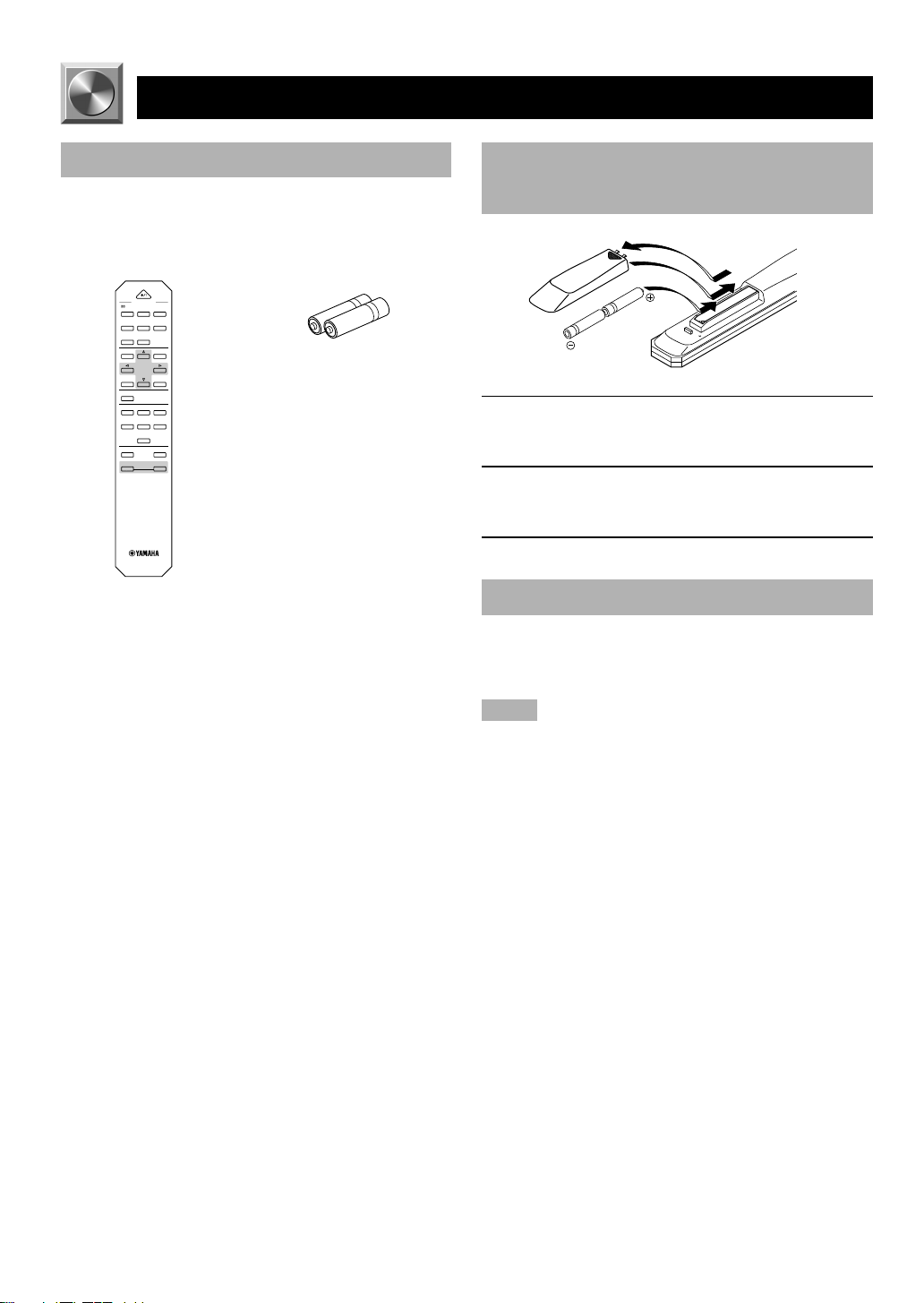
Checking the Package Contents
Check that the following items are included in your
package.
Remote control Batteries (R6 type)
POWER
PROGRAM
/DTS
MOVIE
MOVIE
SUR.
THTR 1
THTR 2
21
3
MONO MOVIE
TV SPORTS
DISCO
4
5
6
ROCK
HALL
7
8
TEST
EFFECT
DSP
TIME/LEVEL
SET MENU
6CH INPUT
CD TUNER TAPE/MD
DVD/LD D–TV VCR
CBL/SAT
SLEEP MUTING
+
–
VOLUME
Battery Installation in the Remote
Control
1
3
2
1 Turn the remote control over and slide the
battery compartment cover in the direction of
the arrow.
2 Insert the batteries (R6 type) according the
polarity markings on the inside of the battery
compartment.
3 Close the battery compartment cover.
Battery Replacement
If the remote control operates only when it is close to the
unit, the batteries are weak. Replace all the batteries with
new ones.
Notes
• Use only R6 batteries for replacement.
• Be sure the battery polarity is correct. (See the illustration inside
the battery compartment.)
• Remove the batteries if the remote control will not be used for an
extended period of time.
• If the batteries have leaked, dispose of them immediately. Avoid
touching the leaked material or letting it come into contact with
clothing, etc. Clean the battery compartment thoroughly before
installing new batteries.
E-2
Page 5

Using the Remote Control
DIGITAL
DOLBY
NATURAL SOUND AV PROCESSOR/AMPLIFIER DSP–E800
STANDBY/ON
+–
Remote control
sensor
The remote control transmits a directional infrared beam. Be
sure to aim the remote control directly at the infrared sensor
during operation. When the sensor is covered or there is a
large object between the remote control and the sensor, the
sensor cannot receive signals. The sensor may not be able to
receive signals properly when it is exposed to direct sunlight
or a strong artificial light (such as a fluorescent or strobe
light). In this case, change the direction of the light or
reposition the unit to avoid direct lighting.
Notes
• Handle the remote control with care.
• Do not spill water, tea or other liquids on the remote control.
• Do not drop the remote control.
• Do not leave or store the remote control in the following
conditions:
– high humidity or temperature such as near a heater, stove or
bath;
– dusty places; or
– extremely low temperature.
CINEMA DSP
DIGITAL
SURROUND
INPUT SELECTOR
INPUT MODE
NEXT
PROGRAMSET MENU EFFECTTAPE/MD MON
/6CH INPUT
Within approximately 6 m
(20 feet)
VOLUME
16
12
20
8
28
4
40
2
60
00 0
–dB
GETTING STARTED
INTRODUCTION PREP ARA TION
ADV ANCED OPERA
E-3
TION APPENDIX
EnglishBASIC OPERATION
Page 6

Front Panel
CONTROLS AND FUNCTIONS
12
NATURAL SOUND AV PROCESSOR/AMPLIFIER DSP–E800
STANDBY/ON
NEXT
+–
3
EFFECTTAPE/MD MON
/6CH INPUT
0987
1 STANDBY/ON
Press this switch to turn on the power of this unit or to set
this unit in the standby mode. Before turning the power on,
set VOLUME to the “m” position.
Standby mode
In this mode, this unit consumes a very small quantity of
power to receive infrared-signals from the remote
control.
2 Remote control sensor
This receives signals from the remote control.
3 Display
This shows various information. (Refer to page 5 for
details.)
4 INPUT MODE
Press this button to select the input mode among AUTO,
DTS and ANALOG for the DVD/LD, D-TV and CBL/SAT
sources.
5 INPUT SELECTOR
Turn this selector to select the input source (TUNER, CD,
VCR, CBL/SAT, D-TV, DVD/LD) that you want to listen to
or watch. The arrow for the selected input source indicator
lights up on the display.
6 VOLUME
Turn this control to turn up or down the volume.
56
VOLUME
20
28
40
60
00 0
CINEMA DSP
DOLBY
DIGITAL
PROGRAMSET MENU
DIGITAL
SURROUND
4
INPUT SELECTOR
INPUT MODE
q
7 SET MENU +/–
Press these buttons to adjust the setting on the SET MENU.
8 NEXT
Press this button to select the item on the SET MENU. This
button functions like
the SET MENU.
9 TAPE/MD MON / 6CH INPUT
Press this button to select a tape or an MD source. The
“TAPE/MD MONITOR” indicator lights up on the display.
When you press the button again, the “TAPE/MD
MONITOR” indicator goes off, “6CH INPUT” appears on
the display and you can listen to a source connected to the
6CH INPUT terminals.
0 EFFECT
Press this button to turn on or off the effect speakers (center
and rear). If you turn them off, the signals of the center and
rear channels are directed to the right and left main speakers
when playing a source encoded with Dolby Digital and
DTS. In this case, the output levels of the right and left
speakers may not match.
q PROGRAM selector
Press l or h to select a DSP program when the effect
speakers (center and rear) are turned on. The name of the
selected program appears on the display.
on the remote control when using
16
12
8
4
2
–dB
E-4
Page 7

Display
CONTROLS AND FUNCTIONS
2
76
5
1
DIGITAL
PRO LOGIC
DSP
ENHANCED MOVIE THEATER 12
1 t indicator
The “t” indicator lights up when the built-in DTS
decoder is on.
2 Multi-information display
This display shows various information: for example the
name of the selected DSP program and the various settings
during adjustment with the SET MENU.
3 Input source indicators
One of the arrows for these indicators lights up depending
on which source is selected.
4 TAPE/MD MONITOR indicator
This lights up when the tape deck or MD recorder, etc. is
selected as the input source by pressing TAPE/MD MON /
6CH INPUT (or TAPE/MD).
TUNER
CD
CBL/SAT
TAPE/MD
MONITOR
SLEEP
4
3
DVD/LD
dB
ms
D–TV
VCR
8
5 g and o indicators
“ g ” lights up when the built-in Dolby Digital
decoder is on. “ o ” lights up when the built-in
Dolby Pro Logic decoder is on.
6 x indicator
“ x ” lights up when the built-in digital sound
field processor is on.
7 DSP program indicators
These indicators light up when DSP program No. 2, 3 or the
subprogram “ENHANCED” of No. 1 is selected.
8 SLEEP indicator
This lights up while the built-in SLEEP timer is on.
INTRODUCTION PREP ARA TION
ADV ANCED OPERA
E-5
TION APPENDIX
EnglishBASIC OPERATION
Page 8

CONTROLS AND FUNCTIONS
Remote Control
POWER
1
2
3
4
5
6
PROGRAM
/DTS
MOVIE
SUR.
THTR 1
21
MONO MOVIE
TV SPORTS
4
5
ROCK
HALL
7
8
TEST
DSP
TIME/LEVEL
6CH INPUT
CD TUNER TAPE/MD
DVD/LD D–TV VCR
CBL/SAT
SLEEP MUTING
–
VOLUME
MOVIE
THTR 2
3
DISCO
6
EFFECT
SET MENU
5 6CH INPUT
Press this button to select the source connected to the 6CH
INPUT terminals.
7
6 SLEEP
Press this button to set the SLEEP timer.
7 PROGRAM selector buttons
These buttons select a DSP program.
8
9
8 EFFECT
Press this button to turn on or off the effect speakers (center
and rear).
0
9 (next), (back)
These buttons are used to advance or go back one selection
on the SET MENU and TIME/LEVEL mode.
q
0 SET MENU
Press this button to select the items on the SET MENU.
+
w
e
q Input selector buttons
These buttons select the input source.
CD: To play a CD
TUNER: To listen to an FM or AM broadcast
TAPE/MD: To play a tape or MD
DVD/LD: To play a DVD or LD
D-TV: To watch a TV
VCR: To play a video cassette
CBL/SAT: To watch cable TV or satellite broadcast
1 POWER
Each time you press this button, the unit switches between
the power on and standby mode.
2 TEST
Press this button to output the test tone for each speaker.
3 l (left), h (right)
These buttons adjust the setting of the SET MENU and
TIME/LEVEL mode.
4 TIME/LEVEL
Press this button to select the items in the TIME/LEVEL
mode.
w MUTING
Press this button to mute the sound. To cancel mute, press
this button again.
e VOLUME +/–
These buttons are used to adjust the volume level.
+: To turn up the volume
–: To turn down the volume
E-6
Page 9
PREP ARA TION
SPEAKER SETUP
Speakers to Be Used
This unit is designed to provide the best sound-field quality
with a 5-speaker system, using main speakers, rear speakers
and a center speaker. If you use different brands of speakers
(with different tonal qualities) in your system, the tone of a
moving human voice and other types of sound may not shift
smoothly. We recommend that you use speakers from the
same manufacture or speakers with the same tonal quality.
The main speakers are used for the main source sound plus
the effect sounds. They will probably be the speakers from
your present stereo system. The rear speakers are used for
the effect and surround sounds, and the center speaker is for
the center sounds (dialog, vocals, etc.). If for some reason it
is not practical to use a center speaker, you can do without
it. Best results, however, are obtained with the full system.
The main speakers should be high-performance models and
have enough power-handling capacity to accept the
maximum output of your audio system. The other speakers
do not have to be equal to the main speakers. For precise
sound localization, however, it is ideal to use highperformance models that can reproduce sounds over the full
range for the center speaker and the rear speakers.
■ Use of a subwoofer expands your
sound field
It is also possible to further expand your system with the
addition of a subwoofer. The use of a subwoofer is effective
not only for reinforcing bass frequencies from any or all
channels, but also for reproducing the LFE (low frequency
effect) channel with high fidelity when playing back a
source encoded with Dolby Digital or DTS. The YAMAHA
Active Servo Processing Subwoofer System is ideal for
natural and lively bass reproduction.
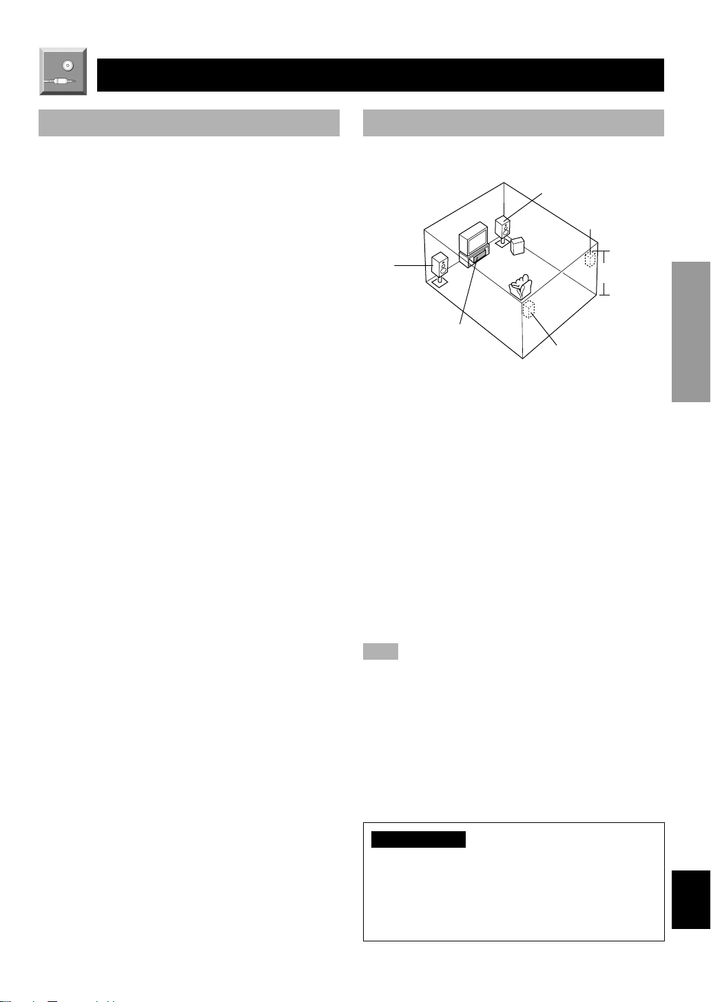
Speaker Placement
Refer to the following diagram when you place the
speakers.
Main speaker (R)
Rear speaker (R)
Subwoofer
Main
speaker (L)
Center speaker
Rear speaker (L)
■ Main speakers
Place the right and left main speakers an equal distance
from the ideal listening position. The distance of each
speaker from each side of the TV monitor should be the
same.
■ Rear speakers
Place these speakers behind your listening position, facing
slightly inwards, nearly 1.8 m (approx. 6 feet) above the
floor.
■ Center speaker
Align the front face of the center speaker with the front face
of your TV monitor. Place the speaker as close to the
monitor as possible, such as directly over or under the
monitor and centrally between the main speakers.
Note
• If the center speaker is not used, the center channel sound will be
heard from the right and left main speakers. In that case,
“CENTER SP” on the SET MENU is set to the NONE position.
(Refer to page 26 for details.)
1.8 m
INTRODUCTION
PREP ARA TION
ADV ANCED OPERA
TION APPENDIX
■ Subwoofer
The position of the subwoofer is not so critical, because low
bass sounds are not highly directional. But it is better to
place the subwoofer near the main speakers. Turn it slightly
toward the center of the room to reduce the wall reflections.
CAUTION
Some types of speakers interfere with a TV monitor. If
this problem occurs, move the speakers away from the
monitor. If you cannot avoid installing the center speaker
or subwoofer near the TV monitor, use magnetically
shielded speakers.
E-7
EnglishBASIC OPERATION
Page 10

CONNECTIONS
L
R
L
R
C C
V V
Before Connecting Components
CAUTION
Never connect this unit and other components to mains power until all connections between components have been
completed.
Be sure all connections are made correctly, that is to say L (left) to L, R (right) to R, “+” to “+” and “–” to “–”. Some
components require different connection methods and have different terminal names. Refer to the instructions for each
component to be connected to this unit.
When you connect other YAMAHA audio components (such as a tape deck, MD recorder and CD player or changer), connect
it to the terminals with the same number labels as !, @, #, $ etc. YAMAHA applies this labeling system to all its
products.
Use RCA-type pin plug cables for connecting audio/video components with the exception described later.
The input and output terminals for pin plugs can be distinguished as follows:
Yellow video signals (composite)
White analog audio signals for the left channel
Red analog audio signals for the right channel
coaxial digital signals
After completing all connections, check them again to make sure they are correct.
Connecting to an External
Decoder (page 9)
MAIN
SURROUND
6CH
INPUT
L
EXTERNAL
DECODER
R
MAIN IN
L
R
DVD/LD D–TV CBL/SAT
CENTER
IN (PLAY)
CD TUNER
1 2 3 4
IN OUT MONITOR
VCR
S VIDEO SIGNAL
TAPE/MD
Connecting an Audio
Component (page 9)
Digital signal input
terminals (page 10)
DIGITAL SIGNAL
DVD/LD D–TV CBL/SAT
SUB
WOOFER
AUDIO SIGNAL
OUT (REC)
DVD/LD D–TV CBL/SAT
OUT
DVD/LD
DVD/LD CBL/SAT
OPTICAL COAXIAL
IN
VIDEO SIGNAL
IN
D–TV CBL/SAT
VCR
VCR
Connecting a Video
Component (pages 10 and 11)
Connecting the
Speakers (page 11)
L
R
OUT
OUT MONITOR
OUT
SPEAKERS
CAUTION
SEE INSTRUCTION MANUAL FOR CORRECT SETTING.
CENTER REAR
R
+
–
(SURROUND)
Connecting the External
Amplifier (page 11)
L
MAIN
L
R
IMPEDANCE SELECTOR
WOOFER
SUB
SET BEFORE POWER ON
REAR
: 4ΩMIN./SPEAKER
CENTER
: 4ΩMIN./SPEAKER
REAR
: 8ΩMIN./SPEAKER
CENTER
: 8ΩMIN./SPEAKER
OUTPUT
REAR
(SURROUND)
CENTER
IMPEDANCE SELECTOR
switch (page 13)
(Europe model)
To AC outlet
AC OUTLET
SWITCHED
100W MAX.
Connecting the Power
Supply Cords (page 13)
E-8
Page 11

Connecting an Audio Component
A
CONNECTIONS
CD player
OUTPUT
6CH
INPUT
EXTERNAL
DECODER
DVD/LD D–TV CBL/SAT
L R
L
R
MAIN IN
L
R
OUTPUT
Tuner
MAIN
SURROUND
CENTER
IN (PLAY)
CD TUNER
1 2 3 4
IN OUT MONITOR
VCR
S VIDEO SIGNAL
L R
SUB
WOOFER
AUDIO SIGNAL
OUT (REC)
TAPE/MD
OUT
L R
LINE OUT
L
R
DIGITAL SIGNAL
DVD/LD D–TV CBL/SAT
OPTICAL COAXIAL
DVD/LD D–TV CBL/SAT
D–TV CBL/SAT
DVD/LD
VIDEO SIGNAL
Tape deck or
MD recorder
Analog signal
Signal flow
DVD/LD CBL/SAT
L
R
IN
OUT
VCR
IN
OUT MONITOR
OUT
VCR
L R
LINE IN
Be sure to connect the right channel (R), left channel (L),
input (IN) and output (OUT) properly.
INTRODUCTION
PREP ARA TION
Connecting to an External Decoder
External decoder
MAIN
OUT
L R L R
6CH
INPUT
EXTERNAL
DECODER
MAIN IN
DVD/LD D–TV CBL/SAT
EXTERNAL
DECODER
EXTERNAL DECODER/MAIN IN switch
SURROUND
OUT
MAIN
SURROUND
L
R
L
R
CD TUNER
1 2 3 4
IN OUT MONITOR
S VIDEO SIGNAL
MAIN IN
CENTER
IN (PLAY)
VCR
CENTER
OUT
SUB
WOOFER
AUDIO SIGNAL
OUT (REC)
TAPE/MD
OUT
SUBWOOFER
OUT
DIGITAL SIGNAL
DVD/LD D–TV CBL/SAT
OPTICAL COAXIAL
DVD/LD D–TV CBL/SAT
DVD/LD
D–TV CBL/SAT
VIDEO SIGNAL
DVD/LD CBL/S
IN
VCR
IN
VCR
OUT
OUT
This unit has additional 6-channel audio signal input
terminals for connecting an external decoder to this unit. Set
the EXTERNAL DECODER/MAIN IN switch to the
EXTERNAL DECODER position. Connect the 6-channel
audio signal output terminals of the decoder to the 6CH
INPUT terminals of this unit.
CAUTION
Be sure to move the EXTERNAL DECODER/MAIN IN
switch only when this unit is in the standby mode.
Notes
• When a source connected to these terminals is selected, the digital
sound field processor cannot be used.
• The settings of “CENTER SP”, “REAR SP”, “MAIN SP” and
“BASS OUT” on the SET MENU have no effect on a source
connected to these terminals. The setting of “MAIN LVL” is
effective. (Refer to pages 26 and 27 for details.)
• Adjustment of the output level of the center speaker, rear speakers
and subwoofer is effective when a source connected to these
terminals is selected as the input source. (Refer to page 29 for
details.)
ADV ANCED OPERA
TION APPENDIX
EnglishBASIC OPERATION
E-9
Page 12

R
CONNECTIONS
Connecting a Video Component
DVD/LD player
L R
ANALOG
AUDIO
OUT
MAIN
SURROUND
L
R
IN
L
R
CD TUNER
1 2 3 4
TV/Digital TV
L
Analog signal
R
O
Digital signal
(optical)
DIGITAL SIGNAL
(COAXIAL)
DIGITAL
SIGNAL
(OPTICAL)
CENTER
SUB
WOOFER
AUDIO SIGNAL
IN (PLAY)
OUT (REC)
TAPE/MD
DVD/LD D–TV CBL/SAT
DIGITAL
SIGNAL
(OPTICAL)
ANALOG
AUDIO OUT
C
O
DIGITAL SIGNAL
DVD/LD D–TV CBL/SAT
OPTICAL COAXIAL
O
L R
Cable TV/
satellite tuner
DIGITAL
SIGNAL
(OPTICAL)
O
DVD/LD CBL/SAT
IN
OUT
VCR
C
AUDIO
OUT
VCR
C
Digital signal
(coaxial)
Signal flow
DIGITAL
SIGNAL
(COAXIAL)
ANALOG
AUDIO
L
R
L RL R
OUT
AUDIO
IN
L R
Notes
• Be sure to attach the covers when the OPTICAL terminals are not
being used in order to protect them from dust.
• If your LD player has a Dolby Digital RF signal output terminal,
be sure to use the RF demodulator (separately purchased).
• No sound will be heard when connecting your LD player’s Dolby
Digital RF signal output terminal directly to this unit’s COAXIAL
DVD/LD digital signal input terminal.
y
• The input signal from the DVD/LD or CBL/SAT input terminals
is selected in the following order of priority with the input mode
set to AUTO: COAXIAL terminal → OPTICAL terminal →
Analog terminal. Refer to page 18 for details.
• All digital signal input terminals are applicable to sampling
frequencies of 32 kHz, 44.1 kHz, 48 kHz and 96 kHz. (Refer to
page 19 about 96-kHz sampling 24-bit digital signals.)
■ Video signal terminals (composite)
If your video components do not have “S” video terminals,
they can be connected to this unit’s VIDEO terminals. Be
sure to connect the input (IN) and output (OUT) properly.
TV monitor
VIDEO IN
V
DVD/LD player
VIDEO
OUT
V
TV/Digital TV
VIDEO OUT
V
■ Audio signal terminals
Be sure to connect the right channel (R), left channel (L),
input (IN) and output (OUT) properly.
Note
• Be sure to make the video connections as well.
■ Digital audio signal terminals
If your DVD/LD player, TV/digital TV or cable TV/satellite
tuner, etc. has coaxial or optical digital signal output
terminals, they can be connected to this unit’s COAXIAL
V
Video signal
DVD/LD D–TV CBL/SAT VCR
DVD/LD D–TV CBL/SAT
V
VIDEO
OUT
Cable TV/
satellite tuner
VIDEO SIGNAL
VIDEO
OUT
IN
VCR
OUT MONITOR
OUT
VV
VIDEO
IN
VCR
Signal flow
and/or OPTICAL digital signal input terminals. To make a
connection between the optical digital signal terminals,
remove the cover from each terminal, and then connect
them by using a commercially available optical fiber cable
that conforms to EIA standards. Other cables might not
function correctly.
Notes
• Be sure to make the audio connections as well.
• If video signals are input from both the S VIDEO input and
composite input terminals, the signals will be directed to their
respective output terminals.
When making connections between the digital signal
terminals, you should connect the components to the samenamed analog audio signal terminals of this unit, because a
digital signal cannot be recorded by a tape deck, MD
recorder or VCR connected to this unit.
E-10
Page 13

E
M
M
M
M
1 2 3 4
V
■ S VIDEO terminals
S
S VIDEO
Cable TV/
satellite tuner
IN OUT MONITOR
VCR
S VIDEO SIGNAL
OUT
S VIDEO
OUT
S
OUT
S S
S VIDEO
IN
D
TV/Digital TV
S VIDEO
OUT
DVD/LD D–TV CBL/SAT
S
S VIDEO
OUT
S
TV Monitor
S VIDEO IN
S
S Video signal
Signal flow
CONNECTIONS
If your video components have “S” (high-resolution) video
terminals, they can be connected to this unit’s S VIDEO
terminals. Be sure to connect the input (IN) and output
(OUT) properly.
Notes
• Use a special S VIDEO cable (commercially available) for the S
VIDEO connection.
• If video signals are input from both the S VIDEO input and
composite input terminals, the signals will be directed to their
respective output terminals.
INTRODUCTION
PREP ARA TION
DVD/LD player
VCR
Connecting the Speakers and the External Amplifier
Center speaker
CAUTION
SEE INSTRUCTION MANUAL FOR CORRECT SETTING.
CENTER REAR
+
–
Main speaker
Right
Rear speakers
Right
SPEAKERS
R
(SURROUND)
Left
L
L
R
MAIN
IN
2-ch power amplifier
MAIN
R
OUTPUT
(SURROUND)
L R
REAR
L
Subwoofer
system
CENTER
SUB
WOOFER
Main speaker
IMPEDANC
SET BEFORE
REAR
CENTER
REAR
CENTER
: 4Ω
: 4Ω
: 8Ω
: 8Ω
Left
Basic connection
It is necessary to connect a 2-channel amplifier to this unit
in order to drive main speakers.
Be sure to connect the right channel (R), left channel (L),
“+” (red) and “–” (black) properly. If the connections are
faulty, no sound will be heard from the speakers, and if the
polarity of the speaker connections is incorrect, the sound
will be unnatural and lack bass.
■ Connecting 2-channel amplifier
Connect the input terminals of a 2-ch power amplifier to the
MAIN OUTPUT terminals of this unit. If you connect the
AUX input terminals of the external amplifier to the MAIN
OUTPUT terminals of this unit, be sure to set the volume of
the external amplifier around –16 dB to –18 dB.
■ Connecting a rear speaker system
Connect a rear speaker system to the REAR SPEAKER
(SURROUND) output terminals of this unit.
■ Connecting a center speaker
Connect a center speaker to the CENTER SPEAKER output
terminals of this unit.
ADV ANCED OPERA
TION APPENDIX
CAUTIONS
• Use speakers with the specified impedance shown on
the rear panel of this unit.
• Do not let the bare speaker wires touch each other and
do not let them touch any metal part of this unit. This
could damage the unit and/or speakers.
■ Connecting a subwoofer system
Connect the input terminal of a subwoofer system to the
SUBWOOFER OUTPUT terminal of this unit.
EnglishBASIC OPERATION
E-11
Page 14

CONNECTIONS
■ Speaker cables
10 mm (3/8”)
12
1 Remove approx. 10 mm (3/8”) of insulation
from each of the speaker cables.
2 Twist the exposed wires of the cable together
to prevent short circuits.
■ Connecting to the REAR and
CENTER SPEAKERS terminals
Red: positive (+)
Black: negative (–)
2
1
3
1 Unscrew the knob.
2 Insert one bare wire into the hole in the side of
each terminal.
3 Tighten the knob to secure the wire.
Other connections
■ Using this unit as a Dolby Digital
or DTS decoder
Connect the OUTPUT terminals (MAIN, REAR, CENTER
and SUBWOOFER) of this unit to the EXTERNAL
DECODER or 6 CHANNEL input terminals of the external
amplifier.
■ Receiving the multi-channel signal
from other equipment
1 Be sure to move the EXTERNAL DECODER/
MAIN IN switch to the EXTERNAL DECODER
position before you turn on this unit.
2 Connect the OUTPUT terminal of the external
amplifier to the 6CH INPUT terminals of this
unit.
3 Press TAPE/MD MON / 6CH INPUT repeatedly
(or 6CH INPUT once) until “6CH INPUT”
appears on the display.
• The signal on the main channel will be output to the
MAIN OUTPUT terminals.
• The overall volume level will be controlled by DSPE800.
■ Using this unit as a power
amplifier
1 Be sure to move the EXTERNAL DECODER/
MAIN IN switch to the MAIN IN position before
you turn on this unit.
2 Press TAPE/MD MON / 6CH INPUT repeatedly
(or 6CH INPUT once) until “6CH INPUT”
appears on the display.
• DSP-E800 is regarded as 3-channel power amplifier.
The REAR L, the REAR R, and the CENTER
terminals can be used for the connection.
• The volume control of this unit will be bypassed.
E-12
Page 15

CONNECTIONS
IMPEDANCE SELECTOR Switch
WARNING
Do not change the IMPEDANCE SELECTOR switch setting while the power of this unit is on, otherwise the unit may be
damaged.
If this unit fails to turn on when STANDBY/ON (POWER) is pressed, the IMPEDANCE SELECTOR switch may not be
fully slide to either position. If so, slide the switch to either position fully when this unit is in the standby mode.
Select the right or left position according to the impedance of speakers in your system. Be sure to move this switch only
when this unit is in the standby mode.
INTRODUCTION
(Europe model)
IMPEDANCE
SELECTOR
IMPEDANCE SELECTOR
SET BEFORE POWER ON
REAR
: 4ΩMIN./SPEAKER
CENTER
: 4ΩMIN./SPEAKER
REAR
: 8ΩMIN./SPEAKER
CENTER
: 8ΩMIN./SPEAKER
AC OUTLET
SWITCHED
100W MAX.
Connecting the Power Supply Cords
■ AC OUTLET (SWITCHED)
To AC outlet
(Europe model)
IMPEDANCE SELECTOR
SET BEFORE POWER ON
REAR
: 4ΩMIN./SPEAKER
CENTER
: 4ΩMIN./SPEAKER
REAR
: 8ΩMIN./SPEAKER
CENTER
: 8ΩMIN./SPEAKER
AC OUTLET
SWITCHED
100W MAX.
Switch potision
Left
Right
After completing all connections, connect the AC power
cord to an AC power outlet. Disconnect the AC power cord
if you will not use this unit for a long period of time.
U.K. and Europe models .................................... 1 OUTLET
Use this outlet to connect the power cords from your
components to this unit. The power to the AC OUTLET is
controlled by this unit’s STANDBY/ON (or POWER). This
outlet will supply power to any connected component
whenever this unit is turned on. The maximum power (total
power consumption of components) that can be connected
to the AC OUTLET is 100 W.
Speakers Impedance level
Rear
The impedance of each speaker must be
4 Ω or higher.
Center
Rear
The impedance must be 4 Ω or higher.
The impedance of each speaker must be
8 Ω or higher.
The impedance must be 8 Ω or higher.Center
PREP ARA TION
ADV ANCED OPERA
TION APPENDIX
SWITCHED
EnglishBASIC OPERATION
E-13
Page 16

ADJUSTING THE SPEAKER BALANCE
POWER
PROGRAM
/DTS
SUR.
21
4
MOVIE
THTR 1
3
MOVIE
THTR 2
MONO MOVIE
7
ROCK
TEST
TIME/LEVEL
6CH INPUT
SET MENU
5
TV SPORTS
8
HALL
6
DISCO
EFFECT
DSP
CD TUNER TAPE/MD
DVD/LD D–TV VCR
CBL/SAT
SLEEP MUTING
+
VOLUME
–
This procedure lets you adjust the sound output level
balance between the main, center and rear speakers by using
the built-in test tone generator. When this adjustment is
1 Set VOLUME to the “m”
position.
performed, the sound output level heard at the listening
position will be the same from each speaker. This is
important for the best performance of the digital sound field
processor, the Dolby Pro Logic decoder, Dolby Digital
decoder and DTS decoder.
2 Turn the power on.
STANDBY/ON
or
The adjustment of each speaker sound output level should
be performed at your listening position with the remote
control. After completing the adjustments, use VOLUME
+/– at your listening position to check if the adjustments are
satisfactory.
3 Press TEST.
“TEST LEFT” appears on the display.
TEST
Front panel Remote control
21
DIGITAL
DOLBY
NATURAL SOUND AV PROCESSOR/AMPLIFIER DSP–E800
STANDBY/ON
3,7
NEXT
+–
2
5
CINEMA DSP
DIGITAL
SURROUND
INPUT SELECTOR
INPUT MODE
EFFECTTAPE/MD MON
/6CH INPUT
PROGRAMSET MENU
VOLUME
16
20
12
28
8
4
40
2
60
00 0
–dB
4 Turn up the volume.
You will hear a test tone (like pink noise) from each
speaker for about two seconds in the following order:
left main speaker, center speaker, right main speaker,
right rear speaker and left rear speaker. The display
changes as shown below.
TEST
LEFT
–
VOLUME
+
4
6
VOLUME
16
20
28
40
60
00 0
–dB
Front panel
POWER
TEST
RIGHT
TEST CENTER
12
8
4
2
E-14
TEST L SUR. TEST R SUR.
Notes
• If the test tone cannot be heard, turn down the volume, set the unit
in the standby mode and check the speaker connections.
• If the test tone cannot be heard from the center speaker, check the
setting of “CENTER SP” on the SET MENU.
Page 17

ADJUSTING THE SPEAKER BALANCE
5 Press TIME/LEVEL
TIME/LEVEL
repeatedly to select the
speaker to be adjusted.
“CENTER”, “R SUR.” or
“L SUR.” appears on the
display.
6 Press h to raise and l to
lower the level.
• Adjust the sound output
DSP
levels of the center speaker
and the rear speakers so that
they become almost the same
as that of the main speakers.
• While adjusting, the test tone
is heard from the selected
speaker.
7 When the adjustment is complete, press TEST.
“TEST OFF” appears on the display and the test tone
stops.
TEST
Note
• If “CENTER SP” on the SET MENU is set to the NONE position,
the sound output level of the center speaker cannot be adjusted in
step 6. The center channel sound is automatically output from the
right and left main speakers.
y
• Once you have completed the adjustments, you can only adjust
the overall volume level of your audio system by using VOLUME
(or VOLUME +/–).
• If there is insufficient sound output from the center and rear
speakers, you may decrease the main speaker output level by
setting “MAIN LVL” on the SET MENU to “–10 dB”. (Refer to
page 27 for details.)
INTRODUCTION
PREP ARA TION
ADV ANCED OPERA
E-15
TION APPENDIX
EnglishBASIC OPERATION
Page 18

BASIC OPERATION
POWER
PROGRAM
/DTS
SUR.
21
4
MOVIE
THTR 1
3
MOVIE
THTR 2
MONO MOVIE
7
ROCK
TEST
TIME/LEVEL
6CH INPUT
SET MENU
5
TV SPORTS
8
HALL
6
DISCO
EFFECT
DSP
CD TUNER TAPE/MD
DVD/LD D–TV VCR
CBL/SAT
SLEEP MUTING
+
VOLUME
–
PLAYING A SOURCE
2
NATURAL SOUND AV PROCESSOR/AMPLIFIER DSP–E800
STANDBY/ON
+–
2
6
3
1 Set VOLUME to the “m”
position.
2 Turn the power on.
3 Select the desired input
source with INPUT
SELECTOR (or the input
selector buttons). (Turn on
the TV monitor for video
sources.)
The name of the selected input
source appears for a moment
and the arrow for the selected
input source indicator lights up
E-16
on the display.
DIGITAL
DOLBY
CINEMA DSP
DIGITAL
SURROUND
INPUT SELECTOR
INPUT MODE
NEXT
EFFECTTAPE/MD MON
/6CH INPUT
PROGRAMSET MENU
6
VOLUME
28
40
60
Front panel
STANDBY/ON
or
Front panel Remote control
Input source
POWER
INPUT SELECTOR
Front panel
CD TUNER TAPE/MD
DVD/LD D–TV VCR
CBL/SAT
Remote control
DVD/LD
D–TV
VCR
3
3
5
16
20
00 0
–dB
or
28
40
60
VOLUME
20
00 0
12
TUNER
CD
CBL/SAT
1,5
a. To select a tape or an MD source
Press TAPE/MD MON / 6CH INPUT (or TAPE/MD)
16
12
8
4
2
–dB
so that the “TAPE/MD MONITOR” indicator lights up
on the display.
TAPE/MD MON
/6CH INPUT
Front panel
or
TAPE/MD
Remote control
DVD/LD
D–TV
VCR
TUNER
CD
CBL/SAT
TAPE/MD
MONITOR
Lights up
b. To select a source connected to the 6CH
INPUT terminals
Press TAPE/MD MON / 6CH INPUT repeatedly (or
6CH INPUT) until “6CH INPUT” appears on the
display.
TAPE/MD MON
/6CH INPUT
or
Front panel
8
4
2
6CH INPUT
Remote control
DVD/LD
D–TV
VCR
TUNER
CD
CBL/SAT
Notes
• If the “TAPE/MD MONITOR” indicator lights up or “6CH
INPUT” is shown on the display, no other audio source except a
tape/MD source and a source connected to the 6CH INPUT
terminals can be played. To select another input source with
INPUT SELECTOR (or the input selector buttons):
– Press TAPE/MD MON / 6CH INPUT twice (or TAPE/MD
once) to turn off the “TAPE/MD MONITOR” indicator.
– Press TAPE/MD MON / 6CH INPUT once (or 6CH INPUT) to
turn off “6CH INPUT”.
• If you select and play a video source when the “TAPE/MD
MONITOR” indicator lights up, the play back result will be a
video image from the video source and the sound from the audio
source connected to the TAPE/MD IN (PLAY) terminals.
• A video source cannot be selected when “6CH INPUT” is shown
on the display. If you want to enjoy an audio source connected to
the 6CH INPUT terminals together with a video source, first
select the video source and then select the source connected to the
6CH INPUT terminals.
y
For the DVD/LD, D-TV and CBL/SAT sources, the current input
mode is also shown. Refer to page 18 for details about the input
mode.
Page 19

PLAYING A SOURCE
4 Play the source.
Refer to the instructions for the source component.
5 Adjust the volume to the desired output level.
VOLUME
16
12
20
8
40
28
60
00 0
–dB
–
4
2
or
VOLUME
+
Front panel Remote control
6 Use the digital sound field processor.
Refer to page 20.
PROGRAM
Front panel Remote control
or
/DTS
SUR.
MONO MOVIE
4
ROCK
7
PROGRAM
MOVIE
THTR 1
21
TV SPORTS
5
HALL
8
3
6
MOVIE
THTR 2
DISCO
■ To mute the sound
Press MUTING on the
remote control so that
“MUTE ON” appears on the
display.
To cancel mute, press MUTING again so that
“MUTE OFF” appears for a moment on the display.
MUTING
■ When you have finished using this
unit
Press STANDBY/ON (or POWER) to set this
unit in the standby mode.
■ BGV (background video) function
The BGV function allows you to combine a video image
from a video source with a sound from an audio source.
(For example, you can listen to classical music while you
are watching a video.) This function can only be controlled
with the remote control.
Play a video source, and then select an audio source with
the input selector buttons on the remote control. The BGV
function does not work if you select the audio source with
INPUT SELECTOR on the front panel.
ADV ANCED OPERA
TION APPENDIXINTRODUCTION PREP ARA TION
EnglishBASIC OPERATION
E-17
Page 20

PLAYING A SOURCE
Input Mode (for the DVD/LD, D-TV
and CBL/SAT sources)
This unit allows you to switch the input mode for sources
that send both digital and analog signals to this unit. The
AUTO, DTS and ANALOG input modes are provided.
When you turn on the power of this unit, the input mode for
the DVD/LD source is always set to AUTO and for D-TV or
CBL/SAT source is set according to “TV INPUT” and
“CBL INPUT” on the SET MENU. (Refer to page 28 for
details.)
■ AUTO
In this mode, the input signal is selected in the following
order of priority:
1. Digital signal encoded with Dolby Digital or DTS
2. Normal digital signal (PCM)
3. Analog signal (ANALOG)
Note
• If digital signals are input from both the OPTICAL and
COAXIAL terminals, the digital signal from the COAXIAL
terminal is selected.
■ DTS
In this mode, only a digital signal encoded with DTS is
selected, even if other signals are being input at the same
time.
■ ANALOG
In this mode, only an analog signal is selected, even if a
digital signal is being input at the same time. Select this
mode when you want to use an analog signal instead of a
digital signal.
■ Switching the input mode
Press INPUT MODE (or the input selector
button that you have pressed to select the
input source on the remote control) repeatedly
until the desired input mode is shown on the
display.
INPUT MODE
Front panel
or
Input mode
Notes
• Set the input mode to AUTO to play a DVD/LD source encoded
with Dolby Digital.
• If the input mode is set to AUTO for the source, this unit
automatically determines which type of signal the source
contains. If this unit detects a Dolby Digital or DTS signal, the
decoder automatically switches to the appropriate setting and
reproduces 5.1 channel sound.
• The sound output may be interrupted for some LD and DVD
players in the following situation: The input mode is set to AUTO.
A search is performed while playing the disc encoded with Dolby
Digital or DTS, and then disc playing is restored. The sound
output is interrupted for a moment because the digital signal was
selected again.
• The input mode cannot be changed for the CD, TUNER, TAPE/
MD and VCR sources because only analog signals are used for
these.
• The current input mode appears on the display when the DVD/
LD, D-TV or CBL/SAT source is selected or the input mode is
changed.
CD TUNER TAPE/MD
DVD/LD D–TV VCR
CBL/SAT
Remote control
DVD/LD
D–TV
VCR
TUNER
CD
CBL/SAT
E-18
Page 21

PLAYING A SOURCE
■ Notes on playing a source
encoded with DTS
• If “DATA ERROR” appears on the display while playing an LD
source encoded with DTS, stop playback and turn the player off
and then on again.
• If the digital output data of the player has been processed in any
way, you may not be able to perform DTS decoding even if you
make a digital connection between this unit and the player.
• If you play an LD source encoded with DTS and set the input
mode to ANALOG, there will be the noise of an unprocessed
DTS signal. When you want to play a DTS source, be sure to
connect the source to the digital input terminal and set the input
mode to AUTO or DTS.
• If you play a source encoded with DTS and set the input mode to
AUTO, there will be a short noise at first while the unit
recognizes the DTS signal and turns on the DTS decoder. This is
not a malfunction, and can be avoided by setting the input mode
to DTS beforehand. In addition, if you continue to play a source
encoded with DTS with the input mode setting left to AUTO, this
unit automatically switches to the “DTS-decoding” mode to
prevent noise from being generated during subsequent operation.
(The “t” indicator lights up on the display.) The “t”
indicator will flash immediately after playback of a source
encoded with DTS has finished. Only a source encoded with DTS
can be played back while this indicator is flashing. If you want to
play a normal PCM source soon, set the input mode back to
AUTO.
■ Notes on playing an LD source
• Some audio/video component, such as LD player, output different
audio signals through their analog and digital terminals. Change
the input mode as necessary.
• If the LD player is transmitting signals by a non-normal method,
this unit cannot detect the Dolby Digital or DTS signal. In this
case, the decoder automatically switches to PCM or analog.
• If the LD source does not contain a digital soundtrack, connect
the LD player to the analog terminals and set the input mode to
AUTO or ANALOG.
• While you are operating the LD player and playing a disc encoded
with Dolby Digital, if you switch from the pause or chapter
forwarding function to normal playback, you may hear the PCM
or analog sound an instant before the Dolby Digital sound is
played.
■ Notes on the digital signal
The digital input terminal of this unit can also handle
96-kHz sampling 24-bit digital signals. (To utilize this, use a
source that supports 96-kHz sampling 24-bit digital signals
and set the player for digital output. Refer to the instructions
for the player.) Note the following when a 96-kHz sampling
24-bit digital signal is input to this unit.
1. The following indicator will appear on the display.
DVD/LD
TUNER
D–TV
CD
VCR
CBL/SAT
2. DSP programs cannot be selected. Sound will be output
as normal 2-channel stereo sound using only the right
and left main speakers.
3. Delay time and speaker output level cannot be adjusted.
ADV ANCED OPERA
TION APPENDIXINTRODUCTION PREP ARA TION
EnglishBASIC OPERATION
E-19
Page 22

DIGITAL SOUND FIELD PROCESSOR (DSP) EFFECT
POWER
PROGRAM
/DTS
SUR.
21
4
MOVIE
THTR 1
3
MOVIE
THTR 2
MONO MOVIE
7
ROCK
TEST
TIME/LEVEL
6CH INPUT
SET MENU
5
TV SPORTS
8
HALL
6
DISCO
EFFECT
DSP
Selecting a DSP Program
You can enhance your listening experience by selecting a
DSP program. Refer to pages 22 to 24 for details about each
program.
DIGITAL
DOLBY
NATURAL SOUND AV PROCESSOR/AMPLIFIER DSP–E800
STANDBY/ON
NEXT
+–
CINEMA DSP
DIGITAL
SURROUND
INPUT SELECTOR
INPUT MODE
EFFECTTAPE/MD MON
/6CH INPUT
PROGRAMSET MENU
VOLUME
16
20
12
28
8
4
40
2
60
00 0
–dB
2
2
Notes
• You can select a DSP program for each of the input sources. Once
you select a program, it is linked with the input source selected at
that time. So, when you select the input source next time, the
same program is automatically selected.
• When a monaural source is being played with PRO LOGIC/
Normal or PRO LOGIC/ENHANCED, no sound will be heard
from the main speakers and the rear speakers. Sound can only be
heard from the center speaker. However, if “CENTER SP” on the
SET MENU is set to the NONE position, the center channel
sound is output from the main speakers.
• When a source connected to the 6CH INPUT terminals of this
unit is selected, the digital sound field processor cannot be used.
• When high-rate 96-kHz sampling 24-bit digital signals are input
to this unit, no DSP program can be selected and the sound is only
output from right and left main speakers as a normal 2-channel
stereo sound.
Canceling the Sound Effect (turning
off the effect speakers)
Press EFFECT to cancel the sound effect and
monitor only the main sound.
Press EFFECT again to turn the sound effect back on.
EFFECT
or
EFFECT
1 Make sure that the effect speakers (center and
rear) and subwoofer are turned on.
2 Press PROGRAM l or h repeatedly (or one of
the PROGRAM selector buttons) to select the
desired program.
The name of the selected program appears on the
display.
PROGRAM
Front panel Remote control
PRO LOGIC
DSP
y
If desired, adjust the delay time and the sound output level of each
speaker. (Refer to pages 29 and 30 for details.)
DSP program name
or
MOVIE THEATER 2
/DTS
SUR.
MONO MOVIE
4
ROCK
7
PROGRAM
MOVIE
THTR 1
21
TV SPORTS
5
HALL
8
DVD/LD
Front panel
Remote control
Notes
• If you turn off the sound effect when Dolby Digital or DTS is
decoding, the sounds of the center and rear channels are mixed
and output from the main speakers.
• If you turn off the sound effect when Dolby Digital or DTS is
decoding, it may happen that the sound is output faintly or not
MOVIE
THTR 2
3
DISCO
6
TUNER
D–TV
CD
VCR
CBL/SAT
output normally, depending on the source. In this case, turn sound
effect back on.
E-20
Page 23

RECORDING A SOURCE ON TAPE, MD OR VIDEO CASSETTE
6CH INPUT
CD TUNER TAPE/MD
DVD/LD D–TV VCR
CBL/SAT
SLEEP MUTING
+
VOLUME
–
Recording adjustments and other operations are performed
from the tape deck, MD recorder or VCR. Refer to the
instructions for these components.
2 1,4
DIGITAL
DOLBY
NATURAL SOUND AV PROCESSOR/AMPLIFIER DSP–E800
STANDBY/ON
NEXT
+–
CINEMA DSP
DIGITAL
SURROUND
INPUT SELECTOR
INPUT MODE
EFFECTTAPE/MD MON
/6CH INPUT
PROGRAMSET MENU
VOLUME
16
20
12
28
8
4
40
2
60
00 0
–dB
2
4
VOLUME
40
28
60
16
20
00 0
–dB
12
8
4
2
1 Set VOLUME to the “m”
position.
Front panel
2 Select the source you want to record.
or
CD TUNER
DVD/LD D–TV VCR
CBL/SAT
Remote control
INPUT SELECTOR
Front panel
y
If a tape deck or MD recorder is being used for recording, you can
monitor the sounds being recorded by pressing TAPE/MD MON /
6CH INPUT (or TAPE/MD).
Notes
• The DSP program and the setting of VOLUME have no effect on
the material being recorded.
• Composite video and S video signals pass independently through
this unit’s video circuits. Therefore, when recording or dubbing
video signals, if your video source component is connected to
provide only an S video (or only a composite video) signal, you
can record only an S video (or only a composite video) signal by
your VCR.
• A source connected to this unit only through the digital terminals
cannot be recorded by the tape deck, MD recorder or VCR
connected to this unit.
• A source connected to the 6CH INPUT terminals of this unit
cannot be recorded.
• Check the copyright laws in your country to record from records,
CDs, radio, etc. Recording of copyrighted material may infringe
copyright laws.
If you play back a video source that uses scrambled or
encoded signals to prevent it from being dubbed, the
picture itself may be disturbed due to those signals.
ADV ANCED OPERA
TION APPENDIXINTRODUCTION PREP ARA TION
3 Begin recording by the tape deck, MD recorder
or VCR connected to this unit.
4 Play the source and then turn up the volume to
confirm the input source.
VOLUME
16
20
12
28
8
40
2
60
00 0
–dB
Front panel
–
4
or
VOLUME
Remote control
+
EnglishBASIC OPERATION
E-21
Page 24

ADVANCED OPERATION
TEST
EFFECT
DSP
TIME/LEVEL SET MENU
SOUND FIELD PROGRAM
This unit incorporates a sophisticated, multi-program digital sound field processor (DSP). This processor allows you to
electronically expand and change the shape of the audio sound field from both audio and video sources, creating a theaterlike experience in your listening room. You can create outstanding audio sound by selecting a suitable DSP program (this
will, of course, depend on what you are listening to).
When you select a CINEMA DSP program, one of the built-in decoders (Dolby Pro Logic, Dolby Digital and DTS) is turned
on according to which type of signals the source being played contains.
The following list gives you a brief description of the sound fields produced by each of the DSP programs. Keep in mind that
most of these are precise digital re-creations of actual acoustic environments.
• The input source given in the following table for programs 4 through 8 indicates that input source which each program
is best suited for.
• Select the DSP program that you feel sounds best regardless of the name and description given for it below.
■ For movie or audio/video sources (Program No. 1 to No. 5: CINEMA DSP
programs)
No. PROGRAM SUBPROGRAM FEATURES
1 q/DTS
SURROUND
[1] PRO LOGIC/Normal ( o )
• Input source: Dolby Surround
2-ch Dolby Digital
• Output channel: 4 channels
• DSP: —
[2] DOLBY DIGITAL/Normal ( g )
• Input source: Dolby Digital
• Output channel: 5.1 channels
• DSP: —
[3] DTS DGTL SUR/Normal ( t )
• Input source: DTS
• Output channel: 5.1 channels
• DSP: —
[4] PRO LOGIC/ENHANCED
( ox)
• Input source: Dolby Surround
2-ch Dolby Digital
• Output channel: 4 channels
• DSP: 1 (surround)
[5] DOLBY DIGITAL/ENHANCED
( gx )
• Input source: Dolby Digital
• Output channel: 5.1 channels
• DSP: 2 (surround L, R)
[6] DTS DGTL SUR/ENHANCED
( tx)
• Input source: DTS
• Output channel: 5.1 channels
• DSP: 2 (surround L, R)
The built-in Dolby Pro Logic decoder, Dolby
Digital decoder or DTS decoder precisely
reproduces the sound and effect of a source
encoded with Dolby Surround, Dolby Digital
or DTS.
The realization of a highly efficient decoding
process improves cross talk and channel
separation, and makes sound positioning
smoother and more precise.
In this program, the digital sound field
processor is not turned on.
This program ideally simulates the multisurround speaker systems of the 35 mm-film
movie theater. Dolby Pro Logic decoding,
Dolby Digital decoding or DTS decoding and
digital sound field processing are precisely
performed without altering the original sound
orientation.
The surround effect produced by the sound
field folds around the viewer naturally from
the rear to the right and left and toward the
screen.
E-22
Page 25

SOUND FIELD PROGRAM
No. PROGRAM SUBPROGRAM FEATURES
2 MOVIE
THEATER 1
3 MOVIE
THEATER 2
[1] 70 mm SPECTACLE
( ox)
• Input source: Dolby Surround
2-ch Dolby Digital
• Output channel: 3 channels
• DSP: 2 (presence & surround)
[2] DGTL SPECTACLE
( g x )
• Input source: Dolby Digital
• Output channel: 5.1 channels
• DSP: 3 (presence & surround L, R)
[3] DTS SPECTACLE ( tx )
• Input source: DTS
• Output channel: 5.1 channels
• DSP: 3 (presence & surround L, R)
[4] 70 mm SCI-FI ( o x )
• Input source: Dolby Surround
2-ch Dolby Digital
• Output channel: 3 channels
• DSP: 2 (presence & surround)
[5] DGTL SCI-FI ( g x )
• Input source: Dolby Digital
• Output channel: 5.1 channels
• DSP: 3 (presence & surround L, R)
[6] DTS SCI-FI ( t x )
• Input source: DTS
• Output channel: 5.1 channels
• DSP: 3 (presence & surround L, R)
[1] 70 mm ADVENTURE
( ox )
• Input source: Dolby Surround
2-ch Dolby Digital
• Output channel: 3 channels
• DSP: 2 (presence & surround)
[2] DGTL ADVENTURE
( gx)
• Input source: Dolby Digital
• Output channel: 5.1 channels
• DSP: 3 (presence & surround L, R)
[3] DTS ADVENTURE ( t x )
• Input source: DTS
• Output channel: 5.1 channels
• DSP: 3 (presence & surround L, R)
[4] 70 mm GENERAL ( ox )
• Input source: Dolby Surround
2-ch Dolby Digital
• Output channel: 3 channels
• DSP: 2 (presence & surround)
[5] DGTL GENERAL ( gx )
• Input source: Dolby Digital
• Output channel: 5.1 channels
• DSP: 3 (presence & surround L, R)
[6] DTS GENERAL ( t x )
• Input source: DTS
• Output channel: 5.1 channels
• DSP: 3 (presence & surround L, R)
This program creates the extremely wide sound
field of a movie theater. It precisely reproduces
the source sound in detail, giving both the video
and the sound field incredible reality. It is ideal
for any kind of video source encoded with
Dolby Surround, Dolby Digital or DTS
(especially large-scale movie productions).
Clearly reproduces dialog and sound effects in
the latest sound form of science fiction films,
thus creating a broad and expansive cinematic
space amid the silence. You can enjoy science
fiction films in a virtual-space sound field that
includes Dolby Surround, Dolby Digital and
DTS-encoded software employing the most
advanced techniques.
Ideal for precisely reproducing the sound of the
newest multi-track films. The sound field is
made to be similar to that of the newest movie
theaters, so the reverberations of the sound field
itself are restrained as much as possible. The
data for the sound field of an opera house are
used for the front presence, so the threedimensional feeling of the sound field is
emphasized, and dialog is precisely oriented on
the screen. By using the data for the sound field
of a concert hall on the surround sound field,
powerful reverberations are generated. You can
enjoy watching action, adventure movies, etc.
with strong presence.
This program is for reproducing sounds on a
multi-track film, and is characterized by a soft
and extensive sound field. The front presence of
the sound field is relatively narrow. It spatially
spreads all around and toward the screen,
restraining echo effect of conversations without
losing clarity. For the surround sound field, the
harmony of music or chorus sounds beautifully
in a wide space at the rear of the sound field.
ADV ANCED OPERA
TION APPENDIXINTRODUCTION PREP ARA TION
EnglishBASIC OPERATION
E-23
Page 26

SOUND FIELD PROGRAM
No. PROGRAM FEATURES
4 MONO MOVIE ( x )
• Input source: Monaural
• Output channel: 1 channel
• DSP: 1
5 TV SPORTS ( x )
• Input source: Audio/Video
• Output channel: 2 to 5.1 channels
• DSP: 2 to 3 (presence & surround)
This program is designed specifically to enhance monaural
sources. Compared to a strictly mono setting, the sound image
is wider and slightly forward of the speaker pair, lending an
immediacy to the overall sound. It is particularly effective for
old mono movie, news broadcasts and dialog.
This program is furnished with a tight sound field in which the
sound will not spread excessively at the front, but the rear
surround produces dynamic sound expansion. It is the most
suitable for sports programs.
■ For Hi-Fi audio sources
No. PROGRAM FEATURES
6 DISCO ( x )
• Input source: 2-ch PCM/Analog audio
• Output channel: 2 channels
• DSP: 1
7 ROCK CONCERT ( x )
• Input source: 2-ch PCM/Analog audio
• Output channel: 2 channels
• DSP: 1
8 CONCERT HALL ( x )
• Input source: 2-ch PCM/Analog audio
• Output channel: 2 channels
• DSP: 1
This program simulates the acoustic environment of a disco in
the heart of a lively city. The sound is dense and highly
concentrated.
This program is ideally suited for rock music. You will
experience a dynamic and lively sound field.
This program creates the expansive ambience of a large concert
hall. It is suited for orchestra and opera music.
CINEMA DSP: Dolby Surround + DSP/Dolby Digital + DSP/DTS + DSP
■ Dolby Pro Logic + 2 digital sound fields
Digital sound fields are created in both the presence and
rear surround zones of the Dolby Pro Logic-decoded sound
field. They create a wide acoustic environment and
emphasize the surround effect in the room, letting you feel
as much presence as if you were watching a movie in a
popular Dolby Stereo theater.
■ Dolby Digital or DTS + 3 digital sound fields
Digital sound fields are created in the presence zone and
independently on the left and right surround zones of the
Dolby Digital-decoded or DTS-decoded sound field. They
create a wide acoustic environment and strong surround
effect in the room without losing high channel separation.
With the wide dynamic range of Dolby Digital or DTS
sound, this sound field combination lets you feel as if you
were watching a movie in the newest Dolby Digital theater
or DTS-installed theater. This is the most ideal home theater
sound at the present time.
E-24
Page 27

TEST
POWER
PROGRAM
/DTS
SUR.
21
4
MOVIE
THTR 1
3
MOVIE
THTR 2
MONO MOVIE
7
ROCK
TEST
TIME/LEVEL
6CH INPUT
SET MENU
5
TV SPORTS
8
HALL
6
DISCO
EFFECT
DSP
EFFECT
DSP
TIME/LEVEL SET MENU
SET MENU
This unit provides you with the following items on the SET
MENU to maximize the performance of your system and
expand your enjoyment for audio listening and video
watching.
1. CENTER SP
2. REAR SP
3. MAIN SP
4. BASS OUT
5. MAIN LVL
6. D.D. LFE
7. D-RANGE
8. DTS LFE
9. CNTR DELAY
10.MEM. GUARD
11.TV INPUT
12.CBL INPUT
Adjusting Items in the SET MENU
Adjustments should be performed while watching the
information on the display.
DIGITAL
DOLBY
NATURAL SOUND AV PROCESSOR/AMPLIFIER DSP–E800
STANDBY/ON
NEXT
+–
CINEMA DSP
DIGITAL
SURROUND
INPUT SELECTOR
INPUT MODE
EFFECTTAPE/MD MON
/6CH INPUT
PROGRAMSET MENU
VOLUME
16
20
12
28
8
4
40
2
60
00 0
–dB
1 Press NEXT (or SET MENU) repeatedly to
select the item you want to adjust.
The selected item appears on the display.
NEXT
or
Front panel Remote control
SET MENU
DVD/LD
D–TV
VCR
TUNER
CD
CBL/SAT
y
After pressing NEXT (or SET MENU) once, you can also select the
item by pressing . (Pressing goes back one selection.)
2 Press SET MENU +/– (or l or h) repeatedly to
adjust the setting.
SET MENU
Front panel Remote control
+–
or
DSP
DVD/LD
TUNER
D–TV
CD
VCR
CBL/SAT
3 Repeat steps 1 and 2 to adjust the setting of
any other item in the same way.
ADV ANCED OPERA
2 1
Memory back-up
The memory back-up circuit prevents the stored data
from being lost when this unit is set in the standby mode.
TION APPENDIXINTRODUCTION PREP ARA TION
If, however, the power cord is disconnected from the AC
power outlet or the power is cut for more than one week,
the settings of the SET MENU will automatically return
to the preset positions and values. If so, adjust the
settings of the SET MENU again.
2
1
EnglishBASIC OPERATION
E-25
Page 28

SET MENU
Description of Each Item
1. CENTER SP
Choices: LRG (Large)/SML (Small)/NONE
Preset position: LRG (Large)
LRG (Large)
Select this position if your center speaker is approximately
the same size as the main speakers. In this position, fullrange signals on the center channel are directed to the center
speaker.
SML (Small)
Select this position if you use a center speaker that is
smaller than the main speakers. In this position, low bass
signals (below 90 Hz) on the center channel are distributed
to the SUBWOOFER OUTPUT terminal (or to the right and
left main speakers if “BASS OUT” is set to the MAIN
position).
NONE
Select this position if you do not have a center speaker
(4-speaker system). In this position, full-range signals on
the center channel are directed to the right and left main
speakers.
2. REAR SP
Choices: LARGE/SMALL
Preset position: LARGE
LARGE
Select this position if your rear speakers have high ability
for bass reproduction, or if a subwoofer is connected in
parallel to the rear speaker. In this position, full-range
signals on the rear channels are directed to the rear speakers.
SMALL
Select this position if your rear speakers do not have high
ability for bass reproduction. In this position, low bass
signals (below 90 Hz) on the rear channels are distributed to
the SUBWOOFER OUTPUT terminal (or to the right and
left main speakers if “BASS OUT” is set to the MAIN
position).
3. MAIN SP
Choices: LARGE/SMALL
Preset position: LARGE
LARGE
Select this position if your main speakers have high ability
for bass reproduction. In this position, full-range signals on
the main channels are directed to the right and left main
speakers.
SMALL
Select this position if your main speakers do not have high
ability for bass reproduction. However, if your system does
not include a subwoofer, do not select this position. In this
position, low bass signals (below 90 Hz) on the main
channels are distributed to the SUBWOOFER OUTPUT
terminal if “BASS OUT” is set to the SW position.
4. BASS OUT
Choices: SW/MAIN/BOTH
Preset position: BOTH
SW/BOTH
Select either the SW or BOTH position if your system
includes a subwoofer. In either position, signals on the LFE
channel and low bass signals (below 90 Hz) on the center
and rear channels are directed to the SUBWOOFER
OUTPUT terminal if “CENTER SP” is set to the SML or
NONE position and “REAR SP” is set to the SMALL
position. In the SW position, low bass signals on the main
channels are directed to the SUBWOOFER OUTPUT
terminal if “MAIN SP” is set to the SMALL position. In the
BOTH position, low bass signals on the main channels are
directed to both the main speakers and the SUBWOOFER
OUTPUT terminal.
Note
• When playing a 2-channel source (tape, MD, CD, video
cassette etc.), select the BOTH position to direct low bass signals
(below 90 Hz) to the SUBWOOFER OUTPUT terminal.
MAIN
Select this position if your system does not include a
subwoofer. In this position, besides full-range signals on the
main channels, signals on the LFE channel and other low
bass signals (below 90 Hz) that are distributed from other
channels are directed to the right and left main speakers.
E-26
Page 29
SET MENU
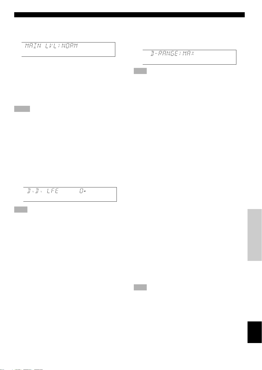
5. MAIN LVL
Choices: NORM (Normal)/–10 dB
Preset position: NORM (Normal)
NORM (Normal)
Normally select this position.
–10 dB
Select this position if the sound output from the main
speakers is too loud and cannot be balanced with the sound
output from the center and rear speakers. In this position,
the sound output from the main speakers is attenuated.
Notes
• The setting of “CENTER SP”, “REAR SP”, “MAIN SP” and
“BASS OUT” have no effect on a source connected to the 6CH
INPUT terminals on the rear of this unit.
• Once you have adjusted appropriately for “CENTER SP”, “REAR
SP”, “MAIN SP”, “BASS OUT” and “MAIN LVL”, you do not
have to change any settings unless your speaker system is
modified.
6. D.D. LFE (Adjusting the output
level of the LFE channel for Dolby
Digital)
Control range: –20 dB to 0 dB (in 1 dB steps)
Preset value: 0 dB
Note
• This adjustment is only effective when Dolby Digital is being
decoded and the selected source encoded with Dolby Digital
contains LFE signals.
This adjusts the output level of the LFE channel. If the LFE
signals are mixed with signals of other channels and they
are directed to the same speakers, the ratio of the LFE signal
level to the level of the other signals can be adjusted.
7. D-RANGE (Adjusting the dynamic
range)
Choices: MAX/STD (Standard)/MIN
Preset position: MAX
Note
• This adjustment is only effective when Dolby Digital is being
decoded.
“Dynamic range” is the difference between the maximum
level and the minimum level of sounds. Sounds on a movie
originally designed for movie theaters feature a very wide
dynamic range. Dolby Digital technology can modify the
original sound track into a home audio format with this
wide dynamic range unchanged. Powerful sounds of
extremely wide dynamic range are not always suitable for
home use. Depending on the condition of your listening
environment, it may not be possible to increase the sound
output to a level as high as that in a movie theater. However,
at the normal level suitable for listening in your room, the
low-level parts of source sound often cannot be heard well
because they will be lost among noise in your environment.
Dolby Digital technology has also made it possible to
reduce an original sound track’s dynamic range for a home
audio format by “compressing” the sound data.
MAX
In this position, a source encoded with Dolby Digital is
reproduced in the original sound track’s wide dynamic
range to provide you with powerful sounds just like those in
a movie theater. Selecting this position will be even better if
you can listen to a source at a high output level in a room
specially soundproofed for audio/video enjoyment.
STD (Standard)
In this position, a source encoded with Dolby Digital is
reproduced in the “compressed” dynamic range of the
source that is suitable for low-level listening.
MIN
In this position, the dynamic range is more reduced than in
the STD position. Selecting this position will be effective
when you must listen to a source at a low level.
Note
• It may happen that sound is output faintly or not output normally
depending on the source. In that case, select the MAX or STD
position.
ADV ANCED OPERA
TION APPENDIXINTRODUCTION PREP ARA TION
E-27
EnglishBASIC OPERATION
Page 30

SET MENU
8. DTS LFE (Adjusting the output
level of the LFE channel for DTS)
Control range: –10 dB to +10 dB (in 1 dB steps)
Preset value: 0 dB
Note
• This adjustment is effective only when DTS is being decoded and
the selected source encoded with DTS contains LFE signals.
This adjusts the output level of the LFE channel. If the LFE
signals are mixed with signals of other channels and they
are directed to the same speakers, the ratio of the LFE signal
level to the level of the other signals can be adjusted.
9. CNTR DELAY (Adjusting the delay
of the sound from the center
sound)
Control range: 0 ms to 5 ms (in 1 ms steps)
Preset value: 0 ms
This adjusts the delay between the main sound (on the main
channels) and dialog, etc. (on the center channel). The larger
the value, the later the dialog, etc. is generated.
This makes sounds from the left main, center and right main
speakers reach your listening position at the same time. This
is achieved by delaying the sound from the center speaker if
the distance from the center speaker to your listening
position is shorter than the distance from the right and left
main speaker to your listening position.
10.MEM. GUARD (Locking the
settings)
Choices: ON/OFF
Preset position: OFF
If you wish to prevent accidental alterations to the settings
of the SET MENU and other adjustments on this unit, select
the ON position. The following settings on this unit can be
locked:
• Settings of other items on the SET MENU
• Settings in the TIME/LEVEL mode
• Settings when using TEST
11.TV INPUT (Selecting the initial
input mode for a source connected
to the D-TV input terminals)
Choices: AUTO/LAST
Preset position: AUTO
The input mode for a source connected to the D-TV input
terminals of this unit can be automatically set when the
power of this unit is turned on. Refer to page 18 for details
about the input mode.
AUTO
In this position, the input mode is always set to AUTO.
LAST
In this position, the input mode is automatically set to that
selected the last time when the power of this unit was turned
on.
12.CBL INPUT (Selecting the initial
input mode for a source connected
to the CBL/SAT input terminals)
Choices: AUTO/LAST
Preset position: AUTO
E-28
The input mode for a source connected to the CBL/SAT
input terminals of this unit can be automatically set when
the power of this unit is turned on. Refer to page 18 for
details about the input mode.
AUTO
In this position, the input mode is always set to AUTO.
LAST
In this position, the input mode is automatically set to that
selected the last time when the power of this unit was turned
on.
Page 31

TEST
EFFECT
DSP
TIME/LEVEL SET MENU
DELAY TIME AND SPEAKER OUTPUT LEVELS
When using the digital sound field processor with the Dolby
Pro Logic decoder, Dolby Digital decoder or DTS decoder,
you can adjust the delay time between the main sound and
sound effect, and each speaker’s output level as you wish.
Note
• When high-rate 96-kHz sampling 24-bit digital signals are input
to this unit, the delay time and speaker output levels cannot be
adjusted.
Delay Time
You can adjust the time difference between the beginning of
the sound from the main speakers and the beginning of the
sound effect from the rear speakers. The larger the value,
the later the sound effect is generated. The delay time can be
individually adjusted to all DSP programs.
Notes
• Adding too much delay will cause an unnatural effect with some
sources.
• The sound is momentarily interrupted while adjusting the delay
time.
Program
1. PRO LOGIC/Normal 15 to 30 20
DOLBY DIGITAL/Normal 0 to 15 5
DTS DGTL SUR/Normal 0 to 15 5
PRO LOGIC/ENHANCED 15 to 30 20
DOLBY DIGITAL/ENHANCED 0 to 15 5
DTS DGTL SUR/ENHANCED 0 to 15 5
2. 70 mm SPECTACLE 15 to 30 23
DGTL SPECTACLE 1 to 99 15
DTS SPECTACLE 1 to 99 15
70 mm SCI-FI 15 to 30 20
DGTL SCI-FI 1 to 99 16
DTS SCI-FI 1 to 99 16
3. 70 mm ADVENTURE 15 to 30 20
DGTL ADVENTURE 1 to 99 15
DTS ADVENTURE 1 to 99 15
70 mm GENERAL 15 to 30 20
DGTL GENERAL 1 to 99 15
DTS GENERAL 1 to 99 15
4. MONO MOVIE 1 to 99 49
5. TV SPORTS 1 to 99 9
6. DISCO 1 to 99 40
7. ROCK CONCERT 1 to 99 16
8. CONCERT HALL 1 to 99 44
Control
range (ms)
Preset
value
Sound Output Level of the Center,
Right Rear and Left Rear Speakers,
and Subwoofer
If desired, you can adjust the sound output level of each
speaker even if it has already been adjusted in
“ADJUSTING THE SPEAKER BALANCE” on pages 14
and 15.
Notes
• The sound output level of the center speaker cannot be adjusted
when the input signal is analog, PCM audio, or encoded with
Dolby Digital in 2-channel.
• If “CENTER SP” on the SET MENU is set to the NONE position,
the sound output level of the center speaker cannot be adjusted.
This is because the center channel sound is automatically output
from the right and left main speakers.
• Once the sound output level has been adjusted, the level will be
the same for all DSP programs.
Speaker Control range (dB) Preset value
Center MIN, –20 to +10 0
Right rear MIN, –20 to +10 0
Left rear MIN, –20 to +10 0
Subwoofer MIN, –20 to 0 0
ADV ANCED OPERA
TION APPENDIXINTRODUCTION PREP ARA TION
E-29
EnglishBASIC OPERATION
Page 32

DELAY TIME AND SPEAKER OUTPUT LEVELS
POWER
PROGRAM
/DTS
SUR.
21
4
MOVIE
THTR 1
3
MOVIE
THTR 2
MONO MOVIE
7
ROCK
TEST
TIME/LEVEL
6CH INPUT
SET MENU
5
TV SPORTS
8
HALL
6
DISCO
EFFECT
DSP
DELAY
CENTER
R SUR.
L SUR.
SWFR
Adjusting Method
Adjustments should be performed with the remote control
while watching the information on the display.
2
1
1 Press TIME/LEVEL repeatedly to select the
item you want to adjust.
Each time you press TIME/LEVEL, the selected item
changes and appears on the display as shown below.
TIME/LEVEL
Memory back-up
The memory back-up circuit prevents the stored data
from being lost when this unit is set in the standby mode.
If, however, the power cord is disconnected from the AC
power outlet or the power is cut for more than one week,
the latest values for the delay time and the center/rear/
subwoofer output levels that were set will automatically
return to the preset values. If so, adjust the delay time
and output levels again.
Delay time
Center speaker output level
Right rear speaker output level
Left rear speaker output level
Subwoofer output level
Note
• Depending on the setting of the SET MENU, you may not be able
to select all these items.
2 Press l or h to adjust the
delay time or speaker
output levels.
3 Repeat steps 1 and 2 to adjust the settings of
any other item.
E-30
DSP
Page 33

TEST
EFFECT
DSP
TIME/LEVEL SET MENU
SLEEP TIMER
The SLEEP timer can be used to automatically set this unit
in the standby mode. This timer is useful when you are
going to sleep while enjoying the desired input source. The
SLEEP timer can only be set with the remote control.
Note
• The SLEEP timer is effective for the components connected to the
AC OUTLET on the rear panel of this unit.
Setting the SLEEP Timer
1 Play a source you want to enjoy when you are
going to sleep.
2 Press SLEEP repeatedly to
select the desired SLEEP
time.
Each time you press SLEEP, the
SLEEP time will change as
below:
120 90 60 30
The SLEEP timer is off
(SLEEP OFF).
(This is the state before
SLEEP is pressed.)
SLEEP
Canceling the Selected SLEEP
Timer
Press SLEEP repeatedly until “SLEEP OFF”
appears on the display.
It will soon disappear and the “SLEEP” indicator will
go off.
SLEEP
Note
• The SLEEP timer can also be canceled by setting the unit in the
standby mode by using POWER on the remote control (or
STANDBY/ON on the front panel), or by disconnecting the AC
power cord from the AC power outlet.
DVD/LD
TUNER
D–TV
CD
VCR
CBL/SAT
SLEEP
Flashes
3 The “SLEEP” indicator soon lights up on the
display after the SLEEP timer has been set.
The display returns to the previous indication.
DVD/LD
TUNER
D–TV
CD
VCR
CBL/SAT
SLEEP
Lights up
ADV ANCED OPERA
TION APPENDIXINTRODUCTION PREP ARA TION
EnglishBASIC OPERATION
E-31
Page 34

APPENDIX
TROUBLESHOOTING
If the unit fails to operate normally, check the following points to determine whether the fault can be corrected by the simple
measures suggested. If it cannot be corrected, or if the fault is not listed in the SYMPTOM column, disconnect the power
cord and contact your authorized YAMAHA dealer or service center.
■ General
SYMPTOM
The unit fails to turn on
when STANDBY/ON
(POWER) is pressed, or
enters in the standby
mode soon after the
power has been turned
on.
The unit does not work
normally.
No sound and/or no
picture.
No picture.
The sound suddenly
goes off.
Only the speaker on one
side can be heard.
No sound from the effect
speakers.
CAUSE
The power cord is not connected or the plug is
not completely inserted.
The IMPEDANCE SELECTOR switch on the
rear panel is not fully set to the right or left
position.
The internal microcomputer has been frozen by
an external electric shock (lightning, excessive
static electricity, etc.) or by a power supply with
low voltage.
Incorrect input or output cable connections.
An appropriate input source has not been
selected.
The speaker connections are not secure.
The sound is muted.
Digital signals other than PCM audio and the
signals encoded with Dolby Digital or DTS
which this unit cannot reproduce are being input
to this unit by a CD-ROM, etc.
There is no S VIDEO connection between this
unit and the TV monitor, although S video
signals are being input to this unit.
The protection circuit has been activated because
of a short circuit, etc.
The SLEEP timer has functioned.
Incorrect cable connections.
The sound effect is off.
A Dolby Surround, Dolby Digital or DTS
decoding DSP program is being used with
material not encoded with Dolby Surround,
Dolby Digital or DTS.
The 96-kHz sampling 24-bit digital signals are
input to this unit.
REMEDY
Firmly connect the power cord.
Set the switch fully to the right or left position
when the unit is in the standby mode.
Set the unit in the standby mode and disconnect
the AC power cord from the AC power outlet.
After about 30 seconds have passed, connect the
power and operate the unit again.
Connect the cables properly. If the problem
persists, the cables may be defective.
Select an appropriate input source with INPUT
SELECTOR or TAPE/MD MON / 6CH INPUT
(or the input selector buttons).
Secure the connections.
Set VOLUME to the “m” position, press
MUTING to cancel a mute and adjust the
volume.
Play a source whose signals this unit can
reproduce.
Connect the monitor’s “S” video input terminal
to this unit’s S VIDEO MONITOR OUT
terminal.
Set the unit in the standby mode and then turn
on to reset the protection circuit.
Turn on the power, and play the source again.
Connect the cables properly. If the problem
persists, the cables may be defective.
Press EFFECT to turn it on.
Select another DSP program.
Refer to
page
13
13
—
9, 10
16
11
17
—
11
—
31
11
20
24
19
E-32
Page 35

TROUBLESHOOTING
SYMPTOM
No sound from the main
speakers.
No sound from the
center speaker.
No sound from the rear
speakers.
No sound from the
subwoofer.
A “humming” sound can
be heard.
The volume level cannot
be increased, or the
sound is distorted.
The sound effect cannot
be recorded.
The DVD/LD, D-TV or
CBL/SAT source cannot
be recorded by tape
deck, MD recorder or
VCR connected to this
unit.
Adjusting this unit by
using SET MENU, TIME/
LEVEL or TEST cannot
be performed.
CAUSE
Incorrect output connection to the external
amplifier.
The external amplifier connected to this unit is
turned off.
The sound output level of the center speaker is
set to minimum.
“CENTER SP” on the SET MENU is set to the
NONE position.
Incorrect DSP program is selected.
The source encoded with Dolby Digital or DTS
does not have a center channel signal.
The output level of the rear speakers is set to
minimum.
A monaural source is being played with the PRO
LOGIC/Normal or PRO LOGIC/ENHANCED
program.
“BASS OUT” on the SET MENU is set to the
SW or MAIN position when playing a 2-channel
source.
The source does not contain low bass signals
(below 90 Hz).
Incorrect cable connections.
The component connected to the TAPE/MD
OUT (REC) terminals of this unit is in the
standby mode.
It is not possible to record the sound effect by a
tape deck or MD recorder connected to the
TAPE/MD OUT (REC) terminals of this unit.
The DVD/LD player, TV/digital TV or cable
TV/satellite tuner is connected to the unit only
through the digital terminals.
“MEM. GUARD” on the SET MENU is set to
the ON position.
REMEDY
Connect the external amplifier correctly.
Turn on the power to the external amplifier.
Raise the level of the center speaker.
Select the LRG or SML position.
Select the appropriate program.
Raise the output level of the rear speakers.
Select another DSP program suitable for the
monaural source.
Select the BOTH position.
Firmly connect the audio plugs. If the problem
persists, the cables may be defective.
Turn on the power to the component.
Make additional connections between the analog
terminals.
Set “MEM. GUARD” to the OFF position.
Refer to
page
11, 12
11, 12
29
26
22, 23, 24
—
29
24
26
—
9, 10
—
21
10
ADV ANCED OPERA
28
E-33
TION APPENDIXINTRODUCTION PREP ARA TION
EnglishBASIC OPERATION
Page 36

TROUBLESHOOTING
■ Remote control
SYMPTOM
The remote control does
not work.
Direct sunlight or lighting (from an inverter type
of fluorescent lamp, etc.) is striking the remote
control sensor of this unit.
The batteries are weak.
CAUSE
Reposition the unit.
Replace all batteries with new ones.
■ Others
SYMPTOM
The sound is degraded
when listening with
headphones to a tape
deck or CD player
connected to this unit.
There is noise
interference from digital
or high-frequency
equipment, or the unit.
This unit is in the standby mode.
The unit is too close to the digital or highfrequency equipment.
CAUSE
Turn on the power of the unit.
Move the unit further away from such
equipment.
■ When playing back a source encoded with DTS
SYMPTOM
A loud hissing noise is
heard when playing back
a source encoded with
DTS.
A percussive noise is
heard when playing back
a source encoded with
DTS.
No sound is heard when
playing back a source
encoded with DTS, even
if the input mode is set
to AUTO on this unit.
No sound is heard when
playing back an MD or
DAT on which has been
recorded a source
encoded with DTS.
No sound is heard when
playing back a source
(CD, etc.) even if the
currently selected input
mode is AUTO.
The player which plays back the source is not
connected to a digital audio signal input terminal
of this unit.
The input mode is set to ANALOG on this unit.
If the input mode is set to AUTO, depending on
some sources, there may be a noise heard while
this unit is identifying the format of the input
signal.
The built-in DTS decoder does not function
because the player has a digital volume control
and it is set at a position other than “maximum,”
“neutral” or “ineffective.”
A source encoded with DTS cannot be recorded
on an MD or DAT.
In the AUTO mode, the DTS-decoding mode
cannot be automatically changed to the normal
(PCM) digital signal input mode.
CAUSE
The player must be connected to a digital audio
signal input terminal of this unit besides the
analog audio signal terminal connections.
Set a proper input mode to turn on the built-in
DTS decoder.
Set the input mode of the currently selected
input source to DTS.
Set the player’s digital volume control at the
maximum, neutral or ineffective position.
Set the input mode to AUTO again.
REMEDY
REMEDY
REMEDY
Refer to
page
3
2
Refer to
page
—
—
Refer to
page
10
18
18
—
—
19
Notes
• It is necessary to use a DTS decoder to play back a source encoded with DTS, so the player which plays back the source must be connected
to a digital audio input terminal of this unit in the way described in this manual. If this connection is not made or only a D-to-A converter is
being used without using a DTS decoder, only a loud hissing noise will be heard when you play back the source.
• The “t” indicator will flash when the input mode is set to AUTO and a search or skip operation is performed while playing back a
source encoded with DTS. If this status continues for 30 or more seconds, the unit will automatically switch from DTS-decoding mode to
PCM digital signal input mode and the “t” indicator will go out.
E-34
Page 37

SPECIFICATIONS
AUDIO SECTION
• Minimum RMS Output Power
20 Hz to 20 kHz, 0.06% THD, 8 ohms
Center, Rear L/R......................................................................... 70 W
1 kHz, 0.09% THD, 8 ohms
Center, Rear L/R......................................................................... 80 W
• Maximum Output Power (EIAJ)
1 kHz, 10% THD, 8 ohms ........................................................ 105 W
• DIN Standard Output Power
1 kHz, 0.7% THD, 4 ohms
Center, Rear L/R....................................................................... 110 W
• IEC Output Power
1 kHz, 0.04% THD, 8 ohms ....................................................... 75 W
• Dynamic Power (IHF)
8/6/4/2 ohms ........................................................ 90/110/135/160 W
• Damping Factor
20 Hz to 20 kHz, 8 ohms ................................................................ 80
• Frequency Response
CD etc. to MAIN L/R.............................. 10 Hz to 100 kHz, 0/–3 dB
• Total Harmonic Distortion (20 Hz to 20 kHz)
6CH INPUT to REAR SP OUT, 35W/8 ohms....................... 0.06 %
• Signal-to-Noise Ratio (IHF-A Network)
CD etc. to MAIN PRE OUT
(250 mV, Input Shorted) ........................................................103 dB
• Residual Noise (IHF-A Network)
CENTER, REAR SP OUT ..................................................... 150 µV
• Input Sensitivity/Impedance
CD etc.................................................................. 150 mV/47 k-ohms
6CH INPUT......................................................... 150 mV/47 k-ohms
• Output Level/Impedance
REC OUT ........................................................... 150 mV/1.2 k-ohms
PRE OUT ................................................................1.0 V/1.2 k-ohms
SUBWOOFER ........................................................ 4.0 V/1.2 k-ohms
• Channel Separation (Vol. –30 dB)
CD etc. (Input 5.1 k-ohms terminated, 1 kHz/10 kHz)
..................................................................................... 60 dB/45 dB
GENERAL
• Power Supply ............................................................. AC 230 V, 50 Hz
• Power Consumption ....................................................................180 W
• AC Outlet (100 W max. total) ..................................... 1 (SWITCHED)
• Dimensions (W x H x D) ...................................... 435 x 126 x 391 mm
• Weight ....................................................................................... 10.0 kg
• Accessories ................................................................... Remote control
........................................................................................... Batteries
Specifications are subject to change without notice.
ADV ANCED OPERA
VIDEO SECTION
• Video Signal Type ...........................................................NTSC or PAL
• Video Signal Level .......................................................1 Vp-p/75 ohms
• Signal-to-Noise Ratio .................................................................. 50 dB
• Monitor Out Frequency Response .................... 5 Hz to 10 MHz, –3 dB
TION APPENDIXINTRODUCTION PREP ARA TION
EnglishBASIC OPERATION
E-35
Page 38

ATTENTION : TENIR COMPTE DES PRÉCAUTIONS CI-DESSOUS
AVANT DE FAIRE FONCTIONNER L’APPAREIL.
1. Pour garantir les meilleures performances possible,
lire ce manuel avec attention. Le garder dans un
endroit sûr pour une référence future.
2. Installer l’appareil dans un endroit frais, sec et
propre, loin de fenêtres, sources de chaleur et
d’endroits où les vibrations, la poussière, l’humidité
ou le froid sont importants. Eviter les sources de
bourdonnements (transformateurs, moteurs). Pour
éviter les incendies ou chocs électriques, ne pas
exposer l’appareil à la pluie ou à l’humidité.
3. Ne jamais ouvrir le coffret. Si un objet pénètre dans
l’appareil, contacter le revendeur.
4. Ne pas forcer les boutons, commandes ou câb les.
Lors du déplacement de l’appareil, débrancher
d’abord la prise d’alimentation et les câbles le
raccordant à d’autres appareils. Ne jamais tirer sur le
cordon.
5. Les ouvertures pratiquées sur le couvercle de
l’appareil assurent une ventilation adéquate de
l’appareil. Si ces ouvertures sont bouchées, la
température va s’élever rapidement à l’intérieur de
l’appareil. Par conséquent, éviter de placer des objets
sur ces ouvertures, et installer l’appareil dans un
endroit suffisamment ventilé pour éviter tout risque
d’incendie ou de dommages.
Veiller à laisser un espace d’au moins 20 cm derrière,
20 cm sur les deux côtés et 30 cm au-dessus du
panneau supérieur de l’appareil pour éviter tout
risque d’incendie ou de dommages.
6. Respecter la tension indiquée sur l’appareil. Le
fonctionnement sur une tension plus élevée est
dangereux et risque de provoquer un incendie ou
autre accident. YAMAHA ne sera pas tenu pour
responsable des dommages causés par le nonrespect de la tension spécifiée.
7. Il se peut que les signaux numériques produits par
cet appareil créent des interférences avec des tuners,
amplituners ou téléviseurs. Dans ce cas, éloigner cet
appareil des appareils en question.
8. Toujours régler la commande de volume sur “m”
avant de commencer la lecture d’une source audio ;
augmenter petit à petit le volume jusqu’à un niveau
adéquat une fois que la lecture a commencé.
9. Ne pas essayer de nettoyer l’appareil avec des
diluants chimiques ; ceci endommagerait sa finition.
Utiliser un chiffon propre et sec.
10. Bien lire la section “EN CAS DE DIFFICULTÉ”
concernant les erreurs de fonctionnement communes
avant de conclure que l’appareil est en panne.
11. Lorsqu’on prévoit de ne pas utiliser cet appareil
pendant longtemps (pendant les vacances, par
exemple), débrancher le cordon d’alimentation de la
prise de courant.
12. Pour éviter des dommages dus à la foudre,
débrancher le cordon d’alimentation en cas d’orage.
13. Mise à la terre ou polarisation — Des précautions
doivent être prises de manière que la mise à la terre
ou la polarisation d’un appareil ne soit pas annulée.
14. Ne pas raccorder d’appareil audio aux prises CA du
panneau arrière si sa consommation est supérieure à
la capacité nominale des prises.
Cet appareil n’est pas déconnecté du secteur tant qu’il
reste branché à la prise de courant. Il se trouve alors “en
veille”. En mode veille, l’appareil consomme une très
faible quantité de courant.
ATTENTION
Page 39

INTRODUCTION
CARACTÉRISTIQUES
En raccordant le DSP-E800 à l’amplificateur de la chaîne,
on peut obtenir un son surround avancé avec un système 5.1
canaux.
Amplification de puissance 3 canaux
intégrée
◆ Puissance de sortie efficace minimum (distorsion
harmonique totale de 0,06%, 20 Hz à 20 kHz)
Central : 70 W (8 Ω)
Arrière : 70 W + 70 W (8 Ω)
Processeur de champ sonore numérique
multi-modes
◆ Processeur de champ sonore numérique (DSP)
◆ Décodeur Dolby Prologic
◆ Décodeur Dolby Digital
◆ Décodeur DTS
◆ CINEMA DSP : utilisation combinée de la
technologie YAMAHA DSP et de l’un des
décodeurs Dolby Prologic, Dolby Digital ou DTS
Autres caractéristiques
◆ Convertisseur N/A 96 kHz/24 bits
◆ Menu de réglage (“SET MENU”) à douze
paramètres permettant d’adapter avec precision cet
appareil à votre chaîne audio/vidéo
◆ Générateur de signal test facilitant l’équilibrage du
son entre les enceintes
◆ Entrée décodeur externe 6 canaux pour les futurs
formats sonores
◆ Entrée/sortie S-Vidéo possible
◆ 3 bornes d’entrée numérique optique/2 bornes
d’entrée numérique coaxiale
◆ Minuterie de mise en veille (SLEEP)
◆ Télécommande
TABLE DES MATIÈRES
INTRODUCTION
CARACTÉRISTIQUES .............................................. 1
TABLE DES MATIÈRES ........................................... 1
MISE EN ROUTE ....................................................... 2
LES COMMANDES ET LEURS FONCTIONS ...... 4
PRÉPARATION
INSTALLATION DES ENCEINTES......................... 7
RACCORDEMENTS .................................................. 8
ÉQUILIBRAGE DU SON ENTRE LES
ENCEINTES ........................................................... 14
UTILISATION DE BASE
UTILISATION DE BASE
LECTURE D’UNE SOURCE................................... 16
EFFET DU PROCESSEUR DE CHAMP
SONORE NUMÉRIQUE (DSP) ............................ 20
ENREGISTREMENT D’UNE SOURCE SUR
UNE CASSETTE, UN MINIDISC OU UNE
CASSETTE VIDÉO ............................................... 21
UTILISATION AVANCÉE
UTILISATION AVANCÉE
PROGRAMMES DSP ............................................... 22
SET MENU................................................................. 25
RÉGLAGE DU TEMPS DE RETARD ET DU
NIVEAU DE SORTIE DES ENCEINTES ........... 29
MINUTERIE DE MISE EN VEILLE ..................... 31
Fabriqué sous licence de Dolby Laboratories.
“Dolby”, “Pro Logic” et le symbole double-D
sont des marques commerciales de Dolby
Laboratories.
© 1992–1997 Dolby Laboratories, Inc. Tous
droits réservés.
Fabriqué sous licence de Digital Theater Systems, Inc. Brevet
n° 5.451.942 aux Etats-Unis et autres brevets publiés et en
cours d’établissement. Les logos “DTS”, “DTS Digital
Surround”, sont des marques commerciales de Digital Theater
Systems, Inc., droits d’auteur 1996 de Digital Theater Systems,
inc. Tous droits réservés.
Travail non publié confidentiel.
ANNEXES
EN CAS DE DIFFICULTÉ ....................................... 32
CARACTÉRISTIQUES TECHNIQUES ................ 35
y indique un conseil d’utilisation.
• Lorsque les touches sur cet appareil et la télécommande
sont indiquées ensemble dans ce Mode d’emploi, les
noms de touche sont en principe indiqués dans l’ordre de
“nom de la touche (nom de la touche de la
télécommande)”.
F-1
ANNEXESINTRODUCTION PRÉPARATION
Français
Page 40

MISE EN ROUTE
Vérification du contenu de
l’emballage
S’assurer qu’aucune des pièces suivantes ne manque :
Télécommande Piles (type R6)
POWER
PROGRAM
/DTS
MOVIE
MOVIE
SUR.
THTR 1
THTR 2
21
3
MONO MOVIE
TV SPORTS
DISCO
4
5
6
ROCK
HALL
7
8
TEST
EFFECT
DSP
TIME/LEVEL
SET MENU
6CH INPUT
CD TUNER TAPE/MD
DVD/LD D–TV VCR
CBL/SAT
SLEEP MUTING
+
–
VOLUME
Mise en place des piles dans la
télécommande
1
3
2
1 Retourner la télécommande à l’envers et ouvrir
le couvercle du compartiment des piles en le
faisant glisser dans le sens de la flèche.
2 Insérer les piles (type R6) en respectant les
polarités inscrites à l’intérieur du
compartiment.
3 Refermer le couvercle du compartiment des
piles.
Remplacement des piles
Si la télécommande ne fonctionne plus qu’à proximité de
l’appareil, les piles sont usées. Les remplacer alors toutes
par des neuves.
Remarques
• N’utiliser que des piles R6 comme piles de rechange.
• Veiller à ce que les polarités des piles soient respectées (voir
l’illustration à l’intérieur du compartiment des piles.)
• Retirer les piles si l’on prévoit que la télécommande restera
longtemps inutilisée.
• Si les piles ont coulé, les jeter immédiatement. Ne pas toucher du
liquide ayant fui et éviter qu’il vienne en contact avec des
vêtements, etc. Nettoyer complètement le compartiment des piles
avant de mettre en place des piles neuves.
F-2
Page 41

Utilisation de la télécommande
DIGITAL
DOLBY
NATURAL SOUND AV PROCESSOR/AMPLIFIER DSP–E800
STANDBY/ON
+–
Capteur de
télécommande
La télécommande émet un faisceau infrarouge directionnel.
On doit donc la diriger directement vers le capteur
infrarouge de l’appareil. Si le capteur est masqué ou s’il y a
un obstacle important entre la télécommande et lui, il ne
recevra pas les signaux. Il se peut aussi que le capteur ne
reçoive pas correctement les signaux s’il est exposé aux
rayons directs du soleil ou à une forte lumière artificielle
(éclairage fluorescent ou stroboscopique, par exemple).
Changer alors la direction de l’éclairage ou la position de
l’appareil.
Remarques
• Manipuler la télécommande avec précaution.
• Ne pas renverser de liquide (eau, thé, etc.) sur la télécommande.
• Ne pas faire tomber la télécommande.
• Ne pas laisser ou ranger la télécommande dans les conditions
suivantes :
– forte humidité ou chaleur (proximité d’un chauffage, four ou
bain) ;
– endroits poussiéreux ;
– endroits très froids.
CINEMA DSP
DIGITAL
SURROUND
INPUT SELECTOR
INPUT MODE
EFFECTTAPE/MD MON
NEXT
PROGRAMSET MENU
/6CH INPUT
6 m maximum environ
VOLUME
16
12
20
8
28
4
40
2
60
00 0
–dB
MISE EN ROUTE
INTRODUCTION PREP ARA TION
ADV ANCED OPERA
TION APPENDIX
F-3
FrançaisBASIC OPERATION
Page 42

Panneau avant
LES COMMANDES ET LEURS FONCTIONS
12
NATURAL SOUND AV PROCESSOR/AMPLIFIER DSP–E800
STANDBY/ON
NEXT
+–
3
EFFECTTAPE/MD MON
/6CH INPUT
0987
1 STANDBY/ON
Appuyer sur cette touche pour allumer l’appareil ou le
mettre en veille. Avant d’allumer l’appareil, régler
VOLUME sur la position “m”.
Mode veille
Dans ce mode, l’appareil consomme une très faible
quantité de courant afin de pouvoir continuer à capter les
signaux infrarouges de la télécommande.
2 Capteur de télécommande
Reçoit les signaux provenant de la télécommande.
3 Affichage
Indique diverses informations (voir page 5).
4 INPUT MODE
Appuyer sur cette touche pour sélectionner le mode d’entrée
AUTO, DTS ou ANALOG pour les sources DVD/LD, DTV et CBL/SAT.
5 INPUT SELECTOR
Tourner ce sélecteur pour choisir la source d’entrée
(TUNER, CD, VCR, CBL/SAT, D-TV, DVD/LD) que l’on
désire écouter ou regarder. La flèche de l’indicateur de la
source d’entrée sélectionnée s’allume sur l’affichage.
6 VOLUME
Tourner cette commande pour augmenter ou diminuer le
volume.
56
VOLUME
20
28
40
60
00 0
CINEMA DSP
DOLBY
DIGITAL
PROGRAMSET MENU
DIGITAL
SURROUND
4
INPUT SELECTOR
INPUT MODE
q
7 SET MENU +/–
Appuyer sur ces touches pour régler les paramètres de SET
MENU.
8 NEXT
Appuyer sur cette touche pour sélectionner une option sur
SET MENU. Dans SET MENU, cette touche fonctionne
comme la touche
9 TAPE/MD MON / 6CH INPUT
Appuyer sur cette touche pour sélectionner une cassette ou
un minidisc comme source. L’indicateur “TAPE/MD
MONITOR” s’allume sur l’affichage. Si l’on appuie à
nouveau sur cette touche, l’indicateur “TAPE/MD
MONITOR” s’éteint, “6CH INPUT” s’affiche et l’on peut
écouter une source raccordée aux bornes 6CH INPUT.
0 EFFECT
Appuyer sur cette touche pour activer ou désactiver les
enceintes d’effet (centrale et arrière). Lorsque ces enceintes
sont désactivées, les signaux des canaux central et arrière
sont dirigés vers les enceintes principales droite et gauche
lors de la lecture d’une source codée en Dolby Digital et
DTS. Il est alors possible que les niveaux de sortie des
enceintes droite et gauche ne soient pas égaux.
q Sélecteur PROGRAM
Appuyer sur l ou h pour sélectionner un programme DSP
quand les enceintes d’effet (centrale et arrière) sont activées.
Le nom du programme sélectionné s’affiche.
de la télécommande.
16
12
8
4
2
–dB
F-4
Page 43

Panneau d’affichage
LES COMMANDES ET LEURS FONCTIONS
2
76
5
1
DIGITAL
PRO LOGIC
DSP
ENHANCED MOVIE THEATER 12
1 Indicateur t
L’indicateur “t” s’allume lorsque le décodeur DTS
interne est activé.
2 Affichage multi-informations
Cet affichage fournit des informations telles que le nom du
programme DSP sélectionné et les options choisies lors du
réglage avec SET MENU.
3 Indicateurs de source d’entrée
La flèche de l’indicateur de la source sélectionnée s’allume.
4 Indicateur TAPE/MD MONITOR
Cet indicateur s’allume lorsqu’on sélectionne la platine
cassette ou la platine minidisc, etc., comme source d’entrée
en appuyant sur TAPE/MD MON / 6CH INPUT (ou sur
T APE/MD).
TUNER
CD
CBL/SAT
TAPE/MD
MONITOR
SLEEP
4
3
DVD/LD
dB
ms
D–TV
VCR
8
5 Indicateurs g et o
L’indicateur “ g ” s’allume lorsque le décodeur
Dolby Digital est activé. L’indicateur “ o ”
s’allume lorsque le décodeur Dolby Prologic est activé.
6 Indicateur x
L’indicateur “ x ” s’allume lorsque le processeur
de champ sonore numérique est activé.
7 Indicateurs de programme DSP
Ces indicateurs s’allument lorsque le programme DSP n° 2,
3 ou le sous-programme “ENHANCED” du n° 1 est
sélectionné.
8 Indicateur SLEEP (minuterie de mise en veille)
Cet indicateur s’allume lorsque la minuterie de mise en
veille fonctionne.
INTRODUCTION PREP ARA TION
ADV ANCED OPERA
F-5
TION APPENDIX
FrançaisBASIC OPERATION
Page 44

LES COMMANDES ET LEURS FONCTIONS
Télécommande
POWER
1
2
3
4
5
6
1 POWER
À chaque pression sur cette touche, l’appareil passe
alternativement entre l’état allumé et le mode de veille.
2 TEST
Appuyer sur cette touche pour émettre un signal de test pour
chaque enceinte.
PROGRAM
/DTS
MOVIE
SUR.
THTR 1
21
MONO MOVIE
TV SPORTS
4
5
ROCK
HALL
7
8
TEST
DSP
TIME/LEVEL
6CH INPUT
CD TUNER TAPE/MD
DVD/LD D–TV VCR
CBL/SAT
SLEEP MUTING
–
VOLUME
MOVIE
THTR 2
3
DISCO
6
EFFECT
SET MENU
7
8
9
0
q
w
+
e
5 6CH INPUT
Appuyer sur cette touche pour sélectionner la source
raccordée aux bornes 6CH INPUT.
6 SLEEP
Appuyer sur cette touche pour régler la minuterie de mise
en veille (SLEEP).
7 Touches de sélection PROGRAME
Ces touches permettent de sélectionner un programme DSP.
8 EFFECT
Appuyez sur cette touche pour activer ou désactiver les
enceintes d’effet (centrale et arrière).
9
(suivant), (précédent)
Ces touches permettent d’avancer ou de reculer d’une
sélection en mode SET MENU et TIME/LEVEL.
0 SET MENU
Appuyer sur cette touche pour sélectionner les paramètres
de SET MENU.
q Touches du sélecteur d’entrée
Ces touches permettent de sélectionner la source d’entrée.
CD : pour la lecture d’un CD
TUNER : pour écouter une station FM ou AM
TAPE/MD : pour la lecture d’une cassette ou d’un
minidisc
DVD/LD : pour la lecture d’un disque DVD
D-TV : pour regarder une émission de télévision
VCR : pour la lecture d’une cassette vidéo
CBL/SAT : pour regarder une émission de télévision par
câble ou satellite
w MUTING
Appuyer sur cette touche pour mettre le son en sourdine.
Pour désactiver la mise en sourdine du son, appuyer à
nouveau sur cette touche.
e VOLUME +/–
Ces touches permettent de régler le volume du son.
+ : pour augmenter le volume
– : pour diminuer le volume
3 l (gauche), h (droite)
Ces touches permettent de régler les paramètres des modes
SET MENU et TIME/LEVEL.
4 TIME/LEVEL
Appuyer sur cette touche pour sélectionner les paramètres
du mode TIME/LEVEL.
F-6
Page 45

PRÉPARATION
INSTALLATION DES ENCEINTES
Choix des enceintes
La qualité du champ sonore de cet appareil est la meilleure
avec cinq enceintes : deux enceintes principales, deux
enceintes arrière et une enceinte centrale. Si les enceintes
utilisées ne sont pas toutes de la même marque
(caractéristiques sonores différentes), il se peut que le
mouvement des sons (voix humaines, etc.) qui se déplacent
ne soit pas régulier. Nous recommandons donc d’utiliser des
enceintes de la même marque ou ayant les mêmes
caractéristiques sonores.
Les enceintes principales sont utilisées pour le son principal
et les effets sonores. Ce seront probablement les enceintes
de votre chaîne stéréo actuelle. Les enceintes arrière sont
utilisées pour les effets sonores et les sons d’ambiance.
L’enceinte centrale est utilisée pour les sons centraux
(dialogues, voix, etc.). Il n’est pas indispensable d’utiliser
une enceinte centrale, mais c’est avec les cinq enceintes que
l’on obtiendra les meilleurs résultats.
Les enceintes principales doivent être des modèles de haute
performance et pouvoir accepter la puissance maximale de
la chaîne. Il n’est pas nécessaire que les autres enceintes
aient le même niveau de performances. Pour obtenir une
localisation précise des sons, il est toutefois préférable que
les enceintes centrale et arrière soient elles aussi des
modèles de haute performance pouvant restituer les sons sur
tout le spectre sonore.
■ Un subwoofer étend le champ
sonore
Il est également possible d’étendre davantage le champ
sonore de la chaîne en y ajoutant un subwoofer. Le
subwoofer renforce non seulement les basses fréquences des
canaux individuellement ou globalement, mais restitue aussi
fidèlement le son du canal LFE (effets basses fréquences)
lors de la lecture d’une source de son codé Dolby Digital ou
DTS. Le subwoofer “YAMAHA Active Servo Processing
Subwoofer System” est le choix idéal car il assure une
reproduction des graves à la fois naturelle et vivante.
Emplacement des enceintes
Disposer les enceintes comme sur le schéma ci-dessous.
Enceinte principale
(droite)
Enceinte arrière
(droite)
Subwoofer
Enceinte
principale
(gauche)
Enceinte centrale
■ Enceintes principales
Placer les enceintes principales droite et gauche à égale
distance de la position d’écoute idéale. Ces enceintes
doivent aussi se trouver à une même distance de part et
d’autre du téléviseur.
■ Enceintes arrière
Placer ces enceintes derrière la position d’écoute à une
hauteur de 1,8 m environ en les tournant légèrement vers
l’intérieur.
■ Enceinte centrale
Aligner la façade de l’enceinte centrale sur celle du
téléviseur. Placer l’enceinte aussi près du téléviseur que
possible (directement au-dessous ou au-dessus) au milieu
des deux enceintes principales.
Remarque
• Si l’on utilise pas d’enceinte centrale, on entendra le son
correspondant par les enceintes principales droite et gauche.
L’option NONE a été choisie pour le paramètre “CENTER SP” de
SET MENU. (Voir page 26.)
■ Subwoofer
La position du subwoofer est moins importante car les sons
graves sont moins directionnels que les sons aigus. Il est
toutefois recommandé de le placer près des enceintes
principales. Le tourner légèrement vers le centre de la pièce
pour réduire la réflexion contre les murs.
1,8 m
Enceinte arrière
(gauche)
INTRODUCTION
PRÉP ARA TION
ADV ANCED OPERA
TION APPENDIX
ATTENTION
Certains types d’enceintes peuvent perturber la réception
de télévision. Éloigner alors les enceintes du téléviseur.
S’il n’y a pas d’autre solution que d’installer l’enceinte
centrale ou le subwoofer près du téléviseur, utiliser des
enceintes à blindage magnétique.
F-7
FrançaisBASIC OPERATION
Page 46

RACCORDEMENTS
V V
C C
L
R
L
R
Avant de raccorder les éléments de la chaîne
ATTENTION
Ne jamais brancher cet appareil ou un autre élément de la chaîne au secteur tant que tous les raccordements ne sont pas
terminés.
Veiller à effectuer tous les raccordements correctement, c’est-à-dire en connectant L (gauche) à L, R (droite) à R, “+” à “+” et
“–” à “–”. Pour certains éléments, il se peut que la méthode et les noms des bornes soient différents. Consulter le mode
d’emploi de chaque élément à raccorder à cet appareil.
Pour raccorder d’autres éléments audio YAMAHA (platine cassette, platine minidisc, lecteur de compact disque, changeur de
compact disque, etc.), connecter les bornes de même numéro (!, @, #, $, etc.). YAMAHA applique ce système de
numérotation des bornes à tous ses produits.
Utiliser des câbles à fiches RCA pour le raccordement des appareils audio/vidéo sauf dans les cas indiqués plus loin.
On distingue les bornes d’entrée et de sortie pour fiches RCA comme suit :
Jaune signaux vidéo (composite)
Blanc signaux audio analogiques pour le canal gauche
Rouge signaux audio analogiques pour le canal droit
signaux numériques “coaxial”
Après avoir terminé tous les raccordements, les vérifier à nouveau pour s’assurer qu’ils sont corrects.
Raccordement à un
décodeur externe
(page 9)
MAIN
MAIN IN
L
R
L
R
CD TUNER
SURROUND
1 2 3 4
IN OUT MONITOR
VCR
S VIDEO SIGNAL
6CH
INPUT
EXTERNAL
DECODER
DVD/LD D–TV CBL/SAT
Raccordement d’un
élément audio (page 9)
Bornes d’entrée de
signal numérique
(page 10)
CENTER
IN (PLAY)
TAPE/MD
SUB
WOOFER
AUDIO SIGNAL
OUT (REC)
DVD/LD D–TV CBL/SAT
OUT
DIGITAL SIGNAL
DVD/LD D–TV CBL/SAT
OPTICAL COAXIAL
DVD/LD
D–TV CBL/SAT
VIDEO SIGNAL
Raccordement d’un élément
vidéo (pages 10 et 11)
DVD/LD CBL/SAT
IN
IN
Raccordement des
enceintes
(page 11)
L
R
OUT
VCR
OUT MONITOR
OUT
VCR
SPEAKERS
CAUTION
SEE INSTRUCTION MANUAL FOR CORRECT SETTING.
CENTER REAR
R
+
–
Raccordement de
l’amplificateur externe
(page 11) (Modèle Europe)
(SURROUND)
L
OUTPUT
MAIN
REAR
(SURROUND)
L
R
CENTER
WOOFER
SUB
IMPEDANCE SELECTOR
SET BEFORE POWER ON
REAR
: 4ΩMIN./SPEAKER
CENTER
: 4ΩMIN./SPEAKER
REAR
: 8ΩMIN./SPEAKER
CENTER
: 8ΩMIN./SPEAKER
IMPEDANCE SELECTOR
(Sélecteur d’impédance) (page 13)
Vers prise secteur
AC OUTLET
SWITCHED
100W MAX.
Branchement des cordons
d’alimentation (page 13)
F-8
Page 47

Raccordement d’un élément audio
A
RACCORDEMENTS
Lecteur de
compact disque
OUTPUT
L R
MAIN IN
MAIN
L
R
L
R
CD TUNER
S VIDEO SIGNAL
6CH
INPUT
EXTERNAL
DECODER
DVD/LD D–TV CBL/SAT
OUTPUT
Tuner
SURROUND
CENTER
SUB
WOOFER
AUDIO SIGNAL
IN (PLAY)
OUT (REC)
TAPE/MD
1 2 3 4
IN OUT MONITOR
VCR
L R
L R
LINE OUT
L
R
DVD/LD D–TV CBL/SAT
OPTICAL COAXIAL
DVD/LD D–TV CBL/SAT
OUT
D–TV CBL/SAT
DVD/LD
Platine cassette ou
platine minidisc
Signal analogique
Sens du signal
DIGITAL SIGNAL
DVD/LD CBL/SAT
L
R
IN
OUT
VCR
IN
OUT MONITOR
OUT
VCR
VIDEO SIGNAL
L R
LINE IN
Raccorder correctement le canal droit (R), le canal gauche
(L), l’entrée (IN) et la sortie (OUT).
INTRODUCTION
PRÉP ARA TION
Raccordement à un décodeur externe
Décodeur externe
MAIN
OUT
L R L R
6CH
INPUT
EXTERNAL
DECODER
MAIN IN
DVD/LD D–TV CBL/SAT
EXTERNAL
DECODER
Commutateur EXTERNAL
DECODER/MAIN IN
SURROUND
OUT
MAIN
SURROUND
L
R
L
R
CD TUNER
1 2 3 4
IN OUT MONITOR
S VIDEO SIGNAL
MAIN IN
CENTER
IN (PLAY)
VCR
CENTER
OUT
SUB
WOOFER
AUDIO SIGNAL
OUT (REC)
TAPE/MD
OUT
SUBWOOFER
OUT
DIGITAL SIGNAL
DVD/LD D–TV CBL/SAT
OPTICAL COAXIAL
DVD/LD D–TV CBL/SAT
DVD/LD
D–TV CBL/SAT
VIDEO SIGNAL
DVD/LD CBL/S
IN
VCR
IN
VCR
OUT
OUT
Cet appareil est doté de bornes d’entrée audio 6 canaux
supplémentaires pour la connexion d’un décodeur externe.
Placer le commutateur EXTERNAL DECODER/MAIN IN
sur la position EXTERNAL DECODER. Raccorder les
bornes de sortie audio 6 canaux du décodeur aux bornes
6CH INPUT de cet appareil.
ATTENTION
Toujours mettre l’appareil en veille avant de changer la
position du commutateur EXTERNAL DECODER/
MAIN IN.
Remarques
• Lorsqu’on sélectionne une source raccordée à ces bornes, le DSP
ne peut pas être utilisé.
• Les options choisies pour les paramètres “CENTER SP”, “REAR
SP”, “MAIN SP” et “BASS OUT” de SET MENU sont sans effet
sur une source connectée à ces bornes. L’option choisie pour le
paramètre “MAIN LVL” a un effet sur la source. (Pour plus
d’informations, voir pages 26 et 27.)
• Le réglage du niveau de sortie de l’enceinte centrale, des
enceintes arrière et du subwoofer est effectif lorsqu’on
sélectionne une source raccordée à ces bornes comme source
d’entrée. (Pour plus d’informations, voir page 29.)
ADV ANCED OPERA
TION APPENDIX
FrançaisBASIC OPERATION
F-9
Page 48

RACCORDEMENTS
R
Raccordement d’un élément vidéo
Lecteur DVD/
laserdisc
L R
ANALOG
AUDIO
OUT
MAIN
L
R
IN
L
R
CD TUNER
1 2 3 4
SURROUND
DIGITAL SIGNAL
DIGITAL
SIGNAL
(OPTICAL)
CENTER
WOOFER
IN (PLAY)
OUT (REC)
TAPE/MD
DIGITAL
SIGNAL
(OPTICAL)
ANALOG
AUDIO OUT
Téléviseur/
téléviseur numérique
L
Signal analogique
R
(COAXIAL)
O
DVD/LD D–TV CBL/SAT
SUB
AUDIO SIGNAL
DVD/LD D–TV CBL/SAT
Décodeur câble/
satellite
DIGITAL
SIGNAL
(OPTICAL)
C
O
DIGITAL SIGNAL
DVD/LD CBL/SAT
OPTICAL COAXIAL
IN
O
L R
Magnétoscope
C
DIGITAL
SIGNAL
(COAXIAL)
C
ANALOG
AUDIO
OUT
L
R
OUT
VCR
L RL R
AUDIO
OUT
AUDIO
IN
Signal numérique
(coaxial)
L R
Remarques
• Toujours remettre les caches sur les bornes OPTICAL lorsqu’elles
ne sont pas utilisées pour les protéger contre la poussière.
• Si le lecteur de laserdisc comporte une borne de sortie Dolby
Digital RF, utiliser le démodulateur RF (vendu séparément).
• On n’entend aucun son lorsqu’on raccorde directement la borne
de sortie Dolby Digital RF d’un lecteur de laserdisc à la borne
d’entrée numérique COAXIAL DVD/LD de cet appareil.
y
• Lorsque l’option AUTO est choisie pour le mode d’entrée, la
sélection du signal d’entrée aux bornes d’entrée DVD/LD ou
CBL/SAT s’effectue dans l’ordre de priorité suivant : borne
COAXIAL → borne OPTICAL → borne analogique. Pour plus
d’informations, voir page 18.
• Toutes les bornes d’entrée de signal numérique acceptent des
fréquences d’échantillonnage de 32 kHz, 44,1 kHz, 48 kHz et
96 kHz. (Pour les signaux numériques 24 bits d’échantillonnage
96 kHz, voir page 19.)
■ Bornes de signal vidéo
(composite)
Si les éléments vidéo ne comportent pas de borne “S”
Vidéo, on peut les raccorder aux bornes VIDEO de cet
appareil. Veiller à raccorder correctement l’entrée (IN) et la
sortie (OUT).
Téléviseur/
téléviseur numérique
Téléviseur
O
Signal numérique
(optique)
■ Bornes de signal audio
Raccorder correctement le canal droit (R), le canal gauche
Sens du signal
Lecteur DVD/
laserdisc
VIDEO
OUT
V
VIDEO OUT
V
VIDEO IN
V
(L), l’entrée (IN) et la sortie (OUT).
Remarque
• Effectuer également les raccordements vidéo.
■ Bornes de signal audio numérique
Si l’on utilise un lecteur DVD/laserdisc, un téléviseur/
téléviseur numérique ou un décodeur câble/satellite, etc.,
équipé de bornes de sortie numérique coaxiales ou optiques,
DVD/LD D–TV CBL/SAT VCR
V
VIDEO SIGNAL
VIDEO
OUT
IN
DVD/LD D–TV CBL/SAT
VIDEO
OUT
VCR
OUT MONITOR
VV
OUT
VIDEO
IN
on peut raccorder celles-ci aux bornes d’entrée numérique
COAXIAL et/ou OPTICAL de cet appareil. Pour ceci,
retirer les caches protégeant les bornes, puis raccorder les
bornes à l’aide d’un câble à fibre optique en vente dans le
V
Décodeur câble/
satellite
Signal vidéo
Magnétoscope
Sens du signal
commerce conforme aux normes EIA. Les autres câbles
risquent de ne pas donner de bons résultats.
Lorsqu’on utilise les bornes de signal numérique pour le
raccordement, il faut aussi raccorder l’appareil externe aux
bornes de signal audio analogique de même nom de cet
appareil. En effet, un signal numérique ne peut pas être
Remarques
• Effectuer également les raccordements audio.
• Si les signaux vidéo entrent à la fois par les bornes d’entrée S
VIDEO et les bornes d’entrée composite, ils sont dirigés vers les
bornes de sortie respectives.
enregistré par une platine cassette, une platine minidisc ou
un magnétoscope raccordés à cet appareil.
F-10
Page 49

E
M
M
M
M
1 2 3 4
V
■ Bornes S VIDEO
Téléviseur/
téléviseur numérique
S VIDEO
OUT
DVD/LD D–TV CBL/SAT
S
S VIDEO
OUT
Décodeur câble/
S
IN OUT MONITOR
S VIDEO SIGNAL
S VIDEO
OUT
satellite
S
VCR
S S
S VIDEO
IN
S VIDEO
OUT
OUT
D
S
Téléviseur
S VIDEO IN
S
Signal S Vidéo
Sens du signal
RACCORDEMENTS
Si les éléments vidéo sont dotés de bornes “S” (haute
résolution) vidéo, on peut les raccorder aux bornes S
VIDEO de cet appareil. Raccorder correctement l’entrée
(IN) et la sortie (OUT).
Remarques
• Utiliser un câble S VIDEO spécial (en vente dans le commerce)
pour la connexion S VIDEO.
• Si les signaux vidéo entrent à la fois par les bornes d’entrée S
VIDEO et les bornes d’entrée composite, ils sont dirigés vers les
bornes de sortie respectives.
INTRODUCTION
PRÉP ARA TION
Lecteur DVD/
laserdisc
Magnétoscope
Raccordement des enceintes et de l’amplificateur externe
L
R
MAIN
L R
R
Système de
subwoofer
OUTPUT
REAR
CENTER
(SURROUND)
L
IMPEDANC
SET BEFORE
REAR
: 4Ω
: 4Ω
CENTER
REAR
: 8Ω
: 8Ω
CENTER
SUB
WOOFER
Enceinte principale
Gauche
Raccordements de base
Il est nécessaire de raccorder un amplificateur 2 canaux à
cet appareil pour l’attaque des enceintes principales.
Raccorder correctement le canal droit (R) et le canal gauche
(L) en veillant à ce que la polarité “+” (rouge) et “–” (noir)
soit correcte. Si les connexions sont défectueuses, les
enceintes ne produiront pas de son. Si la polarité des
connexions est inversée, le son ne sera pas naturel et les
basses manqueront de profondeur.
■ Raccordement d’un amplificateur 2
canaux
Raccorder les bornes d’entrée d’un amplificateur de
puissance 2 canaux aux bornes MAIN OUTPUT de cet
appareil. Si l’on raccorde les bornes d’entrée AUX de
l’amplificateur externe aux bornes MAIN OUTPUT de cet
appareil, régler le volume de l’amplificateur externe autour
de –16 dB à –18 dB.
■ Raccordement d’enceintes arrière
Raccorder des enceintes arrière aux bornes de sortie REAR
SPEAKER (SURROUND) de cet appareil.
■ Raccordement d’une enceinte
centrale
Raccorder une enceinte centrale aux bornes de sortie
CENTER SPEAKER de cet appareil.
■ Raccordement d’un subwoofer
Raccorder la borne d’entrée d’un subwoofer à la borne
SUBWOOFER OUTPUT de cet appareil.
Enceintes arrière
Gauche
Droite
Enceinte
centrale
SPEAKERS
CAUTION
SEE INSTRUCTION MANUAL FOR CORRECT SETTING.
CENTER REAR
(SURROUND)
L
R
+
–
Enceinte principale
Droite
MAIN
IN
Amplificateur de
puissance 2 canaux
ATTENTION
• Utiliser des enceintes ayant l’impédance indiquée à
l’arrière de cet appareil.
• Veiller à ce que les extrémités dénudées des fils
d’enceinte ne viennent pas en contact entre elles ou
avec une partie métallique de l’appareil. Ceci pourrait
endommager l’appareil et/ou les enceintes.
ADV ANCED OPERA
TION APPENDIX
FrançaisBASIC OPERATION
F-11
Page 50

RACCORDEMENTS
■ Câbles d’enceinte
10 mm
12
1 Dénuder l’extrémité de chaque câble sur
environ 10 mm.
2 Tortiller les fils dénudés ensemble pour éviter
les court-circuits.
■ Raccordement aux bornes REAR
et CENTER SPEAKERS
Rouge : positif (+)
Noir : négatif (–)
2
1
3
1 Dévisser le bouton.
2 Introduire l’extrémité dénudée du fil dans
l’orifice latéral de la borne.
3 Resserrer le bouton pour bloquer le fil.
Autres raccordements
■ Utilisation de cet appareil comme
décodeur Dolby Digital ou DTS
Raccorder les bornes OUTPUT (MAIN, REAR, CENTER
et SUBWOOFER) de cet appareil aux bornes d’entrée
EXTERNAL DECODER ou 6 CHANNEL de
l’amplificateur externe.
■ Réception du signal multicanaux
d’autres appareils
1 Avant d’allumer cet appareil, placer le
commutateur EXTERNAL DECODER/MAIN IN
sur la position EXTERNAL DECODER.
2 Raccorder la borne OUTPUT de l’amplificateur
externe aux bornes 6CH INPUT de cet appareil.
3 Appuyer plusieurs fois sur TAPE/MD
MON / 6CH INPUT (ou une fois sur 6CH INPUT)
jusqu’à ce que “6CH INPUT” s’affiche.
• Le signal du canal principal est dirigé vers les bornes
MAIN OUTPUT.
• Le niveau de volume général est commandé par le
DSP-E800.
■ Utilisation de cet appareil comme
amplificateur de puissance
1 Avant d’allumer cet appareil, placer le
commutateur EXTERNAL DECODER/MAIN IN
sur la position MAIN IN.
2 Appuyer plusieurs fois sur TAPE/MD
MON / 6CH INPUT (ou une fois sur 6CH INPUT)
jusqu’à ce que “6CH INPUT” s’affiche.
• Le DSP-E800 est considéré comme un amplificateur
de puissante 3 canaux. Les bornes REAR L, REAR
R et CENTER peuvent être utilisées pour le
raccordement.
• La commande de volume de cet appareil sera
ignorée.
F-12
Page 51

RACCORDEMENTS
IMPEDANCE SELECTOR (Sélecteur d’impédance)
ATTENTION
Ne pas changer la position du sélecteur d’impédance (IMPEDANCE SELECTOR) lorsque l’appareil est sous tension car
cela risquerait d’endommager l’appareil.
Si cet appareil ne s’allume pas lorsqu’on appuie sur STANDBY/ON (ou sur POWER), il se peut que le sélecteur
d’impédance (IMPEDANCE SELECTOR) ne soit pas complètement poussé à droite ou à gauche. Le pousser alors à fond
sur la position appropriée lorsque cet appareil est en veille.
Sélectionner la position (droite ou gauche) correspondant à l’impédance des enceintes de la chaîne. Ne déplacer le sélecteur
que lorsque la chaîne est en veille.
INTRODUCTION
(Modèle Europe)
IMPEDANCE
SELECTOR
Positions des
commutateurs
Enceintes Niveau d’impédance
Gauche Arrière L’impédance de chaque enceinte
(Sélecteur
: 4ΩMIN./SPEAKER
: 4ΩMIN./SPEAKER
: 8ΩMIN./SPEAKER
: 8ΩMIN./SPEAKER
d’impédance)
AC OUTLET
SWITCHED
100W MAX.
Centrale L’impédance doit être de 4 Ω ou
Droite Arrière L’impédance de chaque enceinte
IMPEDANCE SELECTOR
SET BEFORE POWER ON
REAR
CENTER
REAR
CENTER
Centrale L’impédance doit être de 8 Ω ou
Branchement des cordons d’alimentation
Après avoir terminé tous les raccordements, brancher le
cordon d’alimentation à une prise de courant. Débrancher le
cordon d’alimentation si l’on prévoit que cet appareil restera
longtemps inutilisé.
■ AC OUTLET (SWITCHED) (PRISE CA COMMUTÉE)
Vers prise secteur
(Modèle Europe)
IMPEDANCE SELECTOR
SET BEFORE POWER ON
REAR
: 4ΩMIN./SPEAKER
CENTER
: 4ΩMIN./SPEAKER
REAR
: 8ΩMIN./SPEAKER
CENTER
: 8ΩMIN./SPEAKER
AC OUTLET
SWITCHED
100W MAX.
Modèles Royaume-Uni et Europe............. 1 prise commutée
Utiliser cette prise pour brancher le cordon d’alimentation
d’un autre élément de la chaîne à cet appareil.
L’alimentation de la prise CA commutée (AC OUTLET) est
commandée par la touche STANDBY/ON de cet appareil
(ou POWER). Lorsqu’on allume l’appareil, cette prise
alimente l’autre élément de la chaîne qui y est branché. La
charge maximale (consommation électrique totale de
l’appareil) pouvant être raccordée à la prise CA commutée
(AC OUTLET) est de 100 watts.
PRÉP ARA TION
doit être de 4 Ω ou plus.
plus.
doit être de 8 Ω ou plus.
plus.
ADV ANCED OPERA
TION APPENDIX
SWITCHED
FrançaisBASIC OPERATION
F-13
Page 52

ÉQUILIBRAGE DU SON ENTRE LES ENCEINTES
POWER
PROGRAM
/DTS
SUR.
21
4
MOVIE
THTR 1
3
MOVIE
THTR 2
MONO MOVIE
7
ROCK
TEST
TIME/LEVEL
6CH INPUT
SET MENU
5
TV SPORTS
8
HALL
6
DISCO
EFFECT
DSP
CD TUNER TAPE/MD
DVD/LD D–TV VCR
CBL/SAT
SLEEP MUTING
+
VOLUME
–
TEST
LEFT
TEST
RIGHT
TEST L SUR. TEST R SUR.
TEST CENTER
Cette procédure permet d’équilibrer le niveau du son entre
les enceintes principales, centrale et arrière à l’aide du
1 Régler VOLUME sur la
position “m”.
générateur de signal test intégré. Une fois cette procédure
effectuée, le niveau du son de toutes les enceintes tel qu’il
est perçu sur la position d’écoute devrait être le même. Ceci
est important pour que l’on puisse tirer tous les avantages
du processeur de champ sonore numérique (DSP), du
décodeur Dolby Prologic, du décodeur Dolby Digital et du
2 Allumer l’appareil.
STANDBY/ON
décodeur DTS.
Le réglage du niveau de sortie de chaque enceinte doit être
effectué depuis la position d’écoute au moyen de la
télécommande. Après l’avoir réalisé, s’assurer qu’il est
satisfaisant en utilisant VOLUME +/– sur la position
3 Appuyer sur TEST.
“TEST LEFT” s’affiche.
TEST
Panneau avant
d’écoute.
21
4 Augmenter le volume.
NATURAL SOUND AV PROCESSOR/AMPLIFIER DSP–E800
STANDBY/ON
DIGITAL
DOLBY
CINEMA DSP
DIGITAL
SURROUND
INPUT SELECTOR
INPUT MODE
NEXT
+–
EFFECTTAPE/MD MON
/6CH INPUT
PROGRAMSET MENU
VOLUME
16
20
12
28
8
4
40
2
60
00 0
–dB
Un signal test (bruit rose) est émis successivement à
chaque enceinte pendant deux secondes environ dans
l’ordre suivant : enceinte principale gauche, enceinte
centrale, enceinte principale droite, enceinte arrière
droite et enceinte arrière gauche. L’affichage change
alors comme illustré ci-dessous.
VOLUME
16
20
28
40
60
00 0
–dB
Panneau avant
POWER
ou
Télécommande
12
8
4
2
2
3,7
5
F-14
–
VOLUME
+
4
6
Remarques
• Si l’on entend pas le signal test, baisser le volume, placer
l’appareil en veille et vérifier les connexions des enceintes.
• Si l’on n’entend pas le signal test à l’enceinte centrale, vérifier
l’option choisie pour le paramètre “CENTER SP” de SET
MENU.
Page 53

ÉQUILIBRAGE DU SON ENTRE LES ENCEINTES
5 Appuyer plusieurs fois sur
TIME/LEVEL
TIME/LEVEL pour
sélectionner l’enceinte à
régler.
“CENTER” (centrale), “R
SUR.” (arrière droite) ou
“L SUR.” (arrière gauche)
s’affiche.
6 Appuyer sur h pour
augmenter le niveau et sur
l pour le diminuer.
DSP
• Régler les niveaux de sortie
de l’enceinte centrale et des
enceintes arrière de manière à
ce qu’il soit presque
identique à celui des
enceintes principales.
• Pendant le réglage, on entend
le signal test à l’enceinte
sélectionnée.
7 Une fois le réglage terminé, appuyer sur TEST.
“TEST OFF” s’affiche et le signal test s’arrête.
TEST
INTRODUCTION
PRÉP ARA TION
Remarque
• Si l’on a choisi l’option NONE pour le paramètre “CENTER SP”
de SET MENU, il n’est pas possible de régler le niveau de sortie
de l’enceinte centrale à l’étape 6. La sortie du son du canal central
est automatiquement dirigée vers les enceintes principales droite
et gauche.
y
• Après ces réglages, il est seulement possible de régler le volume
global de la chaîne à l’aide de VOLUME (ou VOLUME +/–).
• Si la sortie de son est insuffisante aux enceintes centrale et arrière,
on peut diminuer le niveau de sortie des enceintes principales en
choisissant l’option “–10 dB” pour le paramètre “MAIN LVL” de
SET MENU. (Pour plus d’informations, voir page 27.)
ADV ANCED OPERA
TION APPENDIX
FrançaisBASIC OPERATION
F-15
Page 54

UTILISATION DE BASE
POWER
PROGRAM
/DTS
SUR.
21
4
MOVIE
THTR 1
3
MOVIE
THTR 2
MONO MOVIE
7
ROCK
TEST
TIME/LEVEL
6CH INPUT
SET MENU
5
TV SPORTS
8
HALL
6
DISCO
EFFECT
DSP
CD TUNER TAPE/MD
DVD/LD D–TV VCR
CBL/SAT
SLEEP MUTING
+
VOLUME
–
LECTURE D’UNE SOURCE
2
NATURAL SOUND AV PROCESSOR/AMPLIFIER DSP–E800
STANDBY/ON
2
6
3
1 Régler VOLUME sur la
position “m”.
2 Allumer l’appareil.
3 Sélectionner la source
d’entrée désirée à l’aide
d’INPUT SELECTOR (ou
des touches du sélecteur
d’entrée). (Pour les
sources vidéo, allumer le
téléviseur.)
Le nom de la source d’entrée
sélectionnée apparaît un instant
et la flèche de l’indicateur de la
source d’entrée sélectionnée
s’allume sur l’affichage.
Source d’entrée
F-16
1,5
3
DIGITAL
DOLBY
CINEMA DSP
DIGITAL
SURROUND
INPUT SELECTOR
INPUT MODE
NEXT
+–
EFFECTTAPE/MD MON
/6CH INPUT
PROGRAMSET MENU
VOLUME
16
20
12
28
8
4
40
2
60
00 0
–dB
6
a. Pour sélectionner une cassette ou un minidisc
comme source
Appuyer sur TAPE/MD MON / 6CH INPUT (ou sur
T APE/MD) de manière que l’indicateur “TAPE/MD
MONITOR” s’allume sur l’affichage.
TAPE/MD MON
/6CH INPUT
ou
TAPE/MD
TélécommandePanneau avant
3
DVD/LD
TUNER
D–TV
CD
VCR
CBL/SAT
TAPE/MD
MONITOR
S’allume
5
b. Pour sélectionner une source raccordée aux
bornes 6CH INPUT
Appuyer plusieurs fois sur TAPE/MD MON / 6CH
INPUT (ou sur 6CH INPUT) jusqu’à ce que “6CH
INPUT” s’affiche.
6CH INPUT
Télécommande
DVD/LD
D–TV
VCR
TUNER
CD
CBL/SAT
VOLUME
16
12
20
8
28
60
00 0
–dB
4
2
40
Panneau avant
TAPE/MD MON
/6CH INPUT
Panneau avant
ou
Remarques
• Si l’indicateur “TAPE/MD MONITOR” s’allume ou si “6CH
INPUT” s’affiche, aucune autre source audio à l’exception d’une
source platine cassette/MD et d’une source raccordée aux bornes
6CH INPUT ne peut être lue. Pour sélectionner une autre source
d’entrée à l’aide d’INPUT SELECTOR (ou des touches du
sélecteur d’entrée) :
– appuyer deux fois sur TAPE/MD MON / 6CH INPUT (ou une
fois sur TAPE/MD) pour éteindre l’indicateur “TAPE/MD
MONITOR”.
– appuyer une fois sur TAPE/MD MON / 6CH INPUT (ou sur
6CH INPUT) pour éteindre “6CH INPUT”.
• Si une source vidéo est choisie et lue alors que l’indicateur
“TAPE/MD MONITOR” est allumé, on verra l’image de la source
vidéo et l’on entendra le son de la source audio connectée aux
bornes TAPE/MD IN (PLAY).
• Il n’est pas possible de sélectionner également une source vidéo
lorsque “6CH INPUT” est affiché. Si l’on désire utiliser une
source audio connectée aux bornes 6CH INPUT en même temps
qu’une source vidéo, sélectionner d’abord une source vidéo, puis
la source connectée aux bornes 6CH INPUT.
STANDBY/ON
POWER
ou
TélécommandePanneau avant
INPUT SELECTOR
Panneau avant
ou
CD TUNER TAPE/MD
DVD/LD D–TV VCR
CBL/SAT
Télécommande
y
DVD/LD
TUNER
D–TV
CD
VCR
CBL/SAT
Pour les sources DVD/LD, D-TV et CBL/SAT, le mode d’entrée
actuel est également indiqué. Pour plus d’informations sur le mode
d’entrée, voir page 18.
Page 55

LECTURE D’UNE SOURCE
4 Lancer la lecture de la source.
Consulter le mode d’emploi de l’appareil utilisé comme
source.
5 Régler le volume au niveau de sortie désiré.
VOLUME
16
20
12
28
8
40
2
60
00 0
–dB
Panneau avant
–
4
ou
VOLUME
Télécommande
+
6 Utiliser le DSP.
Voir page 20.
Panneau avant
PROGRAM
ou
PROGRAM
/DTS
MOVIE
SUR.
THTR 1
21
MONO MOVIE
TV SPORTS
4
5
ROCK
HALL
7
8
Télécommande
3
6
MOVIE
THTR 2
DISCO
■ Pour mettre le son en sourdine
Appuyer sur MUTING de la
télécommande de façon
que “MUTE ON” s’affiche.
Pour désactiver la mise en sourdine, appuyer à nouveau
sur MUTING de façon que “MUTE OFF” s’affiche
momentanément.
MUTING
■ Après avoir fini d’utiliser cet
appareil
Appuyer sur STANDBY/ON (ou sur POWER)
pour mettre cet appareil en veille.
■ Fonction BGV (vidéo de fond)
Cette fonction permet de combiner l’image vidéo d’une
source vidéo avec le son d’une source audio (on peut, par
exemple, écouter de la musique classique tout en regardant
l’image d’une source vidéo). Cette fonction ne peut être
commandée qu’avec la télécommande.
Lancer la lecture de la source vidéo, puis sélectionner une
source audio à l’aide des touches du sélecteur d’entrée de la
télécommande. La fonction BGV ne fonctionne pas si l’on
sélectionne la source audio avec INPUT SELECTOR du
panneau avant.
UTILISATION DE BASE ADVANCED OPERA
F-17
TION APPENDIXINTRODUCTION PREPARATION
Français
Page 56

LECTURE D’UNE SOURCE
Mode d’entrée (pour les sources
DVD/LD, D-TV et CBL/SAT)
Cet appareil permet de changer le mode d’entrée pour des
sources qui envoient à la fois des signaux numériques et des
signaux analogiques à cet appareil. Les modes d’entrée
AUTO, DTS et ANALOG sont disponibles.
Lorsqu’on allume cet appareil, le mode d’entrée sélectionné
pour la source DVD/LD est toujours AUTO. Le mode
d’entrée sélectionné pour la source D-TV ou CBL/SAT
dépend de l’option choisie pour le paramètre “TV INPUT”
et “CBL INPUT” de SET MENU. (Pour plus
d’informations, voir page 28).
■ AUTO
Dans ce mode, le signal d’entrée est automatiquement choisi
selon l’ordre de priorité suivant :
1. signal numérique codé en Dolby Digital ou DTS
2. signal numérique ordinaire (PCM)
3. signal analogique (ANALOG)
Remarque
• Dans le cas d’une entrée de signaux numériques à la fois aux
bornes OPTICAL et COAXIAL, le signal numérique à la borne
COAXIAL est sélectionné.
■ DTS
Dans ce mode, seul un signal numérique codé en DTS est
sélectionné, même s’il y a une entrée simultanée d’autres
signaux.
■ ANALOG
Dans ce mode, seul un signal analogique est sélectionné,
même s’il y a une entrée simultanée d’un signal numérique.
Choisir ce mode pour utiliser un signal analogique au lieu
d’un signal numérique.
■ Changement du mode d’entrée
Appuyer plusieurs fois sur INPUT MODE (ou
sur la touche de sélecteur d’entrée de la
télécommande sur laquelle on a appuyé pour
sélectionner la source d’entrée) jusqu’à ce que
le mode d’entrée désiré s’affiche.
CD TUNER TAPE/MD
INPUT MODE
Panneau avant Télécommande
ou
Mode d’entrée
Remarques
• Pour écouter une source DVD/laserdisc codée en Dolby Digital,
choisir AUTO comme mode d’entrée.
• Si l’on choisit AUTO comme mode d’entrée pour la source, cet
appareil détermine automatiquement quel type de signal contient
la source. S’il détecte un signal Dolby Digital ou DTS, le
décodeur est automatiquement commuté sur le réglage approprié
et reproduit le son 5.1 canaux.
• Il se peut que la sortie du son de certains lecteurs de laserdisc ou
de DVD soit interrompue dans le cas suivant : si, en mode
d’entrée AUT O, on ef fectue une recherche pendant la lecture d’un
disque codé en Dolby Digital ou DTS, puis on reprend la lecture
du disque, la sortie de son est interrompue un instant car le signal
d’entrée numérique doit à nouveau être sélectionné.
• Il n’est pas possible de changer le mode d’entrée pour les sources
CD, TUNER, TAPE/MD et VCR car seuls des signaux
analogiques sont utilisés.
• Le mode d’entrée actuel ne s’affiche que lorsqu’on place la source
d’entrée sur DVD/LD, D-TV ou CBL/SAT ou que l’on change le
mode d’entrée.
DVD/LD D–TV VCR
CBL/SAT
DVD/LD
TUNER
D–TV
CD
VCR
CBL/SAT
F-18
Page 57

LECTURE D’UNE SOURCE
■ Remarques sur la lecture d’une
source codée en DTS
• Si “DATA ERROR” s’affiche pendant la lecture d’une source
laserdisc codée en DTS, arrêter la lecture, éteindre le lecteur, puis
le rallumer.
• Si la sortie numérique du lecteur a été traitée, il se peut que le
décodage DTS ne soit pas possible même si l’on réalise un
raccordement numérique entre cet appareil et le lecteur.
• Si l’on écoute une source laserdisc codée en DTS avec ANALOG
comme mode d’entrée, on entend un bruit de signal DTS non
traité. Pour écouter une source DTS, raccorder la source à la
borne d’entrée numérique et choisir AUTO ou DTS comme mode
d’entrée.
• Si l’on écoute une source codée en DTS avec AUTO comme
mode d’entrée, on entend un bruit sec au moment où l’appareil
identifie le signal DTS et active le décodeur DTS. Ceci n’est pas
une anomalie et peut être évité si l’on choisit préalablement DTS
comme mode d’entrée. Si l’on continue la lecture une source
codée en DTS avec AUTO comme mode d’entrée, l’appareil passe
automatiquement en mode de “décodage DTS” pour empêcher
que ce bruit ne se reproduise. (L’indicateur “t” s’allume sur
l’affichage.) L’indicateur “t” clignote immédiatement à la fin
de la lecture d’une source codée en DTS. Seule une source codée
en DTS peut être lue lorsque cet indicateur clignote. Pour écouter
une source PCM ordinaire, sélectionner à nouveau le mode
d’entrée AUTO.
■ Remarques sur la lecture d’une
source laserdisc
• Certains appareils audio/vidéo tels qu’un lecteur de laserdisc
envoient des signaux audio différents par leurs bornes analogiques
et numériques. Changer le mode d’entrée si nécessaire.
• Si le lecteur de laserdisc envoie les signaux par une méthode
inhabituelle, cet appareil ne peut pas détecter le signal Dolby
Digital ou DTS. Le décodeur passe alors automatiquement en
mode PCM ou analogique.
• Si la source laserdisc ne contient pas de piste sonore numérique,
raccorder le lecteur de laserdisc aux bornes analogiques et choisir
AUTO ou ANALOG comme mode d’entrée.
• Lors de l’utilisation du lecteur de laserdisc avec un disque codé en
Dolby Digital, si l’on passe de la fonction de pause ou de
changement de chapitre à la lecture normale, il se peut que l’on
entende le son PCM ou analogique pendant un instant avant la
lecture du son Dolby Digital.
■ Remarques sur le signal
numérique
La borne d’entrée numérique de cet appareil accepte
également des signaux numériques 24 bits
d’échantillonnage 96 kHz. (Pour utiliser ces signaux, utiliser
une source prenant en charge les signaux numériques 24 bits
d’échantillonnage 96 kHz et préparer le lecteur pour une
sortie numérique. Se reporter aux instructions pour le
lecteur.) Noter les points suivants lors de l’entrée d’un
signal numérique 24 bits d’échantillonnage 96 kHz dans cet
appareil.
1. L ’indicateur suivant s’af fiche.
DVD/LD
TUNER
D–TV
CD
VCR
CBL/SAT
UTILISATION DE BASE ADVANCED OPERA
2. Les programmes DSP ne peuvent pas être sélectionnés.
La sortie de son s’effectuera comme un son stéréo
normal 2 canaux n’utilisant que les enceintes principales
droite et gauche.
3. Le temps de retard et le niveau de sortie des enceintes ne
peut pas être réglé.
TION APPENDIXINTRODUCTION PREPARATION
Français
F-19
Page 58

EFFET DU PROCESSEUR DE CHAMP SONORE NUMÉRIQUE (DSP)
POWER
PROGRAM
/DTS
SUR.
21
4
MOVIE
THTR 1
3
MOVIE
THTR 2
MONO MOVIE
7
ROCK
TEST
TIME/LEVEL
6CH INPUT
SET MENU
5
TV SPORTS
8
HALL
6
DISCO
EFFECT
DSP
Sélection d’un programme DSP
Il est possible d’enrichir la restitution sonore en
sélectionnant un programme DSP. Pour les différents
programmes disponibles, voir pages 22 à 24.
DIGITAL
DOLBY
NATURAL SOUND AV PROCESSOR/AMPLIFIER DSP–E800
STANDBY/ON
NEXT
+–
CINEMA DSP
DIGITAL
SURROUND
INPUT SELECTOR
INPUT MODE
EFFECTTAPE/MD MON
/6CH INPUT
PROGRAMSET MENU
VOLUME
16
20
12
28
8
4
40
2
60
00 0
–dB
2
2
1 S’assurer que les enceintes d’effet (centrale et
arrière) et le subwoofer sont activés.
2 Appuyer plusieurs fois sur PROGRAM l ou h
(ou sur l’une des touches de sélection
PROGRAM) pour sélectionner le programme
désiré.
Le nom du programme sélectionné s’affiche.
PROGRAM
/DTS
MOVIE
THTR 1
21
TV SPORTS
5
HALL
8
3
6
MOVIE
THTR 2
DISCO
SUR.
PROGRAM
ou
MONO MOVIE
4
ROCK
7
Panneau avant Télécommande
Remarques
• Il est possible de sélectionner un programme DSP pour chaque
source d’entrée. La source est alors liée à ce programme. A
chaque fois que l’on choisit cette source, le programme DSP
correspondant est automatiquement rappelé.
• Lorsqu’on écoute une source mono en mode PRO LOGIC/Normal
ou PRO LOGIC/ENHANCED, il n’y a pas de son aux enceintes
principales et arrière. On n’entend le son qu’à l’enceinte centrale.
Si, toutefois, on choisit l’option NONE pour le paramètre
“CENTER SP” de SET MENU, la sortie du son du canal central
s’effectue par les enceintes principales.
• Lorsque la source raccordée aux bornes 6CH INPUT de cet
appareil est sélectionnée, le DSP ne peut pas être utilisé.
• Lors d’une entrée de signaux numériques 24 bits
d’échantillonnage 96 kHz haut débit dans cet appareil, aucun
programme DSP ne peut être sélectionné et le son ne sort que par
les enceintes principales droite et gauche comme son stéréo
normal 2 canaux.
Pour annuler l’effet sonore (pour
désactiver les enceintes d’effet)
Pour annuler l’effet sonore afin de pouvoir
entendre seulement le son principal, appuyer
sur EFFECT .
Pour rétablir l’effet sonore, appuyer à nouveau sur
EFFECT.
EFFECT
ou
Remarques
• Si l’on coupe l’effet sonore lors d’un décodage Dolby Digital ou
DTS, les sons des canaux central et arrière sont mixés et dirigés
vers les enceintes principales.
• Si l’on désactive l’effet sonore lorsque le Dolby Digital ou le DTS
est en train d’être décodé, il se peut pour certaines sources que le
son soit faible ou anormal. Rétablir dans ce cas l’effet sonore.
EFFECT
TélécommandePanneau avant
PRO LOGIC
DSP
y
Régler si on le désire le temps de retard et le niveau de sortie de
chaque enceinte. (Pour plus d’informations, voir pages 29 et 30.)
F-20
Nom du programme DSP
MOVIE THEATER 2
DVD/LD
TUNER
D–TV
CD
VCR
CBL/SAT
Page 59

ENREGISTREMENT D’UNE SOURCE SUR UNE CASSETTE,
6CH INPUT
CD TUNER TAPE/MD
DVD/LD D–TV VCR
CBL/SAT
SLEEP MUTING
+
VOLUME
–
UN MINIDISC OU UNE CASSETTE VIDÉO
Les réglages et autres opérations pour l’enregistrement
s’effectuent sur la platine cassette, la platine minidisc ou le
magnétoscope. Consulter le mode d’emploi de ces appareils.
2 1,4
DIGITAL
DOLBY
NATURAL SOUND AV PROCESSOR/AMPLIFIER DSP–E800
STANDBY/ON
NEXT
+–
CINEMA DSP
DIGITAL
SURROUND
INPUT SELECTOR
INPUT MODE
EFFECTTAPE/MD MON
/6CH INPUT
PROGRAMSET MENU
VOLUME
16
20
12
28
8
4
40
2
60
00 0
–dB
2
4
1 Régler VOLUME sur la
position “m”.
VOLUME
16
12
20
8
28
60
00 0
–dB
4
2
40
Panneau avant
y
Si l’on utilise une platine cassette ou une platine minidisc pour
l’enregistrement, il est possible de contrôler le son à
l’enregistrement en appuyant sur TAPE/MD MON / 6CH INPUT
(ou sur TAPE/MD).
Remarques
• Le programme DSP et le réglage de VOLUME, sont sans effet sur
le son enregistré.
• Les signaux vidéo composite et S Vidéo passent indépendamment
sur les circuits vidéo de cet appareil. Aussi, quand on enregistre
ou copie des signaux vidéo, si la source vidéo est raccordée de
telle manière qu’elle fournit seulement un signal S Vidéo (ou
seulement un signal vidéo composite), on ne peut enregistrer
qu’un signal S Vidéo (ou qu’un signal vidéo composite) sur le
magnétoscope.
• Si la source n’est raccordée à cet appareil que par les seules
bornes numériques, il n’est pas possible de l’enregistrer sur une
platine cassette, une platine minidisc ou un magnétoscope
externe.
• Il n’est pas possible d’enregistrer une source raccordée aux bornes
6CH INPUT de cet appareil.
• Respecter les lois sur les droits d’auteur locales lors de
l’enregistrement de disques vinyle, compact disques, émissions de
radio, etc. L’enregistrement d’œuvres protégées par des droits
d’auteur peut contrevenir aux lois sur les droits d’auteur.
Lors de la lecture d’une source vidéo dont les signaux
ont été cryptés ou codés pour en empêcher la copie, il se
peut que l’image elle-même soit perturbée par ces
signaux.
UTILISATION DE BASE ADVANCED OPERA
2 Sélectionner la source à enregistrer.
INPUT SELECTOR
DVD/LD D–TV VCR
ou
TélécommandePanneau avant
3 Commencer l’enregistrement sur la platine
cassette, la platine minidisc ou le
magnétoscope raccordés à cet appareil.
4 Commencer la lecture sur la source, puis
augmenter le volume pour contrôler le son de
la source d’entrée.
VOLUME
16
12
20
8
28
60
00 0
–dB
4
2
40
Panneau avant
ou
Télécommande
CD TUNER
CBL/SAT
–
VOLUME
TION APPENDIXINTRODUCTION PREP ARA TION
+
Français
F-21
Page 60

UTILISATION AVANCÉE
TEST
EFFECT
DSP
TIME/LEVEL SET MENU
PROGRAMMES DSP
Cet appareil utilise un processeur de champ sonore numérique (DSP) multi-modes. Ce DSP permet d’étendre et de modifier
électroniquement la forme du champ sonore de sources audio et vidéo pour recréer l’ambiance sonore d’une salle de cinéma.
En choisissant le programme DSP qui correspond le mieux au style de ce que l’on écoute, on est assuré d’obtenir un très haut
niveau de restitution sonore.
Lorsqu’on sélectionne un programme CINEMA DSP, l’un des décodeurs internes (Dolby Prologic, Dolby Digital ou DTS) est
activé selon le type de signaux de la source écoutée.
Le tableau suivant donne une brève description des champs sonores de chacun des programmes DSP. La plupart de ces
programmes sont une reproduction numérique précise d’un environnement acoustique réel.
• La source d’entrée indiquée dans le tableau ci-dessous pour les programmes 4 à 8 est la source d’entrée à laquelle
chaque programme convient le mieux.
• Sélectionnez le programme DSP pour lequel le son vous semble le meilleur sans tenir compte du nom et de la
description ci-dessous pour ce programme.
■ Pour des sources de cinéma ou audio/vidéo (programmes n° 1 à 5 :
programmes CINEMA DSP)
N° PROGRAMME SOUS-PROGRAMME CARACTÉRISTIQUES
1 q/DTS
SURROUND
[1] PRO LOGIC/Normal ( o )
• Source d’entrée : Dolby Surround
Dolby digital 2 canaux
• Canal de sortie : 4 canaux
• DSP : —
[2] DOLBY DIGITAL/Normal ( g )
• Source d’entrée : Dolby Digital
• Canal de sortie : 5.1 canaux
• DSP : —
[3] DTS DGTL SUR/Normal ( t )
• Source d’entrée : DTS
• Canal de sortie : 5.1 canaux
• DSP : —
[4] PRO LOGIC/ENHANCED
( ox)
• Source d’entrée : Dolby Surround
Dolby digital 2 canaux
• Canal de sortie : 4 canaux
• DSP : 1 (surround)
[5] DOLBY DIGITAL/ENHANCED
( gx )
• Source d’entrée : Dolby Digital
• Canal de sortie : 5.1 canaux
• DSP : 2 (surround gauche, droite)
[6] DTS DGTL SUR/ENHANCED
( tx)
• Source d’entrée : DTS
• Canal de sortie : 5.1 canaux
• DSP : 2 (surround gauche, droite)
Le décodeur Dolby Prologic, Dolby Digital
ou DTS interne restitue le son et l’effet d’une
source codée en Dolby Surround, Dolby
Digital ou DTS avec une grande précision.
Le décodage très efficace améliore la
diaphonie et la séparation des canaux tout en
assurant une localisation spatiale plus précise.
Dans ce programme, le DSP n’est pas activé.
Ce programme simule idéalement les
systèmes d’enceintes multi-surround d’une
salle de cinéma en 35 mm. Le décodage
Dolby Prologic, Dolby Digital ou DTS et le
traitement numérique du champ sonore sont
exécutés avec précision sans altérer
l’orientation du son original.
Les effets d’ambiance produits par ce champ
sonore enveloppent naturellement le
spectateur par l’arrière, la droite et la gauche
en direction de l’écran.
F-22
Page 61

PROGRAMMES DSP
N° PROGRAMME SOUS-PROGRAMME CARACTÉRISTIQUES
2 MOVIE
THEATER1
[1] 70 mm SPECTACLE
( ox)
• Source d’entrée : Dolby Surround
• Canal de sortie : 3 canaux
• DSP : 2 (présence et surround)
[2] DGTL SPECTACLE
( g x )
• Source d’entrée : Dolby Digital
• Canal de sortie : 5.1 canaux
• DSP :
[3] DTS SPECTACLE ( tx )
• Source d’entrée : DTS
• Canal de sortie : 5.1 canaux
• DSP :
[4] 70 mm SCI-FI ( o x )
• Source d’entrée : Dolby Surround
• Canal de sortie : 3 canaux
• DSP : 2 (présence et surround)
[5] DGTL SCI-FI ( g x )
• Source d’entrée : Dolby Digital
• Canal de sortie : 5.1 canaux
• DSP :
[6] DTS SCI-FI ( t x )
• Source d’entrée : DTS
• Canal de sortie : 5.1 canaux
• DSP :
Dolby digital 2 canaux
3 (présence et surround gauche, droite)
3 (présence et surround gauche, droite)
Dolby digital 2 canaux
3 (présence et surround gauche, droite)
3 (présence et surround gauche, droite)
Ce programme recrée le vaste champ sonore
d’une salle de cinéma. Il restitue en détail et
avec précision le son de la source. L’image et le
son qui en résultent sont d’un réalisme
saisissant. Ce programme est le choix idéal pour
les sources vidéo de tout type codées en Dolby
Surround, Dolby Digital ou DTS (et en
particulier pour les films grand spectacle).
Ce programme assure une restitution limpide
des dialogues et effets du dernier format sonore
des films de science-fiction. Il se caractérise par
un son étendu à forte dynamique s’étoffant dans
le silence. Les films de science-fiction
bénéficieront tout particulièrement de ce champ
sonore virtuel qui utilise des programmes codés
en Dolby Surround, Dolby Digital et DTS par
les moyens les plus avancés.
3 MOVIE
THEATER2
[1] 70 mm ADVENTURE
( ox )
• Source d’entrée : Dolby Surround
• Canal de sortie : 3 canaux
• DSP : 2 (présence et surround)
[2] DGTL ADVENTURE
( gx)
• Source d’entrée : Dolby Digital
• Canal de sortie : 5.1 canaux
• DSP :
[3] DTS ADVENTURE ( t x )
• Source d’entrée : DTS
• Canal de sortie : 5.1 canaux
• DSP :
[4] 70 mm GENERAL ( ox )
• Source d’entrée : Dolby Surround
• Canal de sortie : 3 canaux
• DSP : 2 (présence et surround)
[5] DGTL GENERAL ( gx )
• Source d’entrée : Dolby Digital
• Canal de sortie : 5.1 canaux
• DSP :
[6] DTS GENERAL ( t x )
• Source d’entrée : DTS
• Canal de sortie : 5.1 canaux
• DSP :
Dolby digital 2 canaux
3 (présence et surround gauche, droite)
3 (présence et surround gauche, droite)
Dolby digital 2 canaux
3 (présence et surround gauche, droite)
3 (présence et surround gauche, droite)
Ce programme reproduit avec précision la
perspective sonore des nouveaux films multipiste. Le champ sonore est similaire à celui des
salles de cinéma les plus récentes. Les
réverbérations du champ sonore lui-même sont
réduites au minimum. Pour le côté présence
(côté avant), on a utilisé les données du champ
sonore d’une salle d’opéra, ce qui accentue
l’impression de relief et assure une focalisation
précise des voix à l’écran. Pour le côté surround,
on a utilisé les données du champ sonore d’une
salle de concert, ce qui se traduit par une forte
réverbération. On appréciera particulièrement ce
programme pour les films d’action, d’aventure
ou autres à forte présence.
Ce programme reproduit le son d’un film multipiste et se caractérise par un vaste champ sonore
tout en douceur. Le côté présence (côté avant)
du champ sonore est relativement étroit. Il
enveloppe le spectateur de tous les côtés en
direction de l’écran, limitant l’effet d’écho des
dialogues sans nuire à leur transparence. Pour le
côté surround, la musique ou les chœurs
s’épanouissent avec aisance à l’arrière du champ
sonore.
UTILISATION AVANCÉE
APPENDIXINTRODUCTION PREPARATION
Français
F-23
Page 62

PROGRAMMES DSP
N° PROGRAMME CARACTÉRISTIQUES
4 MONO MOVIE ( x )
• Source d’entrée : Mono
• Canal de sortie : 1 canal
• DSP : 1
5 TV SPORTS ( x )
• Source d’entrée : Audio/Vidéo
• Canal de sortie : 2 à 5.1 canaux
• DSP : 2 ou 3 (présence et surround)
Ce programme est spécialement étudié pour améliorer le son
d’une source mono. Il produit une image sonore légèrement en
avant des enceintes et plus large que le mono classique, donnant
l’impression d’une action saisie sur le vif. Il sera particulièrement
apprécié pour les vieux films mono, les actualités et les dialogues.
Ce programme offre un champ sonore étroit dans lequel le son
ne s’étend pas excessivement vers l’avant, mais où l’ambiance
arrière produit une expansion sonore dynamique. Il convient
tout spécialement aux émissions sportives.
■ Pour les sources de son Hi-Fi
N° PROGRAMME CARACTÉRISTIQUES
6 DISCO ( x )
• Source d’entrée : Son PCM/analogique 2 canaux
• Canal de sortie : 2 canaux
• DSP : 1
Ce programme restitue l’environnement acoustique d’une
discothèque animée au cœur d’une grande ville. Le son est
dense et très concentré.
7 ROCK CONCERT ( x )
• Source d’entrée : Son PCM/analogique 2 canaux
• Canal de sortie : 2 canaux
• DSP : 1
8 CONCERT HALL ( x )
• Source d’entrée : Son PCM/analogique 2 canaux
• Canal de sortie : 2 canaux
• DSP : 1
Ce programme est idéal pour la musique rock. Le champ
sonore est très dynamique et vivant.
Ce programme recrée l’ambiance d’une grande salle de
concert. On le choisira pour la musique orchestrale et l’opéra.
CINEMA DSP : Dolby Surround + DSP/Dolby Digital + DSP/DTS + DSP
■ Dolby Prologic + 2 champs sonores numériques
Des champs sonores numériques sont créés à l’avant (côté
présence) et à l’arrière (côté surround) du champ Dolby
Prologic décodé. Ils réalisent un riche environnement
acoustique et accentuent l’effet d’ambiance de la pièce. La
présence qui en résulte vous donne alors l’impression de
vous trouver réellement dans une salle de cinéma Dolby
stéréo.
■ Dolby Digital ou DTS + 3 champs sonores numériques
Des champs sonores numériques sont créés à l’avant (côté
présence) et, indépendamment, sur chacun des côtés arrière
droit et gauche (surround droit et gauche) du son Dolby
Digital ou DTS. Ils réalisent un riche environnement
acoustique avec un puissant effet d’ambiance dans la pièce
sans affecter nullement l’excellente séparation des canaux.
Avec la dynamique étendue du son Dolby Digital ou DTS,
vous avez alors la sensation de vous trouver dans l’une des
salles de cinéma équipées en Dolby Digital ou DTS les plus
récentes. C’est la technique Home Cinéma la plus avancée
que l’on puisse trouver actuellement.
F-24
Page 63

TEST
POWER
PROGRAM
/DTS
SUR.
21
4
MOVIE
THTR 1
3
MOVIE
THTR 2
MONO MOVIE
7
ROCK
TEST
TIME/LEVEL
6CH INPUT
SET MENU
5
TV SPORTS
8
HALL
6
DISCO
EFFECT
DSP
EFFECT
DSP
TIME/LEVEL SET MENU
SET MENU
Les paramètres suivants de SET MENU permettent
d’effectuer des réglages pour obtenir les meilleures
performances de la chaîne et accroître ainsi le plaisir audio
et vidéo.
1. CENTER SP (enceinte centrale)
2. REAR SP (enceintes arrière)
3. MAIN SP (enceintes principales)
4. BASS OUT (sortie graves)
5. MAIN LVL (niveau des enceintes
principales)
6. D.D. LFE (niveau LFE Dolby Digital)
7. D-RANGE (réglage de la
dynamique)
8. DTS LFE (niveau LFE DTS)
9. CNTR DELAY (temps de retard de
l’enceinte centrale)
10.MEM. GUARD (verrouillage des
paramètres)
11.TV INPUT (mode d’entrée pour
source D-TV)
12.CBL INPUT (mode d’entrée pour
source CBL/SAT)
1 Appuyer plusieurs fois sur NEXT (ou SET
MENU) pour sélectionner le paramètre que l’on
désire régler.
Le paramètre sélectionné s’affiche.
NEXT
ou
Panneau avant
SET MENU
Télécommande
DVD/LD
D–TV
VCR
TUNER
CD
CBL/SAT
y
Après avoir appuyé une fois sur NEXT (ou SET MENU), on peut
également sélectionner le paramètre en appuyant sur . (Si l’on
appuie sur , on revient en arrière d’une sélection.)
2 Appuyer plusieurs fois sur SET MENU +/– (ou
l ou h) pour régler le paramètre.
SET MENU
Panneau avant
+–
ou
DSP
Télécommande
Réglage des paramètres de SET MENU
Les réglages doivent être effectués tout en regardant les
informations sur l’affichage.
DIGITAL
DOLBY
CINEMA DSP
DIGITAL
SURROUND
INPUT SELECTOR
INPUT MODE
EFFECTTAPE/MD MON
/6CH INPUT
PROGRAMSET MENU
1
NATURAL SOUND AV PROCESSOR/AMPLIFIER DSP–E800
STANDBY/ON
+–
2 1
NEXT
2
DVD/LD
TUNER
D–TV
CD
VCR
CBL/SAT
UTILISATION AVANCÉE
3 Pour régler d’autres paramètres, répéter les
VOLUME
16
20
12
28
8
4
40
2
60
00 0
–dB
opérations 1 et 2.
Protection de la mémoire
Le circuit de sauvegarde de la mémoire empêche la perte
des données mémorisées lorsqu’on met l’appareil en
veille. Si, toutefois, l’appareil reste débranché de la prise
secteur ou l’alimentation reste coupée pendant plus
d’une semaine, les paramètres de SET MENU reviennent
automatiquement aux options présélectionnées et valeurs
préréglées. Régler alors à nouveau les paramètres de
SET MENU.
APPENDIXINTRODUCTION PREPARATION
FrançaisBASIC OPERATION
F-25
Page 64

SET MENU
Description de chaque paramètre
1. CENTER SP (enceinte centrale)
Options : LRG (grande)/SML (petite)/NONE (aucune)
Option présélectionnée : LRG (grande)
LRG (grande)
Choisir cette option si l’enceinte centrale est
approximativement de la même taille que les enceintes
principales. Lorsque cette option est sélectionnée, les
signaux de tout le spectre sonore présents sur le canal
central sont dirigés vers l’enceinte centrale.
SML (petite)
Choisir cette option si l’enceinte centrale est plus petite que
les enceintes principales. Lorsque cette option est
sélectionnée, les signaux des extrêmes graves (fréquences
inférieures à 90 Hz) du canal central sont dirigés vers la
borne SUBWOOFER OUTPUT (ou vers les enceintes
principales droite et gauche si l’on a choisi l’option MAIN
pour le paramètre “BASS OUT”).
NONE (aucune)
Choisir cette option s’il n’y a pas d’enceinte centrale
(système à 4 enceintes). Lorsque cette option est
sélectionnée, les signaux de tout le spectre sonore présents
sur le canal central sont dirigés vers les enceintes
principales droite et gauche.
2. REAR SP (enceintes arrière)
Options : LARGE (grandes)/SMALL (petites)
Option présélectionnée : LARGE (grandes)
LARGE (grandes)
Choisir cette option si les enceintes arrière restituent bien
les basses fréquences ou si un subwoofer est connecté en
parallèle aux enceintes arrière. Lorsque cette option est
sélectionnée, les signaux de tout le spectre sonore présents
sur les canaux arrière sont dirigés vers les enceintes arrière.
SMALL (petites)
Choisir cette option si les enceintes arrière n’offrent pas une
bonne reproduction des basses fréquences. Lorsque cette
option est sélectionnée, les signaux des extrêmes graves
(fréquences inférieures à 90 Hz) des canaux arrière sont
dirigés vers la borne SUBWOOFER OUTPUT (ou vers les
enceintes principales droite et gauche si l’on a choisi
l’option MAIN pour le paramètre “BASS OUT”).
F-26
3. MAIN SP (enceintes principales)
Options : LARGE (grandes)/SMALL (petites)
Option présélectionnée : LARGE (grandes)
LARGE (grandes)
Choisir cette option si les enceintes principales restituent
bien les basses fréquences. Lorsque cette option est
sélectionnée, les signaux de tout le spectre sonore présents
sur les canaux principaux sont dirigés vers les enceintes
principales droite et gauche.
SMALL (petites)
Choisir cette option si les enceintes principales n’assurent
pas une bonne reproduction des basses fréquences.
Toutefois, ne pas la choisir si la chaîne ne comporte pas de
subwoofer. Lorsque cette option est sélectionnée, les
signaux des extrêmes graves (fréquences inférieures à
90 Hz) des canaux principaux sont dirigés vers la borne
SUBWOOFER OUTPUT si l’on a choisi l’option SW pour
le paramètre “BASS OUT”.
4. BASS OUT (sortie graves)
Options : SW (subwoofer)/MAIN (principales)/BOTH (les deux)
Option présélectionnée : BOTH (les deux)
SW (subwoofer)/BOTH (les deux)
Choisir la position SW ou BOTH si la chaîne comporte un
subwoofer. Sur ces positions, les signaux du canal LFE et
les signaux des extrêmes graves (fréquences inférieures à
90 Hz) des canaux central et arrière sont dirigés vers la
borne SUBWOOFER OUTPUT si “CENTER SP” est placé
sur la position SML ou NONE, et “REAR SP” sur la
position SMALL. Sur la position SW, les signaux d’extrême
graves des canaux principaux sont dirigés vers la borne
SUBWOOFER OUTPUT si “MAIN SP” est placé sur la
position SMALL. Sur la position BOTH, les signaux
d’extrêmes graves des canaux principaux sont dirigés à la
fois vers les enceintes principales et la borne
SUBWOOFER OUTPUT.
Remarque
• Pour écouter une source 2 canaux (cassette, minidisc, compact
disque, cassette vidéo, etc.), sélectionnez la position BOTH pour
diriger les signaux d’extrêmes graves (fréquences inférieures à
90 Hz) vers la borne SUBWOOFER OUTPUT.
MAIN (principales)
Choisir cette option si la chaîne ne comporte pas de
subwoofer. Lorsque cette option est sélectionnée, outre les
signaux de tout le spectre sonore des canaux principaux, les
signaux du canal LFE et les autres signaux d’extrêmes
graves (fréquences inférieures à 90 Hz) présents sur les
autres canaux sont dirigés vers les enceintes principales
droite et gauche.
Page 65

SET MENU
5. MAIN LVL (niveau des enceintes
principales)
Options : NORM (normal)/–10 dB
Option présélectionnée : NORM (normal)
NORM (normal)
Choisir normalement cette option.
–10 dB
Choisir cette option si la sortie du son aux enceintes
principales est trop forte et ne peut pas être équilibrée par la
sortie des enceintes centrale et arrière. Lorsque cette option
est sélectionnée, la sortie des enceintes principales est
atténuée.
Remarques
• Les options choisies pour “CENTER SP”, “REAR SP”, “MAIN
SP” et “BASS OUT” sont sans effet sur la source raccordée aux
bornes 6CH INPUT à l’arrière de l’appareil.
• Une fois les réglages correctement effectués pour “CENTER SP”,
“REAR SP”, “MAIN SP”, “BASS OUT” et “MAIN LVL”, il
n’est plus nécessaire de les changer tant que l’on ne modifie pas
le système d’enceintes.
6. D.D. LFE (réglage du niveau de
sortie du canal LFE pour Dolby
Digital)
Plage de réglage : –20 dB à 0 dB (par pas de 1 dB)
Valeur préréglée : 0 dB
Remarque
• Ce réglage n’est possible que lorsqu’un son Dolby Digital est en
train d’être décodé et que le son de la source sélectionnée codée
en Dolby Digital contient des signaux LFE (effet basses
fréquences).
Ce paramètre permet de régler le niveau de sortie du canal
LFE. Si les signaux LFE sont mixés à des signaux d’autres
canaux et dirigés vers les mêmes enceintes, il règle le
rapport entre le niveau des signaux LFE et le niveau des
autres signaux.
7. D-RANGE (réglage de la
dynamique)
Options : MAX/STD (standard)/MIN
Option présélectionnée : MAX
Remarque
• Ce réglage n’est possible que lorsqu’un son Dolby Digital est en
train d’être décodé.
La “dynamique” est la différence entre le niveau maximum
et le niveau minimum des sons. Les sons des films destinés
aux salles de cinéma ont une dynamique très étendue. La
technologie Dolby Digital peut les convertir en un format
approprié à une écoute à domicile sans en modifier la
dynamique. Des sons puissants à dynamique très étendue ne
conviennent pas toujours à une écoute privée. Il n’est pas
toujours possible de régler le volume au même niveau que
dans une salle de cinéma. Or, au niveau d’écoute habituel
dans un salon, on entend souvent mal les fréquences les plus
basses car elles se perdent dans le bruit ambiant. La
technologie Dolby Digital permet de réduire la dynamique
de la piste sonore originale dans un format approprié à une
écoute à domicile en “compressant” les données du son.
MAX
Lorsqu’on choisit cette option, une source codée en Dolby
Digital est reproduite avec la dynamique généreuse de la
piste sonore originale. Ceci permet d’obtenir le même son
puissant qu’au cinéma. Et les résultats sont encore meilleurs
si l’on peut écouter la source à volume élevé dans une pièce
spécialement insonorisée.
STD (standard)
Lorsqu’on choisit cette option, une source codée en Dolby
Digital est reproduite avec une dynamique “compressée”
adaptée à un faible niveau d’écoute.
MIN
Lorsqu’on choisit cette option, la dynamique est encore plus
réduite qu’avec l’option STD. Utiliser cette option pour
écouter une source à bas volume.
Remarque
• Il se peut que le son soit faible ou anormal pour certaines sources.
Sélectionner alors la position MAX ou STD.
UTILISATION AVANCÉE
APPENDIXINTRODUCTION PREPARATION
F-27
FrançaisBASIC OPERATION
Page 66

SET MENU
8. DTS LFE (réglage du niveau de
sortie du canal LFE pour DTS)
Plage de réglage : –10 dB à +10 dB (par pas de 1 dB)
Valeur préréglée : 0 dB
Remarque
• Ce réglage n’est possible que lorsqu’un son DTS est en train
d’être décodé et que le son de la source sélectionnée codée en
DTS contient des signaux LFE (effet basses fréquences).
Ce paramètre permet de régler le niveau de sortie du canal
LFE. Si les signaux LFE sont mixés à des signaux d’autres
canaux et dirigés vers les mêmes enceintes, il règle le
rapport entre le niveau des signaux LFE et le niveau des
autres signaux.
9. CNTR DELAY (réglage du retard du
son de l’enceinte centrale)
Plage de réglage : 0 à 5 ms (par pas de 1 ms)
Valeur préréglée : 0 ms
10.MEM. GUARD (verrouillage des
paramètres)
Options : ON (verrouillés)/OFF (déverrouillés)
Option présélectionnée : OFF (déverrouillés)
Choisir l’option ON si l’on désire empêcher que le
paramétrage effectué dans SET MENU et les autres réglages
ne puissent être modifiés par inadvertance. Cette fonction
verrouille les paramètres suivants :
• réglages des autres paramètres de SET MENU
• réglages du mode TIME/LEVEL
• réglages TEST
11.TV INPUT (sélection du mode
d’entrée initial pour une source
raccordée aux bornes d’entrée DTV)
Options : AUTO/LAST (dernier mode)
Option présélectionnée : AUTO
Ce paramètre permet de régler le temps qui sépare le son
principal (sur les canaux principaux) des dialogues, etc.,
(sur le canal central). Plus sa valeur est élevée, plus le temps
de retard des dialogues, etc., est important.
Ce réglage permet aux sons de l’enceinte principale gauche,
de l’enceinte centrale et de l’enceinte principale droite
d’atteindre la position d’écoute en même temps. Il a pour
effet de retarder le son de l’enceinte centrale si elle est plus
proche de la position d’écoute que l’enceinte principale
droite ou gauche.
Ce paramètre permet de spécifier le mode d’entrée d’une
source raccordée aux bornes D-TV qui est automatiquement
sélectionné lorsqu’on allume l’appareil. Pour plus
d’informations sur le mode d’entrée, voir page 18.
AUTO
Lorsqu’on choisit cette option, le mode d’entrée AUTO est
toujours sélectionné.
LAST (dernier mode)
Lorsqu’on choisit cette option, le mode d’entrée sélectionné
en dernier est rappelé quand on allume l’appareil.
12.CBL INPUT (sélection du mode
d’entrée initial pour une source
raccordée aux bornes d’entrée
CBL/SAT)
Options : AUTO/LAST (dernier mode)
Option présélectionnée : AUTO
Ce paramètre permet de spécifier le mode d’entrée d’une
source raccordée aux bornes CBL/SAT qui est
automatiquement sélectionné lorsqu’on allume l’appareil.
Pour plus d’informations sur le mode d’entrée, voir page 18.
AUTO
Lorsqu’on choisit cette option, le mode d’entrée AUTO est
toujours sélectionné.
LAST (dernier mode)
Lorsqu’on choisit cette option, le mode d’entrée sélectionné
en dernier est rappelé quand on allume l’appareil.
F-28
Page 67

TEST
EFFECT
DSP
TIME/LEVEL SET MENU
RÉGLAGE DU TEMPS DE RETARD ET DU NIVEAU DE SORTIE DES ENCEINTES
Lorsqu’on utilise le DSP avec le décodeur Dolby Prologic,
le décodeur Dolby Digital ou le décodeur DTS, il est
possible de régler le temps de retard entre le son des
enceintes principales et l’effet sonore ainsi que le niveau de
sortie de chaque enceinte.
Remarque
• Lors d’une entrée de signaux numériques 24 bits
d’échantillonnage 96 kHz haut débit dans cet appareil, le temps de
retard et les niveaux de sortie des enceintes n’est pas réglable.
Temps de retard
Il est possible de régler le temps qui s’écoule entre le début
de la sortie de son par les enceintes principales et le début
de la sortie des effets sonores par les enceintes arrière. Plus
la valeur de réglage est élevée, plus la sortie des effets
sonores est retardée. Ce réglage peut être effectué
individuellement pour chaque programme DSP.
Remarques
• Un retard trop important peut produire un effet manquant de
naturel avec certaines sources.
• Lors du réglage du temps de retard, le son est momentanément
interrompu.
Programme
1. PRO LOGIC/Normal 15 à 30 20
DOLBY DIGITAL/Normal 0 à 15 5
DTS DGTL SUR/Normal 0 à 15 5
PRO LOGIC/ENHANCED 15 à 30 20
DOLBY DIGITAL/ENHANCED 0 à 15 5
DTS DGTL SUR/ENHANCED 0 à 15 5
2. 70 mm SPECTACLE 15 à 30 23
DGTL SPECTACLE 1 à 99 15
DTS SPECTACLE 1 à 99 15
70 mm SCI-FI 15 à 30 20
DGTL SCI-FI 1 à 99 16
DTS SCI-FI 1 à 99 16
3. 70 mm ADVENTURE 15 à 30 20
DGTL ADVENTURE 1 à 99 15
DTS ADVENTURE 1 à 99 15
70 mm GENERAL 15 à 30 20
DGTL GENERAL 1 à 99 15
DTS GENERAL 1 à 99 15
4. MONO MOVIE 1 à 99 49
5. TV SPORTS 1 à 99 9
6. DISCO 1 à 99 40
7. ROCK CONCERT 1 à 99 16
8. CONCERT HALL 1 à 99 44
Plage de
réglage (ms)
Valeur
préréglée
Réglage du niveau de sortie des
enceintes centrale, arrière droite et
arrière gauche et du subwoofer
Il est possible de régler le niveau de sortie de chaque
enceinte même s’il a déjà été réglé de la manière indiquée
sous “ÉQUILIBRAGE DU SON ENTRE LES
ENCEINTES”aux pages 14 et 15.
Remarques
• Il n’est pas possible de régler le niveau de sortie de l’enceinte
centrale lorsque le signal d’entrée est analogique, audio PCM ou
codé en Dolby Digital sur 2 canaux.
• Si l’on a choisi l’option NONE pour le paramètre “CENTER SP”
de SET MENU, le niveau de sortie de l’enceinte centrale ne peut
pas être réglé. En effet, dans ce mode, la sortie du son central
s’effectue automatiquement par les enceintes principales droite et
gauche.
• Une fois le niveau de sortie réglé, il est le même pour tous les
programmes DSP.
Enceintes Plage de réglage (dB) Valeur préréglée
Centrale MIN, –20 à +10 0
Arrière droite MIN, –20 à +10 0
Arrière gauche MIN, –20 à +10 0
Subwoofer MIN, –20 à 0 0
UTILISATION AVANCÉE
APPENDIXINTRODUCTION PREPARATION
FrançaisBASIC OPERATION
F-29
Page 68

RÉGLAGE DU TEMPS DE RETARD ET DU NIVEAU DE SORTIE DES ENCEINTES
POWER
PROGRAM
/DTS
SUR.
21
4
MOVIE
THTR 1
3
MOVIE
THTR 2
MONO MOVIE
7
ROCK
TEST
TIME/LEVEL
6CH INPUT
SET MENU
5
TV SPORTS
8
HALL
6
DISCO
EFFECT
DSP
DELAY
CENTER
R SUR.
L SUR.
SWFR
Méthode de réglage
Les réglages doivent être effectués avec la télécommande
tout en regardant les informations sur l’affichage.
2
1
1 Appuyer plusieurs fois sur TIME/LEVEL pour
sélectionner le paramètre que l’on désire
régler.
A chaque pression sur TIME/LEVEL, le paramètre
sélectionné change comme suit sur l’affichage :
TIME/LEVEL
Protection de la mémoire
Le circuit de sauvegarde de la mémoire empêche la perte
des données mémorisées lorsqu’on met l’appareil en
veille. Si, toutefois, l’appareil reste débranché de la prise
secteur ou l’alimentation reste coupée pendant plus
d’une semaine, les dernières valeurs du temps de retard
et des niveaux de sortie de l’enceinte centrale/enceintes
arrière/subwoofer reviennent automatiquement aux
valeurs préréglée. Régler alors à nouveau le temps de
retard et les niveaux de sortie.
Temps de retard
Niveau de sortie de
l’enceinte centrale
Niveau de sortie de
l’enceinte arrière droite
Niveau de sortie de
l’enceinte arrière gauche
Niveau de sortie du subwoofer
Remarque
• Selon le paramétrage effectué dans SET MENU, il est possible
que tous les paramètres ne puissent pas être sélectionnés.
2 Appuyer sur l ou h pour
régler le temps de retard
ou le niveau de sortie des
enceintes.
3 Répéter les opérations 1 et 2 pour régler les
autres paramètres.
F-30
DSP
Page 69

TEST
EFFECT
DSP
TIME/LEVEL SET MENU
MINUTERIE DE MISE EN VEILLE
La minuterie de mise en veille (SLEEP) met
automatiquement l’appareil en veille après la durée
sélectionnée. On utilisera cette fonction pour s’endormir en
écoutant une source d’entrée. La minuterie de mise en veille
ne peut être réglée qu’avec la télécommande.
Remarque
• La minuterie de mise en veille éteint les appareils branchés à la
prise AC OUTLET du panneau arrière.
Pour régler la minuterie de mise en
veille
1 Écouter la source que l’on désire entendre en
s’endormant.
2 Appuyer plusieurs fois sur
SLEEP
SLEEP pour sélectionner
la durée désirée.
A chaque pression sur SLEEP, la durée change comme
suit :
120 90 60 30
Minuterie de mise en veille
désactivée (SLEEP OFF)
(état avant que l’on appuie
sur SLEEP).
DVD/LD
TUNER
D–TV
CD
VCR
CBL/SAT
SLEEP
Clignote
3 Après un instant, l’indicateur “SLEEP”
s’allume sur l’affichage.
L’affichage revient sur l’indication précédente.
DVD/LD
TUNER
D–TV
CD
VCR
CBL/SAT
SLEEP
S’allume
Pour annuler la durée de la
minuterie de mise en veille
Appuyer plusieurs fois sur SLEEP de manière
que “SLEEP OFF” s’affiche.
Cette indication disparaît après un instant et
l’indicateur “SLEEP” s’éteint.
SLEEP
Remarque
• On peut également annuler la durée de la minuterie de mise en
veille en mettant l’appareil en veille à l’aide de POWER de la
télécommande (ou de STANDBY/ON du panneau avant) ou en
débranchant l’appareil de la prise secteur.
UTILISATION AVANCÉE
F-31
APPENDIXINTRODUCTION PREPARATION
FrançaisBASIC OPERATION
Page 70

ANNEXES
EN CAS DE DIFFICULTÉ
Si l’appareil ne fonctionne pas normalement, vérifier les points suivants pour déterminer si le problème ne peut pas être
résolu par les mesures simples indiquées. S’il ne le peut pas ou s’il n’est pas indiqué dans la colonne SYMPTÔME,
débrancher le cordon d’alimentation et consulter le revendeur ou le centre de service après-vente YAMAHA.
■ Généralités
SYMPTÔME CAUSE SOLUTION
L’appareil ne s’allume pas
lorsqu’on appuie sur la
touche STANDBY/ON (ou
POWER) ou se met en
veille aussitôt après avoir
été allumé.
L’appareil ne fonctionne
pas normalement.
Pas de son et/ou d’image.
Pas d’image. Les bornes S Vidéo de cet appareil et du téléviseur
Le son est coupé
brusquement.
Il n’y a de son qu’à une
enceinte d’un seul côté.
Pas de son aux enceintes
d’effet.
Le cordon d’alimentation n’est pas branché ou sa
fiche n’est pas bien enfoncée.
Le sélecteur d’impédance (IMPEDANCE
SELECTOR) du panneau arrière n’est pas
complètement poussé vers la droite ou la gauche.
Le microprocesseur de l’appareil a été bloqué par
un choc électrique externe (foudre, électricité
statique excessive, etc.) ou par une baisse de
tension d’alimentation.
Raccordement incorrect des câbles d’entrée ou de
sortie.
Une source d’entrée appropriée n’a pas été choisie. Choisir une source d’entrée appropriée à l’aide
Les connexions des enceintes sont lâches.
Le son est coupé. Régler VOLUME sur la position “m”, appuyer
Entrée de signaux numériques autres qu’audio PCM
et de signaux codés en Dolby Digital ou DTS tels
que des signaux de CD-ROM qui ne peuvent pas
être reproduits par cet appareil.
ne sont pas raccordées, bien qu’il y ait une entrée
de signaux S Vidéo dans cet appareil.
Le circuit de protection a été activé par un courtcircuit, etc.
La minuterie de mise en veille (SLEEP) a
fonctionné.
Raccordement incorrect des câbles. Raccorder correctement les câbles. Si le problème
L’effet sonore a été désactivé. Appuyer sur EFFECT pour rétablir l’effet sonore.
Un programme DSP codé en Dolby Surround,
Dolby Digital ou DTS est utilisé avec une source
non codée en Dolby Surround, Dolby Digital ou
DTS.
Une entrée de signaux numériques 24 bits
d’échantillonnage 96 kHz est effectuée dans cet
appareil.
Brancher correctement le cordon d’alimentation.
Pousser à fond le sélecteur vers la droite ou la
gauche alors que l’appareil est en veille.
Mettre l’appareil en veille et débrancher le cordon
d’alimentation de la prise secteur. Attendre environ
30 secondes, puis rebrancher le cordon
d’alimentation et utiliser à nouveau l’appareil.
Raccorder correctement les câbles. Si le problème
persiste, il se peut que les câbles soient défectueux.
d’INPUT SELECTOR ou TAPE/MD MON / 6CH
INPUT (ou des touches du sélecteur d’entrée).
Effectuer les connexions solidement.
sur MUTING pour désactiver la mise en sourdine
du son et régler le volume.
Lire une source dont cet appareil peut reproduire
les signaux.
Raccorder la borne d’entrée “S” Vidéo du
téléviseur à la borne S VIDEO MONITOR OUT
de cet appareil.
Réarmer le circuit de protection en mettant
l’appareil en veille, puis en le rallumant.
Rallumer l’appareil et lire à nouveau la source.
persiste, il se peut que les câbles soient défectueux.
Sélectionner un autre programme DSP.
Voir page
13
13
—
9, 10
16
11
17
—
11
—
31
11
20
24
19
F-32
Page 71

EN CAS DE DIFFICULTÉ
SYMPTÔME CAUSE SOLUTION
Pas de son aux enceintes
principales.
Pas de son à l’enceinte
centrale.
Pas de son aux enceintes
arrière.
Pas de son du subwoofer. L’option SW ou MAIN a été sélectionnée pour le
Bourdonnement du son.
Augmentation du niveau
du son impossible ou
distorsion du son.
L’effet sonore n’est pas
enregistré.
La source DVD/LD, D-TV
ou CBL/SAT n’est pas
enregistrée sur une platine
cassette, une platine
minidisc ou un
magnétoscope raccordés à
cet appareil.
Le réglage de l’appareil à
l’aide de SET MENU, TIME/
LEVEL ou TEST est
impossible.
Raccordement incorrect de la sortie vers
l’amplificateur externe.
L’amplificateur externe raccordé à cet appareil est
éteint.
Le niveau de sortie de l’enceinte centrale est réglé
au minimum.
L’option NONE a été choisie pour le paramètre
“CENTER SP” de SET MENU.
Un programme DSP incorrect a été sélectionné. Sélectionner un programme approprié.
Le son de la source codée en Dolby Digital ou DTS
n’a pas de signaux de canal central.
Le niveau de sortie des enceintes arrière est réglé au
minimum.
Une source mono est lue avec le programme PRO
LOGIC/Normal ou PRO LOGIC/ENHANCED.
paramètre “BASS OUT” de SET MENU lors de la
lecture d’une source à deux canaux.
La source ne contient pas de signaux d’extrêmes
graves (fréquences inférieures à 90 Hz).
Raccordement incorrect des câbles.
L’élément de la chaîne raccordé aux bornes TAPE/
MD OUT (REC) de cet appareil est en veille.
Il n’est pas possible d’enregistrer l’effet sonore sur
une platine cassette ou une platine minidisc
raccordée aux bornes TAPE/MD OUT (REC) de
l’appareil.
Le lecteur DVD/laserdisc, téléviseur/téléviseur
numérique ou décodeur câble/satellite n’est
raccordé à l’appareil que par les seules bornes
numériques.
L’option ON est sélectionnée pour le paramètre
“MEM. GUARD” de SET MENU.
Raccorder correctement l’amplificateur externe.
Allumer l’amplificateur externe.
Augmenter le niveau de l’enceinte centrale.
Sélectionner l’option LRG ou SML.
Augmenter le niveau de sortie des enceintes
arrière.
Sélectionner un autre programme DSP convenant à
une source mono.
Sélectionner la position BOTH.
Brancher correctement les fiches audio. Si le
problème persiste, il se peut que les câbles soient
défectueux.
Allumer cet élément.
Raccorder aussi les bornes analogiques.
Sélectionner l’option OFF pour “MEM. GUARD”.
Voir page
11, 12
11, 12
29
26
22, 23, 24
—
29
24
26
—
9, 10
—
21
10
ADV ANCED OPERA
28
F-33
TION ANNEXESINTRODUCTION PREP ARA TION
FrançaisBASIC OPERATION
Page 72

EN CAS DE DIFFICULTÉ
■ Télécommande
SYMPTÔME CAUSE SOLUTION
La télécommande ne
fonctionne pas.
Le capteur de télécommande sur l’appareil est
directement exposé aux rayons directs du soleil ou
à un éclairage (lampe fluorescente, etc.).
Les piles sont faibles.
Changer la position de l’appareil.
Remplacer les piles par des neuves.
■ Divers
SYMPTÔME CAUSE SOLUTION
La qualité du son d’une
platine cassette ou d’un
lecteur de compact disque
raccordés à l’appareil est
moins bonne lors d’une
écoute avec un casque.
Parasites d’un équipement
numérique ou haute
fréquence ou de cet
appareil.
L’appareil est en veille. Allumer l’appareil.
L’appareil est trop près de l’équipement numérique
ou haute fréquence.
Éloigner l’appareil de ces équipements.
■ Lors de la lecture d’une source codée en DTS
SYMPTÔME CAUSE SOLUTION
Un sifflement puissant se
fait entendre lors de la
lecture d’une source codée
en DTS.
Un bruit sec se fait
entendre lors de la lecture
d’une source codée en
DTS.
Il n’y a pas de son lors de la
lecture d’une source codée
en DTS bien que le mode
d’entrée AUTO soit
sélectionné sur cet appareil.
Il n’y a pas de son lors de
la lecture d’un minidisc ou
d’une cassette DAT sur
lesquels on a enregistré
une source codée en DTS.
Il n’y a pas de son lors de
la lecture d’une source
(CD, etc.) bien que le mode
d’entrée actuellement
sélectionné soit AUTO.
Le lecteur de la source n’est pas raccordé à la
borne d’entrée audio numérique de cet appareil.
Le mode d’entrée ANALOG est sélectionné sur cet
appareil.
Si le mode d’entrée AUTO est sélectionné, il se
peut que l’on entende un bruit pour certaines
sources quand l’appareil identifie le format du
signal d’entrée.
Le décodeur DTS interne ne fonctionne pas car le
lecteur comporte une commande de volume
numérique et se trouve réglé sur une position autre
que “maximum”, “neutre” ou “inopérant”.
Une source codée en DTS ne peut être enregistrée
sur un minidisc ou une cassette DAT.
En mode AUTO, le mode de décodage DTS ne
peut pas être automatiquement commuté sur le
mode d’entrée numérique (PCM) normal.
Le lecteur doit être raccordé à une borne d’entrée
audio numérique de cet appareil en plus des
connexions des bornes de signal audio analogique.
Sélectionner un mode d’entrée correct sur cet
appareil pour activer le décodeur DTS interne.
Sélectionner DTS comme mode d’entrée de la
source d’entrée actuellement sélectionnée.
Régler la commande de volume numérique du
lecteur sur la position “maximum”, “neutre” ou
“inopérant”.
Sélectionner à nouveau AUTO comme mode
d’entrée.
Voir page
3
2
Voir page
—
—
Voir page
10
18
18
—
—
19
Remarques
• Pour pouvoir lire une source codée en DTS, il est nécessaire d’utiliser un décodeur DTS. Le lecteur de la source doit donc être raccordé à
une borne d’entrée audio numérique de cet appareil comme il a été indiqué dans ce manuel. Si l’on n’effectue pas ce raccordement ou si
l’on utilise seulement un convertisseur numérique-analogique sans utiliser de décodeur DTS, on entendra seulement un sifflement puissant
lors de la lecture de la source.
• L’indicateur “t” clignote lorsque le mode d’entrée AUTO est sélectionné et qu’une opération de recherche ou de saut est exécutée
pendant la lecture d’une source codée en DTS. Si cet état se poursuit pendant 30 secondes ou plus, l’appareil passe automatiquement du
mode de décodage DTS au mode d’entrée de signal numérique PCM et l’indicateur “t” s’éteint.
F-34
Page 73

CARACTÉRISTIQUES TECHNIQUES
SECTION AUDIO
• Puissance de sortie minimum RMS
20 Hz à 20 kHz, 0,06% de DHT, 8 ohms
Enceintes centrale, arrière D/G .................................................. 70 W
1 kHz, 0,09% de DHT, 8 ohms
Enceintes centrale, arrière D/G .................................................. 80 W
• Puissance de sortie maximale (EIAJ)
1 kHz, 10% de DHT, 8 ohms.................................................... 105 W
• Puissance de sortie standard DIN
1 kHz, 0,7% de DHT, 4 ohms
Enceintes centrale, arrière D/G ................................................110 W
• Puissance de sortie CEI
1 kHz, 0,04% de DHT, 8 ohms................................................... 75 W
• Puissance dynamique (IHF)
8/6/4/2 ohms ......................................................... 90/110/135/160 W
• Facteur d’amortissement
20 Hz à 20 kHz, 8 ohms ................................................................. 80
• Réponse en fréquence
CD, etc. à MAIN L/R ............................... 10 Hz à 100 kHz, 0/–3 dB
• Distorsion harmonique totale (20 Hz à 20 kHz)
6CH INPUT à REAR SP OUT, 35 W/8 ohms ........................ 0.06 %
• Rapport signal/bruit (Réseau IHF-A)
CD, etc. à MAIN PRE OUT
(250 mV, entrée court-circuitée)........................................... 103 dB
• Bruit résiduel (Réseau IHF-A)
CENTER, REAR SP OUT ..................................................... 150 µV
• Sensibilité/impédance d’entrée
CD, etc................................................................ 150 mV/47 kilohms
6CH INPUT........................................................ 150 mV/47 kilohms
• Niveau/impédance de sortie
REC OUT .......................................................... 150 mV/1,2 kilohms
PRE OUT ...............................................................1,0 V/1,2 kilohms
SUBWOOFER ....................................................... 4,0 V/1,2 kilohms
• Séparation des canaux (Vol. –30 dB)
CD, etc. (Entrée 5,1 kilohms refermée, 1 kHz/10 kHz)
..................................................................................... 60 dB/45 dB
GENERALITES
• Alimentation .............................................................. 230 V CA, 50 Hz
• Consommation ............................................................................ 180 W
• Prises CA (100 W max. au total) ...............................1 (COMMUTÉE)
• Dimensions (L x H x P) ........................................ 435 x 126 x 391 mm
• Poids .......................................................................................... 10,0 kg
• Accessoires .................................................................... Télécommande
..................................................................................................Piles
Caractéristiques techniques modifiables sans préavis.
ADV ANCED OPERA
SECTION VIDÉO
• Type de signal vidéo ....................................................... NTSC ou PAL
• Niveau de signal vidéo .................................................1 Vp-p/75 ohms
• Rapport signal/bruit ...................................................................... 50 dB
• Réponse en fréquence de sortie de moniteur ..... 5 Hz à 10 MHz, –3 dB
TION ANNEXESINTRODUCTION PREP ARA TION
FrançaisBASIC OPERATION
F-35
Page 74

ZUR BEACHTUNG: BITTE LESEN SIE DIESE BEDIENUNGSANLEITUNG
VOR
1. Bitte lesen Sie diese Bedienungsanleitung sorgfältig
durch, um sich gründlich mit dem Gerät vertraut zu
machen. Heben Sie die Bedienungsanleitung auf, um
auch später noch nachschlagen zu können.
2. Das Gerät an einem kühlen, trockenen und sauberen
Platz aufstellen — entfernt von Fenstern,
Wärmequellen, Erschütterungen, Staub, Feuchtigkeit
und Kälte. Stellen Sie das Gerät nicht in der Nähe von
elektrischen Störquellen (Transformatoren, Motoren)
auf, und setzen Sie es nicht Regen oder Feuchtigkeit
aus, um elektrische Schläge und Feuer zu vermeiden.
3. Niemals das Gehäuse öffnen. Wenden Sie sich an
lhren Fachhändler, wenn Gegenstände in das Gerät
eingedrungen sind.
4. Keine Gewalt auf die Bedienungselemente und Kabel
ausüben. Zum Aufstellen an einem anderen Ort
zuerst das Netzkabel und dann die Verbindungskabel
zu anderen Geräten lösen. Immer am Stecker, niemals
am Kabel selbst ziehen.
5. Die Öffnungen in der Geräteabdeckung dienen zur
Belüftung des Gerätes. Wenn diese abgedeckt sind,
steigt die Innentemperatur des Gerätes rasch an.
Blockieren Sie deshalb die Entlüftungsöffnungen
nicht mit Gegenständen und stellen Sie zur
Verhütung eines Brandausbruchs oder anderer
Beschädigungen das Gerät an einem gut belüfteten
Ort auf.
Auf beiden Seiten sollte ein freier Abstand von 20 cm,
auf der Rückseite ein Abstand von 20 cm und auf der
Oberseite ein Abstand von 30 cm vorhanden sein, um
einen Brandausbruch oder andere Beschädigungen
zu verhüten.
6. Die auf diesem Gerät angegebene Spannung muß
verwendet werden. Der Betrieb des Gerätes mit einer
Spannung, die höher ist als die angegebene, ist
gefährlich und kann zu Unfällen, z.B. Brand, oder zu
Beschädigungen führen. YAMAHA kann nicht für
Schäden verantwortlich gemacht werden, die aus
Betrieb mit einer unvorschriftsmäßigen Spannung
resultieren.
7. Die Digitalschaltkreise im Geräteinnern können den
Empfang von Radios, Receivern oder Fernsehgeräten
stören. Beim Auftreten von Störungen müssen Sie
dieses Gerät weiter von den anderen Geräten entfernt
aufstellen.
INBETRIEBNAHME DES GERÄTES.
8. Stellen Sie den Lautstärkeregler immer auf „m”,
bevor Sie mit der Tonwiedergabe beginnen und
stellen Sie danach den gewünschten Lautstärkepegel
ein.
9. Zur Reinigung keine chemischen Lösungsmittel
verwenden, weil dadurch die Gehäuseoberfläche
beschädigt werden kann. Das Gerät mit einem
sauberen, trockenen Tuch reinigen.
10. Der Abschnitt „STÖRUNGSSUCHE” beschreibt
häufige Bedienungsfehler. Lesen Sie diesen
Abschnitt, bevor Sie auf einen Defekt des Gerätes
schließen.
11. Falls Sie das Gerät für längere Zeit nicht benutzen
(z.B. während der Ferien), sollten Sie den Netzstecker
aus der Steckdose ziehen.
12. Bei Blitzschlaggefahr das Netzkabel aus der
Steckdose ziehen.
13. Erdung oder Polarisation — Es muß beachtet werden,
daß die Erdung oder Polarität eines Gerätes nicht
unterbrochen bzw. geändert wird.
14. Netzsteckdose
An die Netzsteckdose an der Rückseite keine Geräte
anschließen, die mehr als die angegebene
Nennleistung aufnehmen.
Bei angeschlossenem Netzstecker ist dieses Gerät nicht
von der Stromversorgung getrennt, auch nicht bei
ausgeschaltetem Gerät. Dieser Zustand wird als
Bereitschaftmodus bezeichnet.
Bei angeschlossenem Netzstecker wird immer eine sehr
kleine Menge Strom verbraucht.
ZUR BEACHTUNG
Page 75

INTRODUCTION
BESONDERHEITEN
Der DSP-E800 ermöglicht Ihnen die Wiedergabe von
fortgeschrittenem Surround-Klang mit einem 5.1-KanalSystem, indem Sie ihn an Ihre vorhandene
Lautsprecheranlage anschließen.
Eingebaute 3-Kanal-Endverstärkung
◆ Minimale RMS-Ausgangsleistung
(Gesamtklirrfaktor 0,06%, 20 Hz – 20 kHz)
Center: 70 W (8 Ω)
Hinten: 70 W + 70 W (8 Ω)
Digitale Multi-ModusKlangfeldverarbeitung
◆ Digitaler Klangfeldprozessor (DSP)
◆ Dolby Pro Logic-Decoder
◆ Dolby Digital-Decoder
◆ DTS-Decoder
◆ CINEMA DSP: Kombination von YAMAHA DSP-
Technik mit Dolby Pro Logic, Dolby Digital oder
DTS
Andere Funktionen
◆ 96-kHz/24-Bit D/A-Wandler
◆ Das „SET MENU” (Einrichtungsmenü) bietet
Ihnen 12 Möglichkeiten zum optimalen Einstellen
dieses Geräts für Ihre Audio/Video-Anlage
◆ Testtongenerator für einfache Lautsprecherbalance-
Einstellung
◆ Externer 6-Kanal-Decodereingang für andere
zukünftige Formate
◆ S-Video-Signal-Eingangs-/Ausgangsmöglichkeit
◆ 3 Optische/2 Koaxial-Digitalsignal-
Eingangsbuchse
◆ Einschlaftimer
◆ Fernbedienung
INHALT
EINLEITUNG
BESONDERHEITEN .................................................. 1
INHALT ........................................................................ 1
VORBEREITUNGEN ................................................. 2
BEDIENUNGSELEMENTE UND
FUNKTIONEN ......................................................... 4
VORBEREITUNGEN
LAUTSPRECHERAUFSTELLUNG ........................ 7
ANSCHLÜSSE............................................................. 8
EINSTELLEN DER
LAUTSPRECHERBALANCE .............................. 14
GRUNDLEGENDE BEDIENUNG
GRUNDLEGENDE BEDIENUNG
WIEDERGABE EINER SIGNALQUELLE........... 16
EFFEKTE DES DIGITALEN
KLANGFELDPROZESSORS (DSP) ................... 20
AUFNAHME EINER SIGNALQUELLE AUF
AUDIOCASSETTE, MD ODER
VIDEOCASSETTE ................................................ 21
WEITERFÜHRENDE FUNKTIONEN
WEITERFÜHRENDE FUNKTIONEN
KLANGFELDPROGRAMM ................................... 22
SET MENU................................................................. 25
VERZÖGERUNGSZEIT UND
LAUTSPRECHER-AUSGANGSPEGEL ............ 29
EINSCHLAFTIMER ................................................ 31
Hergestellt unter Lizena von Dolby Laboratories.
„Dolby”, „Pro Logic” und das Doppel-D-Symbol
sind W arenzeichen von Dolby Laboratories:
Vertrauliche, unveröffentlichte Werke. ©19921997 Dolby Laboratories, Inc. Alle Rechte
vorbehalten.
Hergestellt unter Lizenz von Digital Theater Systems, Inc.,
geschützt durch das US Patent 5 451 942 und weitere weltweit
erteilte oder angemeldete Patente. „DTS” und „DTS Digital
Surround” sind geschützte Warenzeichen von Digital Theater
Systems Inc. Copyright 1996 Digital Theater Systems Inc. Alle
Rechte vorbehalten.
ANHANG
STÖRUNGSSUCHE.................................................. 32
TECHNISCHE DATEN............................................ 35
y zeigt einen Tip für Ihren Bedienungsvorgang an.
• W enn die Tasten am Gerät und auf der Fernbedienung
in dieser Bedienungsanleitung zusammen angeführt
werden, erfolgt die Bezeichnung im Prinzip in der
Reihenfolge „T astenbezeichnung (Tastenbezeichnung
auf der Fernbedienung)”.
D-1
ANHANGEINLEITUNG VORBEREITUNGEN
Deutsch
Page 76

VORBEREITUNGEN
Überprüfung des Lieferumfangs
Überprüfen Sie, ob die folgenden Teile im Lieferumfang
enthalten sind.
Fernbedienung
POWER
PROGRAM
/DTS
MOVIE
SUR.
THTR 1
21
MONO MOVIE
TV SPORTS
4
5
ROCK
HALL
7
8
TEST
DSP
TIME/LEVEL
6CH INPUT
CD TUNER TAPE/MD
DVD/LD D–TV VCR
CBL/SAT
SLEEP MUTING
–
VOLUME
MOVIE
THTR 2
3
DISCO
6
EFFECT
SET MENU
+
Batterien (Größe R6)
Einlegen der Batterien in die
Fernbedienung
1
3
2
1 Drehen Sie die Fernbedienung um, und
schieben Sie den Batteriefachdeckel in
Pfeilrichtung.
2 Legen Sie die Batterien (Größe R6) unter
Beachtung der Polaritätsmarkierungen im
Batteriefach ein.
3 Schließen Sie den Batteriefachdeckel.
Auswechseln der Batterien
Falls der Wirkungsbereich der Fernbedienung kleiner wird,
sind die Batterien erschöpft. Ersetzen Sie dann alle
Batterien durch neue.
Hinweise
• Verwenden Sie nur Batterien der Größe R6.
• Achten Sie auf die korrekte Ausrichtung der Batteriepole. (Siehe
die Abbildung im Batteriefach.)
• Nehmen Sie die Batterien aus dem Batteriefach, wenn Sie die
Fernbedienung voraussichtlich für längere Zeit nicht benutzen
werden.
• Ausgelaufene Batterien sind unverzüglich zu entsorgen. Achten
Sie darauf, daß die ausgelaufene Batteriesäure nicht auf Ihre Haut
oder Kleidung gelangt. Reinigen Sie das Batteriefach gründlich,
bevor Sie neue Batterien einlegen.
D-2
Page 77

Verwendung der Fernbedienung
DIGITAL
DOLBY
NEXT
+–
/6CH INPUT
Innerhalb von
ungefähr 6 m
CINEMA DSP
DIGITAL
SURROUND
INPUT MODE
EFFECTTAPE/MD MON
PROGRAMSET MENU
VOLUME
INPUT SELECTOR
16
12
20
8
28
4
40
2
60
00 0
–dB
NATURAL SOUND AV PROCESSOR/AMPLIFIER DSP–E800
STANDBY/ON
Fernbedienungssensor
Die Fernbedienung strahlt einen Infrarot-Richtstrahl aus.
Richten Sie die Fernbedienung daher während des Betriebs
direkt auf den Infrarotsensor. Wenn der Sensor abgedeckt ist
oder sich ein größerer Gegenstand zwischen der
Fernbedienung und dem Sensor befindet, kann der Sensor
keine Signale empfangen. Außerdem empfängt der Sensor
die Signale unter Umständen auch nicht richtig, wenn er der
direkten Sonneneinstrahlung oder dem Licht einer starken
Lichtquelle (wie z. B. Röhren- oder Strobelicht) direkt
ausgesetzt ist. Ändern Sie in diesem Fall, falls möglich, die
Richtung des einfallenden Lichtes, bzw. stellen Sie das
Gerät so auf, daß der Lichteinfall nicht direkt erfolgt.
Hinweise
• Gehen Sie beim Umgang mit der Fernbedienung vorsichtig vor.
• Verschütten Sie keine Flüssigkeiten auf die Fernbedienung.
• Lassen Sie die Fernbedienung nicht fallen.
• Lassen Sie die Fernbedienung nicht an den folgenden Orten
liegen und lagern Sie sich auch nicht an derartigen Orten:
– Orten mit hoher Luftfeuchtigkeit und Temperatur, wie zum
Beispiel in der Nähe eines Heizkörpers oder des Badezimmers;
– staubigen Orten;
– Orten mit extrem niedrigen Temperaturen.
VORBEREITUNGEN
EINLEITUNG PREPARATION
ADV ANCED OPERA
TION APPENDIX
D-3
DeutschBASIC OPERATION
Page 78

Frontplatte
BEDIENUNGSELEMENTE UND FUNKTIONEN
12
NATURAL SOUND AV PROCESSOR/AMPLIFIER DSP–E800
STANDBY/ON
NEXT
+–
3
EFFECTTAPE/MD MON
/6CH INPUT
0987
1 STANDBY/ON
Diese Taste drücken, um das Gerät einzuschalten bzw. in
den Bereitschaftsmodus auszuschalten. Vor dem Einschalten
des Gerätes VOLUME auf die Position „m” stellen.
Bereitschaftsmodus
In diesem Zustand verbraucht das Gerät nur sehr wenig
Strom, um Infrarotsignale von der Fernbedienung zu
empfangen.
2 Fernbedienungssensor
Dieser Sensor empfängt die Steuersignale von der
Fernbedienung.
3 Display
Das Display zeigt verschiedene Informationen an.
(Einzelheiten hierzu auf Seite 5.)
4 INPUT MODE
Diese Taste drücken, um für die Signalquellen DVD/LD, DTV und CBL/SAT den Eingangsmodus zwischen AUTO,
DTS und ANALOG zu wählen.
5 INPUT SELECTOR
Durch Drehen dieses Knopfes wird die gewünschte Tonoder Bildsignalquelle gewählt (TUNER, CD, VCR, CBL/
SAT, D-TV, DVD/LD). Der Pfeil für die gewählte
Signalquelle leuchtet im Display auf.
6 VOLUME
Dieser Regler dient zum Anheben oder Absenken des
Lautstärkepegels.
56
VOLUME
20
28
40
60
00 0
–dB
CINEMA DSP
DOLBY
DIGITAL
PROGRAMSET MENU
DIGITAL
SURROUND
4
INPUT SELECTOR
INPUT MODE
q
7 SET MENU +/–
Diese Tasten dienen zur Durchführung der Einstellung im
SET MENU.
8 NEXT
Diese Taste dient zur Wahl des Postens im SET MENU. Sie
hat bei Verwendung des SET MENU dieselbe Funktion wie
die Taste
9 TAPE/MD MON / 6CH INPUT
Diese Taste drücken, um ein Band oder eine MD
wiederzugeben. Die Anzeige „TAPE/MD MONITOR”
leuchtet im Display auf. Bei erneutem Drücken der Taste
erlischt „TAPE/MD MONITOR”, und die Anzeige „6CH
INPUT” leuchtet auf, wonach eine Signalquelle
wiedergegeben werden kann, die an die Buchsen 6CH
INPUT angeschlossen ist.
0 EFFECT
Diese Taste drücken, um die Effektlautsprecher (Centerund Rücklautsprecher) ein- oder auszuschalten. Falls die
Effektlautsprecher ausgeschaltet werden, werden die
Signale des linken und rechten Hauptkanal dem linken und
rechten Lautsprecher zugeleitet, wenn eine Signalquelle mit
Dolby Digital- und DTS-Codierung wiedergegeben wird. In
diesem Fall kann es sein, daß die Signalpegel des linken und
rechten Kanals nicht übereinstimmen.
q PROGRAM-Wahltaste
Die Seite l oder h drücken, um das gewünschte DSPProgramm zu wählen, wenn die Effektlautsprecher (Centerund Rücklautsprecher) eingeschaltet sind. Der Name des
gewählten Programms erscheint auf dem Display.
auf der Fernbedienung.
16
12
8
4
2
D-4
Page 79

Display
BEDIENUNGSELEMENTE UND FUNKTIONEN
2
76
5
1
DIGITAL
PRO LOGIC
DSP
ENHANCED MOVIE THEATER 12
1 Anzeige t
Die Anzeige „t” leuchtet auf, wenn der eingebaute
DTS-Decoder eingeschaltet wird.
2 Multianzeige
Hier werden verschiedene Informationen angezeigt: z. B.
der Name des gewählten DSP-Programms und die
gewählten Einstellungen, die während des Einstellvorgangs
im SET MENU (Einrichtungsmenü) vorgenommen wurden.
3 Eingangssignalanzeigen
Einer der Pfeile für diese Anzeigen leuchtet auf, je
nachdem, welche Eingangsquelle angewählt wird.
4 TAPE/MD MONITOR-Anzeige
Diese Anzeige leuchtet auf, wenn das Cassettendeck (bzw.
der MD-Recorder usw.) durch Drücken von TAPE/MD
MON / 6CH INPUT (oder TAPE/MD) als
Eingangssignalquelle gewählt wird.
TUNER
CD
CBL/SAT
TAPE/MD
MONITOR
SLEEP
4
3
DVD/LD
dB
ms
D–TV
VCR
8
5 Anzeigen g und o
„ g ” leuchtet auf, wenn der eingebaute Dolby
Digital-Decoder eingeschaltet ist. „ o ” leuchtet
auf, wenn der eingebaute Dolby Pro Logic-Decoder
eingeschaltet ist.
6 Anzeige x
„ x ” leuchtet auf, wenn der eingebaute digitale
Klangfeldprozessor eingeschaltet ist.
7 DSP-Programmanzeigen
Diese Anzeigen leuchten auf, wenn das DSP-Programm
Nr. 2 oder 3 bzw. das Nebenprogramm „ENHANCED” von
Programm Nr. 1 gewählt wird.
8 SLEEP-Anzeige
Diese Anzeige leuchtet bei aktiviertem Einschlaftimer
(SLEEP) auf.
EINLEITUNG PREPARATION
ADV ANCED OPERA
D-5
TION APPENDIX
DeutschBASIC OPERATION
Page 80

BEDIENUNGSELEMENTE UND FUNKTIONEN
Fernbedienung
POWER
1
2
3
4
5
6
1 POWER
Mit jedem Drücken dieses Schalters wird das Gerät
eingeschaltet bzw. in den Bereitschaftsmodus ausgeschaltet.
2 TEST
Diese Taste dient zum Ausgeben eines Testtonsignals für
jeden Lautsprecher.
3 l (links), h (rechts)
Diese Tasten dienen zum Ändern von Einstellungen im SET
MENU und TIME/LEVEL-Modus.
4 TIME/LEVEL
Diese Taste dient zur Wahl der Posten im TIME/LEVELModus.
PROGRAM
/DTS
MOVIE
SUR.
THTR 1
21
MONO MOVIE
TV SPORTS
4
5
ROCK
HALL
7
8
TEST
DSP
TIME/LEVEL
6CH INPUT
CD TUNER TAPE/MD
DVD/LD D–TV VCR
CBL/SAT
SLEEP MUTING
–
VOLUME
MOVIE
THTR 2
3
DISCO
6
EFFECT
SET MENU
7
8
9
0
q
w
+
e
5 6CH INPUT
Diese Taste drücken, um die Quelle zu wählen, die an die
Buchse 6CH INPUT angeschlossen ist.
6 SLEEP
Diese Taste dient zum Einstellen des Einschlaftimers.
7 PROGRAM-Wahltasten
Diese Tasten dienen zur Wahl eines DSP-Programms.
8 EFFECT
Diese Taste dient zum Ein-/Ausschalten der
Effektlautsprecher (Center- und Rücklautsprecher).
9
(weiter), (zurück)
Durch Drücken dieser Tasten rückt der gewählte Posten im
SET MENU und TIME/LEVEL-Modus um einen Eintrag
vor bzw. zurück.
0 SET MENU
Diese Taste dient zur Wahl der Posten im SET MENU.
q Eingangswahltasten
Diese Tasten dienen zur Wahl der Eingangsquelle.
CD: Zur Wiedergabe einer CD
TUNER: Zur Wahl eines UKW- oder MW-
Senders
TAPE/MD: Zur Wiedergabe einer Cassette oder MD
DVD/LD: Zur Wiedergabe einer DVD oder LD
D-TV: Zum Empfang einer Fernsehsendung
VCR: Zur Wiedergabe einer Videocassette
CBL/SAT: Zum Empfang eines Satellitenprogramms
oder einer Sendung im Kabelfernsehen
w MUTING
Diese Taste dient zum Stummschalten des Tones. Um die
Stummschaltung aufzuheben, drücken Sie diese Taste
erneut.
e VOLUME +/–
Diese Tasten dienen zum Einstellen des Lautstärkepegels.
+: Um die Lautstärke zu erhöhen.
–: Um die Lautstärke zu verringern.
D-6
Page 81

PREPARATION
LAUTSPRECHERAUFSTELLUNG
Verwendete Lautsprecher
Mit diesem Gerät wird die beste Raumklangwiedergabe
erreicht, wenn 5-Lautsprecher-Systeme verwendet werden,
bestehend aus einem Hauptlautsprecherpaar, einem
Rücklautsprecherpaar und einem Center-Lautsprecher. Falls
Sie verschiedene Arten von Lautsprechern (mit
verschiedenen Klangeigenschaften) in Ihrer Anlage
verwenden, erfolgt die Wiedergabe einer sich bewegenden
menschlichen Stimme sowie die Wiedergabe von
verschiedenen anderen Klängen unter Umständen nicht
nahtlos. Wir empfehlen die Verwendung von Lautsprechern
von demselben Hersteller oder solchen mit gleichen
Klangeigenschaften.
Das Hauptlautsprecherpaar wird für die Wiedergabe der
Haupttonquelle und der Klangeffekte verwendet.
Wahrscheinlich werden Sie dazu die Lautsprecher
verwenden wollen, die Sie bereits besitzen. Über die
Rücklautsprecher werden Klangeffekte und
Raumklangeffekte wiedergegeben, und der CenterLautsprecher dient für die Wiedergabe der mittleren Töne
(wie Dialog, Gesang usw.). Falls aus irgendwelchen
Gründen kein Center-Lautsprecher verwendet werden kann,
können Sie trotzdem eine eindrucksvolle Wiedergabe
genießen. Das volle Potential des Gerätes wird jedoch nur
mit einem kompletten Lautsprechersystem ausgeschöpft.
Die Hauptlautsprecher müssen eine genügend hohe
Belastbarkeit aufweisen, die für die Wiedergabe der
Maximalausgangsleistung Ihrer Stereoanlage ausreichend
ist. An die anderen Lautsprecher werden keine so hohen
Leistungsanforderungen gestellt. Für eine genaue
Klanglokalisierung ist es allerdings ideal, gute Lautsprecher
zu verwenden, die den ganzen Tonbereich des Zentrums und
der hinteren Kanäle wiedergeben können.
■ Erweiterung des Klangfelds durch
einen Subwoofer
Durch Hinzufügung eines Subwoofers können Sie Ihre
Anlage weiter ausbauen. Ein Subwoofer sorgt nicht nur für
eine wirkungsvolle Verstärkung der Baßfrequenzen eines
bestimmten Kanals oder aller Kanäle, sondern liefert auch
eine wirklichkeitsnahe LFE-Wiedergabe
(Niederfrequenzeffekt) von Signalquellen, die mit Dolby
Digital oder DTS codiert sind. Das YAMAHA Active Servo
Processing Subwoofer System eignet sich ideal für eine
natürliche und dynamische Baßwiedergabe.
Lautsprecheraufstellung
Beachten Sie bei der Aufstellung die folgenden Punkte.
Hauptlautsprecher (R)
Rücklautsprecher (R)
Hauptlautsprecher
(L)
Center-Lautsprecher
■ Hauptlautsprecher
Stellen Sie den rechten und linken Hauptlautsprecher im
gleichen Abstand von der idealen Hörposition auf. Der
Abstand der beiden Lautsprecher vom Fernsehmonitor
sollte gleich groß sein.
■ Rücklautsprecher
Stellen Sie diese Lautsprecher hinter der Hörposition auf,
leicht gegen die Raummitte gerichtet und etwa 1,8 Meter
hoch angeordnet.
■ Center-Lautsprecher
Achten Sie darauf, daß sich die Vorderseite des CenterLautsprechers in einer Linie mit der Vorderseite des
Fernsehmonitors befindet. Stellen Sie diesen Lautsprecher
so nahe wie möglich an den Monitor, zum Beispiel direkt
über oder unter den Monitor, und genau in der Mitte
zwischen den Hauptlautsprechern.
Hinweis
• Wenn Sie keinen Center-Lautsprecher verwenden, werden die
Signale des Mittenkanals über den linken und rechten
Hauptlautsprecher ausgegeben. Wählen Sie in diesem Fall die
Einstellung NONE für „CENTER SP” im SET MENU.
(Einzelheiten hierzu auf Seite 26.)
■ Subwoofer
Die genaue Position des Subwoofers ist weniger wichtig,
weil niedrige Frequenzen nicht mit genauer Richtwirkung
wahrgenommen werden. Doch ist es besser, den Subwoofer
in der Nähe der Hauptlautsprecher aufzustellen. Drehen Sie
ihn leicht in Richtung der Zimmermitte, um die
Schallreflexionen von der Wand zu reduzieren.
VORSICHT
Einige Arten von Lautsprechern beeinträchtigen die
Bildwiedergabe auf dem Fernsehbildschirm. Stellen Sie
in diesem Fall die Lautsprecher weiter vom Bildschirm
entfernt auf. Falls es sich nicht vermeiden läßt, daß der
Center-Lautsprecher oder der Subwoofer neben dem
Fernsehbildschirm aufgestellt wird, verwenden Sie
magnetisch abgeschirmte Lautsprecher.
Subwoofer
1,8 Meter
Rücklautsprecher
(L)
INTRODUCTION
VORBEREITUNGEN
ADV ANCED OPERA
TION APPENDIX
DeutschBASIC OPERATION
D-7
Page 82

ANSCHLÜSSE
V V
C C
L
R
L
R
Vor dem Anschließen von anderen Komponenten
VORSICHT
Schließen Sie dieses Gerät und die anderen Komponenten erst dann an das Stromnetz an, nachdem Sie alle Anschlüsse
zwischen den Komponenten ausgeführt haben.
Vergewissern Sie sich, daß Sie alle Anschlüsse richtig ausgeführt haben, daß nämlich L (links) an L und R (rechts) an R
angeschlossen ist sowie „+” an „+” und „–”an „–”. Einige Komponenten erfordern andere Anschlußmethoden und haben
verschiedene Buchsenbezeichnungen. Beachten Sie die Bedienungsanleitungen der einzelnen Komponenten, die an dieses
Gerät angeschlossen werden sollen.
Wenn Sie andere Audio-Komponenten von YAMAHA anschließen (wie z. B. ein Cassettendeck, einen MD-Recorder oder
CD-Spieler bzw. CD-Wechselspieler) schließen Sie die entsprechende Komponente an die Buchsen mit derselben
Ziffernbezeichnung an, wie !, @, #, $ usw. YAMAHA verwendet dieses Kennzeichnungssystem für alle seine Produkte.
Verwenden Sie Kabel mit Cinch-Steckern zum Anschluß von Audio/Video-Komponenten; eine Ausnahme wird an späterer
Stelle beschrieben.
Die Eingangs- und Ausgangsbuchsen für die Cinch-Stecker sind wie folgt gekennzeichnet:
Gelb Videosignale (gemischt)
Weiß Analoge Tonsignale für den linken Kanal
Rot Analoge Tonsignale für den rechten Kanal
Koaxial-Digitalsignale
Nachdem Sie alle Anschlüsse ausgeführt haben, überprüfen Sie sie nochmals, um sicherzustellen, daß Ihnen kein Fehler
unterlaufen ist.
Anschließen eines
externen Decoders
(Seite 9)
MAIN
MAIN IN
L
R
L
R
CD TUNER
SURROUND
1 2 3 4
S VIDEO SIGNAL
6CH
INPUT
EXTERNAL
DECODER
DVD/LD D–TV CBL/SAT
Anschließen einer
Audio-Komponente
(Seite 9)
CENTER
IN (PLAY)
IN OUT MONITOR
VCR
Digitalsignaleingangsbuchsen
(Seite 10)
DIGITAL SIGNAL
DVD/LD D–TV CBL/SAT
SUB
WOOFER
TAPE/MD
AUDIO SIGNAL
OUT (REC)
DVD/LD D–TV CBL/SAT
OUT
DVD/LD
OPTICAL COAXIAL
D–TV CBL/SAT
VIDEO SIGNAL
Anschließen einer VideoKomponente
(Seite 10 und 11)
DVD/LD CBL/SAT
IN
VCR
IN
VCR
Anschließen der
Lautsprecher
(Seite 11)
L
R
OUT
OUT MONITOR
OUT
SPEAKERS
CAUTION
SEE INSTRUCTION MANUAL FOR CORRECT SETTING.
CENTER REAR
R
+
–
(SURROUND)
Anschließen des
externen Ver stärkers
(Seite 11)
L
OUTPUT
MAIN
REAR
(SURROUND)
L
R
Zur
Netzsteckdose
IMPEDANCE SELECTOR
SET BEFORE POWER ON
REAR
CENTER
WOOFER
: 4ΩMIN./SPEAKER
CENTER
: 4ΩMIN./SPEAKER
REAR
: 8ΩMIN./SPEAKER
CENTER
: 8ΩMIN./SPEAKER
SUB
Anschließen der
Netstecker (Seite 13)
IMPEDANCE SELECTOR
(Impedanz-Wahlschalter)
(Seite 13)
(Europa-Modell)
AC OUTLET
SWITCHED
100W MAX.
D-8
Page 83

Anschließen einer Audio-Komponente
A
ANSCHLÜSSE
CD-Spieler
OUTPUT
6CH
INPUT
EXTERNAL
DECODER
DVD/LD D–TV CBL/SAT
L R
MAIN IN
OUTPUT
Tuner
L
R
L
R
MAIN
SURROUND
CENTER
IN (PLAY)
CD TUNER
1 2 3 4
IN OUT MONITOR
VCR
S VIDEO SIGNAL
L R
SUB
WOOFER
AUDIO SIGNAL
OUT (REC)
TAPE/MD
OUT
L R
LINE OUT
L
Analogsignal
R
Signalfluß
DIGITAL SIGNAL
DVD/LD D–TV CBL/SAT
DVD/LD D–TV CBL/SAT
DVD/LD
DVD/LD CBL/SAT
OPTICAL COAXIAL
IN
VIDEO SIGNAL
IN
D–TV CBL/SAT
LINE IN
Cassettendeck oder
MD-Recorder
VCR
VCR
L
R
OUT
OUT MONITOR
L R
Achten Sie darauf, den rechten Kanal (R), den linken Kanal
(L), den Eingang (IN) und den Ausgang (OUT) richtig
INTRODUCTION
anzuschließen.
VORBEREITUNGEN
OUT
Anschließen eines externen Decoders
Externer Decoder
MAIN
OUT
L R L R
6CH
INPUT
EXTERNAL
DECODER
MAIN IN
DVD/LD D–TV CBL/SAT
EXTERNAL
DECODER
Schalter EXTERNAL
DECODER/MAIN IN
SURROUND
OUT
MAIN
SURROUND
L
R
L
R
CD TUNER
1 2 3 4
IN OUT MONITOR
S VIDEO SIGNAL
MAIN IN
IN (PLAY)
VCR
CENTER
CENTER
TAPE/MD
OUT
DVD/LD D–TV CBL/SAT
SUB
WOOFER
AUDIO SIGNAL
OUT (REC)
DVD/LD D–TV CBL/SAT
OUT
DVD/LD
SUBWOOFER
OUT
DIGITAL SIGNAL
DVD/LD CBL/S
OPTICAL COAXIAL
IN
D–TV CBL/SAT
IN
VIDEO SIGNAL
OUT
VCR
OUT
VCR
Dieses Gerät ist zusätzlich mit 6-Kanal-AudiosignalEingangsbuchsen ausgestattet, an die ein externer Decoder
angeschlossen werden kann. Stellen Sie den Schalter
EXTERNAL DECODER/MAIN IN auf die Position
EXTERNAL DECODER ein. Verbinden Sie die 6-KanalAudiosignal-Ausgangsbuchsen des Decoders mit den
Buchsen 6CH INPUT dieses Gerätes.
VORSICHT
Stellen Sie den Schalter EXTERNAL DECODER/MAIN
IN nur ein, wenn das Gerät auf Bereitschaftsmodus
geschaltet ist.
Hinweise
• Der digitale Klangfeldprozessor kann nicht verwendet werden,
wenn eine an diese Buchsen angeschlossene Signalquelle gewählt
wird.
• Die Einstellungen „CENTER SP”, „REAR SP”, „MAIN SP” und
„BASS OUT” im SET MENU haben keinen Einfluß auf die in
diese Buchsen eingespeisten Signale. Die Einstellung „MAIN
LVL” ist wirksam. (Einzelheiten auf Seite 26 und 27.)
• Der Ausgangspegel des Center-Lautsprechers, der
Rücklautsprecher und des Subwoofers kann eingestellt werden,
wenn eine an diese Buchsen angeschlossene Signalquelle als
Eingangssignalquelle gewählt wird. (Siehe Seite 29 für weitere
Einzelheiten.)
ADV ANCED OPERA
TION APPENDIX
DeutschBASIC OPERATION
D-9
Page 84

ANSCHLÜSSE
R
Anschließen einer Video-Komponente
Kabelfernsehen/
DVD/LD-Spieler
L R
ANALOG
AUDIO
OUT
MAIN
SURROUND
L
R
IN
L
R
CD TUNER
1 2 3 4
TV/Digital-TV
L
R
O
DIGITAL SIGNAL
(COAXIAL)
DIGITAL
SIGNAL
(OPTICAL)
CENTER
SUB
WOOFER
AUDIO SIGNAL
IN (PLAY)
OUT (REC)
TAPE/MD
DIGITAL
SIGNAL
(OPTICAL)
ANALOG
AUDIO OUT
Analogsignal
Digitalsignal
(optisch)
Satellitentuner
C
O
DIGITAL SIGNAL
DVD/LD D–TV CBL/SAT
OPTICAL COAXIAL
DVD/LD D–TV CBL/SAT
O
L R
Videorecorder
usw.
DIGITAL
SIGNAL
(OPTICAL)
O
DVD/LD CBL/SAT
IN
OUT
VCR
C
DIGITAL
SIGNAL
(COAXIAL)
C
ANALOG
AUDIO
OUT
L
R
L RL R
AUDIO
OUT
AUDIO
IN
Digitalsignal
(koaxial)
Signalfluß
L R
Hinweise
• Bringen Sie unbedingt die Kappen an, wenn Sie die Buchsen
OPTICAL nicht benutzen, um sie vor Staub zu schützen.
• Falls Ihr LD-Spieler mit einer Dolby Digital RF-
Signalausgangsbuchse ausgestattet ist, verwenden Sie einen RFDemodulator (separat erhältlich).
• Das Tonsignal wird nicht ausgegeben, wenn Sie die Dolby Digital
RF-Signalausgangsbuchse Ihres LD-Spielers direkt an die DVD/
LD-Digitalsignal-Eingangsbuchse COAXIAL anschließen.
y
• Das Eingangssignal von den Eingangsbuchsen DVD/LD oder
CBL/SAT wird bei Einstellung des Eingangsmodus auf AUTO in
der folgenden Prioritätenanordnung gewählt: Buchse COAXIAL
→ Buchse OPTICAL → Analogbuchse. Einzelheiten hierzu
finden Sie auf Seite 18.
• Alle digitalen Audiosignal-Eingangsbuchsen sind mit den
Abtastfrequenzen von 32 kHz, 44,1 kHz, 48 kHz und 96 kHz
kompatibel. (Siehe Seite 19 für Hinweise zu den digitalen
Abtastsignalen von 96 kHz und 24 Bit.)
■ Videosignal (gemischt)
Falls Ihre Videogeräte nicht mit „S”-Videobuchsen
ausgestattet sind, können Sie an die VIDEO-Buchsen dieses
Gerätes angeschlossen werden. Achten Sie darauf, die Ein(IN) und Ausgangsbuchsen (OUT) korrekt anzuschließen.
TV/Digital-TV
Fernsehmonitor
■ Audio-Signalbuchsen
Achten Sie darauf, den rechten Kanal (R), den linken Kanal
(L), den Eingang (IN) und den Ausgang (OUT) richtig
anzuschließen.
Hinweis
• Vergewissern Sie sich, daß der Anschluß auch über die VideoBuchsen vorgenommen wurde.
■ Audio-Digitalsignalbuchsen
Falls Ihr DVD/LD-Spieler, TV/Digital-TV oder
Kabelfernsehen/Satellitentuner mit koaxialen oder optischen
Digitalsignal-Ausgangsbuchsen ausgestattet ist, können die
genannten Geräte mit Digitalsignal-Eingangsbuchsen
COAXIAL und/oder OPTICAL dieses Gerätes verbunden
werden. Um Anschlüsse zwischen den optischen
Digitalsignalbuchsen vorzunehmen, müssen zuerst die
Kappen von den Buchsen entfernt werden. Verbinden Sie
die Buchsen dann mit einem im Fachhandel erhältlichen
Lichtleiterkabel, das den EIA-Normen entspricht. Andere
Kabel gewährleisten möglicherweise keine korrekte
Datenübertragung.
Wenn Sie Anschlüsse zwischen den Digitalsignalbuchsen
vornehmen, sollten Sie die Komponenten an die
gleichnamigen analogen Audiosignal-Buchsen dieses
Gerätes anschließen, weil das Digitalsignal nicht von einem
an dieses Gerät angeschlossenen Cassettendeck, MDRecorder oder Videorecorder aufgezeichnet werden kann.
DVD/LD-Spieler
VIDEO
V
OUT
V
Kabelfernsehen/
Satellitentuner usw.
Video-Signal
VIDEO OUT
V
DVD/LD D–TV CBL/SAT VCR
V
VIDEO SIGNAL
VIDEO
OUT
IN
DVD/LD D–TV CBL/SAT
VIDEO
OUT
Videorecorder
OUT MONITOR
VCR
Signalfluß
OUT
VV
VIDEO
IN
VIDEO IN
V
Hinweise
• Vergewissern Sie sich, daß der Anschluß auch über die AudoBuchsen vorgenommen wurde.
• Wenn Videosignale sowohl an den Eingangsbuchsen S VIDEO als
auch an den Videosignalbuchsen anliegen, werden die Signale
unabhängig zu den jeweiligen Ausgangsbuchsen geleitet.
D-10
Page 85

■ S VIDEO-Buchsen
E
M
M
M
M
1 2 3 4
V
Kabelfernsehen/
S
S VIDEO SIGNAL
S VIDEO
Satellitentuner
usw.
S VIDEO
OUT
S
IN OUT MONITOR
OUT
VCR
S S
S VIDEO
OUT
IN
TV/Digital-TV
S VIDEO
OUT
DVD/LD D–TV CBL/SAT
S
S VIDEO
OUT
D
S
Fernsehmonitor
S VIDEO IN
S
S-Video-Signal
Signalfluß
ANSCHLÜSSE
Falls Ihre Videogeräte mit „S”-Videobuchsen (mit hoher
Auflösung) ausgestattet sind, können sie auch an die S
VIDEO-Buchsen dieses Geräts angeschlossen werden.
Achten Sie darauf, die Eingänge (IN) und Ausgänge (OUT)
richtig anzuschließen.
Hinweise
• Verwenden Sie ein spezielles (im Fachhandel erhältliches)
S VIDEO-Kabel für den S VIDEO-Anschluß.
• Wenn Videosignale sowohl an den Eingangsbuchsen S VIDEO als
auch an den Videosignalbuchsen anliegen, werden die Signale
unabhängig zu den jeweiligen Ausgangsbuchsen geleitet.
INTRODUCTION
VORBEREITUNGEN
DVD/LD-Spieler
Videorecorder
Anschließen der Lautsprecher und des externen Verstärkers
L
R
MAIN
L R
R
Subwoofer-
System
OUTPUT
REAR
CENTER
(SURROUND)
L
IMPEDANC
SET BEFORE
REAR
: 4Ω
: 4Ω
CENTER
REAR
: 8Ω
: 8Ω
CENTER
SUB
WOOFER
Hauptlautsprecher
Links
Allgemeiner Anschluß
Es ist erforderlich, einen 2-Kanal-Leistungsverstärker an
dieses Gerät anzuschließen, um die Hauptlautsprecher zu
treiben.
Achten Sie darauf, den rechten Kanal (R), den linken Kanal
(L), „+” (rot) und „–” (schwarz) richtig anzuschließen. Falls
die Anschlüsse falsch vorgenommen werden, erfolgt keine
Tonwiedergabe über die Lautsprecher, und falls die Polarität
der Lautsprecheranschlüsse verkehrt ist, klingt der Ton
unnatürlich und die Baßwiedergabe ist schwach.
■ Anschluß eines 2-Kanal-
Verstärkers
Schließen Sie die Eingangsbuchsen des 2-KanalLeistungsverstärkers an die Ausgangsbuchsen MAIN
OUTPUT dieses Gerätes an. Falls Sie die AUXEingangsbuchsen des externen Verstärkers an die
Ausgangsbuchsen MAIN OUTPUT dieses Gerätes
anschließen, stellen Sie den Pegel des externen Verstärkers
etwa auf einen Wert von –16 dB bis –18 dB ein.
Rücklautsprecher
Rechts Links
Center-
Lautsprecher
SPEAKERS
CAUTION
SEE INSTRUCTION MANUAL FOR CORRECT SETTING.
CENTER REAR
R
+
–
Hauptlautsprecher
Rechts
(SURROUND)
L
MAIN
IN
ADV ANCED OPERA
TION APPENDIX
2-Kanal-Leistungsverstärker
VORSICHTSHINWEISE
• Verwenden Sie Lautsprecher mit der angegebenen
Impedanz, wie auf der Rückseite dieses Gerätes
angezeigt.
• Die blanken Lautsprecherdrähte dürfen weder
kurzgeschlossen noch mit irgendwelchen Metallteilen
dieses Gerätes in Berührung gebracht werden, weil es
sonst zu einer Beschädigung dieses Gerätes und/oder
der Lautsprecher kommen kann.
■ Anschluß von Rücklautsprechern
Schließen Sie die Rücklautsprecher an die Ausgangsbuchse
REAR SPEAKER (SURROUND) dieses Gerätes an.
■ Anschluß eines Center-
Lautsprechers
Schließen Sie den Center-Lautsprecher an die
Ausgangsbuchse CENTER SPEAKER dieses Gerätes an.
■ Anschluß eines Subwoofers
Schließen Sie die Eingangsbuchse eines Subwoofers an die
Ausgangsbuchse SUBWOOFER OUTPUT dieses Gerätes
an.
D-11
DeutschBASIC OPERATION
Page 86

ANSCHLÜSSE
■ Lautsprecherkabel
10 mm
12
1 Entfernen Sie etwa 10 mm des Mantels von
jedem Lautsprecherkabel.
2 Verdrehen Sie die Kabeldrähte, um einen
Kurzschluß zu vermeiden.
■ Anschluß an die Klemmen REAR
und CENTER SPEAKERS
Rot: positiv (+)
Schwarz: negativ (–)
2
1
3
1 Schrauben Sie den Knopf los.
2 Führen Sie einen blanken Draht in das Loch an
der Seite einer jede Klemme ein.
3 Ziehen Sie den Knopf zum Sichern des Kabels
fest.
Weitere Anschlüsse
■ Verwendung dieses Gerätes als
Dolby Digital- oder DTS-Decoder
Schließen Sie die Ausgangsbuchsen OUTPUT (MAIN,
REAR, CENTER und SUBWOOFER) dieses Gerätes
an die Eingangsbuchsen EXTERNAL DECODER oder
6 CHANNEL des externen Verstärkers an.
■ Empfang des Multikanalsignals
von anderen Geräten
1 Vergewissern Sie sich, daß der Schalter
EXTERNAL DECODER/MAIN IN auf die
Position EXTERNAL DECODER eingestellt ist,
bevor Sie dieses Gerät einschalten.
2 Schließen Sie die Ausgangsbuchse OUTPUT
des externen Verstärkers an die
Eingangsbuchse 6CH INPUT dieses Gerätes
an.
3 Drücken Sie TAPE/MD MON / 6CH INPUT
wiederholt (oder 6CH INPUT einmal), bis „6CH
INPUT” auf dem Display angezeigt wird.
• Das Signal der Hauptkanäle wird an die Buchsen
MAIN OUTPUT ausgegeben.
• Der allgemeine Lautstärkepegel wird mit dem DSPE800 gesteuert.
■ Verwendung dieses Gerätes als
Leistungsverstärker
1 Vergewissern Sie sich, daß der Schalter
EXTERNAL DECODER/MAIN IN auf die
Position MAIN IN eingestellt ist, bevor Sie
dieses Gerät einschalten.
2 Drücken Sie TAPE/MD MON / 6CH INPUT
wiederholt (oder 6CH INPUT einmal), bis „6CH
INPUT” auf dem Display angezeigt wird.
• Der DSP-E800 wird als 3-Kanal-Leistungsverstärker
angesehen. Für den Anschluß können die Buchsen
REAR L, REAR R und CENTER verwendet werden.
• Die Lautstärkesteuerung dieses Gerätes wird
umgangen.
D-12
Page 87

ANSCHLÜSSE
IMPEDANCE SELECTOR (Impedanzwahlschalter)
WARNUNG
Betätigen Sie den Impedanzwahlschalter (IMPEDANCE SELECTOR) nicht, solange das Gerät eingeschaltet ist.
Anderenfalls könnte das Gerät dabei Schaden nehmen.
Wenn sich dieses Gerät nicht einschaltet, wenn der Netzschalter (STANDBY/ON (oder POWER)) gedrückt wird, ist der
Impedanzwahlschalter (IMPEDANCE SELECTOR) möglicherweise nicht fest in eine der Einstellungen eingerastet. In
diesem Fall das Gerät in den Bereitschaftsmodus umschalten, und den Schalter fest in die richtige Stellung schieben.
Wählen Sie die rechte oder linke Position entsprechend der Impedanz der Lautsprecher in Ihrer Anlage. Verschieben Sie den
Schalter nur, wenn das Gerät auf Bereitschaftsmodus geschaltet ist.
IMPEDANCE
SELECTOR
IMPEDANCE SELECTOR
SET BEFORE POWER ON
REAR
: 4ΩMIN./SPEAKER
CENTER
: 4ΩMIN./SPEAKER
REAR
: 8ΩMIN./SPEAKER
CENTER
: 8ΩMIN./SPEAKER
(Europa-Modell)
(Impedanzwahl-
schalter)
AC OUTLET
SWITCHED
100W MAX.
Schalter-
Lautsprecher Impedanzpegel
positionen
Links Die Impedanz jedes Lautsprechers
Rechts Die Impedanz jedes Lautsprechers
Rücklautsprecher
CenterLautsprecher
Rücklautsprecher
CenterLautsprecher
muß 4 Ω oder mehr betragen.
Die Impedanz muß 4 Ω oder mehr
betragen.
muß 8 Ω oder mehr betragen.
Die Impedanz muß 8 Ω oder mehr
betragen.
INTRODUCTION
VORBEREITUNGEN
Anschließen der Netstecker
Nachdem Sie alle Anschlüsse durchgeführt haben, schließen
Sie den Netzstecker an eine Netzsteckdose an. Trennen Sie
den Netzstecker von der Netzsteckdose ab, wenn Sie
beabsichtigen, das Gerät für längere Zeit nicht zu
verwenden.
■ AC OUTLET (SWITCHED) (NETZSTECKDOSE)
Modelle für Großbritannien und Europa .... 1 Netzsteckdose
Zur
Netzsteckdose
(Europa-Modell)
IMPEDANCE SELECTOR
SET BEFORE POWER ON
REAR
: 4ΩMIN./SPEAKER
CENTER
: 4ΩMIN./SPEAKER
REAR
: 8ΩMIN./SPEAKER
CENTER
: 8ΩMIN./SPEAKER
AC OUTLET
SWITCHED
100W MAX.
An diese Netzsteckdose können weitere Komponenten
angeschlossen werden. Die Stromversorgung der
Netzsteckdose AC OUTLET wird durch STANDBY/ON
(oder POWER) des Gerätes gesteuert. Die angeschlossenen
Komponenten werden mit Strom versorgt, sobald dieses
Gerät eingeschaltet ist. An die Netzsteckdose AC OUTLET
können Komponenten mit einer maximalen
Leistungsaufnahme von 100 W angeschlossen werden.
ADV ANCED OPERA
TION APPENDIX
DeutschBASIC OPERATION
SWITCHED
D-13
Page 88

EINSTELLEN DER LAUTSPRECHERBALANCE
POWER
PROGRAM
/DTS
SUR.
21
4
MOVIE
THTR 1
3
MOVIE
THTR 2
MONO MOVIE
7
ROCK
TEST
TIME/LEVEL
6CH INPUT
SET MENU
5
TV SPORTS
8
HALL
6
DISCO
EFFECT
DSP
CD TUNER TAPE/MD
DVD/LD D–TV VCR
CBL/SAT
SLEEP MUTING
+
VOLUME
–
Dieses Verfahren gestattet die Einstellung der Balance des
Tonausgangspegels zwischen den Hauptlautsprechern, dem
1 Stellen Sie VOLUME in die
Position „m”.
Center-Lautsprecher und den Rücklautsprechern mit Hilfe
des eingebauten Testtongenerators. Nach dieser Einstellung
ist der an der Hörposition wahrnehmbare Tonausgangspegel
für jeden Lautsprecher gleich. Dies ist wichtig, um die beste
Leistung des digitalen Klangfeldprozessor, des Dolby Pro
Logic-Decoders, des Dolby Digital-Decoders und des DTS-
2 Schalten Sie das Gerät ein.
STANDBY/ON
Decoders zu erzielen.
Die Einstellung für den Tonausgangspegel eines jeden
Lautsprechers sollte mit Hilfe der Fernbedienung in der
Hörposition durchgeführt werden. Nach Abschluß der
Einstellungen verwenden Sie VOLUME +/– in der
Hörposition, um zu überprüfen, ob die Einstellungen Ihren
3 Drücken Sie TEST.
„TEST LEFT” erscheint auf dem Display.
TEST
Frontplatte Fernbedienung
Wünschen entsprechen.
4 Erhöhen Sie die Lautstärke.
21
DIGITAL
DOLBY
NATURAL SOUND AV PROCESSOR/AMPLIFIER DSP–E800
STANDBY/ON
NEXT
+–
CINEMA DSP
DIGITAL
SURROUND
INPUT SELECTOR
INPUT MODE
EFFECTTAPE/MD MON
/6CH INPUT
PROGRAMSET MENU
VOLUME
16
20
12
28
8
4
40
2
60
00 0
–dB
Ein Testton (rosa Rauschen) wird jeweils zwei
Sekunden lang in der folgenden Reihenfolge von jedem
Lautsprecher abgegeben: linker Hauptlautsprecher,
Center-Lautsprecher, rechter Hauptlautsprecher, rechter
Rücklautsprecher und linker Rücklautsprecher. Dabei
ändert sich die Anzeige wie unten gezeigt.
oder
VOLUME
16
20
12
28
40
60
00 0
–dB
Frontplatte
POWER
8
4
2
D-14
3,7
TEST
2
LEFT
TEST
RIGHT
TEST CENTER
–
VOLUME
+
4
5
6
TEST L SUR. TEST R SUR.
Hinweise
• Falls der Testton nicht gehört werden kann, stellen Sie die
Lautstärke niedriger, schalten Sie das Gerät in den
Bereitschaftsmodus, und überprüfen Sie die
Lautsprecheranschlüsse.
• Überprüfen Sie die Einstellungen von „CENTER SP” im SET
MENU, falls der Testton nicht über den Center-Lautsprecher
abgegeben wird.
Page 89

EINSTELLEN DER LAUTSPRECHERBALANCE
5 Drücken Sie TIME/LEVEL
TIME/LEVEL
wiederholt, um den
einzustellenden
Lautsprecher zu wählen.
„CENTER” (CenterLautsprecher), „R SUR.”
(rechter Rücklautsprecher) oder
„L SUR.” (linker
Rücklautsprecher) wird auf dem
Display angezeigt.
6 Drücken Sie h, um den
Pegel zu erhöhen, und l,
um den Pegel zu
verringern.
• Stellen Sie den
Tonausgangspegel des
Center-Lautsprechers und der
Rücklautsprecher so ein, daß
er dem Pegel der
Hauptlautsprecher fast gleich
ist.
• Während der Einstellung
wird der Testton vom
gewählten Lautsprecher
ausgegeben.
DSP
7 Wenn die Einstellung abgeschlossen ist,
drücken Sie TEST.
„TEST OFF” erscheint im Display, und die Ausgabe
des Testtons stoppt.
TEST
INTRODUCTION
VORBEREITUNGEN
ADV ANCED OPERA
Hinweis
• Wenn „CENTER SP” im SET MENU in die Stellung NONE
gestellt ist, kann der Tonausgangspegel des Center-Lautsprechers
in Schritt 6 nicht eingestellt werden. Der Ton für den Mittenkanal
wird automatisch von den beiden Hauptlautsprechern
wiedergegeben.
y
• Nach Abschluß dieser Einstellungen können Sie den
Gesamtlautstärkepegel Ihrer Audioanlage nur mit VOLUME
(oder VOLUME +/–) einstellen.
• Falls der Tonausgang des Center-Lautsprechers und der
Rücklautsprecher ungenügend ist, können Sie den Ausgangspegel
der Hauptlautsprecher verringern, indem Sie „MAIN LVL” im
SET MENU auf „–10 dB” einstellen. (Einzelheiten hierzu auf
Seite 27.)
TION APPENDIX
DeutschBASIC OPERATION
D-15
Page 90

BASIC OPERATION
POWER
PROGRAM
/DTS
SUR.
21
4
MOVIE
THTR 1
3
MOVIE
THTR 2
MONO MOVIE
7
ROCK
TEST
TIME/LEVEL
6CH INPUT
SET MENU
5
TV SPORTS
8
HALL
6
DISCO
EFFECT
DSP
CD TUNER TAPE/MD
DVD/LD D–TV VCR
CBL/SAT
SLEEP MUTING
+
VOLUME
–
WIEDERGABE EINER SIGNALQUELLE
2
NATURAL SOUND AV PROCESSOR/AMPLIFIER DSP–E800
STANDBY/ON
NEXT
+–
2
6
3
1 Stellen Sie VOLUME in die
Position „m”.
2 Schalten Sie das Gerät ein.
3 Wählen Sie die
gewünschte
Eingangssignalquelle mit
Hilfe von INPUT
SELECTOR (oder mit Hilfe
der Eingangswahltasten).
(Schalten Sie für
Videosignalquellen das
Fernsehgerät ein.)
Der Name der angewählten
Eingangssignalquelle erscheint
einen Augenblick lang auf dem
Display und der Pfeil für die
gewählte Eingangssignalquelle
leuchtet auf dem Display auf.
Eingangssignalquelle
D-16
CINEMA DSP
EFFECTTAPE/MD MON
/6CH INPUT
STANDBY/ON
Frontplatte
1,5
3
DIGITAL
DOLBY
DIGITAL
SURROUND
INPUT SELECTOR
INPUT MODE
PROGRAMSET MENU
VOLUME
16
20
12
28
8
4
40
2
60
00 0
–dB
6
3
a. Um eine Cassette oder MD als
Eingangssignalquelle zu wählen
Drücken Sie TAPE/MD MON / 6CH INPUT (oder
TAPE/MD), damit die Anzeige „TAPE/MD
MONITOR” auf dem Display aufleuchtet.
TAPE/MD MON
/6CH INPUT
oder
Frontplatte Fernbedienung
TAPE/MD
DVD/LD
TUNER
D–TV
CD
VCR
CBL/SAT
TAPE/MD
MONITOR
Leuchtet auf
5
b. Um eine Eingangssignalquelle zu wählen, die
an die Buchsen 6CH INPUT angeschlossen ist
Drücken Sie TAPE/MD MON / 6CH INPUT
wiederholt (oder 6CH INPUT), damit „6CH INPUT”
oder
Fernbedienung
CD TUNER TAPE/MD
DVD/LD D–TV VCR
Fernbedienung
VOLUME
16
20
12
28
40
60
00 0
–dB
Frontplatte
POWER
INPUT SELECTOR
Frontplatte
oder
CBL/SAT
auf dem Display erscheint.
TAPE/MD MON
/6CH INPUT
oder
Frontplatte Fernbedienung
8
4
2
Hinweise
• Wenn die Anzeige „TAPE/MD MONITOR” aufleuchtet oder „6CH
INPUT” auf dem Display erscheint kann keine andere AudioEingangsquelle wiedergegeben werden als eine Audiocassette bzw.
eine MD und eine Signalquelle, die an die Eingangsbuchsen 6CH
INPUT angeschlossen ist. Um eine andere Eingangsquelle mit Hilfe
von INPUT SELECTOR (oder den Eingangswahltasten) zu wählen:
– Drücken Sie TAPE/MD MON / 6CH INPUT zweimal (oder TAPE/
MD einmal), um die Anzeige „TAPE/MD MONITOR”
auszuschalten.
– Drücken Sie TAPE/MD MON / 6CH INPUT einmal (oder 6CH
INPUT), damit „6CH INPUT” auf dem Display erlischt.
• Falls Sie eine Videoquelle wählen und wiedergeben, wenn die Anzeige
„TAPE/MD MONITOR” aufleuchtet, wird ein Videobild von
derjenigen Videoquelle und der Ton von derjenigen Audioquelle
wiedergegeben, die an die Eingangsbuchen TAPE/MD IN (PLAY)
angeschlossen ist.
• Wenn „6CH INPUT” auf dem Display angezeigt wird, kann keine
Videoquelle gewählt werden. Falls Sie eine an die Eingangsbuchsen
6CH INPUT angeschlossene Audioquelle zusammen mit einer
Videoquelle wiedergeben möchten, wählen Sie zuerst die Videoquelle
und dann die Signalquelle, die an die Eingangsbuchsen 6CH INPUT
angeschlossen ist.
6CH INPUT
DVD/LD
TUNER
D–TV
CD
VCR
CBL/SAT
y
DVD/LD
TUNER
D–TV
CD
VCR
CBL/SAT
Für die Eingangsquellen DVD/LD, D-TV und CBL/SAT wird auch der
gegenwärtige Eingangsmodus angezeigt. Weitere Einzelheiten zum
Eingangsmodus finden Sie auf Seite 18.
Page 91

WIEDERGABE EINER SIGNALQUELLE
4 Geben Sie die Signalquelle wieder.
Ausführliche Angaben finden Sie in den
Bedienungsanleitungen der
Eingangssignalkomponenten.
5 Stellen Sie die Lautstärke auf den
gewünschten Ausgangspegel ein.
VOLUME
16
20
12
28
40
60
00 0
–dB
8
4
oder
2
–
VOLUME
Frontplatte Fernbedienung
6 Verwenden Sie den digitalen
Klangfeldprozessor.
Siehe Seite 20.
PROGRAM
oder
Frontplatte Fernbedienung
/DTS
SUR.
MONO MOVIE
4
ROCK
7
PROGRAM
MOVIE
THTR 1
21
TV SPORTS
5
HALL
8
3
6
+
MOVIE
THTR 2
DISCO
■ Stummschaltung der
Tonwiedergabe
Drücken Sie MUTING auf
der Fernbedienung, damit
„MUTE ON” auf dem
Display angezeigt wird.
Um die Stummschaltung aufzuheben, drücken Sie
MUTING nochmals, damit „MUTE OFF” einen
Moment lang auf dem Display angezeigt wird.
MUTING
■ Ausschalten dieses Gerätes
Drücken Sie STANDBY/ON (oder POWER), um
das Gerät in den Bereitschaftsmodus zu
schalten.
■ Hintergrundvideo-Funktion (BGV-
Funktion)
Die Hintergrundvideo-Funktion ermöglicht es Ihnen, das
Videobild einer Videoquelle mit dem Ton einer Audioquelle
zu kombinieren. (Zum Beispiel können Sie sich klassische
Musik anhören, während Sie sich ein Video ansehen.) Diese
Funktion kann nur mit der Fernbedienung gesteuert werden.
Beginnen Sie mit der Wiedergabe der Videoquelle, und
wählen Sie dann die Tonquelle mit den Eingangswahltasten
auf der Fernbedienung. Die Hintergrundvideo-Funktion
kann nicht verwendet werden, falls Sie eine Audioquelle mit
Hilfe des Knopfes INPUT SELECTOR an der Frontplatte
wählen.
GRUNDLEGENDE BEDIENUNG
ADV ANCED OPERA
TION APPENDIXINTRODUCTION PREP ARA TION
Deutsch
D-17
Page 92

WIEDERGABE EINER SIGNALQUELLE
Eingangsmodus (für die
Eingangssignalquellen DVD/LD, DTV und CBL/SAT)
Dieses Gerät gestattet die Umschaltung des Eingangsmodus
für Signalquellen, die sowohl digitale als auch analoge
Signale in dieses Gerät einspeisen. Die folgenden
Eingangsmodi stehen zur Verfügung: AUTO, DTS und
ANALOG.
Wenn Sie das Gerät einschalten, ist der Eingangsmodus für
die Signalquelle DVD/LD immer auf AUTO gestellt, und
die Signalquelle für D-TV oder CBL/SAT ist entsprechend
der im SET MENU in den Punkten „TV INPUT” und „CBL
INPUT” vorgenommenen Wahl eingestellt. (Einzelheiten
hierzu auf Seite 28.)
■ AUTO
In diesem Modus erfolgt die Wahl des Eingangssignals in
der folgenden Rangordnung:
1. Mit Dolby Digital oder DTS codiertes Digitalsignal
2. Normales digitales Eingangssignal (PCM)
3. Analoges Eingangssignal (ANALOG)
Hinweis
• Werden Digitalsignale über die Buchsen OPTICAL und
COAXIAL gleichzeitig eingespeist, wird das Digitalsignal von
der Buchse COAXIAL gewählt.
■ DTS
In diesem Modus wird nur ein mit DTS codiertes digitales
Eingangssignal gewählt, selbst wenn gleichzeitig andere
Signale eingespeist werden.
■ ANALOG
In diesem Modus wird nur ein analoges Eingangssignal
gewählt, selbst wenn gleichzeitig ein digitales Signal
eingespeist wird. Wählen Sie diesen Modus, wenn Sie ein
analoges Eingangssignal anstelle eines digitalen
Eingangssignals verwenden wollen.
■ Umschalten des Eingangsmodus
Drücken Sie INPUT MODE (oder die
Eingangswahltaste, die Sie zur Wahl der
Signaleingangsquelle auf der Fernbedienung
gedrückt haben) wiederholt, bis der
gewünschte Eingangsmodus auf dem Display
angezeigt wird.
INPUT MODE
Frontplatte Fernbedienung
oder
Eingangsmodus
Hinweise
• Wählen Sie AUTO als Eingangsmodus, um eine mit Dolby
Digital codierte DVD/LD-Signalquelle wiederzugeben.
• Falls der Eingangsmodus für die Eingangsquelle auf AUTO
gestellt ist, bestimmt dieses Gerät automatisch, welcher Art das in
der Eingangsquelle enthaltene Signal ist. Falls das Gerät ein
Dolby Digital- oder DTS-Signal feststellt, schaltet der Decoder
automatisch auf die entsprechende Einstellung um und erzeugt
eine 5.1-Kanal-Tonwiedergabe.
• Im folgenden Fall kann die Tonausgabe bei einigen LD- und
DVD-Spielern unterbrochen werden: Der Eingangsmodus ist auf
AUTO eingestellt. Ein Suchlauf wird während der Wiedergabe
einer mit Dolby Digital oder DTS codierten Disc durchgeführt,
und anschließend wird die Discwiedergabe fortgesetzt. Die
Tonausgabe wird kurzzeitig unterbrochen, weil das digitale
Eingangssignal erneut gewählt wurde.
• Eine Änderung des Eingangsmodus für die Signalquellen CD,
TUNER, TAPE/MD und VCR ist nicht möglich, weil nur analoge
Signale verwendet werden.
• Der gegenwärtige Eingangsmodus erscheint auf dem Display,
wenn die Eingangsquelle auf DVD/LD, D-TV oder CBL/SAT
umgeschaltet oder der Eingangsmodus geändert wird.
CD TUNER TAPE/MD
DVD/LD D–TV VCR
CBL/SAT
DVD/LD
TUNER
D–TV
CD
VCR
CBL/SAT
D-18
Page 93

WIEDERGABE EINER SIGNALQUELLE
■ Hinweise zur Wiedergabe einer mit
DTS codierten Signalquelle
• Falls „DATA ERROR” während der Wiedergabe einer mit DTS
codierten LD auf dem Display erscheint, stoppen Sie die
Wiedergabe, und schalten Sie den LD-Spieler aus und dann
wieder ein.
• Falls die Digitalausgangsdaten des Spielers auf irgendeine Weise
verarbeitet wurden, kann die DTS-Decodierung eventuell nicht
durchgeführt werden, selbst wenn Sie einen Anschluß zwischen
diesem Gerät und dem Spieler hergestellt haben.
• Falls Sie eine mit DTS codierte LD-Eingangsquelle wiedergeben
und den Eingangsmodus auf ANALOG stellen, ist das Rauschen
des unverarbeiteten DTS-Signals zu hören. Falls Sie eine DTSQuelle wiedergegeben möchten, schließen Sie die Eingangsquelle
immer an die Digitaleingangsbuchse an und wählen Sie AUTO
oder DTS für den Eingangsmodus.
• Falls Sie eine mit DTS codierten Signalquelle wiedergeben und
den Eingangsmodus auf AUTO stellen, tritt anfangs ein kurzes
Geräusch auf, während das Gerät das DTS-Signal identifiziert und
den DTS-Decoder aktiviert. Dieses Phänomen ist keine
Funktionsstörung und kann vermieden werden, indem der
Eingangsmodus vorher auf DTS eingestellt wird. Wenn Sie die
Wiedergabe einer mit DTS codierten Signalquelle im
Eingangsmodus AUTO fortsetzen, schaltet dieses Gerät
automatisch auf den Modus „DTS-Decodierung”, um die
Geräuscherzeugung bei späterem Betrieb zu unterbinden. (Die
Anzeige „t” leuchtet auf dem Display auf.) Die „t”
Anzeige blinkt sofort, nachdem die Wiedergabe einer mit DTS
codierten Signalquelle abgeschlossen ist. Nur eine mit DTS
codierte Signalquelle kann wiedergegeben werden, während diese
Anzeige blinkt. Falls Sie schnell eine normale PCM-Signalquelle
wiedergeben möchten, stellen Sie den Eingangsmodus auf AUTO
zurück.
■ Hinweise zur Wiedergabe einer LD-
Signalquelle
• Einige Audio/Video-Komponenten, wie zum Beispiel ein LDSpieler, geben verschiedenartige Audiosignale durch ihre
analogen und digitalen Ausgangsbuchsen aus. Schalten Sie den
Eingangsmodus wie erforderlich um.
• Falls der LD-Spieler die Signale in einer von der normalen
Methode abweichenden Art überträgt, kann dieses Gerät die mit
Dolby Digital oder DTS codierten Signale nicht identifizieren. In
diesem Fall schaltet der Decoder automatisch auf PCM- oder
Analog-Modus um.
• Falls die LD keine digitalen Titel enthält, schließen Sie den LDSpieler an die Analogbuchsen an, und stellen Sie den
Eingangsmodus auf AUTO oder ANALOG ein.
• Wenn Sie, während sich der LD-Spieler in Betrieb befindet und
eine mit Dolby Digital-Codierung aufgezeichnete LD
wiedergeben wird, vom Pause-Betrieb oder von der KapitelSprungfunktion in Vorwärtsrichtung auf den normalen
Wiedergabebetrieb umschalten, ist eventuell ein kurzer PCModer Analogton zu hören, bevor die Tonwiedergabe mit Dolby
Digital beginnt.
■ Hinweise zum Digitalsignal
Die Digitaleingangsbuchse dieses Gerätes kann auch 24Bit-Digitalsignale mit einer Abtastfrequenz von 96 kHz
empfangen. (Um diese Frequenz zu empfangen, verwenden
Sie eine Signalquelle, die 24-Bit-Digitalsignale mit einer
Abtastfrequenz von 96 kHz verarbeiten kann, und stellen
Sie das Gerät auf Digitalausgang. Siehe die
Bedienungsanleitung für das angeschlossene Gerät.)
Beachten Sie bitte die folgenden Punkte, wenn der Eingang
eines 24-Bit-Digitalsignals mit einer Abtastfrequenz von
96 kHz in dieses Gerät erfolgt:
1. Die folgende Anzeige erscheint auf dem Display.
DVD/LD
TUNER
D–TV
CD
VCR
CBL/SAT
GRUNDLEGENDE BEDIENUNG
ADV ANCED OPERA
2. DSP-Programme können nicht gewählt werden. Die
Tonwiedergabe erfolgt als normaler 2-Kanal-Stereoton
unter Verwendung der beiden Hauptlautsprecher.
3. Die Verzögerungszeit und der
Lautsprecherausgangspegel können nicht eingestellt
werden.
D-19
TION APPENDIXINTRODUCTION PREP ARA TION
Deutsch
Page 94

EFFEKTE DES DIGITALEN KLANGFELDPROZESSORS (DSP)
POWER
PROGRAM
/DTS
SUR.
21
4
MOVIE
THTR 1
3
MOVIE
THTR 2
MONO MOVIE
7
ROCK
TEST
TIME/LEVEL
6CH INPUT
SET MENU
5
TV SPORTS
8
HALL
6
DISCO
EFFECT
DSP
Wahl eines DSP-Programms
Sie können Ihr Hörvergnügen steigern, indem Sie ein DSPProgramm wählen. Einzelheiten zu jedem Programm finden
Sie auf Seite 22 bis 24.
DIGITAL
DOLBY
NATURAL SOUND AV PROCESSOR/AMPLIFIER DSP–E800
STANDBY/ON
NEXT
+–
CINEMA DSP
DIGITAL
SURROUND
INPUT SELECTOR
INPUT MODE
EFFECTTAPE/MD MON
/6CH INPUT
PROGRAMSET MENU
2
2
1 Vergewissern Sie sich, daß die
Effektlautsprecher (Center- und
Rücklautsprecher) und der Subwoofer
eingeschaltet sind.
2 Drücken Sie PROGRAM l oder h wiederholt
(oder eine der PROGRAM-Wahltasten), um das
gewünschte Programm zu wählen.
Der Name des gewählten Programms erscheint auf dem
Display.
/DTS
SUR.
PROGRAM
oder
Frontplatte
PRO LOGIC
DSP
DSP-Programmname
y
Falls erwünscht, können Sie die Verzögerungszeit und den
Tonausgangspegel eines jeden Lautsprechers einstellen.
(Einzelheiten auf Seite 29 und 30.)
MOVIE THEATER 2
MONO MOVIE
4
ROCK
7
Fernbedienung
PROGRAM
MOVIE
THTR 1
21
TV SPORTS
5
HALL
8
DVD/LD
D–TV
VCR
40
3
6
28
60
THTR 2
VOLUME
20
00 0
MOVIE
DISCO
TUNER
CD
CBL/SAT
Hinweise
• Für jede Eingangsquelle kann ein passendes DSP-Programm
gewählt werden. Das gewählte Programm wird mit der
eingestellten Eingangssignalquelle verknüpft, so daß bei jeder
Wahl derselben Eingangssignalquelle das betreffende Programm
automatisch aufgerufen wird.
• Bei Wiedergabe einer Mono-Signalquelle mit den Programmen
16
12
8
4
2
–dB
PRO LOGIC/Normal oder PRO LOGIC/ENHANCED erfolgt
keine Tonwiedergabe über die Haupt- und Rücklautsprecher,
sondern nur über den Center-Lautsprecher. Falls jedoch im SET
MENU die Funktion „CENTER SP” auf die Position NONE
eingestellt wurde, erfolgt die Wiedergabe des Mittenkanals über
die Hauptlautsprecher.
• Der digitale Klangfeldprozessor (DSP) hat keinen Einfluß auf die
an die Buchsen 6CH INPUT dieses Gerätes eingespeisten Signale.
• Wenn der Signaleingang von 24-Bit-Digitalsignalen mit einer
Abtastfrequenz von 96 kHz in diesem Gerät erfolgt, kann kein
DSP-Programm gewählt werden, und die Tonwiedergabe erfolgt
nur über die beiden Hauptlautsprecher als normaler 2-KanalStereoton.
Ausschalten des Klangeffekts (um
die Effektlautsprecher
auszuschalten)
Drücken Sie EFFECT, um den Klangeffekt
abzuschalten und nur den Hauptklang zu
hören.
Drücken Sie EFFECT erneut, um den Klangeffekt
wieder einzuschalten.
EFFECT
oder
Frontplatte Fernbedienung
Hinweise
• Falls Sie die Klangeffekte ausschalten, während die Dolby
Digital- und DTS-Signale decodiert werden, werden die Töne des
Center-Lautsprechers und der Rücklautsprecher gemischt und
über die Hauptlautsprecher ausgegeben.
• Wenn der Klangeffekt während der Decodierung von Dolby
Digital- oder DTS-Signalen ausgeschaltet wird, kann es je nach
der Signalquelle vorkommen, daß der Ton schwach oder anormal
wiedergegeben wird. Schalten Sie in diesem Fall den Klangeffekt
wieder ein.
EFFECT
D-20
Page 95

AUFNAHME EINER SIGNALQUELLE AUF AUDIOCASSETTE,
6CH INPUT
CD TUNER TAPE/MD
DVD/LD D–TV VCR
CBL/SAT
SLEEP MUTING
+
VOLUME
–
MD ODER VIDEOCASSETTE
Die Einstellungen für die Aufnahme und andere
Betriebsvorgänge werden am Cassettendeck, MD-Recorder
oder Videorecorder durchgeführt. Einzelheiten hierzu finden
Sie in den Bedienungsanleitungen dieser Komponenten.
2 1,4
DIGITAL
DOLBY
NATURAL SOUND AV PROCESSOR/AMPLIFIER DSP–E800
STANDBY/ON
NEXT
+–
CINEMA DSP
DIGITAL
SURROUND
INPUT SELECTOR
INPUT MODE
EFFECTTAPE/MD MON
/6CH INPUT
PROGRAMSET MENU
VOLUME
16
20
12
28
8
4
40
2
60
00 0
–dB
2
4
VOLUME
1 Stellen Sie VOLUME in die
Position „m”.
16
12
20
28
40
60
00 0
–dB
Frontplatte
8
4
2
y
Wenn Sie ein Cassettendeck oder einen MD-Recorder für die
Aufnahme verwenden, können Sie den aufgenommenen Ton
mithören, indem Sie TAPE/MD MON / 6CH INPUT (oder TAPE/
MD) drücken.
Hinweise
• Das DSP-Programm und die Einstellung für VOLUME haben
keinen Einfluß auf die Aufnahme.
• Video- und S-Video-Signale werden unabhängig durch die
Videoschaltungen dieses Gerätes weitergeleitet. Wenn die zum
Aufnehmen oder Überspielen von Videosignalen angeschlossene
Videosignalquelle nur ein S-Video-Signal (bzw. nur ein
Videosignal) liefert, kann nur ein S-Video-Signal (bzw. nur ein
Videosignal) mit dem Videorecorder aufgenommen werden.
• Eine Signalquelle, die nur über die Digitalbuchsen mit diesem
Gerät verbunden ist, kann nicht von einem an dieses Gerät
angeschlossenen Cassettendeck, MD-Recorder oder
Videorecorder aufgenommen werden.
• Eine an die Buchsen 6CH INPUT dieses Gerätes angeschlossene
Signalquelle kann nicht aufgezeichnet werden.
• Bitte beachten Sie die Urheberrechte Ihres Landes, bevor Sie
Schallplatten, CDs, Radiosendungen usw. aufnehmen. Die
Aufzeichnung von urheberrechtlich geschütztem Material kann
gegen die Urheberrechte verstoßen.
Wenn Sie eine Videoquelle wiedergeben, die durch
codierte Signale geschützt ist, kann es vorkommen, daß
die Bildqualität durch diese Signale beeinträchtigt wird.
GRUNDLEGENDE BEDIENUNG
ADV ANCED OPERA
2 Wählen Sie die aufzunehmende Signalquelle.
INPUT SELECTOR
oder
CD TUNER
DVD/LD D–TV VCR
FernbedienungFrontplatte
3 Schalten Sie das angeschlossene Gerät
(Cassettendeck, MD-Recorder oder
Videorecorder) auf Aufnahme.
4 Geben Sie die Signalquelle wieder, und
erhöhen Sie dann die Lautstärke zur Kontrolle
der Signalquelle.
VOLUME
16
20
12
28
Frontplatte
40
60
00 0
–dB
8
4
oder
2
–
Fernbedienung
CBL/SAT
VOLUME
TION APPENDIXINTRODUCTION PREP ARA TION
Deutsch
+
D-21
Page 96

TEST
EFFECT
DSP
TIME/LEVEL SET MENU
KLANGFELDPROGRAMM
Dieses Gerät ist mit einem hochentwickelten digitalen Multi-Programm-Klangfeldprozessor ausgestattet. Mit diesem
Prozessor kann das Klangfeld sowohl von Audio- als auch von Videosignalquellen elektronisch erweitert und verändert
werden, um in Ihrem Hörraum eine theaterähnliche Atmosphäre zu erzeugen. Durch die Wahl des passenden DSPProgramms (für die jeweilige Tonquelle) können Sie ein ausgezeichnetes Audioklangfeld erzeugen.
Wenn Sie ein CINEMA DSP-Programm wählen, wird einer der eingebauten Decoder (Dolby Pro Logic, Dolby Digital und
DTS) eingeschaltet, und zwar entsprechend der Art der Signale, die die Wiedergabequelle enthält.
Die folgende Liste enthält kurze Beschreibungen der von den einzelnen DSP-Programmen erzeugten Klangfelder. Beachten
Sie, daß es sich hierbei in den meisten Fällen um die präzise Nachbildung tatsächlich existierender akustischer
Räumlichkeiten handelt.
• Die in der folgenden Tabelle für die Programme 4 bis 8 angegebene Signaleingangsquelle zeigt jene
Eingangssignalquelle an, für die jedes Programm am besten geeignet ist.
• Wählen Sie das DSP-Programm, das Ihrer Meinung nach am besten klingt, unabhängig vom Namen und der
Beschreibung, die nachfolgend dafür angeführt sind.
■ Für Film- oder Audio/Video-Signalquellen (Programm Nr. 1 bis Nr. 5: CINEMA
DSP-Programme)
Nr. PROGRAMM SUB-PROGRAMM MERKMALE
1 q/DTS
SURROUND
[1] PRO LOGIC/Normal ( o )
• Eingangssignalquelle: Dolby Surround
2-Kanal-Dolby Digital
• Ausgangskanäle: 4 Kanäle
• DSP: —
[2] DOLBY DIGITAL/Normal ( g )
• Eingangssignalquelle: Dolby Digital
• Ausgangskanäle: 5.1 Kanäle
• DSP: —
[3] DTS DGTL SUR/Normal ( t )
• Eingangssignalquelle: DTS
• Ausgangskanäle: 5.1 Kanäle
• DSP: —
[4] PRO LOGIC/ENHANCED
( ox)
• Eingangssignalquelle: Dolby Surround
2-Kanal-Dolby Digital
• Ausgangskanäle: 4 Kanäle
• DSP: 1 (Surround)
[5] DOLBY DIGITAL/ENHANCED
( gx )
• Eingangssignalquelle: Dolby Digital
• Ausgangskanäle: 5.1 Kanäle
• DSP: 2 (Surround L, R)
[6] DTS DGTL SUR/ENHANCED
( tx)
• Eingangssignalquelle: DTS
• Ausgangskanäle: 5.1 Kanäle
• DSP: 2 (Surround L, R)
Der eingebaute Dolby Pro Logic-Decoder,
Dolby Digital-Decoder oder DTS-Decoder
sorgt für eine präzise Wiedergabe der
Tonsignale und Klangeffekte einer mit Dolby
Surround, Dolby Digital oder DTS codierten
Signalquelle.
Das äußerst effiziente Decodierverfahren
liefert eine verbesserte Übersprechdämpfung
und Kanaltrennung sowie eine schnellere und
präzisere Schallortung.
In diesem Programm ist der digitale
Klangfeldprozessor nicht eingeschaltet.
Dieses Programm simuliert die MultiSurround-Lautsprecheranlagen von 35-mmKinos auf optimale Weise. Dolby Pro LogicDecodierung, Dolby Digital-Decodierung
und DTS-Decodierung sowie die digitale
Klangverarbeitung werden präzise
durchgeführt, ohne die ursprüngliche
Schallorientierung zu verändern.
Die von diesem Klangfeld erzeugten
Surround-Effekte umgeben den Betrachter
auf natürliche Weise von hinten nach links
und rechts und zum Bildschirm hin.
D-22
Page 97

KLANGFELDPROGRAMM
Nr. PROGRAMM SUB-PROGRAMM MERKMALE
2 MOVIE
THEATER 1
[1] 70 mm SPECTACLE
( ox)
• Eingangssignalquelle: Dolby Surround
2-Kanal-Dolby Digital
• Ausgangskanäle: 3 Kanäle
• DSP: 2 (Präsenz und Surround)
[2] DGTL SPECTACLE
( g x )
• Eingangssignalquelle: Dolby Digital
• Ausgangskanäle: 5.1 Kanäle
• DSP: 3 (Präsenz und Surround L, R)
[3] DTS SPECTACLE ( tx )
• Eingangssignalquelle: DTS
• Ausgangskanäle: 5.1 Kanäle
• DSP: 3 (Präsenz und Surround L, R)
[4] 70 mm SCI-FI ( o x )
• Eingangssignalquelle: Dolby Surround
2-Kanal-Dolby Digital
• Ausgangskanäle: 3 Kanäle
• DSP: 2 (Präsenz und Surround)
[5] DGTL SCI-FI ( g x )
• Eingangssignalquelle: Dolby Digital
• Ausgangskanäle: 5.1 Kanäle
• DSP: 3 (Präsenz und Surround L, R)
[6] DTS SCI-FI ( t x )
• Eingangssignalquelle: DTS
• Ausgangskanäle: 5.1 Kanäle
• DSP: 3 (Präsenz und Surround L, R)
Dieses Programm erzeugt das extrem breite
Klangfeld eines Kinos. Es liefert eine präzise
und detailreiche Reproduktion des Klangs der
Signalquelle und verleiht dadurch der Bild- und
Tonwiedergabe eine unglaubliche
Wirklichkeitstreue. Dieses Programm eignet
sich ideal für die Wiedergabe einer jeden Art
von Videosignalquelle, die mit Dolby Surround,
Dolby Digital oder DTS codiert ist
(insbesondere großangelegte Filmproduktion).
Reproduziert die Dialoge und Klangeffekte in
der neuesten Klangform von Science-FictionFilmen und erzeugt somit einen breiten und
ausgedehnten Filmraum inmitten der Stille.
Genießen Sie Science-Fiction-Filme in einem
im virtuellen Raum befindlichen Klangfeld, das
Tonträger mit Dolby Surround-, Dolby Digitalund DTS-Codierung unter Verwendung der
neuesten Technologien umfaßt.
GRUNDLEGENDE BEDIENUNG
3 MOVIE
THEATER 2
[1] 70 mm ADVENTURE
( ox )
• Eingangssignalquelle: Dolby Surround
2-Kanal-Dolby Digital
• Ausgangskanäle: 3 Kanäle
• DSP: 2 (Präsenz und Surround)
[2] DGTL ADVENTURE
( gx)
• Eingangssignalquelle: Dolby Digital
• Ausgangskanäle: 5.1 Kanäle
• DSP: 3 (Präsenz und Surround L, R)
[3] DTS ADVENTURE ( t x )
• Eingangssignalquelle: DTS
• Ausgangskanäle: 5.1 Kanäle
• DSP: 3 (Präsenz und Surround L, R)
[4] 70 mm GENERAL ( ox )
• Eingangssignalquelle: Dolby Surround
2-Kanal-Dolby Digital
• Ausgangskanäle: 3 Kanäle
• DSP: 2 (Präsenz und Surround)
[5] DGTL GENERAL ( gx )
• Eingangssignalquelle: Dolby Digital
• Ausgangskanäle: 5.1 Kanäle
• DSP: 3 (Präsenz und Surround L, R)
[6] DTS GENERAL ( t x )
• Eingangssignalquelle: DTS
• Ausgangskanäle: 5.1 Kanäle
• DSP: 3 (Präsenz und Surround L, R)
Ist ideal für die Wiedergabe des Tons der
neuesten Mehrspurfilme geeignet. Das
Klangfeld wird so verändert, daß es dem der
neuesten Kinos ähnelt, wodurch der Widerhall
des Klangfeldes selbst auf ein Mindestmaß
reduziert wird. Die Daten für das Klangfeld
eines Opernhauses werden für die Frontpräsenz
verwendet, so daß der dreidimensionale
Eindruck des Klangfeldes verstärkt wird und der
Dialog präzise auf dem Bildschirm ausgerichtet
ist. Durch die Verwendung der Daten des
Klangfelds einer Konzerthalle für das SurroundKlangfeld wird ein kräftiger Nachhall erzeugt.
Genießen Sie Action- und Abenteuerfilme usw.
mit einer starken Präsenz.
Dieses Programm dient der Wiedergabe des
Tons der neuesten Mehrspurfilme und zeichnet
sich durch ein weiches und ausgedehntes
Klangfeld aus. Die Frontpräsenz des Klangfelds
ist relativ eng. Es breitet sich räumlich in alle
Richtungen, auch gegen den Bildschirm, aus,
wobei es die Echo-Effekte eines Gesprächs
reduziert, ohne die Klarheit zu verlieren. Die
Harmonie der Musik oder des Chors klingt
wunderschön in einem Surround-Klangfeld mit
besonders breitem Raum hinten im Klangfeld.
WEITERFÜHRENDE FUNKTIONEN
APPENDIXINTRODUCTION PREPARATION
Deutsch
D-23
Page 98

KLANGFELDPROGRAMM
Nr. PROGRAMM MERKMALE
4 MONO MOVIE ( x )
• Eingangssignalquelle: Monaural
• Ausgangskanäle: 1 Kanal
• DSP: 1
5 TV SPORTS ( x )
• Eingangssignalquelle: Audio/Video
• Ausgangskanäle: 2 bis 5.1
• DSP: 2 bis 3 (Präsenz und Surround)
Dieses Programm wurde speziell für die Wiedergabe von
Mono-Signalquellen entwickelt. Verglichen mit einer reinen
Mono-Wiedergabe wird ein breiteres Klangfeld etwas vor dem
Hauptlautsprecherpaar erzeugt, so daß die ganze Wiedergabe
unmittelbarer wirkt. Es eignet sich besonders für alte Filme in
Mono, Nachrichtensendungen und Dialoge.
Dieses Programm zeichnet sich durch ein straffes Klangfeld
aus, das sich vorne nicht zu stark ausweitet, aber nach hinten
eine volle dynamische Klangausbreitung zuläßt. Es eignet sich
bestens für Sportprogramme.
■ Für Hi-Fi-Audiosignalquellen
Nr. PROGRAMM MERKMALE
6 DISCO ( x )
• Eingangssignalquelle: 2-Kanal-PCM/Analog-Audio
• Ausgangskanäle: 2 Kanäle
• DSP: 1
Dieses Programm simuliert die Akustik einer Disco im Herzen
einer dynamischen Stadt. Das Klangfeld ist dicht und
hochkonzentriert.
7 ROCK CONCERT ( x )
• Eingangssignalquelle: 2-Kanal-PCM/Analog-Audio
• Ausgangskanäle: 2 Kanäle
• DSP: 1
8 CONCERT HALL ( x )
• Eingangssignalquelle: 2-Kanal-PCM/Analog-Audio
• Ausgangskanäle: 2 Kanäle
• DSP: 1
Dieses Programm eignet sich ideal für Rockmusik. Sie erleben
ein dynamisches und lebhaftes Klangfeld.
Dieses Programm erzeugt die ausgedehnte Atmosphäre eines
großen Konzertsaals. Daher eignet sich dieses Programm für
die Wiedergabe von Orchestermusik und Opern.
CINEMA DSP: Dolby Surround + DSP/Dolby Digital + DSP/DTS + DSP
■ Dolby Pro Logic + 2 digitale Klangfelder
Digitale Klangfelder sind auf der Präsenzseite und auf der
hinteren Raumklangseite des decodierten Klangfeldes der
Dolby Pro Logic-Wiedergabe vorhanden. Sie erzeugen
einen weiten akustischen Eindruck und betonen den
Raumklangeffekt im Wiedergabebereich, so daß Sie fast die
gleiche Präsenz fühlen können, als würden Sie sich einen
Dolby Stereo-Film in einem Kino ansehen.
■ Dolby Digital oder DTS + 3 digitale Klangfelder
Digitale Klangfelder sind auf der Präsenzseite und auf
beiden hinteren Klangfeldseiten des mit Dolby Digital bzw.
DTS decodierten Klangfeldes vorhanden. Damit wird im
Raum ein weiter akustischer Eindruck mit Raumklang
erzeugt, ohne Einbuße bei der guten Kanaltrennung. Mit der
großen Dynamik einer Dolby Digital- oder DTSWiedergabe fühlen Sie sich mit dieser
Klangfeldkombination mitten in ein modernes Dolby
Digital- oder DTS-Kino versetzt. Zur Zeit ist dies der
idealste Filmsound, den Sie zu Hause genießen können.
D-24
Page 99

ADVANCED OPERATION
POWER
PROGRAM
/DTS
SUR.
21
4
MOVIE
THTR 1
3
MOVIE
THTR 2
MONO MOVIE
7
ROCK
TEST
TIME/LEVEL
6CH INPUT
SET MENU
5
TV SPORTS
8
HALL
6
DISCO
EFFECT
DSP
SET MENU
+–
TEST
EFFECT
DSP
TIME/LEVEL SET MENU
SET MENU
Das Gerät bietet die folgenden Einstellungsmöglichkeiten
(Funktionen) im SET MENU, um die Leistung Ihrer Anlage
voll auszuschöpfen und Ihr Vergnügen an Ton- und
Bildwiedergabe zu erhöhen.
1. CENTER SP (Center-Lautsprecher)
2. REAR SP (Rücklautsprecher)
3. MAIN SP (Hauptlautsprecher)
4. BASS OUT (Baßausgang)
5. MAIN LVL (Hauptpegel)
6. D.D. LFE (Dolby DigitalBaßeffektpegel)
7. D-RANGE (Dynamikbereich)
8. DTS LFE (DTS-Baßeffektpegel)
9. CNTR DELAY (Mittenverzögerung)
10.MEM. GUARD (Speicherschutz)
11.TV INPUT (Eingangsmodus für die
Eingangssignalquelle D-TV)
12.CBL INPUT (Eingangsmodus für
die Eingangssignalquelle CBL/
SAT)
1 Drücken Sie NEXT (oder SET MENU)
wiederholt, um die einzustellende Funktion zu
wählen.
Die gewählte Funktion wird auf dem Display
angezeigt.
NEXT
oder
Frontplatte Fernbedienung
SET MENU
DVD/LD
D–TV
VCR
TUNER
CD
CBL/SAT
y
Nachdem Sie NEXT (oder SET MENU) einmal gedrückt haben,
können Sie den Posten auch durch Drücken von wählen. (Falls
Sie drücken, wird der vorhergehende Posten gewählt.)
2 Drücken Sie SET MENU +/– (oder l oder h)
wiederholt, um die Einstellung vorzunehmen.
oder
DSP
Einstellen der Funktionen im SET
MENU
Die Einstellungen sollten vorgenommen werden, wobei Sie
die Informationen auf dem Display überprüfen.
DIGITAL
DOLBY
CINEMA DSP
DIGITAL
SURROUND
INPUT SELECTOR
INPUT MODE
EFFECTTAPE/MD MON
/6CH INPUT
PROGRAMSET MENU
1
NATURAL SOUND AV PROCESSOR/AMPLIFIER DSP–E800
STANDBY/ON
+–
2 1
NEXT
2
Frontplatte Fernbedienung
DVD/LD
TUNER
D–TV
CD
VCR
CBL/SAT
WEITERFÜHRENDE FUNKTIONEN
3 Wiederholen Sie die Schritte 1 und 2, um die
VOLUME
16
20
12
28
8
4
40
2
60
00 0
–dB
Einstellungen von anderen Funktionen auf
dieselbe Weise vorzunehmen.
Speicherschutz
Der Speicherschutzschaltung verhindert, daß die
gespeicherten Daten gelöscht werden, wenn das Gerät in
die Bereitschaftmodus geschaltet wird. Falls jedoch das
Netzstecker aus der Netzsteckdose gezogen wird oder
die Stromversorgung länger als eine Woche ausfällt,
werden die im SET MENU vorgenommenen
Einstellungen auf die Vorgaben zurückgestellt. Nehmen
Sie in diesem Fall die Einstellungen des SET MENU
erneut vor.
APPENDIXINTRODUCTION PREPARATION
DeutschBASIC OPERATION
D-25
Page 100

SET MENU
Beschreibung der einzelnen
Funktionen
1. CENTER SP (Center-Lautsprecher)
Auswahl: LRG (groß)/SML (klein)/NONE (nicht
vorhanden)
Voreinstellung: LRG (groß)
LRG (groß)
Wählen Sie diese Position, wenn Ihr Center-Lautsprecher
ungefähr die gleiche Größe wie die Hauptlautsprecher hat.
In dieser Position werden Vollbereichssignale des
Mittenkanals vom Center-Lautsprecher wiedergegeben.
SML (klein)
Wählen Sie diese Position, wenn Ihr Center-Lautsprecher
kleiner als die Hauptlautsprecher ist. In dieser Position
werden tiefe Baßsignale (unter 90 Hz) des mittleren Kanals
über die Buchse SUBWOOFER OUTPUT ausgegeben
(oder über die Hauptlautsprecher, wenn „BASS OUT” auf
die Position MAIN gestellt ist).
NONE (nicht vorhanden)
Wählen Sie diese Position, wenn Sie keinen CenterLautsprecher verwenden (Vier-Lautsprecher-System). In
dieser Position werden die Vollbereichssignale des
Mittenkanals vom rechten und linken Hauptlautsprecher
wiedergegeben.
2. REAR SP (Rücklautsprecher)
Auswahl: LARGE (groß)/SMALL (klein)
Voreinstellung: LARGE (groß)
LARGE (groß)
Wählen Sie diese Position, wenn Ihre Rücklautsprecher eine
gute Baßleistung liefern oder wenn Ihr Subwoofer parallel
zu den Rücklautsprechern angeschlossen ist. In dieser
Position werden die Vollbereichssignale des hinteren Kanals
von den Rücklautsprechern wiedergegeben.
SMALL (klein)
Wählen Sie diese Position, wenn Ihre Rücklautsprecher
keine gute Baßleistung liefern. In dieser Position werden
tiefe Baßsignale (unter 90 Hz) des hinteren Kanals über die
Buchse SUBWOOFER OUTPUT ausgegeben (oder über
den rechten und linken Hauptlautsprecher, wenn „BASS
OUT” auf die Position MAIN gestellt ist).
3. MAIN SP (Hauptlautsprecher)
Auswahl: LARGE (groß)/SMALL (klein)
Voreinstellung: LARGE (groß)
LARGE (groß)
Wählen Sie diese Position, wenn Ihre Hauptlautsprecher
eine gute Baßleistung liefern. In dieser Position werden die
Vollbereichssignale des Hauptkanals vom rechten und
linken Hauptlautsprecher wiedergegeben.
SMALL (klein)
Wählen Sie diese Position, wenn Ihre Hauptlautsprecher
keine gute Baßleistung liefern. Wenn Sie keinen Subwoofer
verwenden, sollten Sie diese Position jedoch nicht wählen.
In dieser Position werden tiefe Baßsignale (unter 90 Hz) der
Hauptkanäle über die Buchse SUBWOOFER OUTPUT
ausgegeben, wenn „BASS OUT” auf die Position SW
gestellt ist.
4. BASS OUT (Baßausgang)
Auswahl: SW (Subwoofer)/MAIN (Hauptlautsprecher)/
BOTH (Beide Lautsprecher)
Voreinstellung: BOTH (Beide Lautsprecher)
SW (Subwoofer)/BOTH (Beide Lautsprecher)
Wählen Sie entweder die Position SW oder Position BOTH,
wenn Sie einen Subwoofer verwenden. In jeder dieser
Positionen werden die Signale des LFE-Kanals und die
Tiefbaßsignale (unter 90 Hz) vom Mittenkanal und den
hinteren Kanälen zu den Ausgangsbuchsen SUBWOOFER
OUTPUT geleitet, falls „CENTER SP” auf die Position
SML oder NONE und „REAR SP” auf die Position SMALL
gestellt ist. In der Position SW werden die Tiefbaßsignale
von den Hauptkanälen zur Buchse SUBWOOFER
OUTPUT geleitet, falls „MAIN SP” auf die Position
SMALL gestellt ist. In der Position BOTH werden die
Tiefbaßsignale von den Hauptkanälen sowohl von den
Hauptlautsprechern als auch an die Buchse SUBWOOFER
OUTPUT ausgegeben.
Hinweis
• Wählen Sie bei der Wiedergabe einer 2-Kanal-Tonquelle
(Cassette, MD, CD, Videocassette usw.) die Position BOTH,
damit die Tiefbaßsignale (unter 90 Hz) an die Buchsen
SUBWOOFER OUTPUT ausgegeben werden.
MAIN (Hauptlautsprecher)
Wählen Sie diese Position, wenn Sie keinen Subwoofer
verwenden. In dieser Position werden die
Vollbereichssignale der Hauptkanäle, Signale vom LFEKanal und anderer Tiefbaßsignale (unter 90 Hz), die von
anderen Kanälen verteilt werden, vom rechten und linken
Hauptlautsprecher wiedergegeben.
D-26
 Loading...