

Page 1

Natural Sound AV Processor/Amplifier
Processeur/amplificateur audiovisuel “Son Naturel”
Thank you for selecting this YAMAHA AV Processor/Amplifier.
Nous vous remercions d’avoir porté votre choix sur ce processeur/amplificateur audiovisuel YAMAHA.
DSP-E492
CONTENTS
Safety instructions............................................2
Caution ............................................................3
Supplied Accessories ......................................4
Feauters...........................................................5
Notes about the Remote Control Transmitter
........................................................................5
Profile of This Unit ...........................................6
Speaker Setup ................................................7
Connections ....................................................8
Controls and Their Functions ........................15
Speaker Balance Adjustment ........................18
Basic Operations ...........................................20
Using Digital Sound Field Processor (DSP)
......................................................................23
Troubleshooting .............................................27
Specifications ................................................28
TABLES DES MATIERES
Accessoires fournis .......................................29
Caracteristiques.............................................29
Attention ........................................................30
Remarques concernant la télécommande ....31
Aperçu de cet appareil ..................................32
Installation des enceintes acoustiques ..........33
Raccordements .............................................34
Les commandes et leurs fonctions ................41
Réglage de la balance des enceintes ...........44
Fonctionnement de base ...............................46
Utilisation du processeur de champ sonore
numérique (DSP) ........................................49
En cas de difficulté ........................................53
Caractéristiques techniques ..........................54
OWNER’S MANUAL MODE D’EMPLOI
Page 2
2
1 Read Instructions – All the safety and operating
instructions should be read before the unit is operated.
2 Retain Instructions – The safety and operating instructions
should be retained for future reference.
3 Heed Warnings – All warnings on the unit and in the
operating instructions should be adhered to.
4 Follow Instructions – All operating and other instructions
should be followed.
5 Water and Moisture – The unit should not be used near
water – for example, near a bathtub, washbowl, kitchen
sink, laundry tub, in a wet basement, or near a swimming
pool, etc.
6 Carts and Stands – The unit should be used only with a
cart or stand that is recommended by the
manufacturer.
6A A unit and cart combination should be
moved with care. Quick stops, excessive
force, and uneven surfaces may cause
the unit and cart combination to overturn.
7 Wall or Ceiling Mounting – The unit should be mounted to
a wall or ceiling only as recommended by the
manufacturer.
8 Ventilation – The unit should be situated so that its
location or position does not interfere with its proper
ventilation. For example, the unit should not be situated
on a bed, sofa, rug, or similar surface, that may block the
ventilation openings; or placed in a built-in installation,
such as a bookcase or cabinet that may impede the flow
of air through the ventilation openings.
9 Heat – The unit should be situated away from heat
sources such as radiators, stoves, or other appliances that
produce heat.
10 Power Sources – The unit should be connected to a power
supply only of the type described in the operating
instructions or as marked on the unit.
11 Power-Cord Protection – Power-supply cords should be
routed so that they are not likely to be walked on or
pinched by items placed upon or against them, paying
particular attention to cords at plugs, convenience
receptacles, and the point where they exit from the unit.
12 Cleaning – The unit should be cleaned only as
recommended by the manufacturer.
13 Nonuse Periods – The power cord of the unit should be
unplugged from the outlet when left unused for a long
period of time.
14 Object and Liquid Entry – Care should be taken so that
objects do not fall into and liquids are not spilled into the
inside of the unit.
15 Damage Requiring Service – The unit should be serviced
by qualified service personnel when:
A. The power-supply cord or the plug has been
damaged; or
B. Objects have fallen, or liquid has been spilled into the
unit; or
C. The unit has been exposed to rain; or
D. The unit does not appear to operate normally or
exhibits a marked change in performance; or
E. The unit has been dropped, or the cabinet damaged.
16 Servicing – The user should not attempt to service the unit
beyond those means described in the operating
instructions. All other servicing should be referred to
qualified service personnel.
17 Power Lines – An outdoor antenna should be located
away from power lines.
18 Grounding or Polarization – Precautions should be taken
so that the grounding or polarization is not defeated.
SAFETY INSTRUCTIONS
RISK OF ELECTRIC SHOCK
DO NOT OPEN
CAUTION: TO REDUCE THE RISK OF
ELECTRIC SHOCK, DO NOT REMOVE
COVER (OR BACK). NO USER-SERVICEABLE
PARTS INSIDE. REFER SERVICING TO
QUALIFIED SERVICE PERSONNEL.
The lightning flash with arrowhead
symbol, within an equilateral triangle,
is intended to alert you to the
presence of uninsulated “dangerous
voltage” within the product’s
enclosure that may be of sufficient
magnitude to constitute a risk of
electric shock to persons.
The exclamation point within an
equilateral triangle is intended to alert
you to the presence of important
operating and maintenance
(servicing) instructions in the
literature accompanying the
appliance.
•
Explanation of Graphical Symbols
CAUTION
WARNING
TO REDUCE THE RISK OF FIRE OR
ELECTRIC SHOCK, DO NOT EXPOSE THIS
UNIT TO RAIN OR MOISTURE.
Page 3

3
English
SPECIAL NOTES FOR FCC COMPOSITE DEVICE (for US customers only)
This device is a composite system. The digital device component may not cause harmful interference.
1. IMPORTANT NOTICE : DO NOT MODIFY THIS UNIT!
This product, when installed as indicated in the
instructions contained in this manual, meets FCC
requirements. Modifications not expressly approved by
Yamaha may void your authority, granted by the FCC, to
use the product.
2. IMPORTANT : When connecting this product to
accessories and/or another product use only high quality
shielded cables. Cable/s supplied with this product
MUST be used. Follow all installation instructions.
Failure to follow instructions could void your FCC
authorization to use this product in the USA.
3. NOTE : This product has been tested and found to
comply with the requirements listed in FCC Regulations,
Part 15 for Class “B” digital devices. Compliance with
these requirements provides a reasonable level of
assurance that your use of this product in a residential
environment will not result in harmful interference with
other electronic devices.
This equipment generates/uses radio frequencies and, if
not installed and used according to the instructions
found in the users manual, may cause interference
harmful to the operation of other electronic devices.
Compliance with FCC regulations does not guarantee that
interference will not occur in all installations. If this product
is found to be the source of interference, which can be
determined by turning the unit “OFF” and “ON”, please try
to eliminate the problem by using one of the following
measures:
Relocate either this product or the device that is being
affected by the interference.
Utilize power outlets that are on different branch (circuit
breaker or fuse) circuits or install AC line filter/s.
In the case of radio or TV interference, relocate/reorient the
antenna. If the antenna lead-in is 300 ohm ribbon lead,
change the lead-in to coaxial type cable.
If these corrective measures do not produce satisfactory
results, please contact the local retailer authorized to
distribute this type of product. If you can not locate the
appropriate retailer, please contact Yamaha Electronics
Corp., U.S.A. 6660 Orangethorpe Ave, Buena Park, CA
90620.
The above statements apply ONLY to those products
distributed by Yamaha Corporation of America or its
subsidiaries.
FCC INFORMATION (for US customers only)
YAMAHA and the Electronic Industries Association’s
Consumer Electronics Group want you to get the most out of
your equipment by playing it at a safe level. One that lets the
sound come through loud and clear without annoying blaring or
distortion – and, most importantly, without affecting your
sensitive hearing.
Since hearing damage from loud sounds is often undetectable
until it is too late, YAMAHA and the Electronic
Industries Association’s Consumer Electronics
Group recommend you to avoid prolonged
exposure from excessive volume levels.
We Want You Listening For A Lifetime (for US customers only)
CAUTION : READ THIS BEFORE OPERATING YOUR UNIT.
1. To assure the finest performance, please read this manual
carefully. Keep it in a safe place for future reference.
2. Install this unit in a cool, dry, clean place – away from
windows, heat sources, sources of excessive vibration,
dust, moisture and cold. Avoid sources of humming
(transformers, motors). To prevent fire or electrical shock,
do not expose the unit to rain or water.
3. Never open the cabinet. If something drops into the set,
contact your dealer.
4. Do not use force on switches, controls or connection wires.
When moving the unit, first disconnect the power plug and
the wires connected to other equipment. Never pull the
wires themselves.
5. Always set the VOLUME control to “–
∞
” before starting
the audio source play. Increase the volume gradually to an
appropriate level after playback has been started.
6. Do not attempt to clean the unit with chemical solvents;
this might damage the finish. Use a clean, dry cloth.
7. The openings on the cabinet assure proper ventilation of
the unit. If these openings are obstructed, the temperature
inside the cabinet will rise rapidly. Therefore, avoid placing
objects against these openings, and install the unit in wellventilated condition. Make sure to allow a space of at least
20 cm behind, 20 cm on the both sides and 30 cm above
the top panel of the unit. Otherwise it may not only damage
the unit, but also cause fire.
8. Be sure to read the “TROUBLESHOOTING” section
regarding common operating errors before concluding that
the unit is faulty.
9. To prevent lightning damage, disconnect the AC power
plug and disconnect the antenna cable when there is an
electrical storm.
10.AC outlet
Do not connect audio equipment to the AC outlet on the
rear panel if that equipment requires more power than the
outlet is rated to provide.
Page 4
4
IMPORTANT
Please record the serial number of this unit in the space
below.
Serial No.:
The serial number is located on the rear of the unit.
Retain this Owner’s Manual in a safe place for future
reference.
WARNING
TO REDUCE THE RISK OF FIRE OR ELECTRIC SHOCK,
DO NOT EXPOSE THIS UNIT TO RAIN OR MOISTURE.
FOR CANADIAN CUSTOMERS
TO PREVENT ELECTRIC SHOCK, MATCH WIDE BLADE
OF PLUG TO WIDE SLOT AND FULLY INSERT.
THIS CLASS B DIGITAL APPARATUS MEETS ALL
REQUIREMENTS OF THE CANADIAN INTERFERENCECAUSING EQUIPMENT REGULATIONS.
The apparatus is not disconnected from the AC power
source as long as it is connected to the wall outlet, even if
the apparatus itself is turned off.
WARNING
Do not change the IMPEDANCE SELECTOR switch
setting while the power to this unit is on, otherwise this
unit may be damaged.
SINGLE:8ΩMIN./SPEAKER
DUAL:4ΩMIN./SPEAKER
8ΩMIN./SPEAKER
CENTER
REAR
SINGLE:4ΩMIN./SPEAKER
DUAL:2ΩMIN./SPEAKER
6ΩMIN./SPEAKER
CENTER
REAR
IMPEDANCE SELECTOR
CAUTION
SEE INSTRUCTION MANUAL FOR CORRECT SETTING.
REAR
CENTER
(Europe model)
IMPEDANCE SELECTOR
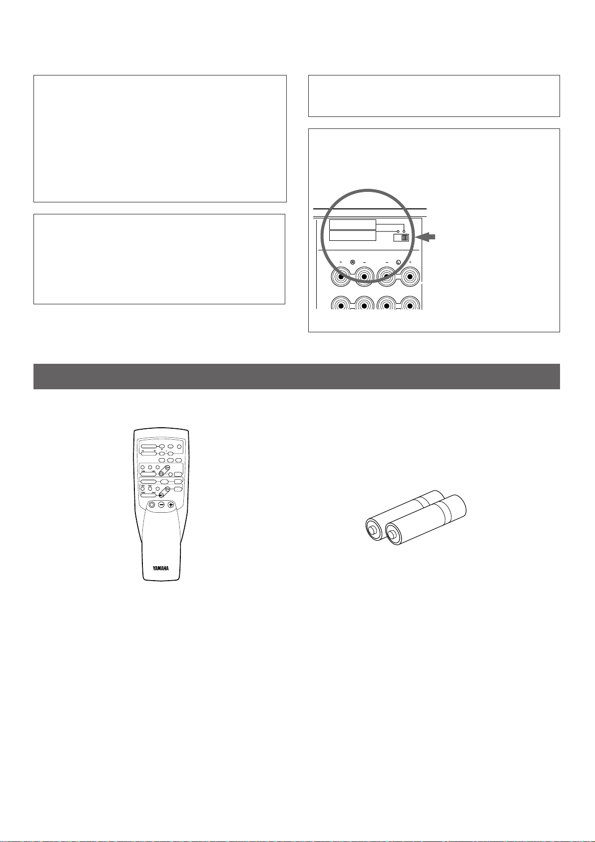
SUPPLIED ACCESSORIES
REC/PAUSE
DIR BDIR A
PLAY
DISC
2CH/6CH VOLUME
PLAY
PRESET
A/B/C/D/E
–+
TIME/
LEVEL
TEST
EFFECT
PROGRAM
PROLOGIC
ENHANCED
–+
TAPE
A/B
ON/OFF
TUNER L2
CD L1
DELAY/CENTER
/REAR/SWFR
DVD/LD
VCR
TV/DBS
Remote Control Transmitter
Batteries (size AA, R6, UM-3)
After unpacking, check that the following parts are included.
Page 5

5
English
●
Center and Rear Channel Power Amplifier
Center: 60W (8Ω) RMS Output Power,
0.04% THD, 20 – 20.000 Hz
Rear: 60W + 60W (8Ω) RMS Output
Power, 0.04% THD, 20 – 20.000
Hz
●
Digital Sound Field Processor
●
Dolby Pro Logic Surround Decoder
●
Theater-like Sound Experience by the
Combination of Dolby Pro Logic and
YAMAHA DSP Technology (CINEMA DSP)
●
Automatic Input Balance Control for
Dolby Pro Logic Surround
●
Test Tone Generator for Easier Speaker
Balance Adjustment
●
3 Center Channel Modes
(NORMAL/WIDE/PHANTOM)
● Video Signal Input/Output Capability
● 6-Channel Discrete Input Terminals for
Connecting with a Dolby Digital (AC-3)
Decoder
● 6-Channel Input Terminals to Input Audio
Signals from Your Existing Amplifier or
Receiver
● Remote Control Capability
FEATURES
Battery installation
Battery replacement
If you find that the remote control transmitter must be used
closer to the main unit, the batteries are weak. Replace both
batteries with new ones.
Notes
●
Use only AA, R6, UM-3 batteries for replacement.
●
Be sure the polarities are correct. (See the illustration inside
the battery compartment.)
●
Remove the batteries if the remote control transmitter will
not be used for an extended period of time.
●
If batteries leak, dispose of them immediately. Avoid
touching the leaked material or letting it come in contact with
clothing, etc. Clean the battery compartment thoroughly
before installing new batteries.
Remote control transmitter operation range
Notes
●
There should be no large obstacles between the remote
control transmitter and the main unit.
●
If the remote control sensor is directly illuminated by strong
lighting (especially an inverter type of fluorescent lamp etc.),
it might cause the remote control transmitter not to work
correctly. In this case, reposition the main unit to avoid direct
lighting.
1
3
2
l6
20
28
40
60
l2
8
4
2
0
–dB
30°
30°
Remote control
sensor
Within approximately
6 m (19.7 feet)
NOTES ABOUT THE REMOTE CONTROL TRANSMITTER
Page 6

6
PROFILE OF THIS UNIT
You are the proud owner of a Yamaha AV processor/amplifier –an extremely sophisticated audio component. The Digital Sound
Field Processor (DSP) built into this unit takes advantage of Yamaha’s undisputed leadership in the field of digital audio processing
to bring you a whole new world of listening experiences. Follow the instructions in this manual carefully when setting up your system,
and this unit will sonically transform your room into a wide range of listening environments –movie theater, concert hall, and so on.
In addition, you get incredible realism from sources encoded with Dolby Surround using the built-in Dolby Pro Logic Surround
Decoder.
Please read this operation manual carefully and store it in a safe place for later reference.
Digital Sound Field Processing
What is it that makes live music so good? Today’s advanced
sound reproduction technology lets you get extremely close to
the sound of a live performance, but chances are you’ll still
notice something missing: the acoustic environment of the live
concert hall. Extensive research into the exact nature of the
sonic reflections that create the ambience of a large hall has
made it possible for Yamaha engineers to bring you this same
sound in your own listening room, so you’ll feel all the sound of
a live concert.
Furthermore, our technicians, armed with sophisticated
measuring equipment, have even made it possible to capture
the acoustics of a variety of venues such as an actual concert
hall, theater, etc. to allow you to accurately recreate one of
several actual live performance environments, all in your own
home.
Dolby Pro Logic Surround
This unit employs a Dolby Pro Logic Surround decoder similar
to professional Dolby Stereo decoders used in many movie
theaters. By using the Dolby Pro Logic Surround decoder, you
can experience the dramatic realism and impact of Dolby
Surround movie theater sound in your own home. Dolby Pro
Logic employs a four channel five speaker system. The Pro
Logic Surround system divides the input signal into four levels:
the left and right main channels, the center channel (used for
dialog), and the rear surround sound channels (used for sound
effects, background noise, and other ambient noises). The
center channel allows listeners seated in even less-than-ideal
positions to hear the dialog originating from the action on the
screen while experiencing good stereo imaging.
Dolby Surround is encoded on the sound track of pre-recorded
video tapes, laser discs, and some TV/cable broadcasts. When
you play a source encoded with Dolby Surround on this unit,
the Dolby Pro Logic Surround decoder decodes the signal and
distributes the surround-sound effects.
This Dolby Pro Logic Surround Decoder employs a digital
signal processing system. This system improves the stability of
sound at each channel and minimizes crosstalk between
channels, so that positioning of sounds around the room is
more accurate compared with conventional analog signal
processing systems.
In addition, this unit features a built-in automatic input balance
control. This always assures you the best performance without
manual adjustment.
Manufactured under license from Dolby Laboratories Licensing
Corporation. “Dolby”, “AC-3”, “Pro Logic”, and the double-D
symbol are trademarks of Dolby Laboratories Licensing
Corporation.
Dolby Pro Logic Surround + DSP
Dolby Surround sound system shows its full ability in a large
movie theater, because movie sounds are originally designed
to be reproduced in a large movie theater using many
speakers. It is difficult to create a sound environment similar to
that of a movie theater in your listening room, because the
room size, materials of inside walls, the number of speakers,
etc. of your listening room is much different from those of a
movie theater.
Yamaha DSP technology made it possible to present you with
nearly the same sound experience as that of a large movie
theater in your listening room by compensating for lack of
presence and dynamics in your listening room with its original
digital sound fields combined with Dolby Surround sound field.
The combination of Dolby Pro Logic Surround and DSP is used
on the sound field program “ PRO LOGIC ENHANCED”.
The YAMAHA “CINEMA DSP” logo indicates these programs are
created by the combination of Dolby Pro Logic and YAMAHA
DSP technology.
CINEMA DSP
Page 7

7
English
SPEAKER CONFIGURATION
5-Speaker Configuration
This configuration is the most effective and recommended one.
In this configuration, the center speaker is necessary as well as
the rear speakers. If the program DOLBY PRO LOGIC or
DOLBY PRO LOGIC ENHANCED is selected, conversations
will be output from the center speaker and the ambience will be
excellent.
• Set the center channel mode to the “NORMAL” or “WIDE”
position. (For details, refer to page 18.)
4-Speaker Configuration
The center speaker is not used in this configuration. If the
program DOLBY PRO LOGIC or DOLBY PRO LOGIC
ENHANCED is selected, the center sound is output from the
left and the right main speakers. However, the sound effect of
other programs can be the same as that of the 5-speaker
configuration.
• Be sure to set the center channel mode to the “PHANTOM”
position. (For details, refer to page 18.)
SPEAKER SETUP
SPEAKERS TO BE USED
This unit is designed to provide the best sound-field quality with a 5-speaker configuration. The most effective speakers to use with
this unit are main speakers, rear speakers and a center speaker. You may omit the center speaker. (Refer to the “4-Speaker
Configuration” shown below.)
The main speakers are used for the main source sound plus the effect sounds. They will probably be the speakers from your present
stereo system. The rear speakers are used for the effect and surround sounds, and the center speaker is for the center sounds
(dialog etc.) within programs encoded with Dolby Surround. The center speaker needs to be equal in power to the main speakers,
although the rear speakers should not be equal. However, all the speakers should have high enough power handling to accept the
maximum output of this unit.
SPEAKER PLACEMENT
The recommended speaker configuration, the 5-speaker configuration, will require two speaker pairs: main speakers (your normal
stereo speakers), and rear speakers, plus a center speaker. When you place these speakers, refer to the following.
Main: In normal position. (The position of your present
stereo speaker system.)
Rear: Behind your listening position, facing slightly inward.
Nearly six feet (approx. 1.8 m) up from the floor.
Center: Precisely between the main speakers. (To avoid
interference with TV sets, use a magnetically shielded
speaker.)
Front L Center Front R
Dialogue
Surround sound
Dialogue
Surround sound
Rear L
Rear R
Front L Front R
Dialogue
Surround sound
Dialogue
Surround sound
Rear L Rear R
Front R
Center
Front L
TV set
Rear R
Rear L
Main L
Main R
Main L
Main R
Main L
Main R
Page 8

8
CONNECTIONS
REAR PANEL PARTS AND THEIR FUNCTIONS
MONITOR
OUT
DVD/LD TV/DBS
IN OUT
VCR
VIDEO SIGNAL
CD
(LINE 1)
TAPE
( MD )
DVD/LD TV/DBS
VCR
TAPEPBREC
OUT
IN OUT
AUDIO SIGNAL
1
3 4
MAIN
TUNER
(LINE 2)
2
MAINS
SPEAKERS
OUTPUT
INPUT OUTPUT
l0 dB 0 dB
l
MAIN
LEVEL
SINGLE:8ΩMIN./SPEAKER
DUAL:4ΩMIN./SPEAKER
8ΩMIN./SPEAKER
CENTER
REAR
SINGLE:4ΩMIN./SPEAKER
DUAL:2ΩMIN./SPEAKER
6ΩMIN./SPEAKER
CENTER
REAR
IMPEDANCE SELECTOR
REAR CENTER
SUB
WOOFER
DUAL
(SURROUND)
DUAL
CAUTION
SEE INSTRUCTION MANUAL FOR CORRECT SETTING.
DUAL DUAL
SINGLE
REAR
CENTER
I00W MAX.
SWITCHED
AC OUTLET
6CH DISCRETE
INPUT
REARCENTERMAIN
SUB
WOOFER
(SURROUND) (SURROUND)
REARCENTERMAIN
SUB
WOOFER
INPUT
from
AMP/RECEIVER
PREOUT
1
890ABCD
23 4 567
1 6CH DISCRETE INPUT terminals
Connect a Dolby Digital (AC-3) Decoder to these terminals.
6-channels (left main, right main, center, left rear surround,
right rear surround and subwoofer) of discrete audio signals
with the Dolby Digital (AC-3) decoded are input to these
terminals from the decoder.
2 INPUT (from AMP/RECEIVER PREOUT) terminals
These are additional 6-channel audio signal input terminals (for
left main, right main, center, left rear surround, right rear
surround and subwoofer channels) available for inputting
signals from your existing amplifier, receiver, sound processor,
etc. to this unit.
To listen to a sound by reproducing signals input to these
terminals from the external amplifier etc., be sure to set the
PROCESSOR SELECTOR switch on the front panel to the
“EXTERNAL” position. By doing so, the signals input to these
terminals are sent to the corresponding SPEAKERS terminals
and OUTPUT terminals of this unit bypassing any circuit in this
unit. So, volume, tone, etc. must be controlled on the external
amplifier.
3 MAIN OUTPUT terminals
Main-channel line output. Connect these to input terminals of
external stereo power amplifier (MAIN IN or equivalent
terminals of integrated amplifier or receiver) driving the main
speakers.
4 IMPEDANCE SELECTOR switch
Select the position whose requirements your speaker system
meets.
Be sure to switch this only when the power of this unit is turned
off.
(Right position)
Center: If you use one center speaker, the impedance of
the speaker must be 8Ω or higher.
If you use two center speakers, the impedance of
each speaker must be 4Ω or higher.
Rear: The impedance of each speaker must be 8Ωor
higher.
(Left position)
Center: If you use one center speaker, the impedance of
the speaker must be 4Ω or higher.
If you use two center speakers, the impedance of
each speaker must be 2Ω or higher.
Rear: The impedance of each speaker must be 6Ωor
higher.
WARNING
Do not change the IMPEDANCE SELECTOR switch
setting while the power to this unit is on, otherwise this
unit may be damaged.
INTERNAL
EXTERNAL
PROCESSOR
SELECTOR
(Europe model)
Page 9

9
English
5 MAIN LEVEL switch <U.K. and Europe models only>
Normally set to “0 dB”. If desired, you can decrease the output
level at the MAIN OUTPUT terminals by 10 dB by setting this
switch to “–10 dB”.
6 AC OUTLET (UNSWITCHED)
The power cord of any audio/video unit can be connected to
this outlet.
The power to this outlet is not controlled by this unit’s POWER
switch. This outlet will supply power to the connected unit even
if this unit is turned off.
The maximum power that can be connected to this outlet is
100 watts.
7 AC power cord
After all connections are completed, connect this into a wall AC
outlet.
8 AUDIO SIGNAL connection terminals (for audio source
equipment)
Connect the inputs and/or outputs of your audio equipment.
9 AUDIO/VIDEO SIGNAL connection terminals (for video
source equipment)
Connect the audio and video inputs and/or outputs of your
video equipment.
0 REAR SPEAKERS terminals
When using the built-in rear-channel amplifier, connect the rear
speakers here.
A CENTER SPEAKERS terminals
When using the built-in center-channel amplifier, connect one
or two center speakers here.
B REAR (SURROUND) OUTPUT terminals
These terminals are for rear channel line output. There is no
connection to these terminals when you use the built-in
amplifier.
However, if you drive rear speakers with an external stereo
power amplifier, connect the input terminals of the external
amplifier (MAIN IN or AUX terminals of a power amplifier or an
integrated amplifier) to these terminals.
Note
Output level of signals from the MAIN, REAR, CENTER and
SUBWOOFER OUTPUT terminals are adjusted by the use of
VOLUME control on the front panel or VOLUME keys on the
remote control transmitter.
C CENTER OUTPUT terminals
These terminals are for center channel line output. There is no
connection to these terminals when you use the built-in
amplifier.
However, if you drive a center speaker with an external power
amplifier, connect the input terminal of the external amplifier
driving a center speaker to one of these terminals.
If you drive two center speakers with external amplifiers,
connect the input terminal of the external amplifier driving
another center speaker to the other terminal.
D SUBWOOFER OUTPUT terminals
You may wish to add a subwoofer to reinforce the bass
frequencies.
These terminals are line level outputs for connecting with the
amplifier(s) driving subwoofer(s).
When the input signals to this unit are in normal 2-channel
stereo, these terminals output only frequencies below 150 Hz
(200 Hz for General model only) from the main and center
channels. When signals decoded with the Dolby Digital (AC-3)
are input to this unit and are selected as the input source,
these terminals output signals from the subwoofer channel.
Page 10
10
MONITOR
OUT
DVD/LD TV/DBS
IN OUT
VCR
VIDEO SIGNAL
CD
(LINE 1)
TAPE
( MD )
DVD/LD TV/DBS
VCR
TAPEPBREC
OUT
IN OUT
AUDIO SIGNAL
1 3 4
MAIN
TUNER
(LINE 2)
2
(SURROUND)
REAR
CENTERMAIN
SUB
WOOFER
INPUT
from
AMP/RECEIVER
PREOUT
OUTPUT OUTPUT
l0 dB 0 dB
l
MAIN
LEVEL
6CH DISCRETE
INPUT
REAR
CENTERMAIN
SUB
WOOFER
(SURROUND)
I00W MAX.
SWITCHED
AC OUTLET
MAINS
INPUT
OUTPUT
OUTPUT
LINE OUT
LINE IN
VIDEO OUT
AUDIO OUT
AUDIO OUT
AUDIO IN
VIDEO IN
VIDEO OUT
AUDIO OUT
VIDEO OUT
MAIN IN
VIDEO IN
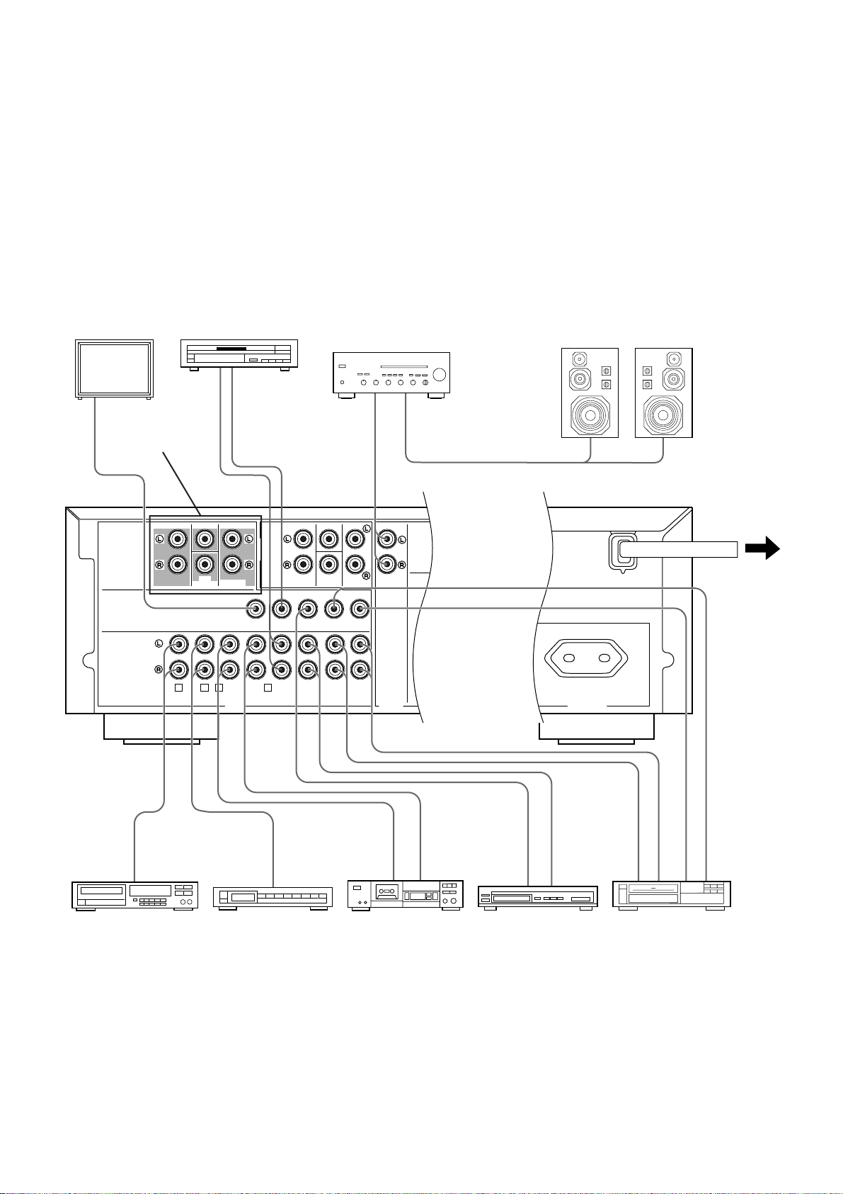
EXAMPLES OF BASIC CONNECTIONS
Never plug in this unit and other components until all connections are completed.
Note
When making connections between this unit and other components, be sure all connections are made correctly, that is to say L (left)
to L, R (right) to R, “+” to “+” and “–” to “–”. Also, refer to the owner’s manual for each component to be connected to this unit.
* If you have YAMAHA components numbered as
1, 2, 3, etc. on the rear panel, connections can be made easily by making sure
to connect the output (or input) terminals of each component to the same-numbered terminals of this unit.
1
When this unit is used as a main controller
(Europe model)
To AC outlet
Monitor TV
Amplifier
(for driving main speakers)
Video cassette recorderTV/Satellite tuner
Tape deck,
MD recorder, etc.
CD player
LD player etc.
Main speakers
Left
Right
Tuner
Notes
●
If you select this connecting way, the PROCESSOR
SELECTOR switch on the front panel of this unit must be
set to the “INTERNAL” position.
●
For speaker connections, see page 12 – 13.
See page 11.
Page 11

11
English
Connecting with a Dolby Digital (AC-3) Decoder
If you have a Dolby Digital (AC-3) Decoder unit or an LD player etc. which incorporates a Dolby Digital (AC-3) Decoder, its discrete
outputs can be connected to this unit.
Notes
• The laserdisc player (or another unit) must be also
connected to the DVD/LD (or TV/DBS) AUDIO SIGNAL
INPUT terminals of this unit for playing a source with the
Dolby Pro Logic Surround decoded or in normal stereo (or
monaural).
• The discrete signals input to this unit cannot be recorded by
a tape deck, MD recorder or VCR. To record a source played
on the laserdisc player (or another unit), it must be
connected to the DVD/LD (or TV/DBS) AUDIO/VIDEO
SIGNAL INPUT terminals of this unit.
• If you made no connection to the SUBWOOFER input
terminal of this unit or you will not use a subwoofer, you
should make a setting for distributing signals at the LFE
channel to the right and left MAIN output terminals on the
Dolby Digital (AC-3) Decoder unit.
(For details, refer to the owner’s manual for the Dolby Digital
(AC-3) Decoder unit.
MONITOR
OUT
DVD/LD TV/DBS
IN OUT
VCR
VIDEO SIGNAL
CD
(LINE 1)
TAPE
( MD )
DVD/LD TV/DBS
VCR
TAPEPBREC
OUT
IN OUT
AUDIO SIGNAL
1 3 4
TUNER
(LINE 2)
2
(SURROUND)
REAR
CENTERMAIN
SUB
WOOFER
INPUT
from
AMP/RECEIVER
PREOUT
INPUT
6CH DISCRETE
INPUT
REAR
CENTERMAIN
SUB
WOOFER
(SURROUND)
AC-3 RF
OUT
AC-3 RF
IN
DIGITAL
IN
DIGITAL
OUT
VIDEO OUT
AUDIO OUT
6CH DISCRETE OUTPUT
CENTER SURROUND
SUB
WOOFER
MAIN
Dolby Digital (AC-3) Decoder unit
RF Demodulator
Laserdisc player with AC-3 RF output or
another unit with AC-3 RF output
Page 12

12
Red: positive (+)
Black: negative (–)
➀
Unscrew the knob.
➁
Insert the bare wire.
[Remove approx. 5mm
(1/4”) insulation from
the speaker wires.]
➂
Tighten the knob and
secure the wire.
<General model only>
Banana Plug connections are also possible. Simply insert the
Banana Plug connector into the corresponding terminal.
1
2
3
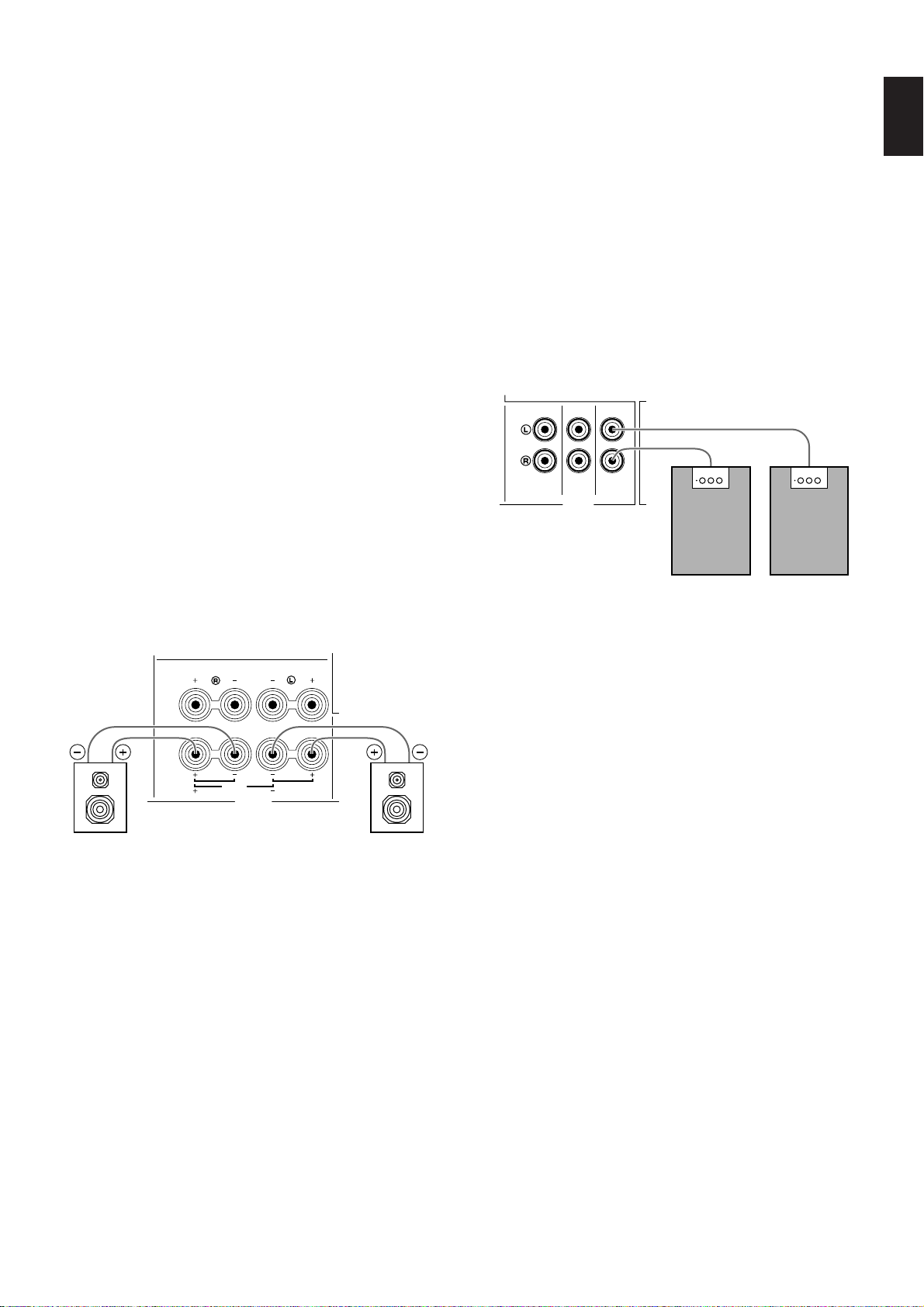
How to Connect to the REAR and CENTER SPEAKERS terminals
Connect the SPEAKERS terminals to your speakers with wire of the proper gauge, cut as short as possible. If the connections are
faulty, no sound will be heard from the speakers. Make sure that the polarity of the speaker wires is correct, that is the + and –
markings are observed. If these wires are reversed, the sound will be unnatural and lack bass.
Caution
Do not let the bare speaker wires touch each other and do not let them touch any metal part of this unit. This could damage
this unit and/or speakers.
Note
Use speakers with the specified impedance shown on the rear of this unit.
CONNECTING SPEAKERS
MAIN
SPEAKERSOUTPUT OUTPUT
l0 dB 0 dB
l
MAIN
LEVEL
SINGLE:8ΩMIN./SPEAKER
DUAL
:4ΩMIN./SPEAKER
8ΩMIN./SPEAKER
CENTER
REAR
SINGLE:4ΩMIN./SPEAKER
DUAL
:2ΩMIN./SPEAKER
6ΩMIN./SPEAKER
CENTER
REAR
IMPEDANCE SELECTOR
REAR CENTER
SUB
WOOFER
DUAL
(SURROUND)
DUAL
CAUTION
SEE INSTRUCTION MANUAL FOR CORRECT SETTING.
DUAL DUAL
SINGLE
REAR
CENTER
Amplifier
(for driving main speakers)
Center speakerRear speakers
Main speakers
Subwoofer system
(Europe model)
Left Right
LeftRight
Page 13
13
English
On main speaker connection
This unit is not equipped with amplifiers for driving main
speakers, so connect an external amplifier (power amplifier,
integrated amplifier, receiver, etc.) for driving main speakers to
this unit.
Connect the MAIN OUTPUT terminals of this unit to the MAIN
IN (or equivalent) terminals of the external amplifier, and
connect the main speakers to the speaker terminals of the
external amplifier.
Notes
●
If the external amplifier does not have the MAIN IN (or
equivalent) terminals, this unit can be connected to the AUX
(or TAPE PB) input terminals of the amplifier. If you did so,
make sure to select the “AUX” (or “TAPE”) input source
position and do not change to another input source
selection.
●
To obtain the best performance of this unit, set the volume
control on the external amplifier to about the halfway
position between the min. and max.
On center speaker connection
One or two center speakers can be connected to this unit. If
you cannot place the center speaker on or under the TV, it is
recommended to use two center speakers and place them on
both sides of the TV to orient the center sound at the center
position. For connecting two center speakers, follow the
method shown below.
On subwoofer connection
You may wish to add a subwoofer to reinforce the bass
frequencies.
If you use one subwoofer, connect either of the SUBWOOFER
OUTPUT terminals to the INPUT terminal of the subwoofer
amplifier, and connect the speaker terminals of the subwoofer
amplifier to the subwoofer.
If you wish to obtain more presence in your listening room, the
use of two subwoofers is recommended. To connect two
subwoofers to this unit, connect one SUBWOOFER OUTPUT
terminal to the INPUT terminal of the amplifier driving a
subwoofer, and the other SUBWOOFER OUTPUT terminal to
the INPUT terminal of the amplifier driving the other subwoofer,
and then connect each subwoofer to the corresponding
amplifier.
With some subwoofers, including the Yamaha Active Servo
Processing Subwoofer System, the amplifier and subwoofer
are in the same unit.
DUAL DUAL
SINGLE
REAR
CENTER
SPEAKERS
CAUTION
SEE INSTRUCTION MANUAL FOR CORRECT SETTING.
OUTPUT
REAR CENTER
SUB
WOOFER
DUAL
(SURROUND)
DUAL
Subwoofer
system
Subwoofer
system
Center speaker Center speaker
Page 14

14
2
When connecting with your existing integrated amplifier or receiver
which cannot receive signals with the Dolby Digital (AC-3) decoded
(This diagram shows this unit is connected with the Yamaha DSP-A2070 which is equipped with the digital sound field
processor, the Dolby Pro Logic Surround Decoder and seven-speaker driving amplifiers.)
MONITOR
OUT
DVD/LD TV/DBS
IN OUT
VCR
VIDEO SIGNAL
CD
(LINE 1)
TAPE
( MD )
DVD/LD TV/DBS
VCR
TAPEPBREC
OUT
IN OUT
AUDIO SIGNAL
1
3 4
MAIN
TUNER
(LINE 2)
2
(SURROUND)
REARCENTERMAIN
SUB
WOOFER
INPUT
from
AMP/RECEIVER
PREOUT
MAINS
SPEAKERS
OUTPUT
INPUT OUTPUT
l0 dB 0 dB
l
MAIN
LEVEL
SINGLE:8ΩMIN./SPEAKER
DUAL:4ΩMIN./SPEAKER
8ΩMIN./SPEAKER
CENTER
REAR
SINGLE:4ΩMIN./SPEAKER
DUAL:2ΩMIN./SPEAKER
6ΩMIN./SPEAKER
CENTER
REAR
IMPEDANCE SELECTOR
REAR CENTER
SUB
WOOFER
DUAL
(SURROUND)
DUAL
CAUTION
SEE INSTRUCTION MANUAL FOR CORRECT SETTING.
DUAL DUAL
SINGLE
REAR
CENTER
I00W MAX.
SWITCHED
AC OUTLET
6CH DISCRETE
INPUT
REARCENTERMAIN
SUB
WOOFER
(SURROUND)
CENTER IN
MAIN IN
REAR OUT
CENTER OUT
LOW PASS
MAIN OUT
AUDIO OUT
VIDEO OUT
AC-3 RF OUT
AC-3 RF IN
Main speaker
Front effect speaker
Center speaker
Rear speakers
Subwoofer
System
Front effect speaker
Main speaker
Dolby Digital (AC-3) Decoder
RF demodulator
(YAMAHA APD-1 etc.)
LD player etc.
Amplifier or
receiver
To AC
outlet
Audio/Video equipment
(Europe model)
Left
Left
Right
Right
LeftRight
Notes
●
For the connections to this unit’s 6CH DISCRETE INPUT
terminals, refer to page 11.
●
For the connections of rear speakers and subwoofer(s) to
this unit, refer to page 12 – 13.
●
If you select this connecting way, the PROCESSOR
SELECTOR switch on the front panel must be normally set
to the “EXTERNAL” position. When you will play a source
on the LD player etc. (connected to this unit) with the Dolby
Digital (AC-3) decoded, set the PROCESSOR SELECTOR
switch to the “INTERNAL” position.
Page 15

15
English
1 POWER switch
Press this switch to switch the power on. Press it again to
switch the power off.
2 Remote control sensor
Receives signals from the remote control transmitter.
3 Display panel
Shows various information. (Refer to page 17 for details.)
4 Input selector buttons
Select a program source to listen to or watch. When a button is
pressed, the name of selected source appears on the display.
5 2CH/6CH selector button
When the TV/DBS or DVD/LD input source is selected,
pressing this button switches the input signals between 2
channel stereo signals and 6 channel discrete signals. When
switched to “6CH”, signals from the Dolby Digital (AC-3)
Decoder etc. connected to the 6CH DISCRETE INPUT
terminals of this unit are selected as the input signals.
6 VOLUME control
Used to raise or lower the volume level.
7 EFFECT button
Switches on/off the digital sound field processor (including the
Dolby Pro Logic Surround decoder).
8 DSP program selector buttons
Select a DSP program. When a button is pressed, the name of
selected program lights up on the display.
9 CENTER MODE button
Selects a center channel output mode (NORMAL, WIDE or
PHANTOM). (For details, refer to page 18.)
0 DELAY/CENTER/REAR/SWFR and TIME/LEVEL +/–
buttons
Adjust the delay time (DELAY), the center channel output level
(CENTER), the rear channel output level (REAR) and the
output level to the SUBWOOFER OUTPUT terminal (SWFR).
Select the item which you want to adjust by pressing the
DELAY/CENTER/REAR/SWFR button and adjust its time or
level by pressing the TIME/LEVEL +/– button.
A PROCESSOR SELECTOR switch
When you play a source on an audio/video unit connected to
this unit, set this switch to the “INTERNAL” position. When you
listen to sound reproducing signals input to the INPUT (from
AMP/RECEIVER PREOUT) terminals on the rear panel from
the external amplifier etc., set this switch to the “EXTERNAL”
position.
CONTROLS AND THEIR FUNCTIONS
FRONT PANEL
NATURAL SOUND AV PROCESSOR/AMPLIFIER
DSP–E492
CINEMA DSP
POWER
VOLUME
l6
20
28
40
60
l2
8
4
2
0
–dB
DELAY/CENTER
/REAR/SWFR
CENTER
MODE
TIME/LEVEL
INTERNAL
EXTERNAL
PRESET
kHz
MHz
MEMORY AUTO PTY HOLD
SLEEP
TAPE MONITOR
STEREO
ms dB
PRO LOGIC
ENHANCED
CONCERT
VIDEO
MONO
MOVIE
STADIUM
DISCO
ROCK CONCERT
CONCERT HALL
VCR DVD/LD
2CH
/
6CH
TV/DBS
TAPE (MD)
MONITOR
TUNER
(LINE 2)
CD
(LINE 1)
NORMAL
WIDE
PHANTOM
EFFECT OFF
PS
EON
INFO AFFAIRS SPORT
NEWS
RT CTPTY
0
20
l00
40 60
EFFECT
PRO LOGIC
ENHANCED MONO MOVIE STADIUM
PROCESSOR
SELECTOR
DISCO
ROCK CONCERT CONCERT HALLCONCERT VIDEO
1
78 9 A
2456
0
3
Page 16

16
For Control of This Unit
1 DELAY/CENTER/REAR/SWFR and TIME/LEVEL +/–
keys
Adjust the delay time (DELAY), the center channel output level
(CENTER), the rear channel output level (REAR) and the
output level to the SUBWOOFER OUTPUT terminal (SWFR).
Select the item which you want to adjust by pressing the
DELAY/CENTER/REAR/SWFR key and adjust its time or level
by pressing the TIME/LEVEL +/– key.
2 2CH/6CH selector key
When the TV/DBS or DVD/LD input source is selected,
pressing this key switches the input signals between 2 channel
stereo signals and 6 channel discrete signals. When switched
to “6CH”, signals from the Dolby Digital (AC-3) Decoder etc.
connected to the 6CH DISCRETE INPUT terminals of this unit
are selected as the input signals.
3 VOLUME +/– keys
Turns the volume level up/down.
4 Input selector keys
Selects input source.
5 Program selector keys
PROGRAM:
When the built-in digital sound field processor (including the
Dolby Pro Logic Surround decoder) is on, this key changes the
currently selected DSP program whenever the right or left side
of this key is pressed.
PROLOGIC:
Directly selects the PRO LOGIC program.
ENHANCED:
Directly selects the PRO LOGIC ENHANCED program.
6 EFFECT ON/OFF key
Switches on/off the digital sound field processor (including the
Dolby Pro Logic Surround decoder).
7 TEST key
Used for speaker balance adjustment. (For details, refer to
page 18 – 19.)
REMOTE CONTROL TRANSMITTER
The remote control transmitter provided with this unit is designed to control all the most commonly used functions of this unit. If the
CD player, tuner and tape deck connected to this unit are YAMAHA components designed for remote control compatibility, then this
remote control transmitter will also control various functions of each component.
REC/PAUSE
DIR BDIR A
PLAY
DISC
2CH/6CH VOLUME
PLAY
PRESET
A/B/C/D/E
–+
TIME/
LEVEL
TEST
EFFECT
PROGRAM
PROLOGIC
ENHANCED
–+
TAPE
A/B
ON/OFF
TUNER L2
CD L1
DELAY/CENTER
/REAR/SWFR
DVD/LD
VCR
TV/DBS
2
2
3
6
7
4
5
3
1
1
Page 17
17
English
TAPE MON
ms dB
PRO LOGIC
ENHANCED
CONCERT
VIDEO
MONO
MOVIE
STADIUM
DISCO
ROCK CONCERT
CONCERT HALL
NORM
WIDE
PHANTOM
EFFECT OFF
1
23
4
5
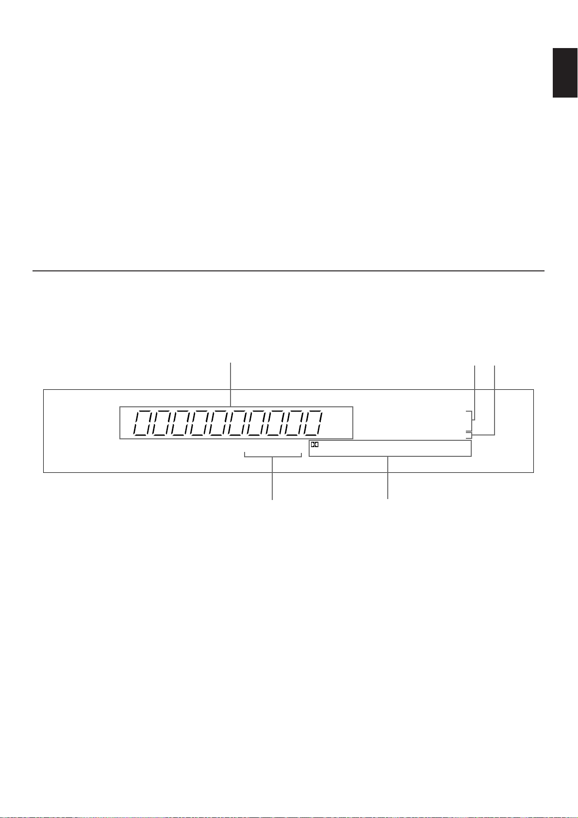
1 Multi-information display
Displays various information, for example name of selected
DSP program and name of selected input source.
2 Center channel mode indicators
The name of a selected center channel mode lights up only
when a program which uses the Dolby Pro Logic Surround
decoder is selected.
3 EFFECT OFF indicator RX-V592RDS only
Lights up if neither the digital sound field processor nor the
Dolby Pro Logic Surround decoder is on. In this state, sound
output is 2-channel stereo.
4 TAPE MON indicator
Lights up when the tape deck (or MD recorder etc.) is selected
as the input source by pressing the TAPE (MD) MONITOR
button.
5 DSP program indicators
The name of a selected DSP program lights up when the builtin digital sound field processor and/or the Dolby Pro Logic
Surround decoder is on.
DISPLAY PANEL
For Other Component Control
Identify the remote control transmitter keys with your
component’s keys. If these keys are identical, their functions
will be the same. On each key function, refer to the
corresponding instruction on your component’s manual.
1 Tape deck keys
Controls tape deck.
* DIR A, B and A/B are applicable only to double
cassette tape deck.
* For a single cassette deck with automatic reverse
function, pressing DIR A will reverse the direction of
tape running.
2 Tuner keys
Controls tuner.
+: Selects higher preset station number.
–: Selects lower preset station number.
A/B/C/D/E: Selects the group (A – E) of preset station
numbers.
3 CD player keys
Controls compact disc player.
* DISC is applicable only to compact disc changer.
Page 18

18
1
Set to the “∞” position.
2 Turn on the power of this unit and the external amplifier
etc.
3 Set the balance control, tone controls, etc. on the
external amplifier to the “flat” position.
4
5 Select the center channel output mode suitable for your
speaker configuration.
(Refer to “SPEAKER CONFIGURATION” on page 7.)
On the feature of each mode, refer to the “Note” shown
below.
Note
In step 5, when you select a center channel output mode, note
the following.
For 5-speaker configuration)
NORMAL: Select this mode when you use a center speaker
that is smaller than the main speakers. In this
mode, the bass tone will be output from the main
speakers.
WIDE: Select this mode when you use the center speaker
approximately same sized as the main speakers.
For 4-speaker configuration)
PHANTOM: Select this mode when you do not use the center
speaker. The center sound will be output from the
left and right main speakers.
CENTER
MODE
NORMAL
WIDE
PHANTOM
SPEAKER BALANCE ADJUSTMENT
This procedure lets you adjust the sound output level balance between the main, center, and rear speakers using the built-in test
tone generator. When this adjustment is performed, the sound output level heard at the listening position will be the same from
each speaker. This is important for the best performance of the digital sound field processor and the Dolby Pro Logic Surround
decoder.
The adjustment of each speaker output level should be done at your listening position with the remote control transmitter.
Otherwise, the result may not be satisfactory.
Note
If this unit is connected with a Dolby Digital (AC-3) Decoder and/or an amplifier (or receiver) equipped with the Dolby Pro Logic
Decoder or the digital sound field processor, also make an output balance adjustment using the test tone on each unit.
l6
20
28
40
60
l2
8
4
2
0
–dB
VOLUME
POWER
REC/PAUSE
DIR BDIR A
PLAY
DISC
2CH/6CH VOLUME
PLAY
PRESET
A/B/C/D/E
–+
TIME/
LEVEL
TEST
EFFECT
PROGRAM
PROLOGIC
ENHANCED
–+
TAPE
A/B
ON/OFF
TUNER L2
CD L1
DELAY/CENTER
/REAR/SWFR
DVD/LD
VCR
TV/DBS
1
2
NATURAL SOUND AV PROCESSOR/AMPLIFIER
DSP–E492
CINEMA DSP
POWER
VOLUME
l6
20
28
40
60
l2
8
4
2
0
–dB
DELAY/
CENTER/REAR
CENTER
MODE
TIME/LEVEL
INTERNAL
EXTERNAL
PRESET
kHz
MHz
MEMORY AUTO PTY HOLD
SLEEP
TAPE MONITOR
STEREO
ms dB
PRO LOGIC
ENHANCED
CONCERT
VIDEO
MONO
MOVIE
STADIUM
DISCO
ROCK CONCERT
CONCERT HALL
VCR DVD/LD
2CH
/
6CH
TV/DBS
TAPE (MD)
MONITOR
TUNER
(LINE 2)CD(LINE 1)
NORMAL
WIDE
PHANTOM
EFFECT OFF
PS
EON
INFO AFFAIRS SPORT
NEWS
RT CTPTY
0
20
l00
40 60
EFFECT
PRO LOGIC
ENHANCED MONO MOVIE STADIUM
PROCESSOR
SELECTOR
DISCO
ROCK CONCERT CONCERT HALLCONCERT VIDEO
4, 8
TEST
5
6
7
Page 19

19
English
6 Turn up the volume.
You will hear a test tone (like pink noise) from the left main
speaker, then the center speaker, then the right main
speaker, and then the rear speakers, for about two seconds
each. The display changes as shown below.
* The test tone from the left rear speaker and the right
rear speaker will be heard at the same time.
7 Adjust the sound output levels of the center speaker
and the rear speakers so that they become almost as
same as that of the main speakers.
a) Press once or more so that “CENTER” or “REAR”
appears on the display.
* Select “CENTER” to adjust the output level of the
center speaker, and select “REAR” to adjust the
output level of the rear speakers.
b) Adjust its level.
* Pressing the + side raises and the – side lowers the
level.
8 Cancel the test tone.
Notes
●
Once you have completed these adjustments, you can
adjust whole sound level on your audio system by using
this unit’s VOLUME control (or the VOLUME keys on the
remote control transmitter) only.
●
You may also use the volume controls on the external
amplifiers etc. to achieve proper balance.
●
In step 7, if the center channel mode is in the “PHANTOM”
position, the sound output level of the center speaker
cannot be adjusted. This is because in this mode, the
center sound is automatically output from the left and right
main speakers.
<U.K. and Europe models only>
●
If there is insufficient sound output from the center and
rear speakers, you may decrease the main speaker output
level by setting the MAIN LEVEL switch on the rear panel
to “–10 dB”.
Main (L)
Main (R)
Center
Rear (L and R)
TIME/
LEVEL
–+
DELAY/CENTER
/REAR/SWFR
Disappears.
TEST
VOLUME
Page 20

20
1
Set to the “∞” position.
2 Turn on the power of this unit and other audio/video
units to be used.
3 Select the desired input source by using the input
selector buttons.
(For video sources, turn the TV/monitor ON.)
* The name of the selected input source will appear on
the display
4 Play the source.
5
Adjust to the desired output level.
6 If desired, use the digital sound field processor. (Refer
to page 24.)
Note
Confirm that the PROCESSOR SELECTOR switch is set to the
“INTERNAL” position. If it is set to the “EXTERNAL” position,
switch it to the “INTERNAL” position.
Notes on using the input selector buttons
●
Note that pressing on each input selector button selects the
source which is connected to the corresponding input
terminals on the rear panel.
●
The selection of TAPE (MD) MONITOR cannot be canceled
by pressing another input selector button. To cancel it, press
TAPE (MD) MONITOR again so that “TAPE MON”
disappears from the display.
When you select a button other than TAPE (MD)
MONITOR, make sure that “TAPE MON” is not illuminated
on the display.
●
If you select the input selector button for a video source
without canceling the selection of TAPE (MD) MONITOR,
the playback result will be the video image from the video
source and the sound from the audio tape (or MD etc.).
●
Once you play a video source, its video image will not be
interrupted even if the input selector button for an audio
source is selected.
BASIC OPERATIONS
TO PLAY A SOURCE
l6
20
28
40
60
l2
8
4
2
0
–dB
VOLUME
l6
20
28
40
60
l2
8
4
2
0
–dB
VOLUME
VCR DVD/LD
2CH
/
6CH
TV/DBS
TAPE (MD)
MONITOR
TUNER
(LINE 2)
CD
(LINE 1)
POWER
1, 5
2
NATURAL SOUND AV PROCESSOR/AMPLIFIER
DSP–E492
CINEMA DSP
POWER
VOLUME
l6
20
28
40
60
l2
8
4
2
0
–dB
DELAY/
CENTER/REAR
CENTER
MODE
TIME/LEVEL
INTERNAL
EXTERNAL
PRESET
kHz
MHz
MEMORY AUTO PTY HOLD
SLEEP
TAPE MONITOR
STEREO
ms dB
PRO LOGIC
ENHANCED
CONCERT
VIDEO
MONO
MOVIE
STADIUM
DISCO
ROCK CONCERT
CONCERT HALL
VCR DVD/LD
2CH
/
6CH
TV/DBS
TAPE (MD)
MONITOR
TUNER
(LINE 2)CD(LINE 1)
NORMAL
WIDE
PHANTOM
EFFECT OFF
PS
EON
INFO AFFAIRS SPORT
NEWS
RT CTPTY
0
20
l00
40 60
EFFECT
PRO LOGIC
ENHANCED MONO MOVIE STADIUM
PROCESSOR
SELECTOR
DISCO
ROCK CONCERT CONCERT HALLCONCERT VIDEO
3
To turn off the power
Press the POWER switch again.
Page 21

21
English
To listen to a decoded source using Dolby
Digital (AC-3) by reproducing the signals input
to the 6CH DISCRETE INPUT terminals of this
unit.
In step 3, select TV/DBS or DVD/LD, and then press the
2CH/6CH button so that “6ch” appears on the display.
Signals from the Dolby Digital (AC-3) Decoder etc. connected
to the 6CH DISCRETE INPUT terminals of this unit are
selected as the input signals.
To cancel it, press the 2CH/6CH button again or select another
input source.
Note for reproducing discrete signals with Dolby Digital
(AC-3) decoded:
1.
Your speaker system must include a center speaker.
2.
Your speaker system must include a subwoofer.
* Connect a subwoofer which has a built-in amplifier to one
of the SUBWOOFER OUTPUT terminals of this unit.
(One more subwoofer system can be connected to the
other SUBWOOFER OUTPUT terminal.)
* You can do without using a subwoofer. If you do so, you
should make a setting for distributing signals at the LFE
channel to the right and left MAIN output terminals on the
Dolby Digital (AC-3) Decoder.
For details, refer to the owner’s manual for the Dolby
Digital (AC-3) Decoder.
Notes
●
When you switch to the “6CH” mode, the built-in Digital
Sound Field processor will not work and adjustment of delay
time cannot be made.
●
Switching this unit to the “6CH” mode will input no signal to
this unit if there is no connection to the 6CH DISCRETE
INPUT terminals of this unit.
To listen to sound by reproducing signals input
to the INPUT (from AMP/RECEIVER PREOUT)
terminals on the rear panel from the external
amplifier etc.
1.
Adjust the volume to minimum on the external amplifier.
2. Turn on the power of the audio/video units (including this
unit) to be used.
3. Set the PROCESSOR SELECTOR switch on the front
panel of this unit to the “EXTERNAL” position.
4. Play the source.
5. Increase the volume to a desired listening level gradually
on the external amplifier etc.
6. If desired, adjust the balance, tone, etc. on the external
amplifier etc.
Note
When you will not use signals input to the INPUT (from
AMP/RECEIVER PREOUT) terminals on the rear panel, make
sure to set the PROCESSOR SELECTOR switch to the
“INTERNAL” position.
2CH/6CH
INTERNAL
EXTERNAL
PROCESSOR
SELECTOR
Page 22

22
1 Select the source to be recorded.
2 Play the source and then turn the VOLUME control up
to confirm the input source.
3 Begin recording on the tape deck (or MD recorder etc.)
or VCR connected to this unit.
4 If the tape deck (or MD recorder etc.) is used for
recording, you can monitor the sounds being recorded
by pressing TAPE (MD) MONITOR so that “TAPE
MON” lights up on the display.
Notes
●
In step 1, do not make an input source selection so that
“6ch” appears on the display. Signals input to this unit’s
6CH DISCRETE INPUT terminals cannot be recorded by a
tape deck, MD recorder or VCR.
●
The settings of DSP and the VOLUME control have no
effect on the material being recorded.
l6
20
28
40
60
l2
8
4
2
0
–dB
VOLUME
TO RECORD A SOURCE TO TAPE (OR MD)
2
NATURAL SOUND AV PROCESSOR/AMPLIFIER
DSP–E492
CINEMA DSP
POWER
VOLUME
l6
20
28
40
60
l2
8
4
2
0
–dB
DELAY/
CENTER/REAR
CENTER
MODE
TIME/LEVEL
INTERNAL
EXTERNAL
PRESET
kHz
MHz
MEMORY AUTO PTY HOLD
SLEEP
TAPE MONITOR
STEREO
ms dB
PRO LOGIC
ENHANCED
CONCERT
VIDEO
MONO
MOVIE
STADIUM
DISCO
ROCK CONCERT
CONCERT HALL
VCR DVD/LD
2CH
/
6CH
TV/DBS
TAPE (MD)
MONITOR
TUNER
(LINE 2)CD(LINE 1)
NORMAL
WIDE
PHANTOM
EFFECT OFF
PS
EON
INFO AFFAIRS SPORT
NEWS
RT CTPTY
0
20
l00
40 60
EFFECT
PRO LOGIC
ENHANCED MONO MOVIE STADIUM
PROCESSOR
SELECTOR
DISCO
ROCK CONCERT CONCERT HALLCONCERT VIDEO
1
4
VCR DVD/LD
2CH
/
6CH
TV/DBS
TAPE (MD)
MONITOR
TUNER
(LINE 2)
CD
(LINE 1)
VCR DVD/LD
2CH
/
6CH
TV/DBS
TAPE (MD)
MONITOR
TUNER
(LINE 2)
CD
(LINE 1)
Page 23

23
English
Brief Overview of Digital Sound Field Programs
The following list gives you a brief description of the sound fields produced by each of the DSP programs. Keep in mind that most of
these are precise digital recreations of actual acoustic environments. The data for these sound fields was recorded at actual
locations using sophisticated sound field measurement equipment.
Note
The channel level balance between the left and right rear effect speakers may vary depending on the sound field you are
listening to. This is due to the fact that most of these sound field recreations are actual acoustic environments.
PROGRAM FEATURE
This program is used for playback of sources encoded with Dolby Surround.
PRO LOGIC The application of a sophisticated digital signal processing system reduces crosstalk and directs or steers
the sound source more smoothly and precisely, as compared to conventional types.
This program is also used for playback of sources encoded with Dolby Surround.
PRO LOGIC
Enhancing the “Normal” Dolby Pro Logic, the DSP technology simulates the multi-surround speaker
ENHANCED
systems of a 35 mm movie theater. This effect creates a wide surround sound field, and expands the
sound stage with an improved presence image. This program is used for musical based movies, as well as
drama and comedy based movies.
CONCERT VIDEO
This program is effective for music videos and gives excellent depth and clarity for vocals. For opera, the
orchestra and stage are ideally recreated, letting you feel as if you were in an actual concert hall.
MONO MOVIE
This program is designed specifically to enhance mono source programs. Compared to a strictly mono
setting, the sound image created in this mode is wider and slightly forward of the speaker pair, lending an
immediacy to the overall sound. It is particularly effective when used with old mono movies, news
broadcasts and dialog.
STADIUM
This program gives you long delays between direct sounds and effect sounds, and extraordinarily
spacious feel of a large stadium.
DISCO
This program recreates the acoustic environment of a lively disco in the heart of a very lively city. The
sound is dense and highly concentrated. It is also characterized by a high-energy, “immediate” sound.
ROCK CONCERT This program is ideally suited for rock music. You will experience a very dynamic or lively sound field.
CONCERT HALL
In this program, the center will appear to be deep behind the main speakers, creating an expansive large
hall ambience. Orchestra and opera music are suited for this sound field.
USING DIGITAL SOUND FIELD PROCESSOR (DSP)
This unit incorporates a sophisticated, multi-program digital sound field processor. The processor allows you to electronically expand
and change the shape of the audio sound field from both audio and video sources, creating a theater-like experience in your
listening room. You can create an excellent audio sound field by selecting a suitable sound field program (this will, of course, depend
on what you will be listening to), and adding desired adjustments.
In addition, this unit incorporates a Dolby Pro Logic Surround decoder for multi-channel sound reproduction of sources encoded with
Dolby Surround. The operation of the Dolby Pro Logic Surround decoder can be controlled by selecting a corresponding DSP
program including a combined operation of the Yamaha DSP and the Dolby Pro Logic Surround.
Page 24

24
1 Follow steps 1 – 5 shown in “BASIC OPERATIONS” on
page 20.
2 Select the desired program that is suitable for the
source.
The selected program name is shown on the display.
3 If desired, adjust the delay time and the output level of
each speaker. (For details, refer to the corresponding
descriptions on page 25 and 26.)
Notes
●
Program selection can be made to individual input sources.
Once you select a program, it is linked with the input source
selected at that time. So, when you select the input source
next time, the same program is automatically called.
●
If you prefer to cancel the DSP, press the EFFECT button.
The sound will be the normal 2-channel stereo without
surround sound effect.
●
When CONCERT VIDEO, MONO MOVIE, STADIUM,
DISCO, ROCK CONCERT or CONCERT HALL is selected,
no sound is heard from the center speaker.
●
When a monaural sound source is played with DOLBY PRO
LOGIC or DOLBY PRO LOGIC ENHANCED, no sound is
heard from the main speakers and the rear speakers.
Sound is heard only from the center speaker. However, if
the center channel mode is in PHANTOM, the main
speakers output the sound of the center channel.
●
To select a DSP program on the remote control transmitter,
first turn the DSP on so that a program name lights up on
the display by pressing the EFFECT key. Next, select a
desired DSP program by pressing the or side of
PROGRAM key.
* Pressing the PROLOGIC or ENHANCED key turns
the DSP on and selects the corresponding program
directly.
To play a source with the digital sound field processor
2
EFFECT
ON/OFF
PROLOGIC
ENHANCED
2
PRO LOGIC
ENHANCED MONO MOVIE
CONCERT VIDEO
REC/PAUSE
DIR BDIR A
PLAY
DISC
2CH/6CH VOLUME
PLAY
PRESET
A/B/C/D/E
–+
TIME/
LEVEL
TEST
EFFECT
PROGRAM
PROLOGIC
ENHANCED
–+
TAPE
A/B
ON/OFF
TUNER L2
CD L1
DELAY/CENTER
/REAR/SWFR
DVD/LD
VCR
TV/DBS
NATURAL SOUND AV PROCESSOR/AMPLIFIER
POWER
EFFECT
PRESET
MEMORY AUTO PTY HOLD
PS
PRO LOGIC
CINEMA DSP
DSP–E492
ms dB
kHz
MHz
TAPE MONITOR
PRO LOGIC
INFO AFFAIRS SPORT
ENHANCED
EON
NEWS
RT CTPTY
ENHANCED MONO MOVIE STADIUM
CONCERT
VIDEO
VCR DVD/LD
TAPE (MD)
MONITOR
CENTER
MODE
TV/DBS
2CH
/
6CH
TUNER
(LINE 2)CD(LINE 1)
DELAY/
CENTER/REAR
TIME/LEVEL
NORMAL
SLEEP
STEREO
WIDE
PHANTOM
EFFECT OFF
20
40 60
l00
0
DISCO
MONO
ROCK CONCERT
STADIUM
MOVIE
CONCERT HALL
DISCO
ROCK CONCERT CONCERT HALLCONCERT VIDEO
VOLUME
l6
20
l2
28
8
4
40
2
60
0
–dB
PROCESSOR
SELECTOR
INTERNAL
EXTERNAL
PROGRAM
PRO LOGIC
Page 25

25
English
If desired, you can adjust the sound output level of the center
speaker even if the output level is already set in “SPEAKER
BALANCE ADJUSTMENT” on page 19.
1 Press once or more so that “CENTER” appears on the
display.
2 By continuously pressing the “+” or “–” side of the
TIME/LEVEL button, the level value changes continuously.
The value stops changing momentarily at the preset point
(0 dB).
Control range: MIN, –20 to +10 dB
Notes
●
This adjustment can be made only when the digital sound
field program DOLBY PRO LOGIC or DOLBY PRO LOGIC
ENHANCED is selected, or the “6CH” input source mode is
selected.
●
Once the output level is adjusted, the level value will be the
same in all the digital sound field programs mentioned
above.
Adjustment of the CENTER LEVEL
TIME/LEVEL
DELAY/CENTER
/REAR/SWFR
Adjustable
Adjustment of the REAR LEVEL
If desired, you can adjust the sound output level of the rear
speakers even if the output level is already set in “SPEAKER
BALANCE ADJUSTMENT” on page 19.
1 Press once or more so that “REAR” appears on the display.
2 By continuously pressing the “+” or “–” side of the
TIME/LEVEL button, the level value changes continuously.
The value stops changing momentarily at the preset point
(0 dB).
Control range: MIN, –20 to +10 dB
Notes
●
This adjustment can be made only when the built-in digital
sound field processor is on, or the “6CH” input source mode
is selected.
●
Once the output level is adjusted, the level value will be the
same in all the digital sound field programs.
TIME/LEVEL
Adjustable
DELAY/CENTER
/REAR/SWFR
Page 26

26
Adjustment of DELAY TIME
You can adjust the time difference between the beginning of
the sound from the main speakers and the beginning of the
effect sound from the rear speakers.
The larger the value, the later the effect sound is generated.
This adjustment can be made to all programs individually.
PRO LOGIC : from 15 to 30 milliseconds
(Preset value: 20 milliseconds)
PRO LOGIC : from 15 to 30 milliseconds
ENHANCED (Preset value: 20 milliseconds)
CONCERT VIDEO : from 1 to 100 milliseconds
(Preset value: 28 milliseconds)
MONO MOVIE : from 1 to 100 milliseconds
(Preset value: 20 milliseconds)
STADIUM : from 1 to 50 milliseconds
(Preset value: 45 milliseconds)
DISCO : from 1 to 100 milliseconds
(Preset value: 14 milliseconds)
ROCK CONCERT : from 1 to 100 milliseconds
(Preset value: 17 milliseconds)
CONCERT HALL : from 1 to 100 milliseconds
(Preset value: 30 milliseconds)
1 Press once or more so that “DELAY” appears on the
display.
2 By continuously pressing the “+” or “–” side of the
TIME/LEVEL button, the value changes continuously.
The value stops changing momentarily at the preset point.
Notes
●
Adding too much delay will cause an unnatural effect with
some sources.
●
When the TIME/LEVEL button is pressed, sound is
momentarily interrupted.
Note
The values of the delay time, center level and rear level you set
the last time will remain memorized even when the power of
this unit is off.
However, if the power cord is kept disconnected for more than
one week, these values will be automatically changed back to
the original factory settings.
TIME/LEVEL
Adjustable
ms
ms
DELAY/CENTER
/REAR/SWFR
Page 27

27
English
AmplifierOthers
Remote control
transmitter
If the unit fails to operate normally, check the following points to determine whether the fault can be corrected by the simple
measures suggested. If it cannot be corrected, or if the fault is not listed in the SYMPTOM column, disconnect the power cord and
contact your authorized YAMAHA dealer or service center for help.
SYMPTOM
The unit fails to turn on when the POWER
switch is pressed, or turns off suddenly soon
after the power is turned on.
No sound or no picture.
The sound suddenly goes off.
Only one side speaker outputs the sound.
Sound “hums”.
The volume level cannot be increased, or
sound is distorted.
No sound from the main speakers.
No sound from the rear speakers.
No sound from the center speaker.
The remote control transmitter does not work.
The sound is degraded when listening with the
headphones connected to the compact disc
player or cassette deck that are connected with
this unit.
Noise from nearby TV or tuner.
CAUSE
Power cord is not plugged in or is not completely
inserted.
The IMPEDANCE SELECTOR switch on the rear
panel is not set to the left or right end exactly.
Incorrect output cord connections.
Appropriate input source is not selected.
The PROCESSOR SELECTOR switch on the front
panel is set to the “EXTERNAL” position.
Speaker connections are not secure.
The protection circuit has been activated because
of short circuit etc.
Incorrect cord connections.
Incorrect cord connections.
The power to the component connected to the REC
OUT terminals of this unit is off.
The volume is adjusted to minimum on the external
amplifier driving the main speakers.
Incorrect cord connections.
The sound output level to the rear speakers is set
to 0.
The monaural sound source is played in DOLBY
PRO LOGIC or DOLBY PRO LOGIC ENHANCED
mode.
The sound output level to the center speaker is set
to 0.
The center channel mode is in PHANTOM mode.
Incorrect sound field program selection.
Direct sunlight or lighting (of an inverter type of
flourescent lamp etc.) is striking the remote control
sensor of the main unit.
The batteries of this remote control transmitter are
too weak.
The power to this unit is off.
This unit is too close to the affected equipment.
REMEDY
Firmly plug in the power cord.
Set the switch to the left or right end exactly.
Connect the cords properly. If the problem persists,
the cords may be defective.
Select an appropriate input source with the input
selector buttons.
When you will not use signals input to the INPUT
(from AMP/RECEIVER PREOUT) terminals on the
rear panel, make sure to set the PROCESSOR
SELECTOR switch to the “INTERNAL” position.
Secure the connections.
Turning the unit off and then on will reset the
protection circuit.
Connect the cords properly. If the problem persists,
the cords may be defective.
Firmly connect the audio plugs. If the problem
persists, the cords may be defective.
Turn the power to the component on.
Increase the volume on the external amplifier.
Connect the cords properly. If the problem persists,
the cords may be defective.
Raise the sound output level to the rear speakers.
Select another program suitable for the monaural
sound source.
Raise the sound output level to the center speaker.
Select NORMAL or WIDE.
Select the appropriate program.
Change the position of the main unit.
Replace the batteries with new ones.
Turn the power to this unit on.
Move the unit further away from the affected
equipment.
TROUBLESHOOTING
Page 28

28
AUDIO SECTION
Minimum RMS Output Power per Channel
8 ohms, 20 Hz to 20 kHz, 0.04% THD (When 3 channels are
driven:)
6CH DISCRETE INPUT to CENTER .............................60W
6CH DISCRETE INPUT to REAR.........................60W+60W
Dynamic Power per Channel
(by IHF Dynamic Headroom measuring method)
[U.S.A. and Canada models]
8/6/4/2 ohms..............................................110/130/150/165W
[Europe, U.K., Australia and General models]
8/6/4/2 ohms..............................................115/140/160/175W
DIN Standard Output Power per Channel [Europe model only]
4 ohms, 1 kHz, 0.7% THD
CENTER, REAR.............................................................70W
IEC Power [Europe model only]
8 ohms, 1 kHz, 0.1% THD (When 3 channels are driven:)
CENTER, REAR.............................................................75W
Power Band Width
8 ohms, 30W, 0.1% THD
CENTER, REAR ..........................................10 Hz to 60 kHz
Damping Factor
8 ohms, 1 kHz
CENTER, REAR.................................................200 or more
Input Sensitivity/Input Impedance
6CH DISCRETE INPUT
to MAIN PRE OUT (1V)...........................150 mV/47 k-ohms
to CENTER SP OUT (60W).....................150 mV/47 k-ohms
to REAR SP OUT (60W) .........................150 mV/47 k-ohms
to SUBWOOFER PREOUT (3.5V)..........100 mV/30 k-ohms
Output Level/Output Impedance
REC OUT..................................................150 mV/2.7 k-ohms
MAIN PRE OUT ...............................................1V/2.7 k-ohms
CENTER PRE OUT .........................................2V/1.2 k-ohms
REAR PRE OUT ..............................................2V/1.2 k-ohms
SUBWOOFER..................................................4V/1.2 k-ohms
Maximum Voltage Output
20 Hz to 20 kHz, 0.01% THD
MAIN PRE OUT .............................................................1.6V
Frequency Response
CENTER, REAR
(20 Hz to 20 kHz) ...........................0±0.5 dB
MAIN PRE OUT
(20 Hz to 20 kHz)............................0±0.5 dB
SUBWOOFER PRE OUT
(150 Hz).................................–3 dB
Total Harmonic Distortion
6CH DISCRETE INPUT
to MAIN PRE OUT (20 Hz to 20 kHz, 1V)......0.006% or less
to CENTER SP OUT (20 Hz to 20 kHz, 50W/8 ohms)
.......................................................................0,015% or less
to REAR SP OUT (1 kHz, 50W/8 ohms)........0.015% or less
to SUBWOOFER PRE OUT (50 Hz, 3.5V)
.......................................................................0.015% or less
Signal-to-Noise Ratio (IHF-A Network) (Shorted)
6CH DISCRETE INPUT
to MAIN PRE OUT..........................................95 dB or more
to CENTER SP OUT.......................................90 dB or more
to REAR SP OUT............................................90 dB or more
Residual Noise (IHF-A Network)
6CH DISCRETE INPUT
to MAIN PRE OUT...........................................5.0 µV or less
to CENTER SP OUT.......................................270 µV or less
to REAR SP OUT ...........................................270 µV or less
Channel Separation (Vol. –30 dB)
6CH DISCRETE INPUT to MAIN PRE OUT
(Input 5.1 k-ohms Shorted)
1 kHz...............................................................70 dB or more
10 kHz.............................................................50 dB or more
GENERAL
Power Supply
[U.S.A. and Canada models]
...........................AC 120V, 60 Hz
[Europe and U.K. models]
...............................AC 230V, 50 Hz
[Australia model] ............................................AC 240V, 50 Hz
[General model].....................
AC 110/120/220/240V, 50/60 Hz
Power Consumption
[U.S.A. model] ................................................................160W
[Canada model] .................................................160W/220 VA
[Europe, U.K., Australia and General models]................200W
Maximum Power Consumption
[General model only] ......................................................600W
AC Outlet
SWITCHED............................................................100W max.
Dimensions (W x H x D) .........................435 x 126 x 389.5 mm
(17-1/8” x 4-15/16” x 15-5/16”)
Weight .....................................................8.5 kg (18 lbs. 11 oz.)
Accessories .....................................Remote control transmitter
Batteries
Specifications are subject to change without notice.
SPECIFICATIONS
Page 29

29
Français
●
Amplificateur de puissance de canal
central et arrière
Centrale: Puissance de sortie RMS de
60W (8 ohms), distorsion
harmonique totale de 0,04%,
20 – 20.000 Hz
Arrière: Puissance de sortie RMS de
60W + 60W (8 ohms), distorsion
harmonique totale de 0,04%,
20 – 20.000 Hz
● Processeur de champ sonore numérique
●
Décodeur d’effet ambiophonique Dolby
Pro Logic
●
Recréation de l’univers sonore d’une
salle de cinéma grâce à la combinaison
du système Dolby Pro Logic et de la
technologie DSP de Yamaha (CINEMA
DSP)
● Fonction de contrôle automatique
d’équilibre à l’entrée pour Logique Pro
d’effet ambiophonique Dolby
● Générateur de son d’essai destiné à
faciliter l’équilibrage du niveau de sortie
aux enceintes
● 3 modes de canal central
(NORMAL/WIDE/PHANTOM)
● Entrée/sortie vidéo possible
● Bornes d’entrée discrètes à 6 canaux pour
raccorder un décodeur numérique Dolby
(AC-3)
● Bornes d’entrée à 6 canaux pour entrer
les signaux audio de votre amplificateur
ou récepteur actuels
● Fonctionnement par télécommande
CARACTERISTIQUES
ACCESSOIRES FOURNIS
REC/PAUSE
DIR BDIR A
PLAY
DISC
2CH/6CH VOLUME
PLAY
PRESET
A/B/C/D/E
–+
TIME/
LEVEL
TEST
EFFECT
PROGRAM
PROLOGIC
ENHANCED
–+
TAPE
A/B
ON/OFF
TUNER L2
CD L1
DELAY/CENTER
/REAR/SWFR
DVD/LD
VCR
TV/DBS
Emetteur de télécommande
Piles (taille AA, R6, UM-3)
Après le déballage, vérifier que les pièces suivantes sont incluses.
Page 30

1. Pour garantir les meilleures performances possible, lire ce
manuel avec attention. Le garder dans un endroit sûr pour
une référence future.
2. Installer votre appareil dans un endroit frais, sec et propre,
loin de fenêtres, sources de chaleur et d’endroits où les
vibrations, la poussière, l’humidité ou le froid sont
importants. Eviter les sources de bourdonnements
(transformateurs, moteurs). Pour éviter les incendies ou
chocs électriques, ne pas exposer l’appareil à la pluie ni à
l’humidité.
3. Ne jamais ouvrir le coffret. Si un objet pénètre dans
l’appareil, contacter votre revendeur.
4. Ne pas forcer les commutateurs, boutons ou câbles.
Lors du déplacement de l’appareil, d’abord débrancher la
prise d’alimentation et les câbles le raccordant à d’autres
appareils. Ne jamais tirer sur le cordon.
5. Toujours régler la commande de volume sur “–
∞
” avant de
commencer la lecture d’une source audio; augmenter petit
à petit le volume jusqu’à un niveau adéquat une fois que la
lecture a commencé.
6. Ne pas essayer de nettoyer l’appareil avec des diluants
chimiques, ceci endommagerait le fini. Utiliser un chiffon
propre et sec.
7. Les ouvertures pratiquées sur le coffret assurent une
ventilation adéquate de l’appareil. Si ces ouvertures sont
bouchées, la température va s’élever rapidement à
l’intérieur de l’appareil. Par conséquent, éviter de placer
des objets sur ces ouvertures, et installer l’appareil dans
un endroit suffisamment ventilé. Veiller à laisser un espace
d’au moins 20 cm derrière, 20 cm sur les deux côtés et
30 cm au-dessus du panneau supérieur de l’appareil.
Sinon, non seulement on risque d’endommager l’appareil,
mais aussi de provoquer un incendie.
8. Bien lire la section “EN CAS DE DIFFICULTE” concernant
les erreurs de fonctionnement communes avant de
conclure que votre appareil est en panne.
9. Lorsqu’on prévoit de ne pas utiliser cet appareil pendant
longtemps (pendant les vacances, par exemple),
débrancher le cordon d’alimentation CA de la prise de
courant secteur.
10.Pour éviter des endommagements dus à l’orage,
débrancher la prise d’alimentation CA et débrancher le
câble d’antenne en cas d’orage.
11.Mise à la terre ou polarisation – Des précautions doivent
être prises de manière à ce que la mise à la terre ou la
polarisation d’un appareil ne soit pas annulée.
12.Prises CA
Ne pas raccorder d’appareil audio aux prises CA du
panneau arrière si cet appareil demande plus
d’alimentation que la valeur nominale fournie par les
prises.
13.Sélecteur de tension (modèle général seulement)
Le sélecteur de tension sur le panneau arrière de cet
appareil doit être réglé sur la tension locale AVANT de
brancher l’appareil sur une prise de courant CA.
Les tensions sont de 110/120/220/240V CA 50/60 Hz.
IMPORTANT
Noter le numéro de série de votre appareil dans l’espace cidessous.
N° de série:
Le numéro de série se trouve à l’arrière de l’appareil.
Garder le manuel d’instructions dans un endroit sûr pour
une référence future.
AVERTISSEMENT
Afin d’éviter tout risque d’incendie ou d’électrocution, ne pas
exposer l’appareil à la pluie ni à l’humidité.
POUR LES CONSOMMATEURS CANADIENS
POUR EVITER LES CHOCS ELECTRIQUES, INTRODUIRE
LA LAME LA PLUS LARGE DE LA FICHE DANS LA BORNE
CORRESPONDANTE DE LA PRISE ET POUSSER
JUSQU’AU FOND.
CET APPAREIL NUMERIQUE DE LA CLASSE B
RESPECTE TOUTES LES EXIGENCES DU REGLEMENT
SUR LE MATERIEL BROUILLEUR DU CANADA.
ATTENTION
L’appareil reste toujours sous tension lorsque la touche
secteur est en position arrêt.
ATTENTION
Ne changez pas le réglage du sélecteur d’impédance
IMPEDANCE SELECTOR lorsque l’amplificateur est sous
tension, car cela risquerait d’endommager l’appareil.
30
ATTENTION: TENIR COMPTE DES PRECAUTIONS CI-DESSOUS
AVANT DE FAIRE FONCTIONER L’APPAREIL.
SINGLE:8ΩMIN./SPEAKER
DUAL:4ΩMIN./SPEAKER
8ΩMIN./SPEAKER
CENTER
REAR
SINGLE:4ΩMIN./SPEAKER
DUAL:2ΩMIN./SPEAKER
6ΩMIN./SPEAKER
CENTER
REAR
IMPEDANCE SELECTOR
CAUTION
SEE INSTRUCTION MANUAL FOR CORRECT SETTING.
REAR
CENTER
(Modèle pour l’Europe)
IMPEDANCE SELECTOR
Page 31

31
Français
Mise en place des piles
Remplacement de piles
Si lorsque l’on utilise la télécommande il est nécessaire de la
rapprocher de l’appareil, les piles sont sans doute déchargées.
Dans ce cas, remplacer les deux piles par des neuves.
Remarques
●
N’utiliser que des piles AA, R6, UM-3 pour le remplacement
des piles.
●
Veiller à ce que les polarités soient respectées. (Voir
l’illustration se trouvant dans le compartiment des piles.)
●
Lorsque l’on n’utilise pas la télécommande pendant un
certain temps, retirer les piles de la télécommande.
●
Si les piles fuient, les jeter immédiatement. Ne pas toucher
l’électrolyte et veiller à ce qu’il n’entre pas en contact avec
des vêtements, etc. Nettoyer soigneusement le
compartiment des piles avant de mettre en place des piles
neuves.
Portée de fonctionnement de la télécommande
Remarques
●
En outre, veiller à ce qu’il n’y ait aucun obstacle entre la
télécommande et l’appareil.
●
Si le détecteur de télécommande est exposé directement à
une forte lumière (provenant d’une lampe fluorescente de
type inverseur, etc.), il se peut que la télécommande ne
fonctionne pas correctement. Dans ce cas, changer la
position de l’appareil principal de façon à éviter une
exposition directe.
1
3
2
l6
20
28
40
60
l2
8
4
2
0
–dB
30°
30°
Capteur de
signaux provenant
de la télécommande
Portée de 6 mètres
environ
REMARQUES CONCERNANT LA TELECOMMANDE
Page 32

32
Le système d’effet ambiophonique Dolby démontre ses
possibilités maximales dans une grande salle de cinéma, car les
sons des films cinématographiques sont conçus à l’origine pour
être reproduits dans une grande salle de cinéma utilisant de
nombreuses enceintes. Il est difficile de recréer un environnement
sonore similaire à celui d’une salle de cinéma dans votre salle
d’écoute, car la taille de la salle, les matériaux des murs
intérieurs, le nombre d’enceintes, etc., de votre salle d’écoute
sont complètement différents de ceux d’une salle de cinéma.
La technologie YAMAHA DSP permet d’offrir une expérience
sonore proche de celle offerte par les grandes salles de
cinéma dans votre salle d’écoute, en compensant le manque
de présence et de dynamique sonores de votre salle d’écoute
avec les champs sonores numériques originaux combinés au
champ sonore du système d’effet ambiophonique Dolby.
La combinaison des systèmes Logique Pro d’effet
ambiophonique Dolby et DSP est utilisée pour le programme
de champ sonore “ PRO LOGIC ENHANCED”.
Le sigle “CINEMA DSP” de YAMAHA indique les programmes
créés par la combinaison du système Logique Pro Dolby et de la
technologie YAMAHA DSP.
APERÇU DE CET APPAREIL
Vous voici à présent le fier propriétaire d’un processeur/amplificateur audiovisuel Yamaha, un appareil audio des plus perfectionnés.
Toute l’expérience de Yamaha, leader incontesté dans le domaine du traitement audio numérique, a été exploitée pour mettre au
point le Processeur de champ sonore numérique (DSP) de cet appareil, afin de vous offrir un monde acoustique tout nouveau. Si
vous observez soigneusement les instructions de ce manuel lorsque vous mettez votre système en place, cet apppareil va
transformer “acoustiquement” votre pièce d’écoute en recréant toute une variété d’environnements acoustiques, par exemple une
salle de cinéma ou de concert. De plus, vous obtiendrez un réalisme extraordinaire de vos sources encodées par le système
ambiophonique Dolby grâce au décodeur Logique Pro d’effet ambiophonique Dolby incorporé.
Veuillez lire attentivement ce manuel et conservez-le soigneusement afin de pouvoir vous y référer ultérieurement.
Traitement de champ sonore numérique
Pourquoi la musique en direct semble-t-elle toujours aussi
bonne? Grâce aux perfectionnements des techniques de
reproduction sonore, il est pratiquement possible aujourd’hui
de retrouver le son d’une représentation sur scène et pourtant
il y a toujours quelque chose qui semble manquer:
l’environnement acoustique de la salle de concert. Des
recherches approfondies sur la nature exacte des réflexions
soniques produisant l’ambiance propre aux grandes salles de
concert ont permis aux ingénieurs de Yamaha de reproduire
ces mêmes sons dans une salle de séjour.
En outre, nos techniciens on même réussi, en utilisant des
instruments de mesure ultra-perfectionnés, à capturer
l’acoustique de toute une variété de salles de concert, de
théâtres, etc. à travers le monde entier, afin de pouvoir recréer
chez soi l’environnement acoustique réel d’une représentation
sur divers types de scène.
Logique Pro d’effet ambiophonique Dolby
Cet appareil utilise un décodeur Logique Pro d’effet
ambiophonique Dolby similaire aux décodeurs stéréo Dolby de
niveau professionnel utilisés dans de nombreuses salles de
cinéma. Grâce au décodeur Logique Pro d’effet
ambiophonique Dolby, il est possible de recréer chez soi toute
la richesse et tout le réalisme d’une salle de cinéma à effet
ambiophonique Dolby. Le système Logique Pro Dolby utilise
un système de cinq enceintes à quatre canaux. Le système
Logique Pro d’effet ambiophonique distribue le signal d’entrée
sur quatre niveaux: les canaux principaux gauche et droit, le
canal central (utilisé pour les dialogues), et les canaux d’effet
ambiophonique arrière (utilisés pour les effets sonores, les
bruits de fond, et les autres sons ambiants). Le canal central
permet même à ceux qui ne sont pas assis à une position
d’écoute très favorable d’entendre le dialogue d’un film avec
une excellente reproduction d’image en stéréo. L’effet
ambiophonique Dolby est encodé sur la piste sonore de
bandes vidéo pré-enregistrées, sur les disques laser, et sur
certaines émissions de télévision par satellite. Lorsqu’on
effectue la lecture d’une source encodée avec l’effet
ambiophonique Dolby sur cet appareil, le décodeur Logique
Pro d’effet ambiophonique Dolby décode le signal et distribue
les effets sonores ambiophoniques.
Ce décodeur Logique Pro d’effet ambiophonique Dolby utilise
un système de traitement de signaux numériques. Ce système
augmente la stabilité du son de chaque canal et réduit la
diaphonie entre les canaux, ce qui permet de positionner des
sons dans la pièce plus précisément qu’avec les systèmes
conventionnels de traitement de signaux analogiques.
D’autre part, cet appareil dispose d’une commande incorporée
d’équilibrage automatique d’entrée. Ceci permet de toujours
obtenir un son excellent sans nécessiter un réglage manuel.
Fabriqué sous licence de Dolby Laboratories Licensing
Corporation. DOLBY, AC-3, PRO LOGIC et le symbole doulbeD sont des marques de Dolby Laboratories Licensing
Corporation.
Logique Pro d’effet ambiophonique Dolby + DSP
CINEMA DSP
Page 33
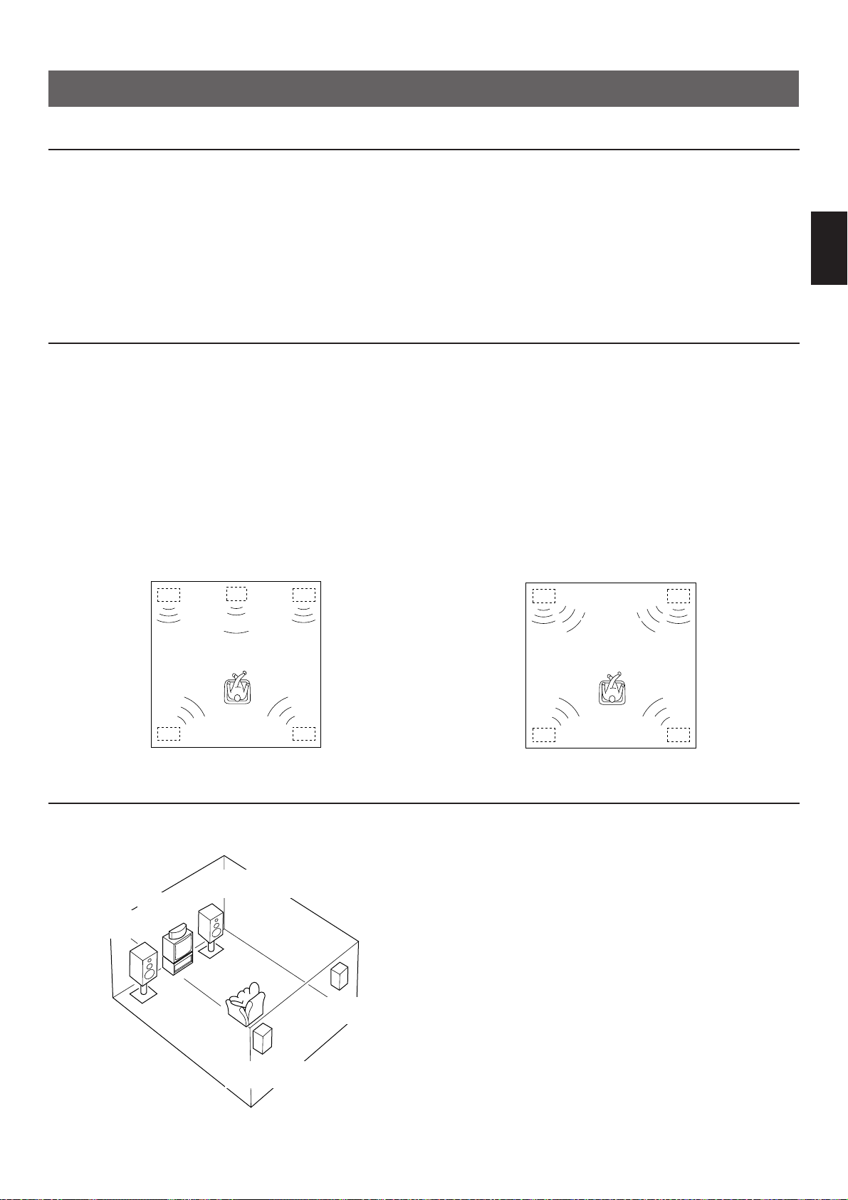
33
Français
INSTALLATION DES ENCEINTES ACOUSTIQUES
CHOIX DES ENCEINTES
C’est avec une composition à 5 enceintes que l’on obtiendra les meilleures performances sonores de cet appareil. Les enceintes
acoustiques que l’on doit utiliser sont les enceintes principales, les enceintes arrière et une enceinte centrale. Il est cependant
possible d’éliminer l’enceinte centrale. Se reporter à la rubrique “Composition à 4 enceintes” ci-dessous.
Les enceintes principales assurent l’émission du son de la source principale et des effets sonores. Ces enceintes sont probablement
celles de votre chaîne stéréo actuelle. Les enceintes arrière assurent l’émission des effets sonores et des sons ambiophoniques, et
l’enceinte centrale assure l’émission des sons centraux (dialogue, etc.) des programmes encodéess par le système ambiophonique
Dolby. Il n’est pas vraiment nécessaire que l’enceinte centrale soit aussi puissante que les enceintes principales, bien que les
enceintes arrière doivent être aussi puissantes. Veiller cependant à ce que toutes les enceintes soient d’une puissance au moins
égale à la puissance de sortie maximum de l’appareil.
EMPLACEMENT DES ENCEINTES
La composition recommandée à 5 enceintes requiert: une paire d’enceintes principales (les enceintes de votre chaîne stéréo
actuelle), une paire d’enceintes arrière et une enceinte centrale. Placer les enceintes comme indiqué ci-dessous.
Enceintes principales: Position normale. (Les positions
qu’elles occupent dans la chaîne
stéréo actuelle.)
Enceintes arrière: Derrière la position d’écoute, dirigées
légèrement vers l’intérieur. A environ
2 mètres au-dessus du sol.
Enceinte centrale: Exactement au milieu des enceintes
principales. (Pour éviter les
interférences avec le téléviseur,
utiliser une enceinte avec blindage
anti-magnétique.)
Dialog
Klangfeld
Dialog
Klangfeld
Enceinte
principale
gauche
Enceinte
arrière gauche
Enceinte
arrière droite
Enceinte
principale
droite
Enceinte centrale
Dialogue Dialogue
Enceinte
principale
gauche
Enceinte
arrière gauche
Enceinte
arrière droite
Enceinte
principale
droite
AmbiophonieAmbiophonie
Enceinte
principale gauche
Enceinte
arrière gauche
Enceinte
arrière droite
Enceinte
principale droite
Enceinte
centrale
Téléviseurs
COMPOSITION DES ENCEINTES
Composition à 5 enceintes
C’est une composition recommandée, et qui donnera les
meilleurs résultats. Dans cet agencement, l’enceinte centrale
joue un rôle tout aussi important que les enceintes arrière ou
avant. Lorsque le programme DOLBY PRO LOGIC ou DOLBY
PRO LOGIC ENHANCED est sélectionné, des conversations
seront émises à l’enceinte centrale, ce qui produira une
ambiophonie excellente.
●
Régler le sélecteur de mode de canal central sur la position
“NORMAL” ou “WIDE”. (Se reporter à la page 44 pour des
informations détaillées.)
Composition à 4 enceintes
Dans cet agencement, il n’y a pas d’enceinte centrale.
Lorsque le programme DOLBY PRO LOGIC ou DOLBY PRO
LOGIC ENHANCED est sélectionné, les sons normalement
acheminés à l’enceinte centrale seront émis aux enceintes
principales gauche et droite. Les effets sonores d’autres
programmes seront émis de la même manière que pour une
composition à 5 enceintes.
●
Veiller à régler le sélecteur de mode de canal central sur la
position “PHANTOM”. (Se reporter à la page 44 pour des
informations détaillées.)
Page 34

34
LES PARTIES DU PANNEAU ARRIERE ET LEURS
FONCTIONS
MONITOR
OUT
DVD/LD TV/DBS
IN OUT
VCR
VIDEO SIGNAL
CD
(LINE 1)
TAPE
( MD )
DVD/LD TV/DBS
VCR
TAPEPBREC
OUT
IN OUT
AUDIO SIGNAL
1
3 4
MAIN
TUNER
(LINE 2)
2
MAINS
SPEAKERS
OUTPUT
INPUT OUTPUT
l0 dB 0 dB
l
MAIN
LEVEL
SINGLE:8ΩMIN./SPEAKER
DUAL:4ΩMIN./SPEAKER
8ΩMIN./SPEAKER
CENTER
REAR
SINGLE:4ΩMIN./SPEAKER
DUAL:2ΩMIN./SPEAKER
6ΩMIN./SPEAKER
CENTER
REAR
IMPEDANCE SELECTOR
REAR CENTER
SUB
WOOFER
DUAL
(SURROUND)
DUAL
CAUTION
SEE INSTRUCTION MANUAL FOR CORRECT SETTING.
DUAL DUAL
SINGLE
REAR
CENTER
I00W MAX.
SWITCHED
AC OUTLET
6CH DISCRETE
INPUT
REARCENTERMAIN
SUB
WOOFER
(SURROUND) (SURROUND)
REARCENTERMAIN
SUB
WOOFER
INPUT
from
AMP/RECEIVER
PREOUT
1
890ABCD
23 4 567
1 Bornes d’entrée discrète à 6 canaux (6CH DISCRETE
INPUT)
Raccorder un décodeur numérique Dolby (AC-3) à ces bornes.
6 canaux (principal gauche, principal droit, central,
ambiophonique arrière gauche, ambiophonique arrière droit et
subwoofer) de signaux audio discrets avec le système
numérique Dolby (AC-3) décodé sont entrés à ces bornes à
partir du décodeur.
2 Bornes d’entrée (de la pré-sortie d’amplificateur/
récepteur) (INPUT (from AMP/RECEIVER PREOUT))
Ce sont des bornes supplémentaires d’entrée de signal audio à
6 canaux (pour les canaux principal gauche, principal droit,
central, ambiophonique arrière gauche, ambiophonique arrière
droit et subwoofer) disponibles pour entrer des signaux de
votre amplificateur, récepteur, processeur de son, etc., actuels
dans cet appareil.
Pour faire l’écoute des sons en reproduisant les signaux entrés
à ces bornes à partir de l’amplificateur externe, etc., veiller à
mettre le sélecteur PROCESSOR SELECTOR situé sur le
panneau avant à la position “EXTERNAL”. Ainsi, les signaux
entrés à ces bornes seront envoyés aux bornes SPEAKERS et
aux bornes OUTPUT correspondantes de cet appareil en
contournant tous les circuits de cet appareil. Il faut donc
contrôler le volume, la tonalité, etc., sur l’amplificateur externe.
3 Bornes de sortie principale (MAIN OUTPUT)
Sortie de ligne du canal principal. Raccordées aux bornes
d’entrée de l’amplificateur de puissance stéréo externe (bornes
MAIN IN ou bornes équivalentes de l’amplificateur ou du
récepteur intégré) entraînant les enceintes principales.
4 Sélecteur IMPEDANCE SELECTOR
Sélectionner la position correspondant à la configuration des
d’enceintes utilisées.
N’utiliser ce sélecteur que si cet appareil est hors-tension.
(Position droite)
Centrale: Si l’on utilise une seule enceinte centrale,
l’impédance de cette enceinte doit être de 8 Ω ou
plus.
Si l’on utilise une deux enceintes centrales,
l’impédance de chaque enceinte doit être de 4 Ω
ou plus.
Arrière: L’impédance de chaque enceinte doit être de 8 Ω
ou plus.
(Position gauche)
Centrale: Si l’on utilise une seule enceinte centrale,
l’impédance de cette enceinte doit être de 4 Ω ou
plus.
Si l’on utilise une deux enceintes centrales,
l’impédance de chaque enceinte doit être de 2 Ω
ou plus.
Arrière: L’impédance de chaque enceinte doit être de 6 Ω
ou plus.
ATTENTION
Ne changez pas le réglage du sélecteur d’impédance
IMPEDANCE SELECTOR lorsque l’amplificateur est sous
tension, car cela risquerait d’endommager l’appareil.
INTERNAL
EXTERNAL
PROCESSOR
SELECTOR
(Modèle pour l’Europe)
RACCORDEMENTS
Page 35

35
Français
5 Sélecteur MAIN LEVEL
<Modèles pour le Royaume-Uni et l’Europe seulement>
Ce sélecteur est normalement placé sur “0 dB”. Le cas
échéant, il est possible de diminuer le niveau de sortie aux
bornes MAIN OUTPUT de 10 dB en plaçant ce sélecteur sur
“–10 dB”.
6 PRISE CA (NON COMMUTEE)
Le cordon d’alimentation de n’importe quel appareil
audio/vidéo peut être raccordé à cette prise.
L’alimentation de cette prise n’est pas contrôlée par
l’interrupteur POWER de cet appareil. Cette prise fournira du
courant à l’appareil raccordé même si cet appareil est mis hors
tension.
La puissance maximale pouvant être tolérée à cette prise est
de 100 watts.
7 Cordon d’alimentation secteur
Après avoir accompli tous les branchements, raccorder ce
cordon à une prise secteur.
8 Bornes de raccord de signal audio (pour appareil
audio) (AUDIO SIGNAL)
Y raccorder les entrées et/ou sortie de l’appareil audio utilisé.
9 Bornes de raccord de signal audio/vidéo (pour
appareil vidéo) (AUDIO SIGNAL, VIDEO SIGNAL)
Y raccorder les entrées et/ou sorties de l’appareil vidéo utilisé
comme source.
0 Bornes d’enceintes d’effet arrière (REAR SPEAKERS)
Connecter les enceintes arrière à ces bornes en cas
d’utilisation de l’amplificateur de canal arrière incorporé.
A Bornes d’enceintes centrales (CENTER SPEAKERS)
Connecter une ou deux enceintes centrales à ces bornes en
cas d’utilisation de l’amplificateur incorporé de canal central.
B Bornes de sortie ambiophonique arrière (REAR
(SURROUND) OUTPUT)
Ces bornes sont la sortie de ligne du canal arrière. Lorsqu’on
utilise l’amplificateur intégré il n’y a pas de raccordement à ces
bornes.
Lorsque les enceintes arrière sont entraînées par un
amplificateur de puissance stéréo externe, raccorder les
bornes d’entrée de l’amplificateur (bornes MAIN IN ou AUX
d’un amplificateur de puissance ou d’un amplificateur intégré) à
ces bornes.
Remarque
Le niveau de sortie des signaux provenant des bornes MAIN,
REAR, CENTER et SUBWOOFER OUTPUT bornes est réglé
au moyen de la commande VOLUME du panneau avant ou
des touches VOLUME de la télécommande.
C Bornes de sortie centrale (CENTER OUTPUT)
Ces bornes sont la sortie de ligne du canal central. Lorsqu’on
utilise l’amplificateur intégré, il n’y a pas de raccordement à ces
bornes.
Lorsque l’enceinte centrale est entraînée par un amplificateur
de puissance stéréo externe, raccorder la borne d’entrée de
l’amplificateur externe entraînant une enceinte centrale à l’une
de ces bornes.
Si l’on entraîne deux enceintes centrales avec des
amplificateurs externes, raccorder la borne d’entrée de
l’amplificateur externe entraînant une autre enceinte centrale à
l’autre borne.
D Bornes de sortie subwoofer (SUBWOOFER OUTPUT)
Il est possible d’ajouter un subwoofer afin d’accentuer les
basses fréquences.
Ces bornes sont des sorties de niveau de ligne utilisées pour
raccorder l’amplificateur (les amplificateurs) entraînant le(s)
subwoofer(s).
Lorsque les signaux d’entrée pour cet appareil sont de type
stéréo normal à 2 canaux, ces bornes émettent seulement des
fréquences inférieures à 150 Hz (200 Hz pour le modèle
général seulement) sur les canaux principal et central. Lorsque
des signaux décodés avec le système numérique Dolby (AC-3)
sont entrés dans cet appareil et sont sélectionnés comme
source d’entrée, ces bornes émettent des signaux par le canal
de woofer auxiliaire.
Page 36

36
MONITOR
OUT
DVD/LD TV/DBS
IN OUT
VCR
VIDEO SIGNAL
CD
(LINE 1)
TAPE
( MD )
DVD/LD TV/DBS
VCR
TAPEPBREC
OUT
IN OUT
AUDIO SIGNAL
1 3 4
MAIN
TUNER
(LINE 2)
2
(SURROUND)
REAR
CENTERMAIN
SUB
WOOFER
INPUT
from
AMP/RECEIVER
PREOUT
OUTPUT OUTPUT
l0 dB 0 dB
l
MAIN
LEVEL
6CH DISCRETE
INPUT
REAR
CENTERMAIN
SUB
WOOFER
(SURROUND)
I00W MAX.
SWITCHED
AC OUTLET
MAINS
INPUT
OUTPUT
OUTPUT
LINE OUT
LINE IN
VIDEO OUT
AUDIO OUT
AUDIO OUT
AUDIO IN
VIDEO IN
VIDEO OUT
AUDIO OUT
VIDEO OUT
MAIN IN
VIDEO IN
EXEMPLES DE BRANCHEMENTS DE BASE
Ne jamais brancher cet appareil et les autres composants avant d’avoir accompli tous les
raccordements.
Remarque
Lors du raccordement de cet appareil aux autres composants veiller à ce que tous les branchements soient effectués correctement,
c’est-à-dire entre “L” (gauche) et “L”, entre “R” (droite) et “R”, entre “+” et “+” et entre “–” et “–”.
Voir aussi le mode d’emploi de chaque appareil branché à cet appareil.
* S’il y a des composants YAMAHA numérotés
1, 2, 3, etc. sur le panneau arrière, il est possible d’effectuer facilement les
raccordements en raccordant les bornes de sortie (ou d’entrée) de chaque composant aux bornes portant les mêmes numéros sur
cet appareil.
1
Lorsque cet appareil est utilisé comme contrôleur principal
(Modèle pour l’Europe)
Vers une
prise CA
Moniteur TV
Amplificateur (entraîner les
enceintes principales)
Magnétoscope
Syntonisateur
TV/Satellite
Platine à cassette,
magnetophone à
minidisque, etc.
Lecteur de disque
compact
Lecteur de disque
laser, etc.
Enceintes principale
Gauche
Droite
Syntonisateur
Remarques
●
Avec cette méthode de branchement, le sélecteur
PROCESSOR SELECTOR situé sur le panneau avant de
cet appareil doit être mis à la position “INTERNAL”.
●
Pour ce qui concerne les branchements des enceintes, se
reporter aux pages 38 et 39.
Se reporter à
la page 37.
Page 37

37
Français
Raccordement à un décodeur numérique Dolby (AC-3)
Si l’on a un décodeur numérique Dolby (AC-3) ou un lecteur de disque laser, etc., incorporant un décodeur numérique Dolby (AC-
3), ses sorties discrètes peuvent être raccordées à cet appareil.
Remarques
• Le lecteur de disque laser (ou un autre appareil) doit aussi
être raccordé aux bornes DVD/LD (ou TV/DBS) AUDIO
SIGNAL INPUT de cet appareil pour reproduire une source
en décodant l’effet Logique Pro d’effet ambiophonique Dolby
ou en mode stéréo (ou mono) normal.
• Les signaux discrets parvenant à cet appareil ne peuvent
pas être enregistrés par une platine à cassette, un
magnétophone à minidisque ou un magnétoscope. Pour
enregistrer une source reproduite sur le lecteur de disque
laser (ou un autre appareil), il faut raccorder cette source aux
bornes DVD/LD (ou TV/DBS) AUDIO/VIDEO SIGNAL INPUT
de cet appareil.
• Si l’on n’a fait aucun raccordement à la borne d’entrée
SUBWOOFER de cet appareil ou si l’on n’utilise pas de hautparleurs pour ultra-graves, il faut effectuer un réglage pour
distribuer les signaux au canal LFE aux bornes de sortie
MAIN droite et gauche du décodeur numérique Dolby
(AC-3).
Pour plus de détails, se reporter au mode d’emploi du
décodeur numérique Dolby (AC-3).
MONITOR
OUT
DVD/LD TV/DBS
IN OUT
VCR
VIDEO SIGNAL
CD
(LINE 1)
TAPE
( MD )
DVD/LD TV/DBS
VCR
TAPEPBREC
OUT
IN OUT
AUDIO SIGNAL
1 3 4
TUNER
(LINE 2)
2
(SURROUND)
REAR
CENTERMAIN
SUB
WOOFER
INPUT
from
AMP/RECEIVER
PREOUT
INPUT
6CH DISCRETE
INPUT
REAR
CENTERMAIN
SUB
WOOFER
(SURROUND)
AC-3 RF
OUT
AC-3 RF
IN
DIGITAL
IN
DIGITAL
OUT
VIDEO OUT
AUDIO OUT
6CH DISCRETE OUTPUT
CENTER SURROUND
SUB
WOOFER
MAIN
Décodeur numérique Dolby (AC-3)
Démodulateur RF
Lecteur de disque laser avec sortie AC-3 RF
ou un autre appareil avec sortie AC-3 RF
Page 38

38
Rouge: positif (+)
Noir: négatif (–)
1 Dévisser le bouton.
2 Introduire le câble
dénudé.
(Enlever environ 5 mm
de gaîne pour dénuder
le câble.)
3 Revisser le bouton et
fixer le câble.
<Modèlo général seulement>
Il est également possible d’utiliser des fiches banane.
Il suffit d’introduire la fiche banane dans la borne
correspondante.
1
2
3
Branchement aux bornes REAR et CENTER SPEAKERS:
Raccorder les bornes SPEAKERS aux enceintes avec des câbles de section adéquate et aussi courts que possible. Si les
branchements sont mal faits, aucun son ne sera entendu aux enceintes. Respecter la polarité des câbles de raccord (repères + et
–). Si les polarités sont inversées, le son perçu manquera de naturel et de profondeur de basses.
Précaution
Veiller à ce que les portions dénudées des câbles ne se touchent pas et n’entrent pas en contact avec des pièces
métalliques de cet apparei. Ceci pourrait endommager l’appareil et/ou les enceintes.
Remarque
Utiliser des enceintes dont l’impédance correspond à la valeur indiquée à l’arrière de l’appareil.
RACCORDEMENT DES ENCEINTES
MAIN
SPEAKERSOUTPUT OUTPUT
l0 dB 0 dB
l
MAIN
LEVEL
SINGLE:8ΩMIN./SPEAKER
DUAL
:4ΩMIN./SPEAKER
8ΩMIN./SPEAKER
CENTER
REAR
SINGLE:4ΩMIN./SPEAKER
DUAL
:2ΩMIN./SPEAKER
6ΩMIN./SPEAKER
CENTER
REAR
IMPEDANCE SELECTOR
REAR CENTER
SUB
WOOFER
DUAL
(SURROUND)
DUAL
CAUTION
SEE INSTRUCTION MANUAL FOR CORRECT SETTING.
DUAL DUAL
SINGLE
REAR
CENTER
Amplificateur
(entraîner les enceintes
principales)
Enceinte centraleEnceintes arrière
Enceintes
principale
Subwoofer de Traitement
(Modèle pour l’Europe)
Gauche Droite
GaucheDroite
Page 39

39
Français
Branchements des enceintes
principales
Cet appareil n’est pas équipé d’amplificateurs pour entraîner
les enceintes principales; il faut donc raccorder un
amplificateur externe (amplificateur de puissance, amplificateur
intégré, récepteur, etc.) pour entraîner les enceintes
principales à cet appareil.
Raccorder les bornes de sortie principale MAIN OUTPUT de
cet appareil aux bornes d’entrée principale MAIN IN (ou bornes
équivalentes) de l’amplificateur externe, et raccorder les
enceintes principales aux bornes d’enceintes de l’amplificateur
externe.
Remarques
●
Si l’amplificateur externe n’est pas équipé de bornes MAIN
IN (ou bornes équivalentes), il est possible de raccorder cet
appareil aux bornes d’entrée AUX (ou TAPE PB) de
l’amplificateur. Dans ce cas, veiller à sélectionner la position
de source d’entrée “AUX” (ou “TAPE”) et ne pas choisir une
autre sélection de source d’entrée.
●
Pour obtenir le rendement optimal de cet appareil, régler la
commande de volume de l’amplificateur externe à la
position située approximativement à mi-chemin entre les
positions minimum et maximum.
Branchements des enceintes
centrales
Il est possible de raccorder une ou deux enceintes centrales à
cet appareil. S’il n’est pas possible de placer l’enceinte centrale
sur ou sous le téléviseur, il est recommandé d’utiliser deux
enceintes centrales et de les placer sur les deux côtés du
téléviseur afin d’orienter le son vers la position centrale. Pour
raccorder deux enceintes centrales, suivre la méthode
indiquées sur l’illustration ci-dessous.
Branchement d’un subwoofer
Il est possible d’ajouter un subwoofer afin d’accentuer les
basses fréquences.
Connecter l’une ou l’autre des bornes SUBWOOFER OUTPUT
à la borne INPUT de l’amplificateur de subwoofer et connecter
les bornes d’enceinte de l’amplificateur de subwoofer au
subwoofer.
Pour obtenir plus de présence sonore dans la salle d’écoute, il
est recommandé d’utiliser deux subwoofers. Pour raccorder
deux subwoofers à cet appareil, raccorder une borne
SUBWOOFER OUTPUT à la borne INPUT de l’amplificateur
pilotant un subwoofer, et l’autre borne SUBWOOFER OUTPUT
à la borne INPUT de l’amplificateur pilotant l’autre subwoofer,
puis raccorder chaque subwoofer à l’amplificateur
correspondant.
Avec certains subwoofers, dont le Subwoofer de Traitement
par Asservissement Actif de Yamaha, l’amplificateur et le
subwoofer sont combinés.
DUAL DUAL
SINGLE
REAR
CENTER
SPEAKERS
CAUTION
SEE INSTRUCTION MANUAL FOR CORRECT SETTING.
OUTPUT
REAR CENTER
SUB
WOOFER
DUAL
(SURROUND)
DUAL
Subwoofer
de Traitement
Subwoofer de
Traitement
Enceinte centrale Enceinte centrale
Page 40

40
2
Branchement à votre amplificateur intégré ou votre récepteur actuels
ne pouvant pas recevoir de signaux avec le système numérique Dolby
(AC-3) décodé
(Ce schéma représente cet appareil raccordé au Yamaha DSP-A2070 qui est équipé du processeur de champ sonore
numérique, du décodeur d’effet ambiophonique Dolby Pro Logic et des amplificateurs entraînant sept enceintes.)
MONITOR
OUT
DVD/LD TV/DBS
IN OUT
VCR
VIDEO SIGNAL
CD
(LINE 1)
TAPE
( MD )
DVD/LD TV/DBS
VCR
TAPEPBREC
OUT
IN OUT
AUDIO SIGNAL
1
3 4
MAIN
TUNER
(LINE 2)
2
(SURROUND)
REARCENTERMAIN
SUB
WOOFER
INPUT
from
AMP/RECEIVER
PREOUT
MAINS
SPEAKERS
OUTPUT
INPUT OUTPUT
l0 dB 0 dB
l
MAIN
LEVEL
SINGLE:8ΩMIN./SPEAKER
DUAL:4ΩMIN./SPEAKER
8ΩMIN./SPEAKER
CENTER
REAR
SINGLE:4ΩMIN./SPEAKER
DUAL:2ΩMIN./SPEAKER
6ΩMIN./SPEAKER
CENTER
REAR
IMPEDANCE SELECTOR
REAR CENTER
SUB
WOOFER
DUAL
(SURROUND)
DUAL
CAUTION
SEE INSTRUCTION MANUAL FOR CORRECT SETTING.
DUAL DUAL
SINGLE
REAR
CENTER
I00W MAX.
SWITCHED
AC OUTLET
6CH DISCRETE
INPUT
REARCENTERMAIN
SUB
WOOFER
(SURROUND)
CENTER IN
MAIN IN
REAR OUT
CENTER OUT
LOW PASS
MAIN OUT
AUDIO OUT
VIDEO OUT
AC-3 RF OUT
AC-3 RF IN
Enceinte principale
Front effect speaker
Enceinte centrale
Enceintes arrière
Subwoofer de
Traitement
Front effect speaker
Enceinte principale
Décodeur numérique
Dolby (AC-3)
Démodulateur RF
(Modèle APD-1 de
YAMAHA, etc.)
Lecteur de disque laser, etc.
Amplificateur
ou récepteur
Vers une
prise CA
Equipement audio/vidéo
(Modèle pour l’Europe)
Gauche
Gauche
Droite
Droite
GaucheDroite
Remarques
●
Pour ce qui concerne le branchement aux bornes 6CH
DISCRETE INPUT de cet appareil, se reporter à la page 37.
●
Pour ce qui concerne le branchement des enceintes arrière
et du (des) subwoofer(s) à cet appareil, se reporter aux
pages 38 et 39.
●
Avec cette méthode de branchement, le sélecteur
PROCESSOR SELECTOR situé sur le panneau avant doit
normalement être mis sur la position “EXTERNAL”. Lorsqu’on
veut effectuer la lecture d’une source sur un lecteur de disque
laser, etc., (raccordé à cet appareil) avec le système
numérique Dolby (AC-3) décodé, mettre le sélecteur
PROCESSOR SELECTOR sur la position “INTERNAL”.
Page 41

41
Français
1 Interrupteur d’alimentation (POWER)
Le presser pour fournir l’alimentation. Le presser à nouveau
pour couper l’alimentation.
2 Capteur de télécommande
Il reçoit les signaux transmis par la télécommande.
3 Panneau d’affichage
Indique diverses informations. (Pour plus de détails, voir les
page 43.)
4 Sélecteurs d’entrée
Ils permettent de sélectionner la source de programme que l’on
veut écouter ou visionner. Lorsqu’on appuie sur un sélecteur,
le nom de la source sélectionnée apparaît sur l’affichage.
5 Sélecteur 2CH/6CH
Lorsque la source d’entrée TV/DBS ou DVD/LD est
sélectionnée, les signaux d’entrée passeront des signaux
stéréo à 2 canaux aux signaux discrets à 6 canaux et viceversa lorsqu’on appuie sur ce sélecteur. Lorsque le sélecteur
est mis sur la position “6CH”, les signaux provenant d’un
décodeur numérique Dolby (AC-3), etc., branché aux bornes
6CH DISCRETE INPUT de cet appareil seront sélectionnés
comme signaux d’entrée.
6 Commande du niveau de volume sonore (VOLUME)
Elle permet d’augmenter ou de diminuer le niveau du volume.
7 Touche d’effet (EFFECT)
Met en/hors circuit le processeur de champ sonore numérique
(y compris le décodeur d’effet ambiophonique Dolby Pro Logic)
8 Sélecteurs de programme DSP
Ils permettent de sélectionner un programme DSP. Lorsqu’on
appuie sur un sélecteur, le nom du programme sélectionné
s’allume sur l’affichage.
9 Touche de mode de canal central (CENTER MODE)
Permet de sélectionner un mode de sortie de canal central.
(NORMAL, WIDE ou PHANTOM).
(Pour plus de détails, voir la page 44.)
0 Touches de retard/centre/arrière/woofer auxiliaire
(DELAY/CENTER/REAR/SWFR) et
d’augmentation/diminution d’heure/niveau
(TIME/LEVEL +/–)
Ces touches permettent de régler le temps de retard (DELAY),
le niveau de sortie de canal central (CENTER), le niveau de
sortie de canal arrière (REAR) et le niveau de sortie à la borne
de sortie de woofer auxiliaire (SUBWOOFER OUTPUT)
(SWFR). Sélectionner l’élément que l’on veut régler en
appuyant sur la touche DELAY/CENTER/REAR/SWFR et
régler l’heure ou le niveau pour cet élément en appuyant sur la
touche TIME/LEVEL +/–.
A Sélecteur de processeur (PROCESSOR SELECTOR)
Lorsqu’on effectue la lecture d’une source sur un appareil
audio/vidéo raccordé à cet appareil, mettre ce sélecteur sur la
position “INTERNAL”. Lorsqu’on effectue l’écoute de sons
reproduisant des signaux entrés aux bornes INPUT (from
AMP/RECEIVER PREOUT) situées sur le panneau arrière à
partir de l’amplificateur externe, etc., mettre ce sélecteur sur la
position “EXTERNAL”.
LES COMMANDES ET LEURS FONCTIONS
PANNEAU AVANT
NATURAL SOUND AV PROCESSOR/AMPLIFIER
DSP–E492
CINEMA DSP
POWER
VOLUME
l6
20
28
40
60
l2
8
4
2
0
–dB
DELAY/CENTER
/REAR/SWFR
CENTER
MODE
TIME/LEVEL
INTERNAL
EXTERNAL
PRESET
kHz
MHz
MEMORY AUTO PTY HOLD
SLEEP
TAPE MONITOR
STEREO
ms dB
PRO LOGIC
ENHANCED
CONCERT
VIDEO
MONO
MOVIE
STADIUM
DISCO
ROCK CONCERT
CONCERT HALL
VCR DVD/LD
2CH
/
6CH
TV/DBS
TAPE (MD)
MONITOR
TUNER
(LINE 2)
CD
(LINE 1)
NORMAL
WIDE
PHANTOM
EFFECT OFF
PS
EON
INFO AFFAIRS SPORT
NEWS
RT CTPTY
0
20
l00
40 60
EFFECT
PRO LOGIC
ENHANCED MONO MOVIE STADIUM
PROCESSOR
SELECTOR
DISCO
ROCK CONCERT CONCERT HALLCONCERT VIDEO
1
78 9 A
2456
0
3
Page 42
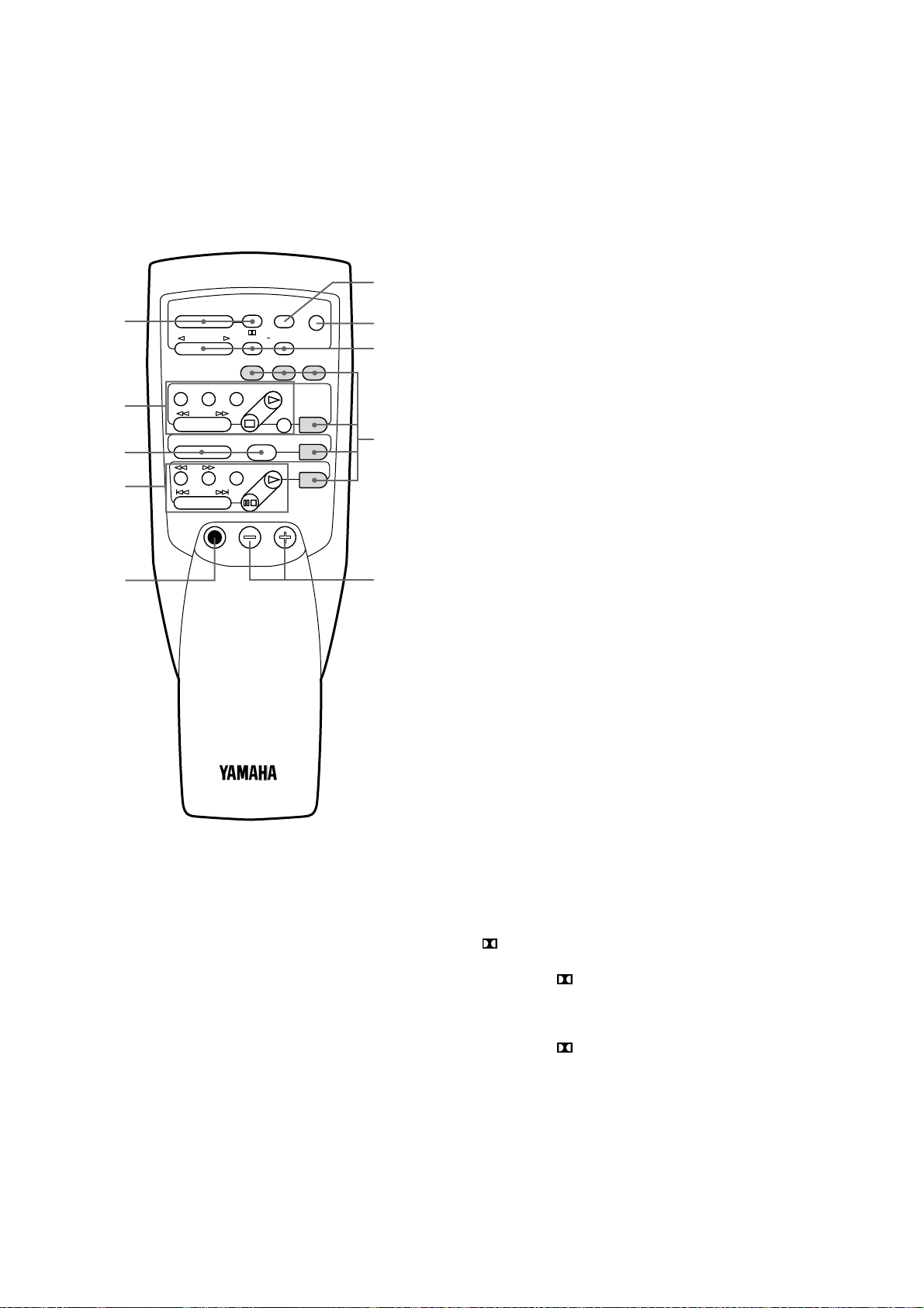
42
Pour commander cet appareil
1 Touches de retard/centre/arrière/woofer auxiliaire
(DELAY/CENTER/REAR/SWFR) et d’augmentation/
diminution d’heure/niveau (TIME/LEVEL +/–)
Ces touches permettent de régler le temps de retard (DELAY),
le niveau de sortie de canal central (CENTER), le niveau de
sortie de canal arrière (REAR) et le niveau de sortie à la borne
de sortie de woofer auxiliaire (SUBWOOFER OUTPUT)
(SWFR).
Sélectionner l’élément que l’on veut régler en appuyant sur la
touche DELAY/CENTER/REAR/SWFR et régler l’heure ou le
niveau pour cet élément en appuyant sur la touche
TIME/LEVEL +/–.
2 Sélecteur 2CH/6CH
Lorsque la source d’entrée TV/DBS ou DVD/LD est
sélectionnée, les signaux d’entrée passeront des signaux
stéréo à 2 canaux aux signaux discrets à 6 canaux et viceversa lorsqu’on appuie sur ce sélecteur. Lorsque le sélecteur
est mis sur la position “6CH”, les signaux provenant de d’un
décodeur numérique Dolby (AC-3), etc., branché aux bornes
6CH DISCRETE INPUT de cet appareil seront sélectionnés
comme signaux d’entrée.
3 Touches d’augmentation/diminution de volume sonore
(VOLUME +/–)
Ces touches permettent d’augmenter et de diminuer le volume.
4 Sélecteurs d’entrée
Ils permettent de sélectionner la source d’entrée.
5 Touches de sélection de programmes
PROGRAM:
Lorsque le processeur de champ sonore numérique incorporé
(y compris le décodeur déffet ambiophonique Dolby Pro Logic)
est en circuit, cette touche permet de changer le programme
DSP actuellement sélectionné en appuyant sur le côté droit ou
gauche de cette touche.
PROLOGIC:
Cette touche permet de sélectionner directement le
programme PRO LOGIC.
ENHANCED:
Cette touche permet de sélectionner directement le
programme PRO LOGIC ENHANCED.
6 Commutateur d’effet (EFFECT ON/OFF)
Met en/hors circuit le processeur de champ sonore numérique
(y compris le décodeur d’effet ambiophonique Dolby Pro Logic)
7 Touche de test (TEST)
Sert à régler l’équilibre sonore des enceintes. (Pour plus de
détails, voir les pages 44 et 45.)
TELECOMMANDE
La télécommande fournie avec cet appareil permet de commander toutes les fonctions les plus utilisées de cet appareil. Si le lecteur
de disque compact, le syntonisateur et la platine à cassette raccordés à cet appareil sont des appareils YAMAHA compatibles avec
le fonctionnement télécommande, alors il sera aussi possible de commander les diverses fonctions de chacun des appareils avec
cette télécommande.
REC/PAUSE
DIR BDIR A
PLAY
DISC
2CH/6CH VOLUME
PLAY
PRESET
A/B/C/D/E
–+
TIME/
LEVEL
TEST
EFFECT
PROGRAM
PROLOGIC
ENHANCED
–+
TAPE
A/B
ON/OFF
TUNER L2
CD L1
DELAY/CENTER
/REAR/SWFR
DVD/LD
VCR
TV/DBS
2
2
3
6
7
4
5
3
1
1
Page 43

43
Français
TAPE MON
ms dB
PRO LOGIC
ENHANCED
CONCERT
VIDEO
MONO
MOVIE
STADIUM
DISCO
ROCK CONCERT
CONCERT HALL
NORM
WIDE
PHANTOM
EFFECT OFF
1
23
4
5
1 Affichage multi-informations
Il affiche diverses informations, par exemple le nom du
programme DSP sélectionné et le nom de la source d’entrée
sélectionnée.
2 Indicateurs de mode de canal central
Le nom d’un mode de canal central sélectionné s’allume
seulement lorsqu’un programme qui utilise le décodeur d’effet
ambiophonique Dolby Pro Logic est sélectionné.
3 Indicateur EFFECT OFF
Il s’allume si ni le processeur de champ sonore numérique ni le
décodeur d’effet ambiophonique Dolby Pro Logic ne sont en
circuit. Dans cet état, le son émis est du type stéréo à 2
canaux.
4 Indicateur de contrôle de bande (TAPE MON)
Il s’allume lorsqu’on a sélectionné la platine à cassette (ou le
magnétophone à minidisque, etc.) comme source d’entrée en
appuyant sur la touche TAPE (MD) MONITOR.
5 Indicateurs de programme de processeur de champ
sonore (DSP)
Le nom d’un programme DSP sélectionné s’allume lorsque le
processeur de champ sonore numérique incorporé et/ou le
décodeur d’effet ambiophonique Dolby Pro Logic est en circuit.
PANNEAU D’AFFICHAGE
Pour la commande des autres appareils
Identifier les touches de la télécommande à l’aide des touches
de l’appareil. Si ces touches sont identiques, leurs fonctions
seront aussi identiques. Pour ce qui concerne les fonctions
des touches, se reporter à l’instruction correspondante du
manuel de l’appareil.
1 Touches de platine à cassette
Elles permettent de commander une platine à cassette.
* Les touches DIR A, B et A/B sont utilisables seulement avec
une platine à deux cassettes.
* Pour les platines à une seule cassette équipées de la
fonction de rebobinage automatique, le sens de défilement
de la bande sera inversé lorsqu’on appuie sur la touche
DIR A.
2 Touches de syntonisateur
Ces touches permettent de commander le syntonisateur.
+: Sélectionne le numéro de station préréglée supérieur.
–: Sélectionne le numéro de station préréglée inférieur.
A/B/C/D/E:
Permettent de sélectionner les numéros de stations
préréglées des groupes correspondants (A à E).
3 Touche de lecteur de disque compact
Elles permettent de commander un lecteur de disque compact.
* La touche DISC est utilisable seulement avec un changeur
de disques compacts.
Page 44

1
Régler à la position “∞”.
2 Mettre cet appareil et l’amplificateur externe, etc., sous
tension.
3 Mettre la commande de balance, les commandes de
tonalité, etc. de l’amplificateur externe sur la position
“plate”.
4
5 Sélectionner le mode de sortie de canal central
convenant à la composition d’enceintes utilisée.
(Se reporter à la section “COMPOSITION DES
ENCEINTES”, page 33.)
Pour les caractéristiques propres à chaque mode, se reporter
à la section “Remarque” ci-dessous.
Remarque
Lors de la sélection d’un mode de sortie de canal central à
l’étape 5, noter les points suivants.
Pour une composition à 5 enceintes
NORMAL: Choisir ce mode lorsque l’enceinte centrale utilisée
est plus petite que l’enceinte principale. Dans ce
mode, les basses sont émises aux enceintes
principales.
WIDE: Choisir ce mode lorsque l’enceinte centrale utilisée
est à peu près de la même taille que l’enceinte
principale.
Pour une composition à 4 enceintes
PHANTOM: Choisir ce mode lorsqu’on n’utilise pas d’enceinte
centrale. Les sons normalement émis à l’enceinte
centrale seront alors émis aux enceintes
principales gauche et droite.
44
CENTER
MODE
NORMAL
WIDE
PHANTOM
En utilisant le générateur de tonalité de test incorporé, cette procédure permet de régler l’équilibre du niveau de sortie des sons entre
les enceintes principales, arrière et centrale. Lorsqu’on effectue ce réglage, le niveau sonore sera identique à la position d’écoute pour
chacune des enceintes. Ce réglage est particulièrement important pour assurer la meilleure performance du processeur de champ
sonore numérique et du décodeur d’effet ambiophonique Dolby Pro Logic.
Le réglage du niveau de sortie de chaque enceinte doit être effectué à la position d’écoute à l’aide de la télécommande.
Sinon, le résultat obtenu ne sera pas satisfaisant.
Remarque
Si cet appareil est raccordé à un décodeur numérique Dolby (AC-3) et/ou à un amplificateur (ou un récepteur) équipé du décodeur
Dolby Pro Logic ou du processeur de champ sonore numérique, effectuer aussi un réglage de la balance de sortie à l’aide de la
tonalité d’essai sur chaque appareil.
l6
20
28
40
60
l2
8
4
2
0
–dB
VOLUME
POWER
REC/PAUSE
DIR BDIR A
PLAY
DISC
2CH/6CH VOLUME
PLAY
PRESET
A/B/C/D/E
–+
TIME/
LEVEL
TEST
EFFECT
PROGRAM
PROLOGIC
ENHANCED
–+
TAPE
A/B
ON/OFF
TUNER L2
CD L1
DELAY/CENTER
/REAR/SWFR
DVD/LD
VCR
TV/DBS
1
2
NATURAL SOUND AV PROCESSOR/AMPLIFIER
DSP–E492
CINEMA DSP
POWER
VOLUME
l6
20
28
40
60
l2
8
4
2
0
–dB
DELAY/
CENTER/REAR
CENTER
MODE
TIME/LEVEL
INTERNAL
EXTERNAL
PRESET
kHz
MHz
MEMORY AUTO PTY HOLD
SLEEP
TAPE MONITOR
STEREO
ms dB
PRO LOGIC
ENHANCED
CONCERT
VIDEO
MONO
MOVIE
STADIUM
DISCO
ROCK CONCERT
CONCERT HALL
VCR DVD/LD
2CH
/
6CH
TV/DBS
TAPE (MD)
MONITOR
TUNER
(LINE 2)CD(LINE 1)
NORMAL
WIDE
PHANTOM
EFFECT OFF
PS
EON
INFO AFFAIRS SPORT
NEWS
RT CTPTY
0
20
l00
40 60
EFFECT
PRO LOGIC
ENHANCED MONO MOVIE STADIUM
PROCESSOR
SELECTOR
DISCO
ROCK CONCERT CONCERT HALLCONCERT VIDEO
4, 8
TEST
5
6
7
REGLAGE DE LA BALANCE DES ENCEINTES
Page 45

45
Français
6 Augmenter le volume.
L’appareil émet alors un son d’essai (bruit rose)
successivement à l’enceinte principale gauche, à l’enceinte
centrale, à l’enceinte principale droite et aux enceintes
arrière, pendant deux secondes pour chaque enceinte.
L’affichage change alors comme indiqué ci-dessous.
* Les sons-test des enceintes arrière gauche et droite
seront entendus simultanément.
7 Régler les niveaux de sortie des sons à l’enceinte
centrale et aux enceintes arrière de manière qu’ils
soient pratiquement identiques à celui des enceintes
principales.
a) Appuyer une fois ou plus de manière que l’indication
“CENTER” ou “REAR” apparaisse sur l’affichage.
* Sélectionner “CENTER” pour régler le niveau de
sortie de l’enceinte centrale, et sélectionner “REAR”
pour régler le niveau de sortie des enceintes arrière.
b) Régler son niveau.
* Le niveau du son augmente lorsqu’on appuie sur le
côté + de la touche, et il diminue lorsqu’on appuie sur
le côté –.
8 Annuler le son d’essai.
Remarques
●
Après avoir effectué ces réglages, il est possible de régler
le niveau sonore global de la chaîne au moyen de la
commande VOLUME de cet appareil (ou des touches
VOLUME de la télécommande seulement).
●
On pourra aussi utiliser les commandes de volume de
l’amplificateur externe, etc. pour obtenir un bon équilibre
sonore.
●
A l’étape 7, si le mode de canal central est sur la position
“PHANTOM”, on ne pourra pas régler le niveau de sortie
sonore de l’enceinte centrale. En effet, à ce mode, les
sons normalement émis à l’enceinte centrale sont
automatiquement acheminés aux enceintes principales
gauche et droite.
<Modèles pour le Royaume-Uni et l’Europe seulement>
●
Si l’émission sonore des enceintes centrales et arrière est
insuffisante, on peut diminuer le niveau de sortie des
enceintes principales en réglant le commutateur MAIN
LEVEL du panneau arrière de l’appareil sur “–10 dB”.
Principale (gauche)
Principale (droite)
Centrale
Arrière (gauche et droite)
TIME/
LEVEL
–+
DELAY/CENTER
/REAR/SWFR
Disparait
TEST
VOLUME
Page 46
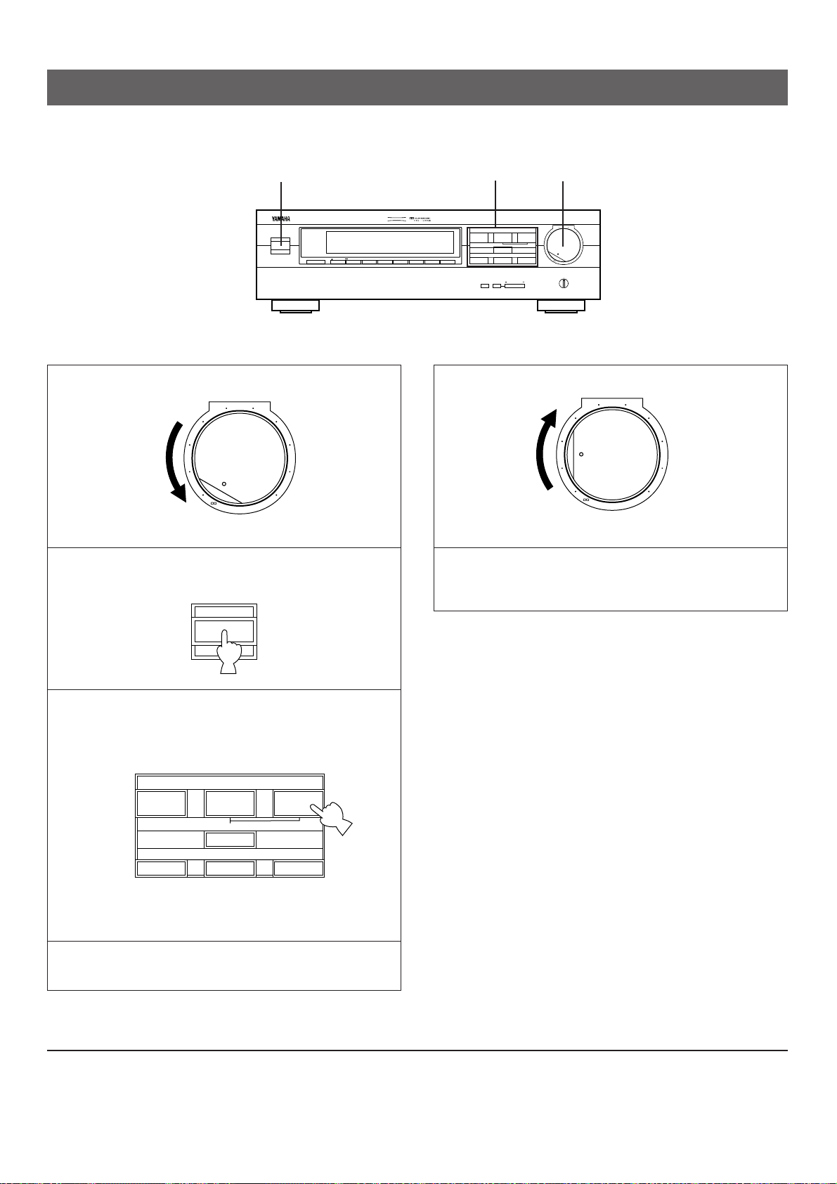
46
1
Régler à la position “∞”.
2 Mettre cet appareil et les autres appareils audio/vidéo
que l’onveut utiliser sous tension.
3 Sélectionner la source d’entrée désirée au moyen des
sélecteurs d’entrée.
(Pour ce qui concerne les sources vidéo, mettre sous
tension le téléviseur ou le moniteur.)
* Le nom de la source d’entrée sélectionnée apparaît à
l’affichage.
4 Mettre en marche la source.
5
Régler le volume au niveau désiré.
6 Le cas échéant, utiliser le processeur de champ sonore
numérique. (Se reporter à la page 50.)
Remarque
Vérifier que le sélecteur PROCESSOR SELECTOR soit bien
mis sur la position “INTERNAL”. S’il est mis sur la position
“EXTERNAL”, le faire passer sur la position “INTERNAL”.
Remarque concernant l’utilisation des sélecteurs d’entrée
●
Bien noter que le fait d’appuyer sur chacun des sélecteurs
d’entrée a pour résultat de sélectionner la source qui est
raccordée aux bornes d’entrée correspondantes situées sur
le panneau arrière.
●
La sélection de TAPE (MD) MONITOR ne peut pas être
annulée en appuyant sur un autre sélecteur d’entrée. Pour
l’annuler, appuyer à nouveau sur la touche TAPE (MD)
MONITOR de manière que “TAPE MON” disparaisse de
l’affichage.
Lorsqu’on sélectionne une touche autre que TAPE (MD)
MONITOR, s’assurer que “TAPE MON” n’est pas allumé sur
l’affichage.
●
Si l’on sélectionne le sélecteur d’entrée d’une source vidéo
sans annuler la sélection de TAPE (MD) MONITOR, on
obtiendra l’image vidéo de la source vidéo et le son de la
cassette audio (ou d’un minidisque, etc.).
●
Lorsqu’on effectue la lecture d’une source vidéo, son image
vidéo ne sera pas interrompue même si le sélecteur
d’entrée pour une source audio est sélectionné.
REPRODUCTION D’UNE SOURCE
l6
20
28
40
60
l2
8
4
2
0
–dB
VOLUME
l6
20
28
40
60
l2
8
4
2
0
–dB
VOLUME
VCR DVD/LD
2CH
/
6CH
TV/DBS
TAPE (MD)
MONITOR
TUNER
(LINE 2)
CD
(LINE 1)
POWER
1, 5
2
NATURAL SOUND AV PROCESSOR/AMPLIFIER
DSP–E492
CINEMA DSP
POWER
VOLUME
l6
20
28
40
60
l2
8
4
2
0
–dB
DELAY/
CENTER/REAR
CENTER
MODE
TIME/LEVEL
INTERNAL
EXTERNAL
PRESET
kHz
MHz
MEMORY AUTO PTY HOLD
SLEEP
TAPE MONITOR
STEREO
ms dB
PRO LOGIC
ENHANCED
CONCERT
VIDEO
MONO
MOVIE
STADIUM
DISCO
ROCK CONCERT
CONCERT HALL
VCR DVD/LD
2CH
/
6CH
TV/DBS
TAPE (MD)
MONITOR
TUNER
(LINE 2)CD(LINE 1)
NORMAL
WIDE
PHANTOM
EFFECT OFF
PS
EON
INFO AFFAIRS SPORT
NEWS
RT CTPTY
0
20
l00
40 60
EFFECT
PRO LOGIC
ENHANCED MONO MOVIE STADIUM
PROCESSOR
SELECTOR
DISCO
ROCK CONCERT CONCERT HALLCONCERT VIDEO
3
Pour mettre l’appareil hors tension
Appuyer à nouveau sur l’interrupteur POWER.
FONCTIONNEMENT DE BASE
Page 47
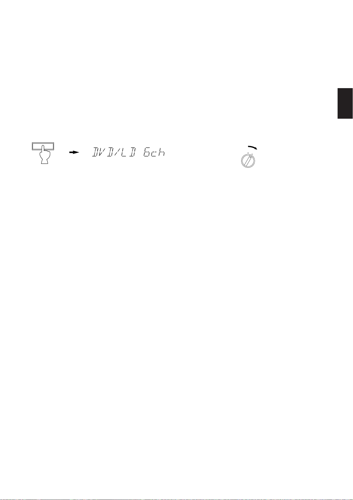
47
Français
Pour écouter une source décodée avec l’effet
numérique Dolby (AC-3) en reproduisant les
signaux entrés aux bornes 6CH DISCRETE
INPUT de cet appareil
A l’étape 3, sélectionner TV/DBS ou DVD/LD, puis appuyer
sur la touche 2CH/6CH de manière que l’indication “6ch”
apparaisse sur l’affichage. Les signaux parvenant du
décodeur numérique Dolby (AC-3), etc. branché aux bornes
6CH DISCRETE INPUT de cet appareil sont sélectionnés
comme signaux d’entrée.
Pour faire disparaître l’indication, appuyer à nouveau sur la
touche 2CH/6CH ou sélectionner une autre source d’entrée.
Remarque concernant la reproduction des signaux
discrets avec l’effet numérique Dolby (AC-3) décodé:
1.
Une enceinte centrale doit être incluse dans le système.
2.
Une enceinte pour woofer auxiliaire doit être inclus dans le
système.
* Brancher une enceinte pour woofer auxiliaire doté d’un
amplificateur incorporé à l’une des bornes SUBWOOFER
OUTPUT de cet appareil.
(Un subwoofer peut être raccordé à l’autre borne
SUBWOOFER OUTPUT.)
* Il est possible de ne pas utiliser un woofer auxiliaire. Dans
ce cas, il faut effectuer un réglage pour distribuer les
signaux au canal LFE aux bornes de sortie MAIN droite et
gauche du décodeur numérique Dolby (AC-3).
Pour plus de détails, se reporter au mode d’emploi du
décodeur numérique Dolby (AC-3).
Remarques
●
Lorsqu’on passe dans ce mode “6CH”, le processeur de
champ sonore numérique incorporé ne fonctionne pas et il
n’est pas possible d’effectuer le réglage du temps de retard.
●
Lorsque cet appareil est mis en mode “6CH”, aucun signal
ne parviendra à cet appareil si les bornes 6CH DISCRETE
INPUT de cet appareil ne sont pas raccordées.
Pour faire l’écoute de sons en reproduisant des
signaux entrés aux bornes INPUT (from
AMP/RECEIVER PREOUT) situées sur le
panneau arrière à partir de l’amplificateur
externe, etc.
1.
Régler le volume au minimum sur l’amplificateur externe.
2. Etablir l’alimentation électrique sur les appareils
audio/vidéo (y compris cet appareil) que l’on veut utiliser.
3. Mettre le sélecteur PROCESSOR SELECTOR situé sur le
panneau avant de cet appareil sur la position
“EXTERNAL”.
4. Enclencher la lecture de la source.
5. Augmenter progressivement le volume jusqu’au niveau
d’écoute désiré sur l’amplificateur externe, etc.
6. Le cas échéant, régler la balance, la tonalité, etc., sur
l’amplificateur externe, etc.
Remarque
Lorsqu’on ne désire pas utiliser les signaux entrés aux bornes
INPUT (from AMP/RECEIVER PREOUT) situées sur le
panneau arrière de l’appareil, veiller à ce que le sélecteur
PROCESSOR SELECTOR soit mis sur la position
“INTERNAL”.
2CH/6CH
INTERNAL
EXTERNAL
PROCESSOR
SELECTOR
Page 48

48
1 Sélectionner la source que l’on veut enregistrer.
2 Mettre en marche la source et tourner la commande
VOLUME afin de vérifier si la source choisie est bien la
bonne.
3 Enclencher l’enregistrement sur la platine à cassette
(ou magnétophone à minidisque, etc.) ou sur le
magnétoscope raccordé à cet appareil.
4 Si la platine à cassette (ou un magnétophone à
minidisque, etc.) est utilisée pour l’enregistrement, il est
possible de contrôler les sons enregistrés en appuyant
sur la touche TAPE (MD) MONITOR de manière que
l’indication “TAPE MON” s’allume sur l’affichage.
Remarques
●
Lors de l’étape 1, ne pas effectuer de sélection de source
d’entrée de manière que “6ch” apparaisse à l’affichage. Les
signaux entrés aux bornes 6CH DISCRETE INPUT de cet
appareil ne peuvent pas être enregistrés par une platine à
cassette, un magnétophone à minidisque ou un
magnétoscope.
●
Le DSP et la commande VOLUME n’affectent pas
l’enregistrement.
l6
20
28
40
60
l2
8
4
2
0
–dB
VOLUME
ENREGISTREMENT D’UNE SOURCE SUR UNE BANDE MAGNÉTIQUE
(OU UN MINIDISQUE)
2
NATURAL SOUND AV PROCESSOR/AMPLIFIER
DSP–E492
CINEMA DSP
POWER
VOLUME
l6
20
28
40
60
l2
8
4
2
0
–dB
DELAY/
CENTER/REAR
CENTER
MODE
TIME/LEVEL
INTERNAL
EXTERNAL
PRESET
kHz
MHz
MEMORY AUTO PTY HOLD
SLEEP
TAPE MONITOR
STEREO
ms dB
PRO LOGIC
ENHANCED
CONCERT
VIDEO
MONO
MOVIE
STADIUM
DISCO
ROCK CONCERT
CONCERT HALL
VCR DVD/LD
2CH
/
6CH
TV/DBS
TAPE (MD)
MONITOR
TUNER
(LINE 2)CD(LINE 1)
NORMAL
WIDE
PHANTOM
EFFECT OFF
PS
EON
INFO AFFAIRS SPORT
NEWS
RT CTPTY
0
20
l00
40 60
EFFECT
PRO LOGIC
ENHANCED MONO MOVIE STADIUM
PROCESSOR
SELECTOR
DISCO
ROCK CONCERT CONCERT HALLCONCERT VIDEO
1
4
VCR DVD/LD
2CH
/
6CH
TV/DBS
TAPE (MD)
MONITOR
TUNER
(LINE 2)
CD
(LINE 1)
VCR DVD/LD
2CH
/
6CH
TV/DBS
TAPE (MD)
MONITOR
TUNER
(LINE 2)
CD
(LINE 1)
Page 49

49
Français
Bref aperçu des programmes de champ sonore numérique
Une description sommaire des divers champs sonores produits par chacun des programmes du DSP est donnée ci-dessous. Ne
pas oublier que la plupart de ces champs sont la reproduction numérique exacte d’environnements acoustiques réels. Les données
de ces champs sonores ont été enregistrées sur les lieux mêmes en utilisant des équipements ultra-perfectionnés de mesure de
champ sonore.
Remarque
L’équilibre du niveau sonore des canaux entre les enceintes d’effet arrière gauche et droite peut varier selon le champ
sonore écouté. Ceci est dû au fait que la plupart de ces champs sonores reproduisent des environnements acoustiques
réels.
PROGRAMME CARACTERISTIQUES
Ce programme est utilisé pour la lecture de sources encodées avec le système ambiophonique Dolby.
PRO LOGIC
L’utilisation du système de traitement de signal numérique sophistiqué réduit la diaphonie, en dirigeant la
source sonore avec plus de douceur et de précision que les systèmes traditionnels.
Le champ sonore stable d’une salle de cinéma est ainsi recréé.
Ce programme est aussi utilisé pour la lecture de sources encodées avec le système d’effet
ambiophonique Dolby.
PRO LOGIC En améliorant les caractéristiques du système Logique Pro Dolby “Normal”, la technologie DSP simule le
ENHANCED système d’effet ambiophonique à enceintes multiples d’une salle de cinéma de 35 mm. Cet effet produit un
champ sonore de grande amplitude, et élargit l’univers sonore avec une image plus réaliste. Ce
programme est utilisé pour les films musicaux, ou pour les films dramatiques ou comiques.
Ce programme convient aux cassettes vidéo musicales et produit d’excellents vocaux par leur profondeur
CONCERT VIDEO et leur netteté. Pour les musiques d’opéra, les acoustiques particulières à l’orchestre et à la scène sont
parfaitement recréées, ce qui donne l’impression qu’on est soi-même dans la salle d’opéra.
Ce mode est spécialement conçu pour mettre en valeur les programmes de source mono. Comparée à un
MONO MOVIE
réglage strictement mono, l’image sonore créée dans ce mode est plus large et est perçue légèrement à
l’avant de la paire d’enceintes, en avance immédiate sur le son global. Ce mode convient particulièrement
aux anciens films, aux informations et dialogues mono.
STADIUM
Ce programme allonge considérablement les délais entre les sons directs et les sons d’effets, ce qui
permet de donner l’impression d’espace extraordinaire d’un grand stade.
DISCO
Ce programme reproduit l’environnement acoustique d’une disco d’une ville très animée. Le son est dense
et très concentré. Le son très énergétique donne une impression de proximité immédiate.
ROCK CONCERT
Ce programme convient parfaitement à la musique rock. On obtiendra un champ sonore très dynamique
et très vivant.
Avec ce programme, le centre semblera être profondément à l’arrière des enceintes principales, recréant
CONCERT HALL la dimension sonore d’une grande salle de concert. Ce champ sonore convient pour les musiques de
grands orchestres et d’opéra.
UTILISATION DU PROCESSEUR DE CHAMP SONORE
NUMERIQUE (DSP)
Cet appareil possède un processeur de champ sonore numérique à programmes multiples sophistiqué. Le processeur permet
d’étendre et de changer électroniquement la forme du champ sonore des sources audio et vidéo, reproduisant l’univers sonore
d’une salle de cinéma dans votre salle d’écoute. On peut créer un champ sonore d’excellente qualité en choisissant un programme
de champ sonore approprié (ceci dépend, bien entendu, du type d’enregistrement écouté), et en ajoutant les réglages désirés.
De plus, cet appareil est équipé d’un décodeur Logique Pro d’effet ambiophonique Dolby pour la reproduction à canaux multiples de
sources encodées de l’effet ambiophonique Dolby. Le fonctionnement du décodeur Logique Pro d’effet ambiophonique Dolby peut
être contrôlé en choisissant un programme de processeur de champ sonore numérique correspondant combinant un
fonctionnement du processeur de champ sonore numérique Yamaha et du décodeur Logique Pro d’effet ambiophonique Dolby.
Page 50

50
1 Effectuer les opérations 1, 2, 3, 4 et 5 de la section
“FONCTIONNEMENT DE BASE”, page 46.
2 Sélectionner le programme du processeur qui convient à
la source.
Le nom du programme sélectionné apparaît à l’affichage.
3 Régler, si on le souhaite, la durée de retard et le niveau
de sortie de chaque enceinte. (Voir, pour détails, les
descriptions correspondantes aux pages 51 et 52.)
Remarques
●
Il est possible de sélectionner un programme avec des
sources d’entrée individuelles.
Une fois qu’on a sélectionné un programme, celui-ci sera lié
à la source d’entrée sélectionnée à ce moment. Par
conséquent, lorsqu’on sélectionnera la source d’entrée
ultérieurement, le même programme sera automatiquement
rappelé.
●
Lorsqu’on souhaite annuler le programme de traitement de
champ sonore numérique, appuyer sur la touche EFFECT.
Les sons seront ceux d’un système stéréo normal à deux
canaux, sans effet ambiophonique.
●
Lorsque les programmes CONCERT VIDEO, MONO
MOVIE, STADIUM, DISCO, ROCK CONCERT ou
CONCERT HALL sont sélectionnés, aucun son n’est émis à
l’enceinte centrale.
●
Lorsqu’une source mono est reproduite avec DOLBY PRO
LOGIC ou DOLBY PRO LOGIC ENHANCED, aucun son
n’est émis aux enceintes principales et arrière. Le son n’est
entendu qu’à l’enceinte centrale. Toutefois, si le mode de
canal central est sur la position PHANTOM, les sons
normalement émis au canal central sont entendus aux
enceintes principales.
●
Pour sélectionner un programme DSP sur la télécommande,
mettre d’abord le processeur de champ sonore numérique
en circuit de manière qu’un nom de programme s’allume sur
l’affichage en appuyant sur la touche EFFECT.
Ensuite, sélectionner le programme DSP désiré en
appuyant sur le côté ou de la touche PROGRAM.
* Lorsqu’on appuie sur la touche PROLOGIC ou
ENHANCED, le processeur de champ sonore numérique
est mis en circuit et le programme correspondant est
directement sélectionné.
Reproduction d’une source en utilisant le processeur de champ sonore numérique
2
EFFECT
ON/OFF
PROLOGIC
ENHANCED
2
PRO LOGIC
ENHANCED MONO MOVIE
CONCERT VIDEO
REC/PAUSE
DIR BDIR A
PLAY
DISC
2CH/6CH VOLUME
PLAY
PRESET
A/B/C/D/E
–+
TIME/
LEVEL
TEST
EFFECT
PROGRAM
PROLOGIC
ENHANCED
–+
TAPE
A/B
ON/OFF
TUNER L2
CD L1
DELAY/CENTER
/REAR/SWFR
DVD/LD
VCR
TV/DBS
NATURAL SOUND AV PROCESSOR/AMPLIFIER
POWER
EFFECT
PRESET
MEMORY AUTO PTY HOLD
PS
PRO LOGIC
CINEMA DSP
DSP–E492
ms dB
kHz
MHz
TAPE MONITOR
PRO LOGIC
INFO AFFAIRS SPORT
ENHANCED
EON
NEWS
RT CTPTY
ENHANCED MONO MOVIE STADIUM
CONCERT
VIDEO
VCR DVD/LD
TAPE (MD)
MONITOR
CENTER
MODE
TV/DBS
2CH
/
6CH
TUNER
(LINE 2)CD(LINE 1)
DELAY/
CENTER/REAR
TIME/LEVEL
NORMAL
SLEEP
STEREO
WIDE
PHANTOM
EFFECT OFF
20
40 60
l00
0
DISCO
MONO
ROCK CONCERT
STADIUM
MOVIE
CONCERT HALL
DISCO
ROCK CONCERT CONCERT HALLCONCERT VIDEO
VOLUME
l6
20
l2
28
8
4
40
2
60
0
–dB
PROCESSOR
SELECTOR
INTERNAL
EXTERNAL
PRO LOGIC
PROGRAM
Page 51

51
Français
I est possible de régler le niveau de sortie des sons de
l’enceinte centrale, même si le niveau de sortie a déjà été réglé
lors du “REGLAGE DE LA BALANCE DES ENCEINTES”,
page 45.
1 Appuyer une fois ou plus sur la touche de manière que
l’indication “CENTER” apparaisse à l’affichage.
2 En maintenant enfoncé le côté “+” ou “–” de la touche
TIME/LEVEL, la valeur change continuellement.
On notera un léger temps d’arrêt sur le point préréglé
(0 dB).
Plage de commande: MIN, –20 à +10 dB
Remarques
●
Il est possible d’effectuer ce réglage seulement lorsque le
programme de champ sonore numérique DOLBY PRO
LOGIC ou DOLBY PRO LOGIC ENHANCED est
sélectionné, ou lorsque le mode de source d’entrée “6CH”
est sélectionné.
●
Une fois que le niveau de sortie a été réglé, cette valeur
restera la même pour les programmes de champ sonore
numérique mentionnés ci-dessus.
Réglage de la commande CENTER LEVEL (niveau de sortie centrale)
TIME/LEVEL
DELAY/CENTER
/REAR/SWFR
Réglable
Réglage de la commande REAR LEVEL (niveau de sortie arrière)
Il est possible de régler le niveau de sortie des sons émis aux
enceintes arrière, même s’il a déjà été réglé lors du
“REGLAGE DE LA BALANCE DES ENCEINTES”, page 45.
1 Appuyer une fois ou plus sur la touche de manière que
l’indication “REAR” apparaisse à l’affichage.
2 En maintenant enfoncé le côté “+” ou “–” de la touche
TIME/LEVEL, la valeur change continuellement.
On notera un léger temps d’arrêt sur le point préréglé
(0 dB).
Plage de commande: MIN, –20 à +10 dB
Remarques
●
Il est possible d’effectuer ce réglage seulement lorsque le
processeur de champ sonore numérique est en circuit, ou
lorsque le mode de source d’entrée “6CH” est sélectionné.
●
Une fois que le niveau de sortie a été réglé, cette valeur
restera la même pour tous les programmes de champ
sonore numérique.
TIME/LEVEL
Réglable
DELAY/CENTER
/REAR/SWFR
Page 52
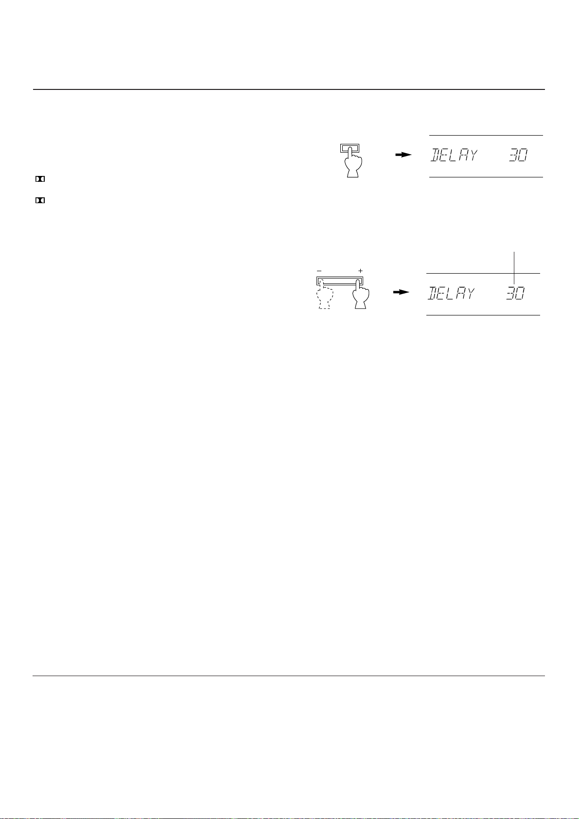
52
Il est possible de régler la différence de temps entre le début
des sons des enceintes principales et le début de l’effet sonore
des enceintes arrière.
Plus la valeur est grande, plus le son d’effet sera émis tard.
Ce réglage peut être effectué pour tous les programmes
individuellement.
PRO LOGIC : De 15 à 30 millisecondes
(Valeur préréglée: 20 millisecondes)
PRO LOGIC : De 15 à 30 millisecondes
ENHANCED (Valeur préréglée: 20 millisecondes)
CONCERT VIDEO : De 1 à 100 millisecondes
(Valeur préréglée: 28 millisecondes)
MONO MOVIE : De 1 à 100 millisecondes
(Valeur préréglée: 20 millisecondes)
STADIUM : De 1 à 50 millisecondes
(Valeur préréglée: 45 millisecondes)
DISCO : De 1 à 100 millisecondes
(Valeur préréglée: 14 millisecondes)
ROCK CONCERT : De 1 à 100 millisecondes
(Valeur préréglée: 17 millisecondes)
CONCERT HALL : De 1 à 100 millisecondes
(Valeur préréglée: 30 millisecondes)
1 Appuyer une fois ou plus sur la touche de manière que
l’indication “DELAY” apparaisse à l’affichage.
2 En maintenant enfoncées le côté “+” ou “–” de la touche
TIME/LEVEL, la valeur de retard change continuellement.
Il y a un léger temps d’arrêt lorsque la valeur atteint la
valeur préréglée.
Remarques
●
Selon la source utilisée, l’ajout de trop de retard pourra
dénaturer l’effet sonore.
●
Lorsqu’on appuie sur la touche TIME/LEVEL, le son est
momentanément interrompu.
Remarque
Les derniers réglages de temps de retard, de niveau de sortie
centrale et de niveau de sortie arrière demeurent dans la
mémoire de l’appareil, même après sa mise hors-circuit.
Cependant, si le cordon d’alimentation de l’appareil reste
débranché au-delà d’une semaine, ces réglages retourneront
automatiquement aux valeurs préréglées en usine.
TIME/LEVEL
Réglable
ms
ms
DELAY/CENTER
/REAR/SWFR
Réglage de la commande DELAY TIME (durée de retard)
Page 53

53
Français
Si l’appareil ne fonctionne pas correctement, avant de conclure qu’il est en panne, le vérifier selon la liste suivante de problèmes
possibles. Cette liste donne des détails sur les remèdes que vous pouvez appliquer vous-même sans avoir à appeler un
spécialiste. Si vous avez quelque doute ou question, consulter votre revendeur officiel YAMAHA le plus proche.
EN CAS DE DIFFICULTE
AmplificateurAutres
Télécommande
SYMPTOME
L’appareil ne se met pas sous tension lorsqu’on
appuie sur l’interrupteur POWER, ou se met
soudain hors tension après la mise sous
tension.
Pas de son ou pas d’image.
Le son se coupe soudainement.
Les sons ne sont émis aux enceintes que d’un
seul côté.
Le son “bourdonne”.
Il est impossible d’augmenter le niveau de
volume, ou il y a une distorsion du son.
Les enceintes principales n’émettent aucun son.
Les enceintes arrière n’émettent aucun son.
L’enceinte centrale n’émet aucun son.
La télécommande ne fonctionne pas.
Les sons se dégradent lorsqu’on écoute avec un
casque relié à un lecteur de disque compact ou
à une platine à cassette raccordés à cet
appareil.
Parasites en provenance du téléviseur ou du
tuner voisin.
CAUSE
Le cordon d’alimentation n’est pas branché ou ne
l’est pas complètement.
L’interrupteur IMPEDANCE SELECTOR situé sur le
panneau arrière n’est pas placé exactement à
l’extrémité gauche ou droite.
Mauvais raccordement des câbles de sortie.
Sélection d’entrée incorrecte.
Le sélecteur PROCESSOR SELECTOR situé sur le
panneau avant de l’appareil est mis sur la position
“EXTERNAL”.
Les connexions des enceintes ne sont pas correctes.
Le circuit de protection s’est déclenché dû à un
court-circuit, etc.
Mauvais raccordement des câbles.
Mauvais raccordement des câbles.
Le contact n’est pas établi sur l’appareil branché
aux bornes REC OUT de cet appareil.
Le volume est réglé au niveau minimum sur
l’amplificateur externe entraînant les enceintes
principales.
Mauvais raccordement des câbles.
Le niveau de sortie des enceintes arrière est réglé
sur 0.
La source mono est lue en mode DOLBY PRO
LOGIC ou DOLBY PRO LOGIC ENHANCED.
Le niveau de sortie de l’enceinte centrale est réglé
sur 0.
Le sélecteur de mode de canal central est sur la
position PHANTOM.
Mauvaise sélection du programme de champ sonore.
Le détecteur de télécommande de l’appareil principal
est exposé à la lumière directe du soleil (ou d’une
lampe fluorescente de type inverseur, etc.).
Les piles de cette télécommande sont trop faibles.
Le contact n’est pas établi sur cet appareil.
Cet appareil est trop près des appareils en question.
REMEDE
Bien brancher le cordon d’alimentation.
Placer l’interrupteur exactement sur l’extrémité
gauche ou droite.
Raccorder correctement les câbles. Si le problème
persiste, les câbles sont peut-être en mauvais état.
Sélectionner une source d’entrée correcte au
moyen des sélecteurs d’entrée.
Lorsqu’on ne désire pas utiliser les signaux entrés
aux bornes INPUT (from AMP/RECEIVER
PREOUT) situées sur le panneau arrière de
l’appareil, veiller à ce que le sélecteur
PROCESSOR SELECTOR soit mis sur la position
“INTERNAL”.
Effectuer des connexions correctes.
Eteindre et rallumer l’appareil pour remettre à zéro
le circuit de protection.
Raccorder correctement les câbles. Si le probléme
persiste, les câbles sont peut-être en mauvais état.
Raccorder fermement les prises audio. Si le problème
persiste, le câble est peut-être en mauvais état.
Mettre l’appareil concerné sous tension.
Augmenter le volume sur l’amplificateur externe.
Raccorder correctement les câbles. Si le probléme
persiste, les câbles sont peut-être en mauvais état.
Augmenter le niveau de sortie sur les enceintes
arrière.
Sélectionner un autre programme approprié à la
source mono.
Augmenter le niveau de sortie sur I’enceinte
centrale.
Sélectionner la position NORMAL ou WIDE.
Choisir un programme adéquat.
Changer la position de l’appareil principal.
Eloigner le téléviseur.
Mettre cet appareil sous tension.
Eloigner cet appareil des appareils en question.
Page 54

54
SECTION AUDIO
Puissance de sortie minimum RMS par canal
8 ohms, 20 Hz à 20 kHz, 0,04% de DHT (lorsque 3 canaux
sont entraînés:)
6CH DISCRETE INPUT à CENTER ..............................60W
6CH DISCRETE INPUT à REAR..........................60W+60W
Puissance dynamique par canal
(Mesurée par la méthode IHF Dynamic Headroom)
[Modèles pour les Etats-Unis et le Canada]
8/6/4/2 ohms..............................................110/130/150/165W
[Modèles pour l’Europe, le Royaume-Uni, l’Australie et
général]
8/6/4/2 ohms..............................................115/140/160/175W
Puissance de sortie standard DIN par canal [Modèle pour
l’Europe seulement]
4 ohms, 1 kHz, 0,7% de DHT
CENTER, REAR.............................................................70W
Puissance IEC [Modèle pour l’Europe seulement]
8 ohms, 1 kHz, 0,1% de DHT (lorsque 3 canaux sont
entraînés:)
CENTER, REAR.............................................................75W
Largeur de bande de puissance
8 ohms, 30W, 0,1% de DHT
CENTER, REAR............................................10 Hz à 60 kHz
Facteur d’amortissement
8 ohms, 1 kHz
CENTER, REAR..................................................200 ou plus
Sensibilité d’entrée/Impédance d’entrée
6CH DISCRETE INPUT
à MAIN PRE OUT (1V)............................150 mV/47 k-ohms
à CENTER SP OUT (60W)......................150 mV/47 k-ohms
à REAR SP OUT (60W) ..........................150 mV/47 k-ohms
à SUBWOOFER PREOUT (3,5V)...........100 mV/30 k-ohms
Niveau de sortie/impédance de sortie
REC OUT..................................................150 mV/2,7 k-ohms
MAIN PRE OUT ...............................................1V/2,7 k-ohms
CENTER PRE OUT .........................................2V/1,2 k-ohms
REAR PRE OUT ..............................................2V/1,2 k-ohms
SUBWOOFER..................................................4V/1,2 k-ohms
Tension de sortie maximale
20 Hz à 20 kHz, 0,01% de DHT
MAIN PRE OUT .............................................................1,6V
Réponse en fréquence
CENTER, REAR
(20 Hz à 20 kHz) ............................0±0,5 dB
MAIN PRE OUT
(20 Hz à 20 kHz).............................0±0,5 dB
SUBWOOFER PRE OUT
(150 Hz).................................–3 dB
Distorsion harmonique totale
6CH DISCRETE INPUT
à MAIN PRE OUT (20 Hz à 20 kHz, 1V)....0,006% ou moins
à CENTER SP OUT (20 Hz à 20 kHz, 50W/8 ohms)
...................................................................0,015% ou moins
à REAR SP OUT (1 kHz, 50W/8 ohms).....0,015% ou moins
à SUBWOOFER PRE OUT (50 Hz, 3,5V)
...................................................................0,015% ou moins
Rapport signal/bruit (IHF réseau A) (court-circuitée)
6CH DISCRETE INPUT
à MAIN PRE OUT............................................95 dB ou plus
à CENTER SP OUT.........................................90 dB ou plus
à REAR SP OUT .............................................90 dB ou plus
Bruit résiduel (IHF réseau A)
6CH DISCRETE INPUT
à MAIN PRE OUT........................................5.0 µV ou moins
à CENTER SP OUT....................................270 µV ou moins
à REAR SP OUT ........................................270 µV ou moins
Séparation des canaux (Vol. –30 dB)
6CH DISCRETE INPUT à MAIN PRE OUT
(entrée court-circuiteé 5,1 k-ohms)
1 kHz................................................................70 dB ou plus
10 kHz..............................................................50 dB ou plus
GENERALES
Alimentation
[Modèles pour les Etats-Unis et le Canada]
.......................................................................CA 120V, 60 Hz
[Modèles pour l’Europe et le Royaume-Uni]
.......................................................................CA 230V, 50 Hz
[Modèle pour l’Australie].................................CA 240V, 50 Hz
[Modèle pour général] ..........CA 110/120/220/240V, 50/60 Hz
Consommation
[Modèle pour les Etats-Unis]...........................................160W
[Modèle pour le Canada]....................................160W/220 VA
[Modèles pour l’Europe, le Royaume-Uni, l’Australie
et général].......................................................................200W
Consommation maximale
[Modèle général seulement] ...........................................600W
Prise CA
PRISE COMMUTEE..............................................100W max.
Dimensions (L x H x P)...........................435 x 126 x 389,5 mm
Poids.................................................................................8,5 kg
Accessoires....................................Emetteur de télécommande
Piles
Caractéristiques techniques modifiables sans préavis.
CARACTERISTIQUES TECHNIQUES
Page 55

YAMAHA ELECTRONICS CORPORATION, USA 6660 ORANGETHORPE AVE., BUENA PARK, CALIF. 90620, U.S.A.
YAMAHA CANADA MUSIC LTD. 135 MILNER AVE., SCARBOROUGH, ONTARIO M1S 3R1, CANADA
YAMAHA ELECTRONIK EUROPA G.m.b.H. SIEMENSSTR. 22-34, 25462 RELLINGEN BEI HAMBURG, F.R. OF GERMANY
YAMAHA ELECTRONIQUE FRANCE S.A. RUE AMBROISE CROIZAT BP70 CROISSY-BEAUBOURG 77312 MARNE-LA-VALLEE CEDEX02, FRANCE
YAMAHA ELECTRONICS (UK) LTD. YAMAHA HOUSE, 200 RICKMANSWORTH ROAD WATFORD, HERTS WD1 7JS, ENGLAND
YAMAHA SCANDINAVIA A.B. J A WETTERGRENS GATA 1, BOX 30053, 400 43 VÄSTRA FRÖLUNDA, SWEDEN
YAMAHA MUSIC AUSTRALIA PTY, LTD. 17-33 MARKET ST., SOUTH MELBOURNE, 3205 VIC., AUSTRALIA
Printed in Malaysia VY82150
 Loading...