


DSP UNIT
SERVICE MANUAL
PA
011509
CONTENTS
REVISED PAGE LIST ··························································· 2-1
SPECIFICATIONS································································· 3-1
PANEL LAYOUT···································································· 3-2
DIMENSIONS········································································ 3-4
CONNECTOR CIRCUIT DIAGRAM ········································· 4
DISASSEMBLY PROCEDURE················································· 6
LSI PIN DESCRIPTION·························································· 10
IC BLOCK DIAGRAM ····························································· 17
CIRCUIT BOARDS································································· 21
INSPECTION·········································································· 42
TEST PROGRAM··································································· 43
ERROR MESSAGES······························································ 57
BLOCK DIAGRAM·································································· 58
PARTS LIST
CIRCUIT DIAGRAM
HAMAMATSU, JAPAN
0.27K-
****
Printed in Japan '00.09

DSP1D
REVISED PAGE LIST
ITEM
SPECIFICATIONS
PANEL LAYOUT
DIMENSIONS
CONNECTOR CIRCUIT DIAGRAM
CIRCUIT BOARDS IFC1 Circuit Board
<
PARTS LIST>
ITEM
OVERALL ASSEMBLY
JK BOX ASSEMBLY
ELECTRICAL PARTS
<
CIRCUIT DIAGRAM>
ITEM
PAGE
3-1
3-2,3-3
3-4
4
35
PAGE
2~ 5
6
7~24
PAGE
ITEM
INSPECTION
TEST PROGRAM
ERROR MESSAGES
BLOCK DIAGRAM
ITEM
PAGE
42
43~56
57
58~93
PAGE
CIB CIRCUIT DIAGRAM 003
005
006
008
009
012
EDB CIRCUIT DIAGRAM 002
004
005
011
EMB CIRCUIT DIAGRAM 002
003
005
007
009
010
011
GDB CIRCUIT DIAGRAM 002
004
006
007
008
012
016
IDB CIRCUIT DIAGRAM 004
005
4
6
7
9
10
13
14
16
17
23
25
26
28
30
32
33
34
35
37
39
40
41
45
49
53
54
IDB CIRCUIT DIAGRAM 017
018
IFC1 CIRCUIT DIAGRAM 005
006
007
008
JK1 CIRCUIT DIAGRAM 002
003
004
JK2 CIRCUIT DIAGRAM 002
003
004
JK3 CIRCUIT DIAGRAM 002
003
005
JK4 CIRCUIT DIAGRAM 004
JK5 CIRCUIT DIAGRAM 2/2
JK6 CIRCUIT DIAGRAM 1/2
2/2
PDB CIRCUIT DIAGRAM 002
004
010
016
017
018
66
67
72
73
74
75
76
77
78
79
80
81
82
84
85
88
90
91
92
97
99
105
111
112
113
2-1

DSP1D
IMPORTANT NOTICE
This manual has been provided for the use of authorized Yamaha Retailers and their service personnel. It has been assumed that
basic service procedures inherent to the industry, and more specifically Yamaha Products, are already known and understood by
the users, and have therefore not been restated.
WARNING: Failure to follow appropriate service and safety procedures when servicing this product may result in personal
injury, destruction of expensive components and failure of the product to perform as specified. For these
reasons, we advise all Yamaha product owners that all service required should be performed by an authorized
Yamaha Retailer or the appointed service representative.
IMPORTANT: This presentation or sale of this manual to any individual or firm does not constitute authorization, certification,
recognition of any applicable technical capabilities, or establish a principal-agent relationship of any form.
The data provided is belived to be accurate and applicable to the unit(s) indicated on the cover. The research engineering, and
service departments of Yamaha are continually striving to improve Yamaha products. Modifications are, therefore, inevitable and
changes in specification are subject to change without notice or obligation to retrofit. Should any discrepancy appear to exist,
please contact the distributor's Service Division.
WARNING: Static discharges can destroy expensive components. Discharge any static electricity your body may have
accumulated by grounding yourself to the ground bus in the unit (heavy gauge black wires connect to this bus).
IMPORTANT: Turn the unit OFF during disassembly and parts replacement. Recheck all work before you apply power to the
unit.
LITHIUM BATTERY HANDLING
This product uses a lithium battery for memory back-up.
WARNING: Lithium batteries are dangerous because they can be exploded by improper handling. Observe the following
precautions when handling or replacing lithium batteries.
Leave lithium battery replacement to qualified service personnel.
Always replace with batteries of the same type.
When installing on the PC board by soldering, solder using the connection terminals provided on the battery cells.
Never solder directly to the cells. Perform the soldering as quickly as possible.
Never reverse the battery polarities when installing.
Do not short the batteries.
Do not attempt to recharge these batteries.
Do not disassemble the batteries.
Never heat batteries or throw them into fire.
ADVARSEL!
Lithiumbatteri-Eksplosionsfare ved fejlagtig håndtering. Udskiftning må kun ske med batteri af samme fabrikat og type. Levér det
brugte batteri tilbage til leverandøren.
VARNING
Explosionsfara vid felaktigt batteribyte.
Använd samma batterityp eller en ekvivalent typ som rekommenderas av apparattillverkaren.
Kassera använt batteri enligt fabrikantens instruktion.
VAROITUS
Paristo voi räjähtää, jos se on virheellisesti asennettu.
Vaihda paristo ainoastaan laitevalmistajan suosittelemaan tyyppiin.
Hävitä käytetty paristo valmistajan ohjeiden mukaisesti.
The following information complies with Dutch Official Gazette 1995. 45; ESSENTIALS OF ORDER ON THE COLLECTION OF
BATTERIES.
• Please refer to the diassembly procedure for the removal of Back-up Battery.
• Leest u voor het verwijderen van de backup batterij deze beschrijving.
WARNING: CHEMICAL CONTENT NOTICE!
The solder used in the production of this product contains LEAD. In addition, other electrical/electronic and/or plastic (where
applicable) components may also contain traces of chemicals found by the California Health and Welfare Agency (and possibly
other entities) to cause cancer and/or birth defects or other reproductive harm.
DO NOT PLACE SOLDER, ELECTRICAL/ELECTRONIC OR PLASTIC COMPONENTS IN YOUR MOUTH FOR ANY REASON
WHAT SO EVER!
Avoid prolonged, unprotected contact between solder and your skin! When soldering, do not inhale solder fumes or expose eyes
to solder/flux vapor!
If you come in contact with solder or components located inside the enclosure of this product, wash your hands before handling
food.
WARNING
Components having special characteristics are marked and must be replaced with parts having specification equal to those
originally installed.
2-2

SPECIFICATIONS
DSP1D
Sampling frequency
Power supply
Power consumption
Dimensions (W x H x D)
Weight
Operating temperature
Fan circuit
Accessories
Digital I/Os
I/O connectors
DIGITAL I/O INPUT 1 –10
DIGITAL I/O OUTPUT 1 – 6
DIGITAL I/O CASCADE IN, OUT
DIGITAL I/O CONSOLE I/O 1, 2
CONTROL I/O CONSOLE 1 IN, OUT
CONTROL I/O CONSOLE 2 IN, OUT
REMOTE RS-422
GPI
TIME CODE IN
MIDI IN, OUT, THRU
PC CONTROL RS-232-C
PC CONTROL USB
WORD CLOCK IN
WORD CLOCK OUT
<External sync> 39.69 kHz – 50.88 kHz
<Internal sync> 44.1 kHz, 48 kHz
USA and Canada: 120 V, 60 Hz
Others: 230 V, 50 Hz
170 W
480 mm x 408.7 mm x 460.8 mm
33 kg
10 – 35˚C
always fixed
power cable 2.5 m x 1
Level
RS-422
RS-422
RS-422
RS-422
–0.225V — –1.825V/50 Ω
–0.225V — –1.825V/50 Ω
RS-422
C-MOS IN, Open collector OUT
1 pin: 150mA, 8pin total: 500mA
SMPTE format, Nominal –10 dB/10 kΩ
MIDI format
RS-232-C
0V — 3.3V
TTL/75 Ω (ON/OFF)
TTL/75 Ω
Type
D-sub, half-pitch, 68-pin connector (female) x 10
D-sub, half-pitch, 68-pin connector (female) x 6
D-sub, half-pitch, 68-pin connector (female) x 2
D-sub, half-pitch, 68-pin connector (female) x 2
BNC connector x 2
BNC connector x 2
D-sub, 9-pin connector (female)
D-sub, 25-pin connector (female)
XLR-3-31 type connector
5-pin DIN connector x 3
D-sub, 9-pin connector (male)
B type USB connector
BNC connector
BNC connector
Slots (for IDB1D board)
Unit
DPS1D
DPS1D-EX
* The DSP1D has an empty slot available for the IDB1D board.
INPUT 1-48 & ST IN 1-4 *
INPUT 1-96 & ST IN 1-8 (DSP1D + IDB1D for expansion)
Input channel
IMPORTANT NOTICE FOR THE UNITED KINGDOM
Connecting the Plug and Cord
IMPORTANT. The wires in this main lead are coloured in
accordance with the following code:
BLUE: NEUTRAL
BROWN: LIVE
As the colours of the wires in the main lead of this apparatus may not
correspond with the coloured markings identifying the terminals in
your plug, proceed as follows:
The BLUE wire must be connected to the terminal that is marked with
the letter N (or coloured BLACK).
The BROWN wire must be connected to the terminal that is marked
with the letter L (or coloured RED).
Be certain that neither core is connected to the earth terminal of the
three pin plug.
3-1

POWER
ON/ OFF
A B
ENGINE ID
1 2
CONTROL I/O
48CH 96CH
INPUT
CONFIGURATION
POWER
ON/ OFF
A B
ENGINE ID
1 2
CONTROL I/O
48CH 96CH
INPUT
CONFIGURATION
22
22
IN
OUT
IN
2
OUT
IN
1
1IN531 97531
2 OUT 6 4 2 10 8 6 4 2
OUT
THRU
PC
CONTROL
WORD CLOCK
TIME CODE IN
GPI
RS-422
REMOTE
IN
OUT
OFF
ON
RS-232-C
USB
75
MIDI
OUTPUT INPUT
CONTROL I/O
CONSOLE
CONSOLE
I/O
CASCADE
DIGITAL I/O
1 IN531 975 31
2 OUT 6 4 2 10 8 6 4 2
OUTPUT INPUT
CONSOLE
I/O
CASCADE
DIGITAL I/O
22
22
IN
OUT
IN
2
OUT
IN
1
OUT
THRU
PC
CONTROL
WORD CLOCK
TIME CODE IN
GPI
RS-422
REMOTE
IN
OUT
OFF
ON
RS-232-C
USB
75
MIDI CONTROL I/O
CONSOLE
1
2
3
4
5
6
7
8
9
10
11
16
12 13 14 15
1
ENGINE ID A/B indicators
2
CONTROL I/O 1/2 indicators
3
INPUT CONFIGURATION 48CH/96CH indicators
4
POWER ON/OFF switch
5
MIDI IN/OUT/THRU connectors
6
PC CONTROL RS-232-C/USB ports
7
WORD CLOCK IN jack, 75 ON/OFF
switch, and WORD CLOCK OUT jack
PANEL LAYOUT
Front Panel
Rear Panel
DSP1D
3-2

8
CONSOLE 1, 2 IN/OUT jacks
9
REMOTE RS-422 connector
10
GPI connector
11
TIME CODE IN connector
12
CONSOLE I/O 1, 2 slots
13
CASCADE IN, OUT slots
14
OUTPUT 1–6 slot
15
INPUT 1–10 slot
16
Ground connector
DSP1D
3-3
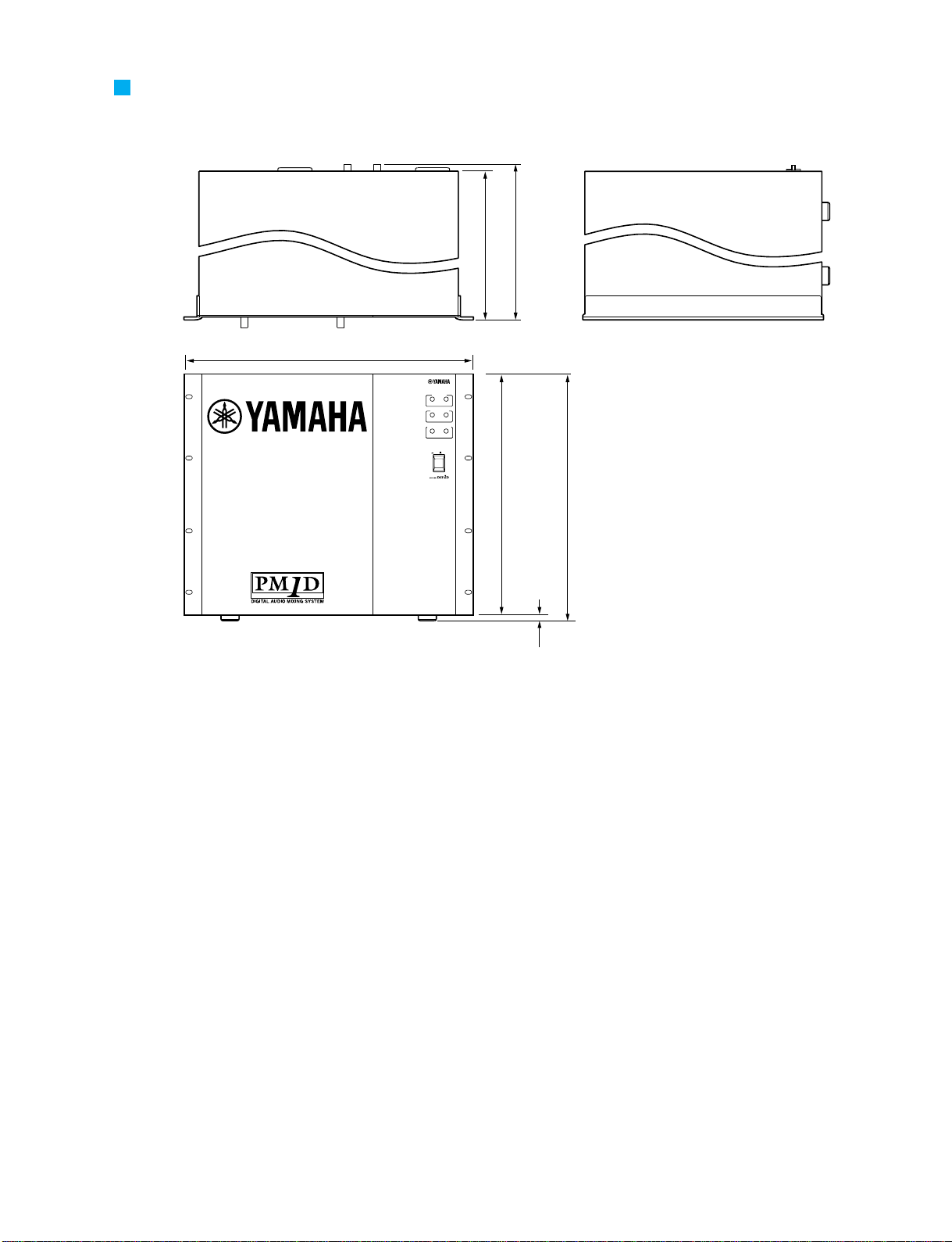
DIMENSIONS
POWER
ON/ OFF
A B
ENGINE ID
1 2
CONTROL I/O
48CH 96CH
INPUT
CONFIGURATION
460.8
450
480
399.2
408.7
9.5
DSP1D
Unit: mm
3-4

[1][2][3][5][6][7] [4][8][9][10][1][2][3][4][5][6][IN][OUT][1][2]
[INPUT][OUTPUT][CASCADE]
[CONSOLE I/O]
[CONTROL I/O]
[CONSOLE]
[1]
[2]
[REMOTE]
[GPI]
[TIME CODE IN]
[DIGITAL I/O]
[POWER]
[ON/OFF]
FOR DSP1D-EX
[IN]
[OUT]
[IN]
[OUT]
[RS-422]
[MIDI]
[PC CONTROL]
[WORD CLOCK]
[IN]
[OUT]
[THRU]
[RS-232-C]
[USB]
[IN][
75
]
[OUT]
[ON]
[OFF]
[CONTROL I/O]
[ENGINE ID]
[INPUT CONFIGURATION]
[A] [B]
[1] [2]
[48CH] [96CH]
POWER UNIT
FAN
8P
CN200
3P
CN1
CN809
3P
CN300
2P
CN8
10P
CN101
50P
CN802
50P
CN801
4P
CN604
4P
CN504
4P
CN404
4P
CN304
4P
CN204
4P
CN104
CIB
EMB
EDB
IDB
IDB
GDB
PDB
JK1
JK1
JK1
JK1
JK1
JK2
JK2
JK2
JK3
JK4
JK5
JK6
LED2
PSB2
MB11
IFC1
**
************
**
6P
CN9
8P
CN7
8P
CN6
8P
CN5
8P
CN4
9P
CN3
4P
CN10
8P
CN803
CN103
96P
CN703
CN102
96P
CN702
CN101
96P
CN701
CN103
96P
CN603
CN102
96P
CN602
CN101
96P
CN601
CN652
96P
CN503
CN651
96P
CN502
CN650
96P
CN501
CN3
96P
CN403
CN2
96P
CN402
CN1
96P
CN401
CN3
96P
CN303
CN2
96P
CN302
CN1
96P
CN301
CN904
96P
CN203
CN903
96P
CN202
CN902
96P
CN201
CN902
96P
CN103
CN901
96P
CN102
CN101
96P
CN102
CN102
96P
CN102
CN103
96P
CN102
CN104
96P
CN102
CN201
96P
CN102
CN202
96P
CN102
CN203
96P
CN102
CN301
96P
CN102
CN302
96P
CN102
CN303
96P
CN100
CN811
3P
CN810
96P
CN100
CN900
96P
CN101
CN100
96P
CN102
2P
FG
50P
CN901
50P
CN900
50P
CN950
14P
CN808
30P
CN801
30P
CN802
50P
CN807
50P
CN806
4P
CN105
4P
CN305
4P
CN505
4P
CN605
50P
CN804
50P
CN803
3P
CN405
50P
CN805
50P
CN952
50P
CN955
50P
CN954
50P
CN956
30P
CN951
30P
CN953
14P
CN957
KEC-92539-2
1
DSP1D
CONNECTOR CIRCUIT DIAGRAM
4
 Loading...