

DME Setup Manual
Version 4.0
This manual describes the process of setting up a DME system, from making the initial DME processor settings (DME64N / DME24N / DME8i-C / DME8o-C / DME4io-C / DME8i-ES / DME8o-ES / DME4io-ES) to synchronizing with the DME Designer application installed on a computer.
- In this document the term "DME" will refer to the DME64N, DME24N, DME8i-C, DME8o-C, DME4io-C, DME8i-ES, DME8o-ES and DME4io-ES, while the term "DME Satellite" will refer only to the DME8i-C, DME8o-C, DME4io-C, DME8i-ES, DME8o-ES and DME4io-ES.
- For details about the DME units refer to the manual supplied with the specific device, and for details about the DME Designer application refer to the pdf-format DME Designer manual.
- If you will be using CobraNet™ for audio connections, the required bundle numbers and related settings must be made via the DME Designer application.
- If you will be using EtherSound™ for audio connections, the routing and other EtherSound settings must be made via the AuviTran AVSESMonitor software available from the AuviTran website:
Version Compatibility
- DME Designer cannot be used to upgrade DME firmware version 3.5 or earlier to version 3.8 or later (this does not apply to the SP2060 or ICP1). Contact your Yamaha dealer or service center for this type of upgrade.
- DME Designer cannot be used to downgrade DME firmware version 3.8 or later to version 3.5 or earlier (this does not apply to the SP2060 or ICP1). Contact your Yamaha dealer or service center for this type of downgrade.
- DME firmware versions 3.8 or later cannot be written using DME Designer version 3.5 or earlier.
- DME firmware versions 4.0 or later are required to use DME Designer versions 4.0 or later.
Setup Flow
Software Installation (page 3)
■ Install DME Designer and DME-N Network Driver (page 5)
■ USB-MIDI Driver Installation (page 5)
| Basic Setup (page 7) | Advanced Setup (page 13) |
|---|---|
|
|
|
|
In-depth Information on DME Units (page 20)
Connecting to External Controllers
This section covers connection to remote controllers via Ethernet or GPI.
Setting up DME64N/24N Networks via Panel Operations
Describes how DME64N/24N network settings can be made via the control panel.
Related web site on DME series and peripherals
This section serves as a guide to online information on Speaker Processor Components library data, Mini-YGDAI cards, and touch-panel controllers (AMX/Creston).
DME-N Network Driver Setup Details (page 23)
Troubleshooting & Tips (page 26)
Software Installation
Begin by downloading the DME Designer Combo Installer and the USB-MIDI Driver from the "Downloads" page on the Yamaha Pro Audio website
(http://www.yamahaproaudio.com/downloads/firm_soft/index.html).
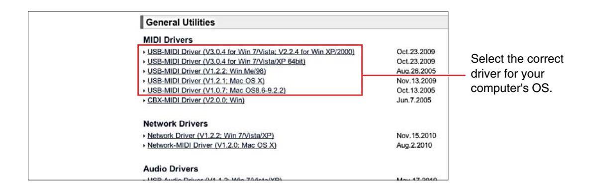
Select and download the appropriate driver for your computer's operating system.
DINOTE DME Designer V4.0 supports Windows7, Windows Vista, and Windows XP.
Minimum System Requirements
.
| OS | Windows 7:Ultimate / Professional / Home PremiumWindows Vista:Ultimate / Business / EnterpriseWindows XP:Professional / Home Edition |
|---|---|
| Hard Disk | 300MB or more |
| Display | 1280 x 1024 pixels or higher; High Color (16-bit) or higher |
| Other |
Pointing device such as a mouse
Ethernet (100Base-TX/10Base-T) port or USB port |
Windows Vista / Windows 7
| CPU | 32bit: 1.4GHz or higher Intel Core/Pentium/Celeron family processor 64bit: Intel 64 compatible processor |
|---|---|
| Available Memory | 1GB or more (2GB or more on Windows 7 64-bit) |
Windows XP
| CPU | 1GHz or higher Intel Core/Pentium/Celeron family processor |
|---|---|
| Available Memory | 256MB or more |
The system requirements described above are applied to the DME Designer version 4.0.0. Keep in mind that the software is often updated and the system requirements are subject to change. You can check the latest version information and its system requirements at the following website.
http://www.vamahaproaudio.com/
The system requirements may differ slightly depending on the particular computer.
Disable any power-saving mode on the computer.
When using the Windows Vista operating system, use only USB-MIDI Driver V3.0 or later, and DME-N Network Driver V1.2 or later
When using the Windows 7 operating system, use only USB-MIDI Driver V3.0.4 or later, and DME-N Network Driver V1.2.1 or later.
Download the DME Designer Combo Installer
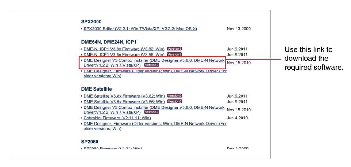
ENOTE The DME-N Network Driver can be downloaded individually, but the DME Designer Combo Installer allows you to download and install both DME Designer and the DME-N Network Driver in one operation.
DME Designer:
DME system settings can be made using this dedicated application.
ENOTE DME designer can be used in online mode even if a DME unit is not connected.
DME-N Network Driver:
This driver is needed in order for your computer and DME unit(s) to be connected via Ethernet.
Download the USB-MIDI Driver
This driver is needed in order for your computer and a DME unit to be connected using a USB cable.
When each has been downloaded, please expand it and place the expanded folder in an easy-to-find location such as your desktop.
Then, follow the steps described below in order to install the software.
Install DME Designer and DME-N Network Driver
Follow the procedure outlined below to install the DME Designer application and the DME-N Network Driver using the DME Designer Combo Installer.
| DME Designer + DME-N Net | work Driver Ver.3.0.0 | × |
|---|---|---|
|
Welcome to the InstallShield Wizard for DME
Designer Combo |
||
| Please quit all applications. | ||
| < Back Next > Cance |
After the downloaded compressed file is properly extracted, double-click the "setup.exe" file.
The setup wizard for the DME Designer Combo Installer will be displayed.
2 Execute the installation by following the directions appearing on the screen.
DME Designer will be installed first of all, followed by the DME-N Network Driver.
USB-MIDI Driver Installation
- Disconnect all USB devices from the computer except for the mouse and computer keyboard.
- 2 Start the computer and use the "Administrator" account to log on Windows.
Close all applications and windows that are open.
- 3 Turn off the power of the DME unit.
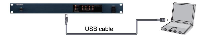
- 4 Connect the USB connector of the computer to the USB TO HOST connector of the DME unit with a standard USB cable.
Do not use a USB hub for connecting multiple USB devices.
5 Turn on the power of the DME unit(s).
6 When the "Found New Hardware Wizard" window appears, click [Cancel].
ENDIE This screen will not appear on Windows 7. When the message "Device driver software was not successfully installed." appears, continue the installation procedure.
7 After the downloaded compressed file is properly extracted, double-click the file "setup.exe."
The "Preparing to install" window appears. The next window will appear after finishing this preparation.
(Windows Vista/Windows 7) If the "User Account Control" window appears, click [Continue] or [Yes].
BNOTE If a DME Designer or DME-N Network Driver version other than the version being installed is already present, it will be uninstalled before the new installation begins. In this case it will be necessary to restart the computer after the existing software has been uninstalled. In all cases it will be necessary to restart the computer after the new software has been installed. Follow the on-screen instructions.
On some computers, it may take a few minutes before this screen appears.
8 When the "Welcome to the InstalShield Wizard for Yamaha USB-MIDI Driver" window appears, click [Next].
When the number of installed USB-MIDI drivers exceeds the Windows OS limit (10 instances) an error message will appear. In this case reinstall the Yamaha USB-MIDI Driver after uninstalling any unnecessary USB-MIDI drivers (page 28).
If the warning message below appears during the installation, click [Yes], [Continue Anyway], or [Install].
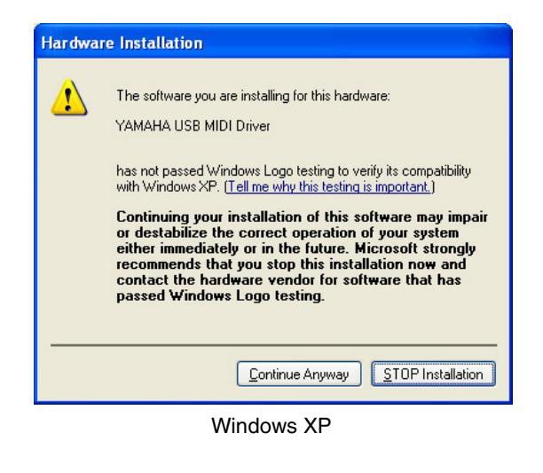
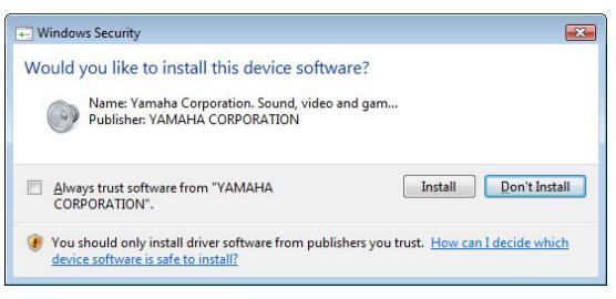
Windows Vista / Windows 7
9 When a message appears indicating that the driver has been successfully installed, click [Finish].
On some computers, it may take a few minutes before this screen appears.
10 When a window appears prompting you to restart the computer, do so.
Restart the computer by following the on-screen directions.
ENOTE This display will not appear when using Windows XP x64/Windows Vista/Windows 7. No restart is necessary.
Basic Setup
Connecting a single DME unit directly to a computer via USB cable
This section covers the most basic configuration – that is, using a single computer to control a single DMF unit.

Preparation
Before launching DME Designer, it is critical that the DME unit is turned on and then connected to the computer using a USB cable.
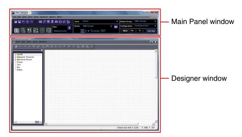
1-1 Once the DME unit has been connected, launch DME Designer.
When DME Designer is launched a new project is created and a new zone is displayed in the designer window.
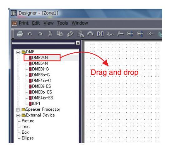
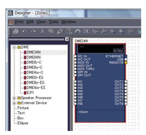
1-2 Place the desired DME unit in the designer window.
Double-click a connected DME unit shown in the list on the left side of the display (in this case a DME24N), or select a DME unit and drag-and-drop it into the designer window.
In response to this action, the Device Group and Sampling Frequency Settings window will be displayed. Click the [OK] button to proceed.
Group settings are not necessary when only one DME unit is connected. The sampling rate can be changed later on.
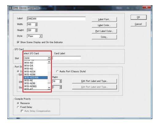
2 Mini-YGDAI Card Settings (DME64N/24N only)
The following settings are used only when one or more Mini-YGDAI cards are installed in a DME24N or DME64N. If this is not the case, proceed to Step (3. Component Layout and Connection) below.
2-1 With the Mini-YGDAI card already inserted into the DME unit, right-click on the corresponding DME icon and select [Properties...] from the bottom of the menu displayed.
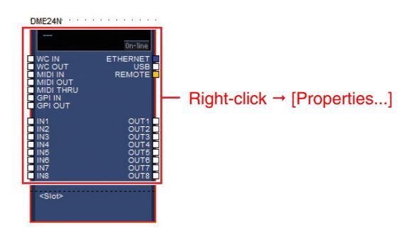
2-2 In the DME Device Properties window that is displayed, select the currently-inserted expansion card as shown below and click the [OK] button.
3 Component Layout and Connection
3-1 Double-click the icon for your DME unit to display the Configuration window.
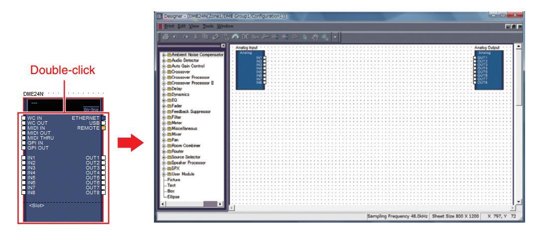
3-2 Drag and drop the components that you require into the configuration area from the list on the left-hand side.
| Dynamics Dynamics EQ Dynamics PEQ Dynamics PEQ Dynamics EQ Dynamics Dynamics EQ Dynamics Dynamics EQ Dynamics | Analog input Analog IN1 IN2 IN3 IN4 IN5 IN6 IN6 IN7 | • • |
|---|---|---|
| Drag and drop |
3-3 To connect components, click the required input or output port and drag the end of the connecting wire to the required destination.
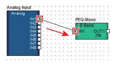
DNOTE Components can also be freely dragged around the configuration area using the mouse.
To remove a component or an incorrectly connected wire, click the component or wire, confirm that it turns red, and then press the [Delete] button on the computer keyboard.
When all necessary components have been arranged and connected in the same way, as shown in the example below, next, create a scene and transmit the setup data to the DME unit.
| nalog Input | • | • • | • | F | PE ( | Q-1 | Мо | no | r | • | • | f | a | de | r: | · | • | • | • | • | • | • | De | ela | y- | Sh | от | t: | • | • | • | • | • | Ά | nalog Output | ||||
|---|---|---|---|---|---|---|---|---|---|---|---|---|---|---|---|---|---|---|---|---|---|---|---|---|---|---|---|---|---|---|---|---|---|---|---|---|---|---|---|
| Analog | 6 | βB | ar | ١d | 1 0 | ha | anr | nei | 1 | Οι | ıtp | ut | Analog | ||||||||||||||||||||||||||
| IN1 | _ | £ | IN | 11 | 4 | DU | T | 1 0 | _ | _ | £ | ] II | ٧1 | ( | DU | T | Ē | - | - | IN' | 1 | 0 | UΤ | 1) | Þ | _ | _ | - | OUT1 | ||||||||||
| IN2 | • • | 29 | 6 | 19 | 6 | • | 1 | % | • | • | · [ | OUT2 | |||||||||||||||||||||||||||
| IN3 | • | • | _ | ٠ | · | · | · [ | OUT3 | |||||||||||||||||||||||||||||||
| IN4 | • • | • | ٠ | • | • | • | • | • | • | ٠ | • | • | • | • | • | • | • | ٠ | • | • | · [ | OUT4 | |||||||||||||||||
| IN5 | · [ | п | OUT5 | ||||||||||||||||||||||||||||||||||||
| IN6 | ٠Ī | ٦ | OUT6 | ||||||||||||||||||||||||||||||||||||
| IN7 | ٠Ī | ٦ | OUT7 | ||||||||||||||||||||||||||||||||||||
| IN8 | • | ٠Ì | 1 | OUT8 | |||||||||||||||||||||||||||||||||||
| Ľ. | П | ||||||||||||||||||||||||||||||||||||||
4 Creating scenes
In order to transmit all data created thus far to a DME unit, it is necessary to store at least one scene. The scene store procedure is outlined below.
4-1 Click the [Scene Manager] button from the Main Panel window to display the "Scene Manager" dialog box.
| x | ||
|---|---|---|
| case | 2.daf | |
| Zone Zone1 | Device Group DME Group1 | ▼ |
| Scene DME Group1 | Configuration Configuration1 | ▼ |
| [][] { ▼ Scene 001 | Mute Rx ||| Tx ||| On-lin | ne |
4-2 Click the [Store] button in the "Scene Manager" dialog box.
| Qut | 0; | py B | iste jn | sert Cjea | ¥. | Recall S | ţfe | ||
|---|---|---|---|---|---|---|---|---|---|
| DME Group | 1 | ŀ | |||||||
| Scene No. | Name | Configuration | Edit Security | Recall Security | Fade | Fade Mode | Fade Time | Protect | Ŀ |
| 301 | [No Data] | - | - | - | - | - | - | - | 12 |
| 302 | [No Data] | - | - | - | - | - | - | - | |
| 303 | [No Data] | - | - | - | - | - | - | ||
| 004 | [No Data] | - | - | - | - | - | - | - | |
| 105 | [No Data] | - | - | - | - | - | - | - | |
| 306 | [No Data] | - | - | - | - | - | - | - | |
| 307 | [No Data] | - | - | - | - | - | - | - | |
| 008 | [No Data] | - | - | - | - | - | - | - | |
| 009 | [No Data] | - | - |
4-3 Click the [OK] button.
| Enter scene name. | |
|---|---|
| 0.001 | |
| Scene UUI | |
| ОК | Cancel |
5 Going On-Line
When synchronization with the DME unit has been achieved and the connection is online, the DME Designer settings are written to the DME unit.
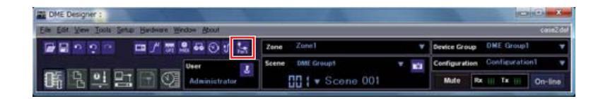
5-1 Click the [Communication Port] button from the Main Panel window to display the "Communication Port" dialog box.
5-2 When the "Communication Port" dialog box is displayed, ensure that the Tx, Rx, and Device Group settings are as shown below. When "No Assign" is selected for Port 1, click the item and select an appropriate option from the list that appears.
ENCTE If the appropriate option list does not appear even though the USB-MIDI driver is installed, check that the DME unit is properly connected to the computer.
| 1 | Yamaha DME24N-1 | Yamaha DME24N-1 | DME Group1 |
|---|---|---|---|
| 2 | No Assign | No Assign | No Assign |
5-3 Click the [On-line] button from the Main Panel window.
| case2.daf | ||
|---|---|---|
| Zone Zone1 🔻 | Device Group DME Group1 | |
| ٦ | Scene DME Group1 V | Configuration Configuration1 |
| ∏ { ▼ Scene 001 | Mute Rx ||| Tx ||| On-line |
5-4 When the Synchronization window is displayed, the text "Select IP Address" will be displayed in red. Click this message and select the required IP address from the drop-down menu.
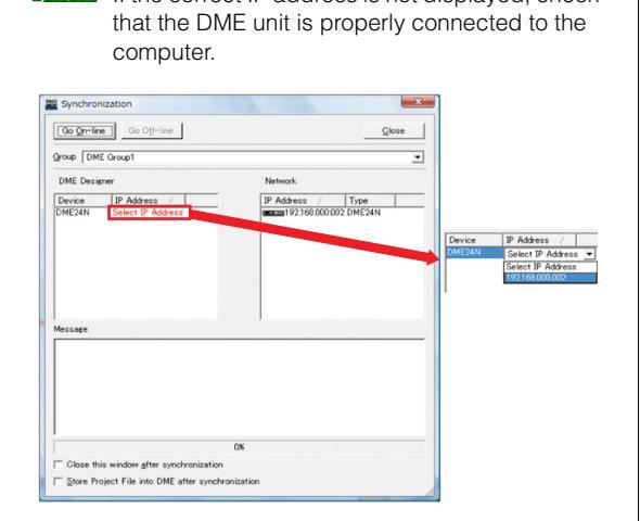
DNOTE If the correct IP address is not displayed check

| Go On-lin | e Go Off-line |
|---|---|
| roup DMB | E Group1 |
| DME Desig | mor |
| DME Desig | ner |
|
DME Desig
Device |
ner
IP Address 🕢 |
5-6 When the Sync Direction window is displayed, ensure that [DME Designer -> Device] is selected, and then click the [OK] button.
| DME Design | er -> Device | |
|---|---|---|
| DME Design | er <- Device | |
| - | OK | Gancel |
5-7 In response to the prompt, "Synchronizing will cause audio to mute. Is this OK?", click the [Yes] button.
5-8 When writing has been completed, the message, "Saving the Designer file after synchronization will enhance the speed of the next synchronization. Do you want to save now?" will be displayed. If you want to save the file, click the [Yes] button.
5-9 After returning to the Synchronization window, click the [Close] button.
When synchronization processing has finished and the connection is online, the [On-line] button in the main panel window will light.
| Device Group | DM | E G | roup | ||
|---|---|---|---|---|---|
| Configurat | ion | Cor | nfigu | iratio | on 1 |
| Mute | Rx | Ш | Тх | Ш | On-line |
To go offline, click the [On-line] button to turn it off.NOTE
ENOTE If the IP address of the DME device is changed after the device has been synchronized with DME Designer, it will be necessary to re-transfer the configuration data by performing a "Full Resync" operation. Refer to the "Online" section in Chapter 2 of
the DME Designer Owner's Manual for details about the "Full Resync" operation.
6 Checking sound output
In the case of DME24N, DME8i-C, DME4io-C, DME-8i-ES or DME4io-ES units, appropriate HA control settings must be made prior to checking the system's sound output.
6-1 Right-click the [Analog Input] component and select [Open HA Editor] from the drop-down menu.
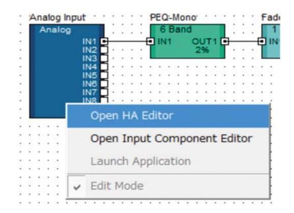
An "Analog" dialog box that allows head amp settings will appear.
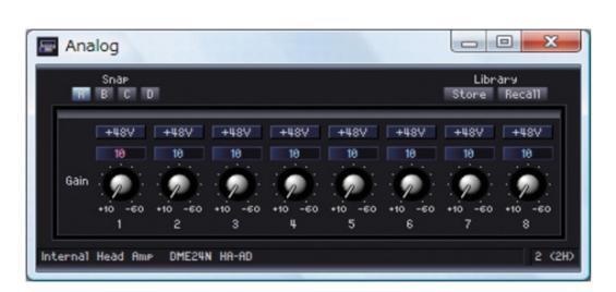
By default, the gain is set to +10 dBu (i.e., the lowest possible gain).
6-2 Adjust the sensitivity to the correct level for the connected audio equipment.
DINCE The level displayed by [Gain] is the sensitivity level to be matched. As the sensitivity of most professional audio equipment (using XLR connectors) is +4 dBu, the level shown by [Gain] should be set to "4" in such a case. When using input from microphones or other similar sources, turn the dial clockwise to adjust the input volume to a suitable level. Specifically, it is recommended that the level shown by the input meter be peaking at around -18 dB.
Advanced Setup
Connecting multiple DME units to a computer via Ethernet cables
In the following two cases, a USB cable should not be used to connect your computer and DME units for actual operation; instead, you should make the necessary connections via Ethernet cables.
- Two or more DME units are to be controlled in a single device group (using a Network switch).
- When the distance between the DME unit and computer is too great for a USB connection.
- DIVIT If a company or office network is to be used for this purpose, it will be necessary to switch back and forth between the DME network and the regular network. In such a case, we recommend connection via USB or the use of a commercially-available Ethernet/USB interface.
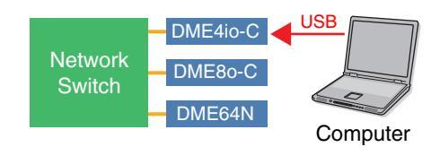
Setting example
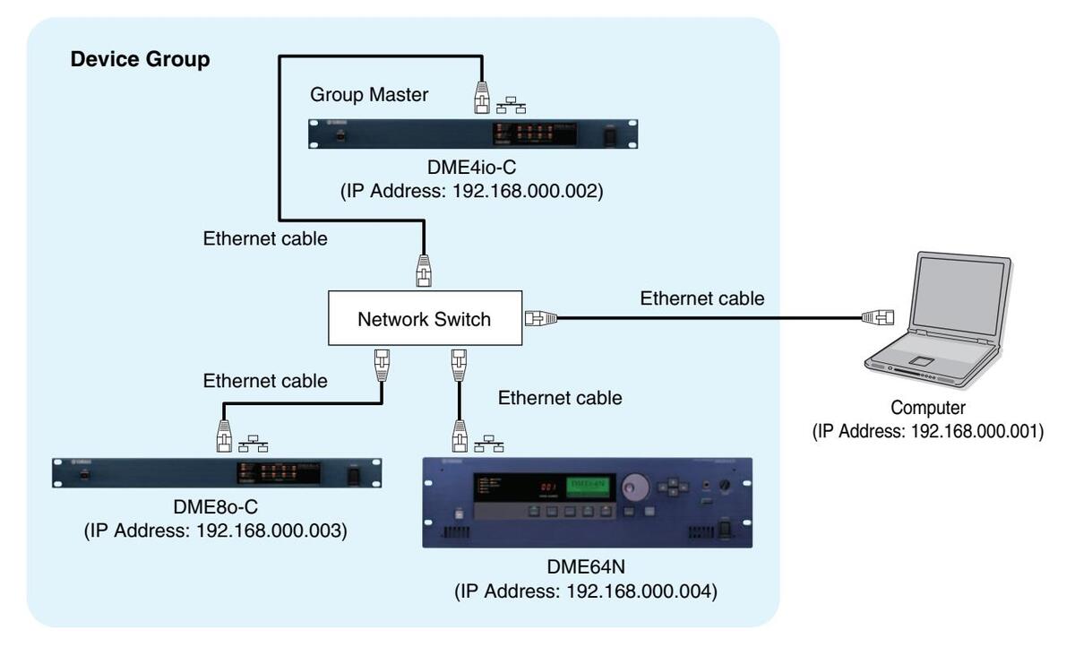
- When multiple DME units are being used, the DME units are controlled in "device groups." Since all DME units in a device group are controlled via the group's master DME unit, one DME unit in each group must be designated as the group master.
- The device group master DME unit can be connected to the computer via a USB cable. Slave DME units can be connected to the group master via USB cables.
- ENOTE Use a network switch that is capable of 100Base-TX operation.
- The maximum length of cables that can be used to connect DME units to a network switch is 100 meters. Proper operation at this length, however, will depend on the quality of the network switch and cables used, and cannot be guaranteed.
- ENOTE Use CAT5 STP (shielded twisted pair) type cable to maximize resistance to electromagnetic interference.
- If you are using multiple DME series units, set Link Mode on each unit to the same setting. Yamaha recommends that you select 100Base-TX for the Link Mode setting.
DME Network Settings
Before making the DME network connections, set the device group and IP address for each DME unit from DME Designer via a USB connection.
By default, all DME units are assigned the IP address 192.168.000.002.
Please ensure that the USB-MIDI driver has been installed before proceeding.
- The same driver can be used for multiple DME units of the same type (DME64N, DME24N, DME Satellite). A common USB driver can be used for multiple DME Satellite units.
- If using a DME64N or DME24N, setting can be performed directly via the front display (page 21). ICP1 settings can be made via the unit's control panel. Refer to "ICP1 settings and operation" of the DME Designer V3.8 Owner's Manual.
- 1 Connect the computer to the DME unit via a USB cable, then turn the DME unit power ON.
2 Click the [Communication Port] button from the Main Panel window to display the "Communication Port" dialog box.
3 Select either "YAMAHA USB OUT 0-1" or "Yamaha DME NETWORK-1" for the [Tx] (transmit) field, and "YAMAHA USB IN 0-1" or "Yamaha DME NETWORK-1" for the [Rx] (receive) field, and click the [OK] button.

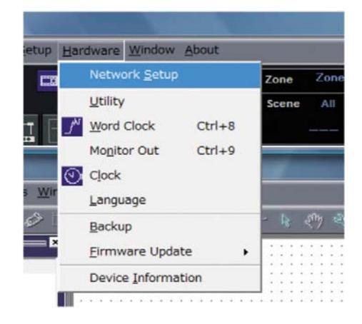
4 Click the [Network Setup] from the [Hardware] menu on the Main Panel window to display the "Network Setup" dialog box.
5 Make sure that the "Network Setup" dialog box settings are made as shown below, the click the [OK] button.
| Master/Slave | Master |
|---|---|
| IP Address | 192.168.0.2 |
| Master ID | _ |
| Link Mode | 100Base-TX |
Group master settings (DME4io-C in the example).
| MIDI Port List (Tx/Rx) | Network Setup | |
|---|---|---|
| ramana ume ne rivoros-17 ramana ume ne rivoros | Master/Slave | |
| IP Address | 192 . 168 . 0 . 2 | |
| Master ID | ||
| Link Mode | C 10Base-T C 100Base-TX | |
| MAC Address | 00 A0 DE 25 21 00 | |
CINOTE The default settings can be used for the group master.
6 Use the same procedure to set the slave (DME8o-C and DME64N in the example) settings and IP address.
| DME8o-C | DME64N | |
|---|---|---|
| Master/Slave | Sla | ave |
| IP Address | 192.168.0.3 | 192.168.0.4 |
| Master ID | 192.168.0.2 | |
| Link Mode | 100Ba | ase-TX |
ENOTE The subnet mask is fixed at "255.255.255.0".
The host address can be set from 2 to 253 for the Master device, and from 3 to 253 for Slaves.
- Always use a private address (192.168.0.2. through 192.168.255.253) unless it is absolutely necessary to use a global address. Consult with the network administrator if it is necessary to use a global address.
- Although an error will be displayed on DME units at this time, it can be ignored. (This message is output due to group settings not yet having been made.)
Slave settings (DME8o-C in the example).
Slave settings (DME64N in the example).
| WORK Setup | ||
|---|---|---|
| Master/Slave | ← Master | Slave |
| P Address | 192 . 168 | . 0.3 |
| Master ID | 192 . 168 | 2 |
| ink Mode | C 10Base-T |
| etwork Setup | ||
|---|---|---|
| Master/Slave | C Master | ( Slave |
| TP Address | ||
| II HUUICSS | | 192 . | 168 | • • |
| Master ID | 192 168 | . 0. 2 |
| Link Mode | C 10Base-T |
If the IP address of the DME device is changed after the device has been synchronized with DME Designer, it will be necessary to re-transfer the configuration data by performing a "Full Resync" operation. Refer to the "Online" section in Chapter 2 of the DME Designer Owner's Manual for details about the "Full Resync" operation.
Computer Network Settings
The computer's IP address and TCP/IP filtering must be set up to allow network communication with the DME device(s).
The "Local Area Connection Status" dialog box will be displayed
DNOTE If the "Local Area Connection properties" dialog box appears, skip ahead to step 5.

5 Select [Internet Protocol (TCP/IP)] on the [General] tab, then click [Properties].
The "Internet Protocol (TCP/IP) Properties" dialog box will be displayed.
6 Click [Detailed Settings], then in the "TCP/IP Detailed Settings" dialog box click [Properties] in the [Options] tab.
The "TCP/IP Filtering" dialog will be displayed.
7 Select "Permit All" for TCP Ports, then click [OK].
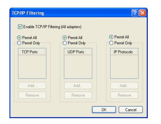
The display returns to the "Advanced TCP/IP Settings" dialog. Click [OK] to return to the "Internet Protocol (TCP/IP) Properties" dialog.
Consult the network administrator if settings need to be changed.
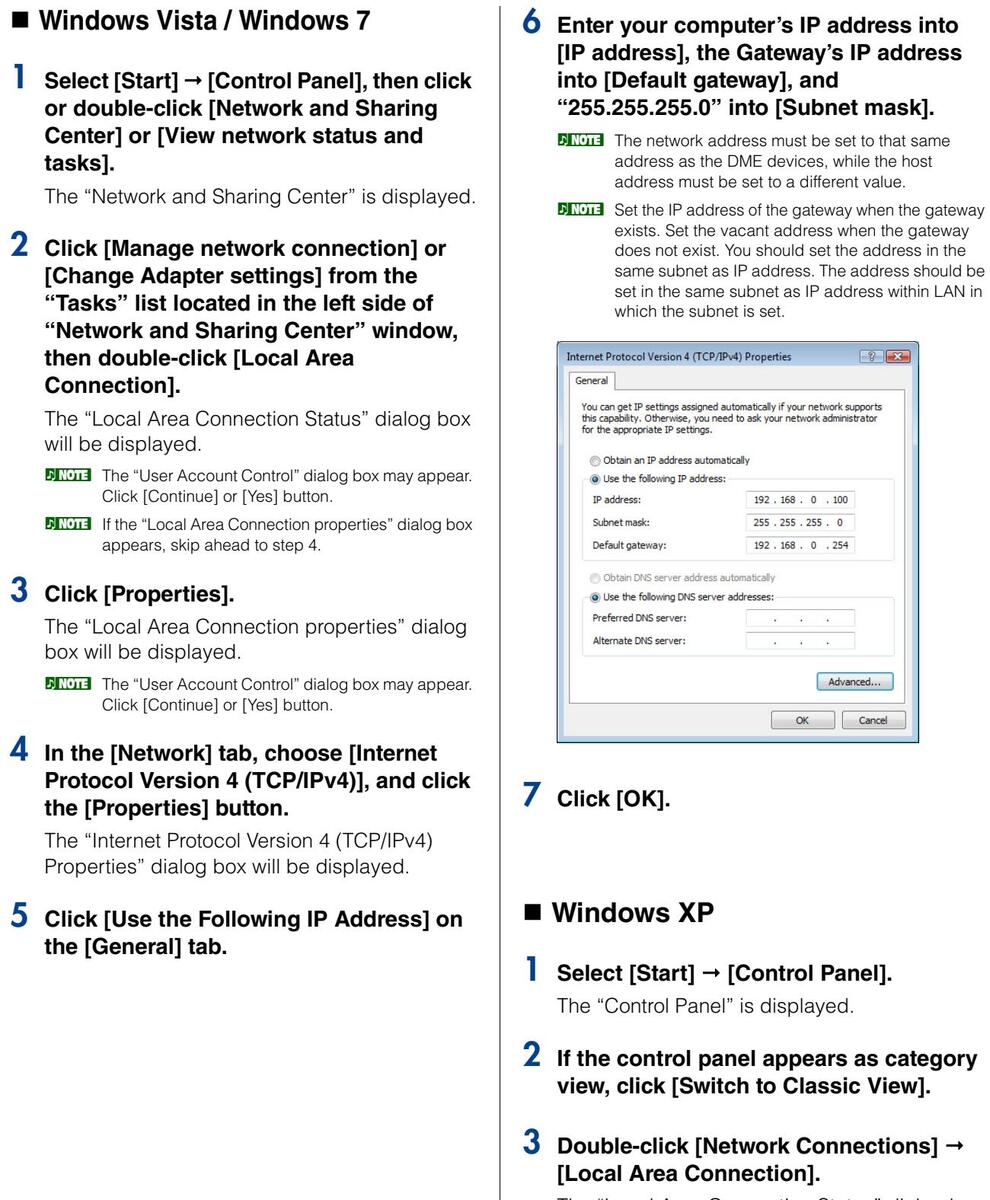
8 Click [Use the Following IP Address].
Enter your computer's IP address into [IP address], the Gateway's IP address into [Default gateway], and "255.255.255.0" into [Subnet mask].
The network address must be set to that same address as the DME devices, while the host address must be set to a different value.
| iternet Protocol (TCP/IP) P | roperties ? |
|---|---|
| General | |
|
You can get IP settings assigned
this capability. Otherwise, you ne- the appropriate IP settings. |
automatically if your network supports
ed to ask your network administrator for |
| 🔘 Obtain an IP address autom | atically |
| • Use the following IP address | s: |
| IP address: | 192.168.0.100 |
| Subnet mask: | 255 . 0 |
| Default gateway: | 192.168.0.254 |
| Obtain DNS server address | automatically |
|
er addresses: |
| Preferred DNS server: | |
| Alternate DNS server: | |
| Advanced | |
| OK Cancel |
10 Click [OK].
DIVIT If the computer is being used in an office, for example, and already has an assigned IP address, either the current settings will have to be changed or the computer will have to be connected to the DME unit via a USB cable.
DME Network Connections
When the necessary settings have been made, connect the DME units and computer via a switching hub using Ethernet cables, as shown in the example on page 13.
ENOTE Set the gateway IP host address to 254.
Setting the DME-N Network Driver
In order for the computer to recognize the DME device(s), it is necessary to register the IP address and device name of the DME device that is the Device Group Master.
ENOTE Refer to page 23 for details on DME-N Network Driver setup
Select [Start] → [Control Panel].
The "Control Panel" will appear.
2 If the control panel appears as category view, switch the view as follows:
For Windows XP
Click [Switch to Classic View] in the upper left of the control panel.
For Windows Vista
Click [Classic View] in the upper left of the control panel.
For Windows 7
Click [View by : Category] in the upper right of the control panel, and select "Large icons" or "Small icons".
3 Double-click the [DME-N Network Driver] icon.
The "DME-N Network Driver" dialog box will appear.

4 Click the [Advanced Settings] button to open the "Advanced Settings" dialog box.
DME devices connected to the network can be automatically detected via this dialog box.
| Detect | from | 192 | 168 0 | . 2 |
|---|---|---|---|---|
| Detect | to | 192 | . 168 . 0 | . 10 |
| urreni | tly searching | Star | Abort | |
| Add | Device IP Ad | ldress | Device Name | Device MAC Address |
| Add t | o Device I | .ist C | lancel | |
| Import celt | up from fil | e| E | coort setup to file |
5 Enter the IP address range over which you would like to automatically detect connected DME devices in the [Detect from] and [Detect to] fields, and click [Start].
Automatic DME detection will begin.
- In this example the IP address of the first device is 192.168.0.2, the IP address of the second device is 196.168.0.3, and the IP address of the third device is 192.168.0.4. In this case it is necessary to set the last [Detect from] digit to 2 or lower, and the last [Detect to] digit to 4 or higher. Note that setting an excessively large detection range can result in long detection times.
- 6 When automatic DME device detection has finished, check the [Add] box of the DME device that is to function as the Device Group Master, and click [Add to Device List].
The "Advanced Settings" dialog box will close and return to the "DME-N Network Driver" dialog box.
| Advanc | ed Settings | |||
|---|---|---|---|---|
|
- Auto I
Detect Detect |
betect
from 192 to 192 tly searching Start |
. 168 . 0
. 168 . 0 |
. 2
. 10 |
|
|
Device IP Address
192, 168, 0, 2 192, 168, 0, 4 192, 168, 0, 5 |
Device Name |
Device MAC Address
00 A0 DE 25 15 A8 00 A0 DE 25 15 B0 00 A0 DE 25 15 B3 |
||
| Add to Device I | e Ex | port setup to file |
DINOTE If the IP address was not automatically detected, register the DME device manually (page 23).
7 Select the DME unit that is to function as the Device Group Master from the Target Device List, enter the Device Name and Device Port No., and click the [Apply] button.
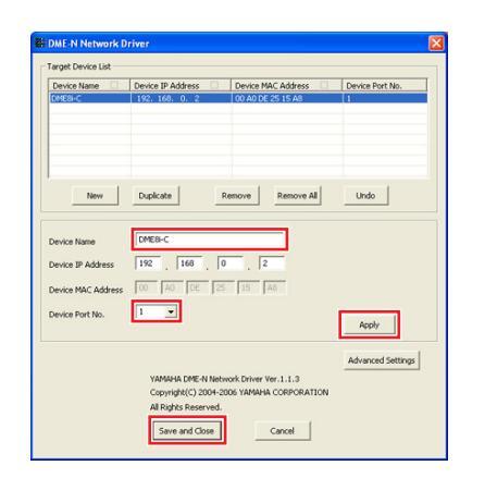
Device Name
Displayed as the port name in DME Designer.
Device Port No. (MIDI port number)
Set to "1." "2" is also available for DME64N/24N devices.
8 Click the [Save and Close] button to close the dialog box.
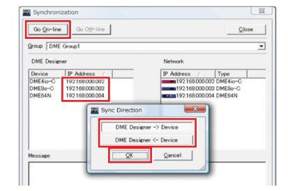
Going On-Line
- Place and connect the required components as described in the basic setup procedure (page 7) beginning from step 1-1.
- 2 Click the [On-line] button from the Main Panel window.

3 Click "Select IP Address", ensure that the IP addresses for all devices are displayed collectly, and then click the [Go On-Line] button.
4 When the Sync Direction window is displayed, ensure that [DME Designer -> Device] is selected, and then click the [OK] button.
Check sound output as described in the Basic Setup section (page 12).
In-depth Information on DME Units
Connecting to External Controllers
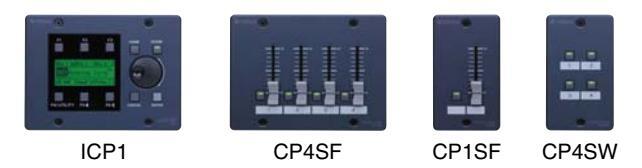
ICP1, CP4SF, CP1SF, and CP4SW controllers are available as optional extras for remote external control of the DME units. For details regarding installation of a control panel and connection to the DME unit, please refer to the owner's manual that came with the control panel.
Connection via Ethernet
Intelligent Control Panel ICP1
Connection via General Purpose Interface (GPI)
Control Panel CP4SF, CP1SF, or CP4SW

Check Input Signals via the GPI Page
Signals received at the GPI IN terminals can be monitored in real time via the Utility screen GPI page on the DME64N/24N control panel display, or via the DME Designer Utility dialog box GPI monitor. If the DME unit is not responding properly even though the appropriate signals are being received at the GPI IN terminals, there may be a problem with the DME settings. If there is no problem with the DME settings there may be a problem with the DME unit itself.
Maximum length of GPI cables
CPEV cables with a core diameter of 0.65 mm or more can be used over distances of up to 100 m.
Setting up DME64N/24N Networks via Panel Operations
Device group and IP address settings for DME64N and DME24N units can be made directly via their front panels as follows.
- 1 Turn on the DME64N/24N.
- 2 Press the [HOME] button to display the main screen.
3 Press and hold the [UTILITY] button for at least 2 seconds to display the Utility screen.
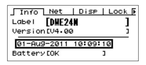
4 Press the [UTILITY] button several times until the Net page appears.
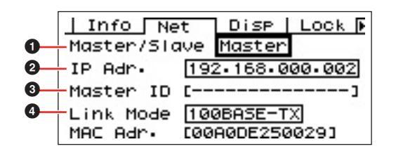
5 Use the [▲] and [▼] buttons to move the cursor to the parameters listed below and press the [ENTER] button.
The corresponding editing dialog will appear. Set each of the following parameters as described and press the [ENTER] button each time to confirm and enter the settings.
Master/Slave
This parameter sets device-group master or slave status.
One DME unit must be assigned as the master in each device group. All other DME units in the group should be set to slave.
2 IP Address
Set the IP addresses of the DME devices. All DME devices in the same Device Group must be set to the same network address.
- When only one DME unit (Master) is used, the IP address should be set to "192.168.0.2".
- ENOTE The subnet mask is fixed at "255.255.255.0".
- The host address can be set from 2 to 253 for the Master device, and from 3 to 253 for Slaves.
Always use a private address (192.168.0.2. through 192.168.255.253) unless it is absolutely necessary to use a global address. Consult with the network administrator if it is necessary to use a global address.

Network address Host address
Master ID
When a device is assigned as a Slave in Master/ Slave (①) above, this sets the host address for the Master device in that group. This parameter cannot be set for the Master device.
4 Link Mode
Ensure that "100Base-TX" is selected for this parameter.
6 Press the [HOME] button to return and save your changes.
Related web site on DME series and peripherals
- The latest information about DME units is available from the Yamaha Pro Audio website: <a href="http://www.yamahaproaudio.com">http://www.yamahaproaudio.com</a>
- The latest version of the DME unit firmware and DME Designer can be downloaded from the Yamaha ProAudio website: <a href="http://www.yamahaproaudio.com/downloads/firm_soft/index.html">http://www.yamahaproaudio.com/downloads/firm_soft/index.html</a>
- Library data for DME series Speaker Processor Components and DME remote control protocol specifications is available from the "Downloads" page of the Yamaha Pro Audio website: <a href="http://www.yamahaproaudio.com/downloads/documents/index.html">http://www.yamahaproaudio.com/downloads/documents/index.html</a>
- For information on touch panel controllers by other manufacturers, visit: AMX's web site: http://www.amx.com/ CRESTRON's web site: http://www.crestron.com/
DME-N Network Driver Setup Details
"DME-N Network Driver" dialog box
Select [Start] → [Control Panel] → [DME-N Network Driver] to open the "DME-N Network Driver" dialog box. The parameters in this dialog box set up the device information of the DME on the network.
| [ | [a., | ||
|---|---|---|---|
| Device Name | Device IP Address | Device MAC Address | Device Port No. |
| DME8i-C | 192. 168. 0. 2 | 00 A0 DE 25 15 A8 | 1 |
|
DME04N
DME24N |
192, 168, 0, 4 | 00 A0 DE 25 15 B0 | 1 |
| New | Duplicate | Remove All | Undo |
| evice Name | DME8i-C | ||
| Device IP Address | 192 . 168 . 0 | 2 | |
|
Device IP Address
Device MAC Address |
192 168 0 |
2
15 A8 |
|
|
Device IP Address
Device MAC Address Device Port No. |
192 . 168 . 0
00 A0 DE 25 |
2
15 A8 |
Apply |
|
Device IP Address
Device MAC Address Device Port No. |
192 168 0
00 A0 DE 25 |
2
15 A8 |
Apply
Advanced Setting |
|
Device IP Address
Device MAC Address Device Port No. |
192 168 0 |
0 2
15 A8 work Driver Ver.1.1.3 |
Apply Advanced Setting |
|
Device IP Address
Device MAC Address Device Port No. |
192 168 0
00 A0 DE 25 1 VAMAHA DME-N Net Copyright(C) 2004-2 |
VICE VERTICAL CORPORATION |
Apply
Advanced Setting |
1 Target Device List
The name. IP address. MAC address, and MIDI port number of all devices registered to communicate with the DME-N Network Driver are shown in this list Click the title bars to sort accordingly When a device is selected in the list, information related to that device will be viewed and edited in the Device information (2) area below the list.
Device Name Device IP Address Device MAC Address Device Port No
These fields display the name. IP address MAC address, and MIDI port number of the corresponding devices. Refer to the Device information ( 2 ) area for more details
[New] Button
Click this button to add a new device to the list. Edit the device's parameters as required via the fields in the Device information (2) area below the list the click the [Apply] button to add the specified device
[Duplicate] Button
This button adds a device to the list by copying the data from the currently selected device. Edit the new device's parameters as required via the fields in the Device information (2) area below the list, then click the [Apply] button to add the specified device.
[Remove] Button
Deletes the selected device from the list. If the removed device is not the lowest device in the list all devices below the removed device will be shifted upward to maintain the continuity of the list.
[Remove ALL] Button
Deletes all devices from the list
[Undo] Button
This button provides a one-step undo function that allows you to undo a single operation and revert to the previous state. The [Undo] button will be graved out and inaccessible immediately after an undo operation or after the control panel is launched
2 Device information
When a device that is registered for communication with the DME-N Network Driver is selected in the Target Device List, the communication parameters for that device can be viewed and edited in the device information fields
[Device Name]
This is the name of the device selected in the Target Device List. The initial default settings are "UNIT1" through "UNIT256", but the name can be edited as required in this field
[Device IP Address]
The IP address of the device selected in the Target Device List can be set via these fields. Refer to page 16 for details on checking and setting its IP
[Device MAC Address]
The MAC (Media Access Control) address of the device selected in the Target Device List can be set via these fields. The MAC address of each device is permanently assigned when the device is manufactured and cannot be changed. The MAC address parameter is included to prevent data from being sent to the wrong device if the IP address in inadvertently set incorrectly.

ENOTE The MAC address must be set properly or communication with the device will not be possible
ENOTE The Device MAC Address setting cannot be changed for the device connected to the network.
ENOTE The IP address must be set properly or communication with the device will not be possible
[Device Port No.]
The MIDI port number of the device selected in the Target Device List can be set via this menu. The MIDI port number also functions as device ID number. It can be set to "1" or "2" for DME64N/24N units. It should be set to "1" for DME Satellite units.
The MIDI port number must be set properly or communication with the device will not be possible.
[Apply] Button
Click the [Apply] button after editing the Device Name, Device IP Address, Device MAC Address, or Device Port No. parameters to actually apply the changes. Also, devices added to the Target Device List (1) by pressing the [New] or [Duplicate] buttons will only actually be registered for communication with the DME-N Network Driver when the [Apply] button is pressed.
[Advanced Settings] Button
Opens the "Advanced Settings" window. This window provides access to advanced settings. For details refer to the "Advanced Settings" dialog box in the next section.
"Advanced Settings" dialog box
Click [Advanced Settings] in the DME-N Network Driver dialog box to display the Advanced Settings dialog box. The parameters presented in this dialog box are used to setup automatic detection by the DME-N Network Driver; furthermore, setup files can also be imported and exported here.
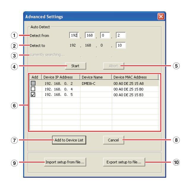
Auto Detect
Allows automatic detection of connected devices that can communicate with the DME-N Network Driver. A maximum of 254 addresses (***.***.1 through ***.***.254) can be detected.
Only MAC addresses of devices on the same subnet as the computer can be detected. Before searching for MAC addresses make sure that the computer is connected to the subnet to be searched, and that an appropriate IP address is assigned.
1 Detect from
Specifies the start IP address for automatic detection.
2 Detect to
Specifies the end IP address for automatic detection.
③ currently searching
Displays the IP address being checked during automatic detection. No display when automatic detection is not in progress.
(4) [Start] Button
Initiates automatic detection, and causes the detected device list (((i)) to be updated accordingly. This button is grayed out and is not accessible during automatic detection.
(5) [Abort] Button
Aborts automatic detection. This button is grayed out when automatic detection is not in progress.
6 Detected Device List
This list shows all detected devices that are capable of communication with the DME-N Network Driver. No devices will be displayed initially.
[Add]
Checked devices will be added to the Target Device List when the [Add to Device List] button (below) is clicked. Devices that are already registered cannot be checked.
[Device IP Address]
The IP address of the corresponding detected device.
[Device Name]
If a name has been registered for the detected device it will be displayed here, otherwise no name will be displayed.
Device MAC Address
The MAC address of the corresponding detected device.
⑦ [Add to Device List] Button
Devices with checked [Add] checkboxes will be added to the Target Device List when this button is clicked.
8 [Cancel] Button
Closes the dialog box without making any changes.
(9) [Import Setup from File] Button
When working in a different environment it is possible to load a previously saved setup file. Click to open the "Open" dialog. Select a setup file and then click the [Open] button to import the corresponding settings.
10 [Export Setup to File] Button
It is possible to save the setup data to a file that can then be reloaded when working in a different environment. Click to open the "Save As" dialog. Enter a file name and click the [Save] button to save the setup file.
Troubleshooting & Tips
| Problem | Possible cause | Corrective action |
|---|---|---|
|
The DME unit does not operate
correctly in response to control from DME Designer via USB. |
DME Designer was launched before
connecting the USB cable and turning on the DME unit. |
Ensure that the USB cable is connected and the DME unit is turned on before launching DME Designer. |
|
The USB-MIDI Driver Thru ON/OFF
parameter is not set to "OFF". |
The USB-MIDI Driver Thru ON/OFF parameter is not set to "OFF". | |
|
The same USB ports have been
selected for DME Designer and other MIDI applications. |
Change port settings so that DME Designer and the other MIDI applications use different ports. | |
| The number of registered MIDI devices exceeds the Windows limit. | The Windows operating system allows a maximum of 10 MIDI device drivers to be installed and registered. In certain cases, connecting a device to a different USB port can lead to it being recognized as a different device, thereby "artificially" exceeding the limit. If MIDI does not work properly, therefore, try uninstalling (page 28) and then reinstalling the USB-MIDI driver. | |
| Your USB-MIDI driver is not the most up-to-date version supported by DME. | Download and install the most up-to-date USB-MIDI driver from the Yamaha website ( http://www.yamahaproaudio.com/ ) | |
| The MIDI port setting is "USB-1" or "USB-2". |
If the Port setting in the DME64N/24N Utility screen MIDI page is
"USB-1" or "USB-2" (in the case of a DME Satellite this can be confirmed in the DME Designer Utility dialog box MIDI tab), MIDI data will be transferred via the USB connection, possibly interrupting USB communication with DME Designer. Avoid this type of setup. |
|
| A compile error occurs during synchronization. | DSP total resource consumption has exceeded the upper limit. |
Delete unneeded components. In addition, it may be possible to
ensure that compilation will be completed normally even when total DSP resource consumption increases by replacing some components with others using fewer resources or by dividing the processing load between such components. The Analyze function provides a handy way to check whether compilation will be successfully completed prior to synchronization. |
|
Wiring between components is
connected from multiple output ports to a single input port. |
Change the wiring configuration so that each output is connected
to a single input port. If necessary, a matrix mixer or similar component can be used to combine multiple outputs into one signal. |
|
| A component or wiring cannot | DME Designer is online. | Go offline by clicking [Go Off-line] in the Synchronization window. |
| be added. |
The Designer Window is not in Edit
Mode. |
Place a checkmark next to [Edit] on the [Tool] menu. |
| The current user is restricted from editing. |
Logoff and then logon again as a new user or as the
Administrator. To allow editing by the user, turn the [Edit] option in the "Security" window ON. |
|
| No user modules appear in the list. |
The contents folder ([File] menu →
[Preference] → [ContentsFolder]) has been changed, or the "UserModule" folder has been moved. |
Ensure that the user module files (.umf) are in the "UserModule" folder and "ContentsFolder" folder's settings. |
|
Configurations cannot be
switched in the Navigator window. |
While online, it is not possible to switch
to a configuration that does not match the current scene. |
Switch to a scene corresponding to the required configuration. |
|
A User Module window does not
open when the user module is double-clicked. |
The user module in question has
been saved with [Open User Module Design Window] selected. |
Open the save dialog, select [Open User Module Editor], and resave the user module. |
|
An editor is not displayed when
a slot-in component is right- clicked and [Open] is selected from its context menu. |
An editor is not provided for the corresponding slot-in component. | _ |
| Problem | Possible cause | Corrective action |
|---|---|---|
|
The message "Reset Config"
is displayed for a long time in the message area of the Synchronization window. |
Processing may take time when many scenes have been stored. | _ |
|
The monitor output cannot be
set. (Applies to the DME64N and DME24N only.) |
Output ports that are already in use
(i.e. wired) cannot be selected as monitor outputs. |
Select an unused output port. |
| Caution | |
|---|---|
| USB ports and driver installation |
On computers featuring multiple USB ports, drivers are installed individually for each port. After installation, therefore, if connection is made via a port other than that originally used, it will be necessary to install the driver once again. To avoid this, either decide a dedicated port for DME connection in advance or install the driver on all of your computer's ports.
It is also important to note that USB drivers differ depending on the model of DME used. Although the same driver can be used for multiple DME units of the same model, different models – such as the DME64N and DME24N – require different USB drivers. (The USB drivers themselves are identical, but the INF files used upon installation differ.) |
| Avoid USB hubs | Connection should be made directly to one of your computer's built-in USB ports. Your computer may not recognize the DME unit if connected via a USB hub. |
| Over-the-counter security software | If antivirus, anti-spyware, or any other type of Internet security application is installed on your computer, its firewall may block the DME-N Network Driver, making connection and remote operation of the DME unit impossible. Care should also be taken with regard to compatibility with peer-to-peer applications and other communication software remaining constantly on in the background. |
| PC power-saving options | With laptops, certain power saving options can result in network communication being automatically turned off, which would lead to disconnection of the DME unit if online at the time. Should you become aware of this type of behavior, please check your power saving options. |
| Wireless network | Over-the-counter wireless network access points can be used to establish connections with laptops featuring wireless functionality. A good understanding of network will be required in order to do so, and the access point's user manual should be referenced for setting-related details. |
| Word-clock settings |
When a new file is created using DME Designer, the word clock is set to "INT48k" by default. In systems where the DME unit operates as a word-clock slave, it will be necessary to change this word-clock setting before going online.
If the DME unit were to be brought online with the default setting unchanged, it would not be word-clock locked with the other units in the system, resulting in audible clicking and possibly damage to the other units. Whenever possible, it is recommended that clock settings be made using DME Designer. |
| DME initialization |
In certain cases, DME initialization can prove effective in resolving problems. In particular, this approach is useful if a DME unit freezes upon scene recall (either during startup or when connected online).
Take care to avoid selecting option 02 (Delete All Data), as this will result in the DME device's firmware also being deleted. It cannot be used the device until the firmware is reinstalled. For details regarding initialization, please refer to the Owner's Manual that came with your DME device(s). Specifically, this information can be found in the section "Initializing the DME64N/DME24N" of the DME64N/DME24N manual, or in the section "Initializing the DME Satellite" of manuals for DME satellites. |
| Using the Analyze function |
After a configuration has been created using DME Designer, we recommend that the Analyze function be used to check it. Please note that unless this function is used it will not be possible to determine whether the created configuration will be executable.
The resource meter alone does not provide an indication of whether it will be possible to go online. It is important, therefore, that the Analyze function always be used to perform a final check. Also be sure to set the sampling frequency properly before using the Analyze function. For example, even if the analysis result is OK for 48 kHz, DSP resources may not be sufficient for operation at 96 kHz. Set the sampling frequency via the [Hardware] → [Word Clock] dialog box in the main panel window. |
| Automatic backup function and going online | If the [Store Project File into DME after synchronization] option at the bottom left of the Synchronization window is ON, when going online with DME Designer version 3 or later, DME Designer will create a backup of the computer's current data (.daf) within the DME unit's memory after going online. Please note that if Wave files are being used, synchronization can take at least twice as long as usual. Furthermore, if your original project file is accidentally deleted or lost, synchronization with DME devices will no longer be possible. For safety's sake, therefore, it is advisable that a backup be made and that the [Store Project File into DME after synchronization] option from the Synchronization window or the DME File Storage function from the [File] menu be used to store a copy of this file also on the DME device(s). |
Uninstall the USB-MIDI Driver
Windows XP
- Disconnect all USB devices from the computer except for the mouse and keyboard.
- 2 Start the computer and log on to the Administrator account.
Exit from any open applications and close all open windows.
- From the [Start] menu, select ([Settings] →) [Control Panel] → [Add or Remove Programs] to display the Add or Remove Programs panel.
- 4 Click "Change or Remove Programs" located in the upper left, then select "Yamaha USB-MIDI Driver" from the list in the right panel.
- 5 Click [Remove].
A dialog box appears. Follow the instructions to remove the software.
Windows Vista / Windows 7
- Disconnect all USB devices from the computer except for the mouse and keyboard.
- 2 Start the computer and log on to the Administrator account.
Exit from any open applications and close all open windows.
- 3 From the [Start] menu, select the [Control Panel] → [Programs and Features] or [Uninstall a program] to display the "Uninstall or change a program" window.
- 4 Select "Yamaha USB-MIDI Driver" from the list.
5 Click [Uninstall].
If the "User Account Control" window appears, click [Allow] or [Continue]. A dialog box appears. Follow the instructions to remove the software.


 Loading...