

Page 1
DIGITAL MULTITRACK RECORDER
ENGLISH
V2.0 Supplement
Supplément: V2.0 de mise à jour
V2.0-Anhang
Suplemento V2.0
D24 V2.0 Supplement
This document explains how to upgrade the D24 and RC-D24 to Version 2.0 and the
new features and functions provided by the upgrade.
Upgrading the D24
The following procedure explains how to upgrade the D24. Be sure to use the MO disk
labelled “Ver. 2.00 DISK.”
Turn off the D24.
1
Turn on the D24.
2
3
Insert the MO disk labelled “Ver. 2.00 DISK” into the D24.
4
When the message “UNFORMATTED” appears on the 2nd line of the display
(which takes about 10 seconds), press the [UTILITY] button.
5
Use the JOG/DATA dial to select “UPDATE,” and then press the [ENTER] button.
When the message “UPDATE – D24” appears, press the [ENTER] button.
6
Warning: Do not press the [ENTER] button more than once.
After about 10 seconds, the message “WAITING” appears. After a further 60 seconds
the message changes to “TURN OFF.” The upgrade procedure is now complete.
Warning: Do not turn off the D24 before the message “TURN OFF” appears.
7
To check the version number, first turn off the D24, and then, while pressing
the [UTILITY] button, turn on the D24. The version number appears on the
display as follows: “V1 200.”
M
Page 2

2
Upgrading the RC-D24
The following procedure explains how to upgrade the D24’s remote controller, the
RC-D24. Be sure to use the MO disk labelled “Ver. 2.00 DISK.”
1
Turn off the D24.
Connect the RC-D24 to the D24.
2
Turn on the D24.
3
Turn on the RC-D24.
4
Confirm that “00:00:00.00” is shown on the RC-D24 display.
5
Insert the MO disk labelled “Ver. 2.00 DISK” into the D24.
6
When the message “UNFORMATTED” appears on the 2nd line of the display
7
(which takes about 10 seconds), press the [UTILITY] button.
Use the JOG/DATA dial to select “UPDATE,” and then press the [ENTER] but-
8
ton.
When the message “UPDATE – D24” appears, use the JOG/DATA dial to select
9
“RCU,” and then press the [ENTER] button.
The message “WAITING” appears. The RC-D24 and D24 counters count up from
1/374” to “374/374,” which takes about 120 seconds. After a further 20 seconds the
RC-D24 transport buttons start flashing. The upgrade procedure is now complete.
Warning: Do not turn off the D24 or RC-D24 before the transport buttons start flashing.
To check the version number, first turn off and on the D24, and then, while
10
pressing the RC-D24’s [RTN TO ZERO] button, turn on the RC-D24.
The RC-D24 version number appears on the display as follows: “200 xxxxxx”.
D24—Version 2.0 Supplement
Page 3
Seamless Punch Out Monitoring
At the punch-out point, the monitor circuits now switch from input to playback seamlessly. (Previously, monitoring was muted for an instant as the punch-out occurred.)
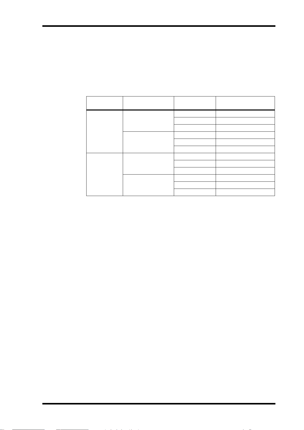
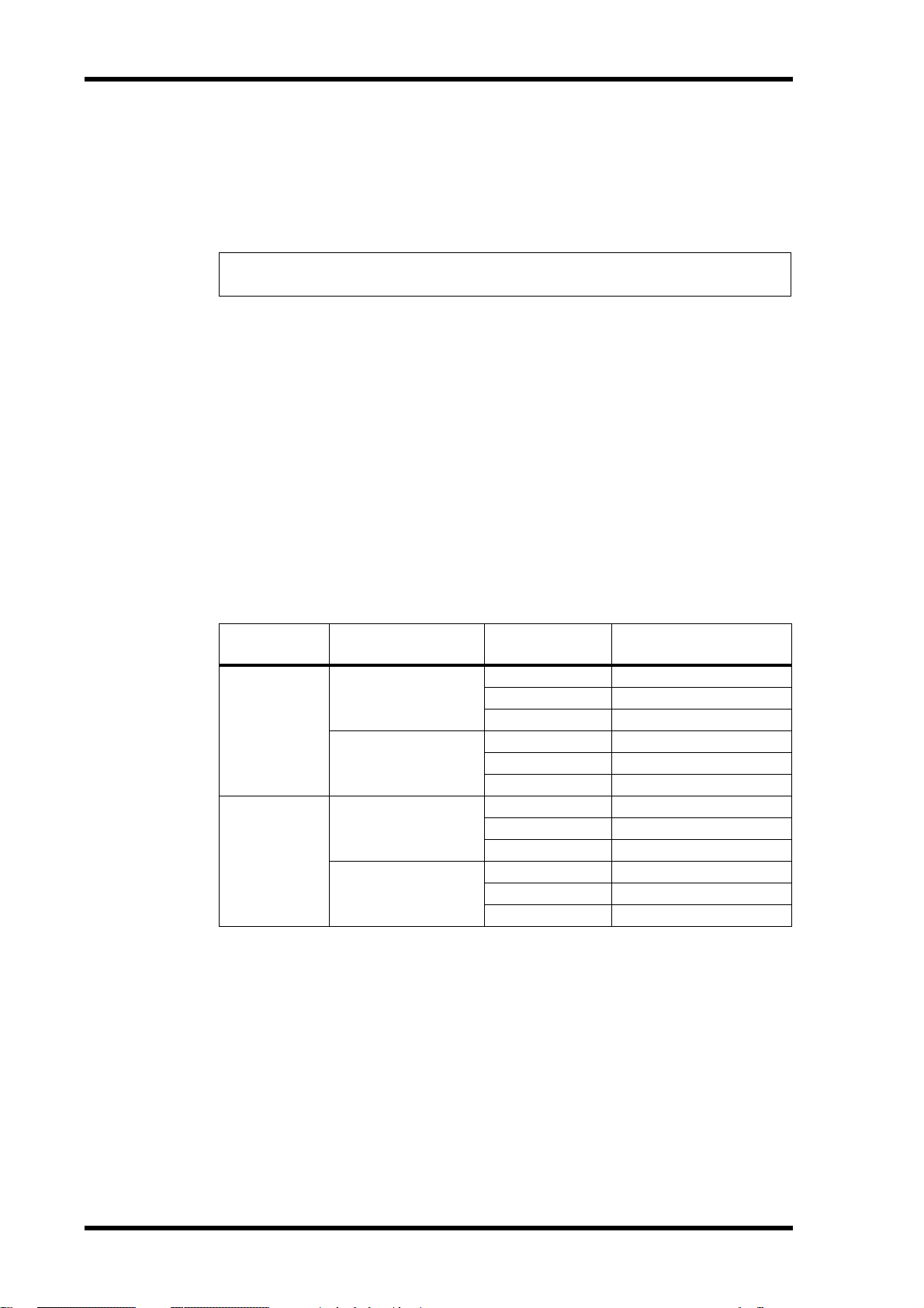
The number of tracks with which seamless punch out monitoring can be used simultaneously is limited by the following factors: recording media (MO or hard disk), sampling rate (48 kHz or 44.1 kHz), and recording resolution (16-, 20-, or 24-bit), as
shown in the following table.
3
Media Sampling Rate
48 kHz
MO
44.1 kHz
48 kHz
Hard Disk
44.1 kHz
Recording
Resolution
24-bit 8
20-bit 9
16-bit 11
24-bit 9
20-bit 10
16-bit 12
24-bit 12
20-bit 15
16-bit 16
24-bit 15
20-bit 16
16-bit 16
Max. No. of Tracks for
Seamless Punch Out
The maximum number of tracks for seamless punch out consists of the number of
tracks previously recorded (i.e., the number of tracks playing back) and the number of
tracks selected for punch in/out recording. For example, the maximum number of
tracks for seamless punch out using an MO disk at 48 kHz/24-bit is eight, so if four
tracks have already been recorded, up to four tracks can be selected for seamless punch
out.
If the maximum number of tracks for seamless punch out is exceeded (i.e., a greater
number tracks are selected for recording), punch out monitoring will not be seamless.
Audio recorded to disk is always seamless.
D24—Version 2.0 Supplement
Page 4
4
Crossfade Modes
Two new Crossfade modes, with variable fade times, are now available for use with
punch in/out recording and part editing. Previously, a variable fade in/out time could
be set to smooth the transition between new and existing material at the punch in/out
points, and the part editing edit points. This option has been kept because it has the
advantage that it affects only playback and the fade time can be changed at anytime,
since the fades are not recorded to disk. With the new Crossfade modes, however, the
fades are recorded to disk, so once recorded, they cannot be changed.
The following procedure explains how to select a Fade mode and fade time.
Press the [UTILITY] button.
1
The UTILITY indicator lights up.
2
Use the JOG/DATA dial to select “FADE MODE,” and then press the [ENTER]
button.
The current mode setting appears on the display.
Use the JOG/DATA dial to select a Fade mode:
3
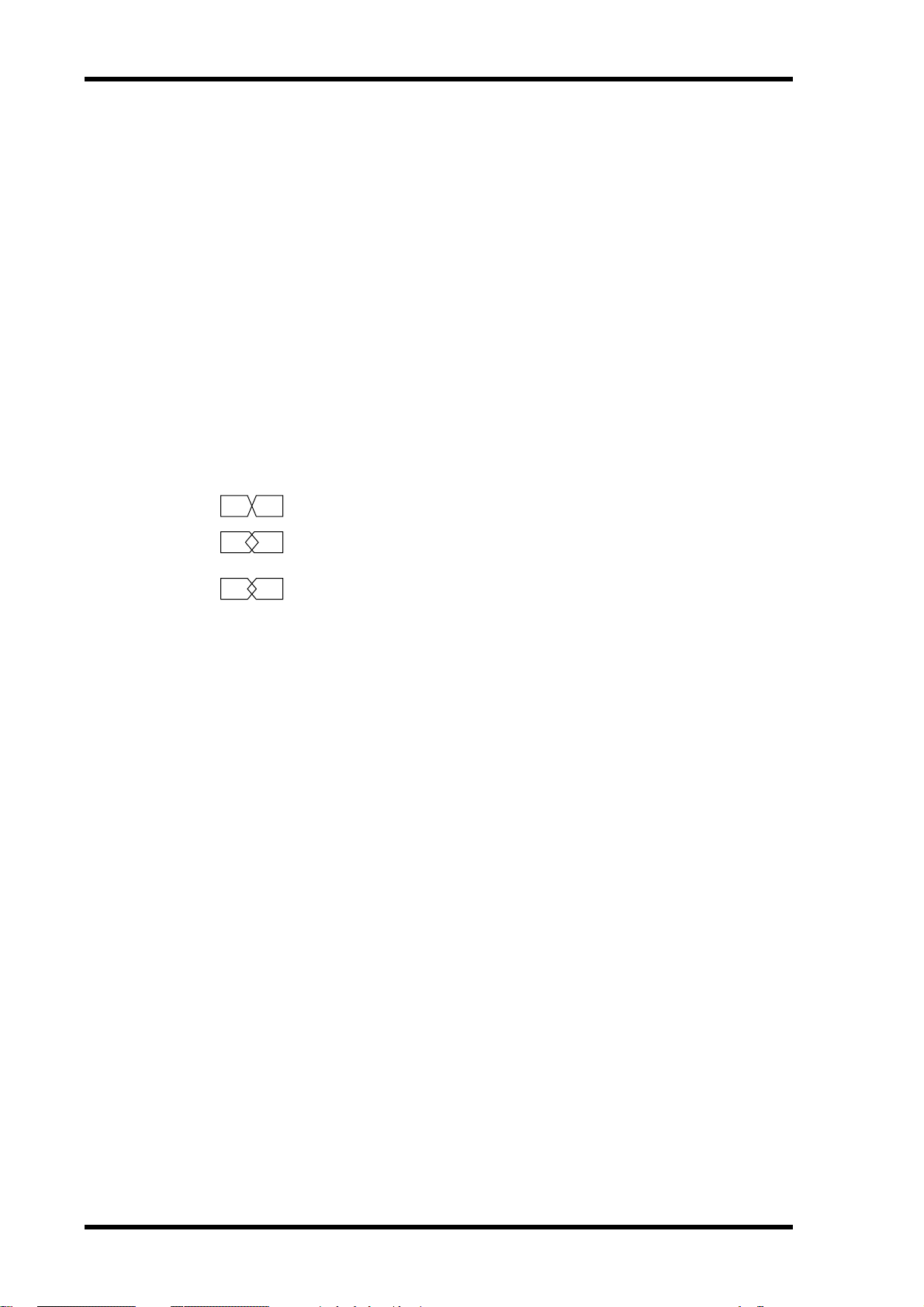
FADE IN/OUT
CROSS FADE1
—Same as previous version.
—Signal levels are at –3 dB at the crossover point (suitable
for music).
CROSS FADE2
—Signal levels are at –6 dB at crossover point (suitable for
sounds consisting essentially of a single, simple tone (e.g., flute, recorder).
4
Press the [ENTER] button to activate your selection, or the [CANCEL] button
to cancel the Fade Mode function.
5
To set the fade time, with the UTILITY indicator still lit, use the JOG/DATA dial
to select “FADE I/O,” and then press the [ENTER] button.
The currently set fade time appears on the display.
Use the JOG/DATA dial to select a fade time: 2, 5, 10, 25, 50, or 100 ms.
6
The default setting is 2 ms.
7
Press the [ENTER] button to activate your selection, or the [CANCEL] button
to cancel the Fade I/O function.
8
Press the [UTILITY] button again to leave utility.
The UTILITY indicator goes out.
Note that if a project that was recorded in the Fade I/O mode is played back in one of
the new Crossfade modes, it will play without the fade in/outs at the punch in/out
points, or part edit points. Therefore, such projects are best played back with the Fade
I/O mode selected.
D24—Version 2.0 Supplement
Page 5

Clearing the A, B, IN & OUT Points
Previously set A, B, LAST REC IN and OUT points can now be cleared.
While holding down the [CANCEL] button, press the [A], [B], [IN], or [OUT]
1
button.
The previously set point is cleared and the corresponding indicator goes out. So long as
the loaded disk is not write-protected, the A, B, LAST REC IN and OUT point information stored on disk is also cleared.
This new function also works on the remote controller.
Using the A, B, IN & OUT Points as Edit Times
The A, B, LAST REC IN and OUT points can now easily be used as the start (ST) and
end (ED) times when using a part edit function, the Time Compression function, or
the Pitch Change function.
5
When the display shows “ST xxxxxxxx” or “ED xxxxxxxx” or “TO xxxxxxxx”
1
and you are required to enter a start, end, or to time, press the [A], [B], [IN],
or [OUT] button.
The time value previously stored for that point is entered and appears on the display. If
no point has been set, no time value is entered.
Using the Solo Buttons to Select Tracks
The SOLO/SELECT buttons can now be used to select the source and destination tracks
for the track and part editing functions and the Time Compression and Pitch Change
functions. (Previously, only the JOG/DATA dial could be used to select tracks.)
1
When the display shows “FROM TR” or “TO TR,” use the SOLO/SELECT buttons to select the source or destination tracks.
As with the JOG/DATA dial, depending on the function being used, tracks can be
selected individually (1–8) or in pairs (1/2, 3/4, 5/6, 7/8).
Note that the JOG/DATA dial must be used to select destination virtual tracks.
Remaining Time
The time remaining can now be checked while recording is in progress. (Previously, it
could be checked only when the D24 had stopped.)
Apogee I/O Cards
The D24 now supports the Apogee AP8AD and AP8DA mini YGDAI I/O cards. (Only
the AP8AD is currently available.)
D24—Version 2.0 Supplement
Page 6

6
Assigning Virtual Tracks Using SOLO & Keypad
When assigning virtual tracks to main tracks, the SOLO/SELECT buttons can now be
used to select the main track. (Previously, only the SHUTTLE/CURSOR could be used
for this.) In addition, the number keypad can now be used to select virtual tracks. (Previously, only the JOG/DATA dial could be used for this.)
1
While the D24 is stopped, press the [V. TRACK SELECT] button.
The V. TRACK SELECT indicator lights up.
The 1st line of the display shows the main track numbers from 1 through 8. The 2nd
line shows the virtual tracks assigned to those main tracks. Initially, each main track is
assigned its respective virtual track 1.
Use the SOLO/SELECT buttons or SHUTTLE/CURSOR ring to select a main
2
track.
The number of the virtual track assigned to the selected main track flashes on the 2nd
line of the display and the corresponding SOLO/SELECT indicator lights up.
Use the number keypad or JOG/DATA dial to assign a virtual track to the
3
selected main track.
Press the [ENTER] button to apply your virtual track settings.
4
“FINISHED” appears on the display for a few seconds and then The V. TRACK SELECT
indicator goes out.
Functions Echoed Across Multiple D24s
In a multiple-unit system, the following settings made on the master D24 are echoed by
the slave D24s. (Previously, these settings were not echoed by the slaves.)
• Setting the A, B, LAST REC IN and OUT points.
• Canceling the A, B, LAST REC IN and OUT points.
• LAST REC IN and OUT points for auto punch in/out recording.
• Setting the LEVEL METER mode—NORMAL or FINE.
Settings other than LEVEL METER mode also work on the remote controller.
Fixing Take 00
When using the Fix Take function to select the take you want to keep after auto punch
in/out recording, the original material (i.e., TAKE 00) can now be selected. (Previously,
TAKE 00 could not be selected, so to revert to the original material you had to fix
another take, exit the Auto Punch function, and then use Undo.) As before, the original
material (i.e., TAKE 00) can be auditioned by using the Audition Take function.
Fix Take cannot be performed from the remote controller or in a multiple-unit system.
Remote ID Conflict Error Message
In a multiple-unit system, if two or more D24s are assigned the same Remote ID, the
error message “RMT ID ERROR” appears when the [CHASE] button is pressed, and
Chase mode cannot be engaged.
D24—Version 2.0 Supplement
Page 7
7
Supplément: V2.0 de mise à jour du D24
Ce document vous décrit comment effectuer la mise à jour à la version 2.0 du D24 et
de la RC-D24 ainsi que les nouvelles caractéristiques et fonctions de cette mise à jour.
Mise à jour du D24
Suivez les instructions ci-dessous pour effectuer la mise à jour du D24. Veillez à utiliser
le disque MO étiqueté “Ver. 2.00 DISK”.
Mettez le D24 hors tension.
1
Remettez ensuite le D24 sous tension.
2
Chargez le disque MO étiqueté “Ver. 2.00 DISK” dans le D24.
3
Quand le message “UNFORMATTED” apparaît à la deuxième ligne de l’écran
4
(ce qui prend environ 10 secondes), appuyez sur le bouton [UTILITY].
FRANÇAIS
Sélectionnez “UPDATE” avec la molette JOG/DATA puis appuyez sur le bouton
5
[ENTER].
Une fois que le message “UPDATE – D24” apparaît, appuyez sur le bouton
6
[ENTER].
Attention: N’appuyez qu’une seule fois sur le bouton [ENTER].
Le message “WAITING” apparaît après environ 10 secondes. 60 secondes plus tard, ce
message disparaît et “TURN OFF” s’affiche. La mise à jour est terminée.
Attention: Ne mettez en aucun cas le D24 hors tension avant que le message “TURN
OFF” ne s’affiche.
Pour vérifier le numéro de la version, mettez d’abord le D24 hors tension puis
7
remettez-le sous tension en maintenant enfoncé le bouton [UTILITY]. L’écran
affiche le numéro de la version comme suit: “V1 200”.
Mise à jour de la RC-D24
La procédure suivante décrit la mise à jour pour la commande à distance RC-D24 du
D24. Veillez à utiliser le disque MO étiqueté “Ver. 2.00 DISK”.
1
Mettez le D24 hors tension.
2
Branchez la RC-D24 au D24.
3
Mettez le D24 sous tension.
Mettez la RC-D24 sous tension.
4
Vérifiez que l’écran de la RC-D24 affiche bien “00:00:00.00”.
5
Chargez le disque MO portant l’étiquette “Ver. 2.00 DISK” dans le D24.
6
Quand le message “UNFORMATTED” apparaît à la deuxième ligne de l’écran
7
(ce qui prend environ 10 secondes), appuyez sur le bouton [UTILITY].
Sélectionnez “UPDATE” avec la molette JOG/DATA puis appuyez sur le bouton
8
[ENTER].
D24—Supplément: Mise à jour à la version 2.0
Page 8
8
Une fois que le message “UPDATE – D24” apparaît, choisissez “RCU” avec la
9
molette JOG/DATA puis appuyez sur le bouton [ENTER].
Le message “WAITING” s’affiche. Le compteur de la RC-D24 et du D24 comptent à
présent de “1/374” jusqu’à “374/374”, ce qui prend environ 120 secondes. Après environ
20 secondes supplémentaires, les boutons de transport de la RC-D24 commencent à clignoter. La mise à jour est ainsi terminée.
Attention: Ne mettez en aucun cas le D24 ni la RC-D24 hors tension avant que les boutons
de transport ne clignotent.
10
Pour vérifier le numéro de la version, mettez le D24 hors tension puis sous
tension; mettez ensuite la RC-D24 sous tension tout en maintenant enfoncé
son bouton [RTN TO ZERO].
L’écran affiche le numéro de version de la RC-D24 comme suit: “200 xxxxxx”.
Ecoute Punch Out sans faille
Au point Punch Out, le circuit d’écoute passe maintenant de manière inaudible du
signal d’entrée au signal de reproduction. (Sur la version précédente, l’écoute était
étouffée pendant un bref instant lors du Punch Out.)
Le nombre de pistes sur lesquelles vous pouvez effectuer simultanément un Punch Out
inaudible dépend des facteurs suivants: support d’enregistrement (disque MO ou disque dur), fréquence d’échantillonnage (48 kHz ou 44,1 kHz) et résolution d’enregistrement (16, 20 ou 24 bits), comme le montre le tableau suivant:
Support
Disque MO
Disque dur
Fréquence
d’échantillonnage
48 kHz
44,1 kHz
48 kHz
44,1 kHz
Résolution
d’enregistrement
24 bits 8
20 bits 9
16 bits 11
24 bits 9
20 bits 10
16 bits 12
24 bits 12
20 bits 15
16 bits 16
24 bits 15
20 bits 16
16 bits 16
Nbre max. de pistes pour
un Punch Out inaudible
Le nombre maximum des pistes disponibles pour le Punch Out inaudible correspond
au nombre de pistes de l’enregistrement précédent (c.-à-d. le nombre de pistes reproduites) et au nombre de pistes sélectionnées pour l’enregistrement Punch In/Out. Par
exemple, le nombre maximum de pistes pour un Punch Out inaudible avec un disque
MO et à 48 kHz/24 bits est de huit, de sorte que si vous avez déjà enregistré quatre pistes, vous pouvez choisir quatre pistes pour effectuer un Punch Out inaudible.
Si vous dépassez le nombre maximum de pistes pour le Punch Out inaudible (c.-à-d. si
vous avez choisi plus de pistes pour l’enregistrement), le Punch Out sera audible à
l’écoute. L’enregistrement des données audio sur disque se fait toujours de manière
impeccable.
D24—Supplément: Mise à jour à la version 2.0
Page 9

Modes Crossfade
Deux nouveaux modes Crossfade avec longueur de transition variable sont maintenant
disponibles pour l’enregistrement Punch In/Out et l’édition de parties. La version précédente permettait d’appliquer un fade in/out de longueur variable afin d’adoucir la
transition entre les anciennes données et les nouvelles données insérées aux points
Punch In/Out ainsi qu’aux points d’édition de partie. Cette option a été conservée en
raison de ses avantages: elle affecte uniquement la reproduction et elle permet de modifier la longueur de fade in/out à tout moment, vu que ces transitions ne sont pas enregistrées sur disque. Dans le cas des nouveaux modes Crossfade, en revanche, les
transitions sont enregistrées sur disque; une fois enregistrées, elles ne peuvent donc pas
être modifiées.
Suivez la procédure ci-dessous pour choisir un mode Fade et régler la longueur de transition.
1 Appuyez sur le bouton [UTILITY].
9
Le témoin UTILITY s’allume.
2 Choisissez “FADE MODE” avec la molette JOG/DATA puis appuyez sur le bou-
ton [ENTER].
Le mode en vigueur apparaît à l’écran.
3 Choisissez un mode Fade avec la molette JOG/DATA:
FADE IN/OUT—Identique à la version précédente.
CROSS FADE1—Le niveau des signaux est de –3 dB au point de transition
(un réglage qui convient bien pour de la musique).
CROSS FADE2—Le niveau des signaux est de –6 dB au point de transition,
soit un réglage adapté à des sons uniques et simples (comme un son de flûte
ou de flûte à bec).
4 Confirmez le mode sélectionné en appuyant sur le bouton [ENTER] ou
appuyez sur le bouton [CANCEL] pour annuler la fonction Fade Mode.
5 Pour régler le temps de transition – quand le témoin UTILITY est toujours
allumé –, choisissez “FADE I/O” avec la molette JOG/DATA puis appuyez sur
le bouton [ENTER].
Le réglage du temps de transition en vigueur est affiché.
6 Choisissez un temps de transition avec la molette JOG/DATA: 2, 5, 10, 25, 50
ou 100 ms.
La valeur par défaut est de 2 ms.
7 Confirmez la valeur choisie en appuyant sur le bouton [ENTER] ou appuyez
sur le bouton [CANCEL] pour annuler la fonction Fade I/O.
8 Appuyez une fois de plus sur le bouton [UTILITY] pour quitter le mode utili-
taire.
Le témoin UTILITY s’éteint.
Notez que si un projet enregistré avec le mode Fade I/O est reproduit dans un des nou-
veaux modes Crossfade, il est joué sans fade in/out aux points Punch In/Out ou aux
points d’édition de partie. Il est donc préférable de reproduire ces projets avec le mode
Fade I/O en question.
D24—Supplément: Mise à jour à la version 2.0
Page 10

10
Effacer les points A, B, IN & OUT
Vous pouvez à présent effacer les points A, B, LAST REC IN et OUT déjà définis.
1 Tout en maintenant enfoncé le bouton [CANCEL], appuyez sur le bouton [A],
[B], [IN] ou [OUT].
Le point défini auparavant est effacé et le témoin correspondant s’éteint. Les informations relatives au point A, B, LAST REC IN ou OUT en question et contenues sur le disque sont aussi effacées, à condition que le disque ne soit pas protégé contre l’écriture.
Cette nouvelle fonction est aussi disponible sur la commande à distance.
Utilisation des points A, B, IN & OUT comme points d’édition
Vous pouvez à présent utiliser les points A, B, LAST REC IN et OUT comme points ST
(start) et ED (end) avec une fonction d’édition de partie, la fonction de compression temporelle (Time Compression) ou la fonction de changement de hauteur (Pitch Change).
1 Quand l’écran affiche “ST xxxxxxxx”, “ED xxxxxxxx” ou “TO xxxxxxxx” et
vous demande de spécifier le point de départ, de fin ou une position, appuyez
sur le bouton [A], [B], [IN] ou [OUT].
La valeur temporelle mémorisée précédemment pour ce point est définie et est affichée
à l’écran. Si aucun point n’a été spécifié, aucune valeur temporelle ne sera définie.
Choix des pistes avec les boutons SOLO/SELECT
Les boutons SOLO/SELECT permettent maintenant de sélectionner les pistes de source
et de destination pour les fonctions d’édition de piste et de parties ainsi que les fonctions Time Compression et Pitch Change. (Sur la version précédente, seule la molette
JOG/DATA permettait de choisir les pistes.)
1 Quand l’écran affiche “FROM TR” ou “TO TR”, choisissez respectivement les
pistes de source ou d’arrivée avec les boutons SOLO/SELECT.
Tout comme pour la molette JOG/DATA, selon la fonction envisagée, les pistes peuvent
être choisies individuellement (1–8) ou par paire (1/2, 3/4, 5/6, 7/8).
Notez que vous devez utiliser la molette JOG/DATA pour choisir les pistes virtuelles de
destination.
Temps résiduel
Vous pouvez à présent vérifier le temps résiduel pendant l’enregistrement. (Sur la version précédente, cette fonction n’était disponible que lorsque le D24 était à l’arrêt.)
Cartes E/S Apogee
Le D24 est maintenant compatible avec les cartes E/S mini YGDAI Apogee AP8AD et
AP8DA. (Seule la carte AP8AD est disponible pour le moment.)
D24—Supplément: Mise à jour à la version 2.0
Page 11

11
Assignation de pistes virtuelles via les boutons SOLO/SELECT & le pavé numérique
Lors de l’assignation de pistes virtuelles aux pistes principales, vous pouvez maintenant
utiliser les boutons SOLO/SELECT pour choisir la piste principale. (Sur la version précédente, seul l’anneau SHUTTLE/CURSOR le permettait.) En outre, le pavé numérique permet maintenant de choisir des pistes virtuelles. (Seule la molette JOG/DATA le
permettait sur la version précédente.)
1 Tant que le D24 est à l’arrêt, appuyez sur le bouton [V. TRACK SELECT].
Le témoin V. TRACK SELECT s’allume.
La première ligne de l’écran indique les numéros de la piste principale de 1 à 8. La
seconde ligne affiche les pistes virtuelles assignées à ces pistes principales. Initialement,
chaque piste principale se voit assigner sa piste virtuelle 1.
2 Utilisez les boutons SOLO/SELECT ou l’anneau SHUTTLE/CURSOR pour choi-
sir une piste principale.
Le numéro de la piste virtuelle assignée à la piste principale sélectionnée clignote sur la
seconde ligne de l’écran et le témoin SOLO/SELECT correspondant s’allume.
3 Utilisez le pavé numérique ou la molette JOG/DATA pour assigner une piste
virtuelle à la piste principale sélectionnée.
4 Appuyez sur le bouton [ENTER] pour confirmer vos réglages de piste virtuelle.
Le témoin V. TRACK SELECT s’éteint et “FINISHED” apparaît quelques secondes à l’écran.
Fonctions répétées par plusieurs D24
Dans un système comprenant plusieurs D24, les réglages suivants effectués sur le D24
maître sont répétés par les D24 esclaves. (Sur la version précédente, ces réglages
n’étaient pas répétés par les esclaves.)
• Réglage des points A, B, LAST REC IN et OUT.
• Annulation des points A, B, LAST REC IN et OUT.
• Points LAST REC IN et OUT pour l’enregistrement Auto Punch In/Out.
• Réglage du mode LEVEL METER —NORMAL ou FINE.
• Les réglages autres que celui du mode LEVEL METER sont aussi disponibles sur la
commande à distance.
Fixer la prise 00
Quand vous utilisez la fonction Fix Take pour choisir la prise que vous allez conserver
après un enregistrement Auto Punch In/Out, vous pouvez maintenant sélectionner les
données originales (à savoir “TAKE 00” ou la prise 00). (Auparavant, vous ne pouviez
pas choisir la prise 00; pour retourner aux données originales, vous deviez donc “fixer”
une autre prise, quitter la fonction Auto Punch puis utiliser la fonction Undo.) Comme
dans la version précédente, vous pouvez écouter les données originales (à savoir la prise
00) avec la fonction Audition Take.
La fonction Fix Take n’est pas disponible sur la commande à distance ni dans un sys-
tème à plusieurs D24.
D24—Supplément: Mise à jour à la version 2.0
Page 12

12
Message d’erreur RMT ID ERROR (conflit
d’adresse de la commande à distance)
Si, au sein d’un système contenant plusieurs D24, le même numéro Remote ID est assigné à plusieurs D24, l’écran affichera le message d’erreur “RMT ID ERROR” quand
vous appuyez sur bouton [CHASE]. Dans ce cas, le mode Chase ne sera pas disponible.
D24—Supplément: Mise à jour à la version 2.0
Page 13

Bedienhinweise für V2.0 des D24
In diesen Hinweisen erfahren Sie, wie man die Version 2.0 des Betriebssystems auf dem
D24 und der RC-D24 installiert und welche neuen Funktionen dann verfügbar sind.
Aktualisieren des D24
Sehen wir uns zuerst an, wie man das Betriebssystem des D24 aktualisiert. Verwenden
Sie hierfür die MO-Scheibe “Ver. 2.00 DISK”.
1 Schalten Sie den D24 aus.
2 Schalten Sie den D24 wieder ein.
3 Legen Sie die MO-Scheibe “Ver. 2.00 DISK” in das Laufwerk des D24.
4 Wenn die Meldung “UNFORMATTED” in der 2. Display-Zeile erscheint (nach
ca. 10 Sekunden), drücken Sie die [UTILITY]-Taste.
5 Wählen Sie mit dem JOG/DATA-Rad “UPDATE” und drücken Sie die [ENTER]-Taste.
13
DEUTSCH
6 Wenn die Meldung “UPDATE – D24” erscheint, müssen Sie die [ENTER]-Taste
drücken.
Warnung: Drücken Sie die [ENTER]-Taste nur jeweils ein Mal.
Nach ungefähr 10 Sekunden erscheint die Meldung “WAITING”. Nach weiteren 60
Sekunden erscheint die Aufforderung “TURN OFF”. Die Aktualisierung ist nun beendet.
Warnung: Schalten Sie den D24 erst aus, wenn die Meldung “TURN OFF” erscheint.
7 Um die Versionsnummer kontrollieren zu können, müssen Sie den D24 zuerst
ausschalten und danach die [UTILITY]-Taste gedrückt halten, während Sie den
D24 wieder einschalten. Die Versionsnummer wird nun folgendermaßen
angezeigt: “V1 200”.
Aktualisieren der RC-D24
Sehen wir uns nun an, wie man die Fernbedienung des D24, d.h. die RC-D24, aktualisiert. Hierfür brauchen Sie die MO-Scheibe “Ver. 2.00 DISK”.
1 Schalten Sie den D24 aus.
2 Schließen Sie die RC-D24 an den D24 an.
3 Schalten Sie den D24 ein.
4 Schalten Sie die RC-D24 ein.
5 Schauen Sie nach, ob der Wert “00:00:00.00” im Display der RC-D24
erscheint.
6 Legen Sie die MO-Scheibe “Ver. 2.00 DISK” in das Laufwerk des D24.
7 Wenn die Meldung “UNFORMATTED” in der 2. Zeile erscheint (das dauert
ungefähr 10 Sekunden), drücken Sie die [UTILITY]-Taste.
8 Wählen Sie mit dem JOG/DATA-Rad “UPDATE” und drücken Sie die
[ENTER]-Taste.
D24—Version 2.0 Bedienhinweise
Page 14

14
9 Sobald die Meldung “UPDATE – D24” erscheint, wählen Sie mit dem JOG/
DATA-Rad “RCU” und drücken die [ENTER]-Taste.
Nun erscheint die Meldung “WAITING” im Display. Das Zählwerk der RC-D24 und
des D24 zählen nun von “1/374” bis “374/374”. Das dauert ungefähr 120 Sekunden.
Nach weiteren 20 Sekunden beginnen die Transporttasten der RC-D24 zu blinken. Das
bedeutet, dass das Betriebssystem aktualisiert ist.
Warnung: Schalten Sie den D24 und die RC-D24 erst aus, wenn die Transporttasten zu
blinken beginnen.
10 Um die Versionsnummer zu kontrollieren, müssen Sie zuerst den D24 aus-
schalten. Halten Sie anschließend die [RTN TO ZERO]-Taste der RC-D24
gedrückt, während Sie die RC-D24 einschalten.
Die Versionsnummer der RC-D24 erscheint nun wie folgt im Display: “200 xxxxxx”.
Nahtlose Punch Out-Überwachung
An der OUT-Position (Ausstiegspunkt) schalten die Abhörschaltkreise nun nahtlos um
vom Eingangs- zum Wiedergabesignal. (Bisher wurde der betreffende Kanal beim
Umschalten kurz stummgeschaltet.)
Die Anzahl der Spuren, für welche diese nahtlose Umschaltung durchgeführt werden
kann, richtet sich nach folgenden Faktoren: Datenträger (MO-Scheibe oder Festplatte),
Sampling-Frequenz (48 kHz oder 44,1 kHz) und Wortbreite/Auflösung (16, 20 oder 24
Bit). Siehe auch folgende Tabelle:
Medium Sampling-Frequenz
48 kHz
MO
44,1 kHz
48 kHz
Festplatte
44,1 kHz
Wortbreite/
Auflösung
24 Bit 8
20 Bit 9
16 Bit 11
24 Bit 9
20 Bit 10
16 Bit 12
24 Bit 12
20 Bit 15
16 Bit 16
24 Bit 15
20 Bit 16
16 Bit 16
Max. Anzahl der Spuren
für nahtloses Aussteigen
Die maximale Anzahl der Spuren für ein nahtloses Aussteigen umfasst die Anzahl der
bereits bespielten Spuren (die auch abgespielt werden) sowie die Anzahl der Spuren, die
für die Punch In/Out-Aufnahme aktiviert wurden. Beispiel: bei Verwendung eines
48 kHz/24 Bit-Songs auf einer MO-Scheibe beträgt die maximale Anzahl der Spuren
acht; wenn Sie also bereits vier Spuren bespielt haben, können Sie vier weitere Spuren
für ein nahtloses Punch Out aktivieren.
Wenn mehr als die zulässige Anzahl der Spuren aktiv sind (d.h. wenn Sie mehr Spuren
aufnahmebereit gemacht haben), ist die Punch Out-Überwachung nicht mehr nahtlos.
Das hat aber keinen Einfluss auf die aufgezeichneten Daten, weil der Ausstieg auf der
Datenebene immer nahtlos erfolgt.
D24—Version 2.0 Bedienhinweise
Page 15

Crossfade-Modi (Überblendungen)
Es stehen nun zwei weitere Crossfade-Modi mit einstellbarer Überblendungsdauer zur
Verfügung. Diese können beim Ein-/Aussteigen und beim Editieren der Parts verwendet werden. Bisher konnte die Fade In/Out-Dauer wunschgemäß eingestellt werden,
um einen nahtlosen Übergang zwischen dem neu aufgezeichneten und dem bereits
vorhandenen Audiomaterial zu gewährleisten. Das galt auch für die Part Edit-Positionen. Diese Option ist auch weiterhin vorhanden, weil sie den Vorteil bietet, dass sie nur
die Wiedergabe beeinflusst und dass die Ein-/Ausblendung zudem nachträglich verlängert/verkürzt werden kann, weil die “physische” Überblendung nicht auf der Festplatte
gespeichert wird. Die neuen Crossfade-Modi hingegen bewirken eine tatsächliche
Änderung des Audiomaterials. Solche Eingriffe lassen sich später also nicht mehr
ändern.
Der Fade-Modus sowie die Fade-Dauer stellt man folgendermaßen ein:
1 Drücken Sie die [UTILITY]-Taste.
Die UTILITY-Diode leuchtet.
2 Wählen Sie mit dem JOG/DATA-Rad “FADE MODE” und drücken Sie die
[ENTER]-Taste.
Die aktuelle Modus-Einstellung erscheint nun im Display.
15
3 Wählen Sie mit dem JOG/DATA-Rad den Fade-Modus:
FADE IN/OUT—Dasselbe Verhalten wie in der vorigen Version.
CROSS FADE1—Der Signalübergang befindet sich an einer –3 dB-Stelle
(eignet sich für Musik).
CROSS FADE2—Der Signalübergang befindet sich an einer Stelle, wo der
Signalpegel –6 dB beträgt (eignet sich für Signale, die aus einem einzigen
und wenig komplexen Ton bestehen, z.B. Flöte, Blockflöte).
4 Drücken Sie die [ENTER]-Taste, um Ihre Wahl zu bestätigen bzw. die
[CANCEL]-Taste, wenn Sie doch keinen anderen Fade-Modus wählen möchten.
5 Um die Fade-Dauer einzustellen, müssen Sie –solange die UTILITY-Diode noch
leuchtet– mit dem JOG/DATA-Rad “FADE I/O” wählen und anschließend die
[ENTER]-Taste drücken.
Die aktuell eingestellte Fade-Dauer erscheint nun im Display.
6 Wählen Sie mit dem JOG/DATA-Rad die Fade-Dauer: 2, 5, 10, 25, 50 oder
100 ms.
Die Vorgabe lautet “2 ms”.
7 Drücken Sie die [ENTER]-Taste, um Ihre Wahl zu bestätigen bzw. die
[CANCEL]-Taste, um die Fade I/O-Funktion wieder zu verlassen.
8 Drücken Sie die [UTILITY]-Taste noch einmal, um diesen Betrieb wieder zu ver-
lassen.
Die UTILITY-Diode erlischt.
Bedenken Sie, dass ein Projekt, das im “alten” Fade I/O-Modus erstellt wurde und nun
in einem neuen Crossfade-Modus gefahren wird, an der Ein- und Ausstiegsstelle bzw,
an der ST-/ED-Position der Part Edit-Funktion ohne Fade-In/Out abgespielt wird. Für
mit einer älteren Version aufgenommene Projekte wählen Sie am besten den
Fade I/O-Modus.
D24—Version 2.0 Bedienhinweise
Page 16

16
Löschen der A-, B-, IN- & OUT-Position
Zuvor programmierte Locator-Punkte (A, B, LAST REC IN und OUT) können ab
sofort auch gelöscht werden.
1 Halten Sie die [CANCEL]-Taste gedrückt, während Sie die [A]-, [B]-, [IN]- oder
[OUT]-Taste betätigen.
Die betreffende Position wird gelöscht und die dazugehörige Diode erlischt. Wenn die
eingelegte Disk nicht schreibgeschützt ist, wird die A-, B-, LAST REC IN- oder
OUT-Position auch von der Disk gelöscht.
Diese neue Funktion ist auch für die Fernbedienung belegt.
Verwendung der Positionen A, B, IN & OUT als Editierwerte
Die für A, B, LAST REC IN und OUT gespeicherten Positionen können ab sofort auch
als Beginn- (ST) und (ED) End-Punkt für die Part Edit-Funktionen sowie für Time
Compression und Pitch Change verwendet werden.
1 Wenn im Display “ST xxxxxxxx”, “ED xxxxxxxx” oder “TO xxxxxxxx” ange-
zeigt wird, weil Sie eine Start-, End- oder Zielposition eingeben müssen, können Sie letzteres nun tun, indem Sie die Taste [A], [B], [IN] oder [OUT]
drücken.
Der für die betreffende Taste gespeicherte Wert wird übernommen und erscheint nun
im Display. Wenn Sie noch keine Position gespeichert haben, wird auch kein Wert eingegeben.
Verwendung der SOLO-Tasten für die Anwahl der Spuren
Ab sofort können die SOLO/SELECT-Tasten für die Anwahl der Quell- und Zielspur
verwendet werden. Das ist für folgende Funktionen belegt: Track Edit, Part Edit, Time
Compression und Pitch Change. (Bisher konnten die Spuren nur mit dem JOG/
DATA-Rad gewählt werden.)
1 Wenn im Display “FROM TR” oder “TO TR” angezeigt wird, können Sie mit
den SOLO/SELECT-Tasten die Quell- und Zielspur(en) wählen.
Genau wie bei Verwendung des JOG/DATA-Rades können die Spuren, je nach Funktion, entweder einzeln (1~8) oder als Paare (1/2, 3/4, 5/6, 7/8) gewählt werden.
Virtuelle Spuren können hingegen nur mit dem JOG/DATA-Rad gewählt werden.
Verbleibende Aufnahmedauer
Die verbleibende Aufnahmedauer kann nun auch bei laufender Aufnahme kontrolliert
werden. (Bisher ging das nur, wenn der D24 zuvor gestoppt wurde.)
D24—Version 2.0 Bedienhinweise
Page 17

Apogee E/A-Platinen
Der D24 unterstützt nun auch die mini-YGDAI-Platinen AP8AD und AP8DA von
Apogee. (Momentan ist aber erst die AP8AD erhältlich.)
Zuordnen der virtuellen Spuren mit SOLO & Zehnertastenfeld
Zum Zuordnen der virtuellen Spuren zu den Spurnummern können Sie die
gewünschte Hauptspur nun mit den SOLO/SELECT-Tasten auswählen. (Bisher ging
das nur mit dem SHUTTLE/CURSOR-Rad.) Die virtuellen Spuren können ab sofort
über das Zehnertastenfeld gewählt werden. (Bisher musste man dafür das JOG/
DATA-Rad verwenden.)
1 Halten Sie den D24 an und drücken Sie die [V. TRACK SELECT]-Taste.
Die V. TRACK SELECT-Diode leuchtet.
In der ersten Display-Zeile erscheinen nun die Nummern der Hauptspuren 1~8. In
der 2. Zeile werden die Nummern der virtuellen Spuren angezeigt, die aktuell den
Hauptspuren zugeordnet sind. Anfangs verwenden alle Hauptspuren ihre virtuelle
Spur “1”.
17
2 Wählen Sie mit den SOLO/SELECT-Tasten oder dem SHUTTLE/CURSOR-Ring
die benötigte Hauptspur.
Die Nummer der dieser Hauptspur zugeordneten virtuellen Spur in der zweiten Zeile
beginnt zu blinken. Außerdem leuchtet die entsprechende SOLO/SELECT-Diode.
3 Ordnen Sie der gewählten Hauptspur mit dem Zehnertastenfeld oder dem
JOG/DATA-Rad die gewünschte virtuelle Spur zu.
4 Drücken Sie die [ENTER]-Taste, um die Zuordnung der virtuellen Spur zu
bestätigen.
Im Display erscheint nun kurz die Meldung “FINISHED”. Anschließend erlischt die V.
TRACK SELECT-Diode wieder.
Funktionen, die von den D24-Einheiten weitergeleitet werden
In einer Anlage mit mehreren Einheiten werden folgende auf dem D24-Master durchgeführten Einstellungen auch zu den übrigen D24-Einheiten (Slaves) weitergeleitet.
(Bisher war das nicht der Fall.)
• Einstellung der Positionen A, B, LAST REC IN und OUT.
• Löschen der Positionen A, B, LAST REC IN und OUT.
• Einstellung der Positionen LAST REC IN und OUT für die Auto Punch In/Out-Aufnahme.
• Anwahl des LEVEL METER-Modus’ —NORMAL oder FINE.
Alle Einstellungen bis auf jene des LEVEL METER-Modus’ funktionieren auch auf der
Fernbedienung.
D24—Version 2.0 Bedienhinweise
Page 18

18
Auswahl von Take 00 (Fix Take 00)
Wenn Sie mit der Fix Take-Funktion nach mehreren Auto Punch-Aufnahmedurchgängen den besten Take wählen, können Sie ab sofort auch wieder die ursprüngliche Fassung (d.h. TAKE 00) wählen, wenn diese doch die beste ist. (Bisher konnte TAKE 00
nicht gewählt werden, so dass man sich provisorisch für einen anderen entscheiden, die
Auto Punch-Funktion verlassen und anschließend mit Undo wieder zum Original
zurückkehren musste.) Das Original (TAKE 00) kann jedoch mit der Audition
Take-Funktion auch weiterhin abgespielt werden.
Fix Take ist auf der Fernbedienung nicht belegt, wenn Sie mit mehreren D24-Einheiten
arbeiten.
Fehlermeldung “RMT ID Conflict”
Wenn in einer Anlage mit mehreren D24-Einheiten zwei oder mehr D24-Einheiten dieselbe Remote ID-Nummer haben, erscheint die Fehlermeldung “RMT ID ERROR”,
sobald Sie die [CHASE]-Taste drücken. Der Chase-Modus kann dann nicht aktiviert
werden.
D24—Version 2.0 Bedienhinweise
Page 19

Suplemento V2.0 para la D24
En este documento se explica cómo actualizar la D24 y el RC-D24 hasta la versión 2.0,
y se indican las nuevas características y funciones que proporciona la actualización.
Actualización de la D24
En el procedimiento siguiente se explica cómo actualizar la D24. Cerciórese de utilizar
el disco MO con la etiqueta “Ver. 2.00 DISK”.
1 Desconecte la alimentación de la D24.
2 Conecte la alimentación de la D24.
3 Inserte el disco MO con la etiqueta “Ver. 2.00 DISK” en la D24.
4 Cuando aparezca el mensaje “UNFORMATTED” en la segunda línea del visua-
lizador (que tardará unos 10 segundos), presione el botón [UTILITY].
5 Utilice el mando JOG/DATA para seleccionar “UPDATE”, y después presione
el botón [ENTER].
19
ESPAÑOL
6 Cuando aparezca el mensaje “UPDATE – D24”, presione el botón [ENTER].
Advertencia: No presione el botón [ENTER] más de una vez.
Después de unos 10 segundos, aparecerá el mensaje “WAITING”. Después de otros 60
segundos el mensaje cambiará a “TURN OFF”. De esta forma habrá finalizado el procedimiento de actualización.
Advertencia: No desconecte la alimentación de la D24 antes de que aparezca el mensaje
“TURN OFF”.
7 Para comprobar el número de versión, desconecte en primer lugar la alimen-
tación de la D24, y después, manteniendo pulsado el botón [UTILITY],
conecte la alimentación de la D24. El número de versión aparecerá en el visualizador de la forma siguiente: “V1 200”.
Actualización del RC-D24
En el procedimiento siguiente se explica cómo actualizar el controlador remoto de la
D24, el RC-D24. Cerciórese de utilizar el disco MO con la etiqueta “Ver. 2.00 DISK”.
1 Desconecte la alimentación de la D24.
2 Conecte el RC-D24 a la D24.
3 Conecte la alimentación de la D24.
4 Conecte la alimentación del RC-D24.
5 Compruebe si en el visualizador del RC-D24 aparece “00:00:00.00”.
6 Inserte el disco MO con la etiqueta “Ver. 2.00 DISK” en la D24.
7 Cuando aparezca el mensaje “UNFORMATTED” en la segunda línea del visua-
lizador (que tardará unos 10 segundos), presione el botón [UTILITY].
8 Utilice el mando JOG/DATA para seleccionar “UPDATE”, y después presione
el botón [ENTER].
D24—Suplemento V2.0
Page 20

20
9 Cuando aparezca el mensaje “UPDATE – 24D”, utilkice el mando JOG/DATA
para seleccionar “RCU”, y después presione el botón [ENTER].
Aparecerá el mensaje “WAITING”. El RC-D24 y la D24 contarán hacia arriba desde
1/374" a “374/374”, lo que indica que se tardarán unos 120 segundos. Después de otros
20 segundos, comenzarán a parpadear los botones de transporte del RC-D24. El procedimiento de actualización habrá finalizado.
Advertencia: No desconecte la alimentación de la D24 ni del RC-D24 antes de que empiecen a parpadear los botones de transporte.
10 Para comprobar el número de versión, desconecte y vuelva a conectar en pri-
mer lugar la alimentación de la D24, y después, manteniendo pulsado el
botón [RTN TO ZERO] del RC-D24, conecte la alimentación del RC-D24.
El número de versión del RC-D24 aparecerá en el visualizador de la forma siguiente:
“200 xxxxxx”.
Escucha de salida de grabación ininterrumpida
En el punto de salida de grabación, los circuitos de monitoreo cambian ahora de
entrada a reproducción sin interrupción. (Anteriormente, la escucha se cortaba
durante un instante cuando se producía la salida de grabación.)
El número de pistas con las que podrá utilizarse simultáneamente la escucha de salida
de grabación ininterrumpida está limitado por los factores siguientes: medio de grabación (disco MO o duro), frecuencia de muestreo (48 kHz o 44,1 kHz), y la resolución
de grabación (16, 20, o 24 bits), como se muestra en la tabla siguiente
Num. máx. de pistas para
la salida de grabación
ininterrumpida
Medio
Disco MO
Disco duro
Frecuencia de
muestreo
48 kHz
44,1 kHz
48 kHz
44,1 kHz
Resolución de
grabación
24-bit 8
20-bit 9
16-bit 11
24-bit 9
20-bit 10
16-bit 12
24-bit 12
20-bit 15
16-bit 16
24-bit 15
20-bit 16
16-bit 16
El número máximo de pistas para la salida de grabación ininterrumpida se compone del
número de pistas previamente grabadas (es decir, el número de pistas en reproducción)
y el número de pistas seleccionadas para la grabación con entrada/salida. Por ejemplo, el
número máximo de pistas para la salida de grabación ininterrumpida utilizando un
disco MO a 48 kHz/24 bits es de ocho, por lo que si ya se han grabado cuatro pistas,
podrán seleccionarse hasta cuatro pistas para la salida de grabación ininterrumpida.
D24—Suplemento V2.0
Si se sobrepasa el número máximo de pistas para la salida de grabación ininterrumpida
(es decir, se selecciona un número mayor de pistas para grabación), la escucha de salida
de grabación no será ininterrumpida. El sonido grabado en el disco será siempre ininterrumpido.
Page 21

Modos de desvanecimiento cruzado
Ahora están disponibles dos nuevos modos de desvanecimiento cruzado, con tiempos
de desvanecimiento variable para utilizarse en la grabación con entrada/salida y edición
de partes. Anteriormente, podría ajustarse un tiempo de entrada/salida de desvanecimiento variable para suavizar la transición entre material nuevo y existente en los puntos de entrada/salida de grabación, y los puntos de edición de partes. Esta opción se ha
mantenido porque posee la ventaja de que afecta solamente la reproducción y el tiempo
de desvanecimiento puede cambiarse en cualquier momento, ya que los desvanecimientos no se graban en el disco. Sin embargo, con los nuevos modos de desvanecimiento cruzado, los desvanecimientos se graban en el disco, por lo que una vez
grabados, no podrán cambiarse.
En el procedimiento siguiente se explica cómo seleccionar un modo de desvanecimiento y el tiempo de desvanecimiento.
1 Presione el botón [UTILITY].
Se encenderá el indicador UTILITY.
2 Utilice el mando JOG/DATA para seleccionar “FADE MODE”, y después pre-
sione el botón [ENTER].
En el visualizador aparecerá el ajuste del modo actual.
21
3 Utilice el mando JOG/DATA para seleccionar el modo de desvanecimiento:
FADE IN/OUT — Igual que en la versión anterior.
CROSS FADE1 — Los niveles de la señal están a –3 dB en le punto de cruce
(adecuado para música).
CROSS FADE2 — Los niveles de señal están a –6 dB en el punto de cruce
(adecuado para sonidos compuestos esencialmente de un solo tono sencillo
(p. ej., flauta, grabadora).
4 Presione el botón [ENTER] para activar su selección, o el botón [CANCEL] para
cancelar la función de modo de desvanecimiento.
5 Para ajustar el tiempo de desvanecimiento, con el indicador UTILITY todavía
encendido, utilice el mando JOG/DATA para seleccionar “FADE I/O”, y después presione el botón [ENTER].
En el visualizador aparecerá el tiempo de desvanecimiento actualmente ajustado.
6 Utilice el mando JOG/DATA para seleccionar el tiempo de desvanecimiento:
2, 5, 10, 25, 50, o 100 ms.
El ajuste predeterminado es 2 ms.
7 Presione el botón [ENTER] para activar su selección, o el botón [CANCEL] para
cancelar la función de entrada/salida de desvanecimiento.
8 Para abandonar la utilidad, vuelva a presionar el botón [UTILITY].
El indicador UTILITY se apagará.
Tenga en cuenta que si un proyecto grabado en el modo de entrada/salida de desvane-
cimiento se reproduce en uno de los nuevos modos de desvanecimiento cruzado, se
reproducirá sin entradas/salidas de desvanecimiento en los puntos de entrada/salida, o
en los puntos de edición de partes. Por lo tanto, tales proyectos se reproducirán mejor
con el modo de entrada/salida de desvanecimiento seleccionado.
D24—Suplemento V2.0
Page 22

22
Borrado de los puntos A, B, IN y OUT
Ahora podrán borrarse los puntos A, B, LAST REC IN y OUT previamente establecidos.
1 Manteniendo pulsado el botón [CANCEL], presione el botón [A], [B], [IN], u
[OUT].
El punto previamente establecido se borrará, y el indicador correspondiente se apagará.
Mientras el disco cargado no esté protegido contra escritura, se borrará también la
información sobre los puntos A, B, LAST REC IN y OUT almacenada en el disco.
Esta nueva función también trabajará con el controlador remoto.
Utilización de los puntos A, B, IN y OUT como tiempos de edición
Los puntos A, B, LAST REC IN y OUT podrán utilizarse fácilmente ahora como los
tiempos de inicio (ST) y finalización (ED) cuando utilice la función de edición de una
parte, la función de compresión de tiempo, o la función de cambio de diapasón.
1 Cuando el visualizador muestre “ST xxxxxxxx”, “ED xxxxxxxx”, o “TO
xxxxxxxx” y usted tenga que introducir un tiempo de inicio, finalización, o
hasta, presione el botón [A], [B], [IN], u [OUT].
El valor de tiempo previamente almacenado para tal punto se introducirá y aparecerá
en el visualizador. Si no se había introducido ningún punto, no se introducirá valor de
tiempo.
Utilización de los botones de solo para seleccionar pistas
Los botones SOLO/SELECT podrán utilizarse ahora para seleccionar las pistas fuente y
de destino para las funciones de edición de pistas y partes, y para las funciones de compresión de tiempo y cambio de diapasón. (Anteriormente solamente podría utilizarse
el mando JOG/DATA para seleccionar las canciones.)
1 Cuando el visualizador muestre “FROM TR” o “TO TR”, utilice los botones
SOLO/SELECT para seleccionar las pistas fuente y de destino.
Como con el mando JOG/DATA, dependiendo de la función que esté utilizando, las
canciones podrán seleccionarse individualmente (1–8) o en pares (1/2, 3/4, 5/6, 7/8).
Tenga en cuenta que el mando JOG/DATA tendrá que utilizarse para seleccionar pistas
virtuales de destino.,
Tiempo restante
D24—Suplemento V2.0
Ahora podrá comprobarse el tiempo restante mientras esté realizándose la grabación.
(Anteriormente, solamente podía comprobarse con la D24 parada.)
Page 23

23
Tarjetas de entrada/salida Apogee
La D24 es compatible ahora con las minitarjetas de entrada/salida Apogee AP8AD y
AP8DA YGDAI I/O. (Actualmente sólo está disponible la AP8AD.)
Asignación de pistas virtuales utilizando SOLO y el teclado
Cuando asigne pistas virtuales a pistas principales, los botones SOLO/SELECT podrán
utilizarse ahora para seleccionar la pista principal. (Anteriormente, para esto solamente
podía utilizarse SHUTTLE/CURSOR.) Además, ahora podrá utilizarse el teclado
numérico para seleccionar pistas virtuales. (Anteriormente, para esto solamente podía
utilizarse el mando JOG/DATA.)
1 Con la D24 parada, presione el botón [V. TRACK SELECT].
El indicador V. TRACK SELECT se encenderá.
La primera línea del visualizador muestra los números de las pistas principales de 1 a 8.
La segunda línea muestra las pistas virtuales asignadas a tales pistas principales. Inicialmente, cada pista principal tiene asignada su respectiva pista virtual 1.
2 Utilice los botones SOLO/SELECT o el anillo SHUTTLE/CURSOR para seleccio-
nar una pista principal.
El número de la pista virtual asignada a la pista principal seleccionada parpadeará en la
segunda línea del visualizador, y se encenderá el indicador SOLO/SELECT correspondiente.
3 Utilice el teclado numérico o el mando JOG/DATA para asignar una pista vir-
tual a la pista principal seleccionada.
4 Presione el botón [ENTER] para aplicar sus ajustes de pistas virtuales.
En el visualizador aparecerá “FINISHED” durante algunos segundos y después se apagará el indicador V. TRACK SELECT.
Funciones con repercusión a través de múltiples D24
En un sistema de múltiples unidades, los ajustes siguientes realizados en la D24 principal tendrán repercusión en las D24 subordinadas. (Anteriormente, estos ajustes no
tenían repercusión en las unidades subordinadas.)
• Ajuste de los puntos A, B, LAST REC IN y OUT.
• Cancelación de los puntos A, B, LAST REC IN y OUT.
• Puntos LAST REC IN y OUT para grabación con entrada/salida automática
• Ajuste del modo LEVEL METER — NORMAL o FINE.
Los ajustes que no sean LEVEL METER también trabajarán con el controlador remoto.
D24—Suplemento V2.0
Page 24

24
Fijación de toma 00
Cuando utilice la función de fijación de toma para seleccionar la toma que desee guardar después de la grabación con entrada/salida automática, ahora podrá seleccionar el
material original (es decir, TAKE 00). (Anteriormente, la toma TAKE 00 no podía seleccionarse, por lo que para volver al material original usted tenía que fijar otra toma,
salida de la función de grabación con entrada/salida automática, y después utilizar la
función de deshacer.) Como antes, el material original (es decir, TAKE 00) podrá revisarse utilizando la función de revisión de toma.
La fijación de toma no podrá realizarse desde el controlador remoto ni en un sistema
de múltiples unidades.
Mensaje de error de conflicto de identificación
de unidad remota
En un sistema de múltiples unidades, si dos o más D24 tienen asignado el mismo
código de identificación de unidad remota, cuando presione el botón [CHASE] aparecerá el mensaje de error “RMT ID ERROR”, y no podrá activarse el modo de persecución.
IP 24 Printed in Japan
YAMAHA CORPORATION
Pro Audio & Digital Musical Instrument Division
P.O. Box 3, Hamamatsu, 430-8651, Japan
 Loading...