

Yamaha RX-E400, CDX-E400 User Manual

RX-E400
GB
CRX-E400
Récepteur/Lecteur CD
CDX-E400
Receiver/CD Player
OWNER’S MANUAL
MODE D’EMPLOI
BEDIENUNGSANLEITUNG
BRUKSANVISNING
MANUALE DI ISTRUZIONI
MANUAL DE INSTRUCCIONES
GEBRUIKSAANWIJZING

CAUTION: READ THIS BEFORE OPERATING THIS UNIT
1 To assure the finest performance, please read this
manual carefully. Keep it in a safe place for future
reference.
2 Install this unit in a well ventilated, cool, dry, clean
place away from direct sunlight, heat sources, vibration,
dust, moisture or cold. In a cabinet, allow about 10 cm
(4 in.) of free space all around RX-E400 for adequate
ventilation.
3 Locate this unit away from other electrical appliances,
motors, or transformers to avoid humming sounds.
4 Do not expose this unit to sudden temperature changes
from cold to hot, nor locate this unit in an environment
with high humidity (i.e., a room with a humidifier) to
prevent condensation inside this unit, which may cause
an electrical shock, fire, damage to this unit, and/or
personal injury.
5 Avoid installing this unit in a location where foreign
objects may fall onto this unit or where this unit may be
exposed to liquid dripping or splashing. On the top of
this unit, do not place:
• Other components, as they may cause damage and/or
discoloration on the surface of this unit.
• Burning objects (i.e., candles), as they may cause fire,
damage to this unit, and/or personal injury.
• Containers with liquid in them, as they may fall, spilling
the liquid and causing an electrical shock to the user
and/or damage to this unit.
6 Do not cover this unit with a newspaper, tablecloth,
curtain, etc. in order not to obstruct heat radiation. If the
temperature inside this unit rises, it may cause fire,
damage to this unit, and/or personal injury.
7 Do not plug in this unit to a wall outlet until all
connections are complete.
8 Do not operate this unit upside-down. It may overheat,
possibly causing damage.
9 Do not use excessive force on switches, knobs and/or
cords.
10 When disconnecting the power cord from the wall
outlet, grasp the plug; do not pull the cord.
11 Do not clean this unit with chemical solvents; this might
damage the finish. Use a clean, dry cloth.
12 Use only the voltage specified on this unit. Using this
unit with a higher voltage than specified is dangerous
and may cause fire, damage to this unit, and/or personal
injury. YAMAHA will not be held responsible for any
damage resulting from use of this unit with a voltage
other than as specified.
13 To prevent damage by lightning, disconnect the power
cord from the wall outlet during an electrical storm.
14 Do not attempt to modify or fix this unit. Contact
qualified YAMAHA service personnel when any service
is needed. The cabinet should never be opened for any
reason.
15 When not planning to use this unit for long periods of
time (i.e., vacation), disconnect the AC power plug from
the wall outlet.
16 Be sure to read the “Troubleshooting” section on
common operating errors before concluding that this
unit is faulty.
17 Before moving this unit, press STANDBY/ON to set the
unit in standby mode, then disconnect the AC power
plug from the wall outlet.
18 VOLTAGE SELECTOR (General model only)
The VOLTAGE SELECTOR on the rear panel of this
unit must be set for your local main voltage BEFORE
plugging into the AC main supply. Voltages are 110/120/
220/240 V AC, 50/60 Hz.
To reduce the risk of fire or electric shock, do not
expose this appliance to rain or moisture.
The unit is not disconnected from the AC power source
as long as it is connected to the wall outlet, even if this
unit itself is turned off. This state is called the standby
mode. In this state, this unit is designed to consume a
very small quantity of power.
CAUTION FOR CARRYING THE UNIT
Before carrying the unit, first remove the disc from
the unit, press STANDBY/ON to turn the unit off,
then disconnect the AC power plug from the wall
outlet.
SPECIAL INSTRUCTIONS FOR U.K. MODEL
IMPORTANT:
The wires in the mains lead are coloured in accordance
with the following code:
Blue: NEUTRAL
Brown: LIVE
As the colours of the wires in the mains lead of this
apparatus may not correspond with the coloured
markings identifying the terminals in your plug,
proceed as follows: The wire which is coloured BLUE
must be connected to the terminal which is marked
with the letter N or coloured BLACK. The wire which
is coloured BROWN must be connected to the terminal
which is marked with the letter L or coloured RED.
Making sure that neither core is connected to the earth
terminal of the three pin plug.
For U.K. customers
If the socket outlets in the home are not suitable for the
plug supplied with this appliance, it should be cut off and
an appropriate 3 pin plug fitted. For details, refer to the
instructions described above.
Note: The plug severed from the mains lead must be
destroyed, as a plug with bared flexible cord is hazardous
if engaged in a live socket outlet.
CAUTION
Use of controls or adjustments or performance of
procedures other than those specified herein may
result in hazardous radiation exposure.
Laser component in this product is capable of
emitting radiation exceeding the limit for Class 1.
RX-E400 (U.S.A., Canada and General models)
The nameplate is located on the bottom of the unit.

FEATURES
<RX-E400>
• Minimum RMS output power per
channel 40 W + 40 W
(6Ω, 20 Hz to 20 kHz, 0.1% THD)
• Full operation system remote control
• 40-station FM/AM preset tuning
• Multi-function RDS reception
<CDX-E400>
• S-bit DAC and 8fs digital filter
• Optical digital output
• Random, repeat, and program play
• CD TEXT display
• Copy time control
• CD-RW compatible
• SUBWOOFER output terminal
The receiver (RX-E400) and CD player (CDX-E400) are the main units of the YAMAHA Piano Craft Series.
You can upgrade the system by adding the cassette deck (KX-E300) and MD recorder (MDX-E300)*.
* MD recorder (MDX-E300) may not be available for some areas.
CONTENTS
SUPPLIED ACCESSORIES ....................... 2
CD PREVENTIVE CARE .......................... 2
GETTING STARTED
Remote control .................................................... 3
Connecting the speakers and antennas ................ 4
Connecting the system.........................................5
Setting the clock .................................................. 6
Adjusting the brightness of the display ............... 6
<RX-E400>
NAMES OF BUTTONS AND CONTROLS
Front panel........................................................... 7
Display................................................................. 7
Remote control .................................................... 8
BASIC OPERATIONS
Listening to a source............................................ 9
TUNING
Listening to the radio......................................... 10
Presetting stations .............................................. 11
<CDX-E400>
NAMES OF BUTTONS AND CONTROLS
Front panel......................................................... 17
Display............................................................... 17
Remote control .................................................. 18
CD OPERATIONS
Playing a disc..................................................... 19
Selecting the time display and CD TEXT .........20
Random-sequence play...................................... 20
Repeat play ........................................................21
Program play ..................................................... 21
SYSTEM CONTROL
Controlling other components ...........................23
Before recording ................................................ 24
Dubbing setting ................................................. 24
Copy time control ..............................................25
ADDITIONAL INFORMATION
Troubleshooting................................................. 26
Specifications .................................................... 28
English
RECEIVING RDS STATIONS
Receiving RDS data .......................................... 12
PTY SEEK mode............................................... 13
Optional settings for RDS functions ................. 14
USING THE BUILT-IN TIMER
Before using the timer ....................................... 15
Timer play and recording .................................. 15
Sleep timer......................................................... 16
1
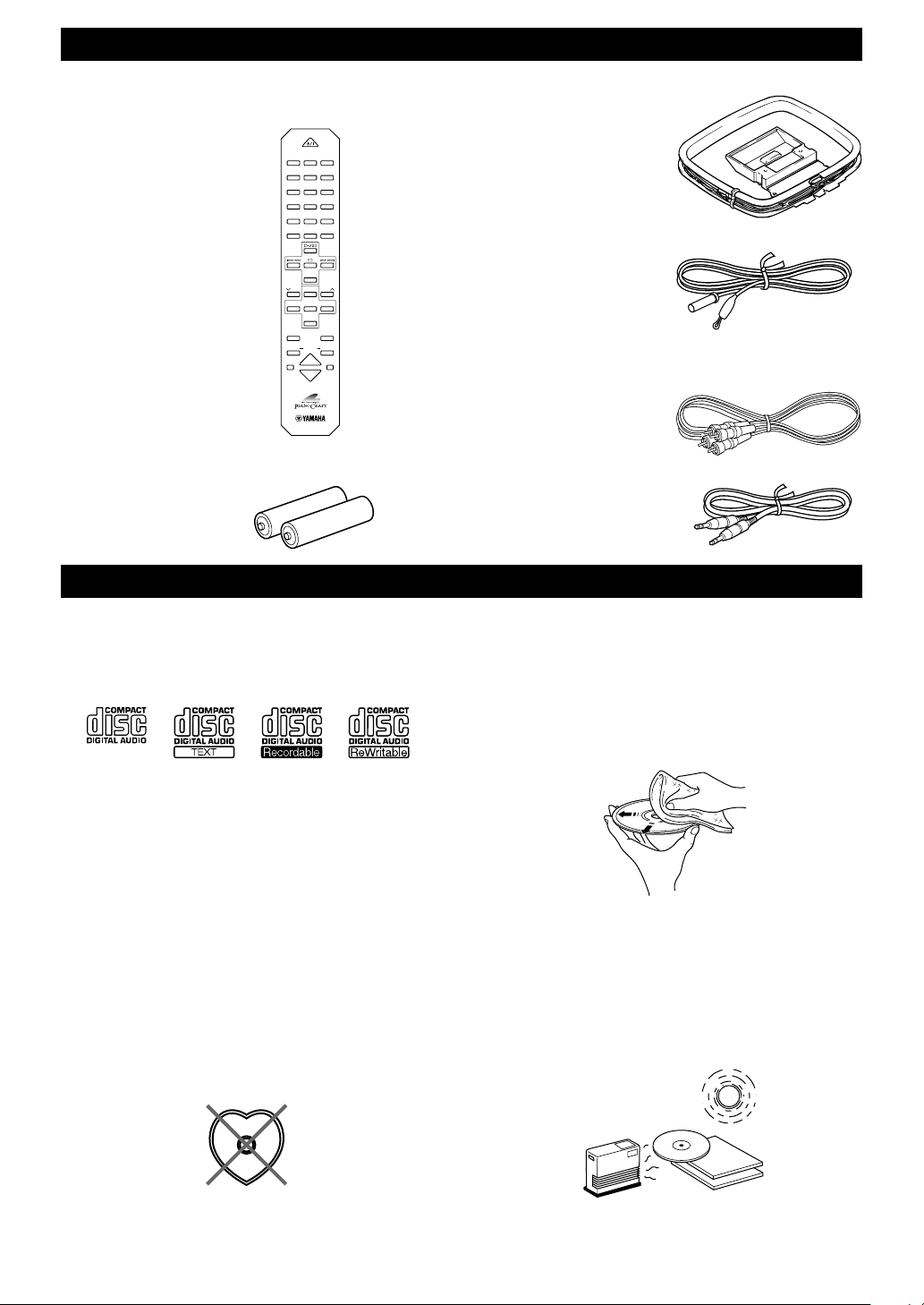
SUPPLIED ACCESSORIES
After unpacking, check that the following parts are contained.
<RX-E400>
• Remote control
POWER
1 2 3
123
4 5 6
456
7 8 9
78
0 +10 +100
FREQ/RDS MODE–PTY SEEK–START
REP
RANDOM
PROG
ABC
TEXT/TIME
R. TIME
DE
• AM loop antenna
TAPE
DIRECTION
PRESET
TUNER
PRESET
MD CD TAPE
AUX
MD
TAPE
/
PAUSE
/
PAUSE
REC
REC
DUBBING
MODE
START
SLEEP
DISPLAY
VOLUME
• Batteries (AA, R6, UM-3)
CD PREVENTIVE CARE
• This compact disc player is designed for use with
following types of disc only. Never attempt to load any
other type of disc into the unit. The unit will also play
8-cm (3-inch) compact discs.
(Playback only)
• Be sure to use only CD-R and CD-RW discs made by
reliable manufacturers.
• Some discs cannot be played depending on the disc
characteristics or recording conditions (copyrightprotected in a particular way, etc.).
• Compact discs are not subjected to wear during play,
but damage to the disc surface when the disc is being
handled can adversely affect the disc’s play.
• Do not use cleaning discs or warped discs. All of these
could damage the unit.
To prevent a malfunction of this unit
• Do not use any non standard shaped CD (heart, etc.)
available on the market, because it may damage the
unit.
• Indoor FM antenna
<CDX-E400>
• Audio pin cable
• System control cable
• Do not use a CD with tape, seals, or paste on it, because
damage to the unit may result.
• Compact discs are not affected by small particles of
dust or fingerprints on their playing surface, but even so
they should be kept clean. Wipe by using a clean, dry
cloth. Do not wipe with a circular motion; wipe straight
outward from the center.
• Do not try to clean the disc’s surface by using any type
of disc cleaner, record spray, antistatic spray or liquid,
or any other chemical-based liquid, because such
substances might irreparably damage the disc’s surface.
• Do not expose discs to direct sunlight, high temperature
or high humidity for a long period of time, because
these might warp or otherwise damage the disc.
No!
2
GETTING STARTED
Remote control
This remote control controls a whole system: not only
RX-E400 but also CDX-E400. Moreover, a cassette deck
(KX-E300) and MD recorder (MDX-E300) that level up
your system can be operated by it. Operating buttons for
each unit are explained on the pages below:
Receiver, RX-E400: p.8
CD player, CDX-E400: p.18
Cassette deck, KX-E300: p.23
MD recorder, MDX-E300: p.23
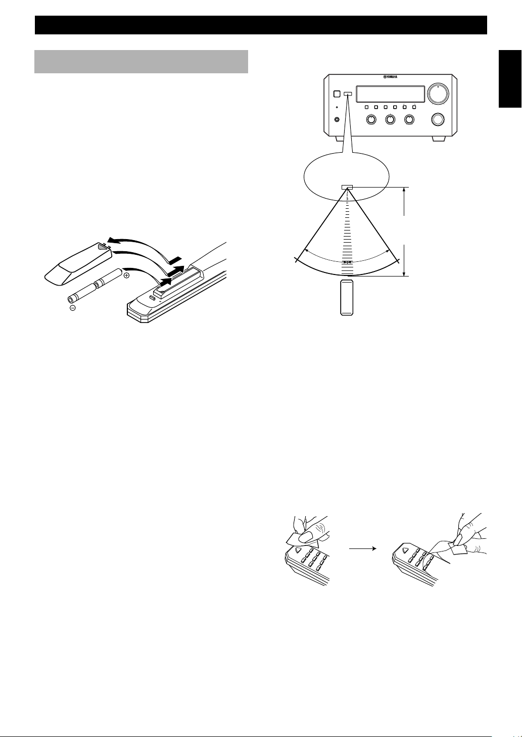
Battery installation
1
3
2
1 Remove the battery compartment cover.
2 Insert batteries into the battery compartment.
3 Replace the battery compartment cover.
Battery replacement
Remote control operation range
PRESET/TUNING
BALANCE
L
VOLUME
MIN MAX
INPUT
R
NATURAL SOUND
STEREO RECEIVER
AUTO/MAN'L
TIMER ADJ
TIMER HOUR MIN
TREBLEBASS
+–+–
RX–E400
PRESET/BAND
STANDBY/ON
DISPLAY MEMORY
TIMER
PHONES
Remote control
sensor
Within approximately
6 m (20 feet)
30°
30°
Notes
• There should be no large obstacles between the remote control
and the main unit.
• If the remote control sensor is directly illuminated by strong
lighting (especially an inverter type of fluorescent lamp, etc.),
it might cause the remote control not to work correctly. In this
case, reposition the main unit to avoid direct lighting.
English
If you find that the remote control must be used closer to
the main unit than usual, the batteries are weak. Replace
batteries with new ones.
Notes
• Use only AA, R6, UM-3 batteries for replacement.
• Be sure the polarities are correct. (See the illustration inside
the battery compartment.)
• Remove the batteries if the remote control will not be used for
an extended period of time.
• If batteries leak, dispose of them immediately. Avoid touching
the leaked material or letting it come in contact with clothing,
etc. Clean the battery compartment thoroughly before
installing new batteries.
Removing the protection sheet
The remote control is shipped with a protection sheet to
prevent the surface from being scratched during
transportation.
When removing the sheet, first put adhesive tape on an
edge of the remote control so that the tape sticks to the
sheet. Then peel the sheet off with the tape.
R
E
W
O
3
P
3
6
2
6
2
9
5
1
5
8
1
4
8
4
7
7
Note
• Do not scratch the remote control surface when peeling the
sheet off.
R
E
W
O
3
P
3
6
2
6
9
2
5
1
5
8
1
4
8
4
7
7
3
GETTING STARTED
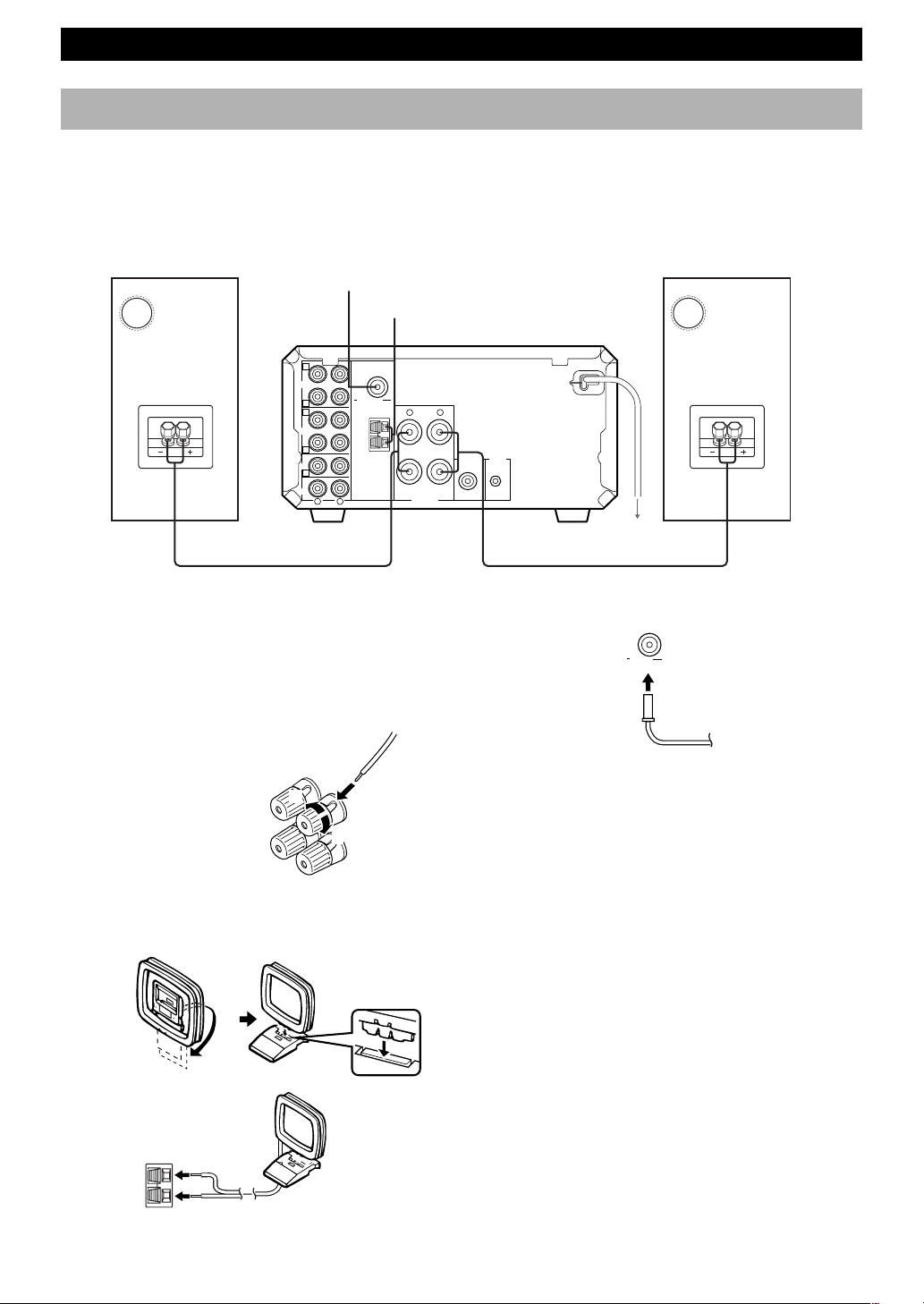
Connecting the speakers and antennas
Never plug the AC power cord to the wall outlet until all connections are
completed.
Follow the steps as shown below to connect the system using the supplied cords and accessories. Be sure all connections are
made correctly, that is to say L (left) to L, R (right) to R, “+” to “+” and “–” to “–”.
Right speaker
FM antenna
3
MD
OUT
TAPE
OUT
CD
AUX
C
IN
D
A
IN
B
IN
E
IN
R
L
1 Connect the Speakers.
1 Unscrew the knob.
2 Remove approx. 10 mm (4”) of insulation from
each of the speaker wires and insert the bare wire
into the terminal.
3 Tighten the knob to secure the wire.
Red: positive(+)
Black: negative(–)
2
1
2 AM loop antenna
FM ANT
75Ω UNBAL.
R L
GND
AM
ANT
6Ω MIN./SPEAKER
SPEAKERS
+
–
SUBWOOFER
1
Left speaker
SYSTEM
CONNECTOR
OUT
4 To wall outlet
3 Connect the FM Antenna.
FM ANT
75 Ω UNBAL
4 Connect the AC power cord to a wall outlet.
2 Connect the AM Antenna.
Set up the AM loop antenna, then connect it.
GND
AM
ANT
4
3
Notes
• Use external FM/AM antennas if you need better reception.
Consult your dealer.
• The AM loop antenna should be placed apart from the main
unit. The antenna may be hung on a wall.
To connect the subwoofer (optional)
You can reinforce the bass frequencies by adding a
subwoofer (optional).
Connect the SUBWOOFER OUT terminal of the unit to
the INPUT terminal of the subwoofer.
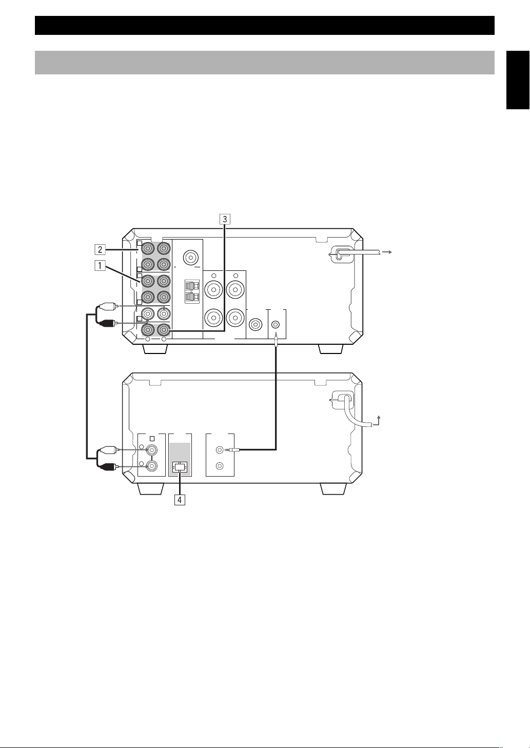
GETTING STARTED
Connecting the system
Connecting RX-E400 and CDX-E400
1 Connect ‰ to ‰ using the Audio pin cable.
Insert the plugs into the jacks of the same color.
2 Connect RX-E400 and CDX-E400 with the system control cable.
The other SYSTEM CONNECTOR of CDX-E400 is for connecting MDX-E300 or KX-E300.
3 Connect the AC power plug of CDX-E400 to AC OUTLET of RX-E400.
This connection allows you to control the power of the system through one-touch operation. It also reduces the standby
power consumption of CDX-E400.
C
MD
OUT
TAPE
OUT
CD
AUX
IN
D
A
IN
B
IN
E
IN
FM ANT
75Ω UNBAL.
GND
AM
ANT
R
L
R L
6Ω MIN./SPEAKER
SPEAKERS
+
–
SUBWOOFER
OUT
SYSTEM
CONNECTOR
<RX-E400>
To wall outlet
English
Audio pin cable
1
System control cable
DIGITAL
ANALOG
OPTICAL
E
OUT
L
R
OUT
SYSTEM
CONNECTOR
2
To RX-E400
<CDX-E400>
3
Adding KX-E300 and MDX-E300 to the above system
(For details, refer to the owner's manual supplied with the respective component.)
1 Connect Å and ı of RX-E400 to Å and ı of KX-E300.
2 Connect Ç and Î of RX-E400 to Ç and Î of MDX-E300.
3 Connect an external component to the AUX terminal of RX-E400.
4 Connect DIGITAL OPTICAL OUT of CDX-E400 to DIGITAL OPTICAL IN of MDX-E300.
Take off the covers of the optical fiber cable plug, the DIGITAL OPTICAL OUT jack, and the DIGITAL OPTICAL
IN jack before making digital connections. Be sure to replace the terminal’s cover when the terminal on the rear panel
is not being used, in order to protect from dust.
Caution
• Never turn RX-E400 on until all connections between components have been completed.
• Never connect or disconnect the system control cable and/or power cord while the system components are turned on.
5
GETTING STARTED
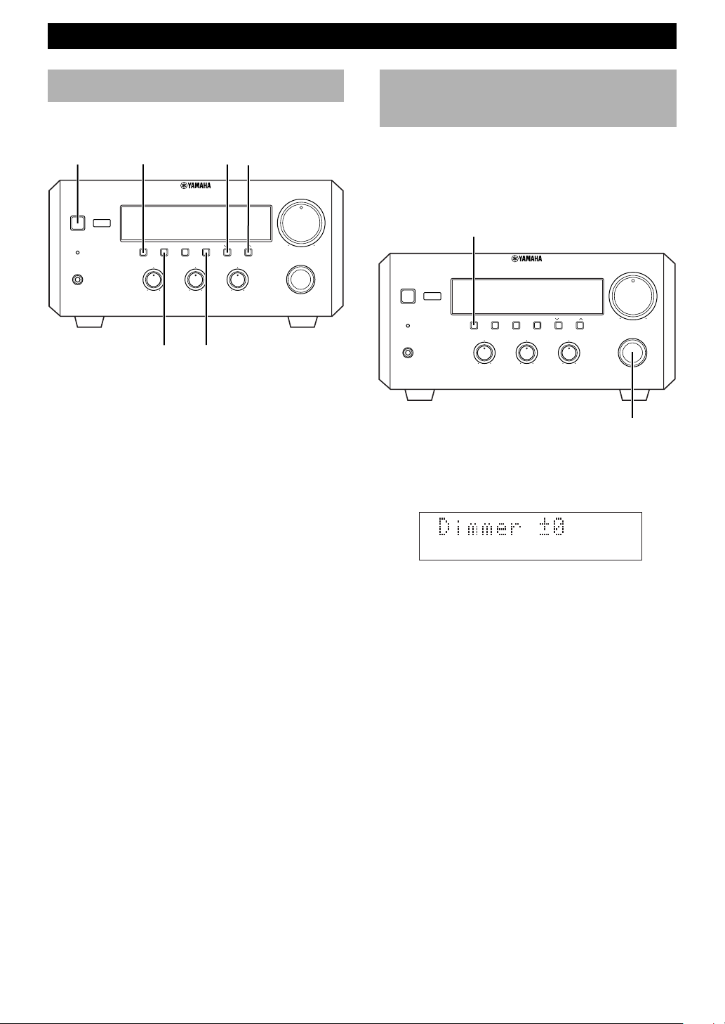
Setting the clock
You must set the clock before you use the timer functions.
The clock is based on a 24-hour system.
STANDBY/ON
STANDBY/ON
TIMER
PHONES
DISPLAY
NATURAL SOUND
DISPLAY MEMORY
TIMER ADJ
+– +–
HOUR
STEREO RECEIVER
RX–E400
AUTO/MAN'L
PRESET/BAND
TIMER HOUR MIN
TREBLEBASS
PRESET/BANDTIME ADJ
PRESET/TUNING
BALANCE
L
MIN
VOLUME
MIN MAX
INPUT
R
1 Turn on the power by pressing STANDBY/ON on
the front panel, or POWER on the remote control.
2 While the power is on, press DISPLAY to display
the time.
3 While holding TIME ADJ, press HOUR to set the
hour.
• If you want to move the time in the reverse
direction, press HOUR while holding TIME ADJ
and PRESET/BAND.
Adjusting the brightness
of the display
You can adjust the brightness of the display. If you have
connected the CD player (CDX-E400), cassette deck
(KX-E300), and/or MD recorder (MDX-E300) to this
unit, the brightness of the displays is automatically
adjusted to that of this unit.
DISPLAY
NATURAL SOUND
STEREO RECEIVER
TREBLEBASS
PRESET/BAND
RX–E400
PRESET/TUNING
BALANCE
L
R
STANDBY/ON
TIMER
PHONES
DISPLAY MEMORY
AUTO/MAN'L
TIMER ADJ
TIMER HOUR MIN
+– +–
Press and hold DISPLAY for about two seconds so that
“Dimmer ±0” appears on the display. While holding
DISPLAY, turn INPUT clockwise to increase or
counterclockwise to decrease brightness.
VOLUME
MIN MAX
INPUT
INPUT
4 While holding TIME ADJ, press MIN to set the
minutes.
• If you want to move the time in the reverse
direction, press MIN while holding TIME ADJ
and PRESET/BAND.
To display the clock
Press DISPLAY.
The current time appears for about 8 seconds, then the
normal display returns. Some buttons and controls may
not work while the current time is displayed.
Note
• In the event of a power failure or when the AC power cord is
disconnected for more than five minutes, you must reset the
clock.
Control Range: ±0 to –6 (Preset value: ±0)
6
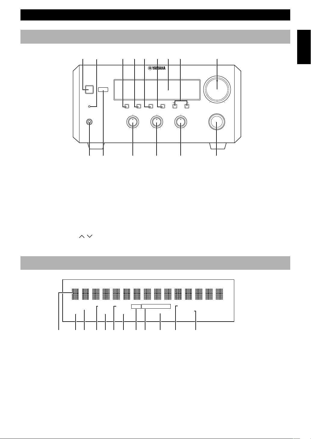
RX-E400 NAMES OF BUTTONS AND CONTROLS
12 345678 9
STANDBY/ON
TIMER
PHONES
0 q wer t
1 STANDBY/ON (P.9)
2 TIMER indicator (P.15)
3 DISPLAY (P.15)
4 TIME ADJ/MEMORY (P.6/P.11)
5 AUTO/MAN’L/TIMER (P.10/P.15)
6 PRESET/BAND (P.10)
7 Display (P.7)
8 PRESET/TUNING / (P.10)
HOUR/MIN (P.6/P.15)
Front panel
NATURAL SOUND
DISPLAY MEMORY
STEREO RECEIVER
AUTO/MAN'L
TIMER ADJ
TIMER HOUR MIN
TREBLEBASS
+– +–
PRESET/BAND
9 VOLUME (P.9)
0 PHONES (P.9)
q Remote control sensor (P.3)
w BASS (P.9)
e TREBLE (P.9)
r BALANCE (P.9)
t INPUT (P.9)
RX–E400
PRESET/TUNING
BALANCE
L
English
VOLUME
MIN MAX
INPUT
R
PRESET
EDIT
1345267890qw
1 Multi-information display
2 EDIT indicator
3 PRESET indicator (P.11)
4 STEREO indicator (P.10)
5 TUNED indicator (P.10)
6 AUTO indicator (P.10)
Display
STEREO AUTO RDS PS RT CTPTY
TUNED PTY HOLD
MEMORY
7 MEMORY indicator (P.11)
8 RDS indicator (P.12)
9 RDS mode indicators (P.12)
0 PTY HOLD indicator (P.13)
q TIMER indicator (P.15)
w SLEEP indicator (P.16)
TIMER
SLEEP
7
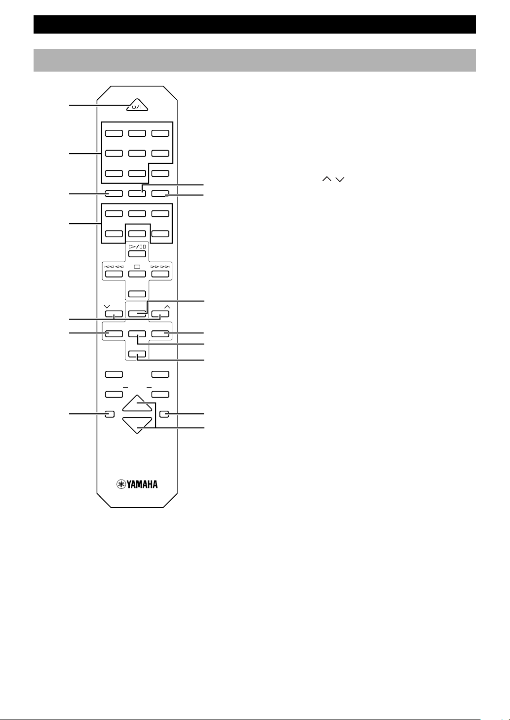
RX-E400 NAMES OF BUTTONS AND CONTROLS
Remote control
1
2
3
6
7
9
POWER
1 2 3
123
4 5 6
456
7 8 9
78
0 +10 +100
FREQ/RDS MODE–PTY SEEK–START
REP
RANDOM
PROG
ABC
TEXT/TIME
R. TIME
DE
TAPE
DIRECTION
PRESET
TUNER
PRESET
MD CD TAPE
AUX
REC
MD
/
PAUSE
REC
TAPE
/
PAUSE
4
5
8
0
q
w
1 POWER (P.9)
2 Preset numbers (P.11)
3 FREQ/RDS (P.12)
4 PTY SEEK MODE (P.13/P.14)
5 PTY SEEK START (P.13/P.14)
6 A/B/C/D/E (P.11)
7 PRESET / (P.11)
8 TUNER (RX-E400) (P.11)
9 MD (MDX-E300) (P.23)
0 TAPE (KX-E300) (P.23)
q CD (CDX-E400) (P.19)
w AUX (The equipment connected to the AUX
terminal) (P.5)
e SLEEP (P.16)
r DISPLAY (P.15)
t VOLUME %/fi (P.9)
Note
• 8~w are operation buttons and input selectors for each
component.
e
MODE
SLEEP
DUBBING
VOLUME
START
DISPLAY
r
t
8
 Loading...