

Yamaha CDXE-100 Service manual
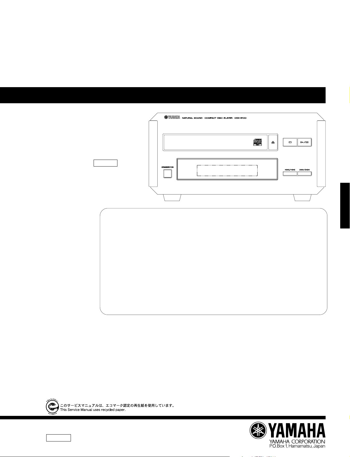
CDX-E100
MINI COMPONENT SYSTEM CRX-E100
CDX-E100
SERVICE MANUAL
CRX-E100 is composed of RX-E100 and
CDX-E100. This is a service manual for
the CDX-E100.
For service manuals of RX-E100, please
refer to the service manuals with the
following publication numbers :
RX-E100 100684
For the system operation, please refer
to Service Manual for the RX-E100.
This manual has been provided for the use of authorized YAMAHA Retailers and their service personnel.
It has been assumed that basic service procedures inherant to the industry, and more specifically YAMAHA Products, are already
known and understood by the users, and have therefore not been restated.
WARNING: Failure to follow appropriate service and safety procedures when servicing this product may result in personal
IMPORTANT: The presentation or sale of this manual to any individual or firm does not constitute authorization, certification or
The data provided is believed to be accurate and applicable to the unit(s) indicated on the cover. The research, engineering, and
service departments of YAMAHA are continually striving to improve YAMAHA products. Modifications are, therefore, inevitable
and specifications are subject to change without notice or obligation to retrofit. Should any discrepancy appear to exist, please contact
the distributor's Service Division.
WARNING: Static discharges can destroy expensive components. Discharge any static electricity your body may have accumu-
IMPORTANT: Turn the unit OFF during disassembly and parts replacement. Recheck all work before you apply power to the unit.
■ CONTENTS
IMPORTANT NOTICE
injury, destruction of expensive components and failure of the product to perform as specified. For these reasons,
we advise all YAMAHA product owners that all service required should be performed by an authorized
YAMAHA Retailer or the appointed service representative.
recognition of any applicable technical capabilities, or establish a principle-agent relationship of any form.
lated by grounding yourself to the ground buss in the unit (heavy gauge black wires connect to this buss).
CDX-E100
TO SERVICE PERSONNEL.....................................1~2
REAR PANELS............................................................. 3
SPECIFICATIONS.........................................................3
INTERNAL VIEW ..........................................................4
DISASSEMBLY PROCEDURES ..............................4~5
STANDARD OPERATION CHART..........................6~7
TEST MODE..............................................................8~9
ERROR MESSAGE ...............................................10~11
100685
IC DATA ................................................................12~16
DISPLAY DATA ..........................................................17
IC BLOCK .............................................................18~19
PIN CONNECTION DIAGRAM...................................19
BLOCK DIAGRAM ................................................20~21
PRINTED CIRCUIT BOARD ................................22~27
SCHEMATIC DIAGRAM............................................. 28
PARTS LIST..........................................................29~37

CDX-E100
■ TO SERVICE PERSONNEL
1. Critical Components Information.
Components having special characteristics are marked Z
and must be replaced with parts having specifications equal
to those originally installed.
2. Leakage Current Measurement (For 120V Models Only).
When service has been completed, it is imperative to verify
that all exposed conductive surfaces are properly insulated
from supply circuits.
● Meter impedance should be equivalent to 1500 ohm shunted
by 0.15µF.
● Leakage current must not exceed 0.5mA.
● Be sure to test for leakage with the AC plug in both
polarities.
WALL
OUTLET
EQUIPMENT
UNDER TEST
INSULATING
TABLE
CAUTION: USE OF CONTROLS OR ADJUSTMENTS OR PERFORMANCE OF PROCEDURES OTHER THAN THOSE
SPECIFIED HEREIN MAY RESULT IN HAZARDOUS RADIATION EXPOSURE.
THE COMPACT DISC PLAYER SHOULD NOT BE ADJUSTED OR REPAIRED BY ANYONE EXCEPT PROPERLY
QUALIFIED SERVICE PERSONNEL.
PROTECTION OF EYES FROM LASER BEAM DURING SERVICING
This set employs a laser. Therefore, be sure to carefully
follow the instructions below when servicing .
CDX-E100
1. Laser Diode Properties
● Material : GaAlAs
● Wavelength : 780 nm
● Emission Duration : Continuous
● Laser Output : max. 44.6 µW*
* This output is the value measured at a distance of
about 200 mm from the objective lens surface on
the Optical Pick-up Block.
2. When checking the laser diode emission, keep your
eyes more than 30 cm away from the objective lens.
AC LEAKAGE
TESTER OR
EQUIVALENT
WARNING: CHEMICAL CONTENT NOTICE!
The solder used in the production of this product contains LEAD. In addition, other electrical/electronic
and/or plastic (where applicable) components may also contain traces of chemicals found by the
California Health and Welfare Agency (and possibly other entities) to cause cancer and/or birth defects
or other reproductive harm.
DO NOT PLACE SOLDER, ELECTRICAL/ELECTRONIC OR PLASTIC COMPONENTS IN YOUR MOUTH
FOR ANY REASON WHATSOEVER!
Avoid prolonged, unprotected contact between solder and your skin! When soldering, do not inhale
solder fumes or expose eyes to solder/flux vapor!
If you come in contact with solder or components located inside the enclosure of this product, wash your
hands before handling food.
1
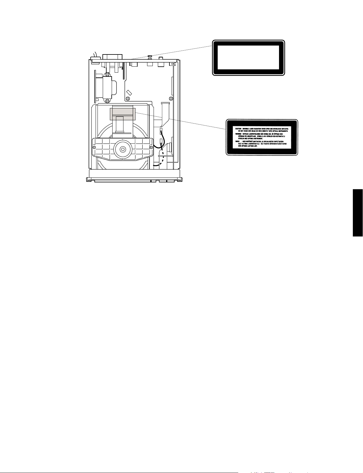
➀ R, B, G models
CLASS 1 LASER PRODUCT
➁ R, B, G models
CDX-E100
English
THIS PRINTING (SEE POSITION SHOWN IN THE ILLUSTRATION) INFORMS THE USER THAT THE APPARATUS
➀
CONTAINS A LASER COMPONENT.
➁ THIS LABEL (SEE POSITION SHOWN IN THE ILLUSTRATION) WARNS THAT ANY FURTHER PROCEDURE WILL
BRING THE USER INTO EXPOSURE WITH THE LASER BEAM.
CAUTION : USE OF CONTROLS, ADJUSTMENTS OR PERFORMANCE OF PROCEDURES OTHER THAN THOSE
SPECIFIED HEREIN, MAY RESULT IN HAZARDOUS RADIATION EXPOSURE.
Swedish
DENNA MÄRKNING (SE FIGUR) UPPLYSER OM ATT DET I APPARATEN INGÅR EN LASERKOMPONENT AV TYP
➀
KLASS 1.
➁ VARNINGSMÄRKNING (SE FIGUR) FÖR STRÅLNING. INGREPP I APPARATEN BÖR ENDAST FÖRETAGAS AV
FACKMAN MED KÅNNEDOM OM LASER. APPARATEN INNEHÄLLER EN LASERKOMPONENT SOM AVGER
STRÅLNING ÖVERSTIGANDE GRÄNSEN FÖR LASERKLASS 1.
VARNING : OSYNLIG LASERSTRÅLNING NÄR DENNA DEL ÄR ÖPPNAD: BETRAKTA EJ STRÅLEN.
Danish
DETTE MÆRKAT ER ANBRAGT SOM VIST I ILLUSTRATIONEN FOR AT ADVARE BRUGEREN OM AT AP-
➀
PARATET INDEHOLDER EN LASERKOMPONENT.
CDX-E100
➁ DETTE MÆRKAT OM LASEREN ER ANBRAGT PÅ APPARATET SOM EN OPLYSNING OM AT APPARATET
INDEHOLDER ET LASERKOMPONENT.
ADVARSEL : INDGREB BOR KUN FORETAGES AF EN FAGMAND DA DER ER RISIKO FOR RADIOAKTIV
STRÅLING.
ADVARSEL : USYNLIG LASERSTRÅLING VED ÅBNING.
UNDGÅ UDSAETTELSE FOR STRÅLING.
Finnish
VARO! :
AVATTAESSA OLET ALTTIINA NÄKYMÄTTÖMÄLLE LASERSÄTEILYLLE. ÄLÄ KATSO SÄTEESEEN.
2
CDX-E100
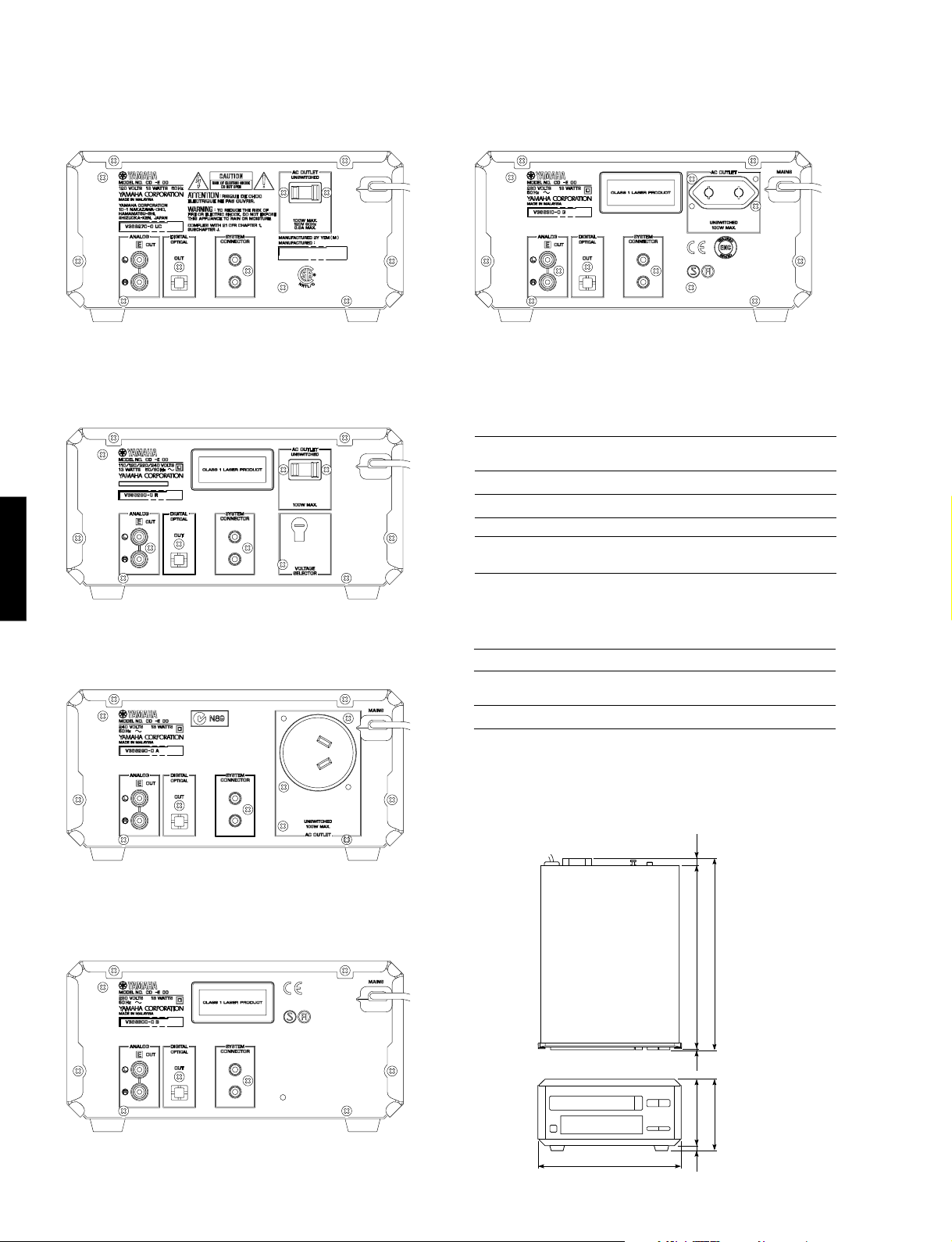
217(8-9/16")
100(3-15/16")
8
(5/16")
108(4-1/4")
3
(1/8")
12
(1/2")
275(10-13/16")
290(11-7/16")
■ REAR PANELS
▼ U, C models
▼ R model
CDX-E100
▼ A model
▼ G model
■ SPECIFICATIONS
Output Level
1kHz, 0dB 2.0 ± 0.5Vrms
Signal to Nosie Ratio (EIAJ) 102dB
Dynamic Range 95dB
240V
Harmonic Distortion+Noise (1kHz) 0.004%
Frequency Response
2Hz — 20kHz ±0.5dB
Power Requirements
U, C models 120V AC 60Hz
B, G models 230V AC 50Hz
A model 240V AC 50Hz
R model 110/120/220/240V AC 50/60Hz
Power Consumption 13W
Dimensions (W x H x D) 217 x 108 x 290mm
(8-9/16" x 4-1/4" x 11-7/16")
Weight 3.0kg (6 lbs 9 oz)
*Specifications are subject to change without notice.
▼ B model
3
U ................... U. S. A. model
C ................Canadian model
A .............. Australian model
● DIMENSION
B .................... British model
G ............... European model
R .................. General model
Unit : mm (inch)
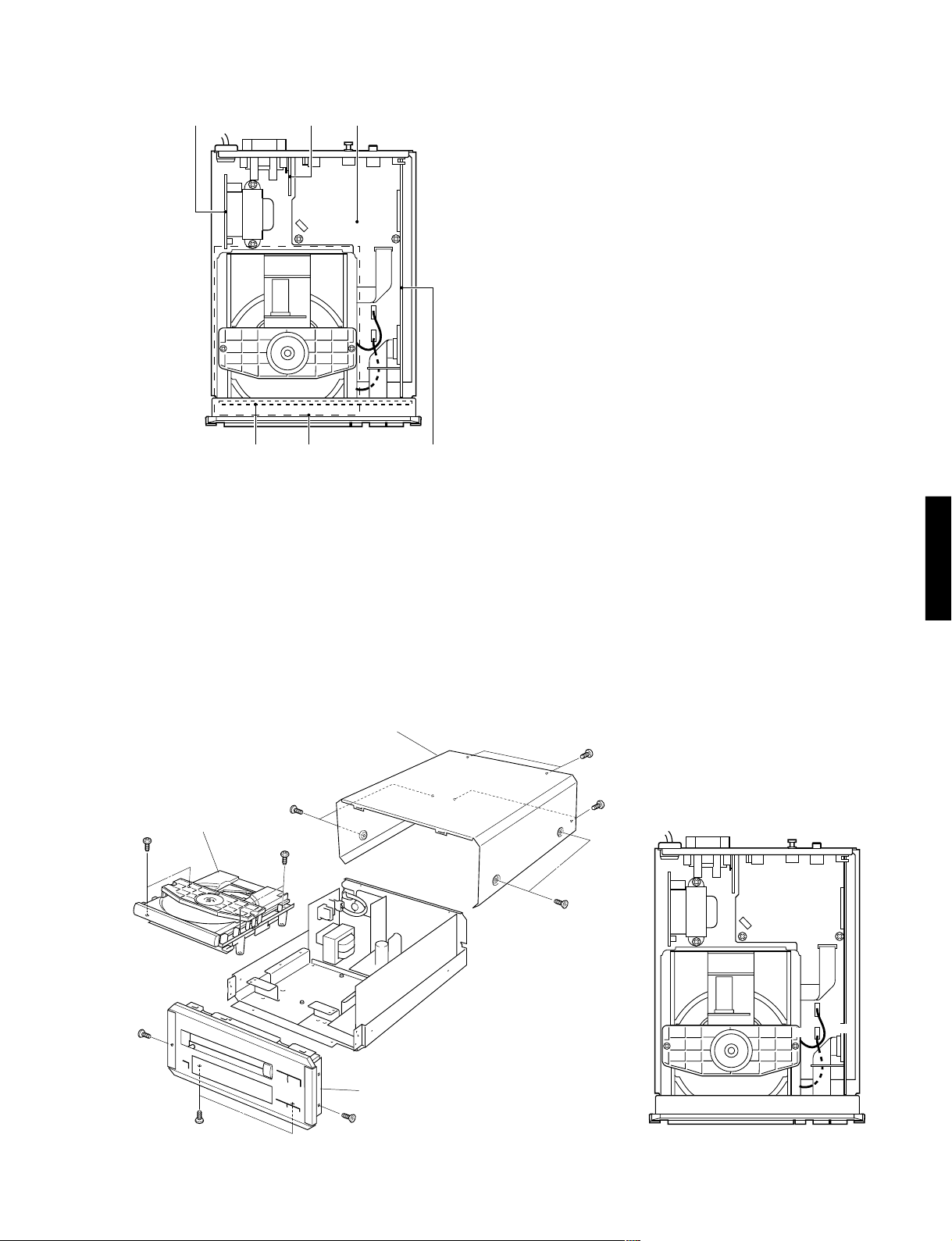
■ INTERNAL VIEW
CDX-E100
q w e
q P.C.B. MAIN (3)
w P.C.B. MAIN (4)
e P.C.B. MAIN (2)
r P.C.B. MAIN (5)
t CD MECHANISM UNIT
y P.C.B. MAIN (1)
tr
y
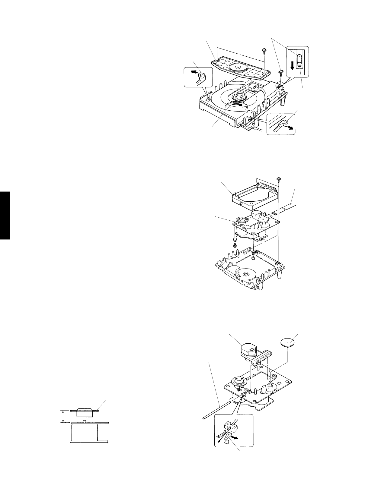
■ DISASSEMBLY PROCEDURES (Remove parts in disassembly order as numbered.)
1. Removal of Top Cover
a. Remove 4 screws ( q
) and 4 screws
b. Lift the Top Cover at the rear and move it rear-ward slantingly.
2. Removal of Front Panel
a. Remove a connector (CB6) in Fig. 2.
b. Remove 2 ( e ) screws and 2 screws
c.
Remove 2 hooks and then pull the Front Panel forward.
3. Removal of CD Mechanism Unit
a. Remove 3 connectors (CB1, CB2, CB3) in Fig. 2.
b. Remove 4 screws ( t ) in Fig. 1.
( w )
( r )
in Fig. 1.
in Fig. 1.
CDX-E100
t
e
CD Mechanism
Unit
r
Top Cover
q
t
Front Panel
e
Fig. 1
w
w
q
CB1
CB2
CB6
CB3
Fig. 2
4
CDX-E100
4. Removal of Tray Unit
a. Remove 2 screws ( y ) and then remove the Chuck-
ing Unit in Fig. 3.
b. Remove 1 hook and then remove the Stopper Pin in
Fig. 3.
c. Rotate the Drive Gear and then open the Tray Unit in
Fig. 3.
d. Detach the Stoppers on both sides and then pull out
the Tray in Fig. 3.
5. Removal of Pick-up Head
a. Remove 2 screws ( u ) in Fig. 4.
b. Remove a pick-up cable in Fig. 4.
c. Remove 4 screws ( i
) and then remove the Drive
Unit in Fig. 4.
d. Remove the gear A in Fig. 5.
e. Pull out the Sled Shaft in Fig. 5.
f. Remove the Pick-up Head.
Chucking Unit
Stopper
Drive Gear
Sub Chassis (S)
Drive Unit
Stopper Pin
y
Hook
Stopper
Fig. 3
u
Pick-up Cable
CDX-E100
Check that the disc table height is as specified below.
i
i
Fig. 4
Pick-up Head Gear A
Sled Shaft
Disc Table
19.4 ± 0.2mm
Stopper
5
Fig. 5
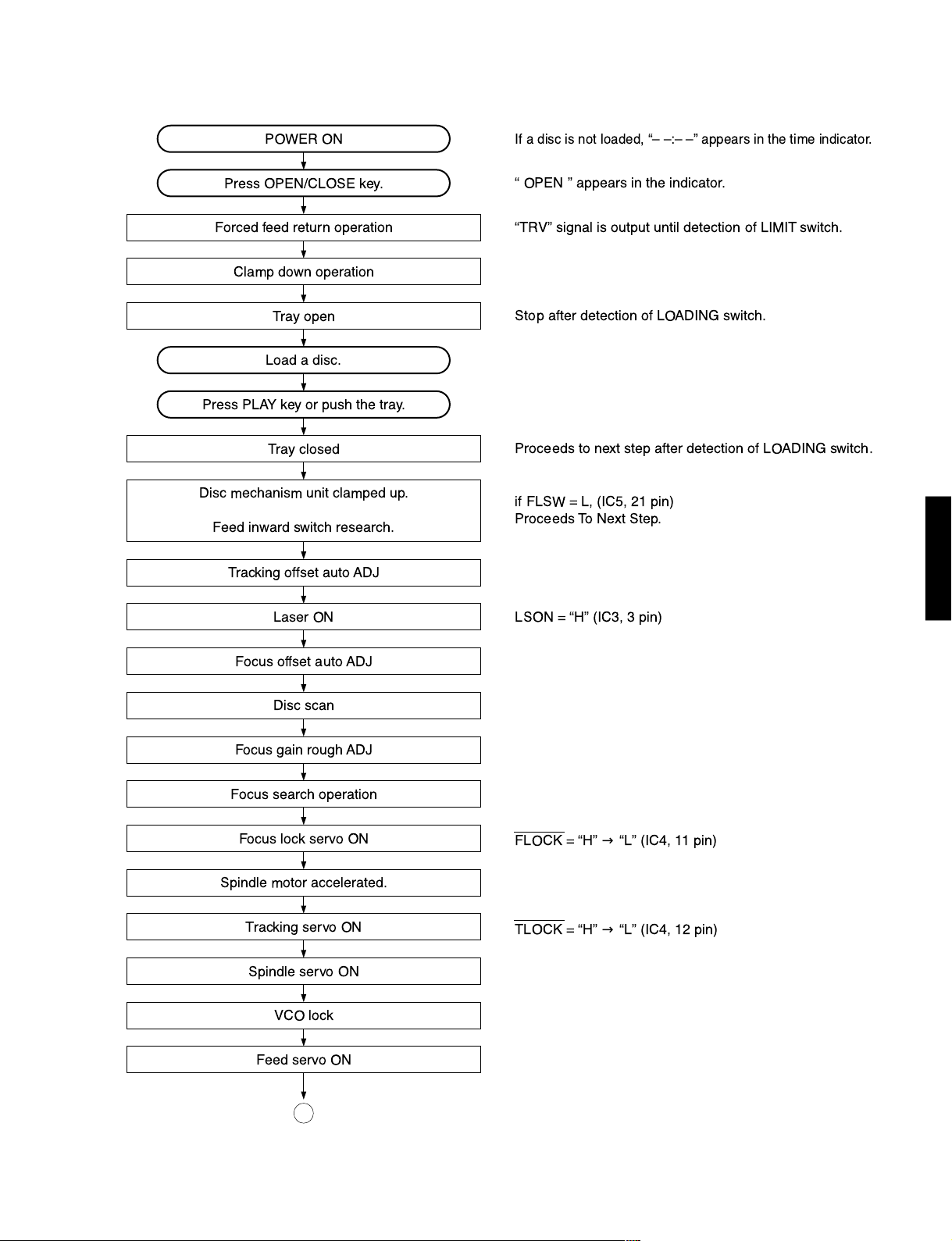
■ STANDARD OPERATION CHART
Press OPEN/CLOSE key.
Forced feed return operation
Clamp down operation
Tray open
Tracking offset auto ADJ
Focus offset auto ADJ
Load a disc.
Press PLAY key or push the tray.
Tray closed
Disc mechanism unit clamped up.
Feed inward switch research.
Laser ON
Disc scan
Focus gain rough ADJ
Focus search operation
Focus lock servo ON
Spindle motor accelerated.
Tracking servo ON
Spindle servo ON
Feed servo ON
Ò OPEN Ó appears in the indicator.
ÒTRVÓ signal is output until detection of LIMIT switch.
Stop after detection of LOADING switch.
Proceeds to next step after detection of LOADING switch.
if FLSW = L, (IC5, 21 pin)
Proceeds To Next Step.
LSON = ÒHÓ (IC3, 3 pin)
FLOCK = ÒHÓ→ÒLÓ (IC4, 11 pin)
TLOCK = ÒHÓ→ÒLÓ (IC4, 12 pin)
POWER ON
If a disc is not loaded, ÒÐ Ð:Ð ÐÓ appears in the time indicator.
VCO lock
CDX-E100
CDX-E100
A
6
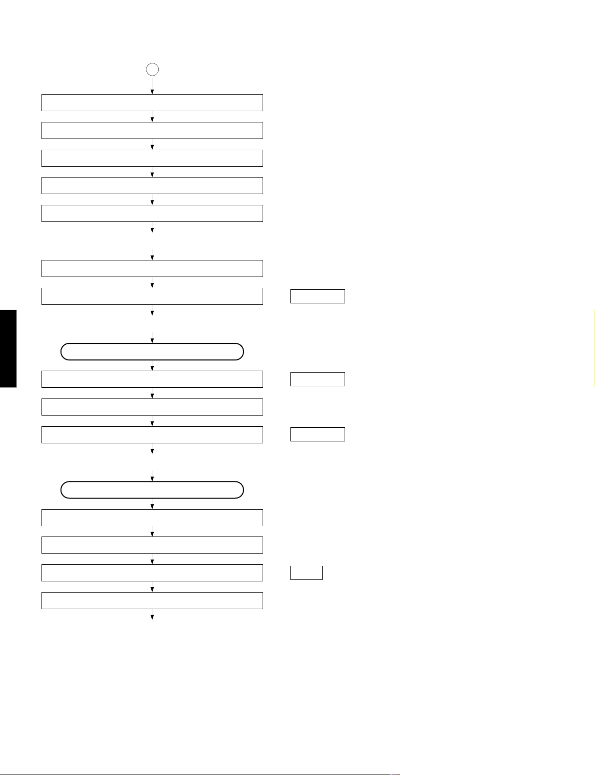
CDX-E100
A
Tracking gain rough ADJ
Tracking balance ADJ (only tray OPEN/CLOSE)
Focus balance ADJ
Focus gain ADJ
Tracking gain ADJ
* TOC READ
After searching the beginning, MUTE is cancelled.
CDX-E100
After searching the beginning, MUTE is cancelled.
~ * Data fetch cycle ~
TRACK NO. “1” is searched.
~ PLAY ~
Set to SEARCH by means of Y, T key.
MUTE ON
TRACK search
~ PLAY ~
Press the STOP key.
MUTE ON
: MUTE OFF = “H” → “L” (Q4 Collector)
“0:00” appears in the time indicator.
: MUTE OFF = “L” → “H”
: MUTE OFF = “H” → “L”
“0:00” appears in the time indicator.
Spindle motor stop
Laser OFF
Forced feed return
~ STOP ~
7
: LSON = “H” → “L” (IC3, 3 pin)
CDX-E100
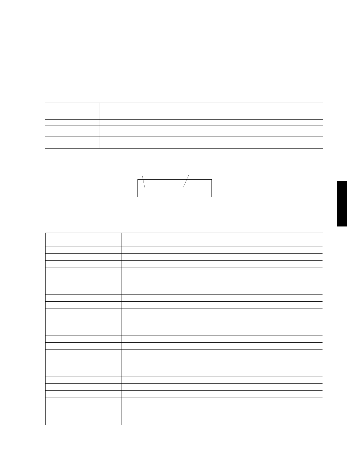
■ TEST MODE
Turning ON the POWER while pressing the keys “STOP” and “PLAY/PAUSE” will set to the TEST mode. (When
the TEST mode is set, all indicators light for 1 second.)
Note: When the power off, “STOP” key must be pressed before “PLAY/PAUSE” key pressd. Otherwise “PLAY/
PAUSE” key operation causes the product mode.
● Test Mode Function List of Panel keys
PANEL KEY
OPEN/CLOSE
PLAY/PAUSE
STOP
TT
EE
T/
E
TT
RR
R/
RR
EE
YY
Y
YY
(SKIP/SEARCH)
(SKIP/SEARCH)
Sample of display of test command
Execute the test command selected with the SKIP/SEARCH keys
Plays if focus servo is effective. TRON, MUTE OFF.
All stop. (Focus, spindle, feed, laser, tray, etc.) Initializes FL display
Increment the test command number.
Decrement the test command number.
FUNCTION
Command No.
Command Name
02:AutoAdj 2
The functions corresponded to the test command numbers are as follows.
Command
No.
00
01
02
03
04
05
06
07
08
09
10
11
12
13
14
15
16
17
18
19
20
21
22
23
24
25
Command
Name
Op/Cl
AutoAdj 1
AutoAdj 2
AutoAdj 3
TV Rev
TV Fwd
TV Stop
SP Accel
SP Brake
SP SV.On
SP SV.Off
SP Stop
FO Search
TR,TV Off
1Kick Rev
1Kick Fwd
10 K. Rev
10 K. Fwd
30 K. Rev
30 K. Fwd
150K. Rev
150K. Fwd
PrdctMode
Error Msg
Test Eep
Check FL
FUNCTION
Tray open/close.
Auto adjustment mode 1 (TR-off set, FO-off set, FO-rough gain adjustment)
Auto adjustment mode 2 (TR-balance, TR-rough gain adjustment)
Auto adjustment mode 3 (FO-fine gain, TR-fine gain, FO-balance adjustment)
Move traverse reverse till the inner SW turn on.
Move traverse forward.
Stop traverse.
Accelerate spindle.
Decelerate spindle.
Spindle servo on.
Spindle free (servo off)
Stop spindle.
FOON, TROF (Enter focus search if focus servo is off.)
FOON, TROF, TVOF(FEOF) (Enter focus search if focus servo is off.)
Reverse 1 track kick continuously.
Forward 1 track kick continuously.
Reverse 10 tracks kick continuously.
Forward 10 tracks kick continuously.
Reverse 30 tracks kick continuously.
Forward 30 tracks kick continuously.
Reverse 150 tracks kick continuously.
Forward 150 tracks kick continuously.
Returns to product mode.
Display the latest error message. (see page 10)
Check EEPROM. (Mute on if test OK. Mute off if test NG)
Check FL display. (see page 9)
CDX-E100
8
CDX-E100
Test mode function List of Remote Controller keys
System Control
Code
80
81
83
84
85
86
87
88
89
8A
8B
8C
8D
90
91
92
93
94
95
96
97
98
99
9A
CDX-E100
KEY
STOP
PLAY/PAUSE
YY
Y SKIP
YY
TT
T SKIP
TT
RR
R SEARCH
RR
EE
E SEARCH
EE
SEARCH END
RANDOM
TEXT/TIME
PROG
REPEAT
TAPE
PEAK
0
1
2
3
4
5
6
7
8
9
+10
FUNCTION
All stop. (Focus, spindle, traverse, laser, tray, etc.)
PLAY (FOON, TRON, TVON(FEON), SPON)
Move traverse forward.
Move traverse reverse till the inner SW turn on.
Forward 10 track kick continuously.
Reverse 10 track kick continuously.
–
SPON (Spindle servo on.)
Check FL display.
Accelerate spindle.
FOON, TROF (Enter focus search if focus servo is off.)
Spindle free (servo off)
–
Forward 150 tracks kick continuously. (Coefficient set up mode : lower digit up)
Returns to product mode.
Auto adjustment mode 1 (TR-off set, FO-off set, FO-rough gain adjustment)
Auto adjustment mode 2 (TR-balance, TR-rough gain adjustment)
Auto adjustment mode 3 (FO-fine gain, TR-fine gain, FO-balance adjustment)
Reverse 1 track kick continuously. (Coefficient set up mode : address down)
Forward 1 track kick continuously. (Coefficient set up mode : address up)
Reverse 30 tracks kick continuously. (Coefficient set up mode : upper digit down)
Forward 30 tracks kick continuously. (Coefficient set up mode : upper digit up)
Reverse 150 tracks kick continuously.(Coefficient set up mode : lower digit down)
Change the coefficient mode.
(^Conefficient set up mode^ Return to product mode with set up coefficient)
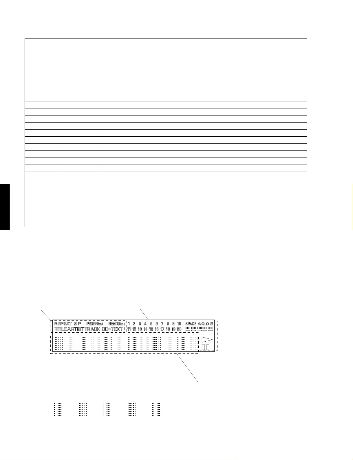
Note : Check FL display
Each time the key pressed, the display changes as follows (q^w^................^o)
q Illuminate all indicators in this part.
w Illuminate all indicators in this part.
e ~ u Each dot matrix changes as follows. i Dot matrix illuminates like this.
erty u
o All indicators go out.
9
CDX-E100
■ ERROR MESSAGE
(1) If stopped by any cause, error message can be displayed by pressing the remote STOP key while pressing and
holding the panel STOP key, or by test mode command number 23.
The player holds the latest error message in EEPROM. So even if stopped with no error, the latest error message
can be displayed with same operation.
(2) Shown below is an example of display. (“E-73” as an example)
1 E-73
(3) Listed in the table below are error messages.
● Error Messages List
ERROR MESSAGES
E – X0
E – X1
E – 71
E – 72
E – 73
E – 75
Data cannot be read after finishing search.
Data cannot be read during PLAY(X=0), PAUSE(X=3), or SCAN(X=2).
At the start, tracking servo is not effective.
At the start, spindle servo PLL is not effective.
At the start, data can not read.
Tracking servo off in FO balance, or FO fine, or TR fine gain adjustment
DESCRIPTION
and recovery action failure.
E – 94
E – 95
E – X7
E – X8
ERROR
Close switch does not work with tray closed.
Open switch does not work with tray open.
Traverse(Feed) inner switch does not work.
Recovery action fails after focus drop.
MN35511 does not give response of SENSE, with resetting by the unit’s
microcomputer.
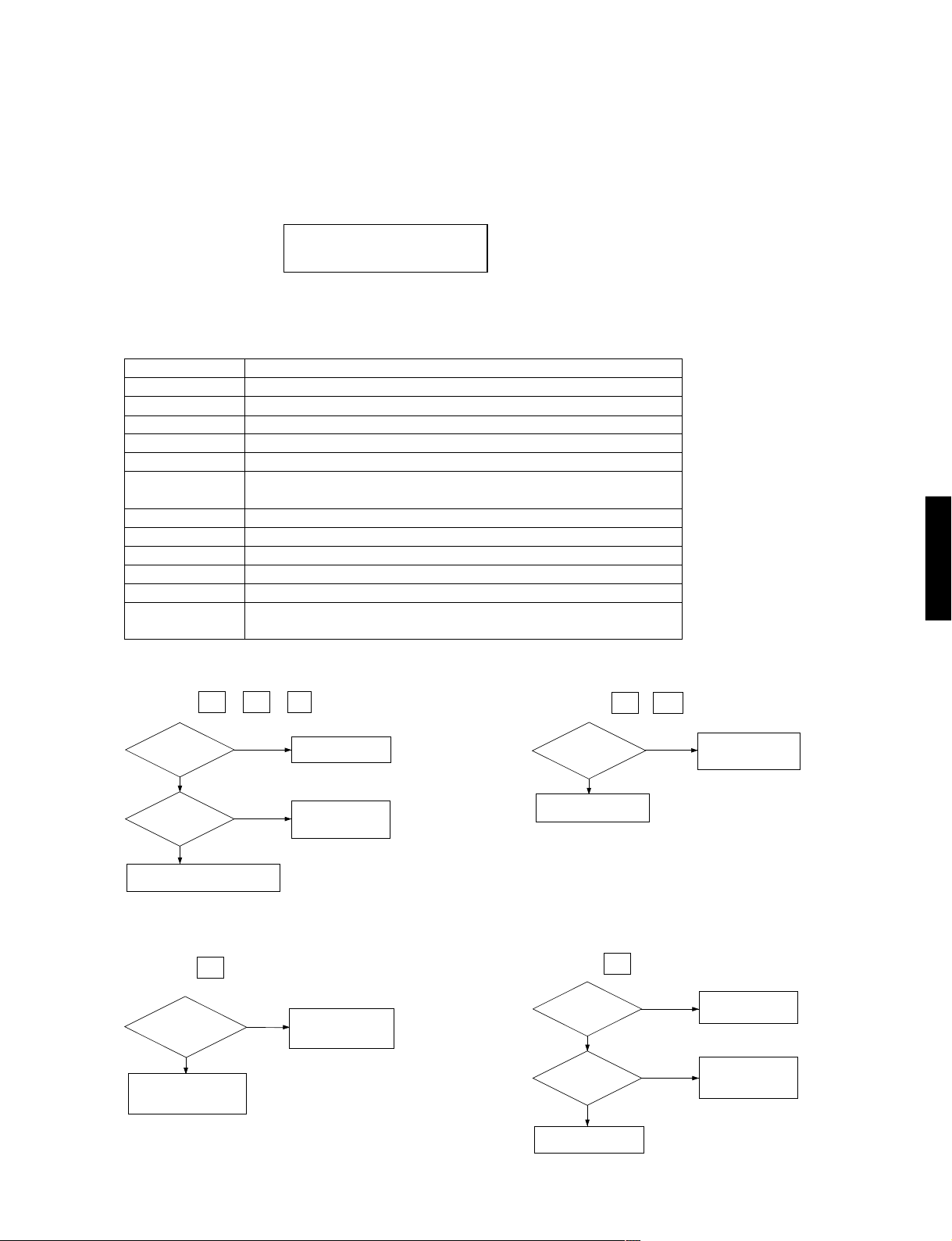
1) Error Code Troubleshooting
Error code X0 , X1 , 73 ...... Data cannot be read.
Is disc dirty or
scratched?
NO
Pick-up position
Within disc range
Pick-up defective, Spindle system
defective (Motor fails to run, etc.)
YES
Outermost
(on mirror
surface)
Check by using
another disc.
TRACKING
servo defective.
FEED servo defective.
*No. for each state
(meaning of “X”)
PLAY X=“0”
SCAN X=“2”
PAUSE X=“3”
PEAK SEARCH X=“4”
SEARCH X=“5”
START X=“7”
STOP X=“8”
LOADING X=“9”
OPEN X=“–”
NO DISC X=“C”
Error codes 94 , – 5 ..... Poor tray loading operation.
Is forced
feed operation
available in TEST
mode?
NO
FEED servo defective
Microcomputer defective
Y ...Outward
T ...Inward
YES
Feed limit switch
defective
Microcomputer defective
CDX-E100
Error code X7 ............. FEED operation defective.
(Limit switch fails)
Does tray
operate when
OPEN/CLOSE key is
pressed?
NO
Motor defective
Control IC (IC2) defective
Microcomputer defective
Loading switch detection
YES
poor Microcomputer
defective
Error code X8 ............ Focus drops.
Is disc dirty or
scratched?
NO
Pick-up position
Within disc range
FOCUS servo defective
Pick-up defective
YES
Outermost
(on mirror
surface)
Check by using
another disc.
TRACKING servo
defective.
FEED servo defective.
10
 Loading...