

COMPACT DISC PLAYER
CD-S700
SERVICE MANUAL
IMPORTANT NOTICE
This manual has been provided for the use of authorized YAMAHA Retailers and their service personnel.
It has been assumed that basic service procedures inherent to the industry, and more specifi cally YAMAHA Products, are already known
and understood by the users, and have therefore not been restated.
WARNING:
IMPORTANT:
The data provided is believed to be accurate and applicable to the unit(s) indicated on the cover. The research, engineering, and service
departments of YAMAHA are continually striving to improve YAMAHA products. Modifications are, therefore, inevitable and
specifi cations are subject to change without notice or obligation to retrofi t. Should any discrepancy appear to exist, please contact the
distributor's Service Division.
WARNING:
IMPORTANT:
Failure to follow appropriate service and safety procedures when servicing this product may result in personal injury,
destruction of expensive components, and failure of the product to perform as specifi ed. For these reasons, we advise
all YAMAHA product owners that any service required should be performed by an authorized YAMAHA Retailer or
the appointed service representative.
The presentation or sale of this manual to any individual or fi rm does not constitute authorization, certifi cation or
recognition of any applicable technical capabilities, or establish a principle-agent relationship of any form.
Static discharges can destroy expensive components. Discharge any static electricity your body may have
accumulated by grounding yourself to the ground buss in the unit (heavy gauge black wires connect to this buss).
Turn the unit OFF during disassembly and part replacement. Recheck all work before you apply power to the unit.
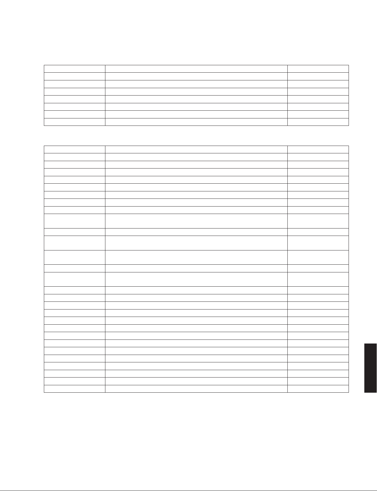
■ CONTENTS
TO SERVICE PERSONNEL ........................................2–4
PREVENTION OF ELECTROSTATIC DISCHARGE ......5
FRONT PANEL ...............................................................6
REAR PANELS ...........................................................6–8
REMOTE CONTROL PANEL .......................................... 8
SPECIFICATIONS /
INTERNAL VIEW .......................................................... 10
DISASSEMBLY PROCEDURES /
TEST MODE /
UPDATING FIRMWARE /
ファームウェアの書き込み
101118
参考仕様
テストモード
.........................................9
分解手順
...................................14–15
.....................................16–20
........... 11–13
Copyright © 2008 All rights reserved.
This manual is copyrighted by YAMAHA and may not be copied or
redistributed either in print or electronically without permission.
IC DATA ...................................................................21–26
DISPLAY DATA .............................................................27
PIN CONNECTION DIAGRAMS ...................................28
BLOCK DIAGRAM ........................................................ 29
PRINTED CIRCUIT BOARDS .................................30–38
SCHEMATIC DIAGRAMS ....................................... 39–42
REPLACEMENT PARTS LIST ................................ 43–53
REMOTE CONTROL ...............................................54–55
P.O.Box 1, Hamamatsu, Japan
animate '08.10
CD-S700

CD-S700
■ TO SERVICE PERSONNEL
1. Critical Components Information
Components having special characteristics are marked ⚠ and
must be replaced with parts having specifications equal to those
originally installed.
2. Leakage Current Measurement (For 120V Models Only)
When service has been completed, it is imperative to verify
that all exposed conductive surfaces are properly insulated
from supply circuits.
• Meter impedance should be equivalent to 1500 ohms shunted
by 0.15 μF.
WALL
OUTLET
• Leakage current must not exceed 0.5mA.
• Be sure to test for leakage with the AC plug in both polarities.
EQUIPMENT
UNDER TEST
INSULATING
TABLE
AC LEAKAGE
TESTER OR
EQUIVALENT
WARNING: CHEMICAL CONTENT NOTICE!
This product contains chemicals known to the State of California to cause cancer, or birth defects or other reproductive
harm.
DO NOT PLACE SOLDER, ELECTRICAL/ELECTRONIC OR PLASTIC COMPONENTS IN YOUR MOUTH FOR ANY REASON
WHATSOEVER!
Avoid prolonged, unprotected contact between solder and your skin! When soldering, do not inhale solder fumes or
expose eyes to solder/flux vapor!
If you come in contact with solder or components located inside the enclosure of this product, wash your hands before
handling food.
About lead free solder /
All of the P.C.B.s installed in this unit and solder joints are
soldered using the lead free solder.
Among some types of lead free solder currently available,
it is recommended to use one of the following types for
the repair work.
• Sn + Ag + Cu (tin + silver + copper)
• Sn + Cu (tin + copper)
• Sn + Zn + Bi (tin + zinc + bismuth)
Caution:
As the melting point temperature of the lead free solder
is about 30°C to 40°C (50°F to 70°F) higher than that of
無鉛ハンダについて
本機に搭載されているすべての基板およびハンダ付けに
よる接合部は無鉛ハンダでハンダ付けされています。
無鉛ハンダにはいくつかの種類がありますが、修理時に
は下記のような無鉛ハンダの使用を推奨します。
Sn+Ag+Cu(錫+銀+銅)
Sn+Cu(錫 + 銅)
Sn+Zn+Bi(錫 + 亜鉛 + ビスマス)
注意:
無鉛ハンダの融点温度は通常の鉛入りハンダに比べ 30 〜
40℃程度高くなっていますので、それぞれのハンダに合っ
たハンダごてをご使用ください。
the lead solder, be sure to use a soldering iron suitable
to each solder.
CD-S700
2

CD-S700
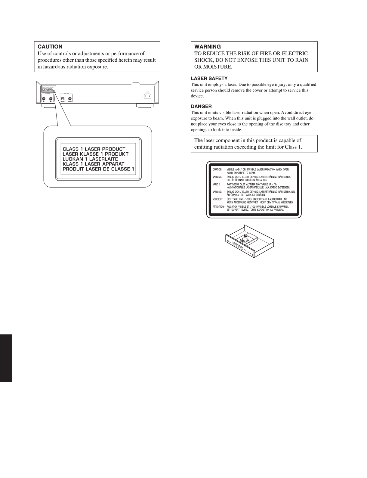
WARNING: Laser Safety
This product contains a laser beam component. This
component may emit invisible, as well as visible radiation, which may cause eye damage. To protect your
eyes and skin from laser radiation, the following precautions must be used during servicing of the unit.
1) When testing and/or repairing any component within
the product, keep your eyes and skin more than
30 cm/1 feet away from the laser pick-up unit at all
times. Do not stare at the laser beam at any time.
2) Do not attempt to readjust, disassemble or repair the
laser pick-up, unless noted elsewhere in this manual.
3) CAUTION: Use of controls, adjustments or performance of procedures other than those specified herein
may result in hazardous radiation exposure.
Laser Emitting conditions:
1) When the Top Cover is removed, and the STANDBY/
ON SW is turned to the “ON” position, the laser component will emit a beam for several seconds to detect if a disc is present. During this time (5-10 sec.)
the laser may radiate through the lens of the laser
pick-up unit. Do not attempt any servicing during this
period!
If no disc is detected, the laser will stop emitting the
beam. When a disc is loaded, you will not be exposed to any laser emissions.
2) The laser power level can be adjusted with the VR
on the pick-up PWB, however, this level has been set
by the factory prior to shipping from the factory. Do
not adjust this laser level control unless instruction is
provided elsewhere in this manual. Adjustment of this
control can increase the laser emission level from the
device.
警告:レーザーの安全対策
本機はレーザー光線を放射する部品を搭載しています。
この部品が放射するレーザー光線は目に損傷を起こしま
す。このレーザー光線から目及び肌を保護するために、
本機の修理作業中は下記の注意を厳守してください。
1) テスト時または修理時、目及び肌を光ピックアップか
ら 30cm 以上離してください。いかなる場合もレー
ザー光線を見つめないでください。
2) 光ピックアップの再調整及び分解はしないでくださ
い。
3) このマニュアル上で指定されている以外の制御、調整、
手順はレーザー光線を照射される結果を招く恐れがあ
ります。
レーザー放射条件
1) トップカバーを取り外し STANDBY/ON スイッチを ON
にすると、ディスク検知のため5〜10秒間、光ピッ
クアップからレーザー光線が放射されます。この間、
修理はしないでください。
ディスクが検知されなければ、レーザー光線の放射は
停止します。ディスクがセットされている場合、ディ
スクで遮られるのでレーザー光線は修理担当者に届き
ません。
2) レーザーパワーレベルは光ピックアップ基板上の VR
により調整可能ですが、工場出荷前に調整セット済み
なので、この VRは廻さないでください。この VRを廻
すと装置からのレーザー光線の放射レベルが上がる恐
れがあります。
Laser Diode Properties
Material: GaAlAs
Wavelength: 790 nm
Laser Output: max. 1.23 μW *
* This output is the value measured
at a distance of about 200 mm from
the objective lens surface on the
Optical Pick-up Block.
レーザー
レーザータイプ:GaAlAs
波長: 790nm
レーザー出力: 最大 1.23 μ W
CD-S700
3
CD-S700
Warning for power supply
The primary side of the power supply carries live mains voltage when the player is connected to the mains even
when the player is switched off !
This primary area is not shielded so it is possible to accidentally touch copper tracks and/or components when servicing
the player.
Service personnel have to take precautions to prevent touching this area or components in this area.
Note:
The screws on the DVD mechanism may never be touched, removed or re-adjusted.
Handle the DVD mechanism with care when the unit has to be exchanged!
The DVD mechanism is very sensitive for dropping or giving shocks.
CD-S700
4
CD-S700
■ PREVENTION OF ELECTROSTATIC DISCHARGE
Some semiconductor (solid state) devices can be damaged easily by static electricity. Such components commonly are
called Electrostatically Sensitive (ES) Devices. Examples of typical ES devices are integrated circuits and some field-effect
transistors and semiconductor “chip” components. The following techniques should be used to help reduce the incidence
of component damage caused by electro static discharge (ESD).
1. Immediately before handling any semiconductor component or semiconductor-equipped assembly, drain off any ESD
on your body by touching a known earth ground. Alternatively, obtain and wear a commercially available discharging
ESD wrist strap, which should be removed for potential shock reasons prior to applying power to the unit under test.
2. After removing an electrical assembly equipped with ES devices, place the assembly on a conductive surface such as
aluminum foil, to prevent electrostatic charge buildup or exposure of the assembly.
3. Use only a grounded-tip soldering iron to solder or unsolder ES devices.
4. Use only an anti-static solder removal device. Some solder removal devices not classified as “anti-static (ESD protected)” can generate electrical charge sufficient to damage ES devices.
5. Do not use freon-propelled chemicals. These can generate electrical charges sufficient to damage ES devices.
6. Do not remove a replacement ES device from its protective package until immediately before you are ready to install it.
(Most replacement ES devices are packaged with leads electrically shorted together by conductive foam, aluminum foil
or comparable conductive material).
7. Immediately before removing the protective material from the leads of a replacement ES divice, touch the protective
material to the chassis or circuit assembly into which the device will be installed.
CAUTION: Be sure no power is applied to the chassis or circuit, and observe all other safety precautions.
8. Minimize bodily motions when handling unpackaged replacement ES devices. (Otherwise harmless motion such as
brushing together of your fabric clothes or lifting of your foot from a carpeted floor can generate static electricity (ESD)
sufficient to damage an ES device).
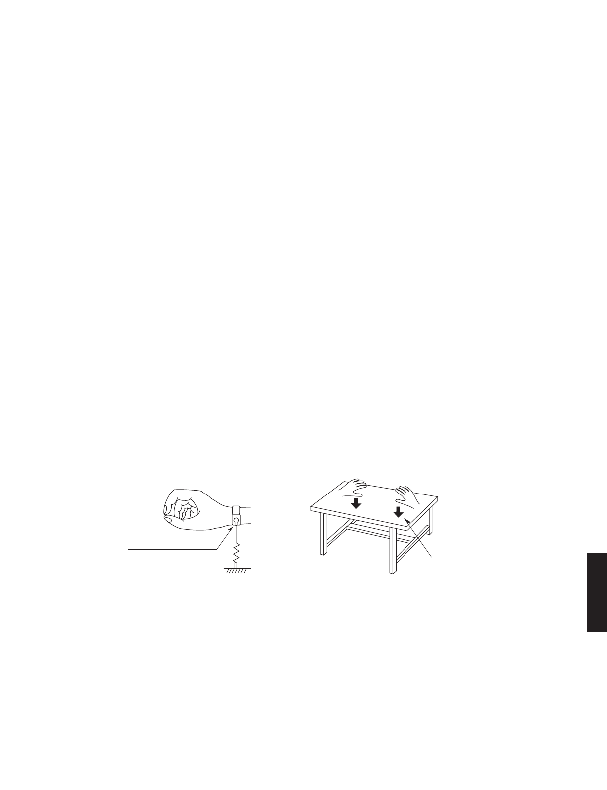
Grounding for electrostatic breakdown prevention
1. Human body grounding.
Use the antistatic wrist strap to discharge the static electricity from your body.
2. Work table grounding.
Put a conductive material (sheet) or steel sheet on the area where the optical pickup is placed and ground the sheet.
Caution:
The static electricity of your clothes will not be grounded through the wrist strap. So take care not to let your clothes touch
the optical pickup.
Anti-static wrist strap
1M-ohms
Conductive material
(sheet) or steel sheet
CD-S700
5
CD-S700
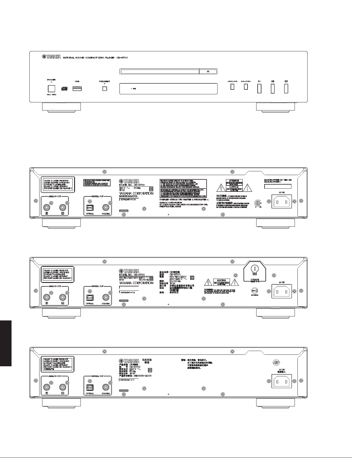
■ FRONT PANEL
CD-S700 (U, R, T, K, A, B, G, L, J models)
■ REAR PANELS
CD-S700 (U model)
CD-S700 (R model)
CD-S700 (T model)
CD-S700
6
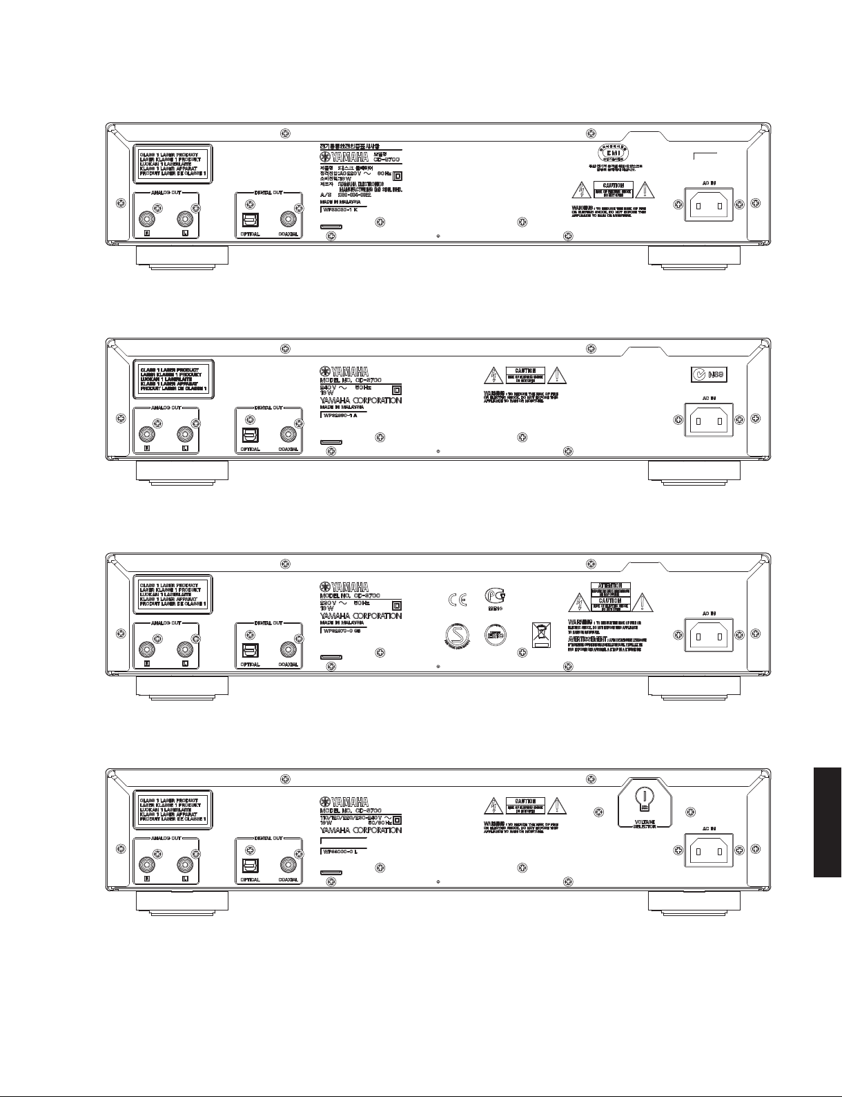
CD-S700 (K model)
CD-S700 (A model)
CD-S700
CD-S700 (B, G models)
CD-S700 (L model)
CD-S700
7
CD-S700
CD-S700 (J model)
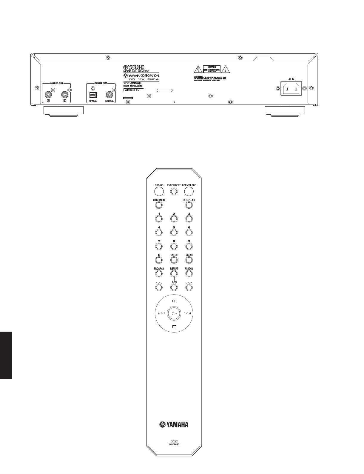
■ REMOTE CONTROL PANEL
CDX-7
CD-S700
8
CD-S700
■ SPECIFICATIONS /
■ Audio Section /
Output Level /
オーディオ部
出力レベル
(1 kHz, 0 dB)
参考仕様
................................................................................. 2 ±0.3 V
Signal to Noise Ratio /
信号対雑音比
......................................................................110 dB or more
Dynamic Range /
ダイナミックレンジ
......................................................................100 dB or more
Harmonic Distortion / 歪率 (1 kHz)
......................................................................0.002 % or less
Frequency Response /
周波数特性
...................................................................... 2 Hz to 20 kHz
Digital Output Terminal /
デジタル出力
.........................................................Optical x 1, Coaxial x 1
■ General /
Power Consumption /
総合
消費電力
U, R, T, K, A, B, G, L models ....................................... 16 W
J model .......................................................................... 10 W
Power Supply /
電源電圧
U model ........................................................... AC 120 V, 60 Hz
R, L models ..................... AC 110/120/220/230-240 V, 50/60 Hz
T model ............................................................ AC 220 V, 50 Hz
K model ............................................................ AC 220 V, 60 Hz
A model ............................................................ AC 240 V, 50 Hz
B, G models ..................................................... AC 230 V, 50 Hz
J model ....................................................... AC 100 V, 50/60 Hz
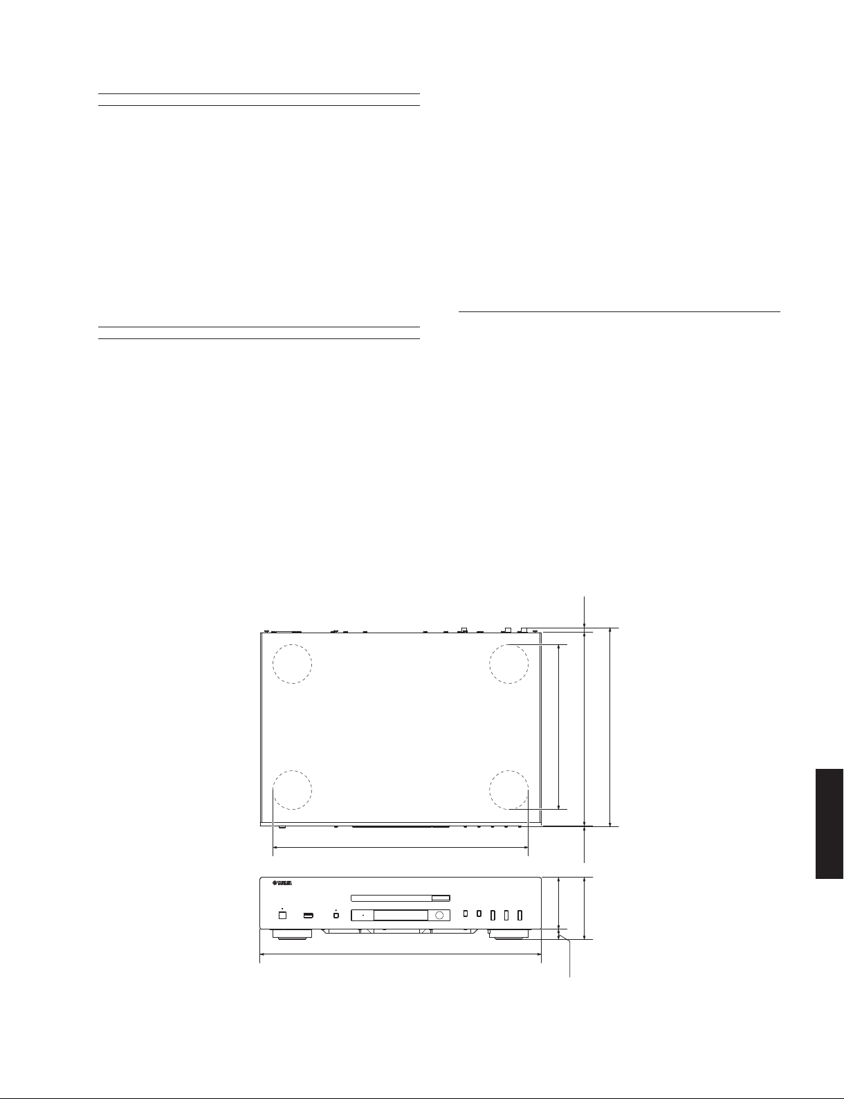
Dimensions (W x H x D) /
寸法(幅 × 高さ × 奥行き)
...................435 x 96 x 300 mm (17-1/8" x 3-3/4" x 11-3/4")
Weight / 質量
...........................................................6.2 kg (13 lbs. 11 oz.)
Finish /
仕上げ
Black color ........................U, R, T, K, A, B, G, L, J models
Silver color ........................U, R, T, K, A, B, G, L, J models
Accessories /
付属品
Remote control ................................................................ x 1
Battery (R6, AA, UM-3) ................................................... x 2
RCA stereo cable (1.5 m) ............................................... x 1
Power cable (2 m) .......................................................... x 1
* Specifications are subject to change without notice due to product
improvements.
※ 参考仕様および外観は予告なく変更されることがあります。
U .... U.S.A. and Canadian models
R ......................... General model
T..........................Chinese model
K ...........................Korean model
A ......................Australian model
B ............................British model
G ...................... European model
L...................... Singapore model
J ........................Japanese model
• DIMENSIONS /
寸法図
395 (15-9/16")
435 (17-1/8")
6
(1/4")
300 (11-3/4")
255 (10-1/16")
4
(3/16")
80 (3-1/8")
96 (3-3/4")
16 (5/8")
310 (12-3/16")
CD-S700
Unit: mm (inch)
単位:mm(インチ)
9
CD-S700
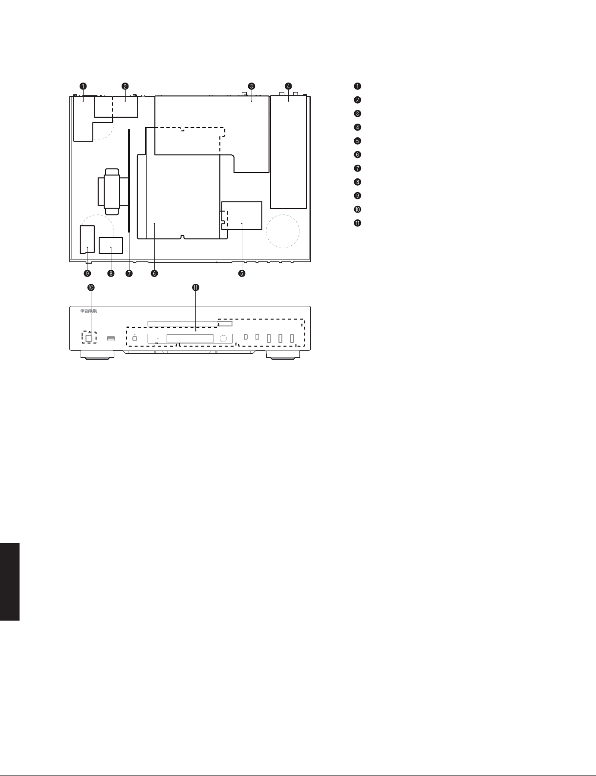
■ INTERNAL VIEW
OPERATION (5) P.C.B.
OPERATION (7) P.C.B. (R, L models)
DIGITAL P.C.B.
OPERATION (3) P.C.B.
OPERATION (9) P.C.B.
Loader Mechanism Ass'y
OPERATION (4) P.C.B.
OPERATION (8) P.C.B.
OPERATION (6) P.C.B.
OPERATION (2) P.C.B.
OPERATION (1) P.C.B.
CD-S700
10
CD-S700
■ DISASSEMBLY PROCEDURES /
(Remove parts in the order as numbered.)
Disconnect the power cable from the AC outlet.
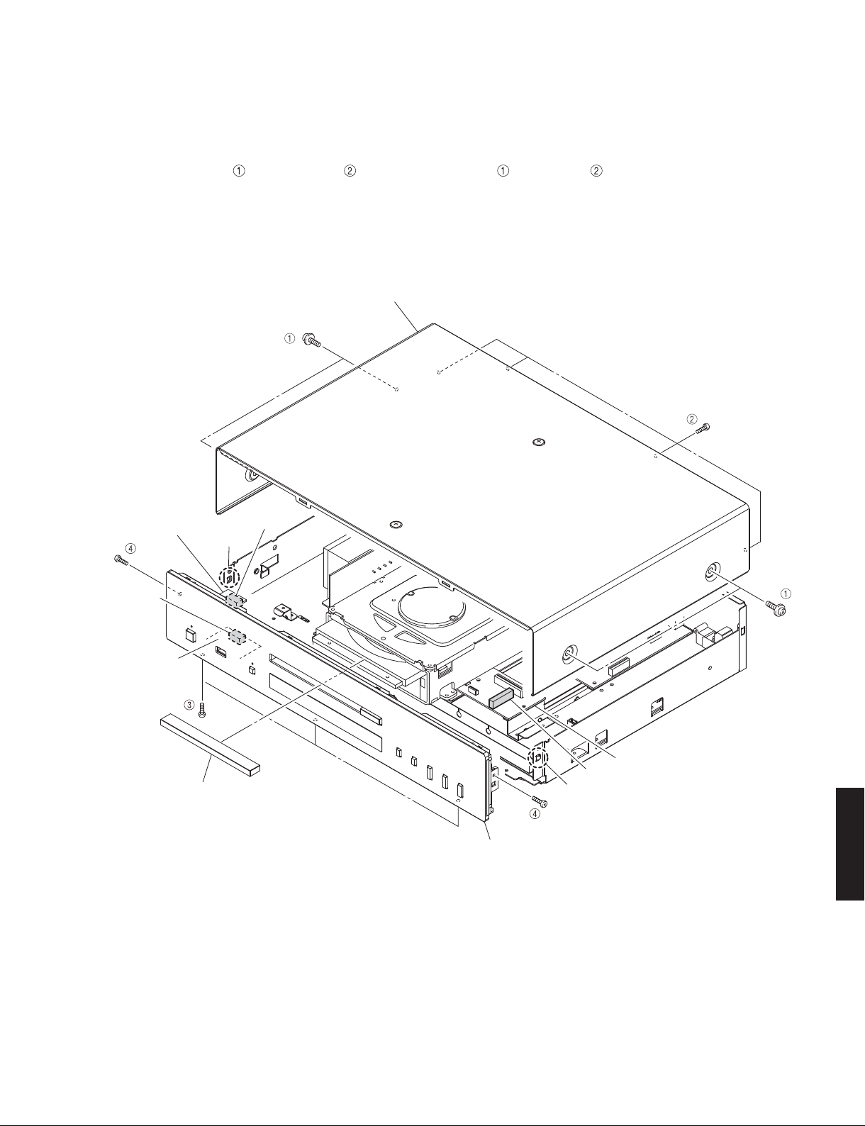
1. Removal of Top Cover
a. Remove 4 screws ( ) and 4 screws ( ). (Fig. 1)
b. Remove the top cover. (Fig. 1)
Top cover
トップ カ バ ー
分解手順
(番号順に部品を取り外してください。)
AC 電源コンセントから、電源コードを抜いてください。
1. トップカバーの外し方
a. ( ) ネジ 4 本、( ) のネジ 4 本を外します。(Fig.1)
b. トップカバーを取り外します。(Fig.1)
OPERATION (1)
P. C . B .
CB162
OPERATION (8)
P. C . B .
Lid
リッド
Hook
フック
CB205
Front panel ass'y
フロントパネルASSY
Fig. 1
CB152
Hook
フック
OPERATION (9) P.C.B.
CD-S700
11
CD-S700
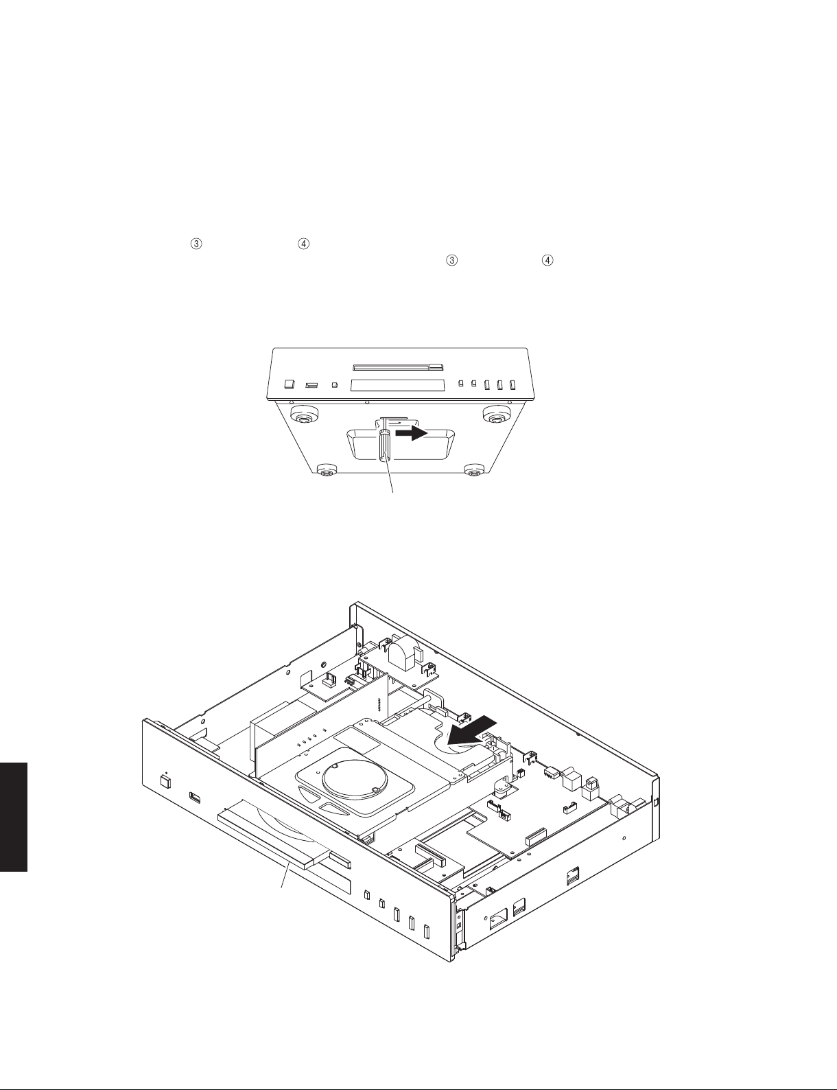
2. Removal of Front Panel Ass’y
a. Using a flatblade screwdriver, move the slider at the
bottom in the direction of the arrow shown below. (Fig. 2)
* The disc tray lock will be released but will not
come out.
b. Push out the disc tray by pushing its rear. (Fig. 3)
c. Remove the lid. (Fig. 1)
d. Close the disc tray by pushing its front.
e. Remove 4 screws (
f. Remove CB152, CB162 and CB205. (Fig. 1)
g. Release 2 hooks and then remove the front panel
ass’y. (Fig. 1)
) and 2 screws ( ). (Fig. 1)
2. フロントパネル ASSY の外し方
a. マイナスドライバーで底面のスライダーを下図の矢印
の方向に動かします。(Fig.2)
※ このとき、ディスクトレイは押し出されません。
b. ディスクトレイの後方を押し、ディスクトレイを押し
出します。(Fig.3)
c. リッドを取り外します。(Fig.1)
d. ディスクトレイの前方を押し、ディスクトレイを閉じ
ます。
e. (
) のネジ 4 本、( ) のネジ 2 本を外します。(Fig.1)
f. CB152、CB162、CB205 を外します。(Fig.1)
g. フック 2 箇所を外し、フロントパネル ASSY を取り外
します。(Fig.1)
Flatblade screwdriver
マイナスドライバー
Fig. 2
CD-S700
Disc tray
ディスクトレイ
12
Fig. 3
CD-S700
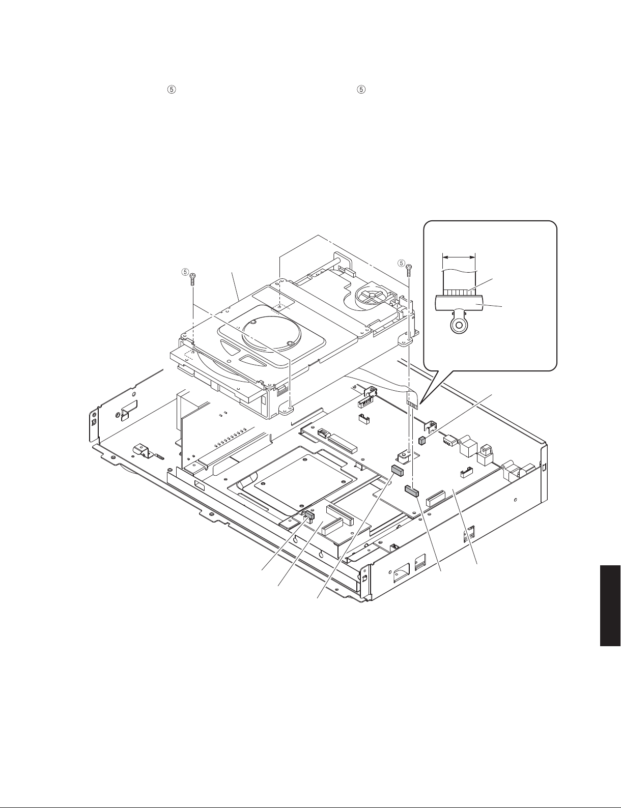
3. Removal of Loader Mechanism Ass’y
a. Remove 4 screws ( ). (Fig. 4)
b. Remove CB153, CB302 and CB602. (Fig. 4)
c. Remove CB604 and ground the terminal face of the
flexible flat cable with a clip or the like. (Fig. 4)
d. Lift loader mechanism ass’y up slightly and move it
backward to remove. (Fig. 4)
Loader mechnism ass'y
ローダーメカASSY
3.ローダーメカ ASSY の外し方
a. ( ) のネジ 4 本を外します。(Fig.4)
b. CB153、CB302、CB602 を外します。(Fig.4)
c. CB604 を外し、カード電線の端子面をクリップ等で
アースします。(Fig.4)
d. ローダーメカ ASSY を持ち上げて、後方へ取り外しま
す。(Fig.4)
17 mm
(0.67")
Terminal side
端子面
Clip
クリップ
Use a clip or the like to ground
the unit.
クリップ 等 で ア ースしてくだ さい 。
CB153
OPERATION (9) P.C.B.
CB602
Fig. 4
CB604
CB302
DIGITAL P.C.B.
CD-S700
13
CD-S700
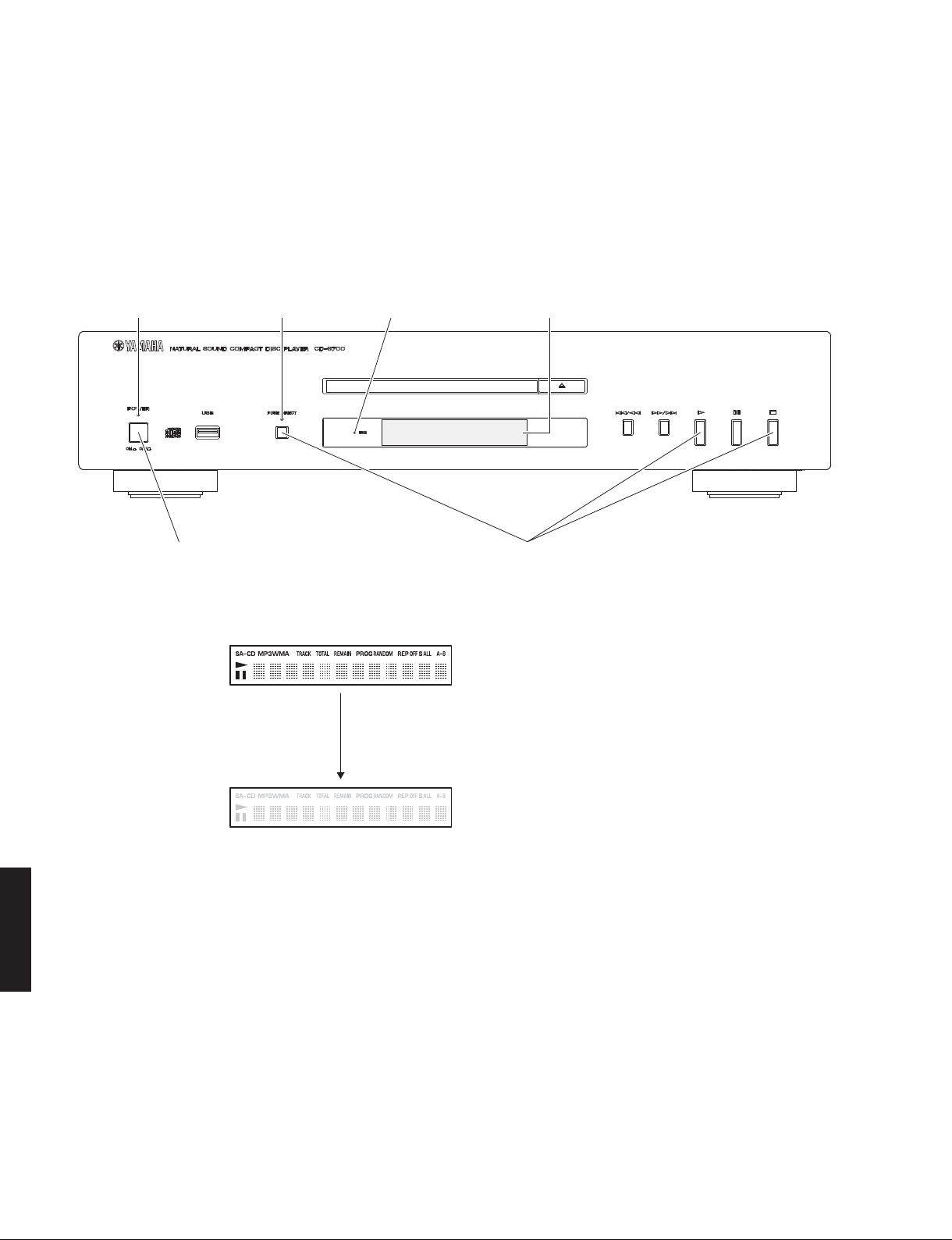
■ TEST MODE /
Check the FL display and indicators for display/indication
condition.
Check the FL display and Indicators
●
1. Press the “POWER ON/OFF” switch inward to the
ON position while simultaneously pressing those
3 keys of this unit as indicated in the figure below,
and keep pressing those 3 keys.
"POWER" indicator
テストモード
"USB" indicator"PURE DIRECT" indicator FL display
FL ディスプレイとインジケーターの表示状態をチェック
します。
● FL ディスプレイとインジケーターの確認
1. 本 機の下図に 示す 3 つのキーを同 時 に押しながら
“MASTER ON/OFF” スイッチを押してオンにし、3 つ
のキーを押し続けます。
"POWER ON/OFF" switch
2. With these 3 keys pressed continuously, check
that all indicators (POWER, PURE DIRECT, USB)
are lit. At the same time, check that all segments
of the FL display are lit.
CD-S700
3. Release these 3 keys. Then check that all indicators (POWER, PURE DIRECT, USB) as well as all
segments of the FL display are turned off.
4. The Test Mode is activated.
Press the "POWER ON/OFF" switch inward to the ON position while pressing these keys.
これらのキーを同時に押しながら、“POWERON/OFF” スイッチを押してオンにします。
FL display /
Release the key
キーを離す
FL ディスプレイ表示
All segments ON
全セグメント点灯
All segments OFF
全セグメント消灯
2. 3 つのキーを押したまま、全てのインジケーター
(POWER、PUREDIRECT、USB)が点灯しているこ
とを確認します。
同時に、FL ディスプレイの全セグメントが点灯し
ていることを確認します。
3. 3 つのキーを離します。
全てのインジケーター(POWER、PUREDIRECT、
USB)と、FL ディスプレイの全セグメントが消灯
していることを確認します。
4. テストモードが起動します。
14
CD-S700
Operation Procedure of Test Mode
●
Function list of panel keys /
Panel key /
OPEN/CLOSE Disc tray open/close /
PLAY Trace on /
STOP Trace off /
PAUSE – –
SKIP+/SEARCH+ Trace on /
SKIP-/SEARCH- – –
PURE DIRECT – –
パネルキー
Function list of remote control keys /
Key /
キー
CD/USB – –
PURE DIRECT – –
OPEN/CLOSE Disc tray open/close /
DIMMER – –
DISPLAY Firmware version is displayed. /
1 Laser on /
2 Focus on /
3 TE measure /
4
5 Traverce stop /
6
7
8 Spindle off /
9
0––
ENTER – –
CLEAR – –
PROGRAM – –
REPEART – –
RANDOM – –
SEARCH - – –
A-B REPEAT – –
SEARCH + – –
PAUSE – –
SKIP - – –
PLAY Trace on /
SKIP + Trace on /
STOP Trace off /
テストモード時のパネルキー
ディスクトレイ オープン/クローズ
トレースオン
トレースオフ
トレースオン
テストモード時のリモコンキー
ディスクトレイ オープン/クローズ
レーザーオン
フォーカスオン
TE 測定
Traverce in /
トラバースイン
トラバースストップ
Traverce out /
トラバースアウト
Spindle reverce /
スピンドルリバース
スピンドルオフ
Spindle on /
スピンドルオン
トレース オン
トレース オン
トレース オフ
* Press “5” key to stop traverce. /
※
* Press “5” key to stop traverce. /
※
* Press “8” key to stop spindle. /
※
* Press “8” key to stop spindle. /
※
Function /
Function /
ファームウェアバージョン表示
“5”
キーを押してトラバースを停止してください。
“5”
キーを押してトラバースを停止してください。
“8”
キーを押してスピンドルを停止してください。
“8”
キーを押してスピンドルを停止してください。
● テストモード時の操作
機能
機能
Display /
OPEN / CLOSE
TRACE on
TRACE off
TRACE on
Display /
OPEN / CLOSE
Yxxx xxxx
LASER on
FOCUS on
TE measure
TRV in
TRV stop
TRV out
SPDL rev
SPDL stop
SPDL on
TRACE on
TRACE on
TRACE off
表示
表示
CD-S700
Canceling Test Mode
●
Press the “POWER ON/OFF” switch of this unit to release it outward to the OFF position.
● テストモードの解除
本機の“POWERON/OFF”スイッチを押してオフにします。
15
CD-S700
■ UPDATING FIRMWARE /
After replacing the following parts update the latest firmware according to the following procedure.
DIGITAL P.C.B.
Microprocessor (IC304) of DIGITAL P.C.B.
Required tools
●
• Program downloader programs ....... FlashSta.exe
• Firmware .............................................. CDS700.S
• RS232C cross cable “D-sub 9 pin female”
(Specifications)
Pin No.2 RxD Pin No.2 RxD
Pin No.3 TxD Pin No.3 TxD
Pin No.5 GND Pin No.5 GND
Pin No.7 RTS Pin No.7 RTS
Pin No.8 CTS Pin No.8 CTS
• RS232C conversion jig (Part No.: AAX88050)
Preparation and precautions before starting
●
ファームウェアの書き込み
CDS700.id
the operation
• Download firmware downloader program and
firmware from the specified source to the same
folder of the PC.
• Prepare the above specified RS232C cross cable.
• While writing, keep the other application software
on the PC closed.
It is also recommended to keep the software on
the task tray closed as well.
下記の部品を交換した場合、下記の手順により最新の
ファームウェアの書き込みを行ってください。
DIGITALP.C.B.
DIGITALP.C.B. のマイコン(IC304)
● 必要なツール
・ プログラム書き込み用プログラム....... FlashSta.exe
・ ファームウェア.....................................................CDS700.S
CDS700.id
・ RS232C クロスケーブル “D-sub9pin メス”
(仕様)
PinNo.2RxD PinNo.2RxD
PinNo.3TxD PinNo.3TxD
PinNo.5GND PinNo.5GND
PinNo.7RTS PinNo.7RTS
PinNo.8CTS PinNo.8CTS
・ RS232C変換冶具(部品番号:AAX88050)
● 操作前の準備と注意
・ PC へ指定のダウンロード先からファームウェア
書き込み用プログラムおよび、ファームウェアを
同じフォルダにダウンロードしてください。
・ RS232C クロスケーブルは必ず上記仕様のものを
用意してください。
・ 書き込み時は、PC 上の他のアプリケーションソ
フトは閉じてください。
さらに、タスクトレイ上にあるソフトも閉じてお
くことを推奨します。
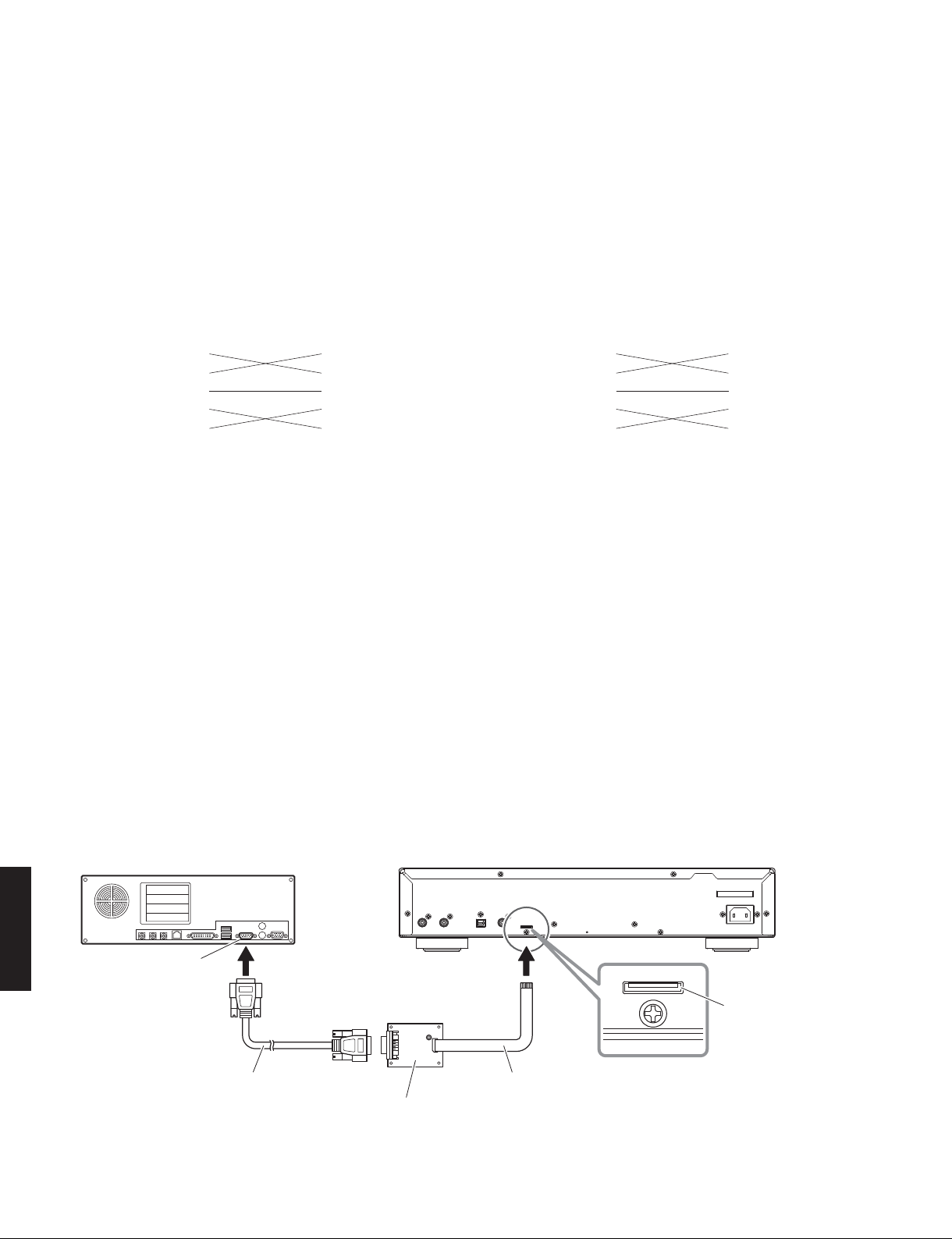
Connection
●
Connect the writing port of this unit to the serial
port (RS232C) of the PC with RS232C cross cable,
RS232C conversion jig and flexible flat cable as
shown below. (Fig. 1)
PC
CD-S700
Serial port (RS232C)
RS232C cross cable
RS232Cクロスケーブル
RS232C conversion jig
RS232C変換冶具
This unit / 本機 Rear side
● 接続
本機の書き込み用ポートと PC のシリアルポート
(RS232C)を下記のように接続します。(Fig.1)
Writing port
書き込み用ポート
Flexible flat cable 8P
カード電線8P
Fig. 1
16
CD-S700
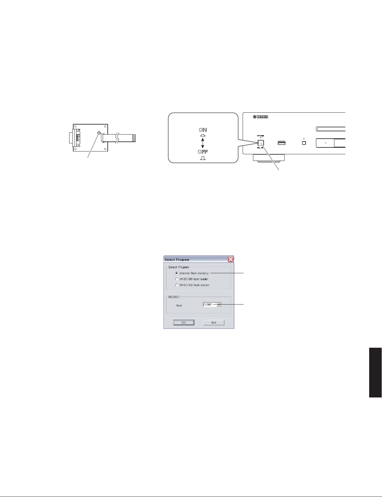
Operation Procedures
●
1. Connect the power cable of this unit to the AC
outlet.
2. While pressing the reset switch of RS232C conversion jig, press the “POWER ON/OFF” switch of
this unit inward to the ON position. (Fig. 2)
RS232C conversion jig
RS232C変換冶具
Reset switch
リセットスイッチ
● 操作手順
1. 本機の電源コードを AC コンセントに接続します。
2. RS232C 変換冶具のリセットスイッチを押しなが
ら、本機の “POWERON/OFF” スイッチを押して
オンにします。(Fig.2)
Front side Front side
"POWER ON / OFF" switch
"POWER ON / OFF" switch
Fig. 2
3. Start up FlashSta.exe, the screen will appear as
shown below. (Fig. 3)
4. Select the port and data to be transmitted. (Fig. 3)
• Select Program
Select Internal flash memory
• RS232C
Select the port of RS-232C
* For selection of the port, COM1 to 4 can be
used.
As COM5 or higher port cannot be used, select out of COM 1 to 4 of the setting on the PC
side.
3. FlashSta.exe を立ち上げます。
すると下記の画面が表示されます。(Fig.3)
Select Internal flash memory
Internalflashmemory を選択します
Select the port of RS-232C
接続している RS-232C ポートを選択します
Fig. 3
CD-S700
4. 送信データ、ポートを選択します。(Fig.3)
・ SelectProgram
Internalflashmemory を選択します。
・ RS232C
接続している RS-232 Cポートを選択します。
※ ポートの選択は COM1 〜 4 までが使用できま
す。
COM5 以上は使用できませんので、PC 側の設
定で COM1 〜 4 を選択してください。
17

CD-S700
5. Click [Refer...]. And select the firmware name.
(Fig. 4)
* The ID code and MCU type are loaded auto-
matically when the file is selected. (Fig. 4)
Click [OK]. (Fig. 4)
Click to open the window
ここをクリックすると
ウィンドウが開きます
5.[Refer...]をクリックし、書き込むファームウェア
を選択します。(Fig.4)
※ ID、および MCUType は書き込みファイル選
択時、自動的に取り込まれます。(Fig.4)
[OK]をクリックします。(Fig.4)
Fig. 4
6. Click [E.P.R.], the screen appears as shown below. (Fig. 5)
Click [OK] to start writing. (Fig. 5)
6.[E.P.R]をクリックすると、下記の画面が表示さ
れます。(Fig.5)
[OK]をクリックし、書き込みを開始します。
(Fig.5)
Writing being executed.
書き込み中
CD-S700
18
Fig. 5

CD-S700
7. When the program transmission is completed, the
screen appears as shown below. (Fig. 6)
Click [OK] to end the procedure. (Fig. 6)
7. プログラムの送信が終了すると、下記の画面が表
示されます。(Fig.6)
[OK]をクリックして完了します。(Fig.6)
Fig. 6
8. Press the “POWER ON/OFF” switch of this unit to
release it outward to the OFF position.
9. Disconnect the power cable of this unit from the
AC outlet.
10. End “FlashSta.exe”.
11. Disconnect the RS232C cross cable, RS232C
conversion jig and flexible flat cable.
8. 本機の “POWERON/OFF” スイッチを押してオフ
にします。
9. 本機の電源コードを AC コンセントから抜きます。
10.“FlashSta.exe” を終了します。
11.RS232C クロスケーブル、RS232C 変換アダプター
カード電線を取り外します。
CD-S700
19

CD-S700
Confirmation of firmware version
●
Press the “POWER ON/OFF” switch inward to the ON
position while simultaneously pressing the “PLAY”
and “STOP” keys of this unit, and then release these
two keys. (Fig. 7)
The firmware version is displayed. (Fig. 7)
"POWER ON / OFF" switch "PLAY" key
"POWER ON / OFF" switch
● ファームウェアバージョンの確認
本機の “PLAY” キーと “STOP” キーを押しながら、
“POWERON/OFF” スイッチを押してオンにし、これ
ら 2 つのキーを放します。(Fig.7)
ファームウェアバージョンが表示されます。(Fig.7)
"STOP" key
When the power is ON (All light up)
電源オン時(全点灯)
Every time you press the “DISPLAY” key, the display
changes in the order as shown below.
The firmware version of the microprocessor (IC304) and its date of update are displayed.(Initial
display)
The date of update
更新日付
The firmware version
ファームウェアバージョン
マイコン(IC304)のファームウェアバージョンおよび更新日付を表示します。(初期表示)
Firmware version of microprocessor is displayed.
マイコンのファームウェアバージョン表示
Fig. 7
リモコンの “DISPLAY” キーを押すたびに、下図の順
で表示が切り替わります。
Remote control
"DISPLAY" key
The firmware version of the CDLSI (IC602) is displayed.
CD-S700
CDLSI(IC602)のファームウェアバージョンを表示します。
The firmware version of the USB-microprocessor (IC604) is displayed.
USB マイコン(IC604)のファームウェアバージョンを表示します。
Fig. 8
* When the displayed firmware version is different
from written firmware version, follow the steps
from 1 to 11 of operation procedures again.
20
※ 表示されたファームウェアのバージョンが、書き
込んだファームウェアのバージョンと異なる場
合、操作手順の 1 から 11 までをもう一度実施し
てください。

T
■ IC DATA
IC304: M30302FAPFP (DIGITAL P.C.B.)
Single-chip 16-bit microprocessor
Port P08Port P18Port P28Port P38Port P48Port P58Port P6
CD-S700
8
Peripheral function
Timer (16-bit)
Input (timer A) x3
Output (timer B) x3
Watchdog timer
(15-bit)
DMAC
(2-channel)
Note 1: ROM contents vary depending on types.
RAM contents vary depending on types.
Note 2:
USB_DET
SYS_DET
SYS_ROCI_U
SYS_ROCI_C
A/D converter
(10-bit X 18-channel
UART or clock synchronous type
CRC arithmetic circuit (CCITT)
(Polynomial : X
R1H R1L
SYS_I/O
R_PLUG
SYS_RICO_C
)
serial I/O
(3-channel)
16+X12+X5
+1)
M16C/60 series
Microprocessor core
R0LR0H
R2
R3
A0
A1
A1
FB
FB
SYS_RICO_U
USB_/EN
USB_FLG
VSS
FL_CS
System clock generator
X
SB
USP
ISP
INTB
PC
FLG
VCC2
FL_RES
LED_USB
LED_PDIRECT
X
IN-XOUT
CIN-XCOUT
Memory
ROM
(Note 1)
RAM
(Note 2)
Multiplier
LED_POWER
DOUT_MUTE
PCON3
PCON2
DAC_RESET
DAC_CS1
Port P7
Port P8
Port P8_5
Port P9
Port P10
AMUTE
8
7
8
8
TP336
TP337
TP338
TP339
TP340
TP341
TP342
SYS_DM
SYS_DA
KEY0
KEY1
KEY2
AVSS
VDET
VREF
VCC1
TRAY_SW4
CLAMP_SW2
TRAY_SW3
CLAMP_SW1
TRAY_SW2
TRAY_SW1
BYTE
XCIN
CNVSS
XCOUT
/RESET
M30302FAPFP
XIN
VSS
XOUT
VCC1
IR
KEY_O/C
KEY_PLAY
SEL S700/1330
CLAMP_MOTOR2
CLAMP_MOTOR1
TRAY_MOTOR2
TRAY_MOTOR1
FL_CLK
PCON1
VER_SEL2
VER_SEL1
CD_INT
COMCS
USB_IN
CD_NRST
DRV_STBY
COMCLK
COMSTS
COMCMD
RTS
DAC_SCLK/C
RXDO
DAC_SO/TXO
FL_DATA
CD-S700
21

CD-S700
CD-S700
No. Port Name Function Name I/O Detail of Function
1 P9_6/ANEX1 (No connected)
2 CLAMP_SW2 P9_5/ANEX0 I Clamp SW2
3 CLAMP_SW1 P9_4 I Clamp SW1
4 TRAY_SW4 P9_3
5 TRAY_SW3 P9_2/TB2IN I Tray SW3 / Loader mechanism specification confirm
6 TRAY_SW2 P9_1/TB1IN I Tray SW2
7 TRAY_SW1 P9_0/TB0IN I Tray SW1
8 BYTE BYTE I GND
9 CNVSS CNVSS Usually GND but VCC1 when writing FLASH
10 XCIN P8_7/XCIN (No connected)
11 XCOUT P8_6/XCOUT (No connected)
12 /RESET /RESET
13 XOUT XOUT
14 VSS VSS GND
15 XIN XIN
16 VCC1 VCC1
17 P8_5/NMI Pull-up resistor required
18 KEY_O/C P8_4/INT2 GND when writing FLASH
19 KEY_PLAY P8_3/INT1 (No connected)
20 IR P8_2/INT0 I Remote control
21 P8_1 (No connected)
22 SEL S700/1330 P8_0
23 CLAMP_MOTOR2 P7_7 O Clamp motor 2
24 CLAMP_MOTOR1 P7_6 O Clamp motor 1
25 TRAY_MOTOR2 P7_5/TA2IN O Tray motor 2
26 TRAY_MOTOR1 P7_4/TA2OUT O Tray motor 1
27 P7_3/CTS2/RTS2/TA1IN (No connected)
28 FL_CLK P7_2/CLK2/TA1OUT O FL control
29 P7_1/RXD2/SCL2/TA0IN (No connected)
30 FL_DATA P7_0/TXD2/SDA2/TA0OUT O FL control
31 DAC_SO/TXO P6_7/TXD1/SDA1 O TxD for DAC control / Rewriting FLASH commonly used
32 RXDO P6_6/RXD1/SCL1 I RxD for rewriting FLASH commonly used
33 DAC_SCLK/CT P6_5/CLK1 O CTS for DAC control / Rewriting FLASH commonly used
34 RTS P6_4/CTS1/RTS1/CTS0/CLKS1 I RTS for rewriting FLASH commonly used
35 COMCMD P6_3/TXD0/SDA0 O MODULE control
36 COMSTS P6_2/RXD0/SCL0 I MODULE control
37 COMCLK P6_1/CLK0 I MODULE control
38 P6_0/CTS0/RTS0 (No connected)
39 P5_7/RDY/CLKOUT (No connected)
40 DRV_STBY P5_6/ALE O MODULE control
41 P5_5/HOLD GND when writing FLASH
42 CD_NRST P5_4/HLDA O MODULE control
43 USB_IN P5_3/BCLK O MODULE control
44 COMCS P5_2/RD O MODULE control
45 CD_INT P5_1/WRH/BHE I MODULE control
46 P5_0/WRL/WR VCC1 when writing FLASH
47 VER_SEL1 P4_7/CS3 (No connected)
48 VER_SEL2 P4_6/CS2 (No connected)
49 P4_5/CS1 (No connected)
50 PCON1 P4_4/CS0 O output RELAY
51 AMUTE P4_3/A19 O Analog mute
52 P4_2/A18 O DAC control
53 DAC_CS1 P4_1/A17 O DAC control
54 DAC_RESET P4_0/A16 O DAC control
55 PCON2 P3_7/A15 (No connected)
56 PCON3 P3_6/A14 (No connected)
57 DOUT_MUTE P3_5/A13 (No connected)
58 LED_POWER P3_4/A12 O Indicator of power supply
59 LED_PDIRECT P3_3/A11 O Indicator of pure direct
60 LED_USB P3_2/A10 O Indicator of SACD
22

No. Port Name Function Name I/O Detail of Function
61 FL_RES P3_1/A9 O FL control
62 VCC2 VCC2
63 FL_CS P3_0/A8 O FL control
64 VSS VSS
65 USB_FLG P2_7/A7 (No connected)
66 USB_EN P2_6/A6 (No connected)
67 SYS_RICO_C P2_5/A5 (No connected)
68 SYS_RICO_U P2_4/A4 (No connected)
69 R_PLUG P2_3/A3 (No connected)
70 SYS_I/O P2_2/A2 (No connected)
71 SYS_ROCI_C P2_1/A1 (No connected)
72 SYS_ROCI_U P2_0/A0 (No connected)
73 P1_7/D15 (No connected)
74 SYS_DET P1_6/D14/INT4 (No connected)
75 USB_DET P1_5/D13/INT3 (No connected)
76 P1_4/D12 (No connected)
77 P1_3/D11 (No connected)
78 P1_2/D10 (No connected)
79 P1_1/D9 (No connected)
80 P1_0/D8 (No connected)
81 P0_7/AN0_7/D7 O Test point
82 TP336 P0_6/AN0_6/D6 O Test point
83 TP337 P0_5/AN0_5/D5 O Test point
84 TP338 P0_4/AN0_4/D4 I LOAD- monitor
85 TP339 P0_3/AN0_3/D3 O Test point
86 TP340 P0_2/AN0_2/D2 I LOAD+ monitor
87 TP341 P0_1/AN0_1/D1 O Test point
88 TP342 P0_0/AN0_0/D0 O Test point
89 SYS_DM P10_7/AN7/KI3 (No connected)
90 SYS_DA P10_6/AN6/KI2 (No connected)
91 P10_5/AN5/KI1 (No connected)
92 P10_4/AN4/KI0 (No connected)
93 KEY0 P10_3/AN3 I Analog input
94 KEY1 P10_2/AN2 I Analog input
95 KEY2 P10_1/AN1 I Analog input
96 AVSS AVSS
97 VDET P10_0/AN0 I MODULE control
98 VREF VREFF
99 VCC1 AVCC
100 P9_7/ADTRG (No connected)
CD-S700
23
CD-S700

CD-S700
IC604: MN103SFB5KYAA (DIGITAL P.C.B.)
USB microprocessor
N.C.
N.C.
N.C.
33
34
35
N.C.
32
INTERFACE
SYSTEM control
N.C.
N.C.
31
30
MEMORY
8 KB
USB
SIF
x 2
I2C
x 1
I/O port
34 pcs (3 V type)
8 pcs (5 V type)
CLOCK &
N.C.
29
N.C.
28
N.C.
27
MEMORY
16-bit x 2
N.C.
26
ROM
256 KByte
FLASH
DATA
RAM
8 KByte
8-bit x 4
USB_IN
25
TIMER
N.C.
24
32 bit
MICRO-
PROCESSOR
CORE
WDTx1
N.C.
23
N.C.
22
INTERRUPT
CONTROL
N.C.
21
DMA 4 CH
35 Factor
N.C.
20
OCD_SCL
OCD_SDA
19
18
VPP
17
16
15
14
MMOD1
MMOD0
NRST
N.C.
N.C.
VDD3
N.C.
VSS
N.C.
VDDI
N.C.
N.C.
N.C.
I2C_SCL
36
37
38
39
40
41
42
43
44
45
46
13
12
11
10
9
8
7
6
5
4
3
VSS
OSCO
OSCI
VDDI
VDD3
N.C.
AVDD
USBD+
VSS
USBD-
USBNPP
CD-S700
N.C.
I2C_SDA
47
48
49
VDD3
50
N.C.
51
N.C.
52
N.C.
53
VSS
54
55
CS
STREQ
56
N.C.
57
TX
58
RX
59
STCLK
60
N.C.
61
62
VDDI
STDATA
63
N.C.
2
1
64
N.C.
USBNOC
N.C.
24

No. Port Name Function Name Detail of Function
1 N.C.
2 USBNOC USB over-current input (negative polarity)
3 USBNPP USB, VBUS power output control terminal (negative polarity)
4 USBD- USB D- terminal
5 VSS AVSS Ground / Analog power supply for USB / Connect to VSS.
6 USBD+ USB D+ terminal
7 AVDD Analog power supply for USB / Connect to VDD33.
8 N.C.
9 VDD3 VDD33
10 VDDI VDD18/VOUT
11 OSCI
12 OSCO High-speed oscillation output terminal
13 VSS Ground
14 NRST Reset signal input terminal (negative polarity)
15 MMOD0 Operation mode setting terminal
16 MMOD1 Operation mode setting terminal
17 VPP
18 OCD_SDA Clock, data input/output terminal for on-chip debugger
19 OCD_SCL Clock, data input/output terminal for on-chip debugger
20
21
N.C.
22
23
24
25 USB_IN General purpose input/output port 0
26
27
28
29
30
31
N.C.
32
33
34
35
36
37
38 VDD3 VDD33
39 N.C.
40 VSS Ground
41 N.C.
42 VDDI VDD18
43
N.C.44
45
46 I2C_SCL P35/SCL3 General purpose input/output port 3
47 N.C.
48 I2C_SDA P33/SDA3 General purpose input/output port 3
49 VDD3 VDD5 I/O power supply (5V type I/O
Power for on-chip regulator (2.7V to 3.6V)
I/O power supply (2.7V to 3.6V)
Power for internal circuit (1.8V t±0.15V)
Connect all VDD18 terminals outside of chip.
Also, connect a 10μF capacitor between VDD18 and VSS of No.10 pin and place it
near LSI.
On-chip regulator output (1.8V ±0.15V)
High-speed oscillation input terminal (fosc)
(When PLL used: 6.33 MHz to 20 MHz)
Power for rewriting built-in Flash memory (3.3V ±0.3V) / only for Flash built in model
Power for on-chip regulator (2.7V to 3.6V)
I/O power supply (2.7V to 3.6V)
Power supply for internal circuit (1.8V ±0.15V)
Connect all VDD18 terminals outside of chip.
Also, connect a 10μF capacitor between VDD18 and VSS of No.10 pin and place it
near LSI.
CD-S700
CD-S700
25

CD-S700
No. Port Name Function Name Detail of Function
50 N.C.
51
N.C.
52
53 VSS Ground
54 STREQ PD5/IRQ2 External interrupt request signal input terminal
55 CS PD4/IRQ1 External interrupt request signal input terminal
56 N.C.
57 TX PD1/SBI2 Clock synchronization/start stop synchronization serial terminal
58 RX PD0/SBO2 Clock synchronization/start stop synchronization serial terminal
59 STCLK P92/SBT0 Serial clock input/output termina
60 N.C.
61 STDATA P90/SBO0 Serial data output terminal
Power supply for internal circuit (1.8V ±0.15V)
62 VDDI VDD18
63
N.C.
64
Connect all VDD18 terminals outside of chip.
Also, connect a 10μF capacitor between VDD18 and VSS of No.10 pin and place it
near LSI.
CD-S700
26

■ DISPLAY DATA
● V101 : 13-ST-81GINK (OPERATION (1) P.C.B.)
CD-S700
43
1
● PIN CONNECTION
Pin No. 12345678910111213141516171819
13GNXNXNXNXNXNXNXNXNXNXNXNXNXNXConnection
22
23
24
25
26
27
28
29
30
31
32
33
35
CS
40
LGND
34
CP
39
PGND
DA
38
VH
TSA
TSB
NX
NX
NX
NX
NX
NX
NX
NX
36
Pin No.
Connection
Pin No.
Connection
Note: 1) F1, F2 ..... Filament 2) NP ..... No pin 3) NX ..... No extended pin 4) DL ..... Datum line 5) LGND ..... Logic GND pin
6) PGND ..... Power GND pin 7) VH ..... High voltage supply pin 8) VDD ..... Logic voltage supply pin 9) CP ..... Shift register clock
10) DA ..... Serial data input 11) TSA, B ..... Test pin 12) CS ..... Chip select input pin 13) OSC ..... Pin for self-oscillation
14) RESET ..... Reset input 16) Q13G ..... Driver output port 17) 13G ..... Grid
37
VDD
43
F2
OSC
42
NP
RESET
41
NP
● GRID ASSIGNMENT
13G
21
NX
F1
NPNPQ13G
20
NX
1G
1-1 2-1 3-1 4-1 5-1
1-2 2-2 3-2 4-2 5-2
1-3 2-3 3-3 4-3 5-3
1-4 2-4 3-4 4-4 5-4
1-5 2-5 3-5 4-5 5-5
1-6 2-6 3-6 4-6 5-6
1-7 2-7 3-7 4-7 5-7
1G to 12G
2G 3G 4G 5G 6G 7G 8G 9G 10G 11 G 12G
● ANODE CONNECTION
1G to 12G
D0
D1
D2
D3
D4
D5
D6
D7
D8
D9
D10
D11
D12
D13
D14 5-3
1- 1
2-1
3-1
4-1
5-1
1- 2
2-2
3-2
4-2
5-2
1- 3
2-3
3-3
4-3
13G
1G to 12G
D15
D16
D17
D18
D19
D20
D21
D22
D23
D24
D25
D26
D27
D28
D29 5-6
1- 4
2-4
3-4
4-4
5-4
1- 5
2-5
3-5
4-5
5-5
1- 6
2-6
3-6
4-6
13G
–
–
–
–
–
–
–
–
–
–
–
–
–
D30
D31
D32
D33
D34
1G to 12G
1- 7
2-7
3-7
4-7
5-7
13G
–
–
–
–
–
CD-S700
27

CD-S700
■ PIN CONNECTION DIAGRAMS
• ICs
OP275GSR
8
BD9870FPS-E2
4
5
3
1
1
5
DSD1791DBR LB1641BD4829G-TR
28
1
14
1
10
M30302FAPFPM12L16161A-7TG MN103SFB5KYAA
80
81
50
1
4
1
25
100
1
PQ033ES3MXP R5523N001A-TR-F
1
3
R1172S331B-E2-F RP131S501D-E2-F
6
51
50
49
64
31
30
4
3
5
1
3
1
116
3348
32
17
6
3
1
TC7WU04F TS7ST00FTC74VHCT08AFT TC7SH08F
4
14
7
1
5
3
1
5
8
4
1
4
5
3
1
• Diodes
1N4002S 1SS355
D4SBN20-7101
FM203-W TE
MA-8039-H
MA8047-H
Anode
CD-S700
Cathode
MA8056-M 5.6V
MA8062-M
MA8130-M
MA8300-M 30.0V
RB050LA-40TR TP
RB501V-40
Cathode
Anode
–
AC
AC
+
RS203M-B-C-J80
+
AC
AC
–
• Transistors
2SA1037K
2SC2412K
2SD1938F
C
B
2SB1257
2SC44882SB709A
2SK208 DTC114EKA
2SD2014
C
E
B
C
E
E
B
B
C
E
G
D
S
3
1: GND
1
2: IN
2
3: OUT
28

ABCDEFGH I J
1
■ BLOCK DIAGRAM
CD-S700
OPERATION
CB161
USB Connector
V101
FL-Display
D104 POWER Indicator
D102 PURE DIRECT Indicator
D103 USB Indicator
SW101, SW102,
SW105-107
Front Panel Keys
2
USB+5
Loader Mechanism Ass'y
D+3.3V
IC606
Current
Limiter
USB Microprocessor:
MM1 (MN103SFB5K)
r Analyze Folder/File
/RST
IC604
D+/D-
USB IN
IC605
16Mbit SD-RAM
(Shock Proof)
TX/RX,
STCLK/DATA/REQ
3
Limit SW
A, B, C, D, E, F, PD
OPU
Focus
Tracking
Spindle Feed
4
OPEN/CLOSE
CLAMP UP/DOWN
LD, F+/F-, T+/T-
r Disc Control (Servo)
r EFM Demodulation
r Error Correction
r MP3/WMA Decode
r Output Digital Audio (I2S/SPDIF)
IC601
Actuator Driver
AN41010A
IC602
CD Controller:
./:"
SPDIF
M+8V
M
IC306
IC305
Loading Driver
Clamp Driver
FL_CLK/FL_Data
FL_CS/FL
/RST
COMCLK
COMCS
COMCMD
COMSTS
r $POUSPM'-%*41-":-&%
r %FUFDU3&.'SPOU1BOFM,FZ
r $POUSPM%"$
r %FUFDU48PG-PBEFSBOE$POUSPM
IC304
Microprocessor:
M30302FAPFP
OPEN/CLOSE
IC309
IC310
Buffer
Amp.
Remote
D+3.3V
IC307
Reset IC
X5868A0
BD4829G
U101
IN
DIGITAL
L307
Pulse
Trans
r 4FFQBHF→
SCHEMATIC DIAGRAM
Front Panel
r 4FFQBHF→
SCHEMATIC DIAGRAM
U300
OPTICAL
PJ300
COAXIAL
DC/DC Converter Regulator
5
OPERATION
Power Supply and Audio Out
6
7
r 4FFQBHF→
F201
SCHEMATIC DIAGRAM
SW201
Power Transformer
T201
±17V/80mA
D6 Q6
Q7
+20V/600mA
D215
+20V/600mA
+20V/200mA
D211-D214
+20V/120mA
Q201
A+12V
80mA
A-12V
-
80mA
+B1
+B2
FL +30V
21mA
FL AC+/- AC4.0V 150mA AUDIO OUT
Q5
+5DA
+3.3DA
IC4
Q102
FL +5V
3mA
IC1
Audio D/A Converter:
DSD1791
L+/L- R+/R-
IC2
Differential AMP. and L.P.F.
Q14-Q17
Mute Circuit
PJ1
L ch
MCLK
BCK
WCK
SDATA
R ch
DAC Control (SPI)
Zero Flag (Reserved)
AMUTE control
Q1
POWER MUTE
+B2
+20V/120mA
+B1
+20V/600mA
IC300
D+5V
30mA
DC/DC Converter
IC302
M+8V
500mA
IC303
D+3.3V
274mA
Regulator
USB+5V
500mA
IC311
29

ABCDEFGH I J
CD-S700
1
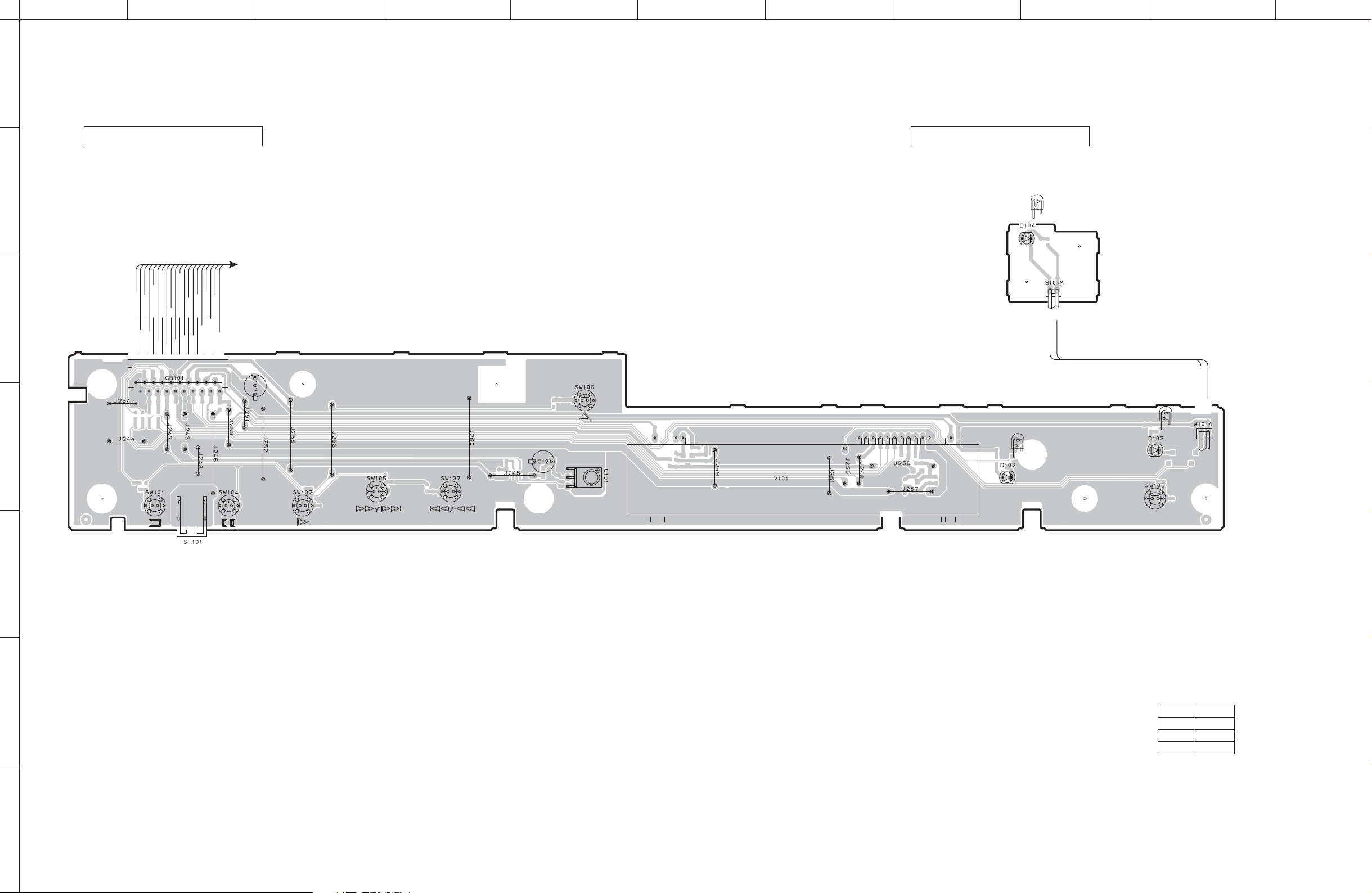
■ PRINTED CIRCUIT BOARDS
• Semiconductor Location
Ref no. Location
DIGITAL P.C.B. (Side A)
D300 G3
D302 G3
D303 G2
DIGITAL OUT
OPTICAL COAXIAL
2
IC310
5
Loader mechanism ass’y
Loading-
Loading+
148
IC309
1
253
25
26
IC605
Writing port
CB304
CB302
D309 E4
D601 C3
3
CB606
1
1
128
50
32
33
4
IC602
A-1
97
96 55
54
110110
IC307
13
54
C817
B-1
1
B-2
IC305IC306
100
2
81
Ref no. Location
D602 C3
D604 C4
IC300 G2
IC302 G3
IC303 F2
4
IC303
135
IC311
4
136
1
A-3
IC304
80 51
30
31
50
Ref no. Location
IC304 F4
IC305 E3
IC306 E3
IC307 E4
IC308 G5
IC300
INV
STBY
IC302
INV
STBY
(Writing port)
IC308
7
8
1
14
Ref no. Location
IC309 B3
IC310 B3
IC311 F3
IC601 D6
IC602 C4
FIN
VCC
OUT
FIN
VCC
OUT
CB608
32
17
IC604
A-2
Ref no. Location
IC604 H4
IC605 D3
IC606 H4
Q602 C3
CB300
4833
49
64
116
54
13
IC606
DGND
+B2
MGND
+B1
+30
ACFL2
ACFL1
FLGND
OPERATION (4)
(W208)
J810
POINT A-1 XL601 (Pin 109 of IC602)
POINT A-2 XL603 (Pin 12 of IC604)
POINT A-3 XL300 (Pin 13 of IC304)
DGND
DAC_CS
5
OPERATION (3)
6
(W2)
7
D+3.3V
DAC_SCLK
VDET
DAC_SO
AMUTE
DGND
PLRCK
PBCK
PDATA
MCLK
DAC_RESET
DGND/PCON3
CB301
CB604
142815
IC601
1
E
A
C
F+
T+
Vref
Vcc
VR
RFGND
F
B
D
T-
F-
LD
MD
Loader mechanism ass’y
CB602
GND
SLED M-
SLED M+
LIMIT SW
SPINDLE M-
SPINDLE M+
Loader mechanism ass’y
OPERATION (9)
(CB151)
ACFL2
FLGND
ACFL1
FLGND
S4 CLAMP/KEY3
TRAY_SW
CLAMP MOTOR+
S3UNCLAMP
S2 TRAY OPEN
LED_USB
CLAMP MOTOR-
+30
S1 TRAY CLOSE
CB303
IR
KEY1
LED_POWER
LED_PDIRECT
+5
+3.3
KEY0
FL_CS
KEY2
FL_CLK
FL_DATA
FL_RESET
DGND
DGND
1 pin
CB609
D-
D+
FG
VCC
GND
OPERATION (8)
(CB162)
POINT B-1 B-2 1 / Pin2, 2 / Pin1 of IC307
12 pin
2
2 pin
1 pin
1
2
POWER ON POWER OFF POWER OFF
30

ABCDEFGH I J
CD-S700
1
DIGITAL P.C.B. (Side B)
2
C816
3
4
5
J674
R650
R819
J811
• Semiconductor Location
Ref no. Location
6
R820
D304 F2
D306 E4
D307 E4
D308 F4
D310 E3
D311 D3
D312 G2
D313 G3
D314 F3
D317 F3
D603 B4
7
Q300 E4
Q601 C5
31
ABCDEFGH I J
CD-S700
1
OPERATION (1) P.C.B. (Side A) OPERATION (2) P.C.B. (Side A)
POWER
2
OPERATION (9)
(CB152)
FLGND
ACFL1
LED_USB
LED_PDIRECT
IR
LED_POWER
KEY1
FL_CS
FL_CLK
3
DGND
indicator
W101B
+5
FLGND
ACFL2
+30+5+3.3
CB101
KEY0
KEY2
FL_DATA
FL_RESET
DGND
OPEN/CLOSE
LED_POWER
W101A
LED_POWER
+5
4
PURE DIRECT
indicator
STOP PAUSE PLAY
USB
indicator
PURE DIRECT
5
6
• Semiconductor Location
Ref no. Location
D102 H4
D103 J4
D104 I2
7
32

ABCDEFGH I J
CD-S700
1
OPERATION (1) P.C.B. (Side B) OPERATION (2) P.C.B. (Side B)
2
3
4
IC802
12
53
5
6
• Semiconductor Location
Ref no. Location
D101 H4
IC802 D4
Q101 F4
Q102 H4
Q103 H4
Q104 J4
Q105 J4
7
33

ABCDEFGH I J
CD-S700
1
OPERATION (3) P.C.B. (Side A)
2
3
LR
IN
COM
OUT
CB1
AGND
4
ANALOG OUT
W2
5
DGND
D+3.3V
DAC_CS
VDET
DAC_SO
DAC_SCLK
Amute
DGND
PLRCK
PBCK
PDATA
MCLK
DAC_RESET
DGND/PCON3
DIGITAL (CB301)
6
OPERATION (4)
(CB206)
• Semiconductor Location
Ref no. Location
D1 I4
D2 I4
D6 H4
IC4 G4
Q5 F3
Q6 G3
Q7 G4
7
34

ABCDEFGH I J
CD-S700
1
OPERATION (3) P.C.B. (Side B)
2
3
J7
J8
28
85
IC2
4
14
114
15
IC1
5
• Semiconductor Location
Ref no. Location
D3 H4
D4 H5
D5 H5
D7 C5
D8 G3
D9 G4
D10 G4
6
7
D12 C5
D14 C3
D15 C3
IC1 E4
IC2 D4
Q1 H5
Q2 G3
Q3 G4
Q4 G4
Q14 C3
Q15 C4
Q16 C3
Q17 C4
35

ABCDEFGH I J
CD-S700
1
OPERATION (4) P.C.B. (Side A)
R, L models
• Semiconductor Location
Ref no. Location
D204 F2
D205 F2
D211 G3
D212 G3
2
W204B
W201B
W203B
W202B
D213 G3
D214 G3
D215 G3
W205B
DGND
T, K, J models
3
U, A, B, G models
W207A
W207B
W206A
CB206
W206B
W208
+B2
MGND
+B1
+30
ACFL2
ACFL1
FLGND
DIGITAL
(CB300)
Q201 G2
AGND
4
OPERATION (3)
(CB1)
OPERATION (5) P.C.B.
(Side A)
5
CB202
6
AC IN
CB203
CB204
OPERATION (6) P.C.B. (Side A)
POWER
(Side A)
OPERATION (7) P.C.B.
R, L models
ON
OFF
VOLTAGE SELECTOR
120V220V
110 V
W204A
W203A
240V
W202A W205A
W201A
CB205
7
36

ABCDEFGH I J
CD-S700
1
OPERATION (4) P.C.B. (Side B)
• Semiconductor Location
Ref no. Location
D201 H3
D206 G3
2
3
C221
4
OPERATION (5) P.C.B.
(Side B)
OPERATION (6) P.C.B. (Side B)OPERATION (7) P.C.B.
5
(Side B)
6
7
37

ABCDEFGH I J
CD-S700
1
OPERATION (8) P.C.B. (Side A)
OPERATION (8) P.C.B. (Side B)
USB
VCCD-D+
GND
2
CB161
CB162
3
D-
D+
FG
VCC
GND
DIGITAL (CB609)
OPERATION (9) P.C.B. (Side A)
DIGITAL (CB303)
OPERATION (9) P.C.B. (Side B)
4
DGND
FL_RESET
FL_DATA
KEY2
KEY0
+3.3
+5
+30
S1 TRAY CLOSE
S3 UNCLAMP
S2 TRAY OPEN
S4 CLAMP
ACFL1
FLGND
DGND
FL_CLK
FL_CS
KEY1
LED_POWER
IR
LED_PDIRECT
LED_USB
CLAMP MOTOR-
TRAY_SW
CLAMP MOTOR+
ACFL2
FLGND
5
FLGND
ACFL1
+30
+5
+3.3
KEY0
KEY2
6
FL_DATA
FL_RESET
DGND
OPERATION (1)
(CB101)
FLGND
ACFL2
LED_USB
LED_PDIRECT
LED_POWER
KEY1
FL_CS
FL_CLK
DGND
IR
CB152
CB153
COMMON
S3 UNCLAMP
S1 TRAY CLOSE
CLAMP MOTOR-
S4 CLAMP
S2 TRAY_SW
7
S5 TRAY OPEN
CLAMP MOTOR+
Loader mechanism ass’y
38

IC602
IC604
CB608
IC601
CB604
IC606
IC605
CB609
CB602
CB606
A
1
2
3
4
5
6
7
8
9
10
BCDEFGH I J K
L MN
CD-S700
39
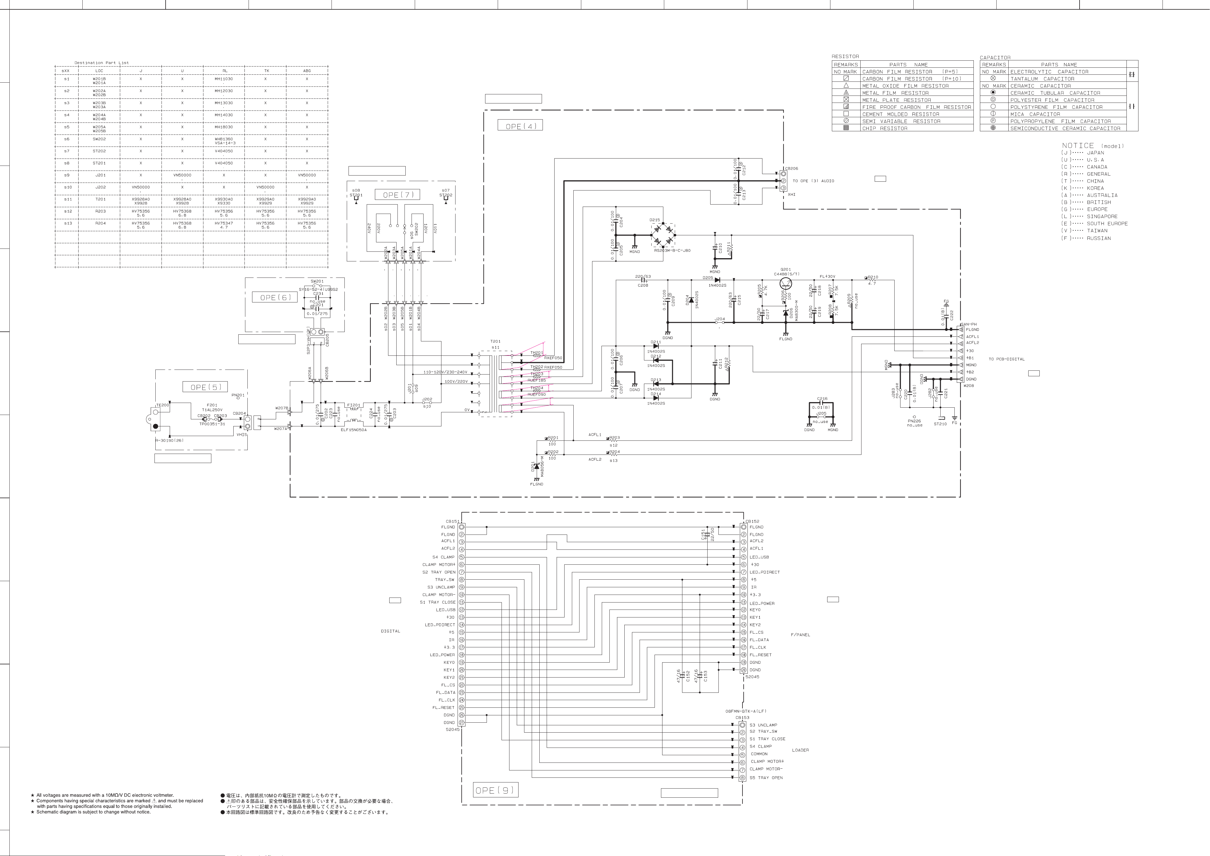
SCHEMATIC DIAGRAMS
DIGITAL 1/2
A-1
A-2
3.3
0
3.4
2.0
2.6
2.0
2.6
3.3
2.6
0
0
0.8
0
1.9
0
0
3.3
1.7
1.7
1.7
1.8
1.800
3.2
3.2
3.2
3.2
3.3
1.6
1.601.7
1.7
3.3
1.7
1.801.9
2.0
3.3
3.2
3.2
3.3
3.4
0
3.4
0
1.9
3.4
3.4
0
0
0.8
3.4
0
3.3
000
0
0
0
1.9
0
1.7
1.7
1.7
1.7
3.2
3.2
3.3
1.7
3.3
3.3
1.8
1.8
0
1.8
1.8
3.3
1.7
1.8
0
1.7
1.5
0
0
3.3
1.9
1.7
2.4
1.7
1.7
1.7
0
7.9
1.7
3.6
3.7
3.3
4.0
7.9
1.7
3.3
3.3
0
0
0
3.5
3.7
3.7
3.6
1.5
5.8
0
1.2
3.3
1.0
1.7
0
0
1.7
3.3
1.7
0
1.9
1.9
0.2
2.4
2.0
1.8
1.3
1.8
3.3
1.2
1.3
1.7
1.7
0.9
1.5
1.5
0
1.2
1.8
1.9
1.9
1.9
1.9
1.9
1.8
1.7
3.3
3.3
1.8
1.8
1.7
1.7
1.7
3.2
3.2
3.2
1.7
1.7
1.7
1.4
3.2
3.301.7
1.8
1.8
1.8
1.8
1.7
0
0
1.6
1.5
1.6
1.6
1.7
1.7
1.7
2.0
1.9
1.8
1.6
0
3.3
3.3
1.6
1.6
0
1.3
1.7
1.7
1.7
1.7
1.7
3.4
3.43.4
1.7
0
0
0
3.3
3.3
1.7
0
1.7
3.3
1.703.3
3.3
3.303.3
3.3
1.6
1.7
0
0
3.303.303.3
3.3
3.3
3.3
0
1.6
3.3
3.3
1.6
3.3
0
CD IN
DIGITAL OUT
USB IN
AUDIO OUT
R820
J811
D803
MN6627971YA
USB
MICROPROCESSOR
CD CONTROLLER
ACTUATOR DRIVER
SDRAM
POINT A-1 XL601 (Pin 109 of IC602) POINT A-2 XL603 (Pin 12 of IC604)
VDD
A3
A2
A1
A0
A10/AP
BA
CS
RAS
CAS
WE
LDQM
DQ7
V
SSQ
DQ2
V
DDQ
DQ4
V
SSQ
DQ6
V
DDQ
DQ1
DQ5
DQ3
DQ0
VDD
VSS
A4
A5
A6
A7
A8
A9
N.C
CKE
CLK
UDQM
N.C/RFU
DQ8
V
SSQ
DQ13
V
DDQ
DQ11
V
SSQ
DQ9
V
DDQ
DQ14
DQ10
DQ12
DQ15
V
SS
25
24
23
22
21
20
19
18
17
16
15
14
13
12
11
10
9
8
7
6
5
4
3
2
1
26
27
28
29
30
31
32
33
34
35
36
37
38
39
40
41
42
43
44
45
46
47
48
49
50
IC605: M12L16161A-7TG
512 K x 16-bit x 2 banks synchronous DRAM
Bank Select
Data Input Register
Column Decoder
Latency & Burst Length
Programming Register
Timing Register
LWCB R
LDQM
DQi
LDQM
LWE
LCAS
LWELCBRLRAS
CLK CKE CS RAS CAS WE L(U)DQM
LCKE
LCBR
LRAS
ADD
CLK
512K x 16
512K x 16
Address Register
Row DecoderCol. Buffer
Sense AMP
Output Buffer I/O Control
Row Buffer
Refresh Counter
VIN
4
EN
1
2
5
GATE
CONTROL
UVLO
THERMAL
SHUTDOWN
CURRENT
LIMIT
FLAG
DELAY
V
OUT
3 FLG
GND
IC606: R5523N001A-TR-F
High side switch IC
IC604: MN103SFB5KYAA
USB microprocessor
TIMER
INTERRUPT
CONTROL
WDTx1
35 Factor
INTERFACE
MEMORY
8 KB
256 KByte
8 KByte
8-bit x 4
16-bit x 2
DMA 4 CH
USB
ROM
32 bit
MICRO-
PROCESSOR
CORE
FLASH
MEMORY
DATA
RAM
SIF
x 2
I2C
x 1
34 pcs (3 V type)
8 pcs (5 V type)
CLOCK &
SYSTEM control
I/O port
to OPERATION (8)_CB162
(Writing port)
To Loader ass’y
Page 41
H4
To Loader ass’y

IC304
IC305
CB301
CB300
IC311
IC302
IC300
IC303
IC306
IC307
IC309
IC310
IC310
CB304
CB303
IC308
IC308
IC308
IC308
IC310
A
1
2
3
4
5
6
7
8
9
10
BCDEFGH I J K
L MN
CD-S700
40
DIGITAL 2/2
A-3
B-2
B-1
4.9
4.2
4.9
4.9
3.3
3.3
0
4.2
4.2
0
4.2
0
20.0
20.0
4.901.0
10.0
7.9
7.9
7.9
7.4
7.4
0
0
7.4
0
0
0
3.3
3.3
0
1.7
4.9
1.7
0
3.3
3.3
3.3
3.3
3.3
3.3
0
0
7.9
7.9
0.6
0.8
0.8
0
1.0
0
0.4
0.6
0
0
0
7.9
7.9
0.6
3.3
3.3
0
0.8
0.8
0.6
0
3.1
3.3
3.3
0
0
3.3
3.3
3.3
0
0
3.3
3.3
4.9
4.9
4.9
0
3.3
0
4.9
0
0
0
3.3
3.3
3.3
3.3
0
0
0
3.3
1.701.5
3.3
3.3
3.3
000
0
3.3
0
3.3
3.3
3.3
3.3
0
0
3.30003.2
3.2
3.3
3.3
3.3
3.3
0
1.6
3.3
3.3
0
3.3
3.3
3.3
0
0
0
3.3
3.3
0
4.9
0
2.5
2.5
0
2.5
5.0
2.5
2.5
0
5.0
2.5
0
20.0
20.0
7.901.1
20.0
1
2
DIGITAL OUT
AUDIO OUT
C816
BD5229G–TR
J812
J810
C817
2200P(B)
MICROPROCESSOR
CLAMP DRIVER
LOADING DRIVER
BUFFER AMP.
LEVEL
SHIFTER
OPTICAL
COAXIAL
DIGITAL OUT
Vref
Vout
GND
V
DD
N.C.
N.C.
4
1
2
3
5
–
+
IC307: BD4829G-TR
Voltage detector IC
IC305, 306: LB1641
Motor driver
INPUT LOGIC
IN 1
IN 2
VZ
P1
P2
OUT 1
OUT 2
VCC 2
VCC 1
GND
PRE DRIVER
1
3281097
4
6
5
IC304: M30302FAPFP
Single-chip 16-bit microprocessor
Timer (16-bit)
Peripheral function
Input (timer A) x3
Output (timer B) x3
Watchdog timer
(15-bit)
DMAC
(2-channel)
A/D converter
(10-bit X 18-channel
)
System clock generator
X
IN-XOUT
X
CIN-XCOUT
M16C/60 series
Microprocessor core
Port P08Port P18Port P28Port P38Port P48Port P58Port P6
8
8
R0LR0H
R1H R1L
R2
R3
ISP
USP
INTB
SB
CRC arithmetic circuit (CCITT)
(Polynomial : X
16+X12+X5
+1)
Multiplier
7
8
Port P9
8
Port P10
Port P8_5
Port P8
Port P7
Memory
ROM
(Note 1)
RAM
(Note 2)
FB
A1
FB
A1
A0
FLG
PC
UART or clock synchronous type
serial I/O
(3-channel)
Note 1: ROM contents var y depending on types.
RAM contents vary depending on types.
Note 2:
VDD
CE
Pin No.
1
2, 5
3
4
6
Symbol
V
OUT
GND
CE
NC
V
DD
Description
Output Pin of Voltage Regulator
Ground Pin
Chip Enable Pin
No Connection
Input Pin
Vref
61
3 2,5
Current Limit
VOUT
GND
IC303: R1172S331B-E2-F
CMOS-based positive-voltage regulator IC
IC308: TC74VHCT08AFT
Quad 2-input AND gate
Vcc14
4B
4A
4Y
3B
3A
3Y
1A 1
2
3
13
12
11
10
9
8
4
5
6
7
1B
1Y
2A
2B
2Y
GND
1
3
2
5
4
GND
V
CC
IC309: TS7ST00F
2-input NAND gate
IN A
IN B
OUT Y
IC310: TC7WU04F
Triple inverter
1
2
3
4
8
7
6
5
1A
3Y
2A
GND
V
CC
1Y
3A
2Y
VDD
CE
Pin No.
1
2
3
4
5
6
Symbol
V
OUT
GND
CE
NC
V
DD
Description
Output Pin of Voltage Regulator
Ground Pin
GND Ground Pin
Chip Enable Pin (“H” Active)
No Connection
Input Pin
Vref
16
2,54
Current Limit
VOUT
GND
IC311: RP131S501D-E2-F
Voltage regulator
POINT B-1 B-2 1 / Pin2, 2 / Pin1 of IC307
12 pin
1 pin
2 pin
1 pin
2
1
2
AC cable ON AC cable OFF AC cable OFF
POINT A-3 XL300 (Pin 13 of IC304)
OSC
PWM COMP DRIVER
STBY
STBY
OUT
INV
GND
VCC
TSD
OCP
Error AMP
SS
CTL
LOGIC
IC300, 302: BD9870FPS-E2
High stand voltage 1 channel step-down switching regulator
VREF
1
5
FIN
4
2
to OPERATION (4)_W208
Page 42
L5
to OPERATION (3)_W2
Page 41
G6
to OPERATION (9)_CB151
Writing port
Page 42
F8
To Loader ass’y

CB101
IC802
W2
CB162
CB161
W101BW101A
CB1
IC4
IC2
IC2
IC1
A
1
2
3
4
5
6
7
8
9
10
BCDEFGH I J K
L MN
CD-S700
41
OPERATION 1/2
5.5
0.6
0.8
0
0
4.9
4.9
4.9
3.5
5.1
30.3
0.8
0.8
5.5
0.6
30.3
30.3
5.7
0
30.3
5.1
5.7
3.4
3.4
4.9
3.3
0
3.3
3.4
0
0
4.9
3.5
0
3.3
0
1.9
0
0
0.8
16.10
14.8
16.1
3.9
3.7
3.9
-11.6
3.7
5.8
16.2
16.2
4.8
4.8
5.8
16.2
16.2
-12.9
-12.9
-11.7
11.5
0
3.0
0
0.7
0.7
0.6
0.6
0
11.5
-11.6
-11.6
-11.6
-11.6
0
-11.6
0
0
-11.6
0
0
-11.6
-11.5
-11.6
-11.5
-11.6
0
0
-11.6
0
1.7
1.7
0.901.6
0
0
4.7
0
1.1
1.1
2.2
3.3
3.0
3.3
3.3
3.3
000
0
4.7
4.7
0
1.1
1.1
0
4.7
-11.6
0
5.8
-16.2
0
16.2
-16.2
-16.2
0
16.2
-12.9
0
16.0
16.2
0
16.1
16.10
AUDIO OUT
330
s16
s16
s18
s17
s18
s17
330
100/50
100/50
330
1000/16
GSR
D/A CONVERTER
OPERATION (1)
ANALOG OUT
OPERATION (8)
OPERATION (3)
OPERATION (2)
USB
POWER
indicator
PURE DIRECT
indicator
USB indicator
Power Supply
DSDL
SCK
Advanced
Segment
DAC
Modulator
V
OUT
L+
V
OUT
L
Bias
and
Vref
V
CC
F
V
DD
AGNDR
V
CC
R
AGNDL
AGNDF
D/S and Filter
8
Oversampling
Digital
Filter
and
Function
Control
Audio
Data Input
I/F
PLRCK
PBCK
PDATA
MDI
MC
MS
AGNDC
V
CC
C
DGND
Current
Segment
DAC
and
I/V Buffer
V
COM
Function
Control
I/F
Zero
Detect
ZEROL
ZEROR
System
Clock
Manager
DSDR
DBCK
V
CC
L
V
OUT
R
V
OUT
R+
D/S and Filter
Current
Segment
DAC
and
I/V Buffer
RST
1
2
3
4
5
6
7
8
9
10
11
12
13
14
28
27
26
25
24
23
22
21
20
19
18
17
16
15
PLRCK
PBCK
PDATA
DBCK
SCK
RST
V
DD
DGND
AGNDF
V
CC
R
AGNDR
V
OUT
R
V
OUT
R+
V
COM
MS
MC
MDI
DSDL
DSDR
ZEROL
ZEROR
V
CC
F
V
CC
L
AGNDL
V
OUT
L
V
OUT
L+
AGNDC
V
CC
C
IC1: DSD1791DBR
24-bit, 192 kHz sampling, advanced segment, audio stereo digital-to-analog converter
IC4: PQ033ES3MXP
Low power loss regulator
3
DC input (Vin)
1
DC output (Vo)
2
GND
IC
IC2: OP275GSR
Dual bipolar/JFET, audio operational amplifier
OUT A
-IN A
V-
V+
OUT B
1
2
3
4
5
+IN A -IN B
+IN B
6
7
8
1
3
2
5
4
GND
AB Y
V
CC
IC802: TC7SH08F
2-input AND gate
IN A
IN B
OUT Y
LL L
LH L
HL L
HH H
to DIGITAL_CB301
Page 40
D7
to OPERATION (4)_CB206
Page 42
J3
to DIGITAL_CB609
Page 39
M6
to OPERATION (9)_CB152
Page 42
I7
CB151
CB153
CB152
W208
CB206
W202A
W203A
W205A
W201A
W204A
W202B
CB205
W207B
CB204
W207A
W206B
W206A
W203B
W205B
W201B
W204B
A
1
2
3
4
5
6
7
8
9
10
BCDEFGH I J K
L MN
CD-S700
42
OPERATION 2/2
0
29.6
10.0
29.6
20.0
20.0
39.1
20.0
10.0
20.0
10.0
0
10.0
5.4
0
0
30.3
31.0
39.1
31.0
0
10.0
10.0
AC27.4
AC15.9
AC16.1
AC4.6
s16
s17
s18
IC2
C27
C28
C34
C33
XV763A0
OP275GSR
WJ60860
560P/100
WJ60990
6800P/100
YA089A0
LME49723MA
WE10140
560P/100
WE10270
6800P/100
YA089A0
LME49723MA
WE10140
560P/100
WE10140
560P/100
YA089A0
LME49723MA
WE10140
560P/100
WE10140
560P/100
YA089A0
LME49723MA
WE10140
560P/100
WE10140
560P/100
2200/35
1P22K
0.01(B)
4700/35
1P22K
OPERATION (7)
OPERATION (6)
OPERATION (5)
OPERATION (9)
OPERATION (4)
POWER ON/OFF
AC IN
R, L models
VOLTAGE
SELECTOR
to OPERATION (1)_CB101
Page 41
A2
to DIGITAL_CB303
Page 40
M4
to DIGITAL_CB300
Page 40
B5
to OPERATION (3)_CB1
Page 41
G10
To Loader ass
’y

■ REPLACEMENT PARTS LIST
• ELECTRICAL COMPONENT PARTS
WARNING
● Components having special characteristics are marked ⚠ and must be replaced with parts having specifications
equal to those originally installed.
● The chip resistor is not supplied as a replacement part.
* When a chip resistor is necessary, use the following part.
AAX60720: CHIP RESISTOR SAMPLE BOOK
● ⚠印のある部分は、安全確保部品を示しています。部品の交換が必要な場合、パーツリストに記載されている部品を使用し
てください。
● チップ抵抗はサービス部品として供給しません。
※ チップ抵抗が必要な場合は、下記の部品をご利用ください。
AAX60720:CHIPRESISTORSAMPLEBOOK
● 部品価格ランクは、予告なく変更することがあります。
ABBREVIATIONS IN THIS LIST ARE AS FOLLOWS:
C.A.EL.CHP : CHIP ALUMI.ELECTROLYTIC CAP
C.CE : CERAMIC CAP
C.CE.ARRAY : CERAMIC CAP ARRAY
C.CE.CHP : CHIP CERAMIC CAP
C.CE.ML : MULTILAYER CERAMIC CAP
C.CE.M.CHP : CHIP MULTILAYER CERAMIC CAP
C.CE.SAFTY : RECOGNIZED CERAMIC CAP
C.CE.TUBLR : CERAMIC TUBULAR CAP
C.CE.SMI : SEMI CONDUCTIVE CERAMIC CAP
C.EL : ELECTROLYTIC CAP
C.MICA : MICA CAP
C.ML.FLM : MULTILAYER FILM CAP
C.MP : METALLIZED PAPER CAP
C.MYLAR : MYLAR FILM CAP
C.MYLAR.ML : MULTILAYER MYLAR FILM CAP
C.PAPER : PAPER CAPACITOR
C.PLS : POLYSTYRENE FILM CAP
C.POL : POLYESTER FILM CAP
C.POLY : POLYETHYLENE FILM CAP
C.PP : POLYPROPYLENE FILM CAP
C.TNTL : TANTALUM CAP
C.TNTL.CHP : CHIP TANTALUM CAP
C.TRIM : TRIMMER CAP
CN : CONNECTOR
CN.BS.PIN : CONNECTOR,BASE PIN
CN.CANNON : CONNECTOR,CANNON
CN.DIN : CONNECTOR,DIN
CN.FLAT : CONNECTOR,FLAT CABLE
CN.POST : CONNECTOR,BASE POST
COIL.MX.AM : COIL,AM MIX
COIL.AT.FM : COIL,FM ANTENNA
COIL.DT.FM : COIL,FM DETECT
COIL.MX.FM : COIL,FM MIX
COIL,OUTPT : OUTPUT COIL
DIOD.ARRAY : DIODE ARRAY
DIODE.BRG : DIODE BRIDGE
DIODE.CHP : CHIP DIODE
DIODE.VAR : VARACTOR DIODE
DIOD.Z.CHP : CHIP ZENER DIODE
DIODE.ZENR : ZENER DIODE
DSCR.CE : CERAMIC DISCRIMINATOR
FER.BEAD : FERRITE BEADS
FER.CORE : FERRITE CORE
FET.CHP : CHIP FET
FL.DSPLY : FLUORESCENT DISPLAY
FLTR.CE : CERAMIC FILTER
FLTR.COMB : COMB FILTER MODULE
FLTR.LC.RF : LC FILTER,EMI
GND.MTL : GROUND PLATE
GND.TERM : GROUND TERMINAL
HOLDER.FUS : FUSE HOLDER
IC.PRTCT : IC PROTECTOR
JUMPER.CN : JUMPER CONNECTOR
JUMPER.TST : JUMPER,TEST POINT
L.DTCT : LIGHT DETECTING MODULE
CD-S700
L.EMIT : LIGHT EMITTING MODULE
LED.DSPLY : LED DISPLAY
LED.INFRD : LED,INFRARED
MODUL.RF : MODULATOR,RF
PHOT.CPL : PHOTO COUPLER
PHOT.INTR : PHOTO INTERRUPTER
PHOT.RFLCT : PHOTO REFLECTOR
PIN.TEST : PIN,TEST POINT
PLST.RIVET : PLASTIC RIVET
R.ARRAY : RESISTOR ARRAY
R.CAR. : CARBON RESISTOR
R.CAR.CHP : CHIP RESISTOR
R.CAR.FP : FLAME PROOF CARBON RESISTOR
R.FUS : FUSABLE RESISTOR
R.MTL.CHP : CHIP METAL FILM RESISTOR
R.MTL.FLM : METAL FILM RESISTOR
R.MTL.OXD : METAL OXIDE FILM RESISTOR
R.MTL.PLAT : METAL PLATE RESISTOR
RSNR.CE : CERAMIC RESONATOR
RSNR.CRYS : CRYSTAL RESONATOR
R.TW.CEM : TWIN CEMENT FIXED RESISTOR
R.CEMENT : CEMENT RESISTOR
SCR.BND.HD : BIND HEAD B-TIGHT SCREW
SCR.BW.HD : BW HEAD TAPPING SCREW
SCR.CUP : CUP TIGHT SCREW
SCR.TERM : SCREW TERMINAL
SCR.TR : SCREW,TRANSISTOR
SUPRT.PCB : SUPPORT,P.C.B.
SURG.PRTCT : SURGE PROTECTOR
SW.TACT : TACT SWITCH
SW.LEAF : LEAF SWITCH
SW.LEVER : LEVER SWITCH
SW.MICRO : MICRO SWITCH
SW.PUSH : PUSH SWITCH
SW.RT.ENC : ROTARY ENCODER
SW.RT.MTR : ROTARY SWITCH WITH MOTOR
SW.RT : ROTARY SWITCH
SW.SLIDE : SLIDE SWITCH
TERM.SP : SPEAKER TERMINAL
TERM.WRAP : WRAPPING TERMINAL
THRMST.CHP : CHIP THERMISTOR
TR.CHP : CHIP TRANSISTOR
TR.DGT : DIGITAL TRANSISTOR
TR.DGT.CHP : CHIP DIGITAL TRANSISTOR
TRANS : TRANSFORMER
TRANS.PULS : PULSE TRANSFORMER
TRANS.PWR : POWER TRANSFORMER ASS’Y
TUNER.AM : TUNER PACK,AM
TUNER.FM : TUNER PACK,FM
TUNER.PK : FRONT-ENDTUNER PACK
VR : ROTARY POTENTIOMETER
VR.MTR : POTENTIOMETER WITH MOTOR
VR.SW : POTENTIOMETER WITH ROTARY SW
VR.SLIDE : SLIDE POTENTIOMETER
VR.TRIM : TRIMMER POTENTIOMETER
CD-S700
43

CD-S700
P.C.B. DIGITAL
Ref No. Part No. Description Remarks Markets
* WQ026500 P.C.B. DIGITAL PCB DIGITAL
CB300 VB390400 CN.BS.PIN 8P ベースピン 01
CB301 VE352600 CN.BS.PIN 14P コネクタベースポスト 01
CB302 VB389800 CN.BS.PIN 2P ベースピン 01
CB303 VQ045600 CN.BS.PIN 27P SE FFCコネクター 03
CB304 VP682300 CN.BS.PIN 8P FFCコネクター 01
CB602 VB390200 CN.BS.PIN 6P コネクタベースポスト 01
CB604 V2731000 CN.FMN 16P FMN コネクター 02
CB608 VB390100 CN.BS.PIN 5P ベースピン 01
CB609 VB858400 CN.BS.PIN 5P ベースピン 01
* C300 WM489900 C.CE.CHP 10uF 35V チップセラコン
* C302 WM489900 C.CE.CHP 10uF 35V チップセラコン
* C303 UR259100 C.EL 1000uF 35V ケミコン
C304-305 US064100 C.CE.CHP 0.01uF 50V B チップセラコン 01
* C306 WG782400 C.EL 22uF 50V ケミコン
C307 WK004400 C.CE.M.CHP 10uF 16V チップ積層セラコン 01
C309 WK004400 C.CE.M.CHP 10uF 16V チップ積層セラコン 01
C313 US064100 C.CE.CHP 0.01uF 50V B チップセラコン 01
C315 WG251600 C.CE.CHP 4.7uF 6.3V チップセラコン 01
* C317 WP882000 C.CE.CHP 10uF 6.3V チップセラコン
C318-320 US135100 C.CE.CHP 0.1uF 16V チップセラコン 01
C321-322 US126100 C.CE.CHP 1uF 10V チップセラコン 01
C323 US064100 C.CE.CHP 0.01uF 50V B チップセラコン 01
C324 UF418100 C.EL.CHP 100uF 6.3V チップケミコン 01
C325 US061330 C.CE.CHP 33pF 50V B チップセラコン 01
C326-327 US064100 C.CE.CHP 0.01uF 50V B チップセラコン 01
C328-330 US135100 C.CE.CHP 0.1uF 16V チップセラコン 01
C331 UF438100 C.EL.CHP 100uF 16V チップケミコン 01
C332-333 US135100 C.CE.CHP 0.1uF 16V チップセラコン 01
C334 US064100 C.CE.CHP 0.01uF 50V B チップセラコン 01
C335 UF438100 C.EL.CHP 100uF 16V チップケミコン 01
C336 US135100 C.CE.CHP 0.1uF 16V チップセラコン 01
C337-338 US064100 C.CE.CHP 0.01uF 50V B チップセラコン 01
C339 US061330 C.CE.CHP 33pF 50V B チップセラコン 01
* C340 UF437330 C.EL.CHP 33uF 16V チップケミコン
C341 US064100 C.CE.CHP 0.01uF 50V B チップセラコン 01
C342 US062330 C.CE.CHP 330pF 50V B チップセラコン 01
C343-344 US061330 C.CE.CHP 33pF 50V B チップセラコン 01
C345 US064100 C.CE.CHP 0.01uF 50V B チップセラコン 01
C346 US061330 C.CE.CHP 33pF 50V B チップセラコン 01
C347 US064150 C.CE.CHP 0.015uF 50V B チップセラコン 01
C349-350 US064100 C.CE.CHP 0.01uF 50V B チップセラコン 01
C351 US062330 C.CE.CHP 330pF 50V B チップセラコン 01
C352-353 US064100 C.CE.CHP 0.01uF 50V B チップセラコン 01
CD-S700
44
C355-356 US064100 C.CE.CHP 0.01uF 50V B チップセラコン 01
C357-358 WC890400 C.EL.CHP 100uF 6.3V チップケミコン 01
* C363 UR259100 C.EL 1000uF 35V ケミコン
C370 US064100 C.CE.CHP 0.01uF 50V B チップセラコン 01
* C380-381 WM489900 C.CE.CHP 10uF 35V チップセラコン
C382-383 WK004400 C.CE.M.CHP 10uF 16V チップ積層セラコン 01
C384 WF456400 C.CE.M.CHP 4.7uF 16V チップ積層セラコン 01
* C385 WP882000 C.CE.CHP 10uF 6.3V チップセラコン
C601 US135100 C.CE.CHP 0.1uF 16V チップセラコン 01
C602-603 UF418100 C.EL.CHP 100uF 6.3V チップケミコン 01
C605 US063100 C.CE.CHP 1000pF 50V B チップセラコン 01
C606 WC892500 C.EL.CHP 470uF 16V チップケミコン
C607 UF437470 C.EL.CHP 47uF 16V チップケミコン 01
✻ New Parts
*新規部品
部 品 名
ランク

P.C.B. DIGITAL
CD-S700
Ref No. Part No. Description Remarks Markets
C608 US135100 C.CE.CHP 0.1uF 16V チップセラコン 01
C610 WC892500 C.EL.CHP 470uF 16V チップケミコン
C611 US135100 C.CE.CHP 0.1uF 16V チップセラコン 01
C612-613 US063220 C.CE.CHP 2200pF 50V B チップセラコン 01
C614-615 US063150 C.CE.CHP 1500pF 50V B チップセラコン 01
C616 UF438100 C.EL.CHP 100uF 16V チップケミコン 01
C617 US135100 C.CE.CHP 0.1uF 16V チップセラコン 01
C619 US135220 C.CE.CHP 0.22uF 16V チップセラコン 01
C620 US135100 C.CE.CHP 0.1uF 16V チップセラコン 01
C621 US062680 C.CE.CHP 680pF 50V B チップセラコン 01
C622 US044220 C.CE.CHP 0.022uF 25V B チップセラコン 01
C623 US135100 C.CE.CHP 0.1uF 16V チップセラコン 01
C624 US063100 C.CE.CHP 1000pF 50V B チップセラコン 01
C625 US034820 C.CE.CHP 0.082uF 16V K チップセラコン 01
C626 US063100 C.CE.CHP 1000pF 50V B チップセラコン 01
C627 US135330 C.CE.CHP 0.33uF 16V チップセラコン 01
C628 UF418100 C.EL.CHP 100uF 6.3V チップケミコン 01
C629 WG251600 C.CE.CHP 4.7uF 6.3V チップセラコン 01
C630 UF418100 C.EL.CHP 100uF 6.3V チップケミコン 01
C631 US044220 C.CE.CHP 0.022uF 25V B チップセラコン 01
C632 US063330 C.CE.CHP 3300pF 50V B チップセラコン 01
C633 US135330 C.CE.CHP 0.33uF 16V チップセラコン 01
C634 US135100 C.CE.CHP 0.1uF 16V チップセラコン 01
C635 US135150 C.CE.CHP 0.15uF 16V チップセラコン 01
C642 US135100 C.CE.CHP 0.1uF 16V チップセラコン 01
* C643 UF417470 C.EL.CHP 47uF 6.3V チップケミコン
C644 US135100 C.CE.CHP 0.1uF 16V チップセラコン 01
C645 UF418100 C.EL.CHP 100uF 6.3V チップケミコン 01
C647 US135100 C.CE.CHP 0.1uF 16V チップセラコン 01
C648 UF418100 C.EL.CHP 100uF 6.3V チップケミコン 01
C649 US135100 C.CE.CHP 0.1uF 16V チップセラコン 01
C650 UF418100 C.EL.CHP 100uF 6.3V チップケミコン 01
C651 US135100 C.CE.CHP 0.1uF 16V チップセラコン 01
C652 WC890400 C.EL.CHP 100uF 6.3V チップケミコン 01
* C653 WP882000 C.CE.CHP 10uF 6.3V チップセラコン
C654 US135100 C.CE.CHP 0.1uF 16V チップセラコン 01
C656 US135100 C.CE.CHP 0.1uF 16V チップセラコン 01
* C658 WP882000 C.CE.CHP 10uF 6.3V チップセラコン
C659-660 US135100 C.CE.CHP 0.1uF 16V チップセラコン 01
* C661 WP882000 C.CE.CHP 10uF 6.3V チップセラコン
C662 US135100 C.CE.CHP 0.1uF 16V チップセラコン 01
* C663 WP882000 C.CE.CHP 10uF 6.3V チップセラコン
C664 US063100 C.CE.CHP 1000pF 50V B チップセラコン 01
C665-669 US135100 C.CE.CHP 0.1uF 16V チップセラコン 01
C670 US063100 C.CE.CHP 1000pF 50V B チップセラコン 01
C671-672 US135100 C.CE.CHP 0.1uF 16V チップセラコン 01
C673 US063100 C.CE.CHP 1000pF 50V B チップセラコン 01
C674-676 US135100 C.CE.CHP 0.1uF 16V チップセラコン 01
C677-678 US063100 C.CE.CHP 1000pF 50V B チップセラコン 01
C679 US135100 C.CE.CHP 0.1uF 16V チップセラコン 01
* C680-682 UF417470 C.EL.CHP 47uF 6.3V チップケミコン
C683-684 US135100 C.CE.CHP 0.1uF 16V チップセラコン 01
C685 US063100 C.CE.CHP 1000pF 50V B チップセラコン 01
C686 UF418100 C.EL.CHP 100uF 6.3V チップケミコン 01
C687-688 US135100 C.CE.CHP 0.1uF 16V チップセラコン 01
C697 WJ881200 C.CE.CHP 1uF 16V チップセラコン 01
C698 UF418100 C.EL.CHP 100uF 6.3V チップケミコン 01
✻ New Parts
*新規部品
部 品 名
ランク
CD-S700
45

CD-S700
P.C.B. DIGITAL
Ref No. Part No. Description Remarks Markets
C703 US135100 C.CE.CHP 0.1uF 16V チップセラコン 01
C705 US135100 C.CE.CHP 0.1uF 16V チップセラコン 01
* C708 WP882000 C.CE.CHP 10uF 6.3V チップセラコン
C709-714 US063100 C.CE.CHP 1000pF 50V B チップセラコン 01
* C716-717 WP882000 C.CE.CHP 10uF 6.3V チップセラコン
C718 US135100 C.CE.CHP 0.1uF 16V チップセラコン 01
C721-722 US064100 C.CE.CHP 0.01uF 50V B チップセラコン 01
C723-724 US061180 C.CE.CHP 18pF 50V B チップセラコン 01
C816 WK004400 C.CE.M.CHP 10uF 16V チップ積層セラコン 01
C817 US063220 C.CE.CHP 2200pF 50V B チップセラコン 01
* D300 WP292300 DIODE RB050LA-40TR TP ダイオード
* D302 WP292300 DIODE RB050LA-40TR TP ダイオード
D303 WM180900 DIODE FM203-W TE ダイオード 01
D304 VT332900 DIODE 1SS355 ダイオード 01
D306-307 VT332900 DIODE 1SS355 ダイオード 01
D308 VV220700 DIODE.SHOT RB501V-40 ショットキーダイオード 01
D309 VT332900 DIODE 1SS355 ダイオード 01
D310-311 VU992300 DIODE.ZENR MA8047-H 4.9V ツェナーダイオード 01
D312-313 VT332900 DIODE 1SS355 ダイオード 01
* D314 WM180900 DIODE FM203-W TE ダイオード 01
D317 VT332900 DIODE 1SS355 ダイオード 01
D601-602 VT332900 DIODE 1SS355 ダイオード 01
D603-604 VV220700 DIODE.SHOT RB501V-40 ショットキーダイオード 01
* F301-302 WQ151600 SW.POLY MINISMDC110F/24 ポリスィッチ
* IC300 X9850A00 IC BD9870FPS 電源IC
* IC302 X9850A00 IC BD9870FPS 電源IC
IC303 X8897A00 IC R1172S331B-E2-F 電源IC 03
IC304 X9278A00 IC.CPU M30302FAPFP CPU boot only IC CPU
IC305-306 XF494A00 IC LB1641 IC 03
* IC307 YA514A00 IC BD5229G-TR IC 02
IC308 X3586B00 IC TC74VHCT08AFT EL,K ロジックIC 01
IC309 X3904A00 IC TS7ST00F NAND ロジックIC 01
IC310 XN567A00 IC TC7WU04F INV IC 01
* IC311 YA137A00 IC RP131S501D-E2 電源IC
* IC601 X8685A00 IC AN41010A-VF ドライバーIC
* IC602 X9932A00 IC.CPU.CD MN66F27971 MASK ROM IC CPU
* IC604 X9911A00 IC.CPU.USB MN103SFB5KYAA written IC CPU
IC605 X5693B00 IC.MEMORY M12L16161A-7TG メモリIC 16M
IC606 X8096A00 IC R5523N001A-TR-F 電源IC 03
PJ300 V2283400 JACK.PIN 1P ピンジャック 04
Q300 VV556500 TR 2SA1037K Q,R,S トランジスタ 01
Q601 iB070900 TR 2SB709A P,Q,R,S トランジスタ 01
Q602 VV556500 TR 2SA1037K Q,R,S トランジスタ 01
R332 HV753220 R.CAR.FP 2.2 Ω 1/4W 不燃化カーボン抵抗 01
CD-S700
R361 HV753220 R.CAR.FP 2.2 Ω 1/4W 不燃化カーボン抵抗 01
U300 WH536900 CN.PHOTO.T 1P GP1FAV51TK0F 光ファイバー送信器 04
XL300 V8222200 RSNR.CE 10MHz CSTLS10M0 セラミック振動子 01
XL601 WB872100 RSNR.CRYS 16.9344MHz 水晶振動子 03
* XL603 WQ332600 RSNR.CE 12MHz セラミック発振子
部 品 名
ランク
46
✻ New Parts
*新規部品

P.C.B. OPERATION
CD-S700
Ref No. Part No. Description Remarks Markets
* WQ026900 P.C.B. OPERATION J * WQ027000 P.C.B. OPERATION U * WQ027100 P.C.B. OPERATION RL * WQ027200 P.C.B. OPERATION TK * WQ027300 P.C.B. OPERATION ABG
CB1 VL844700 CN.BS.PIN 3P ベース付ポスト 01
CB101 VQ045000 CN.BS.PIN 20P FFCコネクター 01
CB151 VQ047800 CN.BS.PIN 27P FFCコネクター 02
CB152 VQ047500 CN.BS.PIN 20P FFCコネクター 01
CB153 V6217800 CN.BS.PIN 8P TE FMN FFCコネクター 01
CB161 WG668100 CN.USB USB 4P SE USBコネクター 04
CB162 VB390100 CN.BS.PIN 5P ベースピン 01
CB202-203 WN103000 CLIP.FUSE TP00351-31 ヒューズクリップ 01
CB204 VG879900 CN.BS.PIN 2P ベースピン 01
CB205 VP245700 CN.BS.PIN VA 2P SE ベースツキポスト 01
CB206 LB918030 CN.BS.PIN 3P ベース付ポスト 01
C2 WE102900 C.PP 0.01uF 100V PPコン 01
C4 UR267470 C.EL 47uF 50V ケミコン 01
C5-6 WE102900 C.PP 0.01uF 100V PPコン
C8 US063100 C.CE.CHP 1000pF 50V B チップセラコン 01
C9 UR239100 C.EL 1000uF 16V ケミコン
C10 WE102900 C.PP 0.01uF 100V PPコン
C11 UR266330 C.EL 3.3uF 50V ケミコン
C12 WE102900 C.PP 0.01uF 100V PPコン
C13-14 UU238100 C.EL 100uF 16V ケミコン 01
* C15-16 WM113900 C.EL 3300uF 35V ケミコン
C18-19 US065100 C.CE.CHP 0.1uF 50V B チップセラコン 01
C21 WE102900 C.PP 0.01uF 100V PPコン
C22-25 UU267100 C.EL 10uF 50V ケミコン FW 01
* C27 WJ608600 C.PP 560pF 100V J PPコン 01
C27 WE101400 C.PP 560pF 100V URTKABGL PPコン 01
* C28 WJ608600 C.PP 560pF 100V J PPコン 01
C28 WE101400 C.PP 560pF 100V URTKABGL PPコン 01
C29-31 UU238100 C.EL 100uF 16V ケミコン 01
C32 US135330 C.CE.CHP 0.33uF 16V チップセラコン 01
* C33 WJ609900 C.PP 6800pF 100V J PPコン 01
C33 WE102700 C.PP 6800pF 100V URTKABGL PPコン 01
* C34 WJ609900 C.PP 6800pF 100V J PPコン 01
C34 WE102700 C.PP 6800pF 100V URTKABGL PPコン 01
C35-38 WE101300 C.PP 470pF 100V PPコン 01
C39 UU267100 C.EL 10uF 50V ケミコン FW 01
C40 US135330 C.CE.CHP 0.33uF 16V チップセラコン 01
C42 UU238100 C.EL 100uF 16V ケミコン 01
C44 UU238100 C.EL 100uF 16V ケミコン 01
* C53 WQ331800 C.EL 100uF 50V ケミコン 01
* C56 WQ331800 C.EL 100uF 50V ケミコン 01
C57-58 WE101700 C.PP 1000pF 100V PPコン
C60-61 US065100 C.CE.CHP 0.1uF 50V B チップセラコン 01
C62 WN165300 C.PP 0.01uF 100V PPコン 01
C101-102 US064100 C.CE.CHP 0.01uF 50V B チップセラコン 01
C103 US135100 C.CE.CHP 0.1uF 16V チップセラコン 01
C104 US062100 C.CE.CHP 100pF 50V B チップセラコン 01
C105 US135100 C.CE.CHP 0.1uF 16V チップセラコン 01
C106 US062100 C.CE.CHP 100pF 50V B チップセラコン 01
C107 WG780700 C.EL 47uF 16V ケミコン 01
C108 US062100 C.CE.CHP 100pF 50V B チップセラコン 01
C109 US065100 C.CE.CHP 0.1uF 50V B チップセラコン 01
✻ New Parts
*新規部品
部 品 名
PCB OPERATION
PCB OPERATION
PCB OPERATION
PCB OPERATION
PCB OPERATION
ランク
CD-S700
47

CD-S700
P.C.B. OPERATION
Ref No. Part No. Description Remarks Markets
C110-112 US064100 C.CE.CHP 0.01uF 50V B チップセラコン 01
C113 US126100 C.CE.CHP 1uF 10V チップセラコン 01
C114 US064100 C.CE.CHP 0.01uF 50V B チップセラコン 01
C116 US065100 C.CE.CHP 0.1uF 50V B チップセラコン 01
C117-120 US135100 C.CE.CHP 0.1uF 16V チップセラコン 01
C121 WG780700 C.EL 47uF 16V ケミコン 01
C122 US135100 C.CE.CHP 0.1uF 16V チップセラコン 01
* C151 WG782400 C.EL 22uF 50V ケミコン
C152-153 WG780700 C.EL 47uF 16V ケミコン 01
C162 US064100 C.CE.CHP 0.01uF 50V B チップセラコン 01
C201-203 V6185300 C.CE.SAFTY 0.01uF 275V 規格認定コンデンサ 01
C204-207 WE102900 C.PP 0.01uF 100V PPコン 01
* C208 UR278220 C.EL 220uF 63V ケミコン
C209 WN165300 C.PP 0.01uF 100V PPコン 01
* C210 UR059470 C.EL 4700uF 35V ケミコン
* C211 UR059220 C.EL 2200uF 35V ケミコン 03
C212-213 WE102900 C.PP 0.01uF 100V PPコン
* C215 UR278220 C.EL 220uF 63V ケミコン
C216 US064100 C.CE.CHP 0.01uF 50V B チップセラコン 01
C217-219 UR267220 C.EL 22uF 50V ケミコン 01
C220 US064100 C.CE.CHP 0.01uF 50V B チップセラコン 01
C222 US064100 C.CE.CHP 0.01uF 50V B チップセラコン 01
D1-2 VV307700 DIODE 1N4002S ダイオード 01
D3-4 VT332900 DIODE 1SS355 ダイオード 01
D5 VU991500 DIODE.ZENR MA8039-H 4V ツェナーダイオード 01
D6 WK870400 DIODE.BRG D4SBN20-7101 4A ダイオードブリッジ 04
D7 VV220700 DIODE.SHOT RB501V-40 ショットキーダイオード 01
D8 VU993400 DIODE.ZENR MA8062-M 6.2V ツェナーダイオード 01
D9-10 VU996600 DIODE.ZENR MA8130-M 13V ツェナーダイオード 01
D12 VV220700 DIODE.SHOT RB501V-40 ショットキーダイオード 01
D14-15 VV220700 DIODE.SHOT RB501V-40 ショットキーダイオード 01
D101 VU993000 DIODE.ZENR MA8056-M 5.6V ツェナーダイオード 01
D102-104 WA467800 LED SEL6910A-CD LED 01
D201 VU993000 DIODE.ZENR MA8056-M 5.6V ツェナーダイオード 01
D204-205 VV307700 DIODE 1N4002S ダイオード 01
D206 VU999900 DIODE.ZENR MA8300-M 30V ツェナーダイオード 01
D211-214 VV307700 DIODE 1N4002S ダイオード 01
D215 WH487300 DIODE.BRG RS203M 2.0A 200V ダイオードブリッジ 02
F201 KB001770 FUSE T1A 250V ヒューズ 02
IC1 X7947A00 IC DSD1791DBR D/Aコンバーター 07
IC2 XV763A00 IC OP275GSR OP AMP J アンプIC 05
IC2 YA089A00 IC LME49723MA URTKABGL アンプIC
IC4 X9430A00 IC PQ033ES3MXP 電源IC 03
IC802 X2656A00 IC TC7SH08F AND ロジックIC 01
CD-S700
48
JY11 WK849100 BUS.BAR.3P 3P バスバー3P 04
* PJ1-2 Wq070200 JACK.PIN 1P BLACK YKC21-391 ピンジャック
Q1 VV556500 TR 2SA1037K Q,R,S トランジスタ 01
Q2-4 VR043100 FET 2SK208 Y チップFET 01
Q5-6 WF691400 TR 2SD2014 トランジスタ 03
Q7 WF691300 TR 2SB1257 トランジスタ 03
Q14-17 VZ725900 TR 2SD1938F S,T トランジスタ 01
Q101-102 VV556400 TR 2SC2412K Q,R,S トランジスタ 01
Q103-105 VV655400 TR.DGT DTC114EKA デジタルトランジスタ 01
Q201 VP872700 TR 2SC4488 S,T トランジスタ 01
R12 V8071600 R.MTL.OXD 1K Ω 1W 金属被膜抵抗 01
* R18-19 V8071800 R.MTL.OXD 2.2K Ω 1W 酸化金属被膜抵抗
R20 HL006100 R.MTL.OXD 1K Ω 1/2W 酸化金属被膜抵抗
✻ New Parts
*新規部品
部 品 名
ランク

CD-S700
P.C.B. OPERATION
Ref No. Part No. Description Remarks Markets
* R21-22 HL004100 R.MTL.OXD 10 Ω 1/2W 酸化金属被膜抵抗
R27-29 HL005100 R.MTL.OXD 100 Ω 1/2W 酸化金属被膜抵抗
* R38 V8072300 R.MTL.OXD 10K Ω 1W 酸化金属被膜抵抗
R39 V8071300 R.MTL.FLM 470 Ω 1W 金属被膜抵抗
* R54-55 V8073000 R.MTL.OXD 100K Ω 1W 酸化金属被膜抵抗
R58 WA621700 R.MTL.FLM 270 Ω 1W 金属被膜抵抗
R61 WA621700 R.MTL.FLM 270 Ω 1W 金属被膜抵抗
R64 WA621700 R.MTL.FLM 270 Ω 1W 金属被膜抵抗
R67 WA621700 R.MTL.FLM 270 Ω 1W 金属被膜抵抗
* R68-69 WQ835800 R.MTL.FLM 100 Ω 1W 金属被膜抵抗 01
R201-202 HV755100 R.CAR.FP 100 Ω 1/4W 不燃化カーボン抵抗 01
R203 HV753560 R.CAR.FP 5.6 Ω 1/4W JRTKABGL 不燃化カーボン抵抗 01
R203 HV753680 R.CAR.FP 6.8 Ω 1/4W U 不燃化カーボン抵抗 01
R204 HV753560 R.CAR.FP 5.6 Ω 1/4W JTKABG 不燃化カーボン抵抗 01
R204 HV753680 R.CAR.FP 6.8 Ω 1/4W U 不燃化カーボン抵抗 01
R204 HV753470 R.CAR.FP 4.7 Ω 1/4W RL 不燃化カーボン抵抗 01
R205 HV756470 R.CAR.FP 4.7K Ω 1/4W 不燃化カーボン抵抗 01
R206 HV755100 R.CAR.FP 100 Ω 1/4W 不燃化カーボン抵抗 01
R210 HV753470 R.CAR.FP 4.7 Ω 1/4W 不燃化カーボン抵抗 01
* R211-212 V8072500 R.MTL.OXD 22K Ω 1W 酸化金属被膜抵抗
SW101-107 WD483100 SW.TACT SKRGAAD010 タクト SW 01
SW201 V8377400 SW.POWER SY16-52-4 パワースィッチ
* SW202 WH813600 VOLT.SELCT VSA-14-3 RL 電圧切替器
* T201 X9928A00 TRANS.PWR JUC CD-S700ML JU 電源トランス
* T201 X9929A00 TRANS.PWR TKAGBL CD-S700ML TKABG 電源トランス
* T201 X9930A00 TRANS.PWR R CD-S700ML RL 電源トランス
TE200 WB782600 AC INLET R-30190(26) ACインレット 2P
TH201-202 VV216100 PROTECTOR RXE050 0.50A 60V ポリスイッチ 03
TH203 VU847300 POSISTOR RUE185 1.85A 30V ポリスイッチ 03
TH204 VV457600 SW.POLY RUE090 0.90A 30V ポリスイッチ 02
U101 WH981800 L.DTCT GP1UE261RKVF リモコン受光ユニット 02
V101 WK835500 FL.DSPLY 13-ST-81GINK 螢光表示管 11
WM164600 SHEET シートFL 01
V6203300 SPACER スペーサーFL 01
✻ New Parts
*新規部品
部 品 名
ランク
Value 1/4W Type Part No. 1/6W Type Part No.
1.0 Ω
1.8 Ω
2.2 Ω
3.3 Ω
4.7 Ω
5.6 Ω
10 Ω
15 Ω
22 Ω
27 Ω
33 Ω
39 Ω
47 Ω
56 Ω
68 Ω
75 Ω
82 Ω
91 Ω
100 Ω
110 Ω
120 Ω
150 Ω
160 Ω
180 Ω
200 Ω
220 Ω
270 Ω
330 Ω
390 Ω
430 Ω
470 Ω
510 Ω
560 Ω
680 Ω
820 Ω
910 Ω
1.0 k
1.2 kΩ
1.5 kΩ
1.8 kΩ
2.0 kΩ
2.2 kΩ
2.4 kΩ
2.7 kΩ
3.0 kΩ
3.3 kΩ
3.6 kΩ
3.9 kΩ
4.7 kΩ
5.1 kΩ
5.6 kΩ
6.8 kΩ
8.2 kΩ
9.1 kΩ
10 kΩ HF45 7100 HF45 7100
: Not available
❊
HJ35
3100
HJ35
3180 ✻
HJ35
3220
HJ35
3330
HJ35
3470
HJ35
3560
HF45
4100
HJ35
4150
HF45
4220
HJ35
4270
HF45
4330
HJ35
4470
HF45
4470
HF45
4560
HF45
4680
HF45
4750
HF45
4820
HF45
4910
HF45
5100
HJ35
5110
HF45
5120
HF45
5150
HJ35
5160 ✻
HF45
5180
HF45
5200
HF45
5220
HF45
5270
HF45
5330
HF45
5390
HF45
5430
HF45
5470
HF45
5510
HF45
5560
HF45
5680
HF45
5820
HF45
5910
HF45
6100
HF45
6120
HF45
6150
HF45
6180
HJ35
6200
HF45
6220
HJ35
6240
HF45
6270
HF45
6300
HF45
6330
HJ35
6360
HF45
6390
HF45
6470
HF45
6510
HF45
6560
HF45
6680
HF45
6820
HF45
6910
Carbon Resistors
HF85
3100
HF85
3220
HF85
3330
HF85
3470
HF85
3560
HF45
4100
HF85
4150
HF45
4220
HF85
4270
HF45
4330
HF85
4390
HF45
4470
HF45
4560
HF45
4680
HF45
4750
HF45
4820
HF45
4910
HF45
5100
HF85
5110
HF45
5120
HF45
5150
HF45
5180
HF45
5200
HF45
5220
HF45
5270
HF45
5330
HF45
5390
HF45
5430
HF45
5470
HF45
5510
HF45
5560
HF45
5680
HF45
5820
HF45
5910
HF45
6100
HF45
6120
HF45
6150
HF45
6180
HF85
6200
HF45
6220
HF85
6240
HF45
6270
HF45
6300
HF45
6330
HF85
6360
HF45
6390
HF45
6470
HF45
6510
HF45
6560
HF45
6680
HF45
6820
HF45
6910
Value 1/4W Type Part No. 1/6W Type Part No.
11 kΩ
12 kΩ
13 kΩ
15 kΩ
18 kΩ
22 kΩ
24 kΩ
27 kΩ
30 kΩ
33 kΩ
36 kΩ
39 kΩ
47 kΩ
51 kΩ
56 kΩ
62 kΩ
68 kΩ
82 kΩ
91 kΩ
100 kΩ
110 kΩ
120 kΩ
150 kΩ
180 kΩ
220 kΩ
270 kΩ
300 kΩ
330 kΩ
390 kΩ
470 kΩ
560 kΩ
680 kΩ
820 kΩ
1.0 MΩ
1.2 MΩ
1.5 MΩ
1.8 MΩ
2.2 MΩ
3.3 MΩ
3.9 MΩ
4.7 MΩ
HF45
7110
HJ35
7120
HF45
7130
HF45
7150
HF45
7180
HF45
7220
HF45
7240
HJ35
7270
HF45
7300
HF45
7330
HF45
7360
HF45
7390
HF45
7470
HF45
7510
HF45
7560
HF45
7620
HF45
7680
HF45
7820
HF45
7910
HF45
8100
HF45
8110
HF45
8120
HF45
8150
HF45
8180
HJ35
8220
HF45
8270
HF45
8300
HF45
8330
HJ35
8390
HF45
8470
HJ35
8560
HJ35
8680
HJ35
8820
HF45
9100
HJ35
9120 ✻
HJ35
9150
HJ35
9180
HJ35
9220
HJ35
9330
HJ35
9390 ✻
HJ35
9470
1/4W Type
HJ35
10mm
HF45
7110
HF85
7120
HF45
7130
HF45
7150
HF45
7180
HF45
7220
HF45
7240
HF85
7270
HF45
7300
HF45
7330
HF45
7360
HF45
7390
HF45
7470
HF45
7510
HF45
7560
HF45
7620
HF45
7680
HF45
7820
HF45
7910
HF45
8100
HF45
8110
HF45
8120
HF45
8150
HF45
8180
HF85
8220
HF45
8270
HF45
8300
HF45
8330
HF85
8390
HF45
8470
HF85
8560
HF85
8680
HF85
8820
HF45
9100
HF85
9150
HF85
9180
HF85
9220
HF85
9330
HF85
9470
1/4W Type
HF45
1/6W Type
HF85
5mm
49

ABCDEFGH I J
CD-S700
1
• OVERALL ASS'Y
167
6
163
2
162
100
(4)
R, L models
166
165
165
40
153
152
166
3
169
164
167
31
6
(5)
103
165
166
166
6
(7)
166
164
5
123
167
175
164
166
175
4
162
120
167
24
164
22
164
200
6
(3)
202
21
6
167
(9)
168
5
165
6
122
120
107
168
Front panel unit
166
165
167
167
203
165
7
167
50
167
165
200-1

CD-S700
Ref No. Part No. Description Remarks Markets
部 品 名
* 5 WQ026500 P.C.B. ASS'Y DIGITAL PCB DIGITAL
* 6 WQ026900 P.C.B. ASS'Y OPERATION J
* 6 WQ027000 P.C.B. ASS'Y OPERATION U
* 6 WQ027100 P.C.B. ASS'Y OPERATION RL
* 6 WQ027200 P.C.B. ASS'Y OPERATION TK
* 6 WQ027300 P.C.B. ASS'Y OPERATION ABG
PCB OPERATION
PCB OPERATION
PCB OPERATION
PCB OPERATION
PCB OPERATION
21 WM099700 FLEXIBLE FLAT CABLE 8P 100mm P=1 カード電線 01
* 21 WQ402900 FLEX FLAT CABLE 8P 70mm P=1 カード電線
* 22 WQ096900 FLEXIBLE FLAT CABLE 16P 260mm P=1 カード電線
* 24 WQ096800 FLEXIBLE FLAT CABLE 27P 250mm P=1.25 カード電線
* 31 WQ087400 LOADER MECHANISM ASS'Y YVCL-2 ローダーメカASSY
* 40 WP331300 LID BL リッド
* 40 WP331200 LID SI リッド
* 100 WQ858400 TOP COVER BL トップカバー
* 100 WQ858300 TOP COVER SI トップカバー
* 103 WP330400 REAR PANEL J リヤパネル
* 103 WP329500 REAR PANEL U リヤパネル
* 103 WP329900 REAR PANEL R リヤパネル
* 103 WP330200 REAR PANEL T リヤパネル
* 103 WP330300 REAR PANEL K リヤパネル
* 103 WP329600 REAR PANEL A リヤパネル
* 103 WP329700 REAR PANEL BG リヤパネル
* 103 WP330000 REAR PANEL L リヤパネル
* 107 WQ366400 SHEET シート
* 107 WQ366400 SHEET シート
* 120 WQ396200 LEG D60/H16 レッグ
* 122 WQ775200 PLATE TOP プレート トップ
* 123 WQ853400 TAPE TOP 180x160x0.17 TOPテープ
* 152 WQ606800 DAMPER 25x45x2 ダンパー
* 153 WQ366500 TAPE LID テープLID
162 VH313200 PW HEAD S-TIGHT SCREW 4x8-10 MFNI3BL BL PWヘッドSタイトネジ 01
162 VD069600 PW HEAD S-TIGHT SCREW 4x8-10 MFNI33 SI PWヘッドSタイトネジ 01
163 WF821300 BIND HEAD S-TIGHT SCREW 4x7 MFZN2W3 バインドSタイトネジ 01
164 VT669300 PW HEAD B-TIGHT SCREW 3x8-8 MFC2 PWヘッドBタイトネジ 01
165 WE774300 BIND HEAD B-TIGHT SCREW 3x8 MFZN2W3 バインドBタイトネジ 01
166 WE774100
BIND HEAD BONDING B-T. SCREW
3x8 MFZN2B3 ボンディングBタイトネジ 01
167 WE877800 BIND HEAD S-TIGHT SCREW 3x6 MFZN2B3 バインドSタイトネジ 01
168 WG432900 PUSH RIVET P3535 プッシュリベット 01
169 WE200500 DISH HEAD B-TIGHT SCREW 3x6 MFNI3BL DISH Bタイトネジ
175 WG471400 SPACER 8x8x1 スペーサー
ランク
CD-S700
ACCESSORIES 付属品
* 200 WQ066800 REMOTE CONTROL CDX7 リモコン
200-1 AAX87780 BATTERY COVER 60050008 電池蓋
202 V6509000 RCA STEREO CABLE 2P 1.5m RE-WH 1pc ステレオピンケーブル 04
203 WA642300 POWER CABLE 2m 1pc J 電源コード 07
⚠
203 V7704800 POWER CABLE 2m 1pc U 電源コード 05
⚠
203 WK391000 POWER CABLE 2m 1pc R 電源コード
⚠
203 V9358400 POWER CABLE 2m 1pc T 電源コード 05
⚠
203 WH641300 POWER CABLE 2m 1pc K 電源コード
⚠
203 WB750900 POWER CABLE 2m 1pc A 電源コード 07
⚠
*
203 WQ749200 POWER CABLE 2m 1pc B 電源コード
⚠
203 V7704900 POWER CABLE 2m 1pc GL 電源コード 06
⚠
BATTERY R6,AA,UM-3 2pcs 単3乾電池
✻ New Parts
✻ New Parts
*新規部品
*新規部品
51

ABCDE
CD-S700
1
• FRONT PANEL UNIT
1- 6
(1)
1- 16
2
1- 6
(2)
1-25
1- 13
3
1- 6
(1)
1-25
1- 17
1-25
1- 6
1-25
(8)
1-25
1- 17
1- 3
4
1-25
1- 14
5
1- 15
1- 13
1- 11
1-25
6
7
52

CD-S700
Ref No. Part No. Description Remarks Markets
部 品 名
* 1-3 WQ096700 FLEXIBLE FLAT CABLE 20P 180mm P=1.25 カード電線
* 1-6 WQ026900 P.C.B. ASS'Y OPERATION J
* 1-6 WQ027000 P.C.B. ASS'Y OPERATION U
* 1-6 WQ027100 P.C.B. ASS'Y OPERATION RL
* 1-6 WQ027200 P.C.B. ASS'Y OPERATION TK
* 1-6 WQ027300 P.C.B. ASS'Y OPERATION ABG
PCB OPERATION
PCB OPERATION
PCB OPERATION
PCB OPERATION
PCB OPERATION
* 1-11 WP328400 FRONT PANEL BL フロントパネル
* 1-11 WP328300 FRONT PANEL SI フロントパネル
* 1-13 WP331000 SIDE PLATE BL サイドプレート
* 1-13 WP330900 SIDE PLATE SI サイドプレート
* 1-14 WP331900 WINDOW PANEL LID ウィンドウパネル
* 1-15 WP328600 SUB PANEL BL サブパネル
* 1-15 WP328500 SUB PANEL SI サブパネル
* 1-16 WQ433100 CAP POWER ON/OFF BL キャップ
* 1-16 WQ433000 CAP POWER ON/OFF SI キャップ
* 1-17 WP080600 LENS LED レンズLED
1-25 WE774800 BIND HEAD P-TIGHT SCREW 3x8 MFZN2W3 バインドPタイトネジ 01
SERVICE TOOL サービス用部品
AAX88050
RS232C CONVERSION ADAPTER
with CABLE(8P,P=1.0)
CDS2000ADAPTER
RS232C変換アダプタ 20
ランク
✻ New Parts
✻ New Parts
*新規部品
*新規部品
CD-S700
53

ABCDE
CD-S700
1
■ REMOTE CONTROL
SCHEMATIC DIAGRAM
VDD
R1
R2
220 ohms
3.3 ohms
KTC8050S
R3
15 K ohms
IR-LED
IR1
Q1
VDD
+
C1
2
47uF/10V
3
4
C4
0.1uF U1 SC73P1601
C2 X1
C3
1
2
3
4
3.84MHz
5
6
7
8
9
10
GND
P50
P51
XT1
XT2
P52
P00
P01
P02
P03
VDD
P53
P23
P22
P21
P20
P13
P12
P11
P10
20
19
K32
18
K31 K23 K15 K7
17
K30 K22 K14 K6
16
K29 K21 K13 K5
15
K28 K20 K12 K4
14
K27 K19 K11 K3
13
K26 K18 K10 K2
12
K25 K17 K9 K1
11
K24 K16 K8
5
6
7
54

PANEL KEY NO. LAYOUT KEY CODE
NO. Customer Code Data Code Function
1 7986 6F90 CD/USB
CD-S700
123
4 5 6
789
10 11 12
13 14 15
16 17 18
19 20 21
22 23
26 28
24
25
27
29
2 7986 6E91 PURE DIRECT
3 7986 01FE OPEN/CLOSE
4 7986 54AB DIMMER
6 7986 0AF5 DISPLAY
7 7986 11EE 1
8 7986 12ED 2
9 7986 13EC 3
10 7986 14EB 4
11 7986 15EA 5
12 7986 16E9 6
13 7986 17E8 7
14 7986 18E7 8
15 7986 19E6 9
16 7986 10EF 0
17 7986 3FC0 ENTER
18 7986 0DF2 CLEAR
19 7986 0CF3 PROGRAM
20 7986 08F7 REPEAT
21 7986 1BE4 RANDOM
22 7986 05FA
23 7986 09F6 A/B REPEAT
24 7986 06F9
25 7986 55AA
26 7986 04FB
27 7986 02FD
28 7986 07F8
29 7986 56A9
CD-S700
55

CD-S700
 Loading...