

Page 1
PROFESSIONAL AUDIO WORKSTATION
Reference Guide
E
Page 2

Table of contents
Table of contents
SONG screen . . . . . . . . . . . . . . . . . . . . . . . . . . . . . . . 1
Song List page . . . . . . . . . . . . . . . . . . . . . . . . . . . . . . . . . . . . . . . 1
Saving/loading a song . . . . . . . . . . . . . . . . . . . . . . . . . . . . . . . . . . 1
Setting page . . . . . . . . . . . . . . . . . . . . . . . . . . . . . . . . . . . . . . . . . 2
Make various settings for the current song . . . . . . . . . . . . . . . . . . 2
Song Edit page . . . . . . . . . . . . . . . . . . . . . . . . . . . . . . . . . . . . . . . 4
Deleting/copying/optimizing songs . . . . . . . . . . . . . . . . . . . . . . . . 4
Tempo Map page . . . . . . . . . . . . . . . . . . . . . . . . . . . . . . . . . . . . . 5
Programming the tempo map . . . . . . . . . . . . . . . . . . . . . . . . . . . . 5
Shut Down page . . . . . . . . . . . . . . . . . . . . . . . . . . . . . . . . . . . . . 7
Shut down the AW4416 . . . . . . . . . . . . . . . . . . . . . . . . . . . . . . . . 7
QUICK REC screen . . . . . . . . . . . . . . . . . . . . . . . . . . 8
Quick Rec page . . . . . . . . . . . . . . . . . . . . . . . . . . . . . . . . . . . . . . 8
Simultaneously recording 16 inputs/16 tracks . . . . . . . . . . . . . . . . 8
SONG
REC
QUICK
ING
MASTER-
CD
PLAY
UP
SET
FILE
TY
UTILI-
MIDIVIEW
MASTERING screen . . . . . . . . . . . . . . . . . . . . . . . . . 10
Write CD page . . . . . . . . . . . . . . . . . . . . . . . . . . . . . . . . . . . . . 10
Using a CD-RW drive to create an audio CD . . . . . . . . . . . . . . . 10
CD PLAY screen . . . . . . . . . . . . . . . . . . . . . . . . . . . 12
CD Play page . . . . . . . . . . . . . . . . . . . . . . . . . . . . . . . . . . . . . . . 12
Use the CD-RW drive to play an audio CD . . . . . . . . . . . . . . . . . 12
SET UP screen . . . . . . . . . . . . . . . . . . . . . . . . . . . . . 14
Patch IN page . . . . . . . . . . . . . . . . . . . . . . . . . . . . . . . . . . . . . . 14
Patching a signal to a channel/track . . . . . . . . . . . . . . . . . . . . . . 14
Patch OUT page . . . . . . . . . . . . . . . . . . . . . . . . . . . . . . . . . . . . 16
Patch signals to output jacks . . . . . . . . . . . . . . . . . . . . . . . . . . . . 16
Patch Lib page . . . . . . . . . . . . . . . . . . . . . . . . . . . . . . . . . . . . . . 18
Store or recall patching settings . . . . . . . . . . . . . . . . . . . . . . . . . 18
D.in Setup page . . . . . . . . . . . . . . . . . . . . . . . . . . . . . . . . . . . . . 20
Make word clock/cascade settings . . . . . . . . . . . . . . . . . . . . . . . 20
PAN/
ROUTE
/GRP
EQ/ATT
DLY
DYN/
AUX6
AUX1–
AUX7/EFF1
AUX8/EFF2
HOME
PAD
SAMP.
TRACKEDIT
Monitor page . . . . . . . . . . . . . . . . . . . . . . . . . . . . . . . . . . . . . . . 22
Monitor the digital input signals . . . . . . . . . . . . . . . . . . . . . . . . . 22
Dither Out page . . . . . . . . . . . . . . . . . . . . . . . . . . . . . . . . . . . . 24
Specify dithering and word length of the digital outputs . . . . . . . 24
Dither TRK page . . . . . . . . . . . . . . . . . . . . . . . . . . . . . . . . . . . . 25
Specify dithering and word length for tracks . . . . . . . . . . . . . . . . 25
— Reference Guide
iii
MIX
AUTO
SCENE
Appendix
Page 3

Table of contents
Solo Setup page . . . . . . . . . . . . . . . . . . . . . . . . . . . . . . . . . . . . . 26
Make solo settings . . . . . . . . . . . . . . . . . . . . . . . . . . . . . . . . . . . 26
FILE screen . . . . . . . . . . . . . . . . . . . . . . . . . . . . . . . 28
Backup page . . . . . . . . . . . . . . . . . . . . . . . . . . . . . . . . . . . . . . . . 28
Backup a song . . . . . . . . . . . . . . . . . . . . . . . . . . . . . . . . . . . . . . 28
Restore page . . . . . . . . . . . . . . . . . . . . . . . . . . . . . . . . . . . . . . . . 30
Restore backed-up songs . . . . . . . . . . . . . . . . . . . . . . . . . . . . . . 30
Disk Util. page . . . . . . . . . . . . . . . . . . . . . . . . . . . . . . . . . . . . . . 31
Format or erase a disk . . . . . . . . . . . . . . . . . . . . . . . . . . . . . . . . 31
UTILITY screen . . . . . . . . . . . . . . . . . . . . . . . . . . . . 33
Oscillator page . . . . . . . . . . . . . . . . . . . . . . . . . . . . . . . . . . . . . . 33
Using the test tone oscillator . . . . . . . . . . . . . . . . . . . . . . . . . . . 33
Prefer.1 page . . . . . . . . . . . . . . . . . . . . . . . . . . . . . . . . . . . . . . . 34
Make overall settings for the AW4416 (1) . . . . . . . . . . . . . . . . . . 34
Prefer.2 page . . . . . . . . . . . . . . . . . . . . . . . . . . . . . . . . . . . . . . . 35
Make overall settings for the AW4416 (2) . . . . . . . . . . . . . . . . . . 35
Prefer.3 page . . . . . . . . . . . . . . . . . . . . . . . . . . . . . . . . . . . . . . . 37
Make overall settings for the AW4416 (3) . . . . . . . . . . . . . . . . . . 37
MIDI screen . . . . . . . . . . . . . . . . . . . . . . . . . . . . . . 39
MIDI Setup page . . . . . . . . . . . . . . . . . . . . . . . . . . . . . . . . . . . . 39
Make basic MIDI settings . . . . . . . . . . . . . . . . . . . . . . . . . . . . . . 39
MIDI Sync page . . . . . . . . . . . . . . . . . . . . . . . . . . . . . . . . . . . . . 41
Make settings related to MIDI synchronization . . . . . . . . . . . . . . 41
PGM Asgn. page . . . . . . . . . . . . . . . . . . . . . . . . . . . . . . . . . . . . . 43
Assign a scene number to each program change number . . . . . . 43
VIEW screen . . . . . . . . . . . . . . . . . . . . . . . . . . . . . . 44
CH View page . . . . . . . . . . . . . . . . . . . . . . . . . . . . . . . . . . . . . . 44
View all parameters of a channel . . . . . . . . . . . . . . . . . . . . . . . . 44
Library page . . . . . . . . . . . . . . . . . . . . . . . . . . . . . . . . . . . . . . . . 47
PAN/ROUTE screen . . . . . . . . . . . . . . . . . . . . . . . . 49
Pan 1–16/Pan17–24/Pan MONI pages . . . . . . . . . . . . . . . . . . . . 49
Pair CH/Pair BUS pages . . . . . . . . . . . . . . . . . . . . . . . . . . . . . . . 52
iv
— Reference Guide
Store or recall channel settings . . . . . . . . . . . . . . . . . . . . . . . . . . 47
Set pan and routing . . . . . . . . . . . . . . . . . . . . . . . . . . . . . . . . . . 49
Set channel/bus pairing . . . . . . . . . . . . . . . . . . . . . . . . . . . . . . . 52
Page 4

v
Table of contents
EQ/ATT/GRP screen . . . . . . . . . . . . . . . . . . . . . . . . 54
EQ/Att page . . . . . . . . . . . . . . . . . . . . . . . . . . . . . . . . . . . . . . . . 54
EQ and attenuation settings . . . . . . . . . . . . . . . . . . . . . . . . . . . . 54
Library page . . . . . . . . . . . . . . . . . . . . . . . . . . . . . . . . . . . . . . . 56
Store or recall EQ settings . . . . . . . . . . . . . . . . . . . . . . . . . . . . . . 56
FaderGrp page . . . . . . . . . . . . . . . . . . . . . . . . . . . . . . . . . . . . . . 58
Set and cancel fader groups . . . . . . . . . . . . . . . . . . . . . . . . . . . . 58
Mute Grp page . . . . . . . . . . . . . . . . . . . . . . . . . . . . . . . . . . . . . 59
Set and cancel mute groups . . . . . . . . . . . . . . . . . . . . . . . . . . . . 59
DYN/DLY screen . . . . . . . . . . . . . . . . . . . . . . . . . . 60
Dyn. Edit page . . . . . . . . . . . . . . . . . . . . . . . . . . . . . . . . . . . . . . 60
Dynamics processor parameter settings . . . . . . . . . . . . . . . . . . . 60
Library page . . . . . . . . . . . . . . . . . . . . . . . . . . . . . . . . . . . . . . . 62
Storing and recalling dynamics processor settings . . . . . . . . . . . . 62
Dly/ø1–16, Dly/ø17–24,
Dly/øMONI pages . . . . . . . . . . . . . . . . . . . . . . . . . . . . . . . . . . . 65
Set delay and phase . . . . . . . . . . . . . . . . . . . . . . . . . . . . . . . . . . 65
SONG
REC
QUICK
ING
MASTER-
CD
PLAY
UP
SET
FILE
TY
UTILI-
MIDIVIEW
AUX1–AUX6 screens . . . . . . . . . . . . . . . . . . . . . . . . 67
Pre/Pst IN, Pre/Pst MONI pages . . . . . . . . . . . . . . . . . . . . . . . . 67
Make on/off and pre/post settings for the AUX sends . . . . . . . . . . 67
AUX7/EFF1 and
AUX8/EFF2 screens . . . . . . . . . . . . . . . . . . . . . . . . 69
Eff. Edit page . . . . . . . . . . . . . . . . . . . . . . . . . . . . . . . . . . . . . . . 69
Edit internal effects 1/2 . . . . . . . . . . . . . . . . . . . . . . . . . . . . . . . . 69
Library page . . . . . . . . . . . . . . . . . . . . . . . . . . . . . . . . . . . . . . . 71
Store or recall an effect program . . . . . . . . . . . . . . . . . . . . . . . . . 71
Pre/Pst IN, Pre/Pst MONI pages . . . . . . . . . . . . . . . . . . . . . . . . 73
Make on/off and pre/post settings for the effect sends . . . . . . . . . 73
HOME screen . . . . . . . . . . . . . . . . . . . . . . . . . . . . . 75
1–24/Rtn page . . . . . . . . . . . . . . . . . . . . . . . . . . . . . . . . . . . . . . 75
Monitor the input level of the input channels . . . . . . . . . . . . . . . 75
MONITOR page . . . . . . . . . . . . . . . . . . . . . . . . . . . . . . . . . . . . 76
Monitor the input levels of the monitor channels . . . . . . . . . . . . 76
PAN/
ROUTE
/GRP
EQ/ATT
DLY
DYN/
AUX6
AUX1–
AUX7/EFF1
AUX8/EFF2
HOME
PAD
SAMP.
TRACKEDIT
Bus page . . . . . . . . . . . . . . . . . . . . . . . . . . . . . . . . . . . . . . . . . . 77
Monitor the output levels of buses 1–8/AUX buses 1–8 . . . . . . . . 77
Omni/ST page . . . . . . . . . . . . . . . . . . . . . . . . . . . . . . . . . . . . . . 78
Monitor the output levels of the OMNI OUT jacks and
stereo output . . . . . . . . . . . . . . . . . . . . . . . . . . . . . . . . . . . . . . . . 78
— Reference Guide
MIX
AUTO
SCENE
Appendix
Page 5

Table of contents
Option page . . . . . . . . . . . . . . . . . . . . . . . . . . . . . . . . . . . . . . . . 79
Monitor the output level of option I/O cards . . . . . . . . . . . . . . . 79
SAMP. PAD screen . . . . . . . . . . . . . . . . . . . . . . . . . 80
From Rgn. page . . . . . . . . . . . . . . . . . . . . . . . . . . . . . . . . . . . . . 80
Assign a region to a sampling pad . . . . . . . . . . . . . . . . . . . . . . . 80
CD Import page . . . . . . . . . . . . . . . . . . . . . . . . . . . . . . . . . . . . . 82
Assign CD-DA to a sampling pad . . . . . . . . . . . . . . . . . . . . . . . . 82
WAV Import page . . . . . . . . . . . . . . . . . . . . . . . . . . . . . . . . . . . 84
Assign a WAV file to a sampling pad . . . . . . . . . . . . . . . . . . . . . 84
PAD Edit page . . . . . . . . . . . . . . . . . . . . . . . . . . . . . . . . . . . . . . 86
Editing a sample pad . . . . . . . . . . . . . . . . . . . . . . . . . . . . . . . . . 86
Trig. List page . . . . . . . . . . . . . . . . . . . . . . . . . . . . . . . . . . . . . . . 88
Recording and playing sampling pad operations . . . . . . . . . . . . 88
TRACK screen . . . . . . . . . . . . . . . . . . . . . . . . . . . . 90
TR View page . . . . . . . . . . . . . . . . . . . . . . . . . . . . . . . . . . . . . . . 90
Viewing the recorded content for each track . . . . . . . . . . . . . . . 90
V. Track page . . . . . . . . . . . . . . . . . . . . . . . . . . . . . . . . . . . . . . . 94
Switching virtual tracks . . . . . . . . . . . . . . . . . . . . . . . . . . . . . . . 94
Stereo page . . . . . . . . . . . . . . . . . . . . . . . . . . . . . . . . . . . . . . . . 95
Playing or erasing the stereo track . . . . . . . . . . . . . . . . . . . . . . . 95
Mark Adj. page . . . . . . . . . . . . . . . . . . . . . . . . . . . . . . . . . . . . . . 97
Adjust or erase locate points or markers . . . . . . . . . . . . . . . . . . . 97
EDIT screen . . . . . . . . . . . . . . . . . . . . . . . . . . . . . . 99
TR Edit page . . . . . . . . . . . . . . . . . . . . . . . . . . . . . . . . . . . . . . . . 99
Edit tracks . . . . . . . . . . . . . . . . . . . . . . . . . . . . . . . . . . . . . . . . . 99
V.TR Edit page . . . . . . . . . . . . . . . . . . . . . . . . . . . . . . . . . . . . . 107
Edit virtual tracks . . . . . . . . . . . . . . . . . . . . . . . . . . . . . . . . . . . 107
CD Import page . . . . . . . . . . . . . . . . . . . . . . . . . . . . . . . . . . . . 109
Import CD-DA to an audio track . . . . . . . . . . . . . . . . . . . . . . . 109
WavImport page . . . . . . . . . . . . . . . . . . . . . . . . . . . . . . . . . . . 111
Import a WAV file to an audio track . . . . . . . . . . . . . . . . . . . . . 111
TR Import page . . . . . . . . . . . . . . . . . . . . . . . . . . . . . . . . . . . . 113
AUTOMIX screen . . . . . . . . . . . . . . . . . . . . . . . . . 115
Main page . . . . . . . . . . . . . . . . . . . . . . . . . . . . . . . . . . . . . . . . 115
Memory page . . . . . . . . . . . . . . . . . . . . . . . . . . . . . . . . . . . . . . 119
vi
— Reference Guide
Import a track from an existing song . . . . . . . . . . . . . . . . . . . . . 113
Make basic automix settings . . . . . . . . . . . . . . . . . . . . . . . . . . . 115
Store or recall automix . . . . . . . . . . . . . . . . . . . . . . . . . . . . . . . 119
Page 6

Table of contents
Fader Edit page . . . . . . . . . . . . . . . . . . . . . . . . . . . . . . . . . . . . 121
View fader events as a bar graph . . . . . . . . . . . . . . . . . . . . . . . 121
Event List page . . . . . . . . . . . . . . . . . . . . . . . . . . . . . . . . . . . . . 122
Edit events off-line . . . . . . . . . . . . . . . . . . . . . . . . . . . . . . . . . . 122
SCENE screen . . . . . . . . . . . . . . . . . . . . . . . . . . . . 124
Scene Mem page . . . . . . . . . . . . . . . . . . . . . . . . . . . . . . . . . . . 124
Store or recall a scene . . . . . . . . . . . . . . . . . . . . . . . . . . . . . . . . 124
Fade Time page . . . . . . . . . . . . . . . . . . . . . . . . . . . . . . . . . . . . 126
Specify the fade time . . . . . . . . . . . . . . . . . . . . . . . . . . . . . . . . 126
RCL. Safe page . . . . . . . . . . . . . . . . . . . . . . . . . . . . . . . . . . . . . 127
Make fader recall safe settings . . . . . . . . . . . . . . . . . . . . . . . . . 127
Sort page . . . . . . . . . . . . . . . . . . . . . . . . . . . . . . . . . . . . . . . . . 128
Sort scenes . . . . . . . . . . . . . . . . . . . . . . . . . . . . . . . . . . . . . . . . 128
Appendix . . . . . . . . . . . . . . . . . . . . . . . . . . . . . . . . . 1
Preset EQ Program Parameters . . . . . . . . . . . . . . . . . . . . . . . . . . 2
Preset Effects Programs . . . . . . . . . . . . . . . . . . . . . . . . . . . . . . . . 6
SONG
REC
QUICK
ING
MASTER-
CD
PLAY
UP
SET
FILE
TY
UTILI-
MIDIVIEW
Effects Parameters . . . . . . . . . . . . . . . . . . . . . . . . . . . . . . . . . . . . 8
Dynamics Processors . . . . . . . . . . . . . . . . . . . . . . . . . . . . . . . . . 24
Preset Dynamics Programs . . . . . . . . . . . . . . . . . . . . . . . . . . . . . 24
Preset Dynamics Program Parameters . . . . . . . . . . . . . . . . . . . . 29
Troubleshooting . . . . . . . . . . . . . . . . . . . . . . . . . . . . . . . . . . . . 35
Display message list . . . . . . . . . . . . . . . . . . . . . . . . . . . . . . . . . . 39
Messages . . . . . . . . . . . . . . . . . . . . . . . . . . . . . . . . . . . . . . . . . . 39
Popup messages . . . . . . . . . . . . . . . . . . . . . . . . . . . . . . . . . . . . . 41
Specifications . . . . . . . . . . . . . . . . . . . . . . . . . . . . . . . . . . . . . . 43
General Specifications . . . . . . . . . . . . . . . . . . . . . . . . . . . . . . . . 43
Mixer section . . . . . . . . . . . . . . . . . . . . . . . . . . . . . . . . . . . . . . . 44
Recorder section . . . . . . . . . . . . . . . . . . . . . . . . . . . . . . . . . . . . . 46
Controls . . . . . . . . . . . . . . . . . . . . . . . . . . . . . . . . . . . . . . . . . . . 47
Control I/O . . . . . . . . . . . . . . . . . . . . . . . . . . . . . . . . . . . . . . . . . 48
Dimensions . . . . . . . . . . . . . . . . . . . . . . . . . . . . . . . . . . . . . . . . 49
MIDI data format . . . . . . . . . . . . . . . . . . . . . . . . . . . . . . . . . . . 50
PAN/
ROUTE
/GRP
EQ/ATT
DLY
DYN/
AUX6
AUX1–
AUX7/EFF1
AUX8/EFF2
HOME
PAD
SAMP.
TRACKEDIT
— Reference Guide
vii
MIX
AUTO
SCENE
Appendix
Page 7
Reference guide
Reference guide
The reference guide explains all screens and all pages that appear in the display.
Use it like a dictionary when you wish to learn more about the functions in the
screen, or to find the page from which to execute a desired operation.
How to read the reference guide
Here’s how to read the reference guide.
A Screen name
B Page name/title
C [Function]
A brief summary of the
functions of this page.
D [Key operation]
The procedure for using
the top panel keys to
access this page.
E [Mouse operation]
The procedure for using
the mouse to access this
page.
F [Screen functions]
Explanations of the function of each item or
operation in this page.
G ■ Additional func-
tions in the page
Explanations of the additional functions assigned
to the function keys
([F1]–[F5]) in this page.
H [Procedure]
The procedure for performing a specific operation in this page.
1
2
3
4
5
6
EQ/ATT/GRP screen
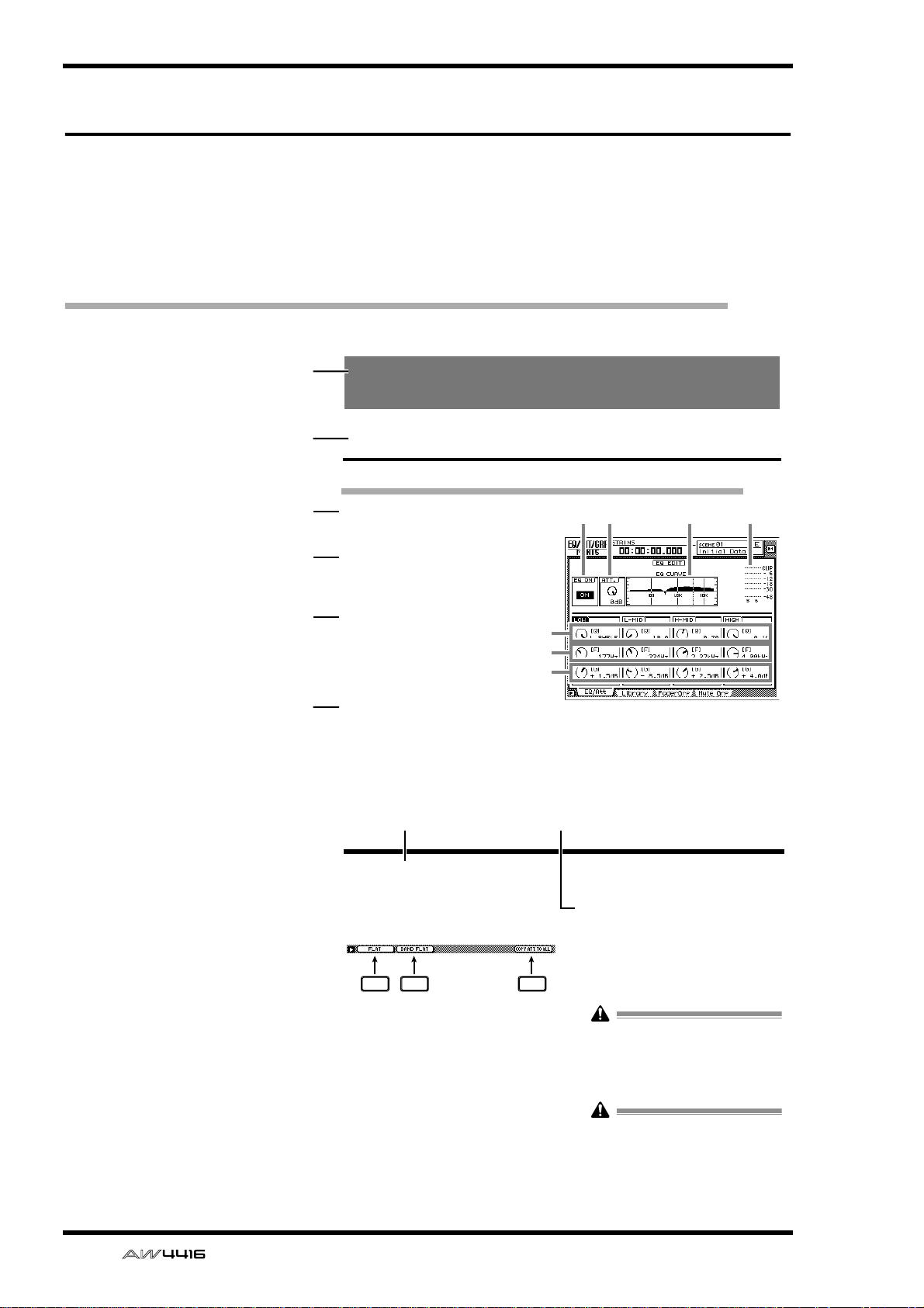
EQ/Att page
EQ and attenuation settings
[Function]
Make four-band EQ and attenuation settings for the selected channel.
[Key operation]
• [EQ] key → [F1] key (EQ/Att) key
• Repeatedly press the [EQ] key until the
screen shown at the right appears.
[Mouse operation]
M button → EQ button → EQ/Att tab
[Screen functions]
A
EQ ON button
This switches EQ on/off. When this page is displayed, you can use the [ENTER] key to switch
this button on/off regardless of the cursor location.
7 8
■ Additional functions in the EQ/
Att page
In the EQ/Att page you can press the [SHIFT] key to
assign the following additional functions to the
[F1]–[F2] and [F5] keys.
F1 F2 F5
• [F1] (FLAT) key
Reset all bands to a boost/cut amount of 0.0 dB
(off if HPF/LPF is selected).
• [F2] (BAND FLAT) key
Reset only the selected band to a boost/cut
amount of 0.0 dB (off if HPF/LPF is selected).
• [F5] (COPY ATT. TO ALL) key
Copy the attenuation setting of the selected
channel to all channels. (However, the stereo
output channel is excepted.)
2134
5
6
7
the EQ type to H.SHELF (shelving), and turning
it all the way in the counter-clockwise direction
will switch the EQ type to LPF (low pass filter).
Range: 10–0.10, HPF/L.SHELF (LOW band
only), LPF/H.SHELF (HIGH band only)
EQ/ATT/GRP screen
● Copying the attenuation setting
to all channels
[Procedure]
1. Access the EQ/Att page for the copy
source channel, and move the cursor to
the ATT. knob.
2. Press the [SHIFT] key + [F5] key.
A CONFIRMATION popup window will appear,
asking you to confirm the copy.
If the cursor is at a location other than the
ATT. knob, a message of “Can’t Copy This
Parameter” will appear, and the copy will not
occur.
3. To execute the copy, move the cursor to
the OK button and press the [ENTER] key.
Only the attenuation setting will be copied. If
you wish to copy EQ settings, you must store
the settings in the library and recall them into
the copy destination channel. For the procedure refer to page 47.
viii — Reference Guide
Page 8
SONG screen
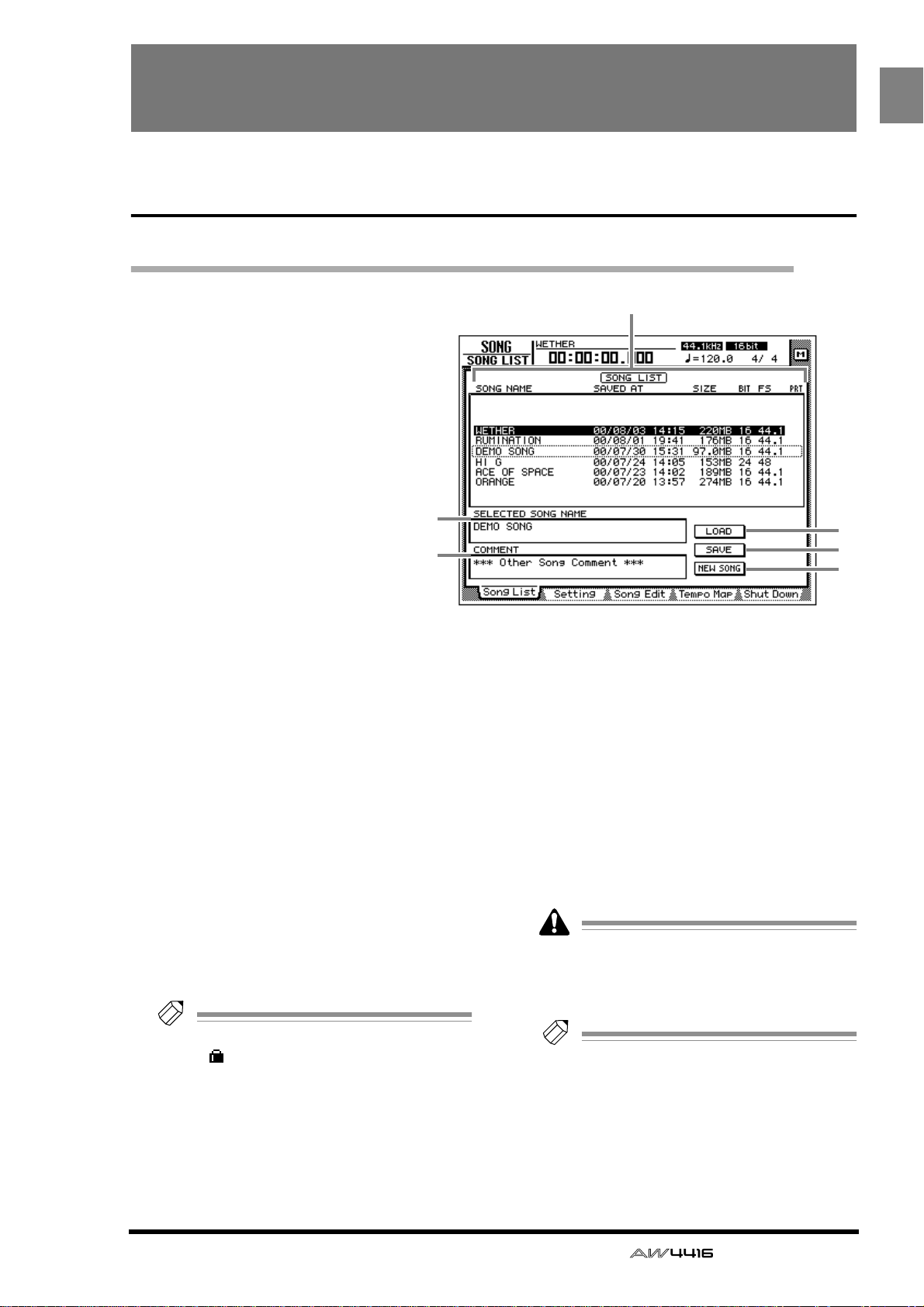
Song List page
Saving/loading a song
SONG
[Function]
Load a song from hard disk, or
save the current song to hard disk.
[Key operation]
• [SONG] key → [F1] (Song List)
key
• Repeatedly press the [SONG]
key until the display shown at
right appears.
[Mouse operation]
M button → SONG button → Song
List tab
[Screen functions]
A Song list
This lists the songs that are saved on the internal
hard disk. The highlighted line is the current
song, and the line enclosed by a dotted line is
the song selected for loading. Use the [DATA/
JOG] dial to select the song for loading.
This list shows the following data for each song.
• SONG NAME..... First 16 characters of the
song name
• SAVED AT...........Date and time at which the
song was last saved
• SIZE ...................Size of the song
• BIT/FS ................Quantization (bit number)/
sampling frequency of the
song
• PRT ....................Song protect on/off (→ P.2)
Tip!
If song protect is on, the PRT column will
show “ ”.
B SELECTED SONG NAME
This shows the name of the song selected by the
cursor. This field is for display only, and cannot
be edited.
2
3
1
4
5
6
C COMMENT
This shows the comment of the song selected by
the cursor. This field is for display only, and cannot be edited.
Comments for other than the current song will
be displayed as “*** Other Song Comment ***”.
D LOAD button
This button loads the song enclosed by the dotted line in the list.
E SAVE button
This button saves the current song.
The location of the dotted frame in the list
does not affect the save location of the current song. It is not possible to change the
save location of the current song.
Tip!
For details on loading or saving songs, refer
to Operation Guide “Chapter 11. Song management.”
F NEW SONG button
This button creates a new song. For details on
creating a new song, refer to Operation Guide
“Chapter 5. Recording on the AW4416.”
— Reference Guide 1
Page 9
SONG screen
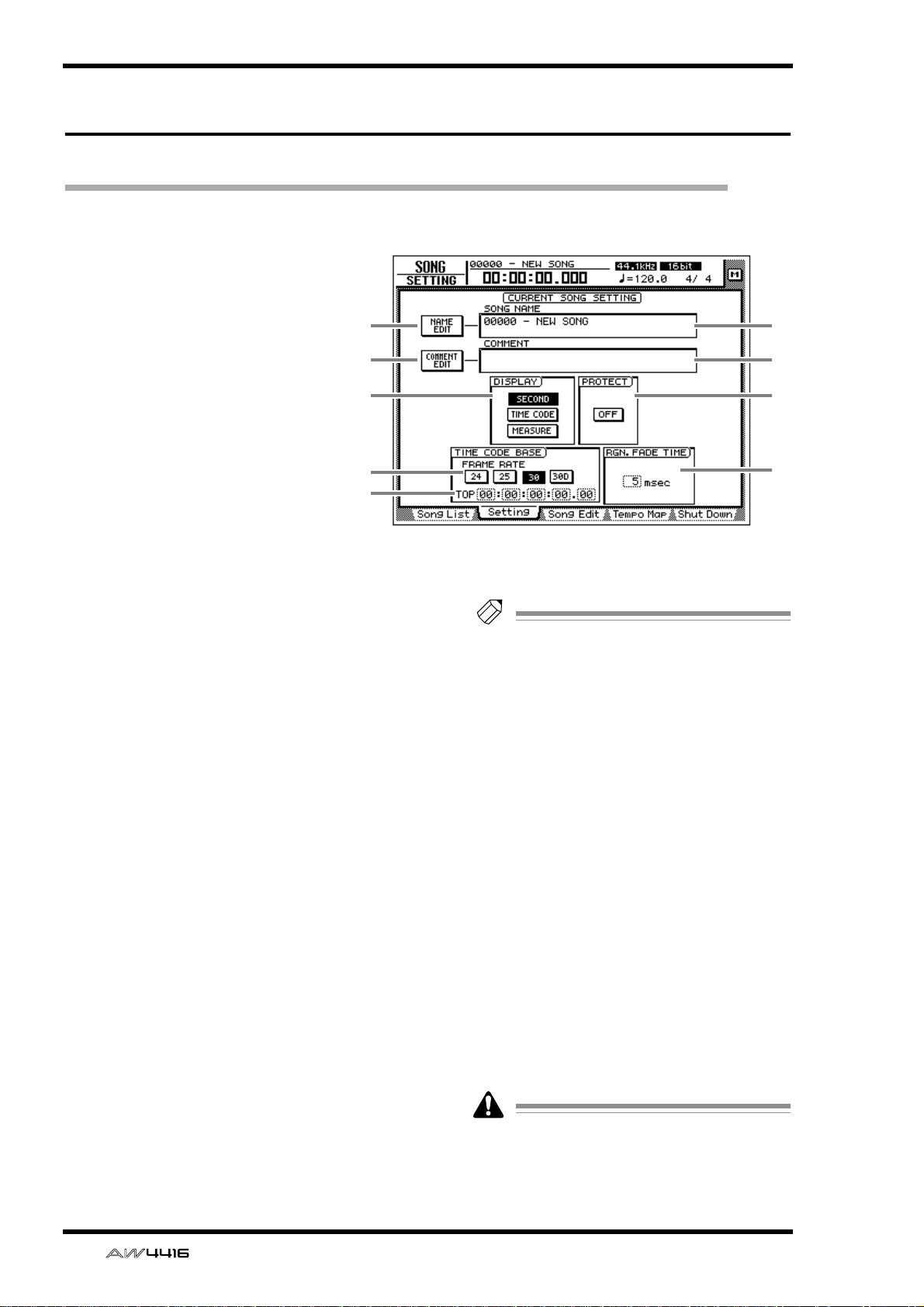
Setting page
Make various settings for the current song
[Function]
Make various settings for the current song, such as editing the song
name, selecting the counter display method, and selecting the
time code frame rate.
12
[Key operation]
• [SONG] key → [F2] (Setting) key
• Repeatedly press the [SONG]
key until the display shown at
the right appears.
[Mouse operation]
M button → SONG button → Setting tab
[Screen functions]
A NAME EDIT button
This button edits the song name of the current
song.
B SONG NAME
This displays the song name of the current song.
C COMMENT EDIT button
This button edits the comment of the current
song.
D COMMENT
This displays the comment of the current song.
E DISPLAY
You can select one of the following three display methods for the current location that is
shown in the counter/level meter and in the
counter in the upper part of the display.
● SECOND button
The counter will be displayed as time (hours/
minutes/seconds/milliseconds).
● TIME CODE button
The counter will be displayed as time code
(hours/minutes/seconds/frames/sub-frames).
● MEASURE button
The counter will be displayed as measures
(measures/beats/ticks).
3
5
7
8
4
6
9
Tip!
The display method you select here will also
affect how the track editing range is specified
(EDIT screen TR Edit page), and how locate
points are displayed (TRACK screen Mark
Adj. page etc.).
F PROTECT
This specifies the protect setting of the song.
When you move the cursor to the button in the
PROTECT area and press the [ENTER] key, the
button will alternate between ON and OFF.
When protect is on, it will not be possible to
edit or record tracks, edit the sampling pads, or
set/change locate points.
G FRAME RATE buttons
Use the following four buttons to select the
frame rate of the time code. The frame rate setting will affect the counter time code display
and the MTC that is transmitted and received.
• 24 button ...........24 fps
• 25 button ...........25 fps
• 30 button ...........30 fps (30 non-drop frame)
• 30D button ........29.97 fps (30 drop-frame)
If you wish to use MTC to synchronize the
AW4416 and an external device, you must
use the FRAME RATE buttons to match the
frame rate of the two devices.
2 — Reference Guide
Page 10
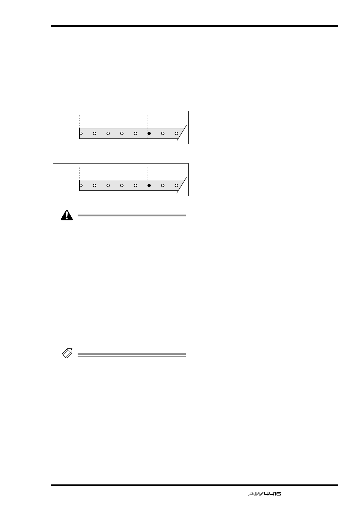
H TOP
This adjusts the time code time that corresponds
to the beginning of the song (“time code top”) in
the range of “00:00:00:00.00”–
”24:00:00:00.00”. (Negative values cannot be
set.) Move the cursor to the TOP area, and use
the [DATA/JOG] dial to adjust the hours/minutes/seconds/frames/subframes value.
Time code top= 00:00:00:00.00
Time code
display
Time code top= 00:00:05:00.00
Time code
display
00:00:00:00.00 00:00:05:00.00
Song
00:00:055:00.00 00:00:10:00.00
Song
SONG screen
• Changing the time code Top will affect the
time code indications in the display and the
MTC that the AW4416 transmits and
receives.
• When you modify the time code Top, the
start point and end point will be adjusted
automatically. For details on the start point
and end point, refer to the explanation in
“TRACK screen/Mark Adj. page.”
I RGN. FADE TIME (region fade time)
This parameter automatically fades-in/fades-out
the starting and ending point of regions. You can
select from 3, 5, 10, 20, or 45 msec as the time
over which the fade-in/out will take place
(“region fade time”). The default setting is 5
msec.
Tip!
If the level changes abruptly at the start/end
point of a region, noise or a click may be
heard during playback. For this reason, it is
not possible to set the region fade time to 0
msec. If you notice noise or clicks, set the
region fade time to a longer value.
— Reference Guide 3
Page 11
SONG screen
Song Edit page
Deleting/copying/optimizing songs
[Function]
Edit songs saved on the internal hard disk,
such as by deleting, copying, or optimizing them.
1
[Key operation]
• [SONG] key → [F3] (Song Edit) key
• Repeatedly press the [SONG] key until
the screen shown at the right appears.
2
[Mouse operation]
M button → SONG button → Song Edit
tab
3
6
5
4
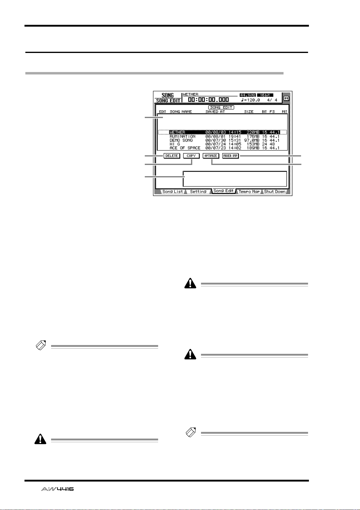
[Screen functions]
A Song list
This lists the songs saved on the internal hard
disk. The current song is highlighted in the list.
An “E” symbol displayed at the left edge of the
list indicates a song selected for editing. The following information is also displayed in the song
list.
• SONG NAME .....First 16 characters of the
song name
• SAVED AT...........Date and time at which the
song was last saved
• SIZE....................Size of the song
• BIT/FS.................Quantization (bit number)/
sampling frequency of the
song
• PRT.....................Song protect on/off status
Tip!
• When you use the cursor to select a song in
the list and press the [ENTER] key, the “E”
symbol that indicates the editing selection
will alternately appear and disappear.
• Depending on the operation, you may be
able to select more than one song for editing.
B DELETE button
This button deletes the song marked by the “E”
symbol from the internal hard disk.
• The current song cannot be deleted.
• A deleted song is gone forever. Use this
operation with caution.
C COPY button
This button copies the song marked by the “E”
symbol onto the internal hard disk.
D OPTIMIZE button
This button optimizes the song marked by the
“E” symbol. When optimize is executed, audio
files not currently used by that song (e.g., undo
files) will be deleted.
Optimize can be executed on only one song
at a time. Optimize can be executed on the
current song.
E MIXER IMP (mixer import) button
This button imports the mixer settings (scene memory/automix/tempo map/libraries) from the song
marked by the “E” symbol into the current song.
Only one song can be selected as the import
source for mixer data. The current song cannot be selected as the import source.
F Parameter area
When you move the cursor to one of the buttons 2–5, the operation (DELETE/COPY/OPTIMIZE/MIXER IMPORT) that can be executed by
that button will appear in this area.
Tip!
For details on using each operation, refer to
Operation Guide “Chapter 11. Song Management.”
4 — Reference Guide
Page 12
Tempo Map page
Programming the tempo map
[Function]
Program tempo data and time signature data into the tempo map.
[Key operation]
• [SONG] key → [F4] (Tempo
Map) key
• Repeatedly press the [SONG]
key until the screen shown at the
right appears.
[Mouse operation]
M button → SONG button →
Tempo Map tab
1
SONG screen
2
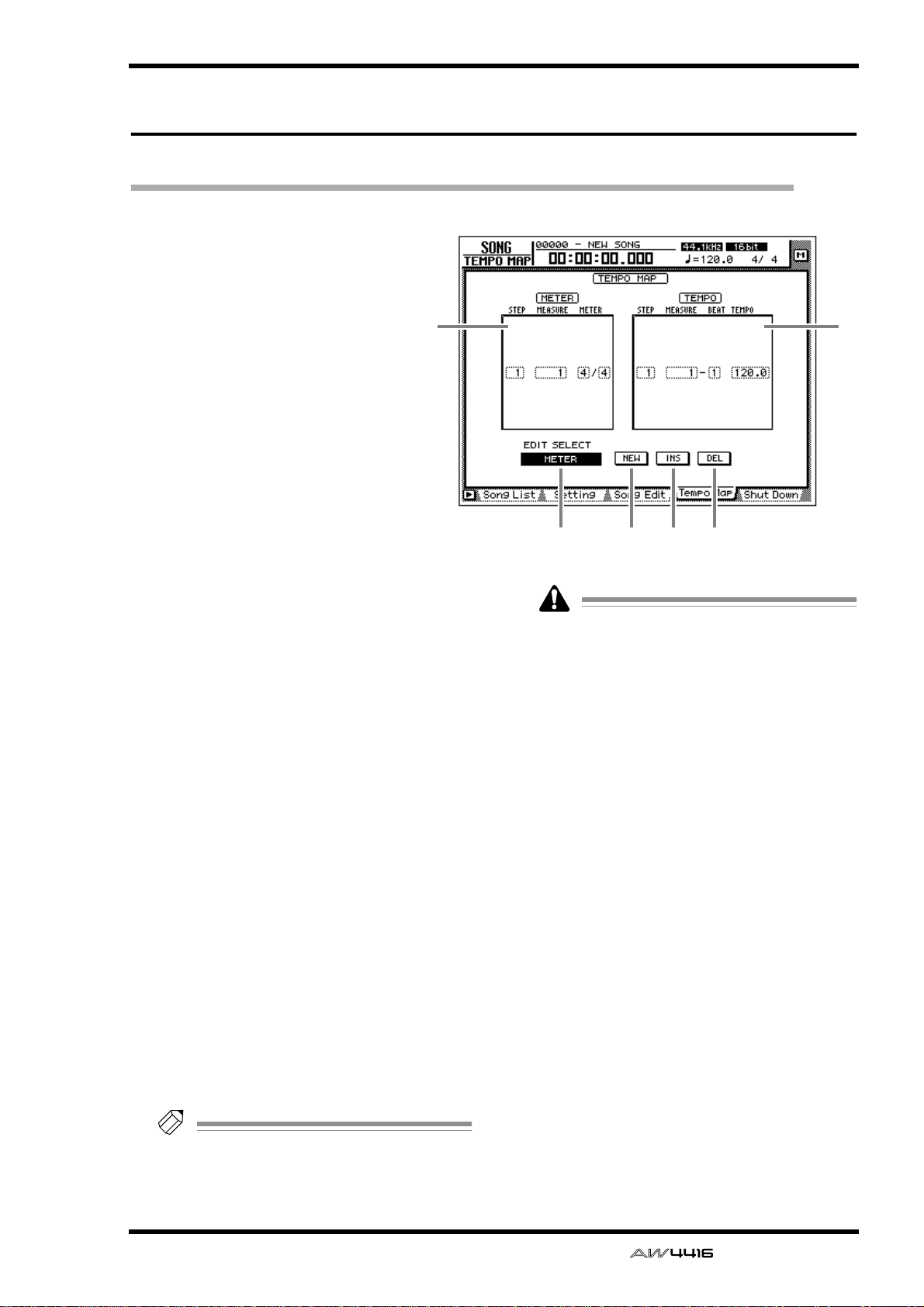
[Screen functions]
A METER
In this area you can specify the time signature.
The area enclosed by the dotted frame is the
currently selected time signature data. In the
METER area you can make the following settings for the STEP/MEASURE/METER items.
● STEP
Move the cursor to this area and rotate the
[DATA/JOG] dial to select the number (step
number) of the time signature data. The step
number is assigned consecutively, starting at the
time signature data of the lowest-numbered
measure.
● MEASURE
Move the cursor to this area and rotate the
[DATA/JOG] dial to modify the measure number
of the time signature. If you move the time signature beyond the previous or next time signature data, their step numbers will be exchanged
automatically.
● METER
Move the cursor to this area and rotate the
[DATA/JOG] dial to specify the time signature
(2/1–8/8) for that measure. The numerator and
denominator of the time signature can be set
independently.
Tip!
When the AW4416 is in the default state,
time signature data of 4/4 is already input at
measure 1.
3
• It is not possible to move the time signature
data of measure 1.
• It is not possible to place two time signatures
at the same measure. If you move the cursor
to the MEASURE area and specify the same
measure number as an existing time signature, the previous time signature data will be
deleted.
4 5 6
B TEMPO
In this area you can specify tempo data. The
area enclosed by the dotted line is the currently
selected tempo data. In the TEMPO area you
can make the following settings for the STEP/
MEASURE/BEAT/TEMPO items.
● STEP
Move the cursor to this area and rotate the
[DATA/JOG] dial to select the number (step
number) of the tempo data. The step number is
assigned consecutively, starting at the tempo
data of the lowest-numbered measure.
● MEASURE/BEAT
Move the cursor to this area and rotate the
[DATA/JOG] dial to modify the location (measure/beat) of the tempo data. If you move the
tempo data beyond the previous or next tempo
data, their step numbers will be exchanged
automatically.
— Reference Guide 5
Page 13
SONG screen
● TEMPO
Move the cursor to this area and rotate the
[DATA/JOG] dial to set the tempo (BPM) of that
location. The BPM value can be set in a range of
20.0–300.0, in 0.1 steps.
Tip!
When the AW4416 is in the default state,
tempo data of BPM=120 is already input at
measure 1 beat 1.
• The tempo data at step number 1 cannot be
moved.
• It is not possible to place two tempo data at
the same location. If you move the cursor to
the MEASURE/BEAT area and specify the
same location as an existing tempo data, the
previous tempo data will be deleted.
C EDIT SELECT button
Use this button to specify whether you will edit
time signature data (METER) or tempo data
(TEMPO). Move the cursor to the button and
press the [ENTER] key to switch between
METER and TEMPO.
D NEW button
When you move the cursor to this button and
press the [ENTER] key, new time signature/
tempo data will be added following the last step
number that is currently input.
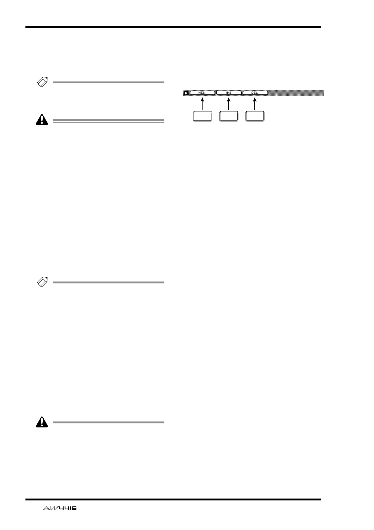
■ Additional functions in the
Tempo Map page
In the Tempo Map page, pressing the [SHIFT] key
will assign the following functions to the [F1]–[F3]
keys.
F1 F2 F3
• [F1] (NEW) key
This key inputs additional time signature data or
tempo data. This is the same function as the 4
NEW button.
• [F2] (INS) key
This key inserts time signature data or tempo
data. This is the same function as the 5 INS
button.
• [F3] (DEL) key
This key deletes time signature data or tempo
data. This is the same function as the 6 DEL
button.
Tip!
• For details on inputting the tempo map, refer
to Operation Guide “Chapter 15. MIDI.”
• A maximum of 26 time signature data/tempo
data items can be input in the METER area/
TEMPO area.
E INS button
When you move the cursor to this button and
press the [ENTER] key, new time signature/
tempo data will be inserted in the step number
before the currently selected time signature/
tempo data.
F DEL button
When you move the cursor to this button and
press the [ENTER] key, the currently selected
time signature/tempo data will be deleted.
It is not possible to delete the time signature/
tempo data of step number 1.
6 — Reference Guide
Page 14
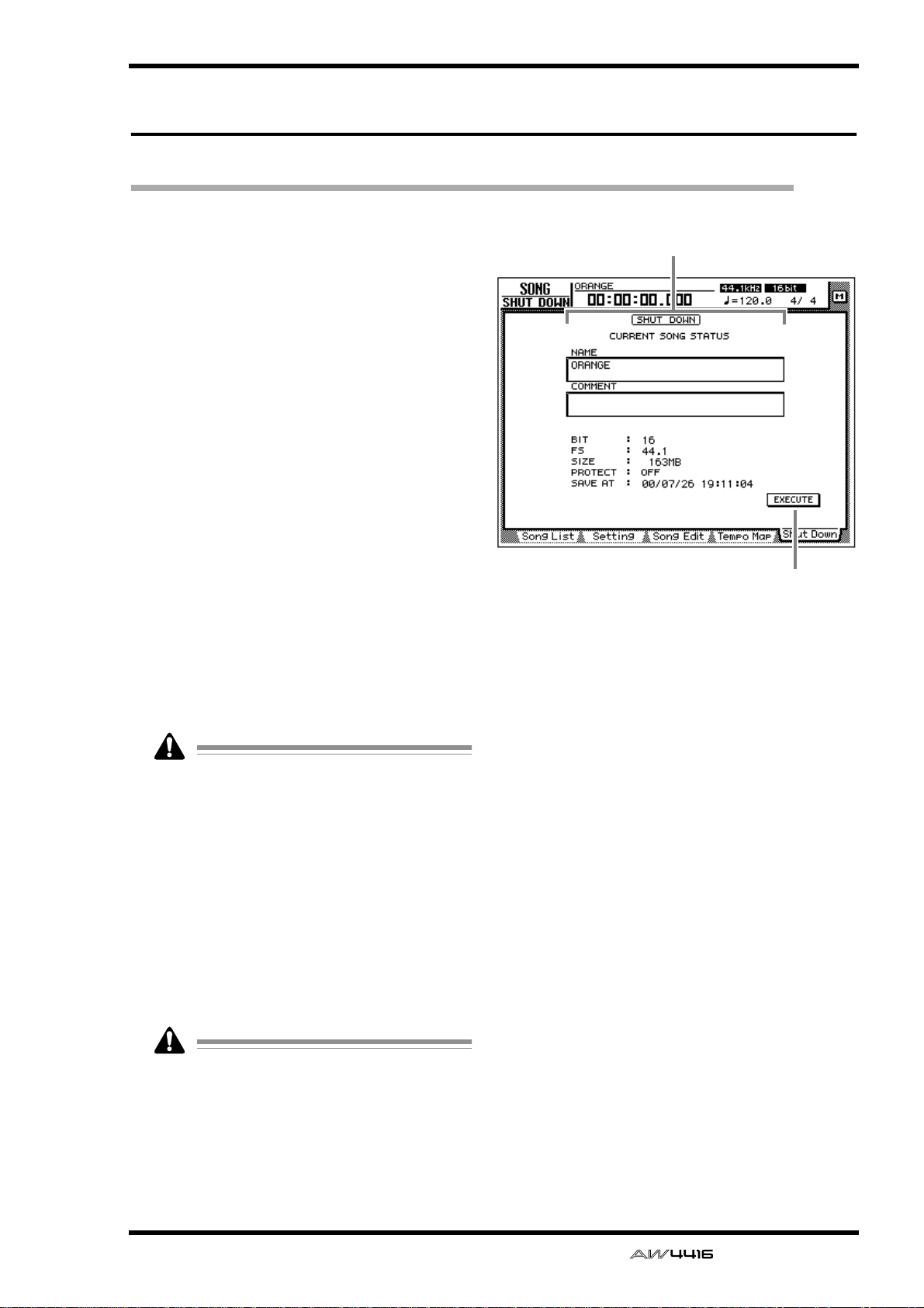
Shut Down page
Shut down the AW4416
[Function]
Shut down the AW4416 so that the power can
be turned off.
[Key operation]
• [SONG] key → [F5] (Shut Down) key
• Repeatedly press the [SONG] key until the
screen shown at the right appears.
[Mouse operation]
M button → SONG button → Shut Down tab
SONG screen
1
[Screen functions]
A Current song status
This area displays various information on the
last-saved song.
The data for the current song (date, size,
quantization bits, protect) shown here in the
song list is the data for when the song was
last saved. When you perform the Save procedure and press the [ENTER] key, it will be
overwritten by the new data.
B EXECUTE button
In this page, the cursor is fixed at the EXECUTE
button, so you can shut-down simply by pressing the [ENTER] key. For details on the order in
which the AW4416 and peripheral devices
should be shut down, refer to Operation Guide
“Important points you must observe.”
2
If you turn off the power of the AW4416
without performing the shut-down operation,
audio data on the internal hard disk may be
damaged. Be sure to perform this shut-down
operation before turning off the power of the
AW4416.
— Reference Guide 7
Page 15
QUICK REC screen
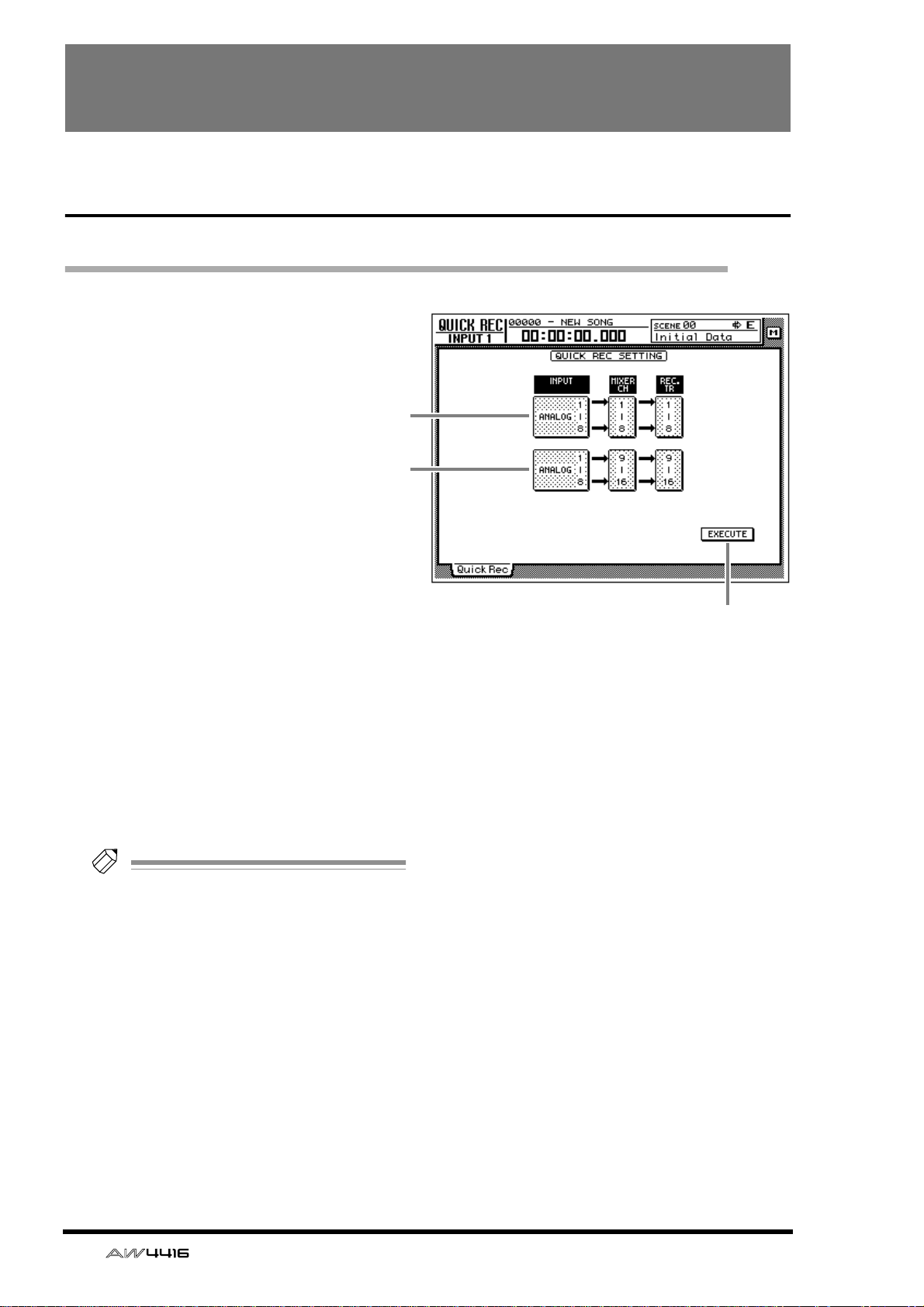
Quick Rec page
Simultaneously recording 16 inputs/16 tracks
[Function]
Instantly make settings (Quick Rec
function) for simultaneously
recording 16 input sources on
audio tracks 1–16.
[Key operation]
[QUICK REC] key
[Mouse operation]
M button → Quick REC button
[Screen functions]
A Input select 1–8
B Input select 9–16
Select from the following input sources to send
to audio tracks 1–8/9–16.
• ANALOG 1–8 .....INPUT jacks 1–8
• SLOT1 1–8..........INPUT 1–8 of an I/O card
(slot 1)
• SLOT2 1–8..........INPUT 1–8 of an I/O card
(slot 2)
1
2
3
Tip!
It is possible to select the same source for 1
and 2. In this case, the same signal will be
sent to tracks 1–8 and tracks 9–16.
C EXECUTE button
When you move the cursor to this button and
press the [ENTER] key, the settings of the
AW4416 will change as follows.
• Mix parameters such as fader, pan, and EQ for
each channel will be reset.
• [REC TRACK SELECT] keys 1–16 will blink,
and tracks 1–16 will be in record-ready mode.
• The output of all tracks 1–16 will be muted.
• Input patch and recorder input patch settings
will be switched as follows.
8 — Reference Guide
Page 16
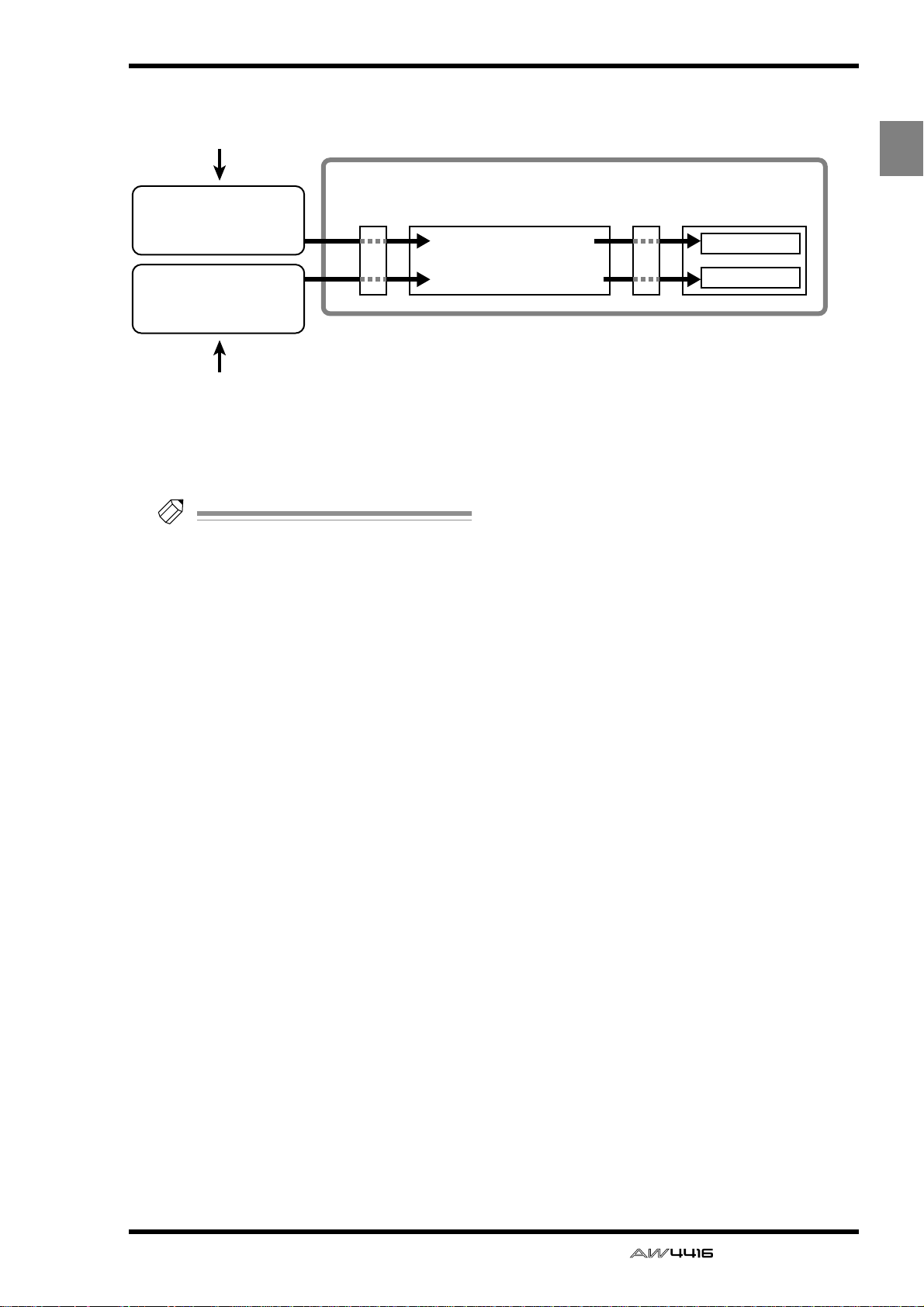
After you have used the EXECUTE button, you
Input channels 1–8
Input channels 9–16
Mixer section
Input
patch
×8
×8
• Input jacks 1–8
• I/O card SLOT1 1–8
• I/O card SLOT2 1–8
Recorder
input
patch
Recorder section
Tracks 1–8
Tracks 9–16
1 Input select 1–8
2 Input select 9–16
• Input jacks 1–8
• I/O card SLOT1 1–8
• I/O card SLOT2 1–8
can simply press the [REC] key + [PLAY] key to
simultaneously record 16 inputs on tracks 1–16.
QUICK REC screen
REC
QUICK
Tip!
• To defeat record-ready and mute settings for
tracks 1–16, press the [ALL SAFE] key.
• For details on operation of the Quick Rec
function, refer to Operation Guide “Chapter
8. Patching.”
— Reference Guide 9
Page 17
MASTERING screen
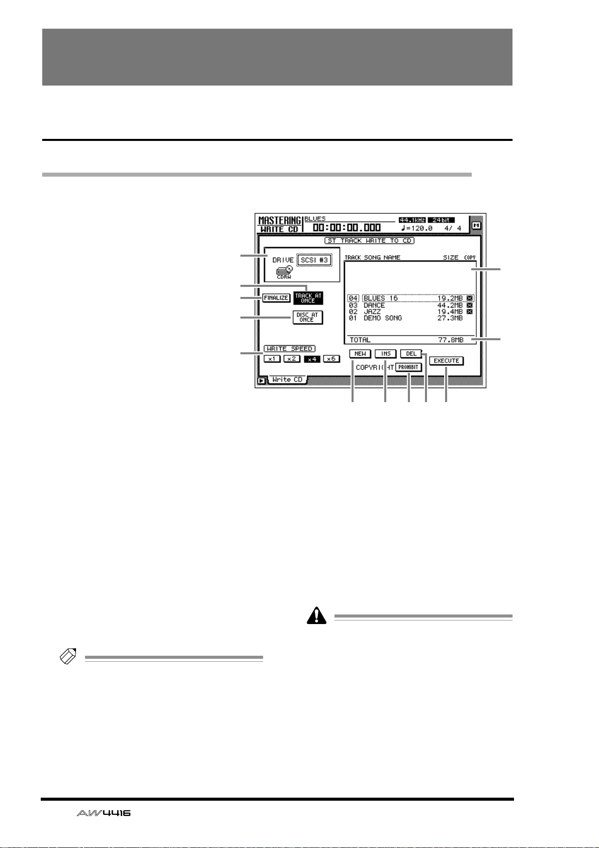
Write CD page
Using a CD-RW drive to create an audio CD
[Function]
Create an audio CD by writing the
stereo track data of songs to CD-R/
RW media as CD audio tracks.
[Key operation]
[MASTERING] key
[Mouse operation]
M button → MAST button
[Screen functions]
A DRIVE
Select the SCSI ID number of the internal or
external CD-RW drive.
B FINALIZE button
When you press this button, CD-R media that
was written using Track At Once will be finalized (information on track locations etc. will be
written into the data area). You must perform the
finalize operation in order for CD-R media written using Track At Once to be playable on a CD
player.
Tip!
If you used Disc At Once to write the data,
finalize will be performed automatically. For
this reason, the FINALIZE button will be displayed only if the TRACK AT ONCE button 3
is turned on.
1
3
2
4
5
9 J
LK8
C TRACK AT ONCE button
D DISC AT ONCE button
Use these buttons to select the way in which
data will be written to the CD-R/RW media
(either Track At Once or Disc At Once). Before
you execute the Write operation, you must
move the cursor to one of these buttons and
press the [ENTER] key.
CD-RW media does not support Track At
Once.
E WRITE SPEED buttons
Use the x1, x2, x4, and x6 buttons to select the
writing speed (normal speed/double speed/
quad speed/x6 speed). Normally you should
select the fastest speed supported by your CDRW drive.
6
7
10 — Reference Guide
Page 18
MASTERING screen
F Track list
Here you can select the stereo tracks that will
be written as audio tracks on the CD.
The track list shows the following information.
● TRACK
This is the track number on the CD. Move the
cursor to this area and rotate the [DATA/JOG]
dial to change the track number.
● SONG NAME/SIZE/COPY
This shows the song name, stereo track data
size, and copy protect setting of songs that contain a stereo track. Move the cursor to this area
and use the [DATA/JOG] dial to select the stereo
track that will be written to the corresponding
audio track.
• The track list will show only the stereo tracks
of songs whose sampling frequency is
44.1 kHz. Stereo tracks of 48 kHz sampling
frequency songs will not be displayed.
• If a 24 bit / 44.1 kHz stereo track is selected,
the lower 8 bits will be discarded when the
data is written, converting it into 16 bit /
44.1 kHz data.
Tip!
If CD-R media containing data written using
Track At Once is in the CD-RW drive, the
SONG NAME/SIZE/COPY area will indicate
“–EXISTING–”.
● PERMIT
Digital copying of the corresponding track will
be permitted.
Tip!
If the button is displayed as PROHIBIT, an
“ ” symbol will be displayed in the COPY
column of the track list.
L EXECUTE button
Use this button to execute writing (mastering) to
CD-R/RW media.
Tip!
• The AW4416 has a “writing test” function
that can check before mastering is performed to see whether data transmission
errors will occur. By default, this test will not
be performed. However, you can make settings so that the test will be performed
before writing, or execute the test by itself.
(→ P.37)
• For details on the procedure of the Mastering
function, refer to Operation Guide “Chapter
17. Mastering.”
■ Additional functions in the Write
CD page
In the Write CD page you can press the [SHIFT] key
to assign the following functions to the [F1]–[F5]
keys.
ING
MASTER-
G Total
This shows the total of the SIZE column of the
track list. A maximum of approximately 650 MB
can be written to 74 minute CD-R/RW media.
H NEW button
Add a new audio track to the track list.
I INS button
Insert a new audio track after the track number
currently selected in the track list.
J DEL
Delete the currently selected audio track from
the track list.
K COPYRIGHT button
Set the copy protect setting of the audio track
currently selected in the track list. Move the
cursor to this button and press the [ENTER] key
to switch between the following two button displays.
● PROHIBIT
Digital copying of the corresponding track will
be prohibited.
F1 F2 F3 F4 F5
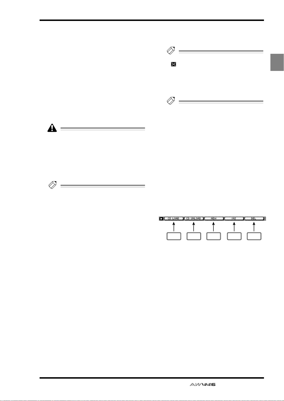
• [F1] (CD LOAD) key
Close the tray of the CD-RW drive.
• [F2] (CD UNLOAD) key
Eject the tray of the CD-RW drive.
• [F3] (NEW) key
Add a new audio track to the track list 6. This is
the same function as the NEW button 8.
• [F4] (INS) key
Insert a new audio track after the track number
currently selected in the track list 6. This is the
same function as the INS button 9.
• [F5] (DEL) key
Delete the audio track currently selected in the
track list 6. This is the same function as the DEL
button J.
— Reference Guide 11
Page 19
CD PLAY screen
CD Play page
Use the CD-RW drive to play an audio CD
[Function]
Use a CD-RW drive connected to
the AW4416 to play back an audio
CD (CD Play function).
[Key operation]
[CD PLAY] key
[Mouse operation]
M button → CD button
1
2
3
4
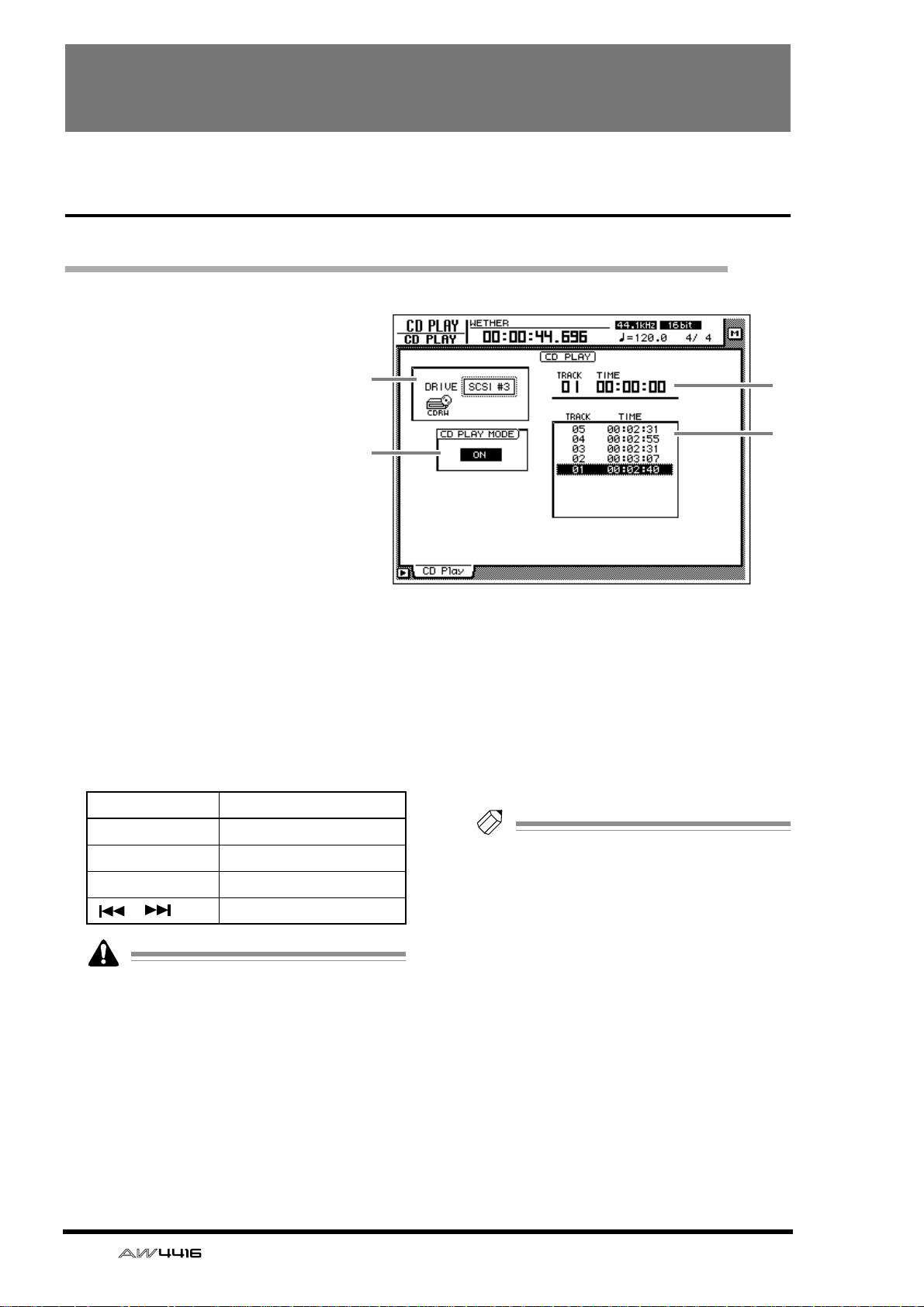
[Screen functions]
A DRIVE
Select the SCSI ID number of the internal or
external CD-RW drive.
B CD PLAY MODE button
This button switches the CD Play function on/
off. When the CD PLAY function is on, you can
use the keys of the Transport section to operate
the CD-RW drive.
Key CD-RW drive operation
[PLAY] key Play the CD
[STOP] key Stop the CD
[FF]/[REW] keys Rewind/fast-forward the CD
[ ]/[ ] keys Select tracks
• While the CD PLAY MODE button 2 is on,
all keys except the [CURSOR] keys, [DATA/
JOG] dial, [ENTER] key, and Transport section keys will be disabled.
• The CD audio signal is routed through the
stereo output channel and output from the
STEREO OUT jacks. (Use the STEREO fader
to adjust the volume.) During this time, the
signals of other channels will not be sent to
the stereo output channel.
• For details on the CD Play function, refer to
Operation Guide “Chapter 17. Mastering.”
C Counter
This displays the track number (TRACK) currently selected in the track list 4, and the
elapsed time of that track (TIME).
D Track list
This list shows the audio track numbers on the
CD (TRACK area), and the times for each track
(TIME area). The currently selected audio track
will be highlighted.
Tip!
You can move the cursor to the track list and
switch the playback track by using the
[DATA/JOG] dial and the [ENTER] key.
12 — Reference Guide
Page 20

■ Additional functions in the CD
Play page
In the CD Play page you can press the [SHIFT] key
to assign the following functions to the [F1]–[F2]
keys.
F1 F2
• [F1] (CD LOAD) key
Close the tray of the CD-RW drive.
• [F2] (CD UNLOAD) key
Eject the tray of the CD-RW drive.
CD PLAY screen
CD
PLAY
— Reference Guide 13
Page 21

SET UP screen
Patch IN page
Patching a signal to a channel/track
[Function]
Assign signals to the inputs of input
channels 1–24, return channels 1/2,
and recorder tracks 1–16.
[Key operation]
• [SETUP] key → [F1] (Patch IN) key
• Repeatedly press the [SETUP] key
until the display shown at right
appears.
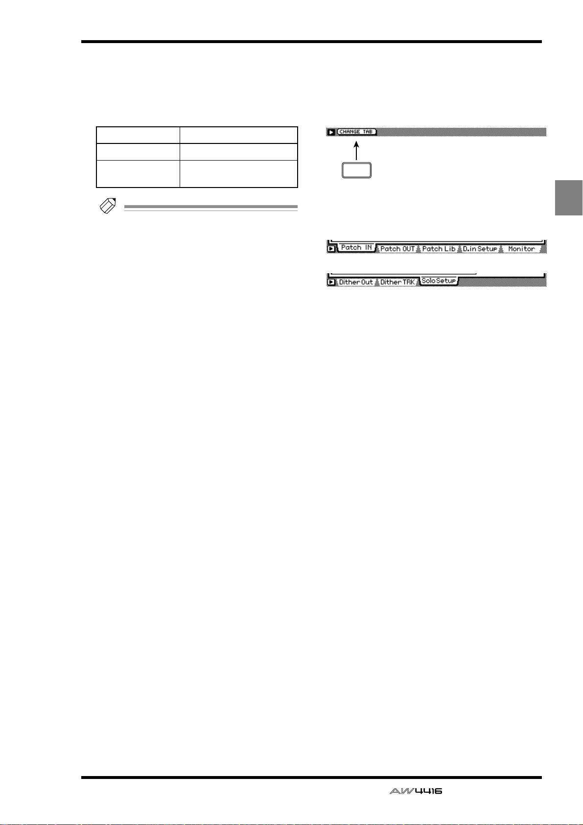
*1. In the SET UP screen, the tabs dis-
played at the bottom are divided
into two groups. If the Patch IN tab is
not assigned to the [F1] key when
you press the [SETUP] key, press the
[SETUP] key + [F1] (CHANGE TAB)
key to switch the tab.
(*1)
[Mouse operation]
M button → SETU button → Patch IN tab
[Screen functions]
A MIXER CHANNEL INPUT ASSIGN
Select the signal that will be assigned to input
channels 1–24 and return channels 1/2. The following signals can be assigned to each channel.
1
2
3
● Return channels 1/2
Display Signal type
EFF1 L/R Return of internal effect 1
● Input channels 1–24
Display Signal type
AD 1–AD 8 INPUT jacks 1–8
SL1-1 – SL1-8
SL2-1 – SL2-8
DIN L/DIN R
SMP 1–SMP 8 Sampling pads 1–8
MET Internal metronome
INPUT 1–8 of an I/O card
(slot 1)
INPUT 1–8 of an I/O card
(slot 2)
L/R channels of the DIGITAL
STEREO IN jack
14 — Reference Guide
EFF2 L/R Return of internal effect 2
AD 1/2–AD 7/8 INPUT jacks 1/2–7/8
SL1-1/2 – SL1-7/8
SL2-1/2 – SL2-7/8
DIN L/R
INPUT 1/2–7/8 of an I/O
card (slot 1)
INPUT 1/2–7/8 of an I/O
card (slot 2)
DIGITAL STEREO IN jack
(stereo)
B EFFECT PATCH
Select whether effects 1/2 will be used via AUX
send/return (AUX7/AUX8), or inserted into a
specified channel (INSERT). For details on operation, refer to Operation Guide “Chapter 10.
Internal effects.”
Page 22
SET UP screen
C RECORDER TRACK INPUT ASSIGN
Here you can select the signals to be assigned
to the inputs of tracks 1–16. The following signals can be assigned.
● Recorder inputs 1–16
Display Signal type
BUS 1–BUS 8 Bus 1–8
DIR 1–DIR16
Tip!
For detai ls on operations in the Patch IN
page, refer to Operation Guide “Chapter 8.
Patching.”
Input channel direct out 1–
16
■ Additional functions in the Patch
IN page
In the Patch IN page you can press the [SHIFT] key
to assign the following function to the [F1] key.
F1
• [F1] (CHANGE TAB) key
Switch between the following two tab displays.
SET
UP
— Reference Guide 15
Page 23
SET UP screen
Patch OUT page
Patch signals to output jacks
[Function]
Assign output signals to the OMNI
OUT jacks, STEREO OUT jacks,
DIGITAL STEREO OUT jack, and
the output channels of I/O cards.
[Key operations]
• [SETUP] key → [F2] (Patch OUT)
(*1)
key
• Repeatedly press the [SETUP]
key until the display shown at
right appears.
*1. In the SET UP screen, the tabs
displayed at the bottom of the
screen are divided into two
groups. If the Patch OUT tab is
not assigned to the [F2] key
when you press the [SETUP]
key, press [SHIFT] key + [F1]
(CHANGE TAB) key to switch
the tabs.
1
2
4
3
[Mouse operation]
M button → SETU button → Patch OUT tab
[Screen functions]
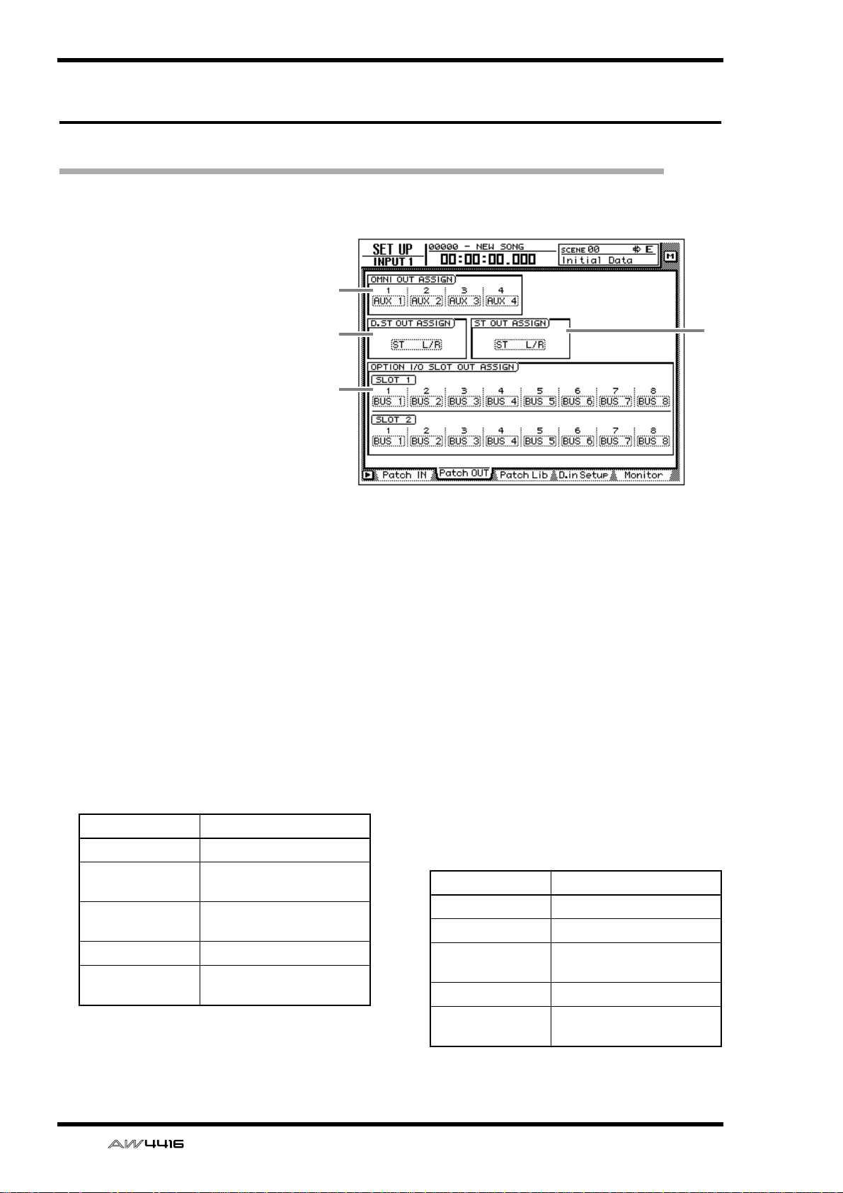
A OMNI OUT ASSIGN
Select the signals that will be output from the
OMNI OUT 1–4 jacks. The following signals
can be assigned.
Display Signal type
AUX 1–AUX 8 AUX buses 1–8
RDR 1–RDR16
ST L/ST R
BUS 1–BUS8 Bus 1–8
DIR 1–DIR16
Recorder direct outputs 1–
16
L/R channels of the stereo
output channel
Input channel direct out 1–
16
B D.ST OUT ASSIGN (digital stereo out
assign)
C ST OUT ASSIGN (stereo out assign)
These respectively select the pair of signals that
will be output from the DIGITAL STEREO OUT
jack and the STEREO OUT jack. The following
signals can be assigned.
Display Signal type
ST L/R Stereo output channel
BUS 1/2–BUS 7/8 Bus 1/2–7/8
DIR 1/2–DIR15/16
AUX 1/2–AUX 7/8 AUX buses 1/2–7/8
Input channel direct out 1/
2–15/16
16 — Reference Guide
RDR 1/2–RDR15/16Recorder direct outs 1/2–
15/16
Page 24
SET UP screen
D OPTION I/O SLOT OUT ASSIGN
This selects the signals that will be output from
I/O cards installed in OPTION I/O slots 1/2. The
following signals can be assigned.
Display Signal type
BUS 1–BUS 8 Buses 1–8
DIR 1–DIR16
AUX 1–AUX 8 AUX buses 1–8
RDR 1–RDR16
ST L/ST R
Tip!
For details on operation in the Patch OUT
page, refer to Operation Guide “Chapter 8.
Patching.”
Input channel direct out 1–
16
Recorder direct outputs 1–
16
L/R channels of the stereo
output channel
■ Additional functions in the Patch
OUT page
In the Patch OUT page you can press the [SHIFT]
key to assign the following function to the [F1] key.
F1
• [F1] (CHANGE TAB) key
Switch between the two tab displays.
— Reference Guide 17
Page 25
SET UP screen
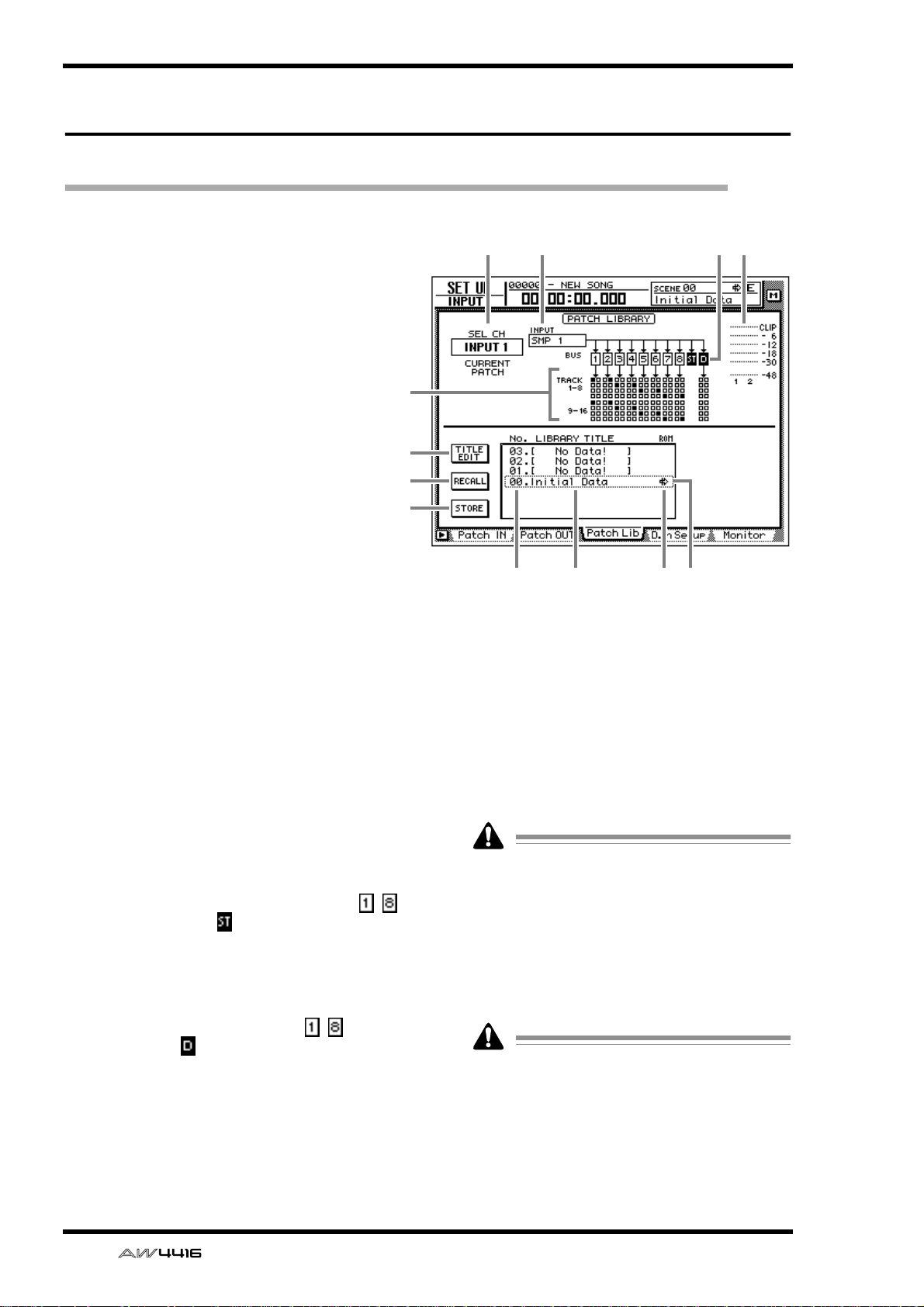
Patch Lib page
Store or recall patching settings
[Function]
Store the settings of the Patch IN/Patch
OUT pages in the patch library, or recall
previously-stored settings.
[Key operation]
• [SETUP] key → [F3] (Patch Lib) key
• Repeatedly press the [SETUP] key until
the display shown at right appears.
*1. In the SET UP screen, the tabs dis-
played at the bottom of the screen are
divided into two groups. If the Patch
Lib tab is not assigned to the [F3] key
when you press the [SETUP] key, press
[SHIFT] key + [F1] (CHANGE TAB) key
to switch the tabs.
(*1)
4
6
7
8
1 2 3 5
[Mouse operation]
M button → SETU button → Patch Lib tab
[Screen functions]
A SEL CH
This indicates the channel currently selected by
the [SEL] key.
B INPUT
This indicates the input signal patched to the
channel shown in 1. Refer to the explanation
of the Patch IN page for the meaning of each
abbreviation.
C BUS
This area shows the buses to which the signal of
the channel is being sent. For buses 1–8 ( – )
and the stereo bus ( ), buses to which that
channel is assigned will be displayed as white
characters on black background.
D TRACK 1-8/9-16
This area displays ■ symbols to indicate the
track inputs to which buses 1–8 ( – ) and the
direct output ( ) of the input channel currently
selected by the [SEL] key are patched.
E Input meter
This shows the input level of the odd-numbered
→ even-numbered channels adjacent to the
channel selected in 1, or the output level of the
stereo output channel.
9
J KL
F TITLE EDIT button
Use this button when you wish to edit the name
(library title) of the patching settings saved in the
library. Move the cursor to the TITLE EDIT button and press the [ENTER] key to access the
TITLE EDIT screen where you can input the
name.
Library number 0 is a recall-only preset, and
therefore its name cannot be changed. Patch
library numbers in which no data has been
stored will be displayed as “No Data!,” and
their title cannot be edited.
G RECALL button
This button recalls the currently selected patching settings from the list.
If you select a number in which nothing has
been stored and attempt to recall it, an error
message of “ERROR NO DATA TO RECALL”
will be displayed, and the recall will not take
place.
H STORE button
Store the current patching settings.
18 — Reference Guide
Page 26
• Library number 0 is a recall-only preset; data
cannot be stored in it. Data can be stored
only in library numbers 1–20.
• When you execute the Store operation, the
patching settings that had been stored in that
number will be erased.
I LIBRARY No. (library number)
This area displays library numbers 00–20.
J LIBRARY TITLE
This area displays the names assigned to the
library settings.
K ROM
Recall-only library number 0 is indicated by a
write-prohibit symbol in this column.
L Selected patching
The patching settings enclosed by the dotted
line in the library list will be the subject of the
Store or Recall operation. In this page, you can
use the [DATA/JOG] dial to select patching settings regardless of where the cursor is located.
SET UP screen
● To store the patching settings
into a library
[Procedure]
1. Access the SET UP screen Patch Lib page.
2. Use the [DATA/JOG] dial to select the
library number 1–20 into which you wish
to store the settings.
3. Move the cursor to the STORE button and
press the [ENTER] key.
The NAME EDIT display will appear, allowing
you to input the name.
Tip!
If STORE CONFIRMATION is turned “OFF”
in the UTILITY screen Prefer.1 page ([UTILITY] key → [F2] key), this popup window will
not appear.
4. Input the library title. For details on inputting characters, refer to Operation Guide
P.60.
■ Additional functions in the Patch
Lib page
In the Patch Lib page you can press the [SHIFT] key
to assign the following functions to the [F1]–[F4]
keys.
F1 F2 F3 F4
• [F1] (CHANGE TAB) key
Switch between the two tab displays.
• [F2] (TITLE EDIT) key
Use this to edit the name (library title) of patching settings saved in the library. This is the same
function as the 6 TITLE EDIT button.
• [F3] (RECALL) key
Recall the currently selected patching settings
from the list. This is the same function as the 7
RECALL button.
• [F4] (STORE) key
Store the current patching settings. This is the
same function as the 8 STORE button.
5. Move the cursor to the OK button and
press the [ENTER] key.
The Store operation will be executed.
● To recall patching settings from a
library
[Procedure]
1. Access the SET UP screen Patch Lib page.
2. Use the [DATA/JOG] dial to select the
library number that you wish to recall.
3. Move the cursor to the RECALL button
and press the [ENTER] key.
A confirmation message will appear.
Tip!
If RECALL CONFIRMATION is turned “OFF”
in the UTILITY screen Prefer.1 page ([UTILITY] key → [F2] key), this popup window will
not appear.
4. Move the cursor to the OK button and
press the [ENTER] key.
The Recall operation will be executed.
— Reference Guide 19
Page 27
SET UP screen
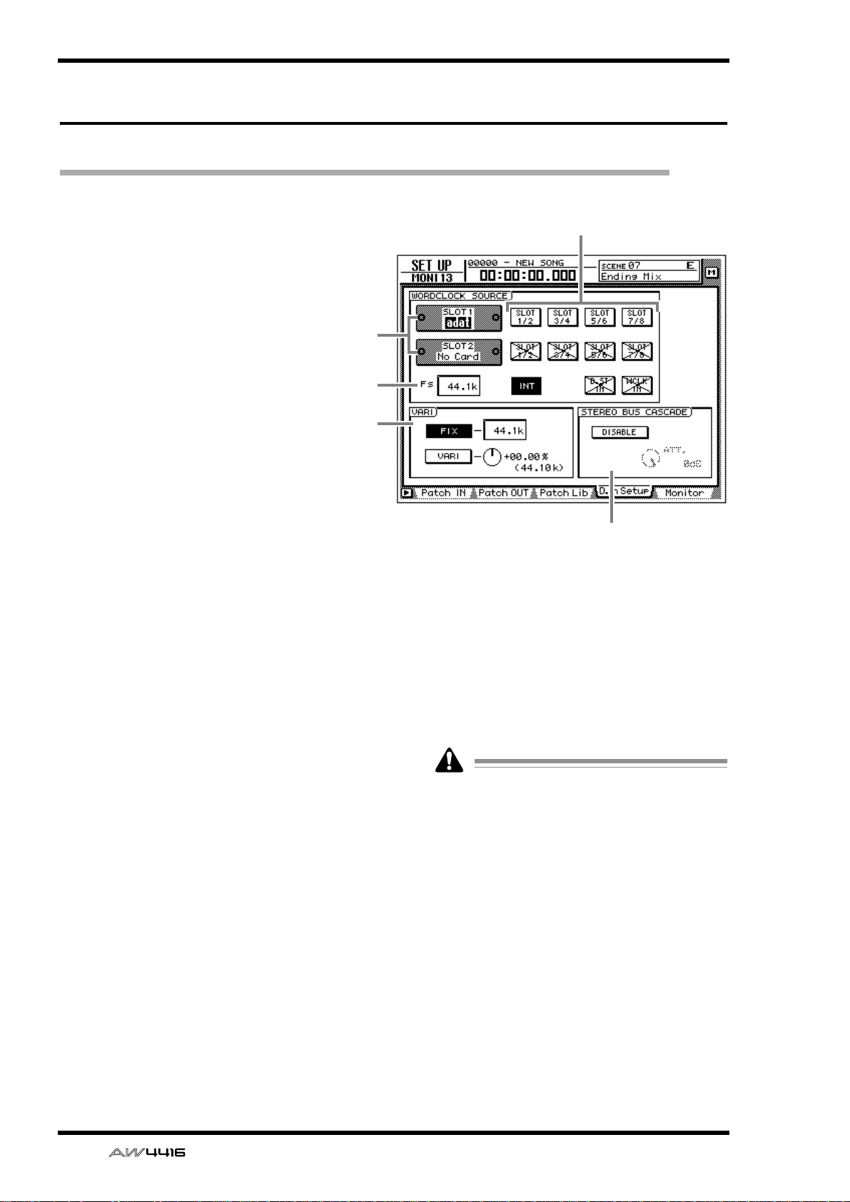
D.in Setup page
Make word clock/cascade settings
[Function]
Select the word clock source to which the
AW4416 will synchronize. In this page
you can also make settings for stereo bus
cascade connections.
[Key operation]
• [SETUP] key → [F4] (D.in Setup) key
• Repeatedly press the [SETUP] key until
the screen shown at the right appears.
*1. In the SET UP screen, the tabs dis-
played at the bottom of the screen are
divided into two groups. If the D.in
Setup tab is not assigned to the [F4]
key when you press the [SETUP] key,
press the [SHIFT] key + [F1] (CHANGE
TAB) key to switch the tabs.
(*1)
1
3
4
2
[Mouse operation]
M button → SETU button → D.in Setup
tab
[Screen functions]
A Slots 1/2
If an optional I/O card is installed in OPTION I/
O slots 1/2, a graphic will be displayed to show
the type of I/O card. Cards in which no card is
installed will be displayed as “No Card!”
B WORD CLOCK SOURCE
From the following choices, select one of the
following clock source to which the AW4416
will synchronize.
● SLOT 1 1/2–7/8
● SLOT 2 1/2–7/8
The input signal from a digital I/O card installed
in OPTION I/O slots 1/2 will be the clock
source. One pair of digital I/O card input channels 1/2–7/8 can be selected.
● INT
The internal clock of the AW4416 will be used
as the clock source.
● D.ST IN
The word clock data included in the input signal of the DIGITAL STEREO IN jack will be the
clock source.
5
● WCLK IN
The word clock data included in the input signal of the WORD CLOCK IN jack will be the
clock source.
• The highlighted button indicates the currently selected word clock source.
• Buttons marked with an “X” indicate that no
digital audio signal is being input from the
corresponding slot/jack.
• Buttons marked by a / indicate that a digital
audio signal is being input from the corresponding slot/jack, but is not synchronized
with the internal clock of the AW4416.
• Buttons without an X or / symbol indicate
that a digital audio signal is being input from
the corresponding slot/jack, and is synchronized with the internal clock of the
AW4416.
20 — Reference Guide
Page 28
SET UP screen
C FS (sampling frequency)
This shows the sampling frequency of the signal
that is currently selected as the clock source.
If you select an external clock as the clock
source, you must check that the sampling frequency of the song matches the frequency of
the external clock. For example if you are
synchronized to a 48 kHz external clock and
record on a 44.1 kHz song, be aware that the
pitch will change when you return the clock
source setting to “INT” and play back.
D VARI (vari-pitch)
If “INT” is selected as the clock source, you can
select whether the sampling frequency will be
fixed (FIX button on) or variable (VARI button
on). If “FIX” is selected, the control change frequency of the internal clock will be displayed at
the right.
If “VARI” is selected, you can move the cursor
to the knob at the right and rotate the [DATA/
JOG] dial to make fine adjustments to the sampling frequency over a range of –5.97%–
+6.00%.
■ Additional functions in the D.in
Setup page
In the D.in Setup page, you can press the [SHIFT]
key to assign the following function to the [F1] key.
F1
• [F1] (CHANGE TAB) key
Switch between the two types of tab display.
E STEREO BUS CASCADE
This selects whether the digital device connected to the DIGITAL STEREO IN jack will be
cascaded with the stereo bus of the AW4416.
When you move the cursor to the “DISABLE”
button and press the [ENTER] key, the button
display will change to “ENABLE,” and the input
signal from the DIGITAL STEREO IN jack will
be sent directly to the stereo bus of the
AW4416. At this time, you can use the ATT.
knob to adjust the level (attenuation) of the
input signal.
In order for the device connected to the DIGITAL STEREO IN jack to be cascade-connected to the stereo bus, the clock source
must be set to “D.ST IN.” If another clock
source is selected, a message of “CANNOT
ASSIGN DIGITAL-ST-IN.” will be displayed,
and it will not be possible to set the button to
“ENABLE.”
— Reference Guide 21
Page 29
SET UP screen
Monitor page
Monitor the digital input signals
[Function]
Monitor the state of the digital audio signals being input from the DIGITAL STEREO IN jack or from digital I/O cards
installed in the OPTION I/O slots.
[Key operation]
• [SETUP] key → [F5] (Monitor) key
• Repeatedly press the [SETUP] key until
the screen shown at the right appears.
*1. In the SET UP screen, the tabs dis-
played at the bottom of the screen are
divided into two groups. If the Monitor
tab is not assigned to the [F5] key
when you press the [SETUP] key, press
the [SHIFT] key + [F1] (CHANGE TAB)
key to switch the tabs.
(*1)
2
1
[Mouse operation]
M button → SETU button → Monitor tab
[Screen functions]
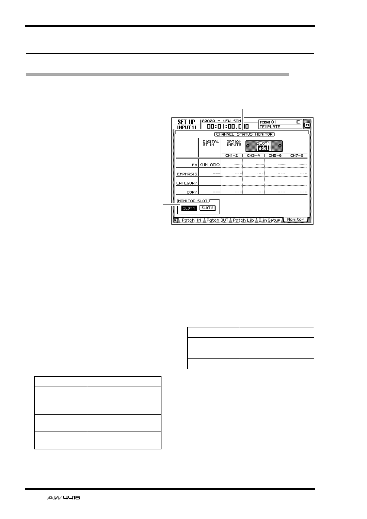
A CHANNEL STATUS MONITOR
This area monitors the state of the digital input
signals from the DIGITAL STEREO IN jack (DIGITAL ST IN) or from a digital I/O card installed
in an OPTION I/O slot (OPTION INPUTS). The
following items are displayed.
● Fs
This shows the sampling frequency of the input
signal.
Display Meaning
44.1k
44.1 kHz sampling frequency
● EMPHASIS
This shows whether the input signal has been
processed by emphasis.
Display Meaning
ON Emphasis on
OFF Emphasis off
??? Unknown
48k 48 kHz sampling frequency
None
UNLOCK
Unknown sampling frequency
No signal being input, or
invalid signal being input
22 — Reference Guide
Page 30

SET UP screen
● CATEGORY
This shows the category of the digital input signal.
Display Meaning
GEN General use
LASER OPTICAL
D/D Conv
D.Broadcast Digital broadcast
Instrument
AD Conv
A/D Conv with (c)
Solid Memory Solid-state memory device
Experimental Experimental device
Unknown Unknown device
Optical laser device such as
a CD player
D/D converter or signal processor
Instrument or sound module
A/D converter (without
copyright data)
A/D converter (with copyright data)
■ Additional functions in the Moni-
tor page
In the Monitor page, you can press the [SHIFT] key
to assign the following function to the [F1] key.
F1
• [F1] (CHANGE TAB) key
Switch between the two types of tab display.
● COPY
This shows the copy permit/prohibit status of
the digital input signal.
Display Meaning
OK Copying permitted
Prohibit Copying prohibited
Tip!
Digital input signals from the OPTION I/O
slots are displayed in units of two adjacent
odd-numbered → even-numbered channels
(channels 1/2, 3/4 ...). The buttons in the
MONITOR SLOT area (2) select whether slot
1 or 2 will be displayed.
B MONITOR SLOT
These buttons select the OPTION I/O slot that
will be monitored in the OPTION INPUTS area.
— Reference Guide 23
Page 31

SET UP screen
Dither Out page
Specify dithering and word length of the digital outputs
[Function]
Turn dithering on/off and specify the word
length of the output signal for the various
digital outputs.
[Key operation]
• [SETUP] key → [F1] (Dither Out) key
• Repeatedly press the [SETUP] key until the
screen shown at the right appears.
*1. In the SET UP screen, the tabs displayed at
the bottom of the screen are divided into
two groups. If the Dither Out tab is not
assigned to the [F1] key when you press
the [SETUP] key, press the [SHIFT] key +
[F1] (CHANGE TAB) key to switch the
tabs.
(*1)
21
[Mouse operation]
M button → SETU button → Dither Out tab
[Screen functions]
A ON/OFF (dithering on/off)
Turn dithering on/off for the DIGITAL STEREO
OUT jack (DIGITAL OUT) or the output channels of the OPTION I/O slots (OPTION OUT
SLOT).
Tip!
• Dithering is a process by which a small
amount of noise is added to the signal in
order to make the sound smoother, preventing the obtrusive sound that can occur if bits
are discarded when digital audio data is
transmitted from a high-resolution system to
a lower resolution system (for example when
copying from a 24 bit system to a 16 bit system).
• For digital I/O cards, dithering is switched
on/off by pairs of adjacent odd-numbered →
even-numbered channels (channels 1/2, 3/4,
...).
■ Additional functions in the Dither
Out page
In the Dither Out page, you can press the [SHIFT]
key to assign the following function to the [F1] key.
F1
• [F1] (CHANGE TAB) key
Switch between the two types of tab display.
B WORD LENGTH (BIT)
Select the word length (number of bits) for the
signals that are output to the DIGITAL STEREO
OUT jack (DIGITAL OUT) or to digital I/O cards
installed in the OPTION I/O slots (OPTION
OUT SLOT). Set this to the word length of the
destination device.
24 — Reference Guide
Page 32

Dither TRK page
Specify dithering and word length for tracks
[Function]
Turn dithering on/off and specify the word
length for recording on tracks 1–16 of the
recorder.
[Key operation]
• [SETUP] key → [F2] (Dither TRK) key
• Repeatedly press the [SETUP] key until
the screen shown at the right appears.
*1. In the SET UP screen, the tabs dis-
played at the bottom of the screen are
divided into two groups. If the Dither
TRK tab is not assigned to the [F1] key
when you press the [SETUP] key, press
the [SHIFT] key + [F1] (CHANGE TAB)
key to switch the tabs.
(*1)
1
SET UP screen
32
[Mouse operation]
M button → SETUP button → Dither TRK
tab
[Screen functions]
A REC TRACK
In pairs of adjacent odd-numbered → evennumbered tracks (tracks 1/2, 3/4 ...), this indicates the tracks for which you can specify dithering and word length. The settings for the
stereo track are common to tracks 1/2.
B ON/OFF (dithering on/off)
Turn dithering on/off for the data that is
recorded on adjacent odd-numbered → evennumbered tracks.
C WORD LENGTH (BIT)
Select the word length (number of bits) for the
data that is recorded on adjacent odd-numbered → even-numbered tracks. Set this to
match the quantization (number of bits) that
you selected when creating the song.
■ Additional functions in the Dither
TRK page
In the Dither TRK page, you can press the [SHIFT]
key to assign the following function to the [F1] key.
F1
• [F1] (CHANGE TAB) key
Switch between the two types of tab display.
— Reference Guide 25
Page 33

SET UP screen
Solo Setup page
Make solo settings
[Function]
Make various settings related to the Solo
function.
[Key operation]
• [SETUP] key → [F3] (Solo Setup) key
• Repeatedly press the [SETUP] key until
the screen shown at the right appears.
*1. In the SET UP screen, the tabs dis-
played at the bottom of the screen are
divided into two groups. If the Solo
Setup tab is not assigned to the [F3]
key when you press the [SETUP] key,
press the [SHIFT] key + [F1] (CHANGE
TAB) key to switch the tabs.
(*1)
1 2 3 4
5
[Mouse operation]
M button → SETU button → Solo Setup
tab
[Screen functions]
A STATUS
Turn on one of the following two buttons to
select the operating mode of the Solo function.
● RECORDING SOLO
If this button is on, the solo signal will be output
via the dedicated SOLO bus to the MONITOR
OUT jacks/PHONES jack. (The output of the
stereo bus and buses 1–8 will not be affected.)
You can also monitor channels that are not
assigned to the stereo bus or to buses 1–8, or
channels whose [ON] key is off.
B LISTEN
When RECORDING SOLO is selected for 1,
you can select one of the following two locations from which the signal will be sent from
each channel to the SOLO bus.
● PRE FADER
The pre-fader signal will be sent to the SOLO
bus. Since the pan setting of the channel will
have no effect, the signal being monitored from
the MONITOR OUT jacks/PHONES jack will be
monaural.
● MIXDOWN SOLO
If this button is on, the solo signal will be output
via the stereo bus to the MONITOR OUT jacks/
PHONES jack. When the Solo function is turned
on, only the channel(s) being soloed will be
sent to the stereo bus, and the remaining channels will be muted. It is not possible to monitor
channels that are not assigned to the stereo bus.
26 — Reference Guide
● AFTER FADER
The signal after passing through fader and pan
will be sent to the SOLO bus. The pan and fader
settings of each channel will affect the signal
that is monitored by the MONITOR OUT jacks/
PHONES jack.
C SEL MODE (select mode)
Select one of the following two ways by which
the monitored signal will be selected when the
Solo function is on.
Page 34

SET UP screen
● LAST SOLO
When the Solo function is on, only the channel
last-selected by pressing its [ON] key will be
monitored.
● MIX SOLO
When the Solo function is on, all channels
selected by pressing their [ON] keys will be
monitored.
D LEVEL
This adjusts the level of the signal that is sent to
the SOLO bus when RECORDING SOLO mode
is selected for 1.
E SOLO SAFE CHANNEL
This area selects the channels that will be
excluded from the Solo function when MIXDOWN SOLO is selected for 1. Channels that
are turned on in this area will not be affected
when you press the [SOLO] key.
■ Additional functions in the Solo
Setup page
In the Solo Setup page, you can press the [SHIFT]
key to assign the following function to the [F1] key.
F1
• [F1] (CHANGE TAB) key
Switch between the two types of tab display.
— Reference Guide 27
Page 35

FILE screen
Backup a song
[Function]
Backup song data from the internal
hard disk to a SCSI device (e.g.,
internal CD-RW drive or external
MO drive).
[Key operation]
• [FILE] key → [F1] (Backup) key
• Repeatedly press the [FILE] key
until the screen shown at the
right appears.
Backup page
1
2
3
4
[Mouse operation]
M button → FILE button → Backup
tab
[Screen functions]
A Song list
This list shows the songs saved on the internal
hard disk. The current song is highlighted in the
list, and songs selected for backup are indicated
by a “●” symbol in the BACKUP column.
The following information is also shown in the
list.
• SONG NAME .. Song name
• SAVED AT........ Date and time at which the
song was last saved
• SIZE................. Data size of the song
• BIT/FS.............. Quantization (word length)/
sampling frequency of the
song
• PRT.................. Song protect on/off setting
B BACKUP SONG button
This button selects whether the song currently
selected in the song list 1 will be included in
the backup (ENABLE) or excluded from the
backup (DISABLE). Move the cursor to this button and press the [ENTER] key to switch
between ENABLE and DISABLE.
5
6
7
C ALL ENABLE button
If you move the cursor to this button and press
the [ENTER] key, all songs will be selected for
backup.
D ALL DISABLE button
If you move the cursor to this button and press
the [ENTER] key, all songs will be excluded
from the backup.
E SOURCE
This shows the backup source drive (internal
hard disk). This item is for display only, and cannot be modified.
F DESTINATION
This selects the SCSI ID number of the backup
destination drive.
28 — Reference Guide
Page 36

G EXECUTE button
Execute the song backup.
Tip!
• When backing up to removable media such
as an MO drive, you can select from two
types of backup: “TYPE 1” in which the
backup can extend across multiple volumes
of media, and “TYPE 2” in which data can
be backed up in units of individual songs on
one volume of media. The selection of either
TYPE 1 or TYPE 2 is made in the UTILITY
screen Prefer.3 page (→ P.37).
• For details on the song backup procedure,
refer to Operation Guide “Chapter 16. Backing up and restoring songs.”
■ Additional functions in the
Backup page
In the Backup page you can press the [SHIFT] key
to assign the following functions to the [F1]–[F2]
keys.
FILE screen
FILE
F1 F2
• [F1] (CD LOAD) key
Close the open tray of the CD-RW drive.
• [F2] (CD UNLOAD) key
Eject the tray of the CD-RW drive.
— Reference Guide 29
Page 37

FILE screen
Restore page
Restore backed-up songs
[Function]
Restore songs from the backup destination SCSI device to the AW4416’s
internal hard disk.
[Key operation]
• [FILE] key → [F2] (Restore) key
• Repeatedly press the [FILE] key
until the screen shown at the right
appears.
[Mouse operation]
M button → FILE button → Restore tab
[Screen functions]
1
2
5
3
4
6
7
A Song list
This list shows the songs saved on the backup
destination SCSI device. Songs selected for
restore are indicated by a “●” symbol in the
RESTORE column.
The following information is also shown in the list.
• SONG NAME .. Song name
• SAVED AT........ Date and time at which the
song was last saved on the
AW4416’s internal hard disk
• SIZE................. Data size of the song
•
BIT/FS
............... Quantization (word length)/
sampling frequency of the song
• PRT.................. Song protect on/off setting
B RESTORE SONG button
This button selects whether the song currently
selected in the song list 1 will be included in
the restore (ENABLE) or excluded from the
restore (DISABLE). Move the cursor to this button and press the [ENTER] key to switch
between ENABLE and DISABLE.
C ALL ENABLE button
If you move the cursor to this button and press
the [ENTER] key, all songs will be selected for
restore.
D ALL DISABLE button
If you move the cursor to this button and press
the [ENTER] key, all songs will be excluded
from the restore.
E SOURCE
This selects the ID number of the SCSI device
on which the data was backed up.
F DESTINATION
This shows the restore destination drive (internal
hard disk). This item is for display only, and cannot be modified.
G EXECUTE button
Execute the song restore.
Tip!
For details on song restore, refer to Operation Guide
“Chapter 16. Backing up and restoring songs.”
If a removable media drive (e.g., MO) is
selected, go to the UTILITY screen Prefer.3 page,
and in the REMOVABLE BACKUP area, set the
TYPE setting to the format that you used when
backing up. Do this before you execute Restore.
■ Additional functions in the
Restore page
In the Restore page you can press the [SHIFT] key to
assign the following functions to the [F1]–[F3] keys.
F1 F2 F3
• [F1] (CD LOAD) key
Close the open tray of the CD-RW drive.
• [F2] (CD UNLOAD) key
Eject the tray of the CD-RW drive.
• [F3] (RELOAD) key
Reload the removable media and update the
displayed list.
30 — Reference Guide
Page 38

Disk Util. page
Format or erase a disk
[Function]
Format the internal hard disk or an external SCSI device, or erase CD-RW media.
[Key operation]
• [FILE] key → [F3] (Disk Util.) key
• Repeatedly press the [FILE] key until
the screen shown at the right appears.
[Mouse operation]
M button → FILE button → Disk Util. tab
FILE screen
1
[Screen functions]
A Drive select
Select the SCSI ID number of the drive that you
wish to format (external SCSI device such as
MO) or of the CD-RW drive in which you wish
to erase CD-RW media. To format the internal
hard disk, select “INT.IDE.”
The display will change as follows, depending
on the type of drive that you select here.
■ If the internal hard disk or an
external SCSI device (MO or
external hard disk) is selected
2
Tip!
• If a removable media drive (e.g., MO) is
selected, FORMAT column will appear
before the Format operation is executed,
allowing you to select the file system that
will be used for formatting and the formatting method.
However if REMOVABLE BACKUP is set to
“TYPE 1” in the UTILITY screen Prefer.3
page, the media will be formatted automatically, and therefore the FORMAT item for
selecting the format method will not be displayed.
• For details on this procedure, refer to Operation Guide “Chapter 16. Backing up and
restoring songs.”
When you execute the Format operation, all
the saved data will be lost forever. Please use
caution.
B EXECUTE button
Execute formatting of the selected drive/media.
— Reference Guide 31
Page 39

FILE screen
■ If an internal or external CD-RW
drive is selected
5
3
4
C AUDIO READ SPEED
Use the x1, x2, x4, or x8 buttons to select the
reading speed (normal speed, double speed,
quad speed or 8x speed).
This setting is valid only for CD-IMPORT. If
errors occur during CD-IMPORT, lower the
read speed and try again.
■ Additional functions in the Disk
Util. page
In the Disk Util. page you can press the [SHIFT]
key to assign the following functions to the [F1]–
[F2] keys.
F1 F2
• [F1] (CD LOAD) key
Close the open tray of the CD-RW drive.
• [F2] (CD UNLOAD) key
Eject the tray of the CD-RW drive.
D WRITE SPEED
Use the x1, x2, x4, or x6 buttons to select the
writing speed (normal speed, double speed,
quad speed or 6x speed).
Tip!
Normally you should set the read and write
speeds to the fastest speeds supported by
your CD-RW drive.
E CD-RW MEDIA ERASE
Use the following two buttons to specify how
the CD-RW media will be erased.
• SIMPLE ............ Only the TOC (Table Of Con-
tents) of the CD-RW media
will be erased.
• PERFECT.......... All data on the CD-RW
media will be erased.
Tip!
For details on erasing CD-RW media, refer to
Operation Guide “Chapter 16. Backing up
and restoring songs.”
When you execute the Erase operation, all
data on the CD-RW media will be lost forever. Please use caution.
32 — Reference Guide
Page 40

UTILITY screen
Oscillator page
Using the test tone oscillator
[Function]
Select the waveform of the test
tone oscillator built into the
AW4416, and send it to the
desired bus.
1
[Key operation]
• [UTILITY] key → [F1] (Oscillator)
key
• Repeatedly press the [UTILITY]
key until the screen shown at the
right appears.
[Mouse operation]
M button → UTIL button → Oscillator tab
[Screen functions]
A Level meter
This shows the oscillator output level that is
being sent to buses 1–8 and AUX buses 1–8.
B OSC ON (oscillator on) button
This button switches the oscillator on/off.
(Default=OFF)
Sine waves and white noise have a higher
sound pressure level than they appear to your
ears. Use caution, since they may damage
your speakers if played back at a high volume.
2
3
E BUS ASSIGN
Use the following buttons to specify the bus to
which the oscillator signal will be sent.
• BUS 1–8 buttons.......... Buses 1–8
• AUX 1–8 buttons.......... AUX buses 1–8
• ST BUS button ............. Stereo bus
Tip!
You can specify more than one bus as the
oscillator output destination.
4
5
TY
UTILI-
C LEVEL knob
This knob adjusts the output level (–96 dB–
0 dB) of the oscillator.
D WAVEFORM
Use the following four buttons to select the
waveform of the test tone oscillator.
• SINE 100 Hz button..... 100 Hz sine wave
• SINE 1 kHz button ....... 1 kHz sine wave
• SINE 10 kHz button ..... 10 kHz sine wave
• NOISE.......................... White noise
— Reference Guide 33
Page 41

UTILITY screen
Prefer.1 page
Make overall settings for the AW4416 (1)
[Function]
Enable/disable warning messages,
and specify the point from which
direct output will be taken.
[Key operation]
• [UTILITY] key → [F2] (Prefer.1)
key
• Repeatedly press the [UTILITY]
key until the screen shown at the
right appears.
[Mouse operation]
M button → UTIL button → Prefer.1 tab
[Screen functions]
A AUTO EQ DISPLAY
B AUTO PAN DISPLAY
If the 1 or 2 buttons are ON, operating the
[EQ] controls or [PAN] control located at the
right of the display will cause the corresponding
page to automatically appear in the display.
(Default=off)
1
2
3
4
5
6
7
F DIGITAL ST IN SYNC CAUTION
G OPTION IN SYNC CAUTION
If the 6 or 7 buttons are ON, an error message
will be displayed if a digital signal that cannot
be synchronized with the word clock source is
input from the DIGITAL STEREO IN jack or from
an optional I/O card. (Default=on)
Tip!
If buttons 1/2 are off, the current EQ/pan
settings will appear in the upper right of the
display when you operate the [EQ]/[PAN]
controls.
C STORE CONFIRMATION
D RECALL CONFIRMATION
If the 3 or 4 buttons are ON, a popup window
will ask you to confirm the operation when storing or recalling a scene or library. (Default=on)
E DIRECT OUT EXTRACT POSITION
Use the following three buttons to select the
position from which the signal will be taken for
direct output from input channels 1–24.
• PRE EQ button..............Immediately before
the EQ
• PRE FADER button........Pre-fader position
• POST FADER button.....Post-fader position
(default)
34 — Reference Guide
Page 42

Prefer.2 page
–dB
0
2
6
20
30
42
60
12
READY
LR
E
–dB
10
14
18
20
26
FINE
READY
LR
E
Make overall settings for the AW4416 (2)
[Function]
Set the rollback time, pre-roll/postroll time, and the nudge playback
method etc.
UTILITY screen
[Key operation]
• [UTILITY] key → [F3] (Prefer.2)
key
• Repeatedly press the [UTILITY]
key until the screen shown at the
right appears.
[Mouse operation]
M button → UTIL button → Prefer.2 tab
[Screen functions]
A GRID
This sets the minimum unit when you specify an
area in the EDIT screen TR Edit page or V.TR Edit
page. For example if the grid value is set to
“00:00:00.010,” the specified location will
move in 10 millisecond increments for each
click of the [DATA/JOG] dial. (Default=
00:00:00.000)
1
2
3
4
5
6
7
8
D FL METER FINE
Select one of the following two scales for the
level meter/counter display.
● NORMAL
The full range of the level meter will indicate
levels of –60 dB–0 dB. (Default setting)
• The value you specify here will not affect
how you adjust locate points (TRACK screen
Mark Adj. page) or how you specify locate
points using the [NUM LOCATE] key.
• The value you specify here has no effect if
“measure display” is selected as the counter
display method.
B ROLLBACK TIME
This specifies the rollback time (0–5 seconds) of
the [ROLL BACK] key. For details on rollback,
refer to Operation Guide “Chapter 6. Transport/
locate operations.” (Default= 5 seconds)
C PREROLL/POSTROLL TIME
Specify the pre-roll time (0–5 seconds) and
post-roll time (0–5 seconds) used when you perform auto punch-in/out. For details on pre-roll
time and post-roll time, refer to Operation
Guide “Chapter 7. Punch-in/out.” (Default= 5
seconds)
SFms
8 9 13 14 15 1610 11 12
WORD CLOCK M TC SCENE
LOCK
44.1k 48k
MASTER
VARI
SLAVE
EXT
INT
–dB
FINE
READY
INPUT
10
14
18
20
26
12
20
30
42
60
0
2
6
E
LR
● FINE
The full range of the level meter will indicate
levels of –26 dB–0 dB. This setting is convenient
when you wish to make fine adjustments to the
level near the 0 dB region.
0
SFms
8 9 13 14 15 1610 11 12
WORD CLOCK MTC SCENE
44.1k 48k
INT
LOCK
MASTER
VARI
SLAVE
EXT
–dB
FINE
READY
INPUT
E
0
2
6
10
12
14
20
18
30
20
42
60
26
LR
— Reference Guide 35
2
6
Page 43

UTILITY screen
E PLAY MODE
Select one of the following two play modes for
the Nudge function. (Default= AFTER)
● AFTER
Playback will be repeated for the specified
nudge time 6 starting at the current location.
● BEFORE
Playback will be repeated for the specified
nudge time 6 ending at the current location.
F TIME
Specify the playback length (nudge time) of the
Nudge function over a range of 25–800 milliseconds. (Default= 100 milliseconds)
Tip!
For details on using the Nudge function, refer
to Operation Guide “Chapter 6. Transport/
locate operations.”
G CD/DAT DIGITAL REC
This setting specifies whether digital recording
from an audio CD or DAT tape via a CD-RW
drive or the DIGITAL STEREO IN jack will be
allowed (ENABLE) or not (DISABLE). When you
move the cursor to the “DISABLE” button and
press the [ENTER] key, the following two-page
warning will be displayed. If you select the YES
button in the second page, the button display
will change to ENABLE.
H DIGITAL OUT COPYRIGHT
This setting specifies whether SCMS (Serial
Copy Management System) copy protect data
will be enabled (ENABLE) or not (DISABLE) for
the digital signal output from the DIGITAL STEREO OUT jack. When you move the cursor to
this button and press the [ENTER] key, the setting will alternate between ENABLE/DISABLE.
Even if copy protect data is enabled, it will
still be possible to make a digital recording
from the DIGITAL STEREO OUT jack on a
DAT recorder or MD recorder. However, it
will not be possible to create a second-generation digital copy.
36 — Reference Guide
Page 44

Prefer.3 page
Make overall settings for the AW4416 (3)
[Function]
Set the internal clock, mouse cursor speed, and removable media
backup method etc.
UTILITY screen
[Key operation]
• [UTILITY] key → [F4] (Prefer.3)
key
• Repeatedly press the [UTILITY]
key until the screen shown at the
right appears.
[Mouse operation]
M button → UTIL button → Prefer.3 tab
[Screen functions]
A CLOCK
Here you can set the internal clock of the
AW4416. Use the [DATA/JOG] dial to adjust the
year (Y), month (M), date (D), hour (h), minute
(m), and second (s) fields, and use the SET button to finalize the date and time. If you use the
RESET button, the date and time you input will
be cancelled.
1
2
3
4
5
6
7
D BATTERY
This displays the state of the battery that operates the AW4416’s internal clock. If the battery
capacity is sufficient, this will indicate “OK.” If
the battery has run low and needs to be
replaced, this will indicate “LOW.” If the
“LOW” indication appears, please contact your
dealer to have the battery replaced.
Tip!
• When you save a song, date and time information will be stored in the song according
to this internal clock.
• When shipped from the factory, the internal
clock of the AW4416 is set to Japan time.
• For details on setting the internal clock, refer
to the opening section of the Operation
Guide, “Important points you must observe.”
B MOUSE SPEED
Use buttons 1–4 to specify the movement speed
of the mouse pointer. Higher value will produce
faster movement.
C INT. SCSI TERMINATOR (internal SCSI
terminator)
This switches the internal SCSI bus terminator
on/off. For details on the terminator setting, refer
to Operation Guide “Before you begin.”
(Default: on)
E REMOVABLE BACKUP
This specifies the backup method when backing
up songs to removable media such as MO.
Move the cursor to this button and press the
[ENTER] key to switch the setting between the
following two methods. (Default= TYPE 1)
● TYPE 1
This backup method makes full use of the
capacity of the removable media, but does not
allow backup data to be added later. Even if the
data being backed up will not fit on a single volume of media, the backup can extend across
multiple volumes of media. If this method is
selected, the media will be formatted automatically before the backup begins.
— Reference Guide 37
Page 45

UTILITY screen
● TYPE 2
This backup method allows new backup data to
be added to media on which data was previously backed up. It is not possible to backup
data that extends across multiple volumes of
media. Before you can use this method to
backup on previously-unused media, you must
format the media manually.
Tip!
For details on the procedure for backing up
songs, refer to Operation Guide “Chapter 16.
Backing up and restoring songs.”
F MASTERING MODE
Use the following two buttons to select the writing mode that will be used when you execute
the Mastering function.
● TEST button
If this button is on, a test will be performed
before writing data to the CD-R/RW media to
see whether writing errors will occur. (Default=
off)
● WRITE button
This turns data writing on/off. If the TEST button
= on and the WRITE button = off, only the writing test will be executed. (Default= on)
G CD BACKUP MODE
Use the following three buttons to select the
writing mode when backing up songs to CD-R/
RW media.
● TEST/WRITE buttons
These are the same functions as the MASTERING MODE 6 TEST/WRITE buttons.
● COMPARE button
When this button is on, the backup source song
data on the internal hard disk will be compared
with the backup destination data on the CD-R/
RW media after the data has been written. If for
some reason the backup was not written correctly, an error message will be displayed when
Compare is executed.
38 — Reference Guide
Page 46

MIDI screen
MIDI Setup page
Make basic MIDI settings
[Function]
Set the MIDI transmit/receive channels,
turn transmission/reception of various
messages on/off, and specify the port
used for transmission and reception.
[Key operation]
• [MIDI] key → [F1] (MIDI Setup) key
• Repeatedly press the [MIDI] key until
the screen shown at the right appears.
1
2 3 4 5
6
7
MIDI
[Mouse operation]
M button→ MIDI button → MIDI Setup
tab
[Screen functions]
A PROGRAM CHANGE TX (program
change transmission)
Specify whether program changes will be transmitted to external MIDI devices. If this button is
on, the program change assigned to a scene
number will be transmitted when that scene is
recalled.
B PROGRAM CHANGE RX (program
change reception)
Specify whether program changes will be
received from external MIDI devices. If this button is on, receiving a program change will
recall the scene assigned to that program number.
C PROGRAM CHANGE OMNI
If this button is on, program changes of all MIDI
channels will be received, regardless of the Rx
(receive channel) setting.
8
9
E CONTROL CHANGE ECHO
If this button is on, received control changes
will be re-transmitted without change from the
MIDI OUT connector or TO HOST connector.
F Tx CH (transmit channel)
Select the channel (1–16) on which MIDI messages will be transmitted to external MIDI
devices.
G Rx CH (receive channel)
Select the channel (1–16) on which MIDI messages will be received from external MIDI
devices.
H MIDI OUT SEL. (MIDI OUT select)
This selects whether the MIDI OUT connector
will be used as MIDI OUT or as MIDI THRU. If
“MIDI THRU” is selected, operations performed
on the AW4416 itself will not be output.
D PROGRAM CHANGE ECHO
If this button is on, received program changes
will be re-transmitted without change (“thrued”) from the MIDI OUT connector or TO
HOST connector.
If you wish to transmit MIDI Clock to an
external MIDI device, you must set this to
“MIDI OUT.” For details on synchronization,
refer to P.41.
— Reference Guide 39
Page 47

MIDI screen
I PORT SELECT
Select the port and transmission speed with
which MIDI messages will be transmitted and
received.
Setting Computer platform Port type Transmission speed
MIDI MIDI compatible MIDI IN, OUT/THRU connectors 31.25 kbps
TO HOST PC2 IBM PC compatible TO HOST connector 38.4 kbps
(*1)
TO HOST MAC Apple Macintosh series
*1. Only usable with Macintosh computers that have
a modem/printer port. On the software that you
use, set the clock to “1 MHz.”
TO HOST connector 31.25 kbps
40 — Reference Guide
Page 48

MIDI Sync page
Make settings related to MIDI synchronization
[Function]
Make various settings for synchronization operation.
[Key operation]
• [MIDI] key → [F2] (MIDI Sync)
key
• Repeatedly press the [MIDI] key
until the screen shown at the
right appears.
[Mouse operation]
M button → MIDI button → MIDI
Sync tab
1
56
2 3 4
MIDI screen
[Screen functions]
A SYNC OUT
Select one of the following synchronization signals for output.
● OFF
Synchronization signals will not be output.
● MTC
MIDI Time Code will be transmitted from the
MTC OUT connector.
● MIDI CLOCK
MIDI Clock will be transmitted from the MIDI
OUT connector or TO HOST connector.
● MTC + MIDI CLK
Both MIDI Time Code (MTC OUT connector)
and MIDI Clock (MIDI OUT connector or TO
HOST connector) will be transmitted.
When using the AW4416 as the MIDI Clock
master, you must set MIDI OUT SEL. to
“MIDI OUT” in the MIDI screen MIDI Setup
→
page. (
B MTC SYNC
Specify whether the AW4416 will be the MTC
master (MASTER) or slave (SLAVE) when MTC is
used to synchronize an AW4416 song with the
operation of an external MIDI device.
P.39)
If master is selected, MTC messages will be
transmitted from the MTC OUT connector in
synchronization with the progress of the song. If
slave is selected, the AW4416 song will follow
the MTC messages received at the MIDI IN connector.
Tip!
The MTC frame rate is selected in the SONG
screen Setting page (→ P.2).
C MMC (MIDI Machine Control)
When using MMC for remote control between
the AW4416 and an external MIDI device, this
setting specifies whether the AW4416 will be
the MMC master (MASTER) or slave (SLAVE).
If master is selected, operating the transport of
the AW4416 will cause the corresponding
MMC command to be transmitted from the
MIDI OUT connector or TO HOST connector.
If slave is selected, MMC commands sent from a
MIDI sequencer or other external device can be
used to remotely select or de-select recording
tracks and control transport operations on the
AW4416.
— Reference Guide 41
Page 49

MIDI screen
When using MMC, you must match the
device ID of the AW4416 and the external
MIDI device. For details on setting the device
ID, refer to MMC DEV.6.
D SYNC AVE. (sync average)
When the AW4416 is used as an MTC slave,
this parameter specifies the precision with
which MTC will be received.
Normally you will use this with the “OFF” button selected. However if synchronization is
unreliable, try the 1 or 2 setting.
E SYNC OFFSET
When the AW4416 is used as an MTC slave,
this parameter specifies how the absolute time
of the AW4416 will be shifted relative to the
time code (MTC) received from the external
device. You can specify a range of “–
24:00:00:00.00”–”+24:00:00:00.00”.
Sync offset= 00:00:00:00.00
Received
time code
00:00:00:00.00 00:00:05:00.00
Song
Sync offset= +00:30:00:00.00
Received
time code
00:3030:00:00.00 00:35:00:00.00
Song
Sync offset= –01:00:00:00.00
Received
time code
23:00:00:00.00 23:05:00:00.00
Song
Tip!
The offset value you specify here does not
affect the MTC that is transmitted from the
MTC OUT connector of the AW4416. If you
want the MTC transmitted from the MTC
OUT connector to be shifted relative to the
absolute time of the AW4416, you must
adjust the Time Code Top (SONG screen Setting page).
F MMC DEV. (MIDI Machine Control
device)
When using MMC for remote control, specify a
device ID of 1–127 to distinguish each device.
42 — Reference Guide
Page 50

MIDI screen
PGM Asgn. page
Assign a scene number to each program change number
[Function]
Assign a scene number to each program
change number 1–128.
[Key operation]
• [MIDI] key → [F3] (PGM Asgn.) key
• Repeatedly press the [MIDI] key until
the screen shown at the right appears.
[Mouse operation]
M button → MIDI button → PGM Asgn.
tab
4
[Screen functions]
A PGM CHG. No. (program change num-
ber)
These are the program change numbers 1–128.
Move the cursor to this area, and rotate the
[DATA/JOG] dial to select the program number.
B SCENE MEM. No. (scene memory num-
ber)
This is the scene number assigned to each program number. Move the cursor to this area, and
rotate the [DATA/JOG] dial to select the scene
number.
C SCENE MEM. TITLE (scene memory
title)
The scene name of each scene is displayed.
D INITIALIZE
If you move the cursor to this button and press
the [ENTER] key, the scene number assignments
will be reset to the following default settings.
1
2 3
Scene numbers in which nothing has been
stored will be displayed as “No Data!”.
● Program change numbers 1–96
Scenes 1–96
● Program change numbers 97–99/101–128
No assignment
● Program change number 100
Initial data (default scene)
— Reference Guide 43
Page 51

VIEW screen
CH View page
View all parameters of a channel
[Function]
This page displays all mix parameters of the selected channel.
Parameters other than EQ and
dynamics can also be edited in this
page.
[Key operation]
• [VIEW] key → [F1] (CH View)
key
• Repeatedly press the [VIEW] key
until the screen shown at the
right appears.
[Mouse operation]
M button → VIEW button → CH
View tab
● Input channel/monitor channel
3
4
5
6 8 9
7 J21
K
L
M
N
O
[Screen functions]
A ATT. (attenuation)
Set the attenuation value.
B PHASE
Switch between normal (N) and
reverse (R) phase.
C EQ (equalizer)
Turn the EQ on/off. This area
also displays a graph showing
the approximate response of
the current EQ settings.
D DYNAMICS
Turn the dynamics processor
on/off. This area also displays a
graph showing the approximate
response of the current dynamics processor settings.
E DELAY
Turn the delay on/off. The delay
time can also be edited here.
F ROUT (routing)
Assign the channel to buses 1–
8 and the stereo bus.
3
4
5
●
Paired input channels/monitor channels
6 8 9
7 J21
K
L
M
N
O
44 — Reference Guide
Page 52

VIEW screen
G PAN
Adjust the panning between the L/
R channels of the stereo bus or
between odd-numbered → evennumbered buses.
Tip!
If you move the cursor to the
PAN knob and press the
[ENTER] key, the knob will
move to the center position.
H Fader group
This area shows the fader group to
which the channel belongs. You
can also defeat or register groups
in this page.
I Mute group
This area shows the mute group to
which the channel belongs. You
can also defeat or register groups
in this page.
J Input/output meter
This shows the input level of the
input channel, monitor channel,
or return channel, and the output
level of the stereo output channel.
● Return channel
3
5
● Stereo output channel
6
7 J21
L
M
N
O
7 J1
VIEW
K Pair
This shows the pairing status. Pairing can also be set/defeated in this
page.
L ASSIGN button
Use this button to insert an external effect or internal effect into the
channel.
Move the cursor to this button and
press the [ENTER] key to access a
screen like the following.
● OFF button
When this button is on, an effect will not be
inserted.
● INT.EFF 1 button
When this button is on, internal effect 1 will be
inserted into the corresponding channel.
3
L
4
M
O
● INT.EFF 2 button
When this button is on, internal effect 2 will be
inserted into the corresponding channel.
When inserting the internal effect 1/2 into a
channel, you must set either EFF1 or EFF2 to
“INSERT” in the SETUP screen Patch IN page.
If neither of the effects is set to “INSERT,”
attempting to turn on the INT.EFF1/INT.EFF2
button in this screen will produce an error
message of “ERROR INT. EFF NOW
SELECTED AUX.”
● EXTERNAL button
When this button is on, you can select the
desired input and output jacks for use as the
insert send/return jacks for the corresponding
channel.
— Reference Guide 45
Page 53

VIEW screen
● SEND
When the EXTERNAL button is on, move the
cursor to this area and rotate the [DATA/JOG]
dial to select one of the following jacks for use
as the insert send jack.
• OMNI 1–4..........OMNI OUT 1–4 jacks
• SL1-1–SL1-8........Output channels 1–8 of
OPTION I/O slot 1
• SL2-1–SL2-8........Output channels 1–8 of
OPTION I/O slot 2
• D STO L/R..........L/R channels of the DIGI-
TAL STEREO OUT jack
• STOUT L/R.........L/R channels of the STEREO
OUT jack
Tip!
If you select D STO or STOUT, only the L
channel can be selected for odd-numbered
channels, and only the R channel can be
selected for even-numbered channels.
● RTN.
When the EXTERNAL button is on, move the
cursor to this area and rotate the [DATA/JOG]
dial to select one of the following jacks for use
as the insert return jack.
• AD1–AD8...........INPUT 1–8 jacks
• SL1-1–SL1-8........Input channels 1–8 of
OPTION I/O slot 1
• SL2-1–SL2-8........Input channels 1–8 of
OPTION I/O slot 2
• D STIN L/R.........L/R channels of the DIGI-
TAL STEREO IN jack
Tip!
• When the INT.EFF 1 or INT.EFF 2 button is
on, the input and output of internal effect 1/
2 will automatically be assigned to the insert
send/return of that channel. This assignment
cannot be changed.
• For the procedure of inserting an external
effect into a channel, refer to Operation
Guide “Chapter 8. Patching.”
• For the procedure of inserting an internal
effect into a channel, refer to Operation
Guide “Chapter 10. Internal effects.”
N AUX
This shows the send level and pre/post selection
for AUX buses 1–8. These settings can also be
edited in this page. The heart symbol indicates
AUX buses that are paired.
O ON/OFF
This switches the channel on/off.
■ Additional functions in the CH
View page
In the CH View page you can press the [SHIFT] key
to assign the following additional functions to the
[F1]–[F5] keys.
F1 F2 F3 F4 F5
• [F1] (EQ ON/OFF) keys
Switch EQ on/off. This is the same function as
the ON/OFF button of 3 EQ.
• [F2] (DYN ON/OFF) key
Switch the dynamics processor on/off. This is
the same function as the ON/OFF button of 4
DYNAMICS.
• [F3] (ROUT OFF) key
Turn off all signals sent from that channel to
AUX buses 1–8.
• [F4] (PAN CENTER) key
Set the pan to center.
• [F5] (EFF. INS ASGN) key
This button is used to insert an external effect or
internal effect into a channel. This is the same
function as the L ASSIGN button.
M Fader
This shows the current fader location both
graphically and numerically. The setting can
also be edited in this page.
You can also move the cursor to the fader and
rotate the [DATA/JOG] dial to modify the fader
setting.
46 — Reference Guide
Page 54

Library page
Store or recall channel settings
[Function]
Store the settings of the currently selected
channel into the channel library, or recall
stored settings.
[Key operation]
• [VIEW] key → [F2] (Library) key
• Repeatedly press the [VIEW] key until
the screen shown at the right appears.
1
2
VIEW screen
3
[Mouse operation]
M button → VIEW button → Library tab
[Screen functions]
A Channel
This indicates the currently selected channel.
B EQ/DYN./DELAY settings
This area shows the EQ/dynamics processor/
delay settings for the channel.
C Input meter
This meter shows the input level of the channel.
D TITLE EDIT button
Use this to edit the name (library title) of the settings stored in the channel library. Move the
cursor to the TITLE EDIT button and press the
[ENTER] key to access the TITLE EDIT popup
window where you can input the name. For
details on inputting text, refer to page 60 of the
Operation Guide.
4
5
6
78 9 J
If you select a number in which nothing has
been stored and attempt to recall it, an error
message of “ERROR NO DATA TO RECALL”
will be displayed, and recall will not be possible.
F STORE button
Store the current channel settings.
Library numbers 0 and 1 are recall-only preset programs; data cannot be stored in them.
Data can be stored only in library numbers
2–64.
G LIBRARY No. (library number)
This shows the library number 1–64.
Library numbers 0 and 1 are recall-only preset programs, and their names cannot be
edited. Also, numbers in which channel settings have not been stored will be displayed
as “No Data!,” and their title cannot be
edited.
E RECALL button
Recall the currently selected settings from the
list.
H LIBRARY TITLE
This shows the name assigned to the library.
I ROM
This write-prohibit symbol is displayed for
recall-only numbers 0/1.
J SOURCE CHANNEL
This shows the original channel from which the
settings were stored. For preset numbers 0/1 this
is displayed as “GENERAL.”
— Reference Guide 47
Page 55

VIEW screen
■ Additional functions in the
Library page
In the Library page you can press the [SHIFT] key
to assign the following functions to the [F1]–[F3]
keys.
F1 F2 F3
When you execute the Store operation, the
channel settings that had previously been
stored in that number will be lost.
● To recall channel settings from
the library
1. Select the channel into which you wish to
recall the settings, and access the VIEW
screen Library page.
• [F1] (TITLE EDIT) key
Use this to edit the name (library title) of the settings saved in the channel library. This is the
same function as the 4 TITLE EDIT button.
• [F2] (RECALL) key
Recall the currently selected channel settings
from the list. This is the same function as the 5
RECALL button.
• [F3] (STORE) key
Store the current channel settings. This is the
same function as the 6 STORE button.
● To store channel settings in the
library
[Procedure]
1. Select the channel whose settings you
wish to store, and access the VIEW screen
Library page.
2. Use the [DATA/JOG] dial to select the
library number in which you wish to store
the settings.
3. Move the cursor to the STORE button and
press the [ENTER] key.
The TITLE EDIT popup window will appear,
allowing you to input a name.
Tip!
It is possible to store the settings directly
without accessing the TITLE EDIT popup window. To do so, turn STORE CONFIRMATION
off in the UTILITY screen Prefer.1 page
([UTILITY] key → [F2] key).
4. Input the library title.
For details on inputting characters, refer to
Operation Guide page 60.
5. Move the cursor to the OK button and
press the [ENTER] key.
The settings will be stored.
2. Use the [DATA/JOG] dial to select the
library number that you wish to recall.
3. Move the cursor to the RECALL button
and press the [ENTER] key.
The following message will ask you for confirmation.
Tip!
It is possible to recall the library settings
without seeing the CONFIRMATION popup
window. To do so, access the UTILITY screen
Prefer.1 page ([UTILITY] key → [F2] key) and
turn the RECALL CONFIRMATION setting
off.
4. Move the cursor to the OK button and
press the [ENTER] key.
The Recall operation will be executed.
Tip!
When you recall to a paired channel, the
same settings will be recalled to both channels.
• If you select a number in which nothing has
been stored and attempt to recall, an error
message of “ERROR NO DATA TO RECALL”
will be displayed, and the Recall will not be
performed.
• If you recall a stereo channel to a mono
channel, the pan setting of the L channel
will be recalled.
48 — Reference Guide
Page 56

PAN/ROUTE screen
Pan 1–16/Pan17–24/Pan MONI pages
Set pan and routing
[Function]
Set pan and routing for the input
channels, return channels and
monitor channels, and set the balance of the stereo output channel.
[Key operation]
• [PAN] key → [F1] key (Pan 1–
16)/[F2] key (Pan 17–24)/[F3]
key (Pan MONI)
• Repeatedly press the [PAN] key
until one of the screens shown at
the right appear.
● Pan 1–16
1
5
2
3
4
[Mouse operation]
M button → PAN button → Pan 1–
16 tab/Pan 17–24 tab/Pan MONI
tab
1
5
● Pan 17–24
2
3
4
PAN/
ROUTE
— Reference Guide 49
Page 57

PAN/ROUTE screen
● Pan MONI
1
5
[Screen functions]
A Channel
This indicates the channel for which pan/routing is being set.
B Bus assign buttons 1–8
These buttons assign the signal of each channel
to buses 1–8.
C ST (stereo bus assign) buttons
These buttons assign the signal of each channel
to the stereo bus.
D PAN knobs
These knobs pan the signal between L/R of the
stereo bus and between odd-numbered and
even-numbered buses. Use the [DATA/JOG]
dial to operate the knobs. Pressing the [ENTER]
key will set the knob to the CENTER position.
The ST OUT knobs in the Pan 17–24 page
adjust the output channel balance.
E MODE
Use the following three buttons to select how
the PAN knob will function for paired channels.
● INDIVIDUAL button
The pan of each channel will operate independently. (Default setting)
● GANG button
The pan of paired channels will be linked while
preserving the existing spatial relationship.
2
3
4
● INVERTED GANG button
The pan of paired channels will be linked
inversely.
On the AW4416, the pan of a channel can be
adjusted in the following two ways.
(1).Use the [SEL] keys to select the desired
channel, and rotate the [PAN] control.
If AUTO PAN DISPLAY is turned “ON” in
the UTILITY screen Prefer.1 page ([UTILITY] key → [F2] key), operating the [PAN]
control will automatically switch the display to the PAN/ROUTE screen even if a
screen other than the PAN/ROUTE
screen had been displayed.
(2).In the PAN 1–16/PAN 17–24/PAN MONI
pages, move the cursor to the PAN knob
of the desired channel and rotate the
[DATA/JOG] dial.
In the PAN 1–16/PAN 17–24/PAN MONI
pages, the channel can be specified freely,
regardless of the state of the [SEL] keys. For
this reason, there may be cases in which the
channel whose pan is adjusted by the [PAN]
control is different than the channel whose
pan is adjusted by the [DATA/JOG] dial.
50 — Reference Guide
Page 58

PAN/ROUTE screen
■ Additional functions in the Pan
page
In the Pan 1–16/Pan 17–24/Pan MONI pages, you
can press the [SHIFT] key to assign the following
additional functions to the [F1]–[F5] keys.
F1 F2 F5F3 F4
• [F1] (INDIVIDUAL) key
Independently control the pan of paired channels. This is the same function as the INDIVIDUAL button.
• [F2] (GANG) key
Link the pan of paired channels while maintaining their existing spatial relationship. This is the
same function as the GANG button.
• [F3] (INVERTED GANG) key
Inversely link the pan of paired channels. This is
the same function as the INVERTED GANG button.
● Copying pan settings to all chan-
nels
[Procedure]
1. In the PAN screen, move the cursor to the
PAN knob of the copy source channel.
2. Press the [SHIFT] key + [F5] key.
The CONFIRMATION popup window will
appear, asking you to confirm the copy.
If the cursor is at a parameter other than the
PAN knob, a message of “Can’t Copy This
Parameter” will appear, and the copy will not
occur.
3. To execute the copy, move the cursor to
the OK button and press the [ENTER] key.
• [F4] (ALL ROUT OFF) key
Turn off bus assign 1–8 buttons for all channels
in the page.
• [F5] (COPY PAN TO ALL) key
Copy the pan setting of the currently selected
channel to all channels (including the channels
of other pages).
— Reference Guide 51
Page 59

PAN/ROUTE screen
Pair CH/Pair BUS pages
Set channel/bus pairing
[Function]
Set or defeat pairing of buses 1/2–7/8 and
AUX 1/2–5/6 for adjacent odd-numbered
→ even-numbered channels.
[Key operation]
• [PAN] key → [F4] key (Pair CH)/[F5]
(Pair BUS)
• Repeatedly press the [PAN] key until
one of the screens shown at the right
appears.
[Mouse operation]
M button → PAN button → Pair CH tab/
Pair BUS tab
● Pair CH
1
2
● Pair BUS
[Screen functions]
A Channel/bus
These are the channels/bus for which pairing
will be set or defeated.
B Pairing
These buttons set or defeat pairing.
The heart symbol will be connected for chan-
nels/buses that are paired, and the button will
be displayed as “STEREO.”
The heart symbol will be divided for channels/
buses that are not paired, and the button will be
displayed as “MONO x2.”
1
2
Tip!
• All parameters other than phase and pan will
be linked for channels that are paired.
However, pan will be linked if the pan mode
is set to GANG or INVERTED GANG. It will
not be linked if the pan mode is set to INDIVIDUAL (the default setting).
• For buses that are paired, the master level
(HOME screen/Bus page) will be linked.
• For AUX buses that are paired, the master
level (HOME screen/Bus page) and the send
level of the signals sent from each channel to
the corresponding AUX bus will be linked.
52 — Reference Guide
Page 60

PAN/ROUTE screen
● Setting or defeating pairing for
channels/buses
[Procedure]
1. To pair channels or buses, move the cursor in the Pair CH page/Pair Bus page to a
button that is displayed as “MONO x 2,”
and press the [ENTER] key.
The PAIRING popup window will appear,
allowing you to specify how the pairing will
occur.
Tip!
Another way to pair channels is to simultaneously press adjacent odd-numbered →
even-numbered [SEL] keys. In this case, the
above window will appear when you press
the two [SEL] keys simultaneously.
3. To defeat pairing, move the cursor to a
button displayed as “STEREO” and press
the [ENTER] key.
A popup window will appear, asking you to
confirm that you wish to defeat pairing.
Tip!
You can also defeat channel pairing by pressing the two [SEL] keys simultaneously.
4. Move the cursor to the OK button and
press the [ENTER] key.
2. Move the cursor to either the “INPUT 1 →
2,” “INPUT 2 → 1,” or “RESET BOTH” button, and press the [ENTER] key.
You can select one of the following three pairing methods.
● INPUT x → y (x=odd number, y=even num-
ber)
The parameters of the odd-numbered channel/
bus (except for phase and pan) will be copied to
the even-numbered channel.
● INPUT y → x (x=odd number, y=even num-
ber)
The parameters of the even-numbered channel/
bus (except for phase and pan) will be copied to
the odd-numbered channel.
● RESET BOTH
The parameters of both odd and even-numbered channels/buses will be reset to their
default values.
When you execute pairing, the button display
will change to “STEREO.” When you use the
[SEL] keys to select a paired channel, the other
[SEL] key will blink.
— Reference Guide 53
Page 61

EQ/ATT/GRP screen
EQ/Att page
EQ and attenuation settings
[Function]
Make four-band EQ and attenuation settings for the selected channel.
[Key operation]
• [EQ] key → [F1] key (EQ/Att) key
• Repeatedly press the [EQ] key until the
screen shown at the right appears.
[Mouse operation]
M button → EQ button → EQ/Att tab
[Screen functions]
A EQ ON button
This switches EQ on/off. When this page is displayed, you can use the [ENTER] key to switch
this button on/off regardless of the cursor location.
2134
5
6
7
the EQ type to H.SHELF (shelving), and turning
it all the way in the counter-clockwise direction
will switch the EQ type to LPF (low pass filter).
Range: 10–0.10, HPF/L.SHELF (LOW band
only), LPF/H.SHELF (HIGH band only)
B ATT. (attenuation) knob
Set the amount of attenuation for the signal
before it enters the EQ. This is used mainly to
prevent clipping when the EQ is boosted.
Range: –96 dB–0 dB
C EQ CURVE
This graphically displays the EQ settings.
D Output meter
This meter shows the post-EQ output level.
E Q knob
This sets the steepness at which the boost/cut
will occur at the center frequency specified by
the F knob. Higher settings will produce a
steeper curve.
For the LOW band EQ, turning the Q knob all
the way in the clockwise direction will switch
the EQ type to L.SHELF (shelving), and turning it
all the way in the counter-clockwise direction
will switch the EQ type to HPF (high pass filter).
For the HIGH band EQ, turning the Q knob all
the way in the clockwise direction will switch
F F (frequency) knob
Set the center frequency that will be boosted or
cut.
Range: 21 Hz–20.1 kHz
G G (gain) knob
Set the amount of boost or cut. If the LOW or
HIGH bands are set to HPF or LPF respectively,
this knob switches them on/off.
Range: –18 dB– +18 dB, ON/OFF (LOW/HIGH
bands only)
Tip!
The Q, F, and G parameters of each band can
also be controlled by the EQ [HIGH]/[HIMID]/[LO-MID]/[LOW] keys and EQ [Q]/[F]/
[G] keys located at the right of the display.
If AUTO EQ DISPLAY is turned “ON” in the
UTILITY screen Prefer.1 page ([UTILITY] key
→
[F2] key), operating these keys or controls
will automatically cause the EQ/ATT page to
automatically appear if any other page is currently selected.
54 — Reference Guide
Page 62

EQ/ATT/GRP screen
■ Additional functions in the EQ/
Att page
In the EQ/Att page you can press the [SHIFT] key to
assign the following additional functions to the
[F1]–[F2] and [F5] keys.
F1 F2 F5
• [F1] (FLAT) key
Reset all bands to a boost/cut amount of 0.0 dB
(off if HPF/LPF is selected).
• [F2] (BAND FLAT) key
Reset only the selected band to a boost/cut
amount of 0.0 dB (off if HPF/LPF is selected).
• [F5] (COPY ATT. TO ALL) key
Copy the attenuation setting of the selected
channel to all channels. (However, the stereo
output channel is excepted.)
● Copying the attenuation setting
to all channels
[Procedure]
1. Access the EQ/Att page for the copy
source channel, and move the cursor to
the ATT. knob.
2. Press the [SHIFT] key + [F5] key.
A CONFIRMATION popup window will appear,
asking you to confirm the copy.
If the cursor is at a location other than the
ATT. knob, a message of “Can’t Copy This
Parameter” will appear, and the copy will not
occur.
3. To execute the copy, move the cursor to
the OK button and press the [ENTER] key.
Only the attenuation setting will be copied. If
you wish to copy EQ settings, you must store
the settings in the library and recall them into
the copy destination channel. For the procedure refer to page 47.
EQ/ATT
/GRP
— Reference Guide 55
Page 63

EQ/ATT/GRP screen
Library page
Store or recall EQ settings
[Function]
Store EQ settings in the EQ library, or
recall a stored EQ program.
[Key operation]
• [EQ] key → [F2] (Library) key
• Repeatedly press the [EQ] key until the
screen shown at the right appears.
[Mouse operation]
M button → EQ button → Library tab
[Screen functions]
A SEL CH
This indicates the currently selected channel.
B EQ graph
This graphically displays the EQ settings.
C Output meter
This meter shows the post-EQ output level.
D TITLE EDIT button
Use this to edit the name (library title) of the EQ
program stored in the EQ library. A library name
of up to 16 characters can be input. Move the
cursor to the TITLE EDIT button and press the
[ENTER] key to access the TITLE EDIT popup
window where you can input a name. For
details on inputting characters, refer to Operation Guide P.60.
Library numbers 1–40 are recall-only preset
memories, and their names cannot be
changed. Numbers in which no EQ program
has been stored are displayed as “No Data!,”
and their title cannot be changed.
E RECALL button
Recall the currently selected EQ program from
the list.
32
1
4
5
6
JK78 9
If you attempt to recall a number in which no
data has been stored, a message of “ERROR
NO DATA TO RECALL” will appear, and the
recall will not occur.
F STORE button
Store the current EQ settings.
• Library numbers 1–40 are recall-only preset
memories, and cannot be stored. You can
store only in library numbers 41–128.
• When you store, the EQ program that was previously stored in that number will be erased.
Tip!
For details on the EQ programs that are preset
in the EQ library, refer to the appendix “Preset EQ Program Parameters.”
G LIBRARY No. (library number)
This shows the library number 1–128.
H LIBRARY TITLE
This shows the names assigned to each library
number.
I ROM
A write-protect symbol is displayed for recallonly programs (library numbers 1–40).
56 — Reference Guide
Page 64

EQ/ATT/GRP screen
J Selected program
The EQ program selected for store/recall is
enclosed by a dotted frame in the EQ library list.
In this page you can use the [DATA/JOG] dial to
select the EQ program regardless of the cursor
location.
K EQ CURVE
Of the EQ programs stored in the library, the
curve of the currently selected EQ program is
shown as a graph.
■ Additional functions in the
Library page
In the Library page you can press the [SHIFT] key
to assign the following functions to the [F1]–[F3]
keys.
F1 F2 F3
5. Move the cursor to the OK button and
press the [ENTER] key.
The EQ settings will be stored.
Tip!
It is possible to store the EQ settings immediately, without displaying the TITLE EDIT
popup window. To do so, access the UTILITY
screen Prefer.1 page ([UTILITY] key → [F2]
key) and turn STORE CONFIRMATION off.
When you store, the EQ program that had
been previously stored in that number will be
erased.
● Recalling EQ settings from the EQ
library
[Procedure]
1. Select the channel into which you wish to
recall the EQ settings, and access the EQ/
ATT/GRP screen Library page.
• [F1] (TITLE EDIT) key
Use this to edit the name (library title) of an EQ
program stored in the EQ library. This is the
same function as the 4 TITLE EDIT button.
• [F2] (RECALL) key
Recall the currently selected EQ program from
the list. This is the same function as the 5
RECALL button.
• [F3] (STORE)
Store the current EQ settings. This is the same
function as the 6 STORE button.
● Storing EQ settings in the EQ
library
[Procedure]
1. Select the EQ settings that you wish to
store, and access the EQ/ATT/GRP screen
Library page.
2. Use the [DATA/JOG] dial to select the store
destination library number 41–128.
2. Use the [DATA/JOG] dial to select the
library number 1–128 that you wish to
recall.
3. Move the cursor to the RECALL button
and press the [ENTER] key.
A CONFIRMATION popup window will appear,
asking you to confirm the recall operation.
4. Move the cursor to the OK button and
press the [ENTER] key.
The recall will be executed.
Tip!
• It is possible to recall the EQ settings imme-
diately, without displaying the CONFIRMATION popup window. To do so, access the
UTILITY screen Prefer.1 page ([UTILITY] key
→
[F2] key) and turn RECALL CONFIRMA-
TION off.
• When you recall an EQ program to a paired
channel, the same settings will be recalled
into both channels.
3. Move the cursor to the STORE button and
press the [ENTER] key.
The TITLE EDIT popup window will appear,
allowing you to assign a name to the EQ program.
4. Input the library title as desired. For details
on inputting characters, refer to Operation Guide P.60.
If you attempt to recall a number in which
nothing has been stored, an error message of
“ERROR NO DATA TO RECALL” will appear,
and the recall will not occur.
— Reference Guide 57
Page 65

EQ/ATT/GRP screen
FaderGrp page
Set and cancel fader groups
[Function]
Assign input channels 1–24/monitor channels 1–16 to fader groups
A–D. If channels are assigned to a
fader group, you can move a single
fader to control all the faders in
that group while preserving the
current balance.
[Key operation]
• [EQ] key → [F3] (FaderGrp) key
• Repeatedly press the [EQ] key
until the screen shown at the
right appears.
[Mouse operation]
M button → EQ button → FaderGrp
tab
[Screen functions]
A Fader groups A–D
The ● symbols indicate the fader group A–D to
which each input channel 1–24 and monitor
channel 1–16 belongs.
When you move the cursor up or down to select
group A–D and use the [SEL] key to select a
channel, that channel will be assigned to the
corresponding fader group. When you press the
[SEL] key once again, the channel will be
removed from the fader group.
1
2
■ Additional functions in the Fader-
Grp page
In the FaderGrp page you can press the [SHIFT] key
to assign the following additional function to the
[F1] key.
F1
A channel cannot belong to more than one
fader group. If a channel that is already
assigned to a fader group is assigned to
another group, only the newly assigned
group will be valid.
B ENABLE button
Turn fader groups A–D on/off.
Tip!
If you wish to adjust the position of a fader
assigned to a group, you can use the ENABLE
button to temporarily disable that group.
Do not manually operate two or more faders
of a group at the same time. Doing so will
strain the motor and cause malfunctions.
58 — Reference Guide
• [F1] (ALL CLEAR) key
Clear all fader group settings.
Page 66

Mute Grp page
Set and cancel mute groups
[Function]
Assign input channels 1–24/monitor channels 1–16 to mute groups
E–H. If channels are assigned to a
mute group, you can operate a single [ON] key to switch the on/off
status of all [ON] keys in that
group.
EQ/ATT/GRP screen
[Key operation]
• [EQ] key → [F4] (Mute Grp) key
• Repeatedly press the [EQ] key
until the screen shown at the
right appears.
[Mouse operation]
M button → EQ button → Mute
Grp tab
[Screen functions]
A Mute groups E–H
The ● symbols indicate the mute group E–H to
which each input channel 1–24 and monitor
channel 1–16 belongs.
When you move the cursor up or down to select
mute group E–H and use the [SEL] key to select
a channel, that channel will be assigned to the
corresponding mute group. When you press the
[SEL] key once again, the channel will be
removed from the mute group.
Tip!
A mute group may contain both channels
that are On and channels that are Off. If a
mute group contains channels that are On
and channels that are Off, operating the
[ON] key of one of the channels will turn off
the channels that are on, and turn on the
channels that are off.
1
2
B ENABLE button
Turn mute groups E–H on/off.
Tip!
If you wish to change the on/off status after
assigning a channel to a group, you can use
the ENABLE button of that group to temporarily disable the group.
■ Additional functions in the Mute
Grp page
In the Mute Grp page you can press the [SHIFT]
key to assign the following additional function to
the [F1] key.
F1
A channel cannot belong to more than one
mute group. If a channel that is already
assigned to a mute group is assigned to
another group, only the newly assigned
group will be valid.
• [F1] (ALL CLEAR) key
Clear all mute group settings.
— Reference Guide 59
Page 67

DYN/DLY screen
Dyn. Edit page
Dynamics processor parameter settings
[Function]
Set the dynamics processor parameters for the selected channel.
[Key operation]
• [DYN] key → [F1] (Dyn. Edit) key
• Repeatedly press the [DYN] key
until the screen shown at the
right appears.
[Mouse operation]
M button → DYN button → Dyn.
Edit tab
1
3
4
5
2 7
6
8
9
J
[Screen functions]
A KEYIN SOURCE
Select one of the following key-in signals to
control the dynamics processor.
● SELF (POST EQ)
The post-EQ signal of the same channel
● SELF (PRE EQ)
The pre-EQ signal of the same channel
● AUX 1 OUT
The signal being output to AUX bus 1
● AUX 2 OUT
The signal being output to AUX bus 2
● LEFT (POST EQ)
The post-EQ signal of the next channel to the
left
● LEFT (PRE EQ)
The pre-EQ signal of the next channel to the left
LEFT (POST EQ) or LEFT (PRE EQ) cannot be
selected for input channel 1, monitor channel 1, or the stereo output channel.
Return channels 1/2 do not have dynamics
processors.
Tip!
If either one of two paired channels exceeds
the threshold level, both channels will operate simultaneously.
B Channel
If LEFT is selected as the KEYIN SOURCE (1),
the key-in signal source channel will be shown
here.
C ST LINK ON/OFF (stereo link on/off)
button
If this button is on, dynamics processor parameter settings and operation will be linked for
adjacent odd-numbered → even-numbered
channels.
For the stereo out channel and for paired
channels, this Stereo Link setting will always
be on and cannot be defeated.
When Stereo Link is turned on, the dynamics
processor settings of the odd-numbered
channel will be copied to the even-numbered channel.
60 — Reference Guide
Page 68

D Channel
Select the channel(s) to which the dynamics
processor will apply when the 3 ST LINK ON/
OFF button is on; L (left/odd-numbered channel), R (right/even-numbered channel), or
BOTH (both channels).
If the ST LINK ON/OFF button is off, this will
be displayed as “----” and cannot be selected.
E ON/OFF
This button turns the dynamics processor on/off.
When the cursor is located at on/off or in the
PARAMETER area, press the [ENTER] key to turn
the dynamics processor on/off.
F GR (gain reduction)
This displays the amount of gain reduction produced by the dynamics processor in dB units.
G Level meter
This shows the output level of the dynamics
processor in dB units.
DYN/DLY screen
H CURVE
This graph shows the approximate response of
the current dynamics processor settings.
I TYPE
This shows the type of the currently selected
dynamics processor.
The following types of dynamics processor are
available.
● COMP (compressor)
● EXPAND (expander)
● GATE
● COMPANDER (HARD/SOFT)
● DUCKING
The type cannot be changed in this page. If
you wish to use a specific type, you must
recall a program that uses that type from the
library. For details on recalling a program,
refer to P.47.
J PARAMETER
Set the parameters of the dynamics processor. The
type of parameters and their range will differ
depending on the currently selected type. For
details on parameters and their functions, refer to
the following appendices: “Dynamics Processors”
and “Preset Dynamics Program Parameters.”
DLY
DYN/
— Reference Guide 61
Page 69

DYN/DLY screen
Library page
Storing and recalling dynamics processor settings
[Function]
Store dynamics processor settings in the
library, or recall stored programs.
[Key operation]
• [DYN] key → [F2] (Library) key
• Repeatedly press the [DYN] key until
the screen shown at the right appears.
[Mouse operation]
M button → DYN button → Library tab
1
5
6
2
3 4
[Screen functions]
A SEL CH
This displays the currently selected recall destination channel.
B Curve/type
This indicates the approximate dynamics curve
of the currently selected channel, and shows
the name of the dynamics processor type.
C GR (gain reduction)
This displays the amount of gain reduction produced by the dynamics processor in dB units.
D Level meter
This shows the output level of the dynamics
processor in dB units.
E TITLE EDIT button
Use this when you wish to edit the name
(library title) of the dynamics program saved in
the library. Move the cursor to the TITLE EDIT
button and press the [ENTER] key to access the
TITLE EDIT popup window where you can input
the name. You can input a library name of up to
16 characters.
7
K 98 J L
Library numbers 1–40 are recall-only preset
programs, and their name cannot be
changed. Numbers in which no dynamics
program has been stored are displayed as
“No Data!,” and their title cannot be
changed.
Tip!
For details on the library preset dynamics
programs, refer to appendix “Preset Dynamics Program Parameters”.
F RECALL button
Recall the currently selected program from the
list.
If you attempt to recall a number in which
nothing has been stored, an error message of
“ERROR NO DATA TO RECALL” will be displayed, and the recall will not take place.
62 — Reference Guide
Page 70

DYN/DLY screen
G STORE button
Store the current dynamics settings.
• Library numbers 1–40 are recall-only; data
cannot be stored in them. You can store only
to library numbers 41–128.
• When you execute the Store operation, the
dynamics program that had been stored in
that number will be erased.
H LIBRARY No. (library number)
This displays the library number 1–128.
I LIBRARY TITLE
This displays the name assigned to the library
and the type of dynamics processor.
Tip!
Library numbers in which nothing has been
stored are displayed as “No Data!”
J ROM
This write-prohibit symbol is displayed for
recall-only library numbers 1–40.
■ Additional functions in the
Library page
In the Library page you can press the [SHIFT] key
to assign the following functions to the [F1]–[F3]
keys.
F1 F2 F3
• [F1] (TITLE EDIT) key
Use this to edit the name (library title) assigned
to settings in the library. This is the same function as the 5 TITLE EDIT button.
• [F2] (RECALL) key
Recall the currently selected dynamics settings
from the list. This is the same function as the 6
RECALL button.
• [F3] (STORE) key
Store the current dynamics settings. This is the
same function as the 7 STORE button.
K Selected program
Store/recall operations will apply to the program enclosed by a dotted line in the library list.
In this page, you can always use the [DATA/
JOG] dial to select the program, regardless of
where the cursor is located.
L CURVE/TYPE
Of the dynamics programs stored in the library,
the response and type of the currently selected
dynamics program are shown in this area.
— Reference Guide 63
Page 71

DYN/DLY screen
● Storing dynamics settings in the
library
[Procedure]
1. Select the channel whose settings you
wish to store, and access the DYN/DLY
screen Library page.
2. Use the [DATA/JOG] dial to select the
library number 41–128 in which you will
store the settings.
Library numbers in which nothing has been
stored are displayed as “No Data!”
3. Move the cursor to the STORE button and
press the [ENTER] key.
The TITLE EDIT popup window will appear,
allowing you to input a name.
Tip!
It is also possible to store the settings directly
into the library without accessing the TITLE
EDIT popup window. To do so, access the
UTILITY screen Prefer.1 page ([UTILITY] key
→
[F2] key) and turn STORE CONFIRMA-
TION off.
4. Input the library title. For details on inputting characters, refer to Operation Guide
P.60.
The Store operation will be executed.
● Recalling dynamics settings from
the library
[Procedure]
1. Select the recall destination channel, and
access the DYN/DLY screen Library page.
2. Use the [DATA/JOG] dial to select the
library number that you wish to recall.
3. Move the cursor to the RECALL button
and press the [ENTER] key.
A confirmation message will appear.
Tip!
It is possible to recall the library data without
seeing the CONFIRMATION popup window.
To do so, access the UTILITY screen Prefer.1
page ([UTILITY] key → [F2] key), and turn
RECALL CONFIRMATION off.
4. Move the cursor to the OK button and
press the [ENTER] key.
The recall will be executed.
Tip!
When you recall a dynamics program into a
paired channel, the same settings will be
recalled into both channels.
64 — Reference Guide
Page 72

Dly/ø1–16, Dly/ø17–24,
Tip!
Dly/øMONI pages
Set delay and phase
DYN/DLY screen
[Function]
Set the delay and phase of each channel.
[Key operation]
• [DYN] key → [F3] (Dly/ø1–16) key, [F4]
(Dly/ø17–24) key/[F5] (Dly/øMONI)
key
• Repeatedly press the [DYN] key until
the desired page appears.
[Mouse operation]
M button → DYN button → Dly/ø1–16
tab, Dly/ø17–24 tab, Dly/øMONI tab
[Screen functions]
A Channel
This displays the channels for which
you can make delay and phase settings.
B DELAY
Set the delay time for the signal of
each channel. The upper row shows
the delay in ms (millisecond) units,
and the lower row shows the delay in
sample units. Adjusting either one will
cause the other value to change in
tandem.
● Dly/ø1–16
1
2
3
4
● Dly/ø17–24
1
2
3
4
C ON/OFF
Switch the delay on/off.
D ø (phase)
Switch the phase of each channel.
Phase (ø) will operate independently even for paired channels.
● Dly/øMONI
1
2
3
4
— Reference Guide 65
Page 73

DYN/DLY screen
■ Additional functions in the Dly/
øpages
In the Dly/ø1–16, Dly/ø17–24, Dly/øMONI pages
you can press the [SHIFT] key to assign the following additional function to the [F5] key.
F5
• [F5] (COPY TO ALL) key
Copy the delay time or phase setting selected by
the cursor to all other channels.
● Copying delay time or phase set-
tings to other channels
1. Access the DYN/DLY screen Dly/ø1–16,
Dly/ø17–24, Dly/øMONI page.
2. Move the cursor to the delay time parameter or the ø button of the copy source
channel.
3. Press the [SHIFT] key + [F5] key.
The following confirmation screen will appear.
4. Move the cursor to the OK button and
press the [ENTER] key.
66 — Reference Guide
Page 74

AUX1–AUX6 screens
Pre/Pst IN, Pre/Pst MONI pages
Make on/off and pre/post settings for the AUX sends
[Function]
Make on/off and pre/post settings for
the signal sent from the input channels, return channels, and monitor
channels to AUX buses 1–6.
[Key operation]
• [AUX 1]–[AUX 6] keys → [F1] (Pre/
Pst IN) key/[F2] (Pre/Pst MONI) key
• Repeatedly press an [AUX 1]–[AUX
6] key until the desired page
appears.
● Pre/Pst IN
1
[Mouse operation]
M button → AUX 1–AUX 6 buttons →
Pre/Pst IN tab/Pre/Pst MONI tab
[Screen functions]
A Channels
This area shows the channels
whose AUX send pre/post settings
are being switched.
B ON/OFF buttons
These buttons are on/off switches
for the signal that is sent from each
channel to the corresponding AUX
bus.
C PRE/POST buttons
These buttons switch the signal
sent from each channel to the corresponding AUX bus between prefader and post-fader locations.
● Pre/Pst MONI
3
2
1
4
42 3
AUX1–
AUX6
D Send levels
These indicate the send level values of each channel.
E GBL (global)
If you move the cursor to the PRE
button or the POST button and
press the [ENTER] key, the pre/post
setting of all channels in that page
will be switched together.
— Reference Guide 67
Page 75

AUX1–AUX6 screens
■ Additional functions in the Pre/
Pst IN, Pre/Pst MONI pages
In the Pre/Pst IN/Pre/Pst MONI pages, you can
press the [SHIFT] key to assign the following functions to the [F1]–[F2] keys.
F1 F2
• [F1] (GLOBAL PRE) key
Switch all channels in that page to pre-fader.
This is the same function as the PRE button in
the GBL area 5.
• [F2] (GLOBAL POST) key
Switch all channels in that page to post-fader.
This is the same function as the POST button in
the GBL area 5.
68 — Reference Guide
Page 76

AUX7/EFF1 and
AUX8/EFF2 screens
Eff. Edit page
Edit internal effects 1/2
[Function]
Edit the parameters of the effect
that is selected for internal effect 1
(AUX7/EFF1 screen) or external
effect 2 (AUX8/EFF2).
3 5
[Key operation]
• [AUX 7] key/[AUX 8] → [F1] (Eff.
Edit) key
• Repeatedly press the [AUX 7]
key or [AUX 8] key until the
desired screen appears
[Mouse operation]
M button → EFF 1 button/EFF 2
button → Eff. Edit tab
[Screen functions]
A USED AS (effect usage method)
If the effect is patched to AUX send/return this
will indicate “AUX 7”/”AUX 8.” If the effect is
patched to a specific channel this will indicate
“INSERT.”
1
2
4
6
D EFFECT TYPE
This shows the name of the currently used effect
type. A graphic indicating the effect type is also
displayed as the right.
7
AUX7/EFF1
AUX8/EFF2
Tip!
The choice of AUX send/return or insertion is
made in the SET UP screen Patch IN page.
B BYPASS ON/OFF button
This button switches effect bypass on/off. This
ON/OFF button can be switched by pressing the
[ENTER] key regardless of where the cursor is
located.
C CURRENT EFFECT NAME
This shows the name of the currently used effect
program.
It is not possible to change the effect type in
this page. If you wish to use a specific effect
type, load a program using that effect type
from the effect library (→ P.71).
E Output meter
This level meter shows the effect output level.
F Effect parameters
Use the knobs displayed in this area to edit the
effect parameter values. The type of parameters
will differ depending on the currently-used
effect type.
— Reference Guide 69
Page 77

AUX7/EFF1 and AUX8/EFF2 screens
G MIX BAL. (mix balance) knob
This knob adjust the mix amount of the effect
sound. A setting of 0% will output only the original sound, 50% will output equal amounts of
direct and effect sound, and 100% will output
only the effect sound. If the effect is patched via
AUX send/return, set this to 100%. If the effect
is inserted in a specific channel, adjust this to
the desired value.
Tip!
This knob will be located in the same place
regardless of the effect type.
■ Additional functions in the Eff
Edit page
In the Eff Edit page you can press the [SHIFT] key to
assign the following function to the [F1] key.
F1
• [F1] (BYPASS ON/OFF) key
Switch effect bypass on/off. This is the same
function as the 2 BYPASS ON/OFF button.
70 — Reference Guide
Page 78

Library page
Store or recall an effect program
AUX7/EFF1 and AUX8/EFF2 screens
[Function]
Store an effect program in the library, or
recall a stored effect program.
[Key operation]
• [AUX 7]–[AUX 8] keys → [F2] (Library)
key
• Repeatedly press an [AUX 7]–[AUX 8]
key until the desired screen appears
[Mouse operation]
M button → EFF 1–EFF 2 button → Library
tab
[Screen functions]
A CURRENT EFFECT NAME
B EFFECT TYPE
3
1
2
4
5
6
KL78 J9
F STORE button
Store the current effect settings.
C Output meter
These are the same as in the Eff. Edit page. Refer
to P.69.
D TITLE EDIT button
Use this when you wish to edit the name
(library title) of an effect program saved in the
effect library. Move the cursor to the TITLE EDIT
button and press the [ENTER] key to access the
TITLE EDIT popup window where you can input
the name. For details on inputting characters,
refer to Operation Guide P.60.
Library numbers 1–41 are recall-only presets;
their name cannot be edited. Numbers in
which no effect program has been stored will
be displayed as “No Data!,” and their name
cannot be edited either.
E RECALL button
Recall the currently selected effect program
from the list.
• Library numbers 1–41 are recall-only presets, and cannot be stored. Settings can be
stored only in library numbers 42–128.
• When you execute the Store operation, the
effect program that had been stored in that
number will be erased.
Tip!
For the programs that are preset in the effect
library, refer to the appendix “Preset Effects
Programs.”
G LIBRARY No. (library number)
This shows the library number 1–128.
H LIBRARY TITLE
This shows the name assigned to each library
number.
I S/M (stereo/monaural)
This indicates whether the effect type used by
each program is stereo or monaural. Stereo
effect types are indicated by “S,” and monaural
effect types are indicated by “M.”
If you select and attempt to recall a number
in which nothing has been stored, a message
of “ERROR NO DATA TO RECALL” will
appear, and the recall will not take place.
J ROM
Recall-only programs (library numbers 1–41)
are indicated by a write-prohibit symbol in this
column.
— Reference Guide 71
Page 79

AUX7/EFF1 and AUX8/EFF2 screens
K Selected program
Store/recall operations will apply to the program enclosed by a dotted line in the library list.
In this page, you can always use the [DATA/
JOG] dial to select the program, regardless of
where the cursor is located.
L EFFECT TYPE
This displays the effect type used by the program currently selected for store or recall.
In general, the effect library is common to
both effects 1 and 2. However, effect program no.19 “HQ-Pitch” can be used only by
effect 2.
■ Additional functions in the
Library page
In the Library page, you can press the [SHIFT] key
to assign the following functions to the [F1]–[F3]
keys.
4. Input the library title as desired. For details
on inputting characters, refer to Operation Guide P.60.
A maximum of 16 characters can be input.
5. Move the cursor to the OK button and
press the [ENTER] key.
The Store operation will be executed.
Tip!
It is possible to store the settings directly in
the library without seeing the TITLE EDIT
popup window. To do so, access the UTILITY
screen Prefer.1 page ([UTILITY] key → [F2]
key) and turn STORE CONFIRMATION off.
When you store, the effect program that had
been stored in that number will be erased.
● Recalling an effect program from
the library
[Procedure]
F1 F2 F3
• [F1] (TITLE EDIT) key
Use this to edit the name (library title) of the
effect program saved in the library. This is the
same function as the 4 TITLE EDIT button.
• [F2] (RECALL) key
Recall the currently selected effect program
from the list. This is the same function as the 5
RECALL button.
• [F3] (STORE) key
Store the current effect settings. This is the same
function as the 6 STORE button.
● Storing an effect program in the
library
[Procedure]
1. Access the Library page of the AUX7/EFF1
screen or the AUX8/EFF2 screen.
2. Use the [DATA/JOG] dial to select the store
destination library number 42–128.
1. Access the Library page of the AUX7/EFF1
screen or the AUX8/EFF2 screen.
2. Use the [DATA/JOG] dial to select the
library number that you wish to recall.
3. Move the cursor to the RECALL button
and press the [ENTER] key.
The CONFIRMATION popup window will
appear, asking you to confirm the Recall operation.
4. Move the cursor to the OK button and
press the [ENTER] key.
The Recall operation will be executed.
Tip!
It is possible to execute the recall immediately without seeing the CONFIRMATION
popup window. To do so, access the UTILITY
screen Prefer.1 page ([UTILITY] key → [F2]
key) and turn RECALL CONFIRMATION off.
If you attempt to recall a number in which no
data has been stored, an error message of
“ERROR NO DATA TO RECALL” will appear,
and the recall will not take place.
3. Move the cursor to the STORE button and
press the [ENTER] key.
The TITLE EDIT popup window will appear,
allowing you to assign a name to the effect program.
72 — Reference Guide
Page 80

AUX7/EFF1 and AUX8/EFF2 screens
Pre/Pst IN, Pre/Pst MONI pages
Make on/off and pre/post settings for the effect sends
[Function]
Make on/off and pre/post settings
for the signal sent from the input
channels, return channels, and
monitor channels to AUX buses 7/
8 (effects 1/2).
[Key operation]
• [AUX 7] key/[AUX 8] key → [F3]
(Pre/Pst IN) key/[F4] (Pre/Pst
MONI) key
• Repeatedly press the [AUX 7]
key or [AUX 8] key until the
desired page appears.
● Pre/Pst IN
1
5
[Mouse operation]
M button → EFF 1 button/EFF 2
button → Pre/Pst IN tab/Pre/Pst
MONI tab
[Screen functions]
A Channels
This area shows the channels
whose effect send pre/post settings are being switched.
B ON/OFF buttons
These buttons are on/off
switches for the signal that is
sent from each channel to
effect 1/2.
C PRE/POST buttons
These buttons select either prefader or post-fader signals to be
sent from each channel to the
effect send.
D Send levels
These indicate the send level
values of each channel.
● Pre/Pst MONI
3
2
1
4
42 3
5
E GBL (global)
If you move the cursor to the
PRE button or the POST button
and press the [ENTER] key, the
pre/post setting of all channels
in that page will be switched
together.
— Reference Guide 73
Page 81

AUX7/EFF1 and AUX8/EFF2 screens
It is not possible to send signals from return
channel 1 to AUX7. Likewise, it is not possible to send signals from return channel 2 to
AUX8. This is to prevent the return signal of
an effect from being accidentally returned to
the same effect, creating a loop.
■ Additional functions in the Pre/
Pst IN/Pre/Pst MONI pages
In the Pre/Pst IN/Pre/Pst MONI pages, you can
press the [SHIFT] key to assign the following functions to the [F1]–[F2] keys.
F1 F2
• [F1] (GLOBAL PRE) key
Switch all channels in that page to pre-fader.
This is the same function as the PRE button in
the GBL area 5.
• [F2] (GLOBAL POST) key
Switch all channels in that page to post-fader.
This is the same function as the POST button in
the GBL area 5.
74 — Reference Guide
Page 82

HOME screen
1–24/Rtn page
Monitor the input level of the input channels
[Function]
Monitor the input levels of input channels
1–24 and return channels 1/2.
[Key operation]
• [HOME] key → [F1] (1–24/Rtn) key
• Repeatedly press the [HOME] key until
the screen shown at the right appears
[Mouse operation]
M button → HOME button → 1–24/Rtn
tab
1
[Screen functions]
A Level meters
These meters show the input levels of input
channels 1–24 and return channels 1/2. The
fader position is shown in dB units below each
level meter.
B STEREO OUT LEVEL
This shows the position of the STEREO fader in
dB units.
C PRE EQ button
D POST EQ button
E POST FADER button
Select one of these three buttons to select the
location in the signal path (pre-EQ/post-EQ/
post-fader) whose level will be shown by the
level meters.
2 3 4 5
■ Additional functions in the 1–24/
Rtn page
In the 1–24/Rtn page you can press the [SHIFT] key
to assign the following function to the [F1] key.
F1
• [F1] (PEAK HOLD) key
This key sets/defeats the Peak Hold function.
This is the same function as the [PEAK HOLD]
key in the level meter/counter section. When
Peak Hold is on, a “” symbol will be main-
tained in the level meter to indicate the peak
level.
HOME
— Reference Guide 75
Page 83

HOME screen
MONITOR page
Monitor the input levels of the monitor channels
[Function]
Monitor the input levels of monitor channels 1–16
[Key operation]
• [HOME] key → [F2] (Monitor) key
• Repeatedly press the [HOME] key until
the screen shown at the right appears
[Mouse operation]
M button → HOME button → Monitor tab
1
[Screen functions]
A Level meters
These meters show the input levels of monitor
channels 1–16. The fader position of each channel is shown in dB units below each level meter.
B STEREO OUT LEVEL
This shows the position of the STEREO fader in
dB units.
C PRE EQ button
D POST EQ button
E POST FADER button
Select one of these three buttons to select the
location in the signal path (pre-EQ/post-EQ/
post-fader) whose level will be shown by the
level meters.
2 3 4 5
■ Additional functions in the Moni-
tor page
In the Monitor page you can press the [SHIFT] key
to assign the following function to the [F1] key.
F1
• [F1] (PEAK HOLD) key
This key sets/defeats the Peak Hold function.
This is the same function as the [PEAK HOLD]
key in the level meter/counter section.
76 — Reference Guide
Page 84

HOME screen
Bus page
Monitor the output levels of buses 1–8/AUX buses 1–8
[Function]
Monitor the output level of buses 1–8 and
AUX buses 1–8. In this page you can also
adjust the master level of each bus.
[Key operation]
• [HOME] key → [F3] (Bus) key
• Repeatedly press the [HOME] key until
the screen shown at the right appears
1
[Mouse operation]
M button → HOME button → Bus tab
[Screen functions]
A Level meters
These meters show the output levels of buses 1–
8/AUX buses 1–8.
B Faders
These faders adjust the master level of buses 1–
8/AUX buses 1–8. The fader location of each
bus is shown in dB units below each fader.
Tip!
To adjust the value of a fader, move the cursor to the desired fader and rotate the [DATA/
JOG] dial.
C STEREO OUT LEVEL
The location of the STEREO fader is shown in
dB units.
2
3 4 5
■ Additional functions in the Bus
page
In the Bus page you can press the [SHIFT] key to
assign the following function to the [F1] key.
F1
• [F1] (PEAK HOLD) key
This key sets/defeats the Peak Hold function.
This is the same function as the [PEAK HOLD]
key in the level meter/counter section.
D PRE FADER (pre-fader) button
E POST FADER (post-fader) button
Select one of these two buttons to select the
location in the signal path (pre-fader/post-fader)
whose level will be shown by the level meters.
— Reference Guide 77
Page 85

HOME screen
Omni/ST page
Monitor the output levels of the OMNI OUT jacks and
stereo output
[Function]
Monitor the output levels of OMNI OUT
jacks 1–4 and the stereo output.
[Key operation]
• [HOME] key → [F4] (Omni/ST) key
• Repeatedly press the [HOME] key until
the screen shown at the right appears
[Mouse operation]
M button → HOME button → Omni/St tab
1
2
[Screen functions]
A OMNI OUT level meters
These meters show the output level of OMNI
OUT jacks 1–4. The type of signal assigned to
each OMNI OUT jack is indicated below each
level meter.
Tip!
This page is for display only; assignments
cannot be changed in this page. The signals
assigned to OMNI OUT jacks 1–4 can be
selected in the SETUP screen Patch OUT
page.
B STEREO OUT level meter
This meters shows the output level of stereo output.
C STEREO OUT LEVEL
This shows the position of the STEREO fader in
dB units.
D PRE FADER (pre-fader) button
E POST FADER (post-fader) button
Select one of these two buttons to select the
location in the signal path (pre-fader/post-fader)
whose level will be shown by the STEREO OUT
level meters.
3
The PRE FADER button/POST FADER button
setting will not affect the OMNI OUT level
meter display.
4 5
■ Additional functions in the Omni/
ST page
In the Omni/ST page you can press the [SHIFT] key
to assign the following function to the [F1] key.
F1
• [F1] (PEAK HOLD) key
This key sets/defeats the Peak Hold function.
This is the same function as the [PEAK HOLD]
key in the level meter/counter section.
78 — Reference Guide
Page 86

Option page
Monitor the output level of option I/O cards
[Function]
Monitor the output level of option I/O
cards inserted in slots 1/2 of the AW4416.
[Key operation]
• [HOME] key → [F5] (Option) key
• Repeatedly press the [HOME] key until
the screen shown at the right appears
[Mouse operation]
M button → HOME button → Option tab
HOME screen
1
[Screen functions]
A Level meters
These meters shows the output levels of the
option I/O cards inserted in slots 1/2. The type
of signal assigned to each OUTPUT is indicated
below each level meter.
Tip!
This page is for display only; the assignments
cannot be changed here. The signals assigned
to each OUTPUT of an option I/O card can
be selected in the SETUP screen Patch OUT
page.
B STEREO OUT LEVEL
The position of the STEREO fader is shown in
dB units.
2
■ Additional functions in the
Option page
In the Option page you can press the [SHIFT] key
to assign the following function to the [F1] key.
F1
• [F1] (PEAK HOLD) key
This key sets/defeats the Peak Hold function.
This is the same function as the [PEAK HOLD]
key in the level meter/counter section.
— Reference Guide 79
Page 87

SAMP. PAD screen
From Rgn. page
Assign a region to a sampling pad
[Function]
Assign a region (continuous audio data
recorded in one operation) to a sampling
pad.
[Key operation]
• Sampling pad section [EDIT] pad → [F1]
(From Rgn.) key
• Repeatedly press the [EDIT] pad until the
screen shown at the right appears.
[Mouse operation]
M button → SAMP. PAD EDIT button →
From Rgn. tab
1
2
3
4 5 6
7
[Screen functions]
A PAD SEL (pad select) button
This button selects the pad to which a region
will be assigned.
B RGN. SEL (region select) button
This button selects the region that will be
assigned to the pad.
C EXECUTE button
This button executes the assignment. When you
move the cursor to this button and press the
[ENTER] key, the region you selected in 2 will
be assigned to the pad you selected in 1.
D T (track)
This column shows the track number (1–16).
E N (name)
This column shows the virtual track name.
Tracks in which nothing has been recorded are
displayed as “-NO REC-”.
8
G Track view
This area shows a bar graph to indicate the
regions included in each track.
H Parameter area
In this area you can set the parameters for the
selected menu.
Note
The total length of the samples that can be
assigned to the sampling pads is a maximum
of 90 seconds (for a 44.1 kHz/16 bit song). If
you wish to use part of a region that is longer
than this, you must first divide the region
appropriately (EDIT screen TR Edit page).
F V (virtual track)
This column shows the virtual track number (1–
8) selected for each track.
80 — Reference Guide
Page 88

■ Additional functions in the From
Rgn. page
In the From Rgn. page you can press the [SHIFT]
key to assign the following additional functions to
the [F1]–[F3] keys.
F1 F2 F3
• [F1] (REMAIN) key
This causes the counter/level meter and the
counter at the top of the display to show the
remaining time available for recording in the
track.
• [F2] (X-ZOOM IN) key
Each time you press the [SHIFT] key + [F2] (XZOOM IN) key, the track view 7 will zoom-in
horizontally (three stages).
SAMP. PAD screen
• [F3] (X-ZOOM OUT) key
Each time you press the [SHIFT] key + [F3] (XZOOM OUT) key, the track view 7 will zoomout horizontally (three stages).
Tip!
For the procedure of assigning a region to a
pad, refer to Operation Guide “Chapter 12.
Sampling pads.”
PAD
SAMP.
— Reference Guide 81
Page 89

SAMP. PAD screen
CD Import page
Assign CD-DA to a sampling pad
[Function]
Import CD-DA (CD audio) audio data from
an audio CD/mixed-mode CD-ROM
inserted in an internal or external CD-RW
drive, and assign it to a sampling pad.
2
[Key operation]
• Sampling pad section [EDIT] pad → [F2]
(CD Import) key
• Repeatedly press the [EDIT] key until the
screen shown at the right appears.
[Mouse operation]
M button → SAMP.PAD EDIT button → CD
Import tab
[Screen functions]
A DRIVE
Move the cursor to this area and rotate the
[DATA/JOG] dial to select the internal or external CD-RW drive.
B ASSIGN TO
Select the pad to which you wish to assign CDDA data. Pads to which no sample has been
assigned will be displayed as “-NO ASN-”.
C TRACK/TOTAL
This is the track list of the audio CD/mixedmode CD-ROM inserted in the CD-RW drive.
Move the cursor to this list, and rotate the
[DATA/JOG] dial to select a track. The value at
the right shows the total time of that track.
D EXTRACT POINT
Select the area of the track specified in 3 that
will be assigned to the pad, in units of “minutes:seconds:frames (1/75 seconds).”
Move the cursor to this area and use the [DATA/
JOG] dial to specify the START (start point) and
END (end point).
Tip!
Later, you can trim the sample assigned to the
pad to make even finer adjustments. Samples
can be trimmed in the SAMP. PAD screen
PAD Edit page (→ P.86).
1
3 5
4
E EXECUTE button
This button executes the sample import operation.
CD-DA data can be imported only for songs
whose sampling frequency is 44.1 kHz.
Execution of this operation requires a longer
time than the actual time length of the data.
Also, processing cannot be cancelled once
the operation has been executed.
■ Additional functions in the CD
Import page
In the CD Import page you can press the [SHIFT]
key to assign the following additional functions to
the [F1]–[F2] keys.
F1 F2
• [F1] (CD LOAD) key
Close the tray of the CD-RW drive.
• [F2] (CD UNLOAD) key
Eject the tray of the CD-RW drive.
82 — Reference Guide
Page 90

SAMP. PAD screen
● Assigning CD-DA data to a sam-
pling pad
[Procedure]
1. Access the SAMP. PAD screen CD Import
page, and press [SHIFT] key + [F2] (CD
UNLOAD) key.
The tray of the CD-RW drive will be ejected.
2. Place an audio CD or mixed-mode CD in
the tray, and press the [SHIFT] key + [F1]
(CD LOAD) key.
The tray of the CD-RW drive will close, and the
CD will be inserted.
3. Move the cursor to the DRIVE area, use
the [DATA/JOG] dial to select the SCSI ID
of the CD-RW drive, and press the
[ENTER] key.
The AW4416 will recognize the CD that was
inserted, and a display like the following will
appear.
5. Move the cursor to the TRACK/TOTAL
area, and use the [DATA/JOG] dial to
select the track from which you wish to
import.
6. Move the cursor to the EXTRACT POINT
area, and use the [DATA/JOG] dial to specify START (start point) and END (end
point) to select the area that will be
assigned to the pad.
4. Move the cursor to the ASSIGN TO area,
and use the [DATA/JOG] dial to select the
bank and pad number to which the CDDA data will be assigned.
In this page a pair of adjacent odd-numbered →
even-numbered pads of the same bank will be
selected (e.g., A–1/A–2, B–1/B–2) and automatically specified as a pair, and the L/R channels of
the CD-DA data will be assigned to these.
7. To execute the sample import, move the
cursor to the EXECUTE button and press
the [ENTER] key.
A confirmation message like the following will
appear.
If a message of “Prohibit CD Import” appears
instead of this message, access the UTILITY
screen/Prefer.2 page ([UTILITY] key → [F3] key)
and change the CD/DAT DIGITAL REC button
display to ENABLE.
8. Move the cursor to the OK button and
press the [ENTER] key.
The sample import will be executed.
Tip!
So that the samples assigned to the two pads
will play back in stereo, assign the pad outputs to paired channels. (SETUP screen Patch
IN page)
— Reference Guide 83
Page 91

SAMP. PAD screen
WAV Import page
Assign a WAV file to a sampling pad
[Function]
Import a WAV format audio file from a CDROM or MO disk inserted in the internal
CD-RW drive or an external SCSI device,
and assign it to a sampling pad.
2
[Key operation]
• Sampling pad section [EDIT] pad → [F3]
(WavImport) key
• Repeatedly press the [EDIT] pad until the
screen shown at the right appears.
[Mouse operation]
M button → SAMP. PAD EDIT button →
WavImport tab
[Screen functions]
A DRIVE
Move the cursor to this area and rotate the
[DATA/JOG] dial to select the internal CD-RW
drive or external SCSI device.
B ASSIGN TO
Select the pad to which you wish to assign the
WAV file. Pads to which no sample is assigned
are displayed as “-NO ASN-”.
C File list
This shows a list of the WAV files on the internal
CD-RW drive or external SCSI device. This list
contains the following information.
● FILE
The file name/directory name is displayed.
icons indicate WAV files, and files indicate
directories.
1
3
4
5
The AW4416 can recognize only WAV files
that have the same sampling frequency as the
current song which have a filename extension of “.WAV” following their name. Other
files will not be displayed in the list.
D DIR (directory)
The “/” symbol and the directory name indicate
the directory in which the list shown in 3 is
located. For example this will indicate “/” if you
are in the highest level (root directory), or “/
WAV/” if you are in a directory named WAV
located one level lower.
E EXECUTE button
This button executes the WAV file import.
● TOTAL
The playback time of the WAV file is displayed
in hours/minutes/seconds/milliseconds.
● TYPE
The stereo ( )/monaural ( ) status of the WAV
file and its quantization (word length) is displayed.
84 — Reference Guide
Page 92

SAMP. PAD screen
■ Additional functions in the Wav
Import page
In the Wav Import page you can press the [SHIFT]
key to assign the following additional functions to
the [F1]–[F2] keys.
F1 F2
• [F1] (CD LOAD) key
Close the tray of the CD-RW drive.
• [F2] (CD UNLOAD) key
Eject the tray of the CD-RW drive.
● Assigning a WAV file to a sam-
pling pad
[Procedure]
5. Move the cursor to the ASSIGN TO area,
and use the [DATA/JOG] dial to select the
bank and pad number to which the WAV
file will be assigned.
Tip!
If you select a stereo WAV file in step 4, a
pair of adjacent odd-numbered → even-numbered pads in the same bank will be selected
(e.g., A–1/A–2, B–1/B–2) and automatically
assigned as a pair to the L/R channels of the
WAV file.
6. To execute the sample import, move the
cursor to the EXECUTE button and press
the [ENTER] key.
A popup window will ask you for confirmation.
1. Insert the media containing the WAV file
into an external SCSI device (e.g., MO
drive) or the internal CD-RW drive.
2. Access the SAMP. PAD screen WavImport
page.
3. Move the cursor to the DRIVE area, use
the [DATA/JOG] dial to select the SCSI ID
of the drive, and press the [ENTER] key.
The AW4416 will recognize the WAV files on
the inserted media (CD-ROM, MO disk etc.),
and will display a list like the following.
4. Move the cursor to the file list, and use
the [DATA/JOG] dial to select the WAV file
that you wish to import.
The file enclosed by the dotted lines in the center of the list is selected for the operation.
7. Move the cursor to the OK button and
press the [ENTER] key.
The sample import will be executed.
Tip!
If you want the samples assigned to the two
pads to play back in stereo, assign the pad
outputs to paired channels. (SETUP screen
Patch IN page)
Execution of this operation requires a longer
time than the actual time length of the data.
Also, processing cannot be cancelled once
the operation has been executed.
Tip!
indicates the current directory, and
indicates the directory above. To
return to the next highest directory, move the
cursor to and press the [ENTER] key.
— Reference Guide 85
Page 93

SAMP. PAD screen
PAD Edit page
Editing a sample pad
[Function]
Assign a name to a sampling pad, erase a
pad, or trim a sample.
[Key operation]
• Sampling pad section [EDIT] pad → [F4]
(PAD Edit) key
• Repeatedly press the [EDIT] pad until the
screen shown at the right appears.
[Mouse operation]
M button → SAMP. PAD EDIT button →
PAD Edit tab
1
2
3
4
5 6 7
8
[Screen functions]
A NAME
This menu allows you to assign the desired
name to a pad. When you move the cursor to
this menu and press the [ENTER] key, the following buttons will appear.
These buttons have the following functions.
● PAD
Select the bank/pad number of the pad that you
wish to name.
● NAME
Access the NAME EDIT screen where you can
input a name. You can input a maximum of 8
characters.
9
B ERASE
This menu allows you to erase the sample and
name assigned to a pad, and return the pad to
its initial state. When you move the cursor to
this menu and press the [ENTER] key, the following buttons will appear.
These buttons have the following functions.
● PAD
Select the bank/pad number of the pad that you
wish to erase.
● EXECUTE
Execute the pad erase operation.
Tip!
Immediately after a sample has been
assigned to a pad, a default name of “Smpltr”
will be assigned automatically.
Undo is not possible after the pad name has
been edited.
86 — Reference Guide
Undo is not possible after a pad has been
erased.
Page 94

SAMP. PAD screen
C TRIM IN
This menu allows you to adjust the playback
start location of the sample assigned to a pad.
When you move the cursor to this menu and
press the [ENTER] key, the following buttons
will appear.
These buttons have the following functions.
● PAD
Select the bank/pad number of the pad whose
playback start location you wish to trim.
● TRIM IN
Adjust the amount of trimming in sample units.
● EXECUTE
Execute the trim operation.
D TRIM OUT
This menu allows you to adjust the playback
end location of the sample assigned to a pad.
When you move the cursor to this menu and
press the [ENTER] key, the following buttons
will appear.
F PAD
This column shows the bank and pad number
(A1–A8/B1–B8).
G NAME (pad name)
This column shows the pad name. When a sample is assigned to a pad, a name of “Smpltr” will
automatically be assigned. Pads to which nothing is assigned will be displayed as “-NO ASN”.
H SIZE
This area shows a bar graph that indicates the
length of the sample assigned to each pad. MAX
(at the right edge) is the maximum RAM that
can be assigned to the sampling pad.
Tip!
The maximum total length of sound that can
be assigned to the sampling pads is 90 seconds (for a 44.1 kHz/16 bit song).
I Parameter area
In this area you can set the parameters for the
selected menu. When you select a button for
menu 1–4, the corresponding parameter values will appear here.
Tip!
For examples of editing the sampling pads,
refer to Operation Guide “Chapter 12. Sampling pads.”
These buttons have the following functions.
● PAD
Select the bank/pad number of the pad whose
playback end location you wish to trim.
● TRIM OUT
Adjust the amount of trimming in sample units.
● EXECUTE
Execute the trim operation.
• TRIM IN/TRIM OUT cannot be undone.
• Trimming a sample will not increase the
available memory area.
E Pairing
Here you can set or cancel pairing of adjacent
odd-numbered/even-numbered pads. Move the
cursor to the heart symbol and press the
[ENTER] key to connect the heart symbol, pairing the two channels. In this state, pressing
either of the pads will sound both pads simultaneously.
— Reference Guide 87
Page 95

SAMP. PAD screen
Trig. List page
Recording and playing sampling pad operations
[Function]
Use a dedicated “convenience sequencer”
to record and play back pad operations,
and edit the recorded performance.
[Key operation]
• Sampling pad section [EDIT] pad → [F5]
(Trig. List) key
• Repeatedly press the [EDIT] pad until the
screen shown at the right appears.
[Mouse operation]
M button → SAMP. PAD EDIT button →
Trig. List tab
1
2
3 4 56
7
[Screen functions]
A COPY menu
Using this menu, events recorded in the convenience sequencer can be copied to another
location in the same pad track or to another pad
track. When you move the cursor here and
press the [ENTER] key, the following buttons
will appear.
These buttons have the following functions.
● FR. PAD
Select the copy source pad track.
● FR. START
● FR. END
Specify the beginning (FR. START) and end (FR.
END) of the pad track selected in FR. PAD that
will be the copy source. The specified portion of
the performance will be the copy source pattern.
8
● TO PAD
Specify the pad track to which you wish to
copy.
● TO START
Specify the location in the pad track selected for
TO PAD at which the data will be copied.
● TIMES
Specify the number of times the data will be
copied. If you specify a multiple number of copies, the pattern selected as the copy source will
be copied repeatedly.
● INTERVAL
When copying multiple times, this parameter
specifies the interval between copy destination
patterns.
● INSERT
Select whether the pattern will be inserted
(Insert) or overwritten (OverWrite) at the copy
destination. If you select “Insert,” the events fol-
lowing the insert location will be moved toward
the end of the song for the length of the copied
pattern. If you select “OverWrite,” the existing
events will be erased for the length of the copied pattern.
● EXECUTE
Execute the copy.
88 — Reference Guide
 Loading...