


AN200 Editor
Manual
Important Notices
The AN200 Editor is a comprehensive editing software program specially designed for
the AN200 Desktop Control Synthesizer — providing an easy, intuitive way to edit and
create your own original Patterns for the AN200.
IMPORTANT:
• Do not use any of the panel controls on the AN200 while editing the Patterns with the AN200
Editor, since this may inadvertently change the settings of the AN200.
Copyright Notices
• The software and this owner’s manual are the exclusive copyrights of Yamaha Corporation.
• Copying of the software or reproduction of this manual in whole or in part by any means is
expressly forbidden without the written consent of the manufacturer.
• Copying of the commercially available music sequence data and/or digital audio files is
strictly prohibited except for your personal use.
Trade Marks and Registered Trade Marks
• The company names and product names in this Owner’s Manual are the trademarks or registered trademarks of their respective companies.
Notices
• Yamaha makes no representations or warranties with regard to the use of the software and
documentation and cannot be held responsible for the results of the use of this manual and
the software.
• The windows and illustrations in this manual are for instructional purposes only, and may be
slightly different from the ones shown on your software.
Copyright © 2001 Yamaha Corporation. All rights reserved.
January, 2001
YAMAHA CORPORATION

About the AN200 Editor
The AN200 Editor is a full-featured editing software program for the AN200 Desktop
Control Synthesizer, providing an exceptionally simple, convenient and intuitive way to
edit and control all of the AN200 parameters. Virtual "knobs," "buttons" and a special
"LCD display" let you change parameters just as if you were operating an actual synthesizer control panel!
The AN200 Editor lets you save your edits as an original User pattern and store up to
128 User. Naturally, you can save the data to floppy disks or your hard disk drive as
AN200 Files. The AN200 Editor also features a convenient, easy-to-use AN200 Librar-
ian that lets you organize your User patterns.
For general instructions and explanations on how to use the AN200 Editor, see Setting
and Changing Parameter Values and Toolbar. For information on specific, commonly
used operations, see Operations.
2
Operations
Selecting an AN200 Pattern
Selecting an AN200 pattern is the important first step in editing. You can select a pattern from the Preset 1, Preset 2, or User banks (each of which contains 128 patterns).
Once you’ve edited a pattern you can store it to the User bank as your original pattern
and save it to a floppy disk/hard disk drive with other patterns as an AN200 File.
AN200 patterns can be selected from either the Edit Panel window or the main control
panel window.
• Make sure to store your edits to a pattern before selecting another pattern. If you’ve edited
the AN200 Editor parameters and then select a different pattern, all your edited parameters
will be initialized to the default values of the newly selected pattern.
z
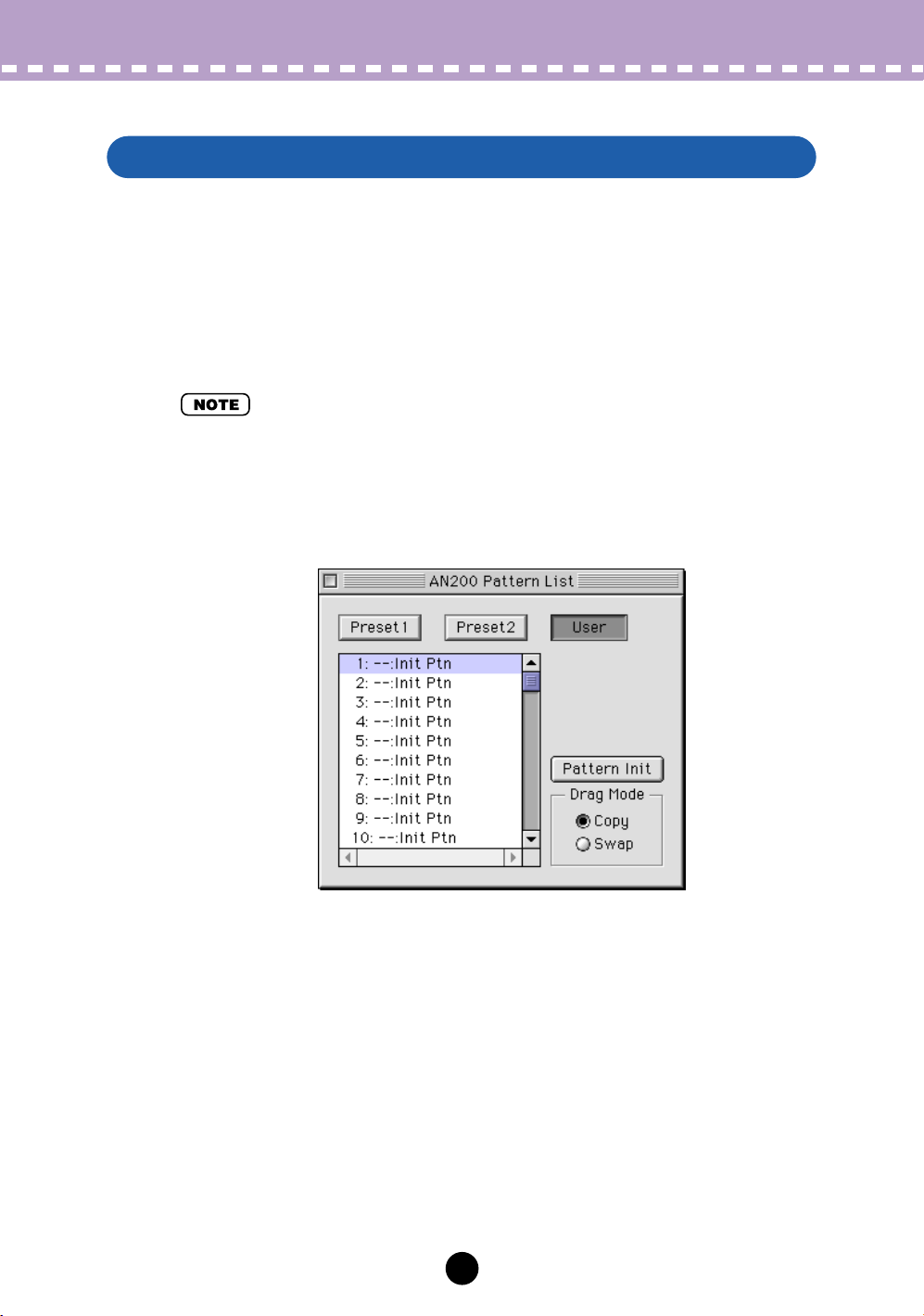
Select “AN200 Pattern List.”
Click the PATTERN button at the bottom right of the main control panel.
You can also quickly call up this dialog box by clicking any inactive part of the window pressing control key and clicking "AN200 Pattern List" in the pop-up menu. Or,
you can click "Edit" on the menu bar, then select "AN200 Pattern List."
x
Select the desired pattern.
Click on the desired pattern, then close the dialog box (click the close button) to
return to the main control panel window. (You can also do this by clicking anywhere
on the main control panel.)
3

Operations /
z
Select the desired pattern.
Refer to Selecting an AN200 Pattern.
x
Edit the pattern parameters as desired from the main control
panel.
The main window of the AN200 Editor provides a "virtual" control panel with knobs
and buttons, and lets you edit the patterns much as you would if you were operating
an actual hardware synthesizer.
c
Store the edited settings as a User pattern, then save it with
other edited patterns as an AN200 File.
Use the Store operation to store your newly edited pattern. Then use the Save
operation to save that edited pattern with other User patterns to an AN200 File.
Editing an AN200 Pattern
Editing an AN200 Pattern
Both the Store and Save operations are necessary to ensure that your pattern is
saved properly. Failing to do so would be roughly similar to writing a letter but not
putting it in an envelope and sending it. Make sure to execute both operations
when you wish to keep a pattern you’ve edited.
4
Operations /
Initializing an AN200 Pattern to the Default Settings
Initializing an AN200 Pattern to the Default Settings
This function allows you to reset all the parameters of the selected pattern to the factory
"initial pattern" default values. This gives you a "blank slate" from which you can create
your own pattern.
Keep in mind that this operation automatically erases all the settings of the selected pattern. If you wish to save the pattern for future recall, use the Store and Save functions.
z
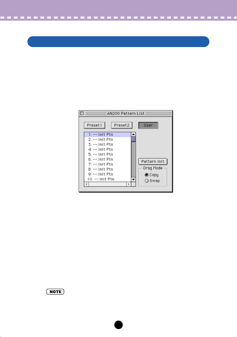
Select “AN200 Pattern List.”
Click the PATTERN button at the bottom right of the main control panel.
You can also quickly call up this dialog box by clicking any inactive part of the window pressing control key and clicking "AN200 Pattern List" in the pop-up menu. Or,
you can click "Edit" on the menu bar, then select "AN200 Pattern List."
x
Select the User bank and the desired pattern to be initialized.
Click on the User bank button, then click on the desired pattern.
c
Initialize the pattern.
Click the "Pattern Init" button in the dialog box. The specified pattern is initialized
and automatically selected for editing.
To return to the main control panel window, close the dialog box (click the close button). (You can also do this by clicking anywhere on the main control panel.)
• If you want to initialize all User patterns, then click on the "INIT ALL" button in the AN200
Librarian window.
5
Operations /
Storing an AN200 Pattern
Storing an AN200 Pattern
This operation lets you store your pattern edits as a User pattern.
• To ensure that your new pattern is available for future recall, make sure to also save the pattern (with other patterns) to an AN200 File.
z
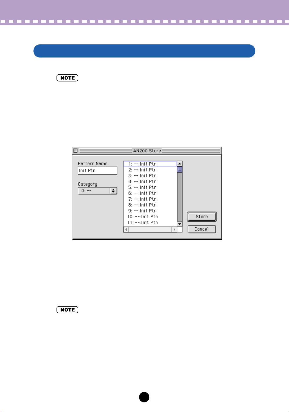
Select “AN200 Store.”
Click the red STORE button at the bottom right of the main control panel.
You can also quickly call up this dialog box by clicking any inactive part of the window pressing control key and clicking "AN200 Store" in the pop-up menu. Or, click
"Edit" on the menu bar, then select "AN200 Store."
x
Select the destination pattern.
Click on the desired pattern in the dialog box. Keep in mind that this pattern will be
erased and replaced with the newly edited pattern.
c
Store the pattern.
Click the "Store" button in the dialog box. The newly edited pattern is stored to the
selected location.
• This operation deletes the original pattern data at the destination.
• Keep in mind that this operation stores your pattern data only into the User pattern memory
of the AN200 Editor and sends the current pattern’s bulk data to the AN200. The current pattern bulk data will be lost if you select another pattern on the panel of the AN200. If you want
to select a pattern on the panel of the AN200, you should first transmit the User Pattern.
(Refer to Transmit AN200 Bulk Dump Data.) There is no need to transmit AN200 Bulk Dump
Data if you select a pattern in the Pattern List of the AN200 Editor, since the current pattern
bulk data is sent with that operation.
6
Operations /
Saving data to an AN200 File
Saving data to an AN200 File
Once you’ve edited an AN pattern and pattern to your satisfaction you can save it to an
AN200 File. Each AN200 File can contain up to 128 patterns, and these can be called
up at any time with the Open function. (Also see Calling Up Data from an AN200 File.)
Additional AN200 files (each with 128 User patterns) can be saved to floppy disks or
your hard disk drive --- giving you unlimited storage for your original patterns. For organizing the patterns in the AN200 Files, use the convenient AN200 Librarian function.
z
Select “Save AN200 File.”
Click "File" on the menu bar, then select "Save AN200 File".
• "Save AN200 File" can also be selected from the toolbar.
x
Select the desired folder, type in the file name, and click “Save.”
Calling Up data from an AN200 File (Open)
Once you’ve saved a set of User patterns and to one or more AN200 Files (see Saving
Patterns), you can instantly call up the desired patterns with this command.
To create a new AN200 File, use the New command.
z
Select “Open AN200 File.”
Click "File" on the menu bar, then select "Open AN200 File." Open AN200 File is
also available on the toolbar.
x
Select the desired folder and file name, then click “Open.”
• Keep in mind that this operation loads the User pattern data only into the User pattern memory of the AN200 Editor. After opening a file, if you want to play these Patterns on the AN200
separate from the AN200 Editor, you should transmit the User pattern data. (Refer to Trans-
mit AN Bulk Dump Data.) There is no need to transmit AN200 Bulk Dump Data if you select a
pattern in the Pattern List of the AN200 Editor, since the current pattern bulk data is sent with
that operation.
7
Parameters
Most of the AN200 Editor parameters for editing the AN200 patterns are contained in
the virtual "main control panel" screen. From this main panel, you can also jump to
other windows for controlling additional AN200 functions (such as the Control Matrix,
Free EG, and Step Sequencer).
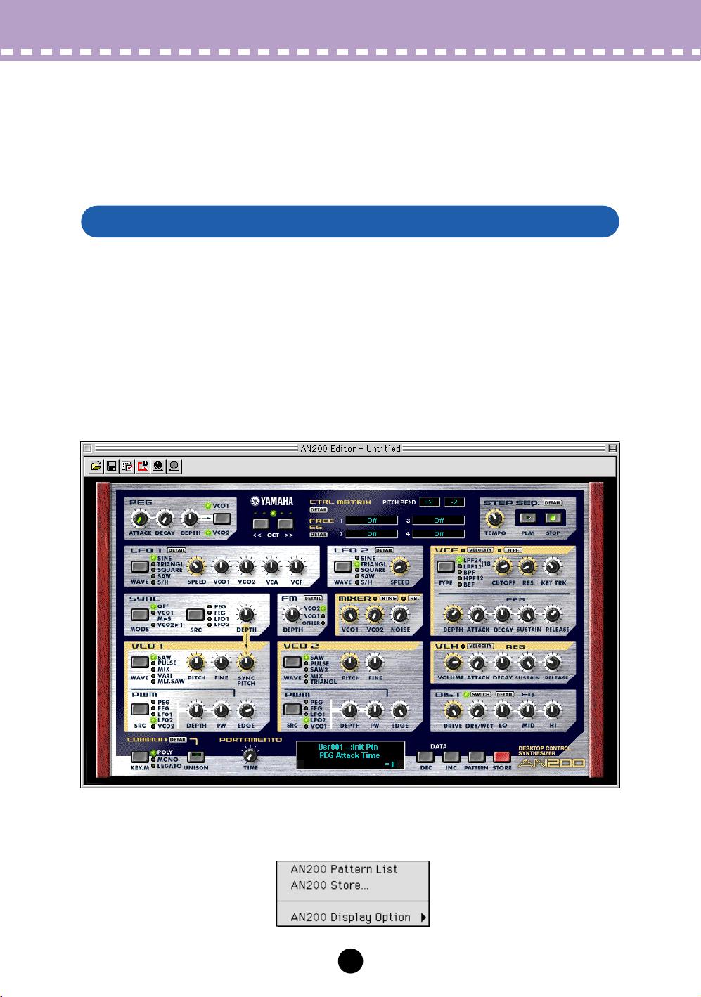
AN200 Editor Main Window
This is the main control panel for the AN200 Editor, and is comprised of the virtual
"panel" controls, the toolbar (at the top), and the virtual "LCD display" at the bottom.
The master menu (which includes AN200 Pattern List, Store, and the Display Option)
can also be selected from the main screen by clicking pressing control key any inactive
part of the front panel.
To jump to explanations for the desired parameter, click on the appropriate block in the
illustration below.
• Main Screen
• Master Menu
Click while pressing control key in an inactive area to call up the master menu.
8
Parameters /
AN200 Editor Main Window
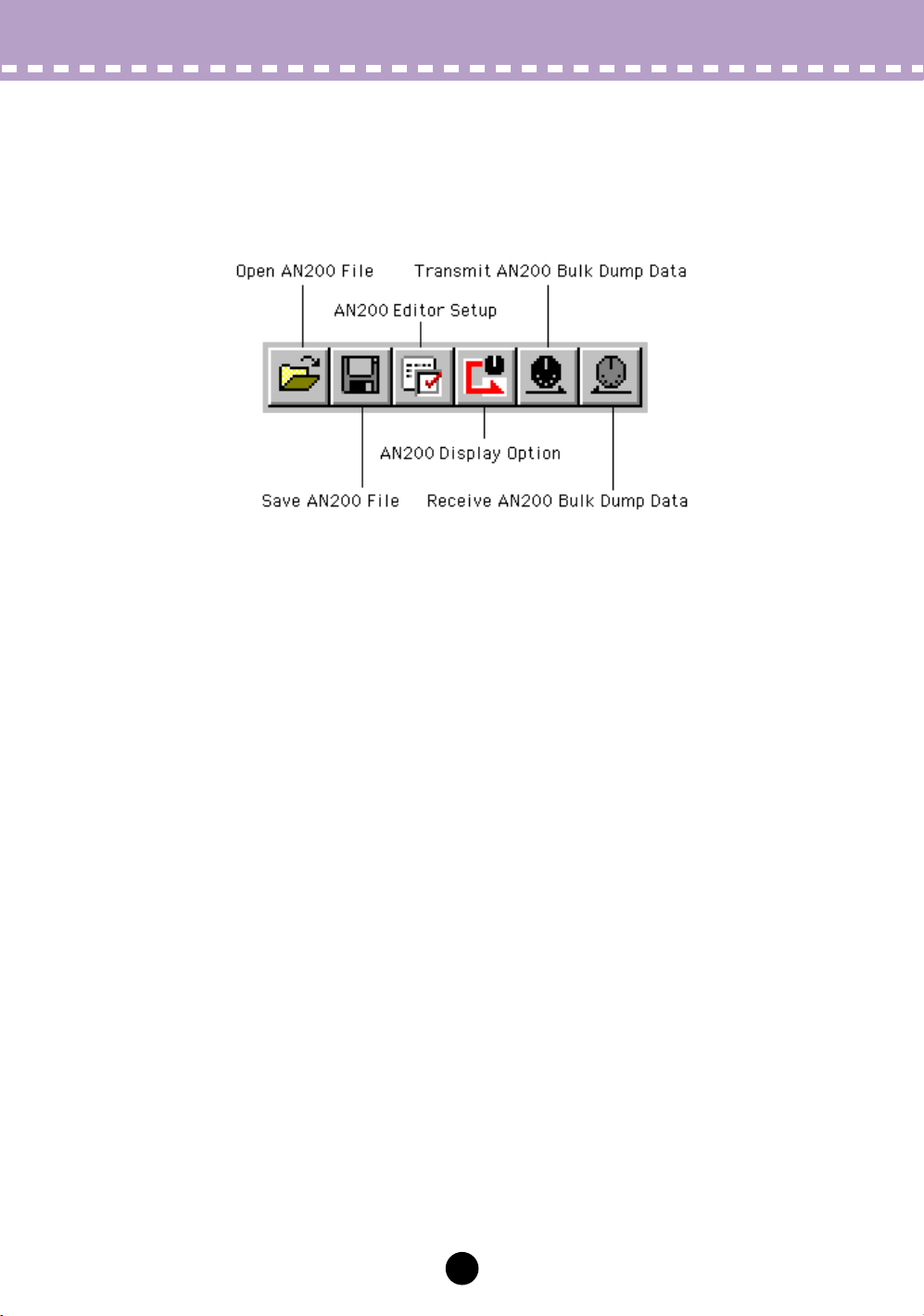
• Toolbar
The toolbar gives you quick access to some important functions and controls. These
buttons let you easily execute the desired function without having to select a menu or
leave the AN200 Editor window.
Open AN200 File
This is the same as the corresponding command in the File menu. It lets you select and
open an existing AN200 File. (See File Menus, Open AN200 File.)
Save AN200 File
This is the same as the corresponding command in the File menu. It lets you save the
current AN200 Editor settings as a parameter file for future recall. (See File Menus, Save
AN200 File.)
AN200 Editor Setup
This is the same as the corresponding command in the Setup menu. It lets you make
various important settings for configuring the AN200 Editor with the AN200. (See Setup
Menus, AN200 Editor Setup.)
Setup AN200 Display Option
This convenient feature lets you change the display of the main control panel to indicate
the current status of certain signal routings within the AN200. (See Setup Menus, AN200
Display Option.)
Transmit AN200 Bulk Dump Data
This is the same as the corresponding command in the Setup menu. It lets you transmit
the current AN200 Editor settings as MIDI data to the AN200. (See Setup Menus, Trans-
mit AN200 Bulk Dump Data.)
Receive AN200 Bulk Dump Data
This is the same as the corresponding command in the Setup menu. It lets you receive
the pattern from a connected AN200. (See Setup Menus, Receive AN200 Bulk Dump
Data.)
9
Parameters /
AN200 Editor Main Window
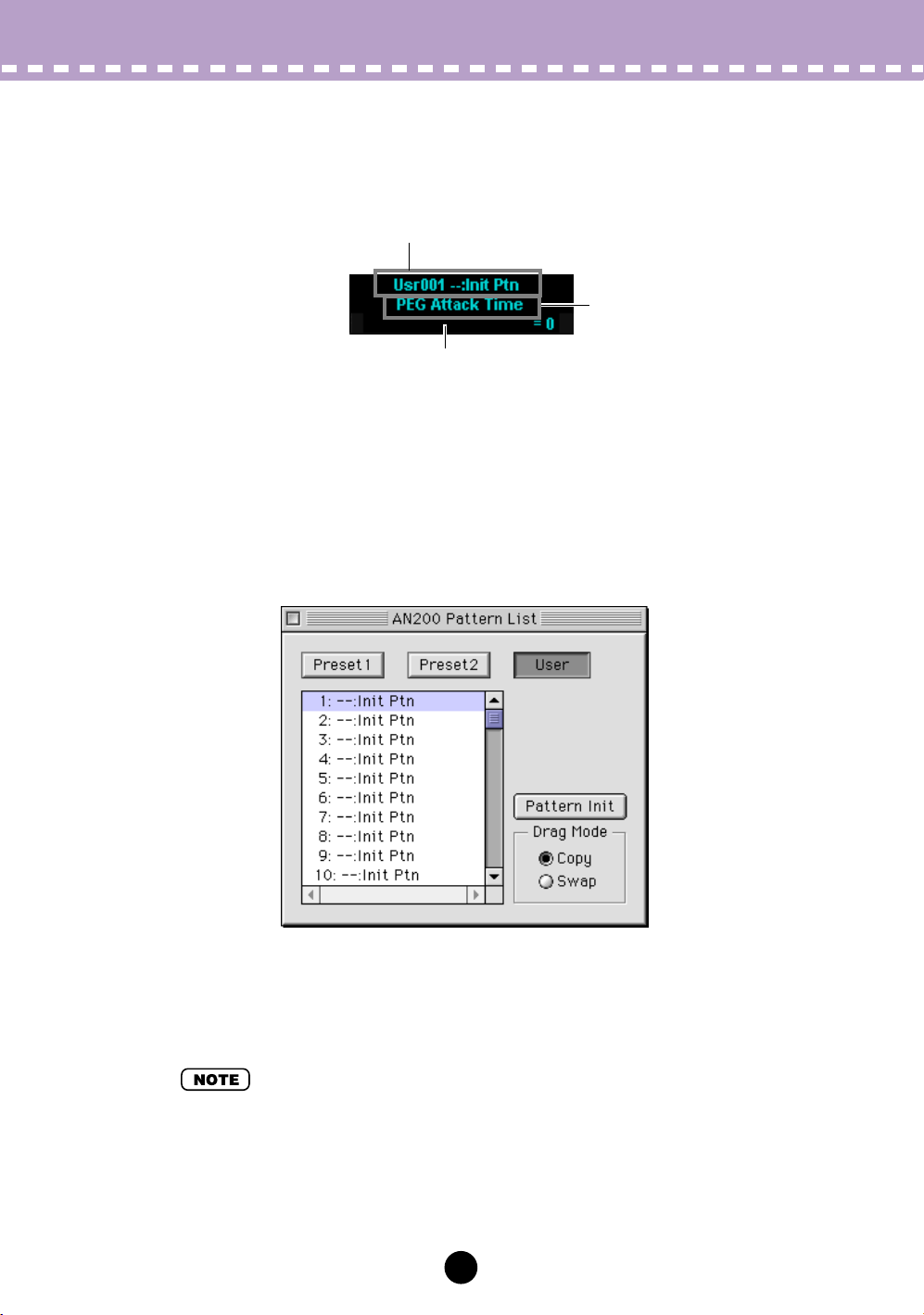
• LCD Display
This virtual "LCD" functions just like the display on an actual synthesizer's front panel.
Indicates the current pattern's bank/number as well as its category and name.
Full name of the currently
selected parameter.
Indicates the currently selected parameter's value or setting.
By clicking on this third line, you can also directly change the
value by typing it on the computer keyboard. (See Computer
Keyboard.)
• PATTERN Button
Pressing the PATTERN button calls up the AN200 Pattern List dialog box, allowing you
to select the desired pattern bank and pattern. It also allows you to reorganize the patterns of a selected bank, as well as initialize a pattern --- in other words, this resets all
parameters to their normal values, giving you a "blank slate" pattern to work with.
To select a bank, click on the desired bank button: Preset 1, Preset 2, or User. Each
bank contains 128 patterns. To select a pattern, click on the desired pattern in the
combo box. For a complete list of available patterns, see the Pattern List in the AN200
Owner's Manual.
• Each pattern name is preceded by a two-letter category abbreviation that indicates the general instrument group to which the pattern belongs. For example, "Ld" indicates "lead," "Ba"
indicates "bass," "Pd" indicates "pad," and so on.
10
Parameters /
AN200 Editor Main Window
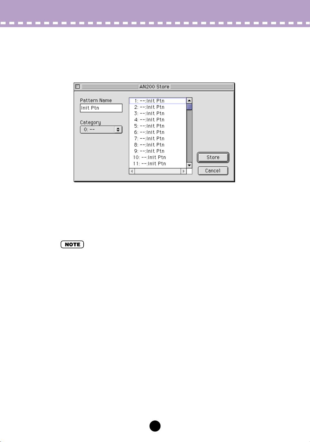
• STORE Button
Pressing the STORE button calls up the AN200 Store dialog box, allowing you to store
the desired pattern to the User bank. It also lets you enter a name and category
abbreviation for the pattern.
To name the pattern, click on the Pattern Name box, and type in the desired name. To
specify a category, click the Category combo box, and click the desired category
abbreviation. (The "0: ---" setting indicates no category.) To store the newly named
pattern, click "Store." For a complete list of available patterns and descriptions of the
category abbreviations, see the Pattern List in the AN200 Owner's Manual.
• Each pattern name is preceded by a two-letter category abbreviation that indicates the general instrument group to which the pattern belongs. For example, "Ld" indicates "lead," "Ba"
indicates "bass," "Pd" indicates "pad," and so on.
11
 Loading...