

Yamaha AMP EDITOR v.1.3 User Manual

Amp Editor
Version 1.3
EN
Owner’s Manual

What is Amp Editor?
Amp Editor is software that enables network-compatible amplifiers (such as the TXn series and XMV series);
amp control devices (the ACD1); and compatible amplifiers connected to amp control devices to be assembled
into a system, and then be monitored and controlled from a computer.
Amp Editor allows centralized monitoring and control of multiple connected devices.
Special Notices
The software and this manual are the exclusive copyrights of Yamaha Corporation.
Use of the software and this manual is governed by the license agreement which the purchaser fully agrees to
upon breaking the seal of the software packaging. (Please read carefully the Software Licensing Agreement at
the beginning of Installation Guide before installing the application.)
Copying of the software or reproduction of this manual in whole or in part by any means is expressly forbid-
den without the written consent of the manufacturer.
Yamaha makes no representations or warranties with regard to the use of the software and documentation and
cannot be held responsible for the results of the use of this manual and the software.
The illustrations and screens as shown in this manual are for instructional purposes only, and may appear
somewhat different from those on your instrument.
For information on modification of system software, certain functions, or specifications due to version update
of the application, please visit the following website:
http://www.yamahaproaudio.com/
Windows is a registered trademark of Microsoft
®
Corporation in the United States and other countries.
The company names and product names in this manual are the trademarks or registered trademarks of their
respective companies.
Amp Editor Owner’s Manual
2

Contents
Chapter 1 Preparing for operation 4
Terms............................................................................................ 6
Installing and setting up Amp Editor ............................................. 7
Chapter 2 An overview of Amp Editor 8
Main Panel window ....................................................................... 9
Tree View window ....................................................................... 10
Detail View window ..................................................................... 11
Projects....................................................................................... 12
Chapter 3 Setup 15
Device ID settings .......................................................................15
IP address settings......................................................................17
Chapter 4 Basic operations in Amp Editor 23
Chapter 5 Main panel window 33
Objects in the window and their function .................................... 33
Menus in the main panel window................................................ 36
Preferences ................................................................................. 39
Event Log ....................................................................................43
Device Information ...................................................................... 49
Scene Manager ........................................................................... 51
Alert Setup .................................................................................. 55
Word Clock (TXn only)................................................................ 59
Speaker Processor Library Manager (TXn only)..........................61
Clock ........................................................................................... 66
Language (TXn only)................................................................... 67
GPI (ACD1 only).......................................................................... 68
Utility........................................................................................... 76
IP Address................................................................................... 84
IP Control Port No....................................................................... 85
Firmware Update (Updating the internal firmware) ..................... 86
Scene Link Manager (for devices other than XMV) ..................... 89
Network Setup.............................................................................91
Synchronization (Synchronization with devices) .........................94
Custom Control Panel Manager...................................................96
System View Creator ...................................................................98
Speaker Processor Library Converter........................................ 101
Chapter 6 Tree View window 102
Tree structure............................................................................104
Operations in the Tree View window .........................................105
Chapter 7 Detail View window 114
Device Detail View .....................................................................115
Chapter 8 Device Properties window 127
Chapter 9 Signal Path View window (TXn only) 141
Opening the component editor .................................................. 142
Switching a function or signal on/off.........................................142
Chapter 10 Component editor (TXn only) 143
Objects in the window and their function ..................................143
Operation mode and Design mode ............................................148
Context menu ............................................................................149
Snap .......................................................................................... 150
Library.......................................................................................152
Parameter link / Component link ...............................................156
Component guide ......................................................................162
Chapter 11 Custom control panels 176
Creating a new custom control panel ........................................177
Operation mode and Design mode ............................................177
Context menu ............................................................................178
Tool palette................................................................................180
Placing controls......................................................................... 183
Editing controls ......................................................................... 187
Control properties .....................................................................189
Changing the tab order..............................................................201
Size and background settings for a custom control panel .........202
Full-screen display..................................................................... 203
Appendix 204
Alert message list ......................................................................204
Troubleshooting ........................................................................210
Amp Editor Owner’s Manual
3

Chapter
1
Preparing for operation
As of August 2013, the following devices and functions can be used with Amp Editor.
Network-compatible amplifiers
• TXn series (subsequently called TXn): TX6n, TX5n, TX4n
• XMV series (subsequently called XMV) : XMV4140, XMV4280, XMV8140, XMV8280, XMV4140-D,
XMV4280-D, XMV8140-D, XMV8280-D
Amp control devices
•ACD1
Amplifiers compatible with amp control devices
• XP series (subsequently called XP) : XP7000, XP5000, XP3500, XP2500, XP1000
• XM series (subsequently called XM) : XM4180, XM4080
• XH series (subsequently called XH) : XH200
• PC-1N/PC-N series (subsequently called PC-N) : PC9501N, PC6501N, PC4801N, PC3301N, PC2001N,
PC9500N, PC4800N, PC3300N
• Tn series (subsequently called Tn) : T5n, T4n, T3n
* For the most recent information, refer to the following URL.
http://www.yamahaproaudio.com/
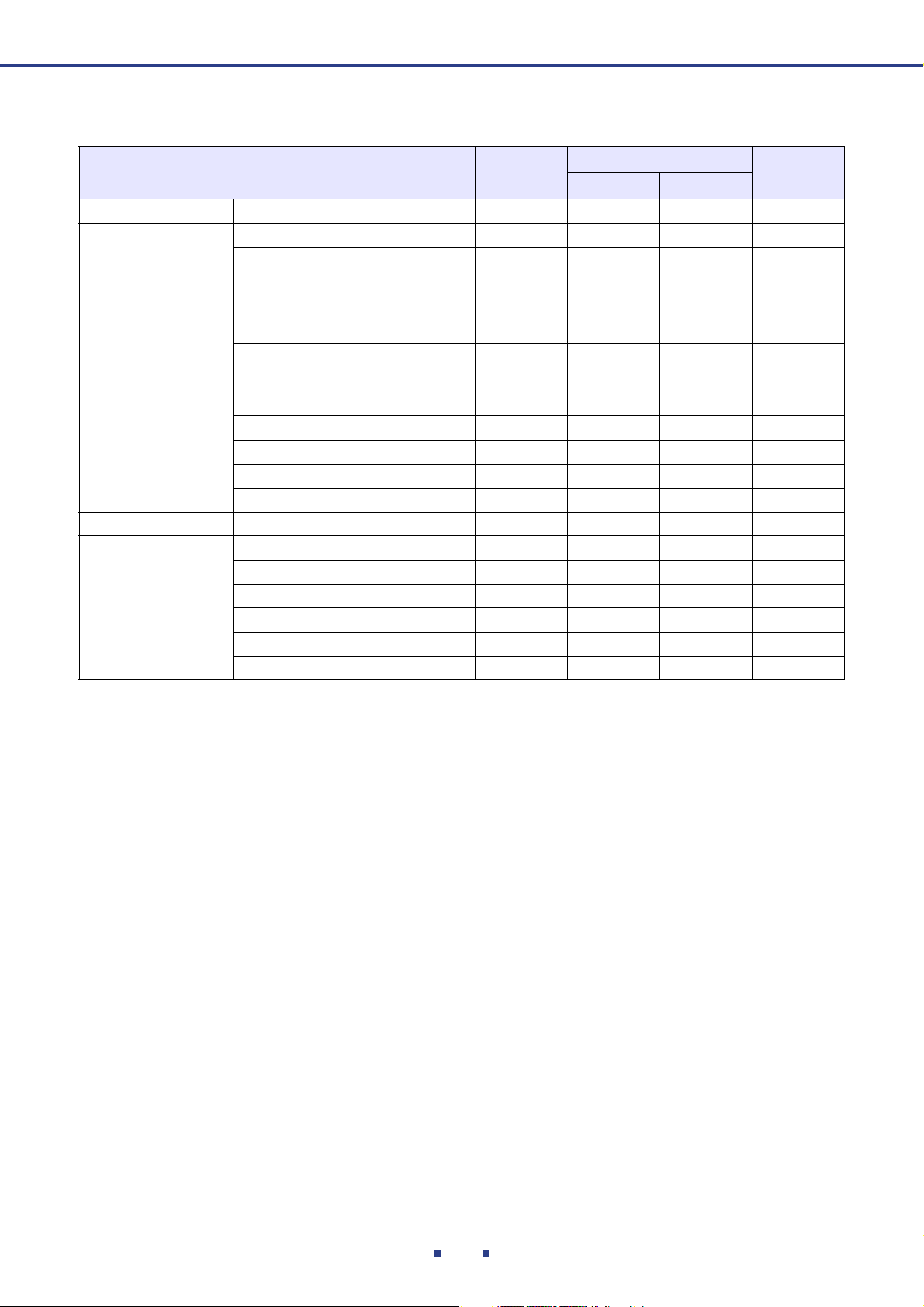
Functions available on each device
Functions TXn
Event Log 43
Device Information 49
Scene Manager — 51
Scene Link Manager — 89
Alert Setup — 55
Word Clo ck ——59
Clock 66
Language ——67
GPI — — 68
Utility 76
IP Address 84
IP Control Port No.
Firmware Update 86
Recovery Update 88
Synchronization 94
Custom Control Panel Manager 96
System View Creator 98
Speaker Processor Library Manager
Global Link 158
Local Link ——159
——61
ACD1
(Tn/PC-NXP/XM/XH)
XMV Page
(Display only)
85
: Available
— : Not available
Amp Editor Owner’s Manual
4
Chapter 1 Preparing for operation
Parameters that can be monitored/controlled
Parameter TXn
Signal Path View* Component parameter editing ———
Analog Input
Slot Input
Speaker Output
Slot Output Level meter ———
General
Level meter ——
Mute switching ———
Pre Input meter ———
Mute switching ———
Level meter (output voltage)
Power meter ——
Impedance meter ——
Attenuation operations —
Attenuator’s Link switching ——
Mute switching
Solo switching —
Polarity (phase reversal) switching ** —
Power Standby/On operations
Temperature meter ——
Protection monitor
Amp Output mode detection —
Amp Output mode switching ———
Fan meter ———
Tn/PC-N XP/XM/XH
ACD1
XMV
: Available
— : Not available
* For more about the Signal Path View, refer to page141.
** Polarity switching for the TXn is performed in the Signal Path View.
Amp Editor Owner’s Manual
5
Chapter 1 Preparing for operation
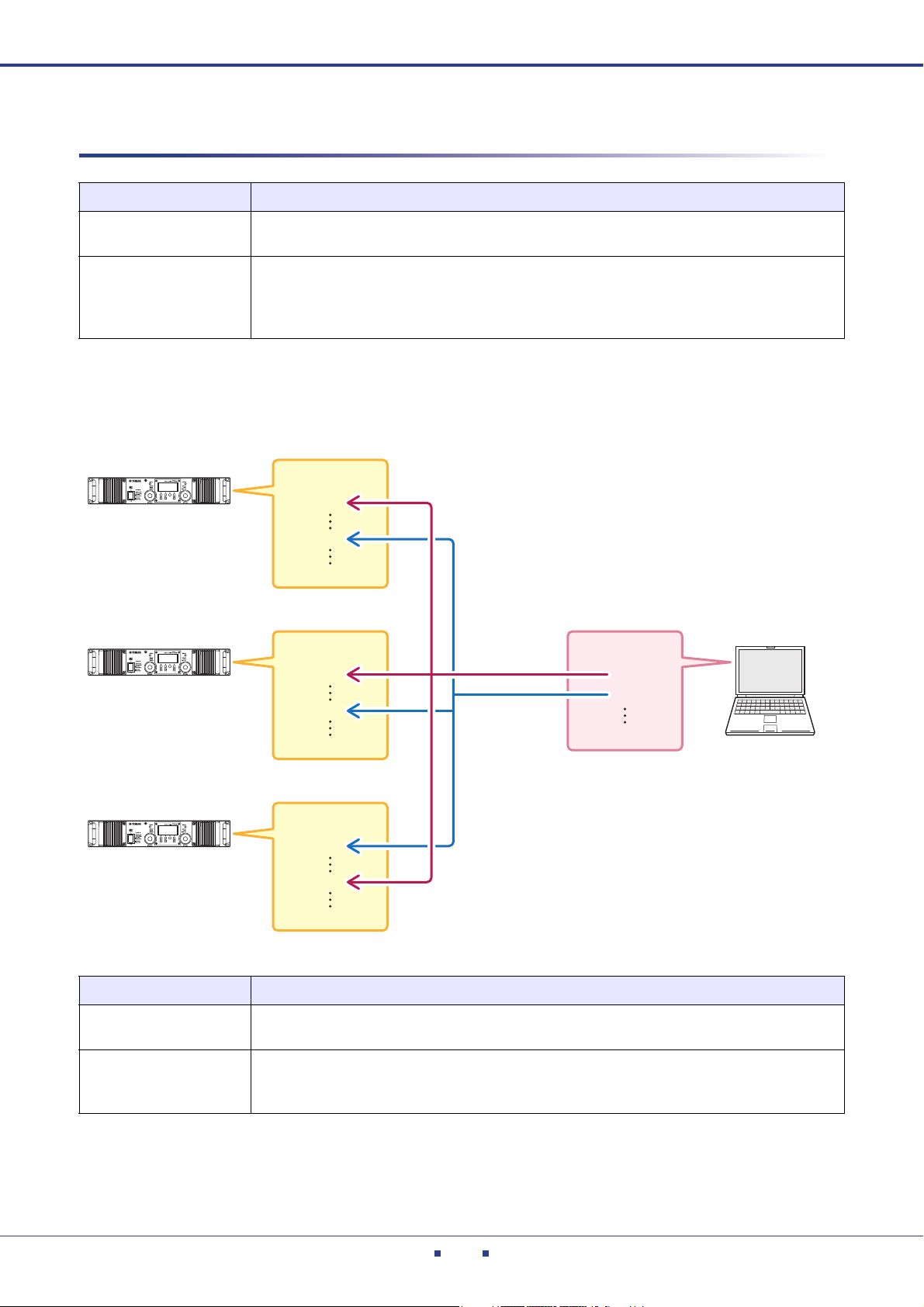
Amplifier A
Amplifier B
Amplifier C
Scene
Scene
Scene
Recalle
Amp Editor
Scene link
Terms
Term Definition
Workspace
Online/Offline
The set of devices that can be simultaneously monitored and controlled by Amp Editor is called
a workspace.
“Online” is the state in which the devices are connected to the computer and network, and are
synchronized with Amp Editor so that they can be monitored and controlled. “Offline” is the
state in which the devices and computer are not physically connected, or connected but not
synchronized.
01
10
01
04
01
02
Scene
Scene link
01
15
Term Definition
A settings for each amplifier is called a “scene.” By recalling a scene, the saved settings can be
immediately applied to the amplifiers.
Settings for simultaneously recalling scenes for multiple amplifiers within a workspace are
called a “scene link.” By recalling a scene link, scenes can be simultaneously recalled for multiple amplifiers. Scene links can be created and recalled using Amp Editor.
Amp Editor Owner’s Manual
6

Chapter 1 Preparing for operation
Installing and setting up Amp Editor
In order to use Amp Editor to monitor and control your system, you must install Amp Editor in your computer,
and then specify IP addresses and IDs for the computer and devices.
For details on installing Amp Editor, refer to the “Amp Editor Installation Guide.” For details on making settings
in your computer, refer to “Setup” (page 15).
For details on making settings in your devices, refer to the owner’s manual or reference manual for each device.
You can download these manuals from the Yamaha Pro Audio website (http://www.yamahaproaudio.com/down-
loads/)
Amp Editor Owner’s Manual
7
Chapter
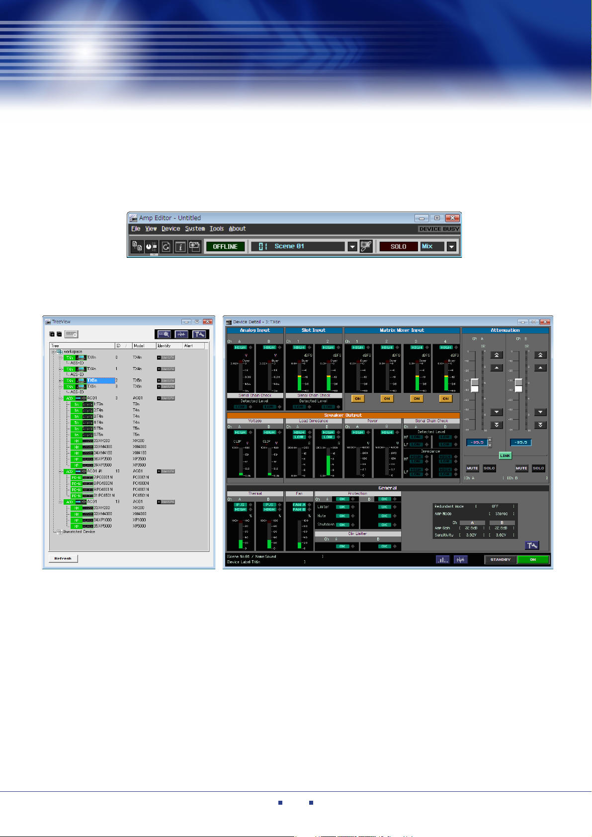
Main Panel window
Tree View window Detail View window
2
Broadly speaking, Amp Editor consists of three windows: the Main Panel window, the Tree View window,
and the Detail View window.
An overview of Amp Editor
Amp Editor Owner’s Manual
8

Chapter 2 An overview of Amp Editor
NOTE
Menu bar
Toolbar
Main Panel window
The Main Panel window is the main window of Amp Editor.
• You can open a project file (filename extension .yae) by dragging and dropping it onto the Main Panel
window.
Menu bar
Here are the functions that can be executed by Amp Editor, grouped by category.
Click to see a list of functions. For details, refer to “Main Panel window” (page 33).
Too lbar
This area contains buttons for the most frequently used functions of Amp Editor, and also shows the current sta-
tus. For details, refer to “Main Panel window” (page 33).
Amp Editor Owner’s Manual
9
Chapter 2 An overview of Amp Editor
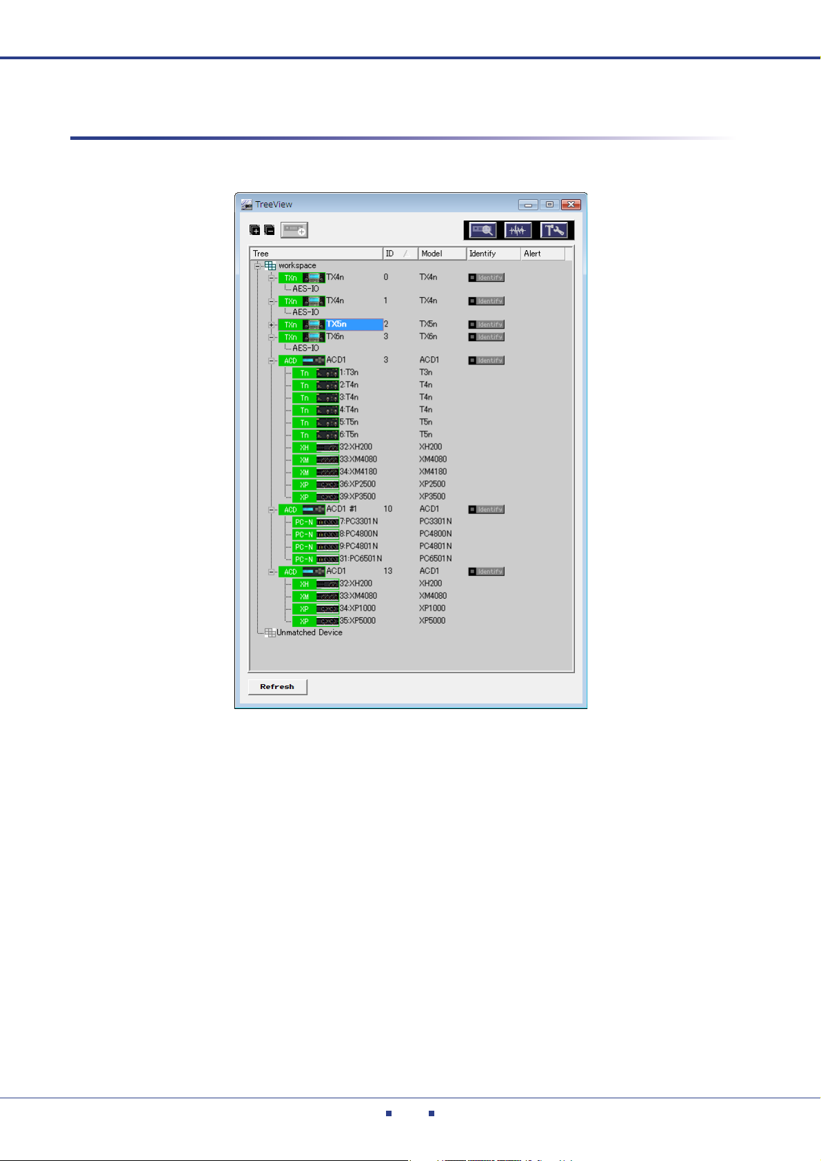
Tree View window
The Tree View window is a hierarchical view of the connection status of the devices connected to the network.
By double-clicking an icon shown in this window, you can access the Detail View window to see detailed infor-
mation. For details, refer to “Tree View window” (page 102).
Amp Editor Owner’s Manual
10
Chapter 2 An overview of Amp Editor
Detail View window
The Detail View window lets you monitor/control the amplifier that is specified in the Tree View window.
The following four types of screen are shown.
Screen name Content
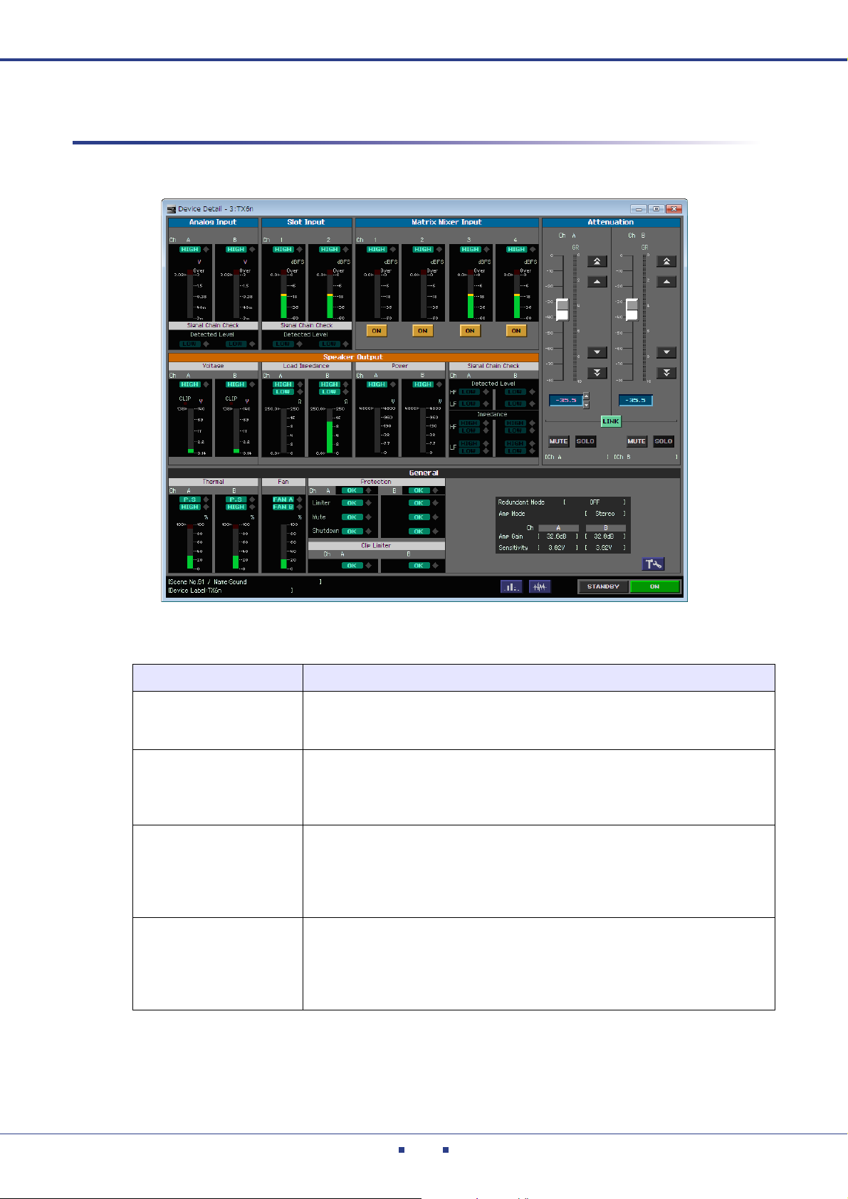
Device Detail View
(page 115)
Signal Path View
(TXn only) (page 141)
Device Properties
(page 127)
I/O Card Editor
(TXn only) (page 173)
This will appear when you double-click an amplifier icon. Here you can monitor
the amplifier’s status such as its level meters, or control the attenuation and Mute
status of an amplifier.
This will appear when you click the [Signal Path View] button in the TXn’s Device
Detail and the Tree View window, or when you choose [Show] [Signal Path
View] from the context menu that appears when you right-click the TXn icon. Here
you can edit the parameters of the TXn’s components.
This will appear when you click the [Device Properties] button in the Tree View
window and the Detail View window, or when you choose [Show] [Device Properties] from the context menu that appears when you right-click the amp icon.
Here you can make various settings, such as the amplifier’s output mode, gain/
input sensitivity, and alerts/protection settings.
This will appear when you choose [Show] [I/O Card Editor] from the context
menu that appears when you right-click the TXn or I/O card icon. This lets you
specify the input/output mode of a digital I/O card inserted in the slot.
You cannot select I/O Card Editor for cards other than a digital I/O card (e.g., an
AD card or a DA card).
Amp Editor Owner’s Manual
11
Chapter 2 An overview of Amp Editor
Projects
A system constructed by Amp Editor is saved in a folder as a “project.”
A project contains settings for workspace, components, and parameters.
Only one project can be opened at a time; when you open a different project, the currently-open project will be
closed.
The commands for opening, creating, or saving a project are found on the [File] menu of the main panel window.
Creating a new project
Here’s how to create a new project.
1. In the main panel window, click [File] menu [Name].
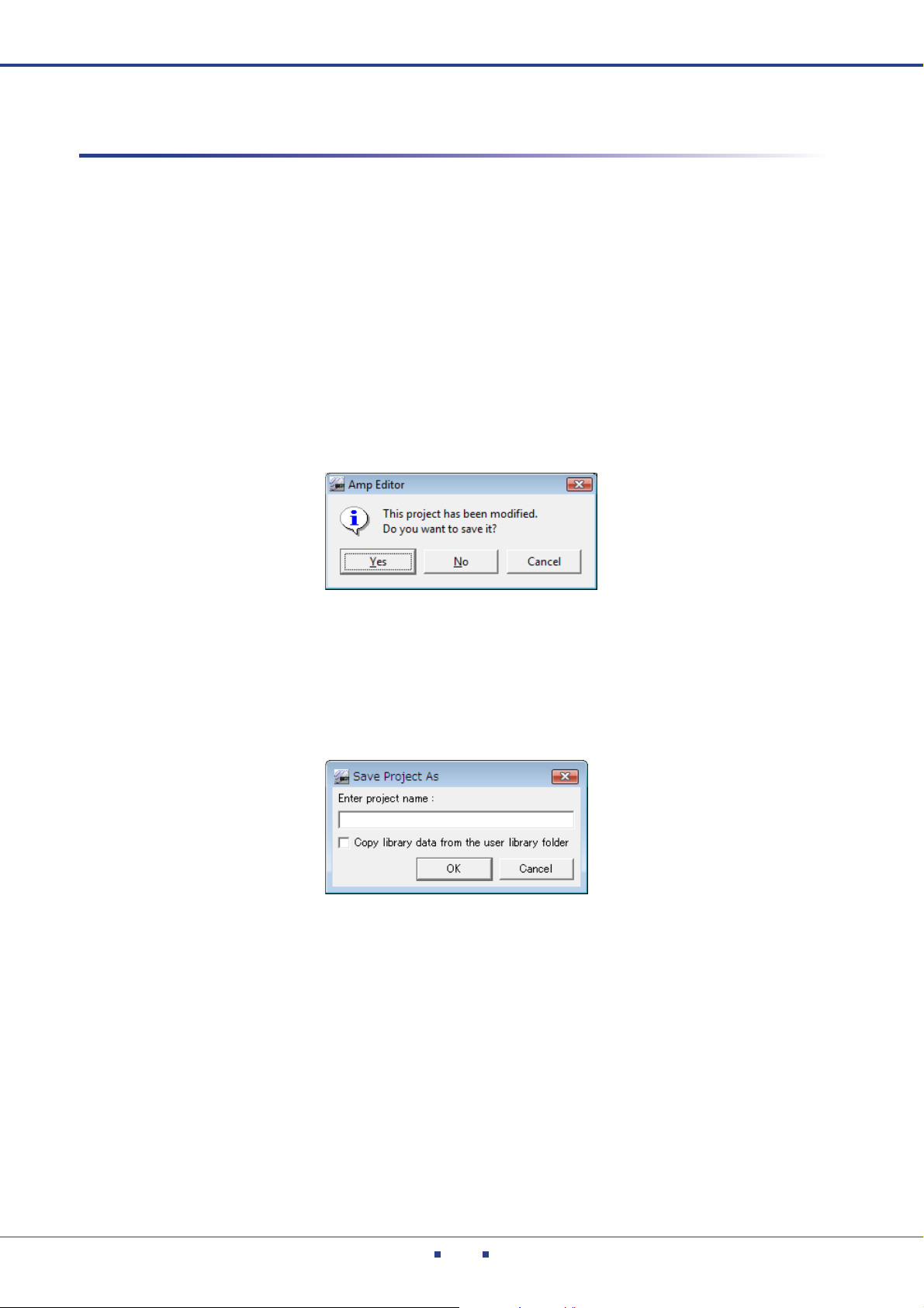
The currently-open project will be closed when you create a new project, so a dialog box will ask whether
you want to save the current project.
2. Click [Yes] if you want to save the project, or [No] if you don’t want to save it.
If you click [Yes], the “Project Save As” dialog box will appear if the project has never been saved
before. Enter the name under which you want to save the project, and click the [OK] button. In the folder
selection dialog box that will then appear, select or create the folder in which to save the project, and click
the [OK] button.
The new project will be created.
Saving a project
In Amp Editor, projects are saved in units of folders.
To save a project, use the main panel window [File] menu [Save] or [Save As...] command. The [Save] command
will overwrite the previously-saved version of the project. The [Save As...] command will save the project under
a different name.
Amp Editor Owner’s Manual
12
Chapter 2 An overview of Amp Editor
NOTE
Saving a project
1. In the main panel window, click [File] menu [Save].
The currently-open project will be overwritten.
Save as a specified name
The main panel window [File] menu [Save As...] command lets you save the currently-open project with
the name you specify. If you’re saving for the first time, a project will be created. If the project has already
been assigned a name and saved, it will be saved as a different project.
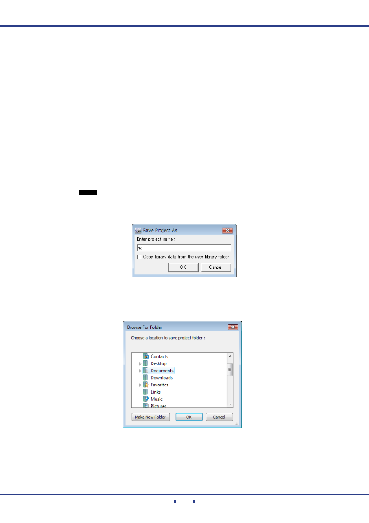
1. In the main panel window, click [File] menu [Save As...].
The “Save Project As” dialog box will appear.
When saving the library file with a project, select the [Copy library data from the user library folder.]
check box. If you click the [OK] button, the [Select Library] dialog box will appear. This dialog box
shows the library files are saved to the User Library folder. Select the library file to be copied to the proj-
ect folder, and then click the [OK] button.
• If a library file of the same name already exists in the destination for the project, the dialog box
will ask whether you want to overwrite, or save the library file as a specified name with numbers. When you save it as a specified name with numbers, a list of the library files that were
most recently saved (starting with the same letters as that specified name) will be displayed.
2. Enter the name under which you want to save the project, and click the [OK] button.
The folder selection dialog box will appear.
3. Select or create the folder in which you want to save the project, and click the [OK] but-
ton.
The project will be created.
Amp Editor Owner’s Manual
13
Chapter 2 An overview of Amp Editor
Recently used projects
NOTE
Opening a project
Here’s how to open a previously-saved project.
The currently-open project will be closed when you open a new project, so a dialog box will ask whether you
want to save the current project.
[Open] command
1. In the main panel window, click [File] menu [Open].
The folder selection dialog box will appear.
2. Select the folder of the project that you want to open.
3. Click the [OK] button.
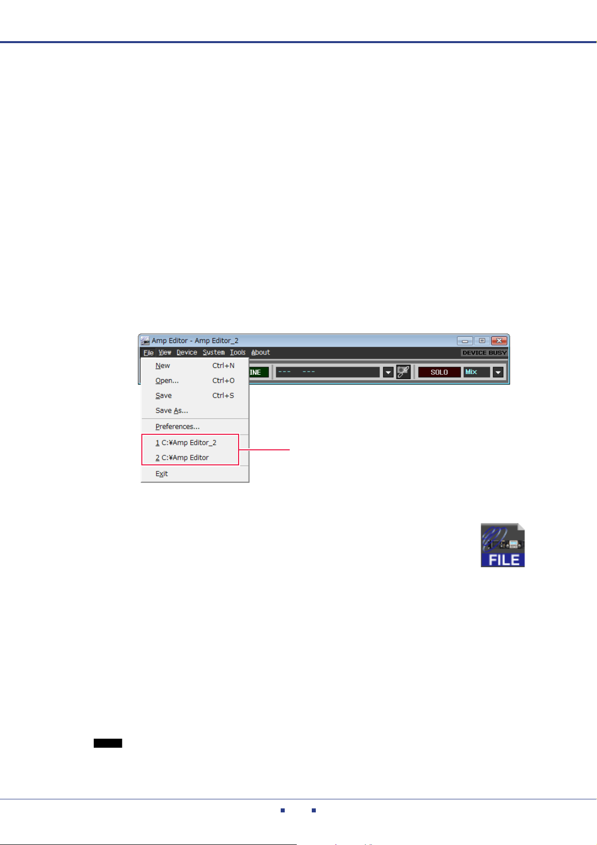
Open a project from [Recently used projects]
The [File] menu of the main panel window will list the recently used projects.
You can open a project by clicking its project name.
Double-click the icon of a project file
You can open a project by double-clicking the icon of the project file (file name
extension .yae) in a project folder. If Amp Editor is not running, Amp Editor will
start up and the project will be opened.
Drag and drop a project file onto the main panel window
You can open a project by dragging and dropping a project file (or its shortcut) from a project folder into the
main panel window.
Closing a project
Amp Editor is not able to open multiple projects simultaneously. To close the currently open project, either create
a new project or open a different project.
• When copying a project to another folder or another computer, you must copy the entire project folder.
Amp Editor Owner’s Manual
14
Chapter
NOTE
NOTE
NOTE
3
To use Amp Editor to monitor and control your equipment, you must first specify the IP address for your
computer and devices, and the ID for your devices.
• A Device ID is a unique number assigned to each device to be recognized by the network. Depending on the
Setup
product, the Device ID might be represented differently. For example, on the TXn or ACD1, it is called “Device
ID” and expressed in decimal numbers. On the XMV, it is called “UNIT ID” and expressed in hexadecimal numbers. In this manual, the term Device ID or UNIT ID will be used depending on the product.
Device ID settings
Here’s how to set the Device ID so that Amp Editor can distinguish each unit. If multiple devices exist on the
same network, you must assign a unique ID to each device.
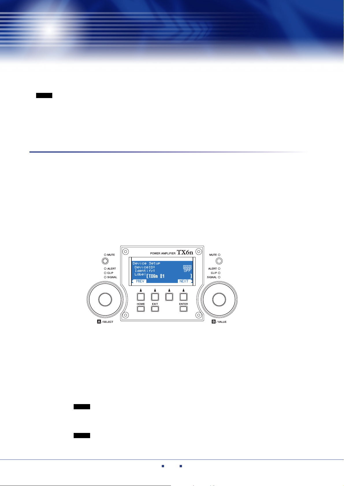
For the TXn
Power-on the TXn.
1.
After approximately ten seconds, the unit’s front panel display will show the HOME screen.
2. On the front panel of the unit, hold down the [ENTER] button for one second or longer.
The Device ID setting screen will appear.
3. Use encoder B on the front panel of the unit to select the Device ID. You can select a
value in the range of 0–255.
If multiple ACD1 and/or TXn units are connected to a single network, set each unit to a different Device
ID.
4. On the unit’s front panel, press the [ENTER] button.
The value you specified will be applied to the unit.
• The value you edit will blink until you press the [ENTER] button. If you move to a different
screen while the value is still blinking, the change you made will not be applied.
5. Repeat steps 1–4 to specify the Device ID for each connected TXn unit.
• You can also change the Device ID on Amp Editor’s [Change Device ID] dialog box (page 108)
after the devices are synchronized with Amp Editor.
Amp Editor Owner’s Manual
15
Chapter 3 Setup
NOTE
NOTE
NOTE
NOTE
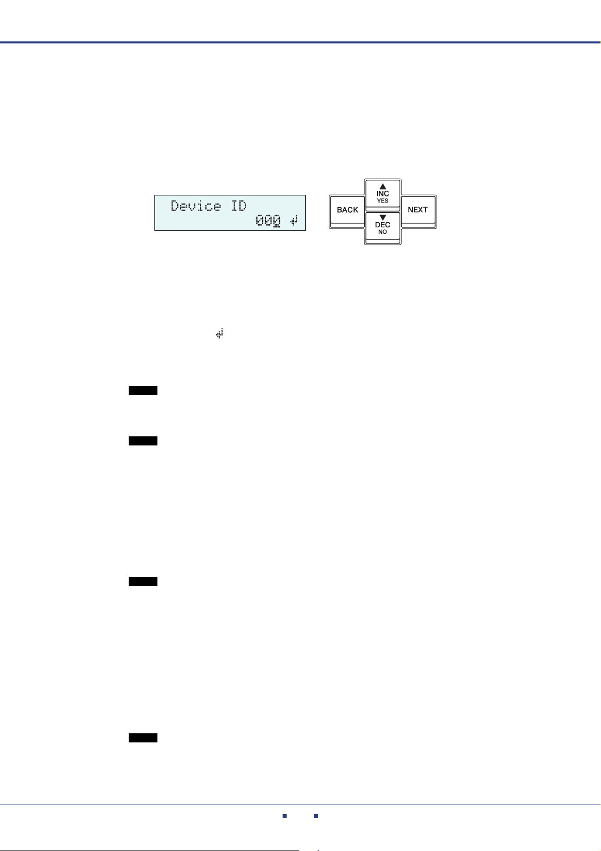
For the ACD1
Power-on the ACD1.
1.
After approximately ten seconds, the unit’s front panel display will show the HOME screen.
2. On the front panel of the unit, hold down the [BACK] button for one second or longer.
The Device ID setting screen will appear.
3. Use the [sINC/YES] or [tDEC/NO] button on the front panel of the unit to select the
Device ID. You can select a value in the range of 0–255.
If multiple ACD1 or TXn units are connected to a single network, set each unit to a different Device ID.
4. Press the front panel [NEXT] button.
The cursor moves to .
5. Press the front panel [sINC/YES] button.
The value you specified will be applied to the unit.
• If you move to a different screen without pressing the [sINC/YES] button, your change will not
be applied.
6. Repeat steps 1–5 to specify the Device ID for each connected ACD1 unit.
• You can also change the Device ID on Amp Editor’s [Change Device ID] dialog box (page 108)
after the devices are synchronized with Amp Editor.
For the XMV4140/XMV4280/XMV8140/XMV8280
Power-off the XMV.
1.
2. Use the DIP switches (1–3) to specify the upper digit, and use the rotary switch to specify
the lower digit to select the UNIT ID value from a maximum of 127 combinations in the
range of 01 through 7F (127).
• To change the switch settings, turn off the power to the unit. If you change the settings while the
power is on, the change will not be effective until you turn the unit off and then on.
• Do not use “00” as the UNIT ID.
For the XMV4140-D/XMV4280-D/XMV8140-D/XMV8280-D
Power-off the XMV-D.
1.
2. Use the rotary switch (HIGH) to specify the upper digit, and use the rotary switch (LOW)
to specify the lower digit to select the UNIT ID value from a maximum of 254 combinations in the range of 01 through FE (254).
• Do not use “00” or “FF” as the UNIT ID.
• To change the switch settings, turn off the power to the unit. If you change the settings while the
power is on, the change will not be effective until you turn the unit off and then on.
Amp Editor Owner’s Manual
16

Chapter 3 Setup
NOTE
IP address settings
Here’s how to set the IP address of the computer and of the devices so that Amp Editor can communicate with the
devices.
Accessing the Control Panel
The way to access the Control Panel will depend on your operating system.
Windows XP / Vista / 7
Select [Start] [Control Panel].
Windows 8
1. In the Start screen, click [Desktop].
The desktop will appear.
2. Move the cursor to the upper right or lower right corner of the desktop.
The Charms bar will appear.
3. Select [Settings] [Control Panel].
IP address settings for the computer
• Unless you have a specific need to do otherwise, you should set the IP address to a private address
(192.168.0.2–192.168.255.253). If you need to specify a global address, please consult your network
administrator before doing so.
• Do not connect to the same network as an audio network such as EtherSound or CobraNet. If you do
so, communication may be interrupted, and the system may stop operating correctly.
• The explanation that follows will assume that the Windows network connection is named “Local area
connection.” The name may differ according to your environment.
If the control panel appears as category view, switch the view as follows:
For Windows XP
Click [Switch to Classic View] in the upper left of the control panel.
For Windows Vista
Click [Classic View] in the upper left of the control panel.
For Windows 7 / 8
Click [View by : Category] in the upper right of the control panel, and select “Large icons” or “Small icons”.
Amp Editor Owner’s Manual
17
Chapter 3 Setup
NOTE
NOTE
Windows Vista / 7 / 8 users
1. Access the Control Panel, then click or double-click [Network and Sharing Center] or
[View network status and tasks].
The “Network and Sharing Center” is displayed.
2. Click [Manage network connection] or [Change adapter settings] from the “Tasks” list
located in the left side of “Network and Sharing Center” window, then double-click [Local
Area Connection].
The “Local Area Connection Status” dialog box will be displayed.
3. Click [Properties].
The “Local Area Connection properties” dialog box will be displayed.
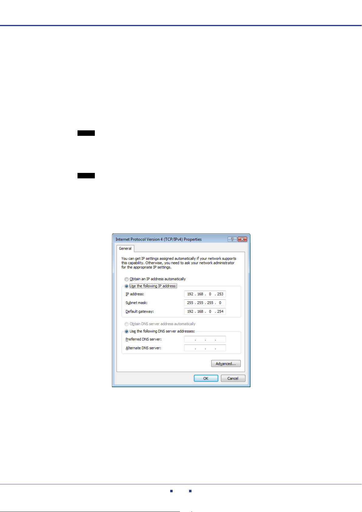
4. Select [Internet Protocol Version 4(TCP/IPv4)], then click [Properties].
The “Internet Protocol Version 4(TCP/IPv4) Protocol” dialog box will be displayed.
• The “User Account Control” dialog box may appear. Click [Continue].
• If the “Local Area Connection properties” dialog box appears, skip ahead to step 4.
• The “User Account Control” dialog box may appear. Click [Continue].
5. Select [Use the following IP address], and set the [IP address] and [Subnet mask].
We recommend an [IP address] value of “192.168.0.253” and a [Subnet mask] value of “255.255.255.0”.
6. Click the [OK] button to close the dialog box.
Amp Editor Owner’s Manual
18
Chapter 3 Setup
Windows XP users
1. Chose [Control Panel] [Network connections], and double-click [Local area connec-
tions].
The “Local area connection status” dialog box will appear.
2. In the [General] tab, click [Properties].
The “Local area connection properties” dialog box will appear.
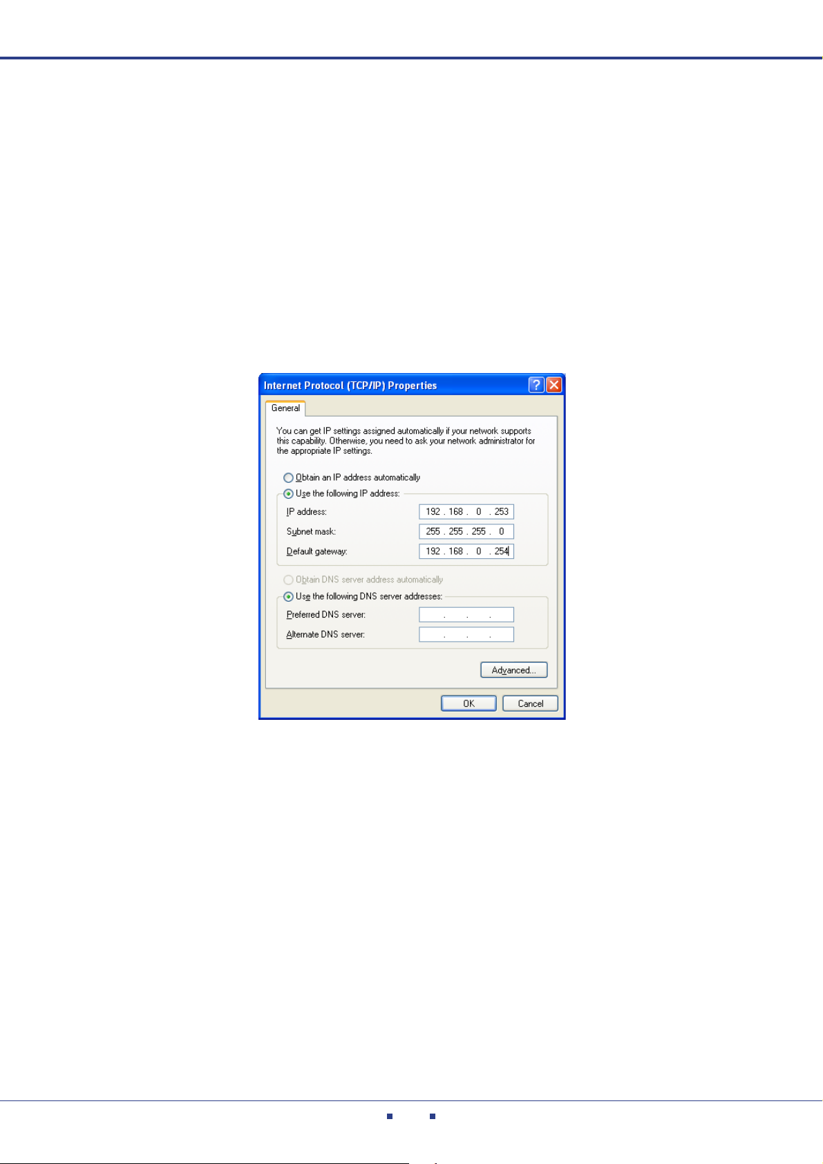
3. In the [General] tab, double-click [Internet protocol (TCP/IP)].
The “Internet protocol (TCP/IP) properties” dialog box will appear.
4. Select [Use the following IP address], and set the [IP address] and [Subnet mask].
We recommend an [IP address] value of “192.168.0.253” and a [Subnet mask] value of “255.255.255.0”.
5. Click the [OK] button to close the dialog box.
Amp Editor Owner’s Manual
19
Chapter 3 Setup
Setting the device IP address (example for a TXn or ACD1)
On a TXn or ACD1, the Auto IP Address Assignment function of Amp Editor (page 92) automatically assigns an
IP address to each device. The following procedure is based on the assumption that these IP address settings are
used for communication between the devices and Amp Editor.
1. Before turning on the power to the devices, use an Ethernet cable to connect your com-
puter’s Ethernet connector to the network switch, and then start up the computer.
2. Click [Start] [All Programs] [Yamaha Amp Editor] [Amp Editor] to start Amp Edi-
tor.
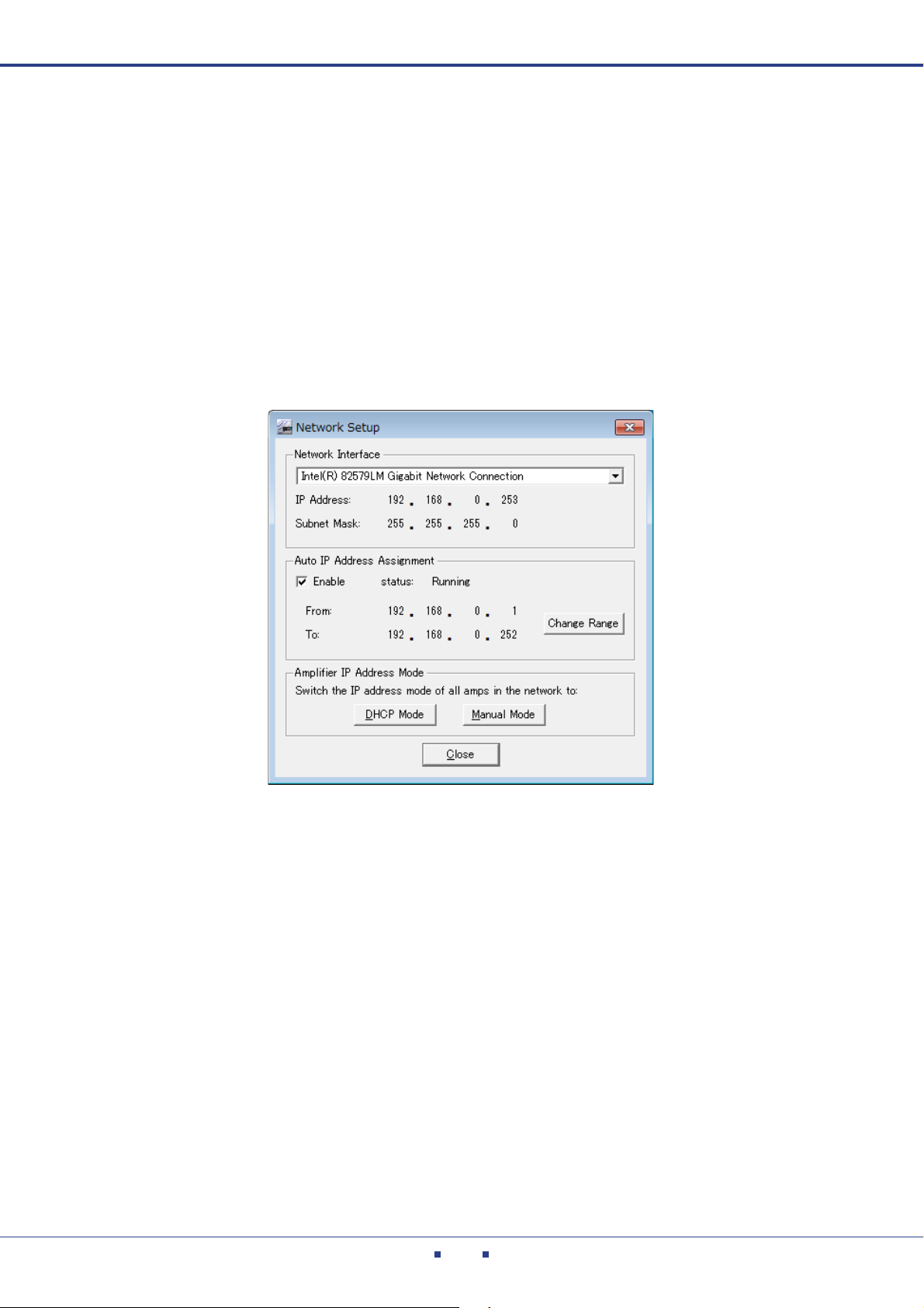
3. From the Amp Editor menu bar, choose [System] [Network Setup].
The “Network Setup” dialog box will appear.
4. In [Network Interface], select the network adapter you’re using.
As the network adapter, select the same card as you used in “Computer’s IP address setting.”
5. If necessary, click the [Change Range] button to edit the range of the IP address to be
assigned to the device.
6. If the [Enable] checkbox in the Auto IP Address Assignment section is not checked,
check it to enable the Auto IP Address Assignment function.
Amp Editor Owner’s Manual
20

Chapter 3 Setup
NOTE
7. Use an Ethernet cable to connect the [NETWORK] connector of the XMV to a network
switch, and then power-on all devices.
8. Verify that all connected devices are shown in the Tree View window.
• Make sure that all devices are displayed in the Tree View, then click the [Manual Mode] button.
In this way, the IP address assigned to the devices by the Auto IP Address Assignment function
will become static. This is a convenient way to assign a static IP address, especially if you want
to facilitate assignment of the IP address when the system starts up, or if you want to control
the devices using a remote controller, such as AMX/Crestron.
• Once the device IP address becomes static, uncheck the [Enable] checkbox in the Auto IP
Address Assignment section (page 92).
• It may take some time for IP addresses to be assigned to the devices. Correspondingly more
time will be required for a larger number of devices.
• If the network settings of a device are not the factory settings, it might not appear in the Tree
View window. In this case, operate the device’s front panel to change the IP Address Mode to
[DHCP], or initialize the device’s memory.
On the TXn unit, use [Utility] [Network Setup] to change the IP Address Mode to [DHCP],
and then press the unit’s front panel [ENTER] button.
On the ACD1 unit, use [6.Network Setup] [IP Address Mode] to change the IP Address
Mode to [DHCP]. For details on initializing the memory, refer to the owner’s manual or reference manual for each device.
Amp Editor Owner’s Manual
21

Chapter 3 Setup
Setting the device IP address (example for an XMV)
On the XMV, the IP address is automatically specified based on the unique UNIT ID of each device. The follow-
ing procedure is based on the assumption that these IP address settings are used for communication between the
devices and Amp Editor.
1. Before turning on the power to the devices, use an Ethernet cable to connect your com-
puter’s Ethernet connector to the network switch, and then start up the computer.
2. Click [Start] [All Programs] [Yamaha Amp Editor] [Amp Editor] to start Amp Edi-
tor.
3. From the Amp Editor menu bar, choose [System] [Network Setup].
The “Network Setup” dialog box will appear.
4. In [Network Interface], select the network adapter you’re using.
As the network adapter, select the same card as you used in “Computer’s IP address setting.”
5. If you are using the XMV4140-D, XMV4280-D, XMV8140-D, or XMV8280-D, and if the
[Enable] checkbox in the Auto IP Address Assignment section is checked, uncheck it to
disable the Auto IP Address Assignment function (page 92).
6. Make sure that the device setting DIP switch (IP SETTING) on the XMV’s rear panel is set
to UNIT ID.
7. Use an Ethernet cable to connect the [NETWORK] connector of the XMV to a network
switch, and then power-on all devices.
8. Verify that all connected devices are shown in the Tree View window.
Amp Editor Owner’s Manual
22
Chapter
NOTE
NOTE
NOTE
4
As examples of how amplifiers can be controlled from Amp Editor, this chapter explains the process of
editing the basic settings of each amplifier, creating a custom control panel from which you can monitor
and control multiple amplifiers, and then using Scene Link to switch multiple amplifiers together.
• Before you continue with the procedure described below, you must make IP address and Device ID settings for
• For details on how to connect the ACD1 to an amplifier and set the AMP ID, refer to the ACD1 Owner’s Manual.
Basic operations in Amp Editor
your computer and devices as described in “Setup” (page 15).
Synchronizing Amp Editor and the devices
Here’s how to perform synchronization so that the devices can be monitored and controlled from Amp Editor.
1. After you’ve powered-on your equipment, start up Amp Editor.
The main panel window and the Tree View window will appear.
The connected devices are shown in the workspace of the Tree View window.
• If a connected device is not shown in the workspace, refer to “Troubleshooting” (page 210).
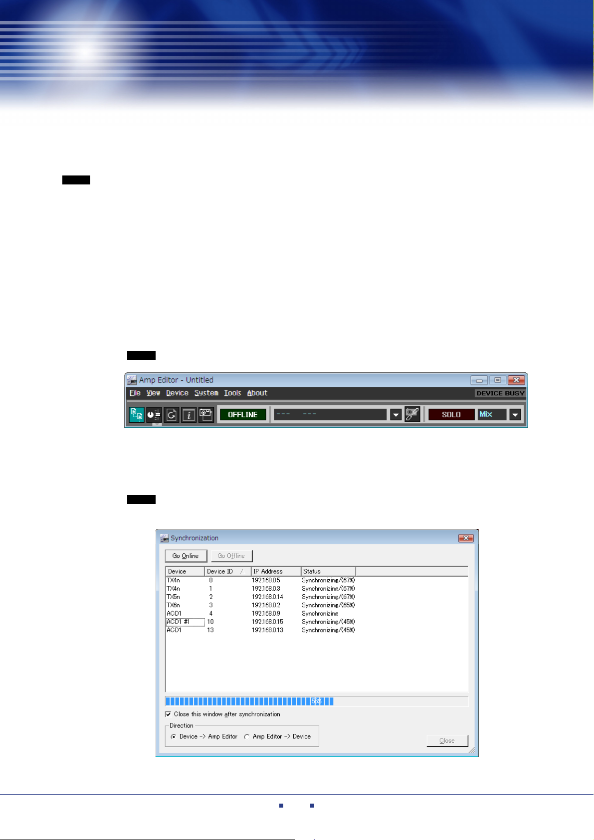
2. In the main panel window, click the [OFFLINE] button.
The “Synchronization” screen (page 94) will appear. Verify that the connected TXn(s) and/or ACD1(s)
are shown.
• Amplifiers connected to the ACD1 are not shown. To verify that the amplifiers are connected to
the ACD1, follow the steps below:
Amp Editor Owner’s Manual
23
Chapter 4 Basic operations in Amp Editor
NOTE
NOTE
3. Use the Direction field to specify the direction of synchronization, and then click the [Go
Online] button.
Amp Editor and the devices will synchronize, and the indication in the main panel window will change to
[ONLINE].
• If you choose [Amp Editor Device], synchronization will occur by sending data from Amp Editor to the devices. In this case, please take care that unexpected high volume does not damage
your speakers or cause hearing damage.
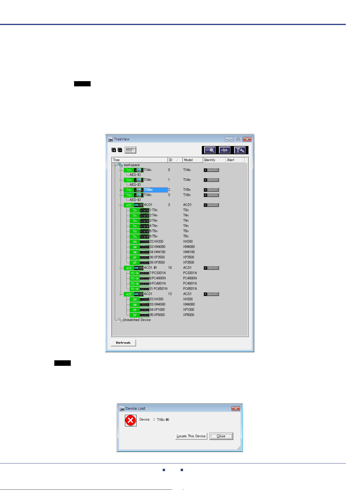
When you switch to [ONLINE], the amplifier icons shown in the workspace of the Tree View window
will turn green.
• If synchronization with the devices is not possible due to a network problem, information about the
devices that were unable to synchronize will be displayed. Check the network cable connections, and
try again from step 2 of the procedure.
• If the Amp Editor does not recognize the synchronized devices, a dialog box which indicates the devices
that were unable to be recognized will appear.
Amp Editor Owner’s Manual
24
Chapter 4 Basic operations in Amp Editor
[Device Properties] button
q
w
e
Making basic settings for each amplifier
Here you’ll make basic settings such as the amplifier’s Gain and Power Amp Mode.
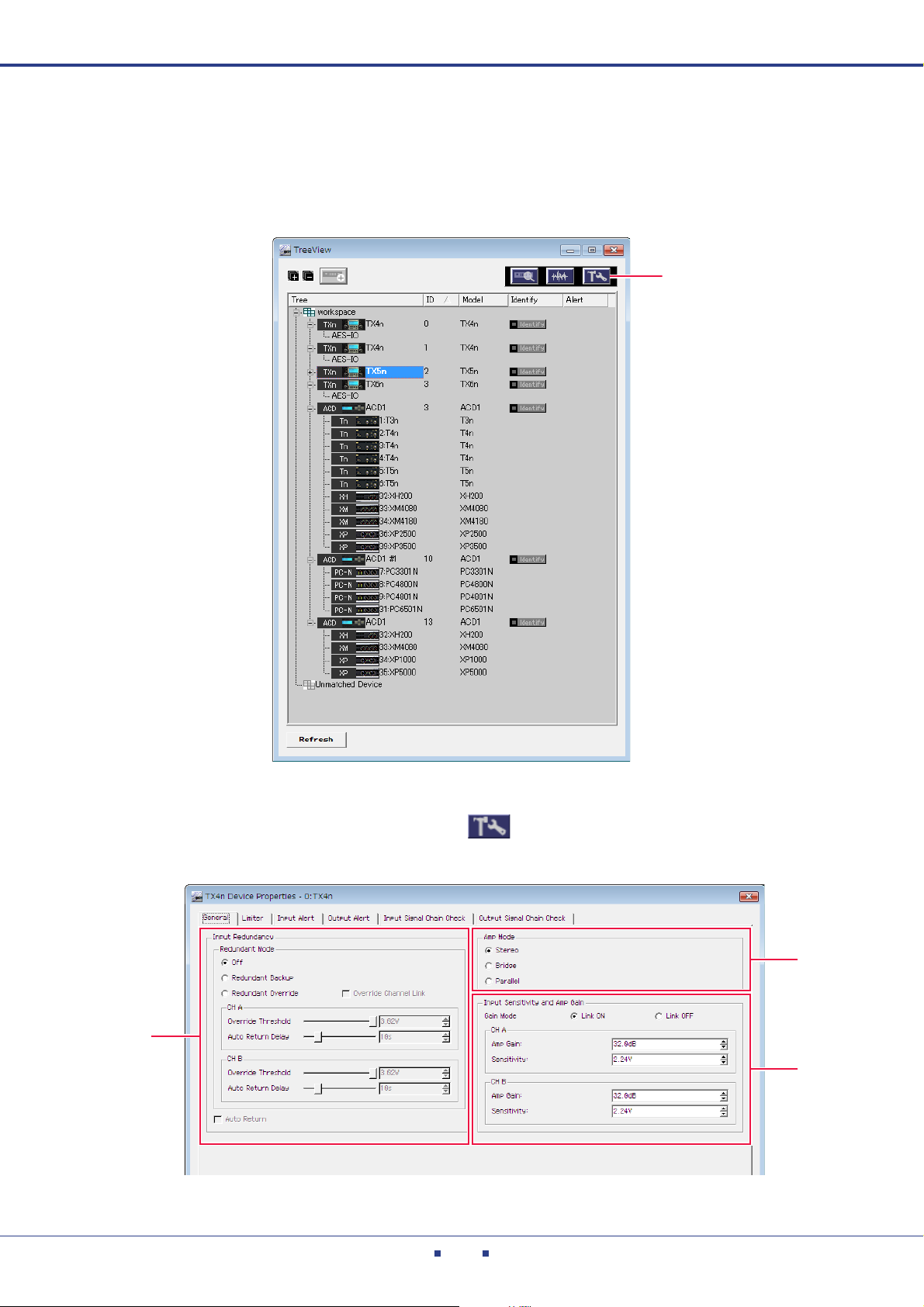
4. Click an amplifier icon in the workspace of the Tree View window.
5. Click the [Device Properties] button ( ).
The Device Properties window will appear.
Amp Editor Owner’s Manual
25
Chapter 4 Basic operations in Amp Editor
NOTE
6. Make basic settings for the amplifier.
In the “General” tab you can make the following basic settings. For details, refer to Device Properties
window (page 127).
q Input Redundancy
Here you can make settings for a redundant connection (duplicate audio connections) that uses both
the analog input signal and the digital (slot) input signal. If the digital input audio is interrupted by a
broken connection or other problem, the amplifier can automatically switch to the analog input
(Redundant Backup), or the amplifier can automatically switch to the analog input simply when an
analog audio input signal is detected (Redundant Override).
By default, this is Off.
w Amp Mode
This specifies the amplifier’s output mode (Stereo/Bridge/Parallel).
The default setting is [Stereo].
e Input Sensitivity and Amp Gain
This specifies the gain (Amp Gain) and input sensitivity (Sensitivity) for each channel. Gain and
input sensitivity settings are linked.
The default settings are “Amp Gain” [32.0 dB], “Sensitivity” [11.8 dBu] (for the Tx6n) / [10.4 dBu]
(for the Tx5n) / [9.2 dBu] (for the Tx4n).
•Gain Mode
This specifies whether the gain / input sensitivity settings will be linked between
channels A/B when the Amp Mode is Stereo.
The default setting is Link On.
7. Click the [Close] button to close the dialog box.
8. Repeat steps 4 through 7 to make basic settings for the other amplifiers.
• You can copy basic settings as described in “Copying settings” (page 106).
Amp Editor Owner’s Manual
26
Chapter 4 Basic operations in Amp Editor
NOTE
NOTE
Monitoring and controlling multiple amplifiers
By using the “System View Creator” dialog box you can create a System View custom control panel that enables
centralized monitoring and control of multiple amplifiers.
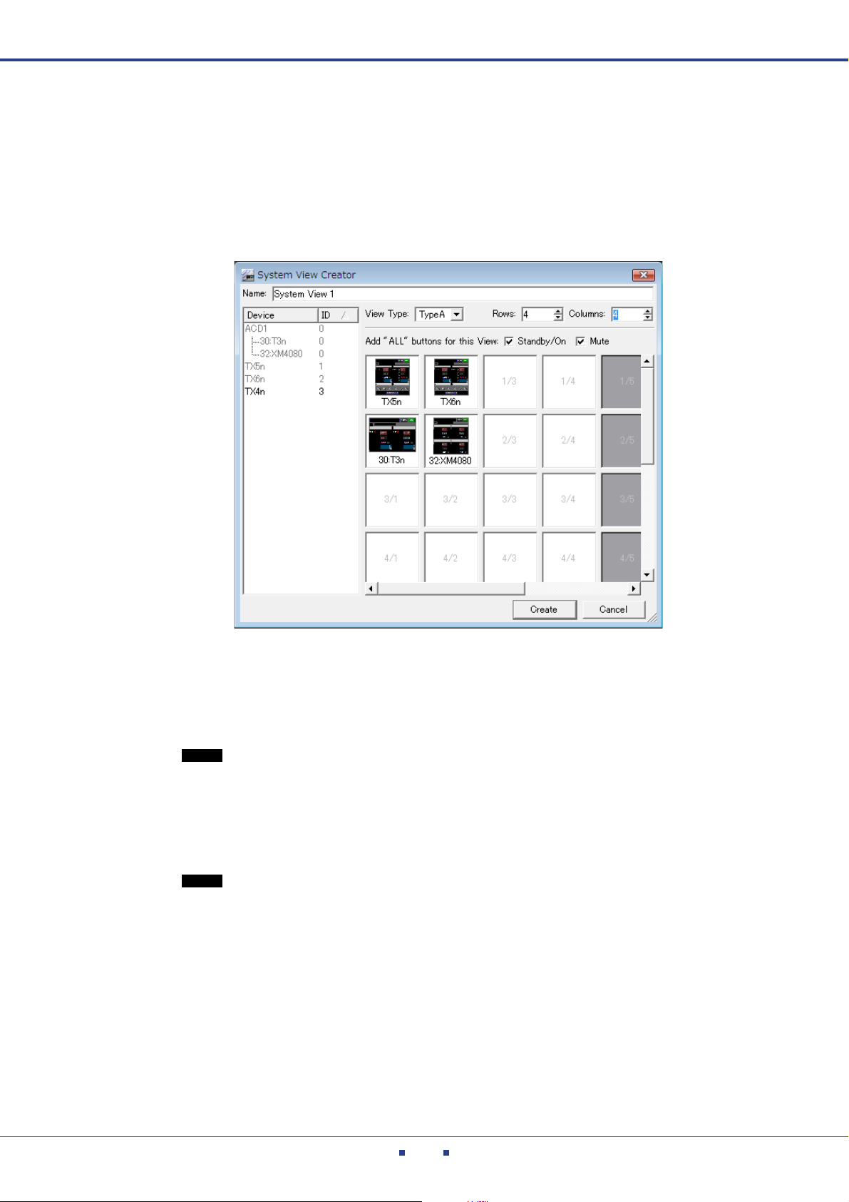
9. From the [Tools] menu, choose [System View Creator...].
The “System View Creator” dialog box will appear.
10.
In the [Name] field, enter the name of the custom control panel that you want to create.
11.
In this example, select [Type A] for the [Type] field.
[Type A] displays more controllers than [Type B].
• If you select [Type B], you’ll be able to monitor and control a larger number of amplifiers in a single screen, but there will be fewer controllers.
12.
From the Device list, drag an amplifier that you want to monitor and control, and drop it
into the desired cell.
The amplifier will be placed at that location. Place the other amplifiers in the same way.
• By default, the cell layout will be 4 x 4. Use [Rows] and [Columns] to edit the layout if desired.
• If the [Standby/On] check box or the [Mute] check box is selected, a button will be added, allowing you to switch the power status or muting of all amplifiers registered in the custom control
panel.
13.
When you’ve finished placing the amplifiers, click the [Create] button.
The “System View Creator” dialog box will close, and the System View custom control panel you created
will open. You can use this custom control panel to monitor and control multiple amplifiers.
Amp Editor Owner’s Manual
27
Chapter 4 Basic operations in Amp Editor
q
e
y
u
r
w
t
i
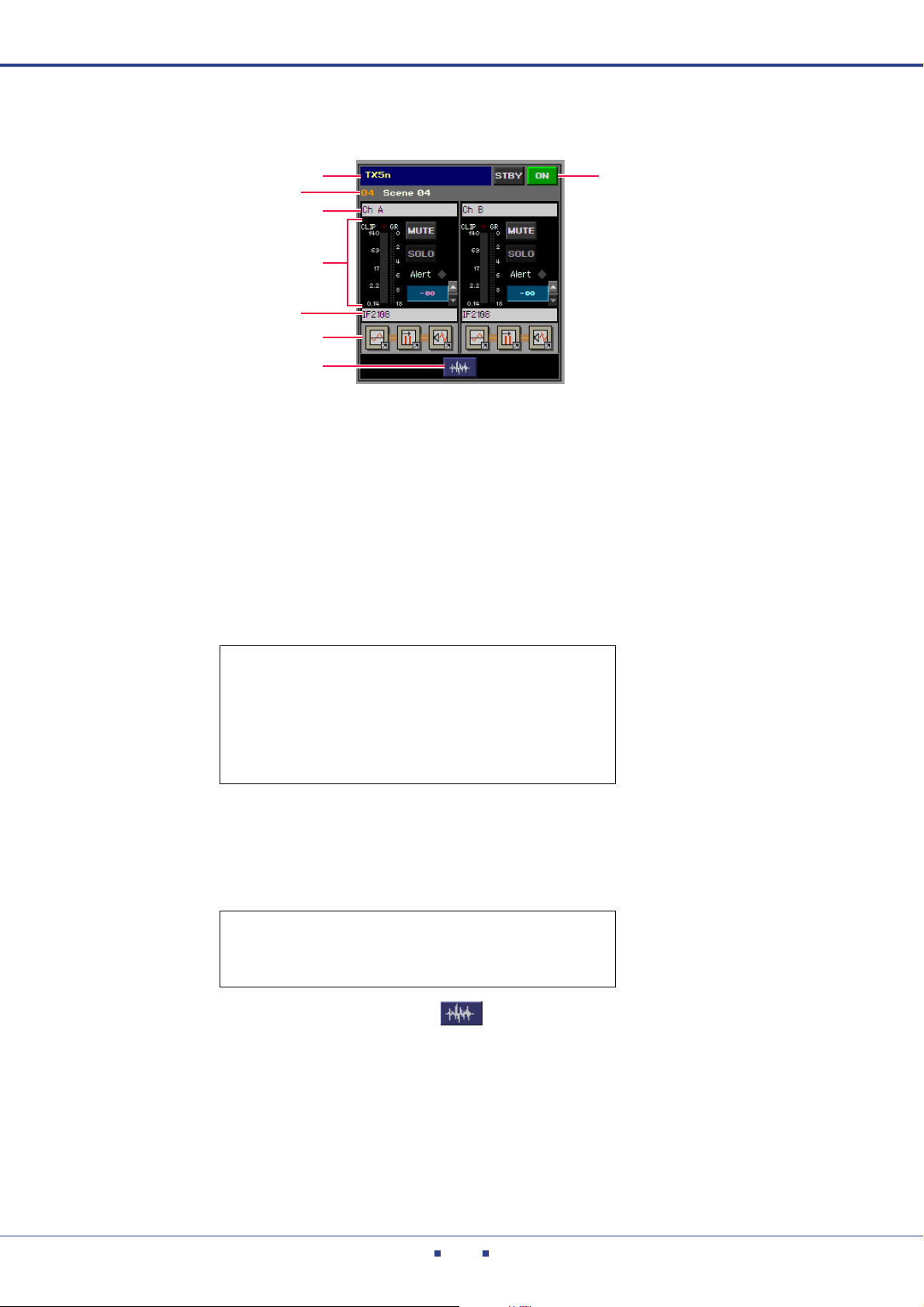
Type of TXn has the following structure.
q Amplifier name
Indicates the name of the amplifier.
w Scene name
Indicates the amplifier’s scene number and scene name.
e Channel name
Indicates the amplifier’s channel name.
r Amplifier control section
Here you can monitor and control the following items.
• Level meter / GR meter indication
•MUTE on/off
• SOLO on/off
• Alert indication (This will light if any alert indicator in the
Device Detail View is lit.)
• Attenuator operation
t Library name
Indicates the amplifier’s Speaker Processor library name.
y [EQ] icon / [Delay] icon / [SP] icon
You can click these to access the following component editors.
• 8 Band EQ
• Input Delay
• Speaker Processor
u [Signal Path View] button ( )
This opens the Signal Path View window. In the Signal Path View window you can access all compo-
nent editors.
i [STBY]/[ON] button
Monitors and controls the status (Standby/On) of the amplifier’s power supply.
Amp Editor Owner’s Manual
28
Chapter 4 Basic operations in Amp Editor
NOTE
Editing an amplifier’s Speaker Processor component settings
(TXn only)
For each channel of the amplifier, you can edit the settings (the parameter set) of the Speaker Processor compo-
nent for the speaker you’re using.
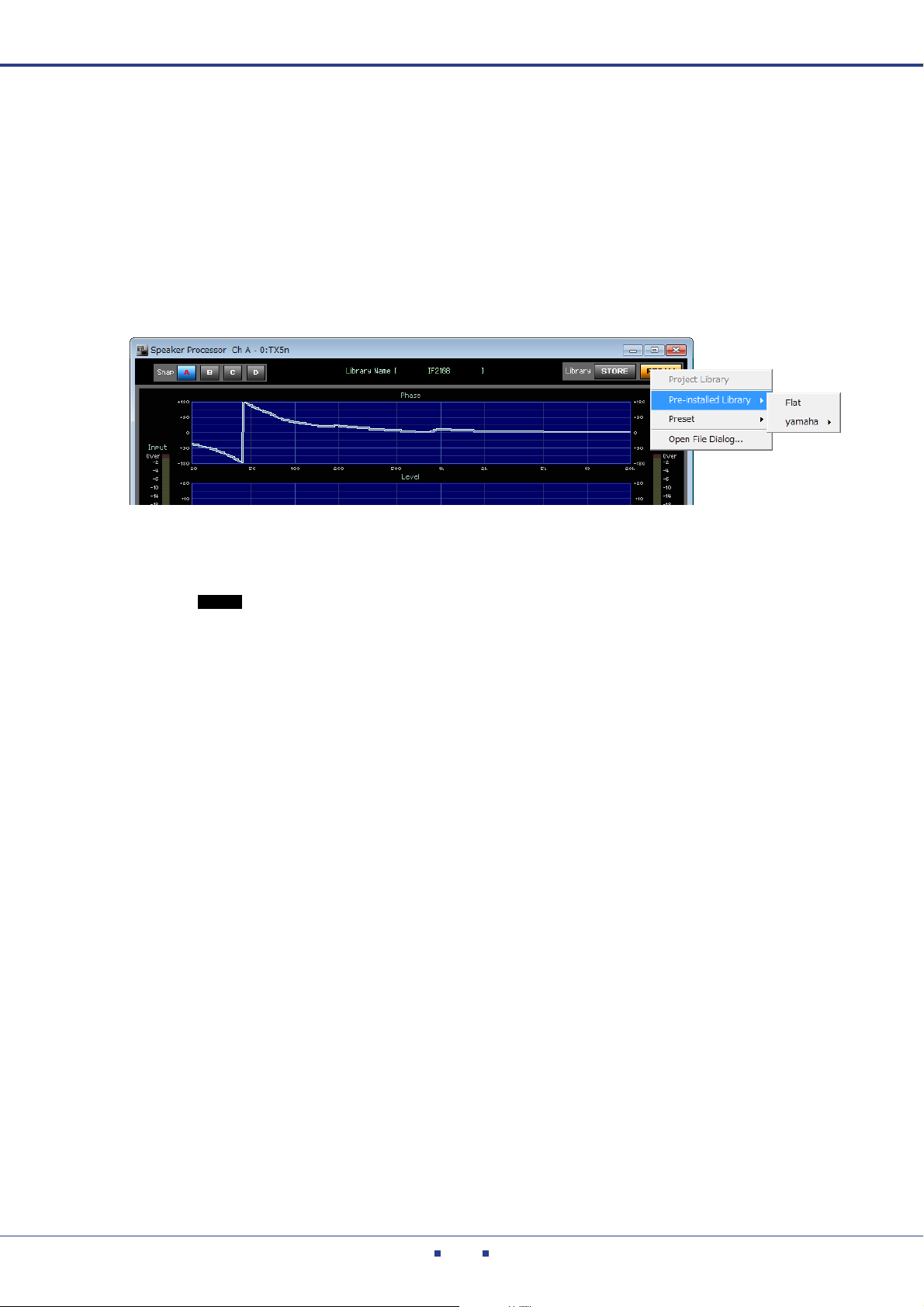
14.
Click the [SP] icon of the channel whose Speaker Processor component settings you
want to edit.
The “Speaker Processor” dialog box will open.
15.
Click the [RECALL] button to select the library item for the speaker you’re using.
The parameter set for the Speaker Processor component will be switched.
• If you want to use a library file created in DME Designer (file name extension “.cel”), use the
“Speaker Processor Library Converter” (page 101) to convert it to a library item file for TXn.
• If the library is created with an extension, the file name extension “.ce2” indicates “without security” and “.cep” means “with security.”
16.
Click the [X] button located in the upper right of the dialog box to close it.
17.
Repeat steps 14 through 16 to change the Speaker Processor component library item for
each channel of each amp.
Amp Editor Owner’s Manual
29
Chapter 4 Basic operations in Amp Editor
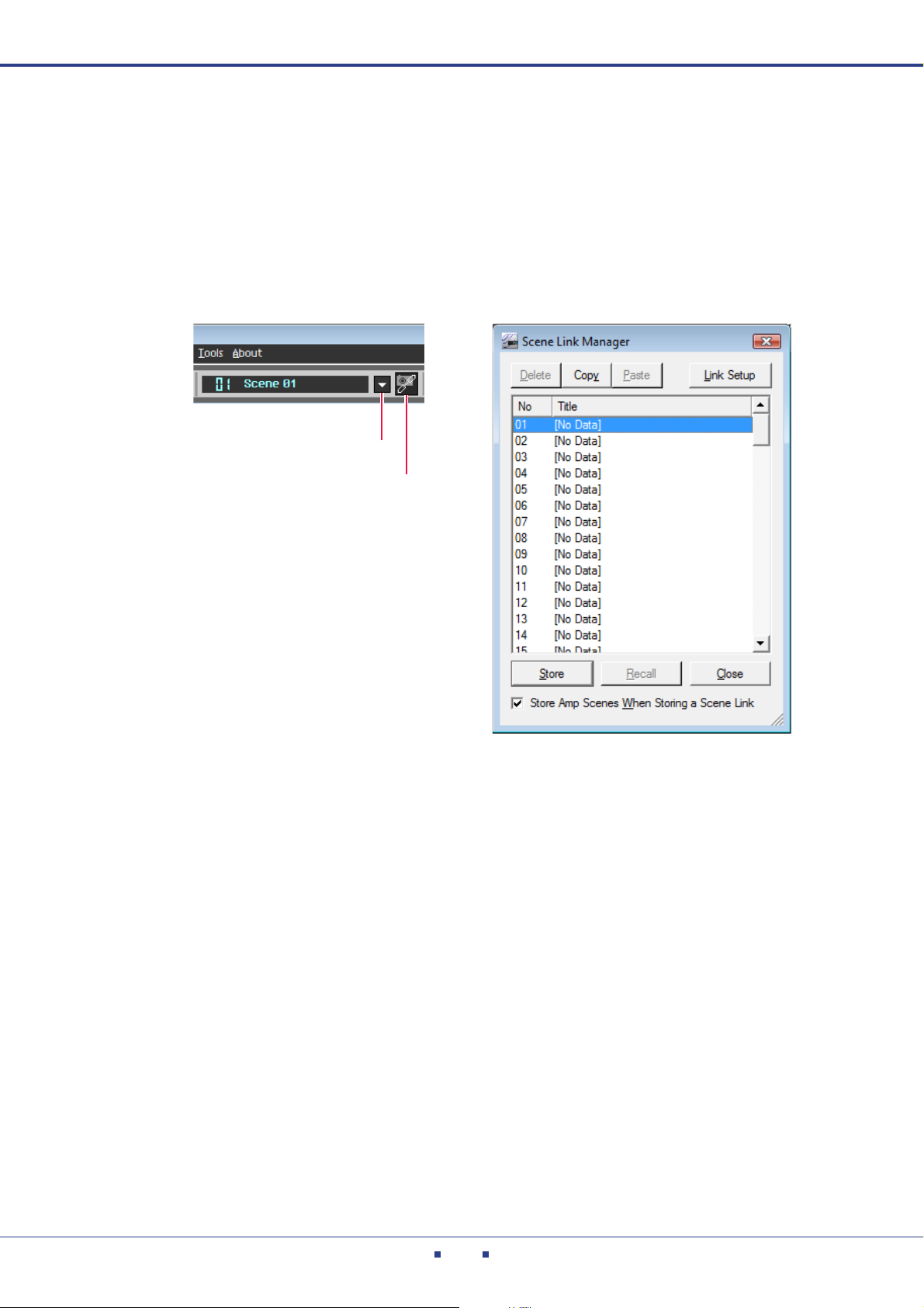
[Change Scene Link] button
[Scene Link Manager] button
Using Scene Link to switch the settings of multiple amplifiers simul-
taneously
If you use Scene Link to associate the scenes of multiple amplifiers, the scenes of multiple amplifiers can be
stored/recalled simultaneously.
18.
In the main panel window, click the [Scene Link Manager] button.
The “Scene Link Manager” dialog box will open.
19.
In the Scene Link list, click [01 [No Data]] to select it.
If 01 is not [No Data], select any scene link that indicates [No Data].
20.
Select the [Store Amp Scenes When Storing a Scene Link] check box.
When you store the scene link, the scene of the corresponding amplifiers will also be stored.
Amp Editor Owner’s Manual
30
 Loading...