


YAMAHA
MIXER
TABLE DE MIXAGE
MISCHPULT
AÎVl
OPERATION MANUAL
MANUEL D'INSTRUCTIONS
BEDIENUNGSANLEITUNG
(F
YAMAHAM,xB.AIVlBOi
3 POWER
3 CLIP
a SIGNAL
MASTER U PHONES
3 CLIP
a SIGNAL
J
• Explanation of Graphical Symbols
CAUTION
RISK OF ELECTRIC SHOCK
DO NOT OPEN
CAUTION: TO REDUCE THE RISK OF
ELECTRIC SHOCK, DO NOT REMOVE
COVER (OR BACK). NO USER-SERVICEABLE
PARTS INSIDE. REFER SERVICING TO
QUALIFIED SERVICE PERSONNEL
SAFETY INSTRUCTIONS
1. Read Instructions—All the safety and operating instructions
should be read before the appliance is operated.
2. Retain Instructions—The safety and operating instructions
should be retained for future reference.
3. Heed Warnings—All warnings on the appliance and in the
operating instructions should be adhered to.
4. Follow Instructions—All operating and use instructions should
be followed.
5. Water and Moisture—The appliance should not be used near
water—for example, near a bathtub, washbowl, kitchen sink,
laundry tub, in a wet basement, or near a swimming pool,
and the like.
6. Carts and Stands—The appliance
should be used only with a cart or
stand that is recommended by the
manufacturer.
6A. An appliance and cart combination
should be moved with care. Quick
stops, excessive force, and uneven
surfaces may cause the appliance
and cart combination to overturn.
7. Wall or Ceiling Mounting—The appliance should be mounted
to a wall or ceiling only as recommended by the manufac
turer.
8. Ventilation—The appliance should be situated so that its
location or position does not interfere with its proper venti
lation. For example, the appliance should not be situated on
a bed, sofa, rug, or similar surface that may block the ven
tilation openings: or placed in a built-in installation, such
as a bookcase or cabinet that may impede the flow of air
through the ventilation openings.
9. Heat—The appliance should be situated away from,heat
sources such as radiators, heat registers, stoves, or other
appliances (including amplifiers) that produce heat.
The lightning flash with arrowhead symbol within an
equilateral triangle is intended to alert the user of the
presence of uninsulated “dangerous voltage” within the
A
product’s enclosure that may be of sufficient magnitude
to constitute a risk of electric shock to persons.
The exclamation point within an equilateral triangle is
intended to alert the user to the presence of important
operating and maintenance (servicing) instructions in the
literature accompanying the product.
10. Power Sources—The appliance should be connected to a
power supply only of the type described in the operating
instructions or as marked on the appliance.
11. Grounding or Polarization—^The precautions that should be
taken so that the grounding or polarization means of an
appliance is not defeated.
12. Power-Cord Protection—Power-supply cords should be routed
so that they are not likely to be walked on or pinched by
items placed upon or against them, paying particular atten
tion to cords at plugs, convenience receptacles, and the point
where they exit from the appliance.
13. Cleaning—The appliance should be cleaned only as recom
mended by the manufacturer.
14. Nonuse Periods—The power Cord of the appliance should
be unplugged from the outlet when left unused for a long
period of time.
15. Object and Liquid Entry—Care should be taken so that objects
do not fall and liquids are not spilled into the enclosure
through openings.
16. Damage Requiring Service—The appliance should be serv
iced by qualified service personnel when:
A. The power-supply cord or the plug has been damaged;
or
B.
Objects have fallen, or liquid has been spilled into the
appliance; or
The appliance has been exposed to rain; or
C.
D.
The appliance does not appear to operate normally or
exhibits a marked change in performance; or
E.
The appliance has been dropped, or the enclosure damaged.
17. Servicing—The user, should not attempt to service the ap
pliance beyond that described in the operating instructions.
All other servicing should be referred to qualified service
personnel.

Your AM602 is a high-performance 6-inl2-out mixer that will deliver outstanding sonic performance
and broad control versatility in a variety of applications.
In order to make the most of the AM602's many features and fine performance, we urge you to read
this operation manual thoroughly, and keep it in a safe place for later reference.
CONTENTS
Congratulations!
CONTROLS & CONNECTORS
CONTROLS .................................................... 3
Input Channels
Master Control Section
CONNECTORS
...........................................
.............................................
...............................
.............................
2
3
4
PRECAUTIONS
1. AVOID EXCESSIVE HEAT, HUMIDITY,
DUST AND VIBRATION
Keep the unit away from locations where it is likely
to be exposed to high temperatures or humidity —
such as near radiators, stoves, etc. Also avoid lo
cations which are subject to excessive dust accu
mulation or vibration which could cause mechanical
damage.
2. AVOID PHYSICAL SHOCKS
Strong physical shocks to the unit can cause dam
age. Handle it with care.
3. DO NOT OPEN THE CASE OR ATTEMPT
REPAIRS OR MODIFICATIONS YOURSELF
This product contains no user-serviceable parts.
Refer all maintenance to qualified YAMAHA service
personnel. Opening the case and/or tampering with
the internal circuitry will void the warranty.
SAMPLE APPLICATIONS
BLOCK DIAGRAM
DIMENSIONS ...........................................................7
4
SPECIFICATIONS
LEVEL DIAGRAM...................................................35
..................................................
...................................................
......................................
6
7
8
5. HANDLE CABLES CAREFULLY
Always plug and unplug cables — including the AC
cord — by gripping the connector, not the cord.
6. CLEAN WITH A SOFT DRY CLOTH
Never use solvents such as benzine or thinner to
clean the unit. Wipe clean with a soft, dry cloth.
7. ALWAYS USE THE CORRECT POWER
SUPPLY
Make sure that the power supply voltage specified
on the rear panel matches your local AC mains
supply.
4. MAKE SURE POWER IS OFF BEFORE
MAKING OR REMOVING CONNECTIONS
Always turn the power OFF prior to connecting or
disconnecting cables. This is important to prevent
damage to the unit itself as well as other connected
equipment.
1 -
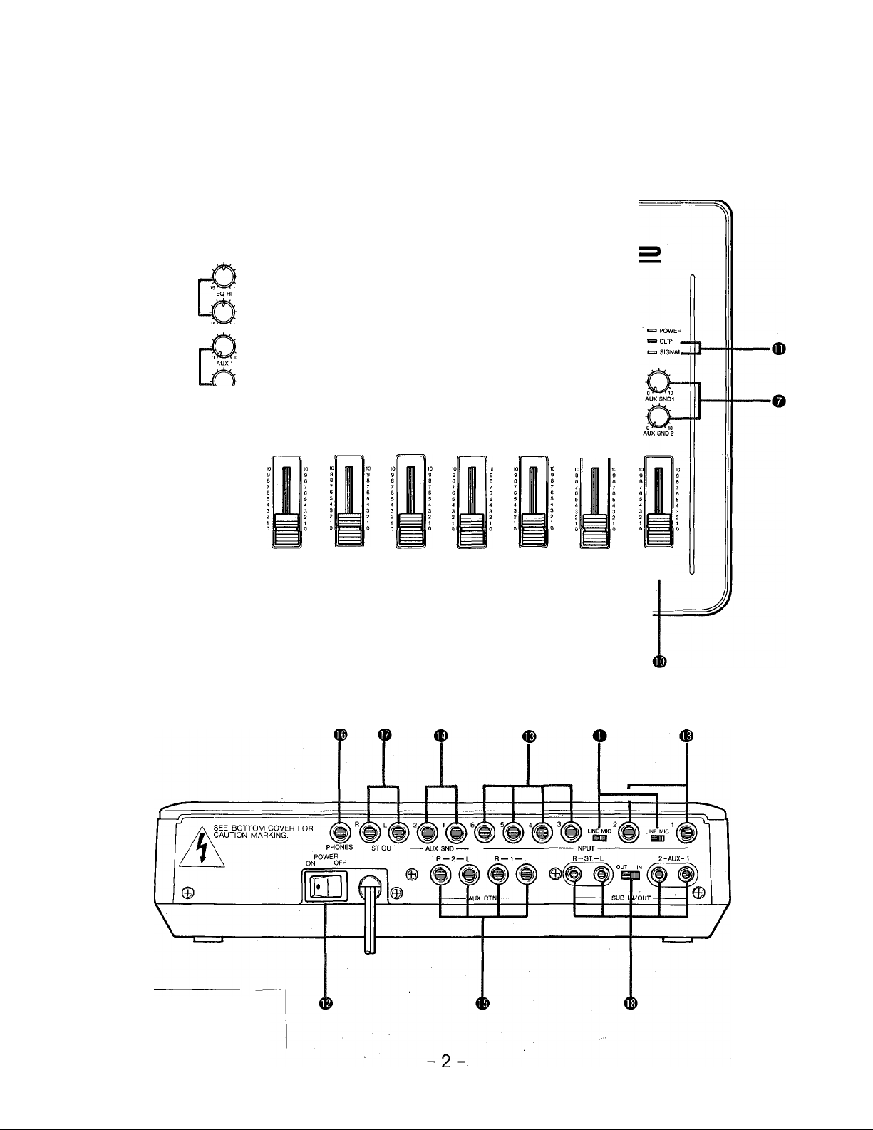
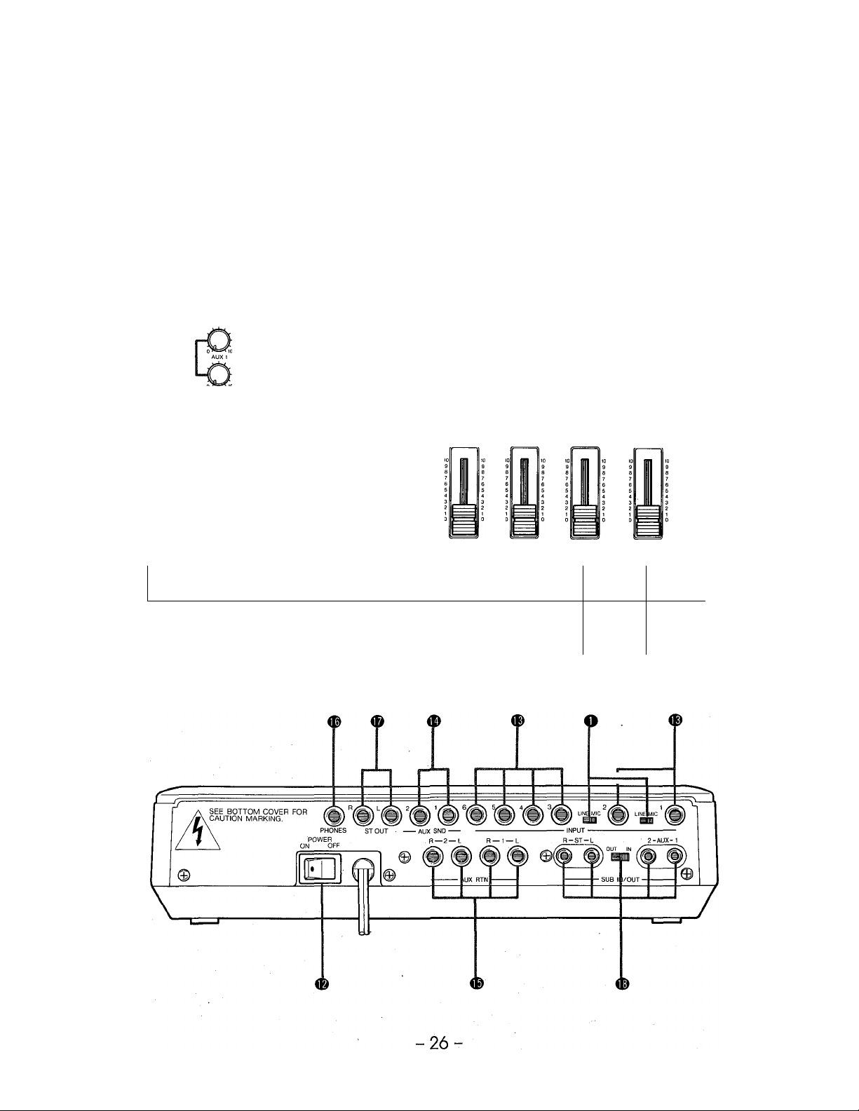
CONTROLS & CONNECTORS
CONTROL PANEL
YAMAHAmixebADVI
&-
©-
» CUP
1 SIGNAL
©L
REAR PANEL
6 U MASTER U PHONES
i
CAUTION: TO PREVENT ELECTRIC
SHOCK, MATCH WIDE BLADE OF PLUG
TO WIDE SLOT, FULLY INSERT.
CONTROLS
• Input Channels
o MIC/LINE Switch (Rear Panel)
— Channels 1 & 2
This switch sets the input sensitivity of the corre
sponding input to match line-level or microphone-level
input sources. If you will be connecting a line-level
source such as an electronic keyboard or audio
equipment, set the switch to LINE. If you will be con
necting a microphone or other low-level source, set
the switch to MIC.
O GAIN Control — Channels 1 & 2
This control adjusts the input sensitivity of the corre
sponding input channel. Continuously variable gain
control allows optimum matching with virtually any
microphone or line source.
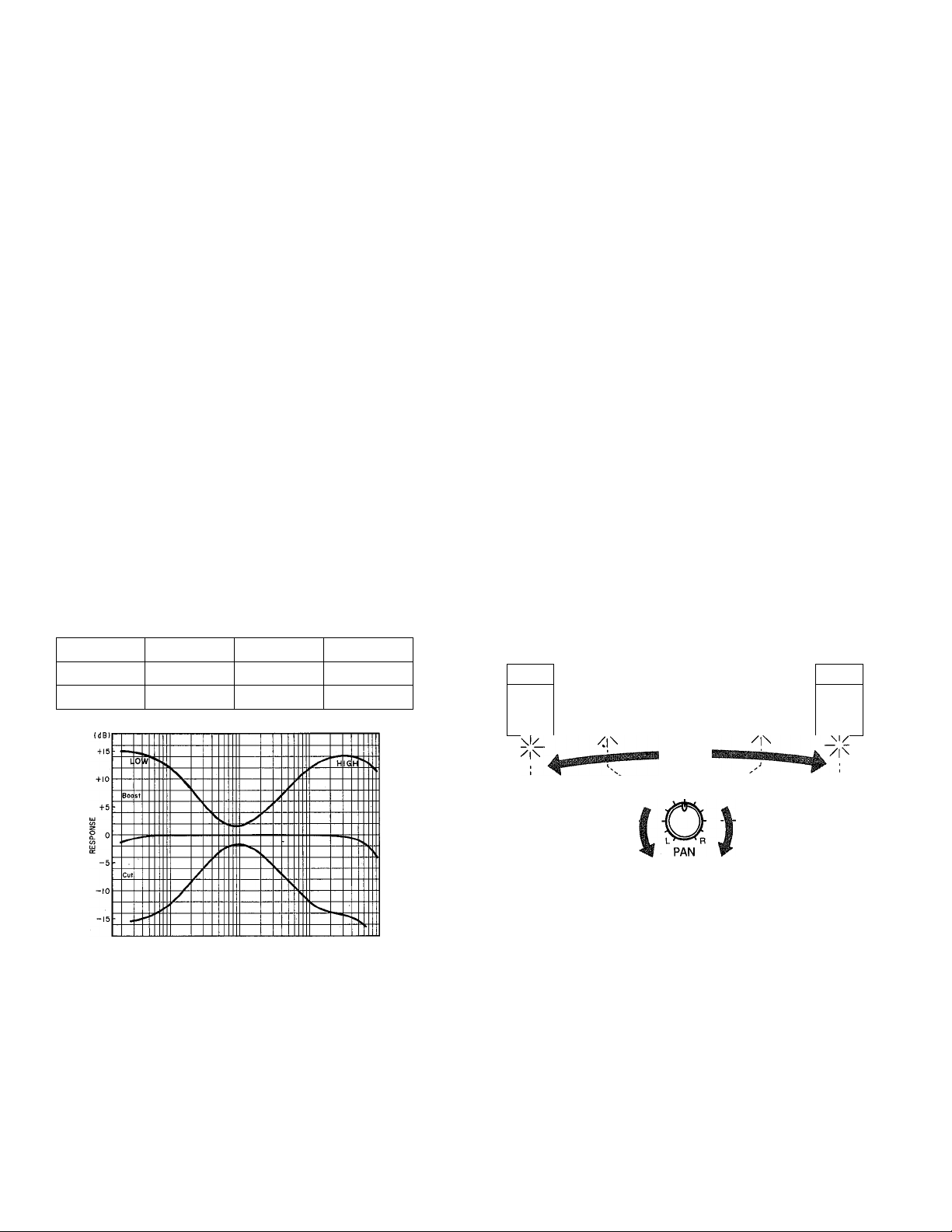
0 EQ LO & HI Controls — Channels 1 & 2
These controls permit individually modifying the re
sponse of each channei. The HI and LO EQ controls
function as follows:
Control
HI
LO
Range Freq.
+15 dB
±15 dB 100 Hz
10 kHz
Type
Shelving
Shelving
controls can be used to produce two independent
mixes to feed external effect devices, a performer’s
headphone cue system or other system fed by the
AUX SND jacks. All AUX controls are “post-EQ/postfader,” meaning that their signal is derived from a
point after the channel EQ stage and fader. This
means that the AUX signal is affected by the channel
EQ and fader settings.
0
PAN Control
The PAN controls assign the signal from the corre
sponding channel to any desired position in the "ste
reo sound field.” If a PAN control is set to the maxi
mum “L” (LEFT) position, the signal from that channel
will appear only at the left-channel output (ST QUT L).
If the PAN control is set fully “R” (RIGHT), the signal
will appear only at the ST QUT R output jack. If a
PAN control is set to its center position, then the sig
nal from that channel will appear equally at both the
left- and right-channel outputs, and the sound will
appear at the center of the stereo sound field (at a
point midway between the two stereo speakers).
Qther PAN control settings place the sound at posi
tions roughly corresponding to the PAN control setting
by varying the level of the signal sent to the left- and
right-channel outputs.
LEFT
SPEAKER
\l/
\l/
/|\
RIGHT
SPEAKER
\l/
rxi
Ik
FREQUENCY
o AUX Controls
The AUX 1 and AUX 2 controls on the AM602 deter
mine the level of the signal sent from that channel to
the AUX 1 and AUX 2 mixing busses, respectively.
The AUX mixing busses then feed the corresponding
AUX SND level controls and finally the corresponding
rear-panel AUX SND output jacks. The channel AUX
0
Channel Fader
This is the main level control for each input channel. It
determines the level of the signal sent from the corre
sponding input channel to the master stereo buss.
The settings of the input channel faders determines
the “mix” or balance of sound levels between the in
struments or other sources connected to the inputs.
NOTE:
If a channel is not being used, its fader should be
set to the minimum position to prevent unwanted
noise from being added to the main program sig
nals.
---------------
------------------------------------

• Master Control Section
O AUX SND Controls
These adjust the overall output level of the AUX 1 and
AUX 2 “mixes” set up using the corresponding chan-
nei AUX controis. AUX SND 1 sets the overail level of
the AUX 1 mix signal ap|3earing at the AUX SND 1
jack, and AUX SND 2 sets the overall level of the
AUX 2 mix signal appearing at the AUX SND 2 jack.
These controls should be used to optimally match the
AUX SND output level of the mixer to the input sensi
tivity of the external signal processing device or power
amplifier used.
© AUX RTN Controls
These controls adjust the level of the signal received
at the corresponding rear-panel AUX RTN jacks and
mixed into the main program on the master stereo
buss. Stereo inputs are provided for each AUX RTN
input, providing compatibility with the many mono-in/
stereo-out signal processors currently available.
© MASTER Fader
The MASTER fader controls the master output levels
of both the left and right channels, and thus the level
of the signals appearing at the ST OUT L and R jacks.
© PHONES Control
Adjusts the level of the master stereo program signal
applied to the rear-panel PHONES jack. Use the
PHONES control to set the most comfortable head
phone monitoring level.
© Level Indicators
The AM602 has left- and right-channel SIGNAL and
CLIP LEDs. The SIGNAL LEDs light when a signal of
sufficiently high level is detected in the corresponding
channel, and the CLIP LEDs will light if the signal in
the corresponding channel reaches a level 3-dB be
low clipping. If the either of the CLIP indicators lights
more than just occasionally on high-level peaks, the
fader levels or levels of the sources connected to the
mixer’s inputs should be reduced to prevent possible
overload distortion.
© POWER Switch (Rear panel)
Flip to the ON position to turn power ON, or to the
OFF position to turn power OFF. The POWER indica
tor LED will light when the power switch is turned ON.
- CAUTION: ---------------------------------------------
Make sure the MASTER fader is set to minimum
when turning the POWER switch ON. '
-
CONNECTORS
© INPUT Connectors
The AM602 has a total of 6 input channels, each of
which has a single 1/4" monaural phone INPUT jack.
See “O MIC/LINE Switch” for a description of the
MIC/LINE switches associated with INPUT jacks 1
and 2. When a MIC/LINE switch is set to MIC, the
input level and impedance for that channel are set to
-50 dB/50—600 ohms. When set to LINE, the input
level and impedance are -10 dB/600 ohms. The input
level and impedance for INPUTS without MIC/LINE
switches are -10 dB/600 ohms.
© AUX SND Jacks
These jacks deliver the AUX 1 and AUX 2 mixes,
respectively, to feed an external signal processor, a
monitor system, etc. Nominal output level and imped
ance of the AUX SND jacks are -10 dB/10 kohms.
© AUX RTN Jacks
The output from signal processors fed by the AUX'
SND jacks can be returned to the master stereo buss
via these jacks. Stereo AUX RTN jacks offer compati
bility with the wide range of mono-in/stereo-out signal
processors currently available. The AUX RTN jacks
can also be used to add external signals other than
the output from signal processor to the stereo buss.
Nominal input level and impedance are -20 dB/600
ohms.
© PHONES Jack
The PHONES jack delivers the mixer’s master stereo
program signal to a pair of standard 8 ohm stereo
headphones. The PHONES control adjusts the head
phone monitoring level.
© ST OUT L & R Jacks
The main outputs from the mixer’s stereo buss. These
1/4" monaural phone jacks deliver the stereo buss
signal at 0 dB/10 kohms (nominal).
-4-
CONTROLS & CONNECTORS
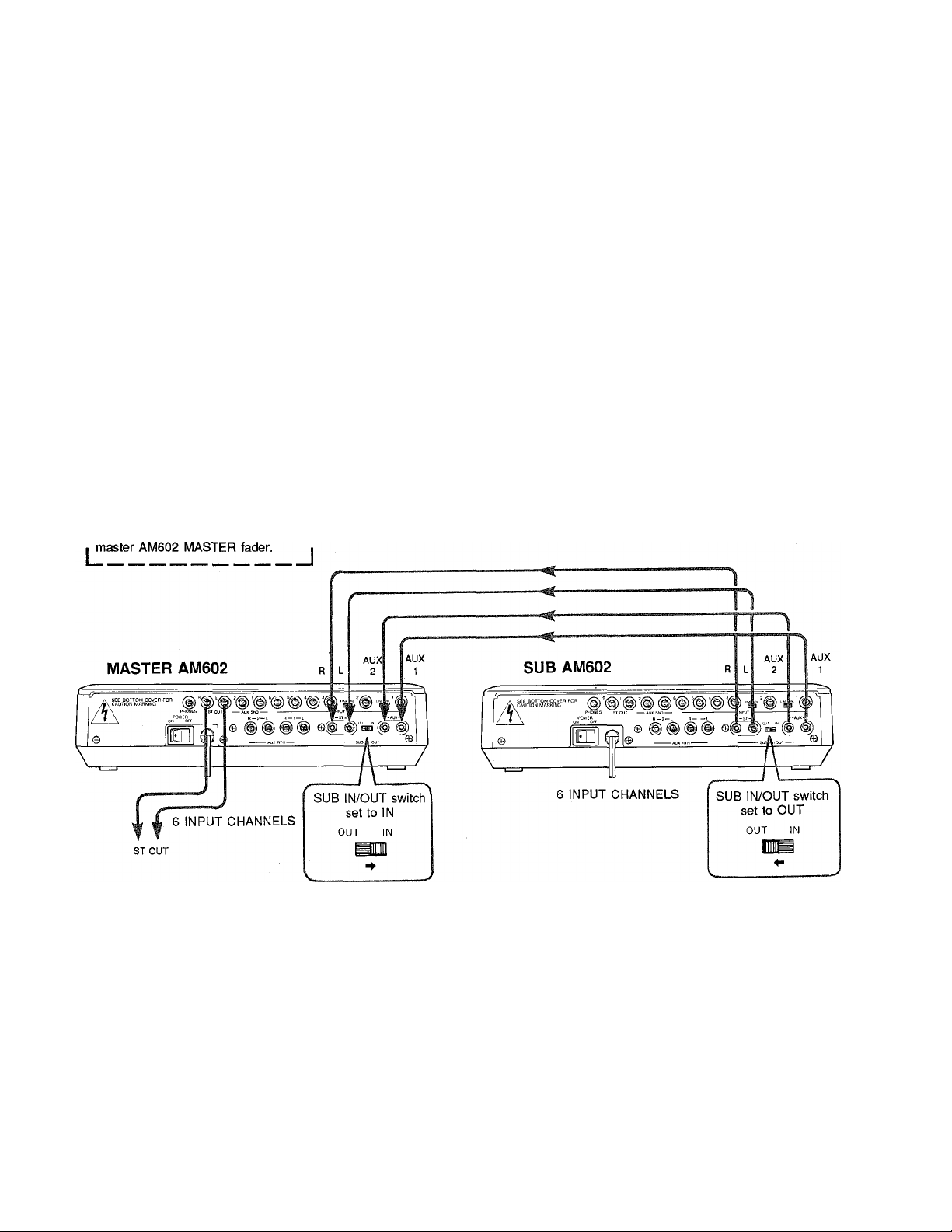
® SUB IN/OUT Jacks
These four jacks and selector switch permit “cascad
ing” two AM602 units to increase the number of avail
able input channels to 12. When two AM602 units are
cascaded, one functions as a “sub-mixer” and the
second as a “master mixer.” The input channels on
the sub-mixer operate normally but the master section
controls are not used. The input channels of the mas
ter mixer also function normally, and its master sec
tion controls the entire system. That is, the MASTER
fader, AUX SND and AUX RTN controls of the master
mixer function for all 12 input channels. The SUB IN/
OUT switch determines whether the SUB IN/OUT
jacks function as inputs or outputs, and thus whether
the AM602 functions as sub-mixer or master mixer.
For sub-mixer operation the SUB IN/OUT switch
Fu
Use master AM602 AUX SND and
I AUX RTN controls and jacks. Use |
71
should be set to the “OUT” position, while for master
mixer operation it should be set to the “IN” position.
The diagram below shows the proper connections
and switch settings.
r NOTE:
For normal single-mixer operation the SUB IN/OUT
switch should be set to the “IN” position. In this
condition the SUB IN/OUT L, R , AUX 1 and AUX 2
jacks function as inputs, and can be used to feed
external line-level signals into the mixer’s stereo
master buss and AUX busses. If the SUB IN/OUT
switch is set to the OUT position, however, the
SUB IN/OUT L and R jacks can be used as “REC
OUT” jacks, providing a line-level signal for record
ing, etc.
----------------------------------------------------
IMPORTANT NOTES
MAKE SURE THE MIXER’S POWER SWITCH IS OFF OR THE MASTER FADER IS SET TO MINIMUM WHEN
CONNECTING OR DISCONNECTING ANY CABLES.
ALWAYS TURN THE MIXER’S POWER ON OR RAISE THE MASTER FADER AFTER TURNING ON CON
NECTED SOURCES SUCH AS ELECTRONIC INSTRUMENTS, ETC.
NEVER CONNECT THE SPEAKER OUTPUT OF ANY AMPLIFIER TO THE MIXER’S INPUTS UNLESS A SUIT
ABLE HIGH-LEVEL ATTENUATION PAD OR “DIRECT BOX” IS USED TO LOWER THE SIGNAL’S LEVEL.
5-
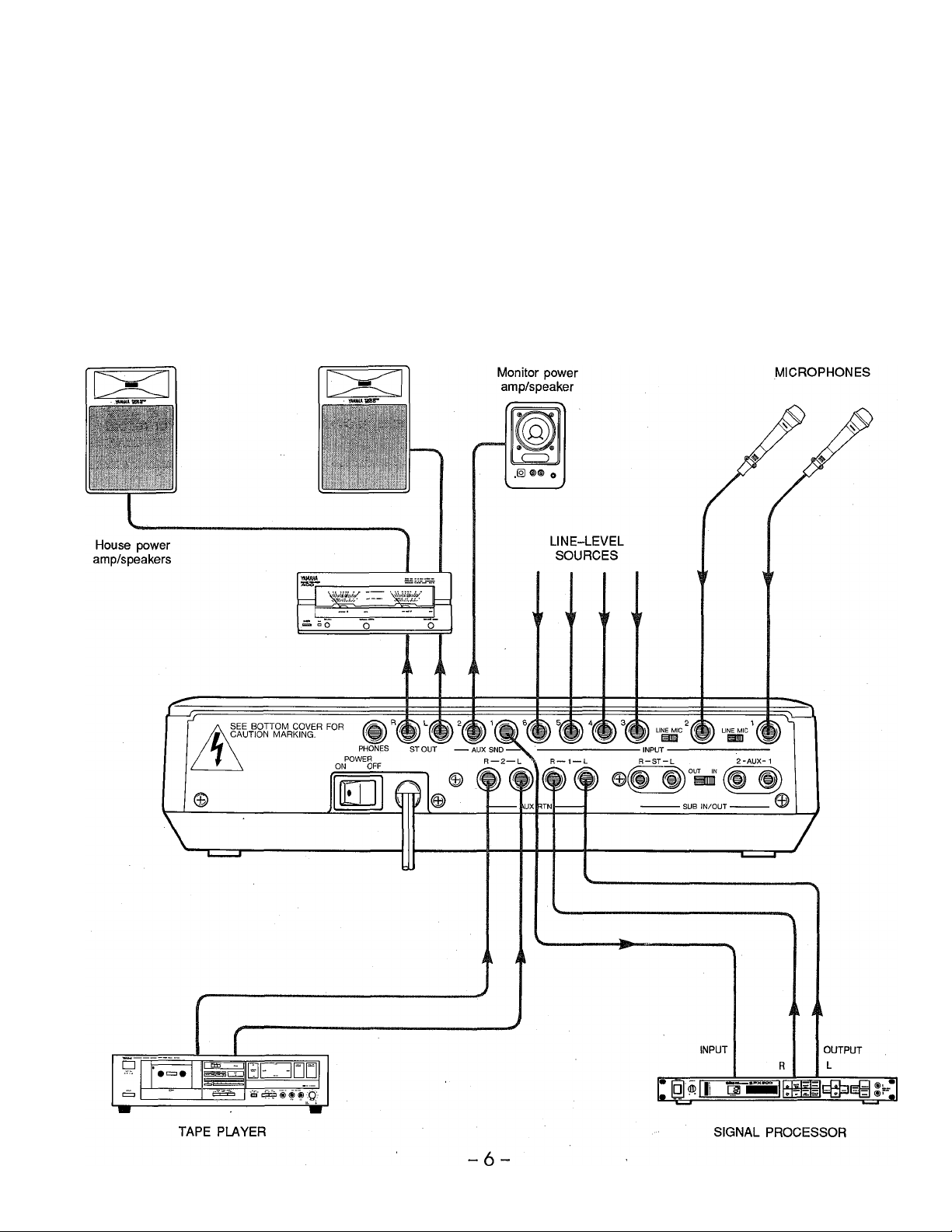
SAMPLE APPLICATION
A Small Sound Reinforcement System
In this small sound reinforcement system the required sources are connected to the appropriate input channel connec
tors. The AUX SND 1 output is connected to a digital signal processor for reverb and other effects, and the stereo
output from the signal processor is returned to the AUX RTN 1 connectors. The AUX 1 controls can thus be used to set
up the required effect mix..The AUX 2 controls are used to provide a separate monitor mix for the performers on stage.
The AUX SND 2 output is therefore connected to a power amplifier driving the on-stage monitor speaker system. The
main house power amplifier/speaker system can be fed by the ST OUT L and R outputs. In this system a tape player
is connected to the AUX RTN 2 inputs to provide background music during intermission or recorded accompaniment for
the performance.
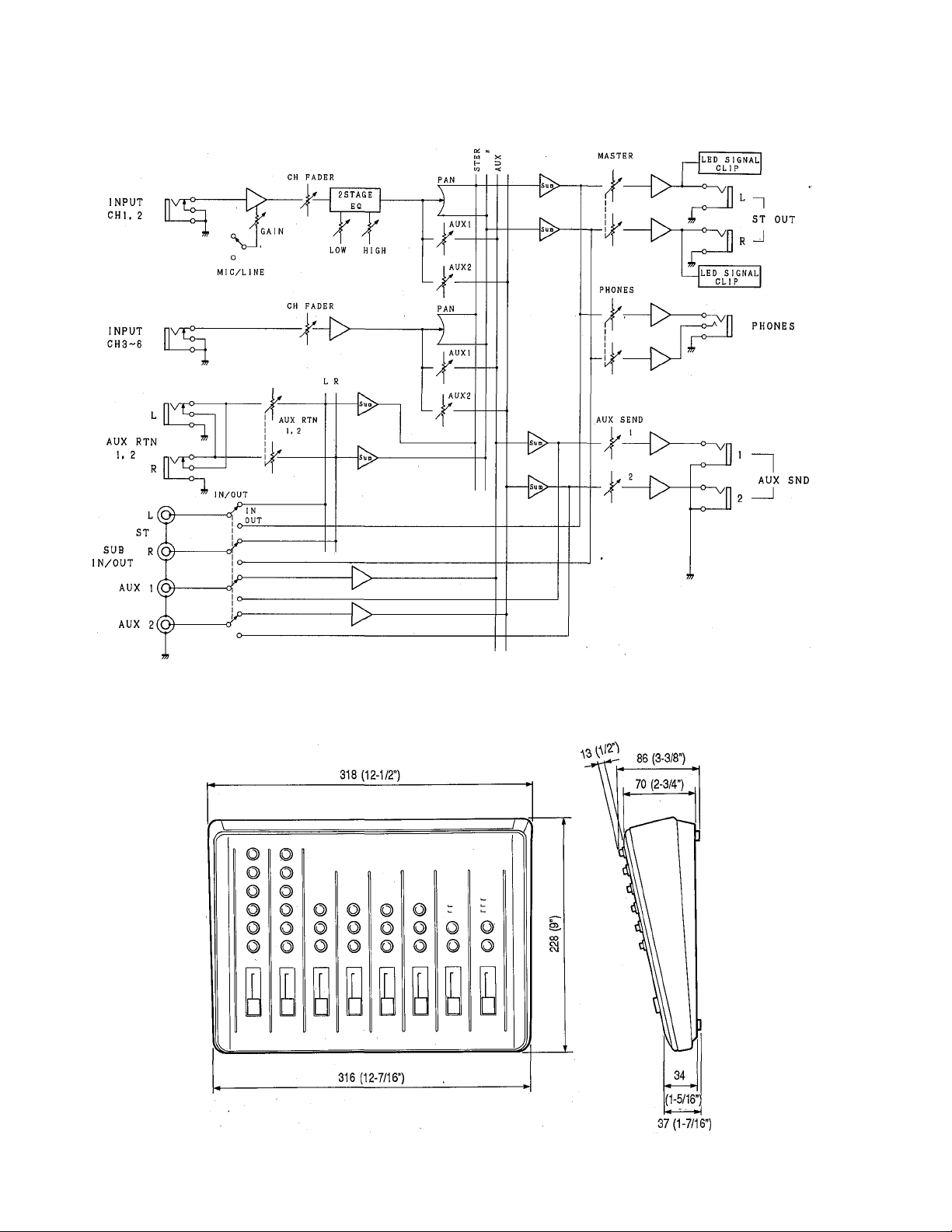
BLOCK DIAGRAM
j oe: a
o u
z
DIMENSIONS
UNIT = mm (inch)
7 -

SPECIFICATIONS
Frequency Response
+1. -2 dB, 20 Hz — 20 kHz. 10 kohms, 0 dB (ST
OUT)
+1, -2 dB. 20 Hz — 20 kHz. 10 kohms. -10 dB
(AUX SND 1. 2). (SUB OUT)
Total Harmonic Distortion
Less than 0.05%. 20 Hz •
+10 dB
20 kHz. 10 kohms.
Hum & Noise* (20 Hz — 20 kHz, Rs = 150
ohms, CHI, 2 Gain max.)
-122dB(CH1. 2) equivalent input noise.
-90 dB (ST OUT) residual output noise.
-76 dB (76 dB S/N) at ST OUT. Master fader
nominal, all channel faders minimum.
-72 dB (72 dB S/N) at ST OUT. Master fader
nominal, channel 1. 2 faders nominal.
-88 dB (78 dB S/N) at AUX SND. all channel
AUX controls minimum.
-82 dB (72 dB S/N) at channei 1.2 faders nomi
nal. AUX controls nominal.
Maximum Output Levei
+17.5 dB. 20 Hz — 20
0.2%
kHz. 10 kohms. THD
Maximum Voitage Gain
62 dB
22 dB
58
18 dB
32 dB
16 dB
6 dB
CHI.2IN to STOUT
CH3—6 IN to ST OUT
dB
CHI.2IN to
—
CH3
AUX RTN to
SUBIN(ST)
SUBIN(AUX) to AUX SND
AUX SND
6 IN
to AUX SND
ST OUT
to ST OUT
Crosstalk
-60 dB at 1 kHz. adjacent channel inputs.
-60 dB at 1 kHz. input to output.
Input Channel Equalization (CHI, 2)
15 dB maximum boost or cut
HI: 10 kHz (shelving)
LO: 100 Hz (shelving)
Ciip Indicators (ST L, R)
CUP (red) lights when ST OUT signai is 3 dB
beiow clipping.
Signai Indicators (ST L, R)
SIGNAL (green) lights when ST OUT signal
reaches -10 dB (10 dB below nominal output
level.)
Power Requirement
Power requirements match local AC mains volt
age and frequency in area where sold.
Power Consumption
9 watts
Dimensions (W x H x D)
318 X 86 X 228 mm (12-1/2” x 3-3/8” x 9”)
Weight
1.8 kg (3 lbs. 15 oz)
* Measured with a -6 dB/octave LPF @ 12.7 kHz.
• 0 dB = 0.775 Vrms
-8-
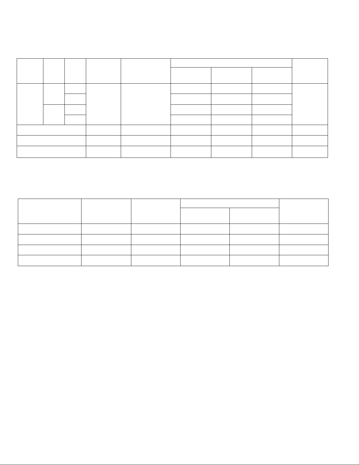
INPUT CHARACTERISTICS
Input
terminals
InputSWGain
Trim
Actual Load
Impedance
For Use With
Nominal
Sensitivity*
Input Level
Nominal
Maximum
before clip
Connector
In Mixer
MIC
CH 1, 2
LINE
CH 3 — 6 Input
AUX RTN 1, 2
SUB IN
MAX
MIN
10 kohms
MAX
MIN
10 kohms
10 kohms 600 ohms Lines
10 kohms 600 ohms Lines
OUTPUT CHARACTERISTICS
Output terminals
ST OUT 600 ohms
AUX SND 1, 2 600 ohms
PHONES
SUB OUT
Actual Source
Impedance
100 ohms
600 ohms
-62dB (0.62mV)
50-600 ohms Mies
& 600 ohms Lines
600 ohms Lines -22dB (62mV)
-37dB (11 mV) -25dB (44mV) -3dB (549mV)
-43dB (5.5mV)
-22dB (62mV)
-32dB (19mV)
-16dB (123mV)
For Use With
Nominal
10 kohms Lines
10 kohms Lines
8 ohms Phones
10 kohms Lines
Nominal
OdB (0.775V)
-lOdB (245mV)
-22dB (62mV)
-lOdB (245mV) +17.5dB (5.8V)
-50dB (2.5mV) -28dB (31 mV)
-31 dB (22mV)
-lOdB (245mV) +12dB (3.1V)
-lOdB (245mV)
-20dB (78mV)
-lOdB (245mV)
-9dB (275mV)
Output Level
Maximum
before clip
+17.5dB (5.8V) Phone jack
+17.5dB (5.8V) Phone jack
-4.5dB (462mV)
STEREO Phone jack
Phone jack
Phone jack
Phone jack
RCA Pin jack
Connector
In Mixer
RCA Pin jack
• 0 dB = 0.775 V
• All Phone Jack are unbalanced.
• Sensitivity is the lowest level that will produce an output of 0 dB (0.775 V), or the nominal output level when the unit
is set to maximum gain.
-9

IMPORTANT NOTICE FOR THE UNITED KINGDOM
Connecting the Plug and Cord
IMPORTANT. The wires in this mains lead are coloured in accordance with the following code:
BLUE : NEUTRAL
BROWN : UVE
As the colours of the wires in the mains lead of this apparatus may not correspond with the
coloured markings identifying the terminals in your plug proceed as follows:
The wire which is coloured BLUE must be connected to the terminal which is marked with the
letter N or coloured BLACK.
The wire which is coloured BROWN must be connected to the terminal which is marked with
the letter L or coloured RED.
SERVICE
This product is supported by YAMAHA's worldwide network of
factory trained and qualified dealer service personnel. In the event
of a problem, contact your nearest YAMAHA dealer.
- 10-

TABLE DE MIXAGE
AÜVl
MANUEL D'INSTRUCTIONS

Félicitations!
Votre AM602 est me table de mixage de haute performance à 6 entréeslll sorties qui vous procu
rera une qualité sonore incomparable et que vous pourrez utiliser dans une grande variété
d'applications.
Afin de tirer le maximum de toutes les fonctions offertes par la AM602, nous vous conseillons vive
ment de lire très attentivement ce manuel d’instructions et de le conserver dans un lieu sûr cfin de
pouvoir vous y reporter ultérieurement si besoin est.
TABLE DES MATIERES
PRECAUTIONS ET CONSEILS DE SECURITE .................................................................13
COMMANDES ET CONNECTEURS
COMMANDES ............................................................................................................ 15
Canaux d’e ntrée
Section de commande principale
CONNECTEURS ........................................................................................................ 17
EXEMPLE D’APPLICATION .............................................................................................. 19
SCHEMA DE PRINCIPE...................................................................................................... 20
DIMENSIONS ............................................................................................................. ....20
SPECIFICATIONS............................................................................................................ .21
HIPSOGRAMME.................................................................................................................. 35
................
................................................................................
................................................................................. 15
........................................................................
14
16
- 12 -

PRECAUTIONS ET CONSEILS DE SECURITE
1. EVITER CHALEUR, HUMIDITE, POUSSIERE
ET VIBRATIONS EXCESSIVES
Ne pas placer l'appareil là où il pourrait être soumis
à des températures ou à une humidité excessives,
comme par exemple à proximité d’un radiateur,
d’un calorifère, etc. Eviter également les endroits
particuiièrement poussiéreux ou soumis à des vi
brations qui pourraient provoquer des dommages
mécaniques.
2. EVITER LES CHOCS
Des chocs physiques violents peuvent endom
mager l’appareil. Par conséquent le manipuler avec
soin.
3. NE PAS OUVRIR L’APPAREIL ET NE PAS
ESSAYER DE LE REPARER OU DE LE
MODIFIER SOI-MEME
Ce produit ne contient pas de pièces réparables
par l’utilisateur. Pour l’entretien et les réparations,
toujours s’adresser à un réparateur YAMAHA qual
ifié. Le fait d’ouvrir l’appareil et/ou d’altérer les
circuits internes annulerait la garantie.
5. MANIPULER PRECAUTIONNEUSEMENT
LES CABLES
Brancher et débrancher les câbles, y compris ie
cordon d’aiimentation, en saisissant le connecteur,
jamais en tirant sur le câble.
6. NETTOYER AVEC UN CHIFFON DOUX ET
SEC
Ne jamais utiiiser de solvants, tels que la benzine
ou un dissolvant, pour nettoyer l’appareil.
L’essuyer simplement avec un chiffon doux et sec.
7. UTILISER TOUJOURS UNE SOURCE
D’ALIMENTATION QUI CONVIENNE
Vérifier que la tension secteur utilisée est la même
que celle indiquée sur ie panneau arrière de
l’appareii.
4. AVANT DE PROCEDER AUX CONNEXIONS
OU AUX DEBRANCHEMENTS, CON
FIRMER QUE L’APPAREIL EST HORS TEN
SION
Avant de brancher ou de débrancher les cordons
toujours mettre l’appareil hors tension. Cette
démarche est importante, car elie permet d’éviter
tout dommage à l’appareil, ainsi qu’aux autres
composants raccordés.
- 13 -

COMMANDES ET CONNECTEURS
PANNEAU DE COMMANDE
(ir
0
YAMAHAmixerAIÎVII
©
0
©-
FACE ARRIERE
^
-----------
» CLIP
> SIGNAL
a POWER
a CLIP •
a SIGNAL«
(D
-O
I
6 U MASTER U PHONES
--
< \ <
----------
D

COMMANDES
• Canaux d’entrée
O Commutateurs micro/Iigne (MIC/LINE)
(Face arrière) — Canaux 1 et 2
Ces commutateurs permettent de régler la sensibilité
d’entrée pour qu’elle corresponde au niveau de micro
phone ou de ligne de la source. En cas de raccorde
ment à une souce de niveau de ligne, comme par
exemple un clavier électronique ou un appareil audio,
mettre le commutateur sur la position LINE. En cas
de raccordement d’un microphone ou de toute autre
source de niveau bas, le mettre sur la position MIC.
O Commandes GAIN — Canaux 1 et 2
Ces commandes permettent de régler la sensibilité
d’entrée du canal correspondant. Ces commandes de
gain réglables d’une manière continue permettent de
réaliser l’équilibre avec pratiquement n’importe
quelles sources de ligne ou de microphone.
@ Commandes d’égalisation LO et HI
— Canaux 1 et 2
Ces commandes permettent de modifier individuelle
ment la réponse en fréquence de chaque canal. Les
commandes d’égalisation LO et HI ont les fonctions
suivantes:
Commande
HI ±15 dB
LO +15 dB 100 Hz Coupure
Plage Fréq. Type
10 kHz Coupure
O Commandes AUX
Les commandes AUX 1 et AUX 2 de AM602 per
mettent de déterminer le niveau du signal du canal
correspondant transmis aux bus de mixage AUX 1 et
AUX 2. Les bus de mixage AUX alimentent alors les
commandes de niveau AUX SND et ensuite les prises
de sortie AUX SND correspondantes de la face
arrière. Les commandes AUX peuvent être utilisées
pour produire deux mixages indépendants pouvant
être transmis à des unités d’effet externes, à un
casque d’écoute via le système monitor individuel, ou
à tout autre système alimenté par les prises AUX
SND. Les commandes AUX sont “post-EQ/post curseur”, ce qui veut dire que les signaux sont captés
en aval de l’étage d’égalisation et des curseurs. Ceci
signifie que les signaux AUX sont affectés par les
réglages d’égalisation et de curseur de canal.
0
Commandes PAN
Les commandes PAN permettent d’assigner le signal
du canal correspondant à n’importe quelle position
dans le champ sonore stéréo. Si une commande
PAN est réglée à fond sur la position “L” (GAUCHE),
le signal du canal correspondant ne sera appliqué
qu’à la sortie de canal gauche (ST OUT L). Si une
commande PAN est réglée à fond sur la position “R”
(DROITE), le signal du canal correspondant ne sera
appliqué qu’à la sortie de canal droit (ST OUT R). Si
une commande PAN est réglée sur la position cen
trale, le signal sera appliqué de manière identique aux
sorties de canal gauche et de canal droit et le son
semblera parvenir au centre du champ sonore stéréo
(en un point à égale distance des deux enceintes
acoustiques). Les autres positions des commandes
PAN placent le son à une position correspondant
approximativement au réglage de ces commandes, et
ce en variant le niveau des signaux appliqués aux
sorties de canal gauche et de canal droit.
-15-
!~:^i
ENCEINTE
GAUCHE
\l/
PAN
ENCEINTE
DROITE
\i/
iX
• . ■ .M.".

0 Curseur de canal
C’est la commande de niveau principale de chaque
canal d’entrée. Chaque curseur permet de régler le
niveau du signal que le canal d’entrée correspondant
transmet aux bus stéréo principal. Le réglage des
curseurs de canal d’entrée détermine le “mixage” ou
équilibre des niveaux du son entre ies divers instru
ments ou autres sources connectées aux entrées.
r REMARQUE: ------------------------------------------
Lorsqu’un canal n’est pas utilisé, son curseur doit
être réglé sur la position minimale pour prévenir
toute addition de bruit au signaux de programme
principaux.
• Section de commande principale
O Commandes de niveau de transmission
(AUX SND)
Ces commandes permettent de régler le niveau de
sortie d’ensembie des “mixages” AUX 1 et AUX 2
préparés en utilisant les commandes AUX correspon
dantes. La commande AUX SND 1 règle le niveau
d’ensembie du signal de mixage AUX 1 appliqué à la
prise AUX SND 1 et AUX SND 2 régie celui du signal
de mixage AUX 2 appliqué à la prise AUX SND 2.
Ces commandes doivent être utilisées pour optimiser
i’équilibre entre le niveau de sortie AUX SND de la
table de mixage et la sensibilité d’entrée de l’unité de
traitement de signai ou de l’ampiificateur de puis
sance externe utilisé.
O Commandes de niveau de retour
(AUX RTN)
Ces commandes permettent de régler le niveau du
signai reçu aux prises AUX RTN correspondantes de
ia face arrière et appiiqué au programme principai du
bus stéréo principal. Des entrées stéréo sont prévues
pour chaque entrée AUX RTN, ce qui assure la com
patibilité avec ies processeurs de signal du type à
entrée mono/sortie stéréo que l’on trouve actuelle
ment sur le marché.
0 Commande de niveau de casque
(PHONES)
Elle permet de régler le niveau du signai de pro
gramme stéréo principal appliqué à la prise PHONES
de la face arrière. Utiiiser la commande PHONES
pour régler le volume du casque d’écoute à un niveau
confortable.
0 Indicateurs de niveau
La table AM602 est pourvue d’un indicateur à LED
CUP et d’un indicateur à LED SIGNAL pour le canal
gauche et pour le canal droit. Les indicateurs SIG
NAL s’allument lorsqu’un signal d’un niveau suffisam
ment élevé est détecté dans le canal correspondant.
Les indicateurs CLIP s’allument lorsque le signal du
canal correspondant atteint 3 dB au-dessous du ni
veau d’écrêtage. Les indicateurs CLIP ne devraient
s’allumer que pour les crêtes de niveau éievé; s’iis
s’ailument plus souvent, le niveau des curseurs ou le
niveau des sources connectées aux entrées de la
table doit être réduit afin de prévenir une distorsion du
son due à une surcharge.
0 interrupteur d’alimentation (POWER)
(Face arrière)
Placer sur la position ON pour mettre la table de
mixage sous tension et sur la position OFF pour la
mettre hors tension. Le témoin à LED POWER
s’aiiume lorsque la table est sous tension.
|- ATTENTiON: -------------------------------------------
Veiiier à ce que le curseur MASTER soit mis au ni
veau minimal avant de mettre la table de mixage
sous tension.
0 Curseur principal (MASTER)
Le curseur MASTER permet de régler le niveau de
sortie du canal gauche et du canal droit et donc le
niveau des signaux appiiqués aux prises ST OUT L et
R.
-16-

COMMAIMDES ET CONNECTEURS
CONNECTEURS
® Connecteurs d’entrée (INPUT)
La table de mixage AM602 est pourvue de 6 canaux
d’entrée, chacun ayant une seule prise jack INPUT
mono de 1/4". La description des commutateurs MIC/
LINE associés aux prises INPUT 1 et 2 est donnée
sous le titre: “O Commutateurs micro/ligne (MIC/
LINE)”. Lorsqu’un commutateur MIC/LINE est mis sur
la position MIC, le niveau et l’impédance d’entrée du
canal correspondant sont réglés à -50 dB/50—600
ohms. Sur la position LINE, le niveau et l’impédance
d’entrée du canal correspondant sont réglés à -10
dB/600 ohms. Le niveau et l’impédance d’entrée des
canaux non pourvus d’un commutateur MIC/LINE
sont de -10 dB/600 ohms.
® Prises de transmission (AUX SND)
Ces prises fournissent respectivement les mixages
AUX 1 et AUX 2 pour la transmission à un processeur
de signal externe, un système d’écoute de contrôle,
etc. Le niveau/impédance de sortie nominal des
prises AUX est de -10 dB/10 kohms.
® Prises de retour (AUX RTN)
Les sorties des processeurs de signal alimentés par
les prises AUX SND peuvent être renvoyées au bus
stéréo principal via ces prises. Les prises AUX RTN
stéréo sont compatibles avec une grande variété de
processeurs de signal du type à entrée mono/sortie
stéréo que l’on trouve actuellement sur le marché.
Les prises AUX RTN peuvent également être utilisées
pour ajouter des signaux externes, autres que ceux
en provenance d’un processeur de signal, au bus
stéréo principal. Le niveau/impédance d’entrée nomi
nal de ces prises est de -20 dB/600 ohms.
Prise de casque d’écoute (PHONES)
La prise PHONES permet d’appliquer le signal de
programme stéréo principal à un casque d’écoute
stéréo standard de 8 ohms. Le niveau d’écoute de
contrôle peut être réglé à l’aide de la commande de
niveau PHONES.
Prises de sortie stéréo gauche et droite (ST OUT L et R)
Il s’agit des sorties principales du bus stéréo de la
table de mixage. Ces prises de type jack de 1/4"
sortent le signal de bus stéréo à 0 dB/10 kohms
(nominal).
® Prises d’entrée/sortie (SUS iN/OUT)
Ces quatre prises prises et le sélecteur permettent de
mettre en cascade deux tables de mixage AM602 afin
d’augmenter le nombre total de canaux d’entrée dis
ponibles de 6 à 12. Lorsque deux tables AM602 sont
utilisées, une fonctionne comme une table pilote et
l’autre comme une table asservie. Les canaux
d’entrée de la table asservie sont utilisés normale
ment, alors que la section de commande principale de
cette table n’est pas utilisée. Les canaux d’entrée de
la table pilote sont également utilisés normalement et
sa section de commande principale sert à contrôler
tout le système. Ceci revient à dire que le curseur
MASTER et les commandes AUX SND et AUX RTN
de la section de commande principale de la table pi
lote affectent les 12 canaux. Le sélecteur SUB IN/
OUT détermine si les prises SUB IN/OUT fonctionne
ront en tant qu’entrée ou en tant que sortie et par
conséquent si la table de mixage sera pilote ou asser
vie. Pour la table asservie, mettre le sélecteur SUB
IN/OUT sur la position “OUT” et pour la table pilote le
mettre sur la position “IN”. Le schéma suivant montre
comment effectuer les raccordements et comment
régler les sélecteurs.
REMARQUE:
En cas d’utilisation normale d’une seule table de
mixage, le sélecteur SUB IN/OUT doit être mis sur
la position “IN”. Dans ce cas, les prises SUB IN/
OUT L et R, AUX 1 et AUX 2 fonctionnent toutes
comme des entrées et peuvent être utilisées pour
appliquer des signaux externes de niveau de ligne
au bus stéréo principal et aux bus AUX de la table
de mixage. Si le sélecteur SUB IN/OUT est mis sur
la position OUT, par contre, les prises SUB IN/OUT
L et R peuvent être utilisées comme des prises
“REC OUT”, fournissant un signal de niveau de
ligne pour l’enregistrèment, etc.
-------------------------------
----------
-17 -

njtiliser les commandes et priseT^
I AUX SND et AUX RTN de la table |
I AM6G2 pilote. Utiliser le curseur i
j^ASTER de la table AM602 pilote.
ST OUT
___
j
REMAQUES IMPORTANTES
VEILLER A CE QUE LA TABLE DE MIXAGE SOIT HORS TENSION OU A CE QUE LE CURSEUR MASTER
SOIT REGLE AU MINIMUM AVANT DE CONNECTER OU DECONNECTER LES CABLES.
TOUJOURS METTRE LA TABLE SOUS TENSION OU AUGMENTER LE REGLAGE DE SON CURSEUR MAS
TER APRES AVOIR MIS SOUS TENSION LES APPAREILS CONNECTES, TELS QU’INSTRUMENT ELEC
TRONIQUE. ETC.
NE JAMAIS CONNECTER LA SORTIE D’ENCEINTE ACOUSTIQUE D’UN AMPLIFICATEUR AUX ENTREES DE
LA TABLE DE MIXAGE A MOINS D’UTILISER UN ATTENUATEUR DE HAUT NIVEAU OU UNE “BOITE DI
RECTE” APPROPRIE POUR ABAISSER LE NIVEAU DES SIGNAUX.
- 18

Dans ce système simple de renforcement du son, les sources requises sont reliées aux connecteurs de canal d’entrée
appropriés. La sortie AUX SND 1 est connectée à un processeur de signal numérique, afin d’appliquer des effets de
réverbération ou autres, alors que la sortie stéréo du processeur est renvoyée aux connecteurs AUX RTN 1. Les com
mandes AUX 1 peuvent ainsi être utilisées pour préparer le mixage d’effets requis. Les commandes AUX 2 sont
utilisées pour transmettre un mixage d’écoute de contrôle indépendant sur scène. La sortie AUX SND 2 est par
conséquent connectée à un amplificateur de puissance qui pilote les enceintes de contrôle sur scène. Le système
amplificateur de puissance/enceintes principal peut être alimenté par les sorties ST OUT L et R. Dans ce système un
lecteur de bande est connecté aux entrées AUX RTN 2 pour fournir une musique de fond pendant les interludes ou un
accompagnement enregistré pendant la performance.

SCHEMA DE PRINCIPE
DIMENSIONS
-20-
^3 ^M2.’ì
86 (3-3/8')
37 (1-7/16")
UMÌTE =
mm

SPECIFICATIONS
Réponse en fréquence
+1. -2 dB, 20 Hz — 20 kHz, 10 kohms, 0 dB (ST
OUT)
+1. -2 dB, 20 Hz — 20 kHz, 10 kohms, -10 dB
(AUXSND 1, 2), (SUB OUT)
Distorsion harmonique totale
Moins de 0,05%, 20 Hz — 20 kHz, 10 kohms,
sortie +10 dB
Bourdonnement et bruit* (20 Hz — 20 kHz, Rs = 150 ohms, Gain maxi, CH1, 2)
-122dB(CH1, 2) bruit d’entrée équivalent
-90 dB (ST OUT) bruit de sortie résiduel
-76 dB (S/B 76 dB) à ST OUT, curseur principal
nominal, tous les curseurs de canal au
minimum.
-72 dB (S/B 72 dB) à ST OUT, curseur principal
et curseurs de canal 1 et de canal 2
nominal.
-88 dB (S/B 78 dB) à AUX SND, toutes les
commandes AUX de canal au minimum.
-82 dB (S/B 72 dB) à curseur de canal 1 et de
canal 2 nominal, commandes AUX
nominal.
Niveau de sortie maximal
+17,5 dB, 20 Hz — 20 kHz, 10 kohms, DHT
0,2%
Gain de tension maximal
62 dB, de CH1, 2 IN à ST OUT
22 dB, de CH3 — 6 IN à ST OUT
58 dB, de CH1, 2 IN à AUX SND
18 dB, de CH3 — 6 IN à AUX SND
32 dB, de AUX RTN à ST OUT
16 dB, de SUB IN (ST) à ST OUT
6 dB, de SUB IN (AUX) à AUX SND
Diaphonie
-60 dB à 1 kHz, entrées de canaux adjacents
-60 dB à 1 kHz, d’entrée à sortie
Egalisation de canal d’entrée (CHI, 2)
Accentuation ou atténuation maximale de 15 dB
HI: 10 kHz (coupure)
LO: 100 Hz (coupure)
Témoins de crête (ST L, R)
Témoin CLIP (rouge) s’allume lorsque le signal
ST OUT est 3 dB au-dessous du niveau
d’écrêtage.
Indicateurs de niveau (ST L, R)
SIGNAL (vert) s’allume lorsque le signal ST
OUT atteint -10 dB (10 dB au-dessous du ni
veau de sortie nominal.)
Alimentation électrique
Conforme à l'alimentation secteur (tension et
fréquence) utilisée dans la région où l'appareil a
été acheté.
Consommation électrique
9 watts
Dimensions (L x H x P)
318 X 86 X 228 mm
Poids
1,8 kg____________
* Mesurés avec un FPB de -6 dB/octave à 12,7 kHz
• 0 dB = 0,775 V eff.
_____________________
-21 -

CARACTERISTIQUES D’ENTREE
Bornes
d’entrée
Commu
tateur
Input
MIC
Entrée
CH 1, 2
UNE
Entrée CH 3 — 6
AUX RTN 1, 2
SUB IN
Atténuation
de gain
MAX
MIN -37dB (llmV) -25dB (44mV) -3dB (549mV)
MAX
MIN -22dB (62mV)
Impédance
de charge
effective
10 kohms
10 kohms
10 kohms
10 kohms
CARACTERISTIQUES DE SORTIE
Bornes de sortie
STOUT
Impédance de
source effective
600 ohms
Pour utilisation à
nominal
Micro 50-600 ohms
et
Ligne 600 ohms
Ligne 600 ohms -22dB (62mV) -lOdB (245mV)
Ligne 600 ohms -32dB (19mV) -20dB (78mV)
Ligne 600 ohms -16dB (123mV) -lOdB (245mV)
Sensibilités* Nominai
-62dB (0,62mV)
-43dB (5,5mV) -31 dB (22mV)
Pour utilisation à
nominal
Ligne 10 kohms OdB (0,775V)
Niveau d’entrée
-50dB (2,5mV) -28dB (31mV)
-lOdB (245mV) +12dB (3,1V)
Niveau de sortie
Nominal
Maximum avant
Maximum
avant écrêtage
-9dB (275mV)
Connecteur
de la table
Prise jack
Prise jack
Prise jack
Prise à broches
RCA
Connecteur de la
table
écrêtage
+17,5dB (5,8V) Prise jack
AUX SND1, 2
PHONES
SUB OUT
600 ohms
100 ohms Casque 8 ohms -22dB (62mV)
600 ohms Ligne 10 kohms -lOdB (245mV) +17,5dB (5,8V)
Ligne 10 kohms -lOdB (245mV)
+17,5dB (5,8V) Prise jack
-4,5dB (462mV)
Prise jack STEREO
Prise à broches RCA
• 0 dB = 0,775 V eff.
• Toutes les prises jacks sont asymétriques
• La sensibilité est le niveau le plus bas produisant une sortie de 0 dB (0,775 V), ou ie niveau de sortie nominal
lorsque le gain de la table est réglé au maximum.
ENTRETIEN
L'entretien de cet appareil est assuré par le réseau mondial
YAMAHA de personnel d'entretien qualifié et formé en usine des
concessionnaires. En cas de problème, prendre contact avec le
concessionnaire YAMAHA le plus proche.
22

MISCHPULT
AiVi
BEDIENUNGSANLEITUNG

Ihr AM602 ist ein hochwertiges Mischpult mit 6 Eingangskanalzügen und zwei Ausgangskanälen, das
sich durch hervorragende klangliche Leistungen auszeichnet und dank der umfassenden Signal
wegsteuerung vielseitige Einsatzmöglichkeiten bietet.
Bitte lesen Sie diese Bedienungsanleitung sorgfältig durch, um die vielseitigen Funktionen und das
Potential Ihres AM602 voll ausnutzen zu können und bewahren Sie diese Anleitung zur späteren
Bezugnahme ari einem sicheren Ort aif.
INHALT
Herzlichen Glückwunsch!
VORSICHTSMASSNAHMEN .............................................................................................25
BEDIENELEMENTE UND ANSCHLÜSSE..........................................................................26
BEDIENELEMENTE....................................................................................................27
Eingangskanäle ................................................................................................... 27
Stereobus-Bedienungsmodul
ANSCHLÜSSE ........................................................................................................... 29
ANWENDUNGSBEISPIEL .................................................................................................31
BLOCKDIAGRAMM
ABMESSUNGEN................................................................................................................. 32
TECHNISCHE DATEN ........................................................................................................33
PEGELDIAGRAMM............................................................................................................ 35
.........
................................................................................................. 32
............................................................................
28
-24 -

VORSICHTSMASSNAHMEIM
1. V0R UBERMASSIGER HITZE, FEUCHTIG
KEIT, STAUB UND VIBRATION SCHÜTZEN
Das Gerät nicht an Orten aufstellen, die hohen
Temperaturen oder Feuchtigkeit ausgesetzt sind,
wie z. B. in der Nähe von Heizkörpern, Öfen usw.
Außerdem Aufstellorte vermeiden, an denen
übermäßig Staub oder Vibration auftritt, um das
Gerät vor Schäden zu bewahren.
2. VOR FALL UND STOSS SCHÜTZEN
Fall und Stoß können Schäden am Gerät ver
ursachen. Daher mit der gebotenen Umsicht hand
haben.
3. NIEMALS DAS
EIGENHÄNDIG
GERAT OFFNEN ODER
REPARATUREN AUS-
FÜHREN
Dieses Gerät enthält keine vom Laien zu warten
den Teile. Alle Reparatur- und Wartungsarbeiten
von einer qualifizierten YAMAHA-Kundendienst-
stelle durchführen lassen. Das Öffnen des
Gehäuses und/oder Verändern von internen
Schaltkreisen führt zum Garantieverlust.
5. KABEL VORSICHTIG HANDHABEN
Beim Anschließen und Abtrennen von Kabeln,
einschließlich des Netzkabels, das Kabet stets am
Stecker fassen.
6. MIT EINEM TROCKENEN WEICHEN TUCH
REINIGEN
Zum Reinigen niemals Benzin oder Verdünner ver
wenden. Mit einem trockenen weichen Tuch ab
wischen.
7. AUF KORREKTE NETZSPANNUNG ACH
TEN
Sicherstellen, daß die Betriebsspannungswerte auf
der Rückseite der örtlichen Netzspannung ent
sprechen.
VOR DEM ANSCHLUSS ALLE GERATE
AUSSCHALTEN
Vor dem Anschließen oder Abtrennen von Kabeln
alle Geräte AUSschalten, um Schäden durch
Schaltimpulse am Mischpult selbst und den an
deren Geräten zu verhindern.
-25
BEDIENELEMENTE UND ANSCHLÜSSE
BEDIENUNGSKONSOLE
©-
YAMAHA.,xehABVI
©-
©
V
RÜCKSEITE
> CLIP
> SIGNAL
6 u MASTER u PHONES
< i <
3 POWER
S CLIP •
3 SIGNAL*
AUXSND1 I-
O—T
0 "'=^10
--------
D
-<D
-O

BEDIENELEMENTE
• Eingangskanäle
O Mikrofon/Hochpegel-Schalter (Rückseite)
- Kanäle 1 & 2
Dieser Schalter dient zum Anpassen der Ein
gangsempfindlichkeit der Eingangskanäie 1 und 2 an
Mikrofon- oder Hochpegelquellen. Bei Anschluß einer
Hochpegelquelle wie z. B. eines elektronischen Key
boards den Schalter auf LINE stellen. Bel Anschluß
von Niedrigpegelquellen wie z. B. einem Mikrofon den
Schaiter in Steiiung MIC bringen.
0 Verstärkungsfaktorregler (GAIN)
- Kanäle 1 & 2
Der GAIN-Regier gleicht die Eingangsempfindlichkeit
des entsprechenden Kanals ab. Dank dieser
stufenlosen Regler kann die Eingangsempfindlichkeit
akkurat auf den Ausgangspegel von Mikrofonen oder
Hochpegelquelien abgestimmt werden.
0
2-Band-Entzerreregler (EQ LO & Hl)
' Kanäle 1 & 2
Mit diesen Regiern kann der Frequenzgangverlauf der
Kanäle 1 und 2 individuell gesteuert werden. Der EQ
Hl-Regler (für hohes Frequenzband) und EQ LQRegler (für tiefes Frequenzband) haben folgende
Wirkungseigenschaften:
Regler
Hl
LO ±15 dB
Bereich Freq.
±15 dB
10 kHz
100 Hz
Typ
Kuhschwanzfilter
Kuhschwanzfilter
O Sendewegpegelregler (AUX)
Die Regler AUX1 und AUX 2 des AM602 bestimmen
den Pegel, mit dem das im entsprechenden Kanal
abgegriffene Signal zu den AUX -Bussen 1 und 2
geschickt wird. Der Gesamtsignalpegel der AUXGruppenbusse 1 und 2 wird über die Sendebus-
Pegeiregler (AUX SND 1 und 2) festgelegt. Die
Ausgangssignale der AUX-Gruppenbusse liegen an
den Buchsen AUX SND auf der Rückseite an. Mit den
AUX-Pegelreglern der Eingangskanäle können zwei
separate Mischungen ersteiit werden, um z. B. ein
externes Effektgerät und ein Cue-Kopfhörersystem
usw. zu speisen. Alle AUX-Pegelregler sind hinter der
Entzerrer- und Faderstufe integriert, d. h. daß der
Signaiabgriff hinter diesen Stufen erfolgt und die
AUX-Signaie daher von den Entzerrer- und Faderein
stellungen der jeweiligen Kanäle beeinflußt werden.
0
Panormaregler (PAN)
Dieser Regler teilt das betreffende Kanalsignal zwi
schen dem iinken und rechten Stereobus auf,
wodurch die Signalposition im Stereoklangbild
festgelegt wird. Fails der PAN-Regier z. B. ganz nach
links gedreht ist, liegt das Signal dieses Kanals nur
am linken Stereoausgang an. Faiis der PAN-Regier z.
B. ganz nach rechts gedreht ist, liegt das Signai die
ses Kanals nur am rechten Stereoausgang an. In der
Mittelstellung des PAN-Reglers wird das entsprech
ende Kanaisignai mit gleichem Pegel auf linken und
rechten Stereokanal gelegt. Durch Einstellungen
zwischen den Anschlagpunkten wird das Signal im
Verhältnis zur Reglerstellung auf linken und rechten
Stereokanal verteilt.
-27-
iXJ
LINKER
LAUTSPRECHER
\l/
LAUTSPRECHER
PAN
RECHTER
\l/
/|\
IX

0 Kanalfader
Dies sind die Hauptpegelregler für die einzeinen
Eingangskanäie. Sie legen fest, mit welchem Pegel
das vom entsprechenden Eingangskanal kommende
Signal zum Stereobus geschickt wird. Die Einsteiiungen dieser Fader legen das Lautstärke
verhältnis zwischen den an den Kanaleingängen angeschiossenen instrumenten oder Queiien fest.
HINWEIS:
Falls ein Kanal nicht beschältet ist, sollte der Fader
ganz abgesenkt werden, um Rauscheinstreuungen
in die Programmsignale zu verhindern.
• Stereobus-Bedienungsmodul O Sendebus-Pegelregler (AUX SND 1,2)
Diese Regler legen den Gesamtausgangspegel der
Schleifenbusse AUX 1 und AUX 2 fest. Das Pegel
verhältnis zwischen den einzelnen Kanalsignalen in
den Schleifenbussen wird durch die AUX 1- und AUX
2-Pegelregler der Eingangskanalzüge bestimmt. AUX
SND 1 steuert hierbei den Gesamtpegel des Misch
signals von AUX-Schleifenbus 1, das an der Buchse
AUX SND 1 anliegt, während AUX 2 den Ges
amtpegel des an der Buchse AUX SND 2 anliegen
den Mischsignals regelt. Mit diesen Reglern können
die Ausgangspegel der beiden AUX-Schleifenbusse
optimal an die Eingangsempfindlichkeit von externen
Effektgeräten, Signalprozessoren oder Leistungs
verstärkern angeglichen werden.
® Kopfhörerpegelregler (PHONES)
Der PHONES-Regler bestimmt den Pegel der Stereo
programmsignale, die zur PHONES-Budhse auf der
Rückseite geschickt werden. Die Kopfhörerlautstärke
mit diesem Regler einstellen.
<D Pegelanzeigen
Das AM602 besitzt Signal- (SIGNAL) und Ver
zerrungsanzeigen (CLIP) für linken und rechten Ka
nal. Die SIGNAL-Anzeigen leuchten auf, wenn Sig
nale im Stereobus erfaßt werden. Die CLIP-Anzeigen
hingegen sprechen an, wenn die Signale im ent
sprechenden Stereobus einen Pegel von 3 dB unter
dem Verzerrungspegel erreichen. Es spielt keine
Rolle, wenn die CLIP-Anzeigen gelegentlich aufleuchten. Falls sie jedoch häufig aufleuchten, weist dies
auf eine Übersteuerung hin. In diesem Fall die Fader-
Pegel oder Ausgangspegel der angeschlossenen
Quellen absenken.
® Netzschalter (POWER) (Rückseite)
Zum Einschalten des AM602 den POWER-Schalter
auf der ON-Seite drücken, zum Ausschalten die OFF-
Seite drücken. Bei eingeschaltetem Mischpult leuchtet
die POWER-Anzeige.
VORSICHT:
Vor dem Einschalten des Mischpults unbedingt den
MASTER-Fader ganz absenken.
O Schleifen-Rückgabepegelregler
(AUX RTN 1 & AUX RTN 2)
Diese Regler bestimmen den Pegel des Signals, das
an der entsprechenden AUX RTN-Buchse der
Geräterückseite empfangen und in die Stereobusse
eingeblendet wird. Bei diesen Eingängen handelt es
sich um Stereoeingänge, um Kompatibilität mit
Effektgeräten zu gewährleisten, die einen Mono-Ein-
und Stereo-Ausgang aufweisen.
0 Hauptfader (MASTER)
Der MASTER-Fader legt den Ausgangspegel der
Signale auf linken und rechten Stereokanal fest, die
an den Buchsen ST OUT L und R anliegen.
-28

BEDIENELEMENTE UND ANSCHLÜSSE
ANSCHLÜSSE
® Eingangsbuchsen (INPUT)
Das AM602 verfügt über insgesamt 6 Eingangskanäle
mit jeweils einer 1/4 Zoll Mono-Klinkenbuchse. Siehe
die Beschreibung O MIC/LINE-Schalter hinsichtlich
der Verwendung dieser Schalter bei den
Eingangskanälen 1 & 2. Wenn der MIC/LINE-Schalter
auf MIC gestellt ist, ist der Eingangspegel bzw. die impedanz des entsprechenden Kanals auf -50 dB/50
—600 Ohm eingestellt. In der Schalterstellung LINE
betragen Eingangspegel und -impedanz -10 dB/600
Ohm. Die Eingänge ohne MIC/LINE-Schalter
verfügen über einen Eingangspegel und eine -impe
danz von -IOdB/600 Ohm.
<E> AUX-Bussendebuchsen
(AUX SND 1 & 2 )
An diesen Buchsen liegen die Mischungen der AUX-
Schleifenbusse 1 und 2 an, um diese Signale zu
einem externen Signalprozessor oder Monitorsystem
zu senden. Nennpegel und -impedanz der AUX SND-
Buchsen betragen -IOdB/10 kOhm.
® Linke und rechte
AUX-Schleifenrückgabebuchsen (AUX RTN 1 (L & R), AUX RTN 2 (L & R))
Die Ausgangssignale der Signalprozessoren, die über
die Buchsen AUX SND 1 oder 2 gespeist werden,
können über diese Buchsen zum Stereobus
rückgeführt werden. Die Stereo AUX RTN-Buchsen
gewährleisten Kompatibilität mit herkömmlichen
Signalprozessoren, die einen Mono-Ein- und einen
Stereo-Ausgang besitzen. Über die AUX RTN-
Buchsen können natürlich auch zusätzliche externe
Signale (z. B. von Bandgerät oder CD-Spieler), die
nicht von Prozessoren kommen, in die Stereobusse
eingeblendet werden. NominalpegelZ-impedanz dieser
Buchsen betragen -20 dB/600 Ohm.
# Kopfhörerbuchse (PHONES)
Die PHONES-Buchse gibt das Stereo-Ausgangs-
signal des Mischpults an Standard-Stereokopfhörer
mit 8 Impedanz ab. Der Mithörpegel wird über den
PHONES-Pegelregler justiert.
Linker & rechter Stereo-Ausgang (ST OUT L & R)
An diesen Ausgängen liegt das Hauptprogra'mmsignal
vom Stereobus des Mischpults an. Diese 1/4 Zoll
Klinkenbuchsen geben die Signale des Stereobus mit
einem Nominalpegel von 0 dB und einer Nenn
impedanz von 10 kOhm ab.
(D Nebenein/ausgänge (SUB IN/OUT)
Diese vier Buchsen und der IN/OUT-Wahlschalter er
lauben die Kaskadierung (in Reihe schalten) von zwei
AM602, um die Anzahl der Eingangskanäle von 6 auf
12 zu erhöhen. Wenn zwei AM602 kaskadiert werden,
fungiert eines als Master-Mischpult und das andere
als Sklave. Die Eingangskanalfader des Sklaven
mischpults arbeiten normal, seine Stereomodul-Be
dienelemente sind jedoch außer Funktion gesetzt. Die
Eingangskanal-Bedienelemente des Master-Misch
pults arbeiten ebenso wie gehabt und seine Stereo
modul-Bedienelemente steuern das Stereomischsig
nal des gesamten Systems. Dies bedeutet, daß der
MASTER-Fader und die AUX SND- bzw. AUX RTN-
Reglerdes Master-Mischpults die Abmischfunktion für
alle 12 Kanäle steuern. Der Schalter SUB IN/OUT
bestimmt, ob die SUB IN/OUT-Buchsen als Eingänge
oder Ausgänge arbeiten und damit, ob das AM602 als
Master- oder Sklavenmischpult fungiert. Wenn das
Mischpult als Sklave eingesetzt werden soll, den SUB
IN/OUT-Schalter auf OUT stellen, während bei Ein
satz als Master der Schalter auf IN gestellt werden
muß. Das nachstehende Diagramm zeigt die
Anschlüsse und Schalterstellungen für die Kaska
dierung.
r HINWEIS:
Für den normalen Einzelbetrieb den Schalter SUB
IN/OUT auf IN stellen. In dieser Stellung fungieren
die Buchsen der SUB IN/OUT-Gruppe als
Zusatzeingänge, über die externe Flochpegelsig-
nale in den Stereobus und in die Schleifenbusse
eingeblendet werden können. Falls der Schalter
SUB IN/OUT auf OUT gestellt ist, können die
Buchsen SUB IN/OUT L und R als Aufnahme
ausgänge zum Anschluß eines Tonbandgeräts ver
wendet werden, da sie Hochpegelsignale abgeben.
-------
-------------------------
-------
-29

l~ÄuX SND- und AUX RTN-RegleT^
I sowie MASTER-Fader des Master |
|^M602 verwenden.
__
|
WICHTIGE HINWEISE
VOR DEM ANSCHLUSS ODER ABTRENNEN VON KABELN UNBEDINGT DAS MISCHPULT AUSSCHALTEN
ODER DEN MASTER-FADER GANZ ABSENKEN.
DIE PROGRAMMQUELLEN WIE ELEKTRONISCHE INSTRUMENTE USW. STETS ZUERST UND DANACH
DAS MISCHPULT BEI GANZ ABGESENKTEM MASTER-FADER EINSCHALTEN.
NIEMALS DIE LAUTSPRECHEREINGÄNGE EINES VERSTÄRKERS DIREKT MIT DEN EINGÄNGEN DIESES
MISCHPULTS VERBINDEN, FALLS KEIN DÄMPFUNGSPAD ZUM ABSENKEN DES SIGNALPEGELS
ZWISCHENGESCHALTET IST.
-30-

AIMWEIMDUNGSBEISPIEL
Eine kleine PA-Anlage
Bei dieser kieinen PA-Anlage sind die Queilen an die jeweiis passenden Eingangsbuchsen angeschiossen. Der Sende
bus AUX SND 1 ist mit einem digitalen Signalprozessor verbunden, der die Effektsignaie über die Buchsen RTN 1 zum
Stereobus zurückführt. Die Signalabmischung auf Sendebus AUX SND 1 wird über die AUX 1-Regler der
Eingangskanäle durchgeführt, während der Gesamtpegel über den Regler AUX SND 1 festgelegt wird. Mit den AUX 2-
Regiern kann eine Mithörmischung für die Interpreten auf der Bühne erstellt werden. Der Ausgang AUX SND 2 ist
daher mit einer Endstufe verbunden, die die Monitoriautsprecher auf der Bühne treibt. Die Haupt-Endstufe/Hauptboxen
werden über die Ausgänge ST OUT L und R angesteuert. Bei diesem System wird ein Bandgerät über AUX RTN 2
eingeschieift, um Hintergrundsmusik während Pausen oder Begleitung zu iiefern .

BLOCKDIAGRAMM
ABMESSUNGEN
EINHEIT = mm
32-

TECHNISCHE DATEN
Frequenzgang
+1. -2 dB, 20 Hz - 20 kHz, 10 kOhm, 0 dB (ST
OUT)
+1, -2 dB, 20 Hz - 20 kHz, 10 kOhm, -10 dB
(AUX SND 1,2) (SUB OUT)
Gesamtklirrfaktor
Weniger als 0,05%, 20 Hz - 20 kHz, 10 kOhm,
+10 dB
Brummen & Rauschen* (20 Hz - 20 kHz, Wid
erstand = 150 Ohm, CH 1, 2, GAIN auf Max.)
-122dB(CH 1, 2) Äquivalentes Eingangs
rauschen
-90 dB (ST OUT) Restausgangsrauschen
-76 dB (76 dB Rauschabstand) an ST OUT,
MASTER-Fader auf Nominalwert, alle
Kanal-Fader auf Minimum.
-72 dB (72 dB Rauschabstand) an ST OUT,
MASTER-Fader auf Nominalwert,
Kanal-Fader 1 & 2 auf Minimum.
-88 dB (78 dB Rauschabstand) an AUX SND,
alle Kanal-AUX-Regler auf Minimum
-82 dB (72 dB Rauschabstand) Fader von Ka
nal 1 & 2 auf Minimum, AUX-Regler auf
Nominalwert
Max. Ausgansgpegel
+17,5 dB, 20 Hz — 20 kHz, 10 kOhm, Gesamt
klirrfaktor 0,22%
Max. Spannungsverstärkung
62 dB Kanal 1,2 zu ST OUT
22 dB Kanal 3 - 6 zu ST OUT
dB Kanal 1,2 zu AUX SND
58
dB Kanal 3 - 6 zu AUX SND
18
dB AUX RTN zu ST OUT
32
dB SUB IN (ST) zu ST OUT
16
6 dB SUB IN (AUX) zu AUX SND
Übersprechdämpfung
-60 dB bei 1 kHz, zwischen angrenzenden
Kanälen
-60 dB bei 1 kHz, Eingang zu Ausgang
Eingangskanalentzerrung (Kanal 1, 2}
15 dB Pegelanhebung, -abschwächung max.
Hl: 10 kHz (Kuhschwanzcharakteristik)
LO: 100 Hz (Kuhschwanzcharakteristik)
Verzerrungsanzeigen (ST L, R)
CLIP (rot) leuchtet auf, Stereo-Ausgangssignal 3
dB unter Verzerrungspegel erreicht.
Signalanzeigen (ST L, R)
SIGNAL (grün) leuchtet wenn Signale an ST
OUT einen Pegel von -10 dB erreichen (10 dB
unter Nominal-Ausgangspegel.)
Stromversorgung
Das Mischpult ist bereits auf die Netzspannung
und-frequenz des Bestimmungslandes ein
gestellt.
Leistungsaufnahme
9 W
Abmessungen (B x H xT)
318 X 86 X 228 mm
Gewicht
1.8 kg
* Mit -6dB/Okt. Tiefpaßfilter bei 12,7 kHz gemessen
• 0 dB = 0,775 Veff
^i'iirn
-33

EINGANGSKENNDATEN
Eingangs
buchsen
Eingangs
CH 1,2
Eingangs CH 3 — 6
AUX RTN 1, 2
SUB IN
Input-
Schalter
MIC
LINE
GAIN
MAX
MIN
MAX
MIN
Tatsächliche
Last
impedanz
10 kOhm
10 kOhm
10 kOhm 600 Ohm Hochpegel
10 kOhm
AUSGANGSKENNDATEN
Ausgangsbuchsen
ST OUT 600 Ohm
AUX SND 1, 2
PHONES
SUB OUT
Tatsächliche
Quellenimpedanz
600 Ohm 10 kOhm Hochpegel -lOdB (245mV)
100 Ohm 8 Ohm Hochpegel
600 Ohm
Bei Einsatz mit
Nominalwert
50-600 Ohm Mikr.
und
600 Ohm Hochpegel
600 Ohm Hochpegel
600 Ohm Hochpegel
Bel Einsatz mit
Nominalwert
10 kOhm Hochpegel
10 kOhm Hochpegel
Eingangspegel
Empfindlichkeit*
-62dB (0,62mV)
-37dB (11mV)
-43dB (5,5mV)
-22dB (62mV)
-22dB (62mV)
-32dB (19mV) -20dB (78mV)
-16dB (123mV)
Nominal
OdB (0,775V) +17,5dB (5,8V)
-22dB (62mV)
-lOdB (245mV)
Nominal
-50dB (2,5mV) -28dB (31 mV)
-25dB (44mV)
-31 dB (22mV)
-lOdB (245mV)
-lOdB (245mV)
-lOdB (245mV)
Ausgangspegel
Maximum bevor
+17,5dB (5,8V)
-4,5dB (462mV)
+17,5dB (5,8V)
Maximum bevor
Verzerrung
-3dB (549mV)
-9dB (275mV)
+12dB (3,1V)
Verzerrung
Buchsentyp
Klinkenbuchse
Klinkenbuchse
Klinkenbuchse
Cinchbuchse
Buchsentyp
Klinkenbuchse
Klinkenbuchse
Stereo-
Klinkenbuchse
Cinchbuchse
• OdB = 0,775 Veff
• Alle Kllnkenbuchsen unsymmetrisch.
• Empfindlichkeit ist der niedrigste Eingangspegei, der einen Ausgangspegel von OdB (0,775 V) bewirkt, oder der
den Nominalausgangspegel bei maximaien Gain erzeugt.
KUNDENDIENST
Für dieses Gerät steht das weltweits YAMAHA Kundendienstnetz
mit qualifiziertem, werksgeschultem Personal zur Verfügung. Bei
Störungen und Problemen wenden Sie sich bitte an Ihren
YAMAHA-Händler.
34

LEVEL DIAGRAM
HIPSOGRAMME
PEGELDIAGRAMM
CH
INPUT
CHI, 2 ONLY CH only
AUX RTN
(-20dB)
CH3-6
AUX SUB-
AUX RTN >N
VOL. AUX RTN
BUFFER
—/------------[>
AUX SUB
OUT
STEREO STEREO
MASTER MASTER
FADER BUFFER
-/
----------
AUX SND
MASTER VOL. master
-/
-----------
PHONES VOL. AMP.
1>—
HEADPHONE
-/—o
“^nST OUT
__
U (OdB)
~°^r|AUX SND
__
U (-1 OdB)
■“^riPHONES
__
U (-22dB)
- 35-

YAMAHA
|VH50430l R3 1 PT 92 12 500 CP Printed in JAPAN
YAMAHA CORPORATION
RO.Box 1, Hamamatsu, Japan
 Loading...