

Yamaha A-15-W, A-15, A-10, A-12-M, A-12 Service Manual

SPEAKER SYSTEM/SUBWOOFER
A10/A12/A12M/A15/A15W
SERVICE MANUAL
A10 A12
A15
CONTENTS
SPECIFICATIONS & DIMENSIONS ........................................ 3
NEUTRIK NL4FC PLUG WIRING............................................. 3
CROSSOVER ............................................................................ 4
DISASSEMBLY PROCEDURE ................................................. 9
A10/A12/A15 .......................................................................... 9
A12M .................................................................................... 12
A15W .................................................................................... 15
A12M
A15W
PA
011750
PARTS LIST
Copyright (c) Yamaha Corporation. All rights reserved. PDF-K103 ’04.11
HAMAMATSU, JAPAN
1

SPEAKER SYSTEM/SUBWOOFER
A10/A12/A12M/A15/A15W
IMPORTANT NOTICE
This manual has been provided for the use of authorized Yamaha Retailers and their service personnel. It has been assumed
that basic service procedures inherent to the industry, and more specifically Yamaha Products, are already known and understood by the users, and have therefore not been restated.
WARNING : Failure to follow appropriate service and safety procedures when servicing this product may result in per-
IMPORTANT : This presentation or sale of this manual to any individual or firm does not constitute authorization certifi-
The data provided is belived to be accurate and applicable to the unit(s) indicated on the cover. The research engineering, and
service departments of Yamaha are continually striving to improve Yamaha products. Modifications are, therefore, inevitable
and changes in specification are subject to change without notice or obligation to retrofit. Should any discrepancy appear to
exist, please contact the distributor’s Service Division.
WARNING : Static discharges can destroy expensive components. Discharge any static electricity your body may have
IMPORTANT : Turn the unit OFF during disassembly and parts replacement. Recheck all work before you apply power
sonal injury, destruction of expensive components and failure of the product to perform as specified. For
these reasons, we advise all Yamaha product owners that all service required should be performed by an
authorized Yamaha Retailer or the appointed service representative.
cation, recognition of any applicable technical capabilities, or establish a principal-agent relationship of
any form.
accumulated by grounding yourself to the ground bus in the unit (heavy gauge black wires connect to
this bus.)
to the unit.
WARNING: CHEMICAL CONTENT NOTICE!
The solder used in the production of this product contains LEAD. In addition, other electrical/electronic and/or plastic (Where
applicable) components may also contain traces of chemicals found by the California Health and Welfare Agency (and possibly
other entities) to cause cancer and/or birth defects or other reproductive harm.
DO NOT PLACE SOLDER, ELECTRICAL/ELECTRONIC OR PLASTIC COMPONENTS IN YOUR MOUTH FOR ANY REASON WHAT
SO EVER!
Avoid prolonged, unprotected contact between solder and your skin! When soldering, do not inhale solder fumes or expose
eyes to solder/flux vapor!
If you come in contact with solder or components located inside the enclosure of this product, wash your hands before handling
food.
Protective Circuit (poly switch)
All full-range loudspeakers are fitted with a self-resetting poly switch that protects
the high-frequency driver from damage caused by excessive power. If a
loudspeaker cabinet loses high-frequency output, immediately remove power from
the unit and wait for two to three minutes. This should be long enough to allow the
poly switch to reset. Reapply power and check the performance of the highfrequency driver before continuing, with the power reduced to a level that does not
cause the poly switch to interrupt the signal. (On the subwoofers, the poly switch
protects the woofer and a similar routine should be followed if the output is lost.)
2
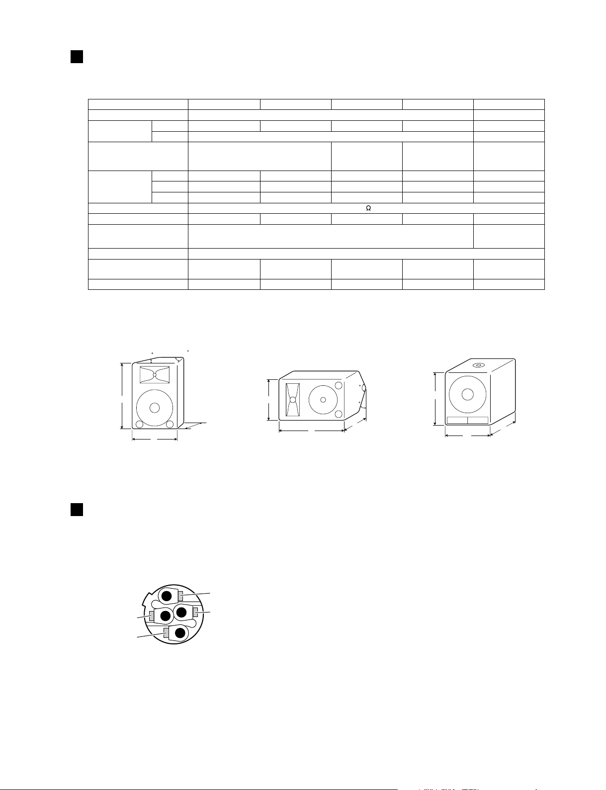
SPECIFICATIONS & DIMENSIONS
Model A10 A12 A15 A12M A15W
Type
Speaker Unit
Frequency Response
Power Capacity
Nominal Impedance
Sensitivity
Input Connectors
Socket Mount Diameter
Dimensions (WxHxD)
Weight
*
: EIA RS-426
LF
HF
NOISE*
PGM
MAX
10" cone 12" cone 15" cone 12" cone 15" cone
65 Hz-20 kHz 60 Hz-20 kHz 65 Hz-20 kHz
125 W 150 W 200 W 150 W 250 W
250 W 300 W 400 W 300 W 500 W
500 W 600 W 800 W 600 W 1000 W
96 dB SPL (1 W, 1 m) 97 dB SPL (1 W, 1 m) 98 dB SPL (1 W, 1 m) 97 dB SPL (1 W, 1 m) 97 dB SPL (1 W, 1 m)
1/4" phone jack x 1, Neutrik SPEAKON NL4MP x 1
385 mm x 542 mm x
307 mm
13.0 kg 15.5 kg 21.5 kg 15.5 kg 28.0 kg
405 mm x 582 mm x
2 way Bass reflex
1" VC, Horn-TW
323 mm
8
35 mm (1 - 3/8")
470 mmx 672 mm x
375 mm
SPEAKER SYSTEM/SUBWOOFER
A10/A12/A12M/A15/A15W
Bass reflex
-
50 Hz-200 Hz
with the internal low
pass filtering
1/4" phone jack x 2,
Neutrik SPEAKON
NL4MP x 2
582 mm x 405 mm x
323 mm
485 mm x 622 mm x
485 mm
A10/A12/A15 A12M A15W
77.5
H
102.5
120
H
D
W
W
30
D
H
W
D
Unit: mm
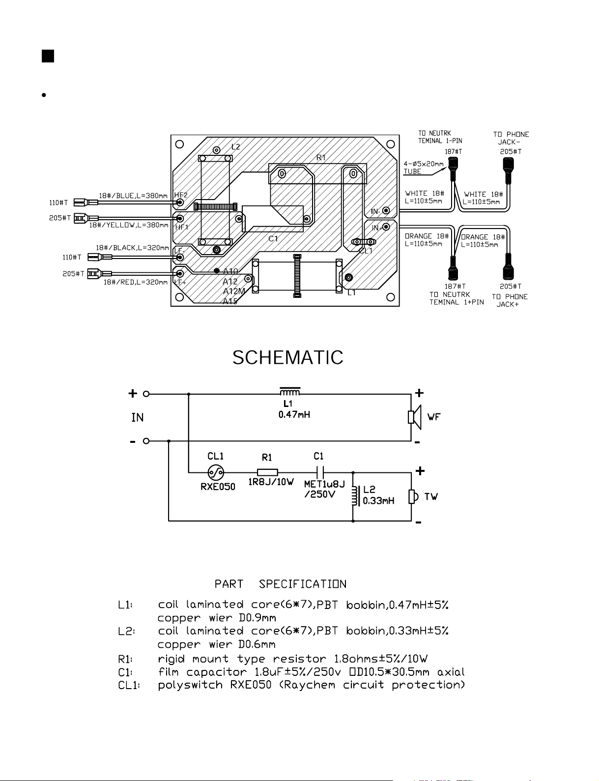
NEUTRIK NL4FC PLUG WIRING
If you will be using the Neutrik connectors for speaker input, wire the plugs as shown to the right.
Be sure to use proper speaker cable — NOT shielded instrument or line cable — for all speaker connections.
2– (NO USE)
1+ : HOT(+)
2+ (NO USE)
1– :COLD (–)
Neutrik NL4FC connector
3
SPEAKER SYSTEM/SUBWOOFER
A10/A12/A12M/A15/A15W
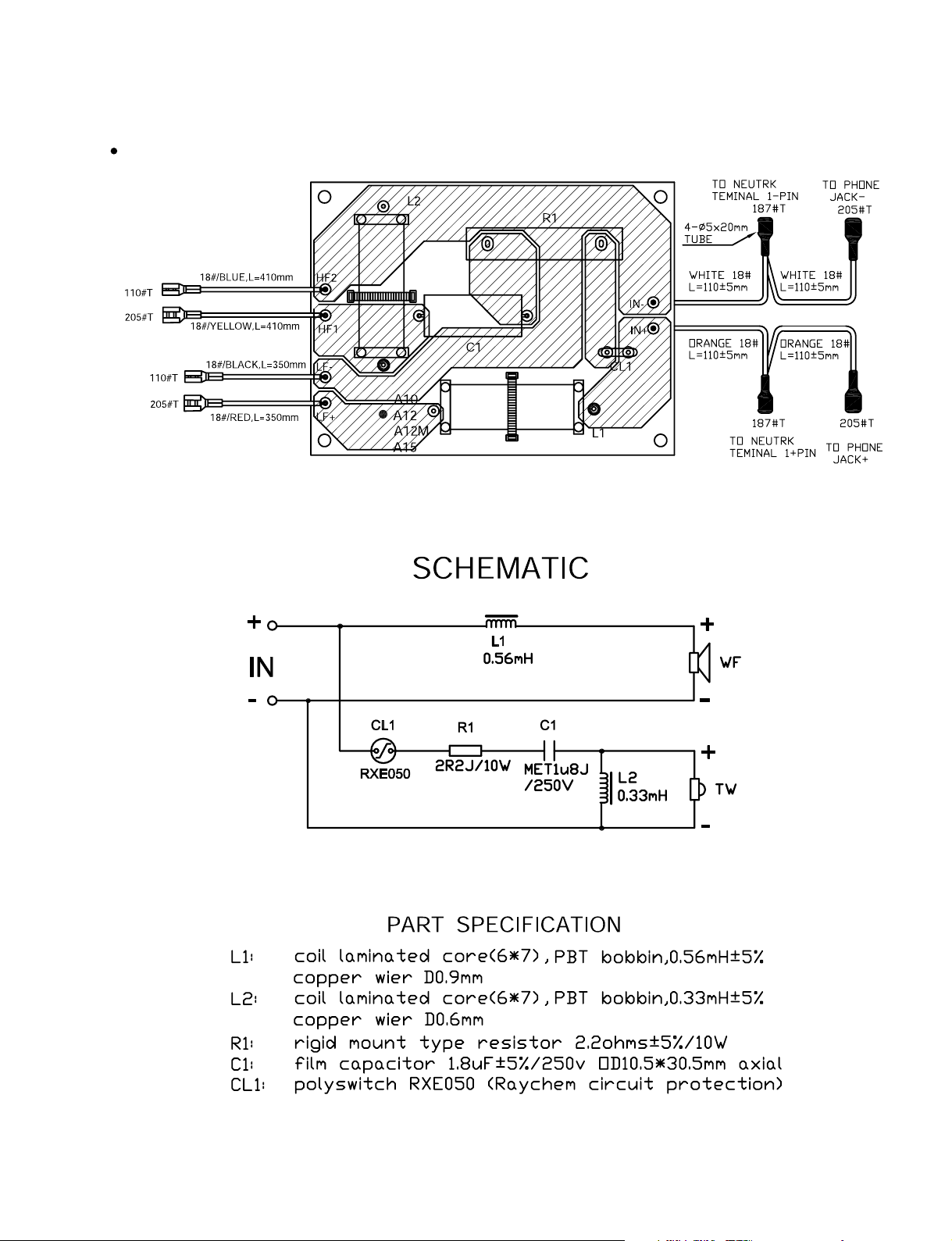
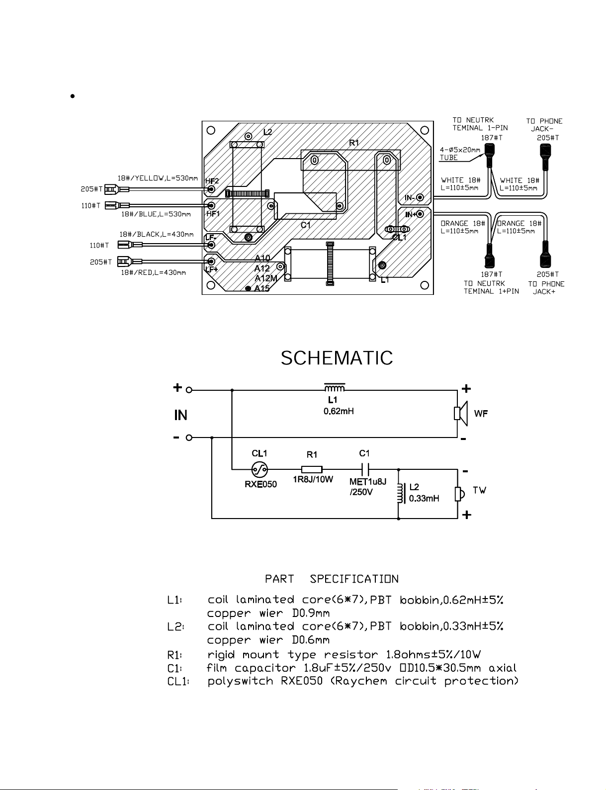
CROSSOVER
A10
4
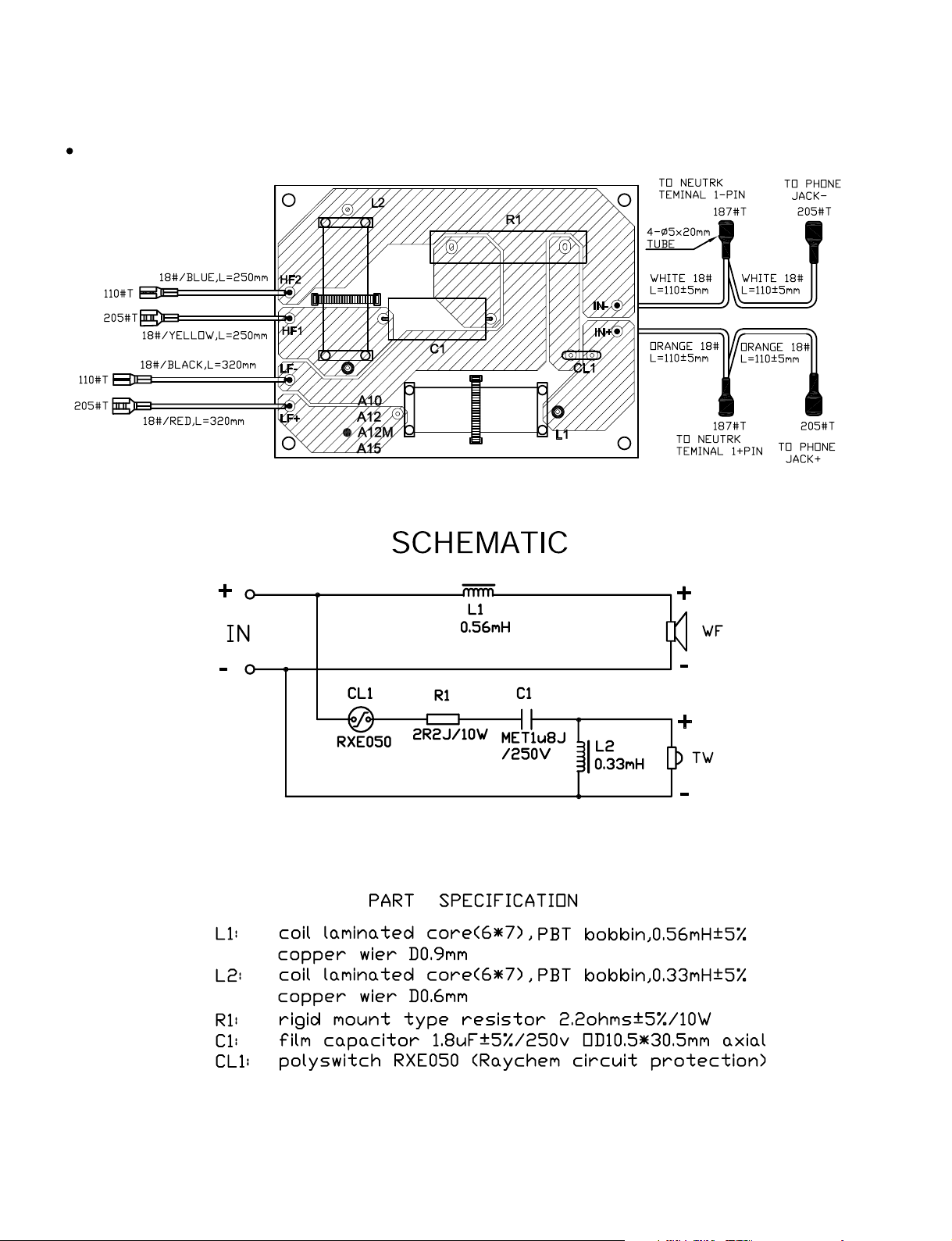
A12
SPEAKER SYSTEM/SUBWOOFER
A10/A12/A12M/A15/A15W
5
SPEAKER SYSTEM/SUBWOOFER
A10/A12/A12M/A15/A15W
A12M
6
A15
SPEAKER SYSTEM/SUBWOOFER
A10/A12/A12M/A15/A15W
Reversing
7
 Loading...