How it Works
Log In / Sign Up
Buy Points
How it Works
FAQ
Contact Us
Questions and Suggestions
Users
YAMAHA
Loading...
#
20D
73
20D’03
20D’07
20DMH
20DMHO
20ESHU2
20ESHV2
20ESHW2
20ESHY2
20M
3
20MH
20MLH
20MLHA
20MLHB
20MLHC
20MLHD
20MLHKZ
20MLHT2
20MLHU2
20MLHV2
20MLHW
20MLHW2
20MLHX
20MLHX2
20MLHY
20MLHY2
20MLHZ
20MSH
20MSHA
20MSHB
20V
25
3
210A
211MW-A0
212A
212SS
2
212SS (2013)
212SS (2016)
212X
2
212X (2013)
212X (2016)
215D
215III
225CETO ’03
225CETO ’04
225D
40
225D 2002
225DET’03
225DET’04
225F’03
225F’04
225G
12
225X
242 Limited S (2013)
250A
29
250A ’02
250A ’03
250A ’04
250AETO ’03
250B
9
250B’03
250B’04
250BETO ’03
250BETO ’04
250G
26
250GETO’07
250GETO’08
250X
25A
25B
54
25B ’02
25B’03
25B’04
25B’07
25B’08
25B’09
25B 2010
25BMH
2
25BMH’03
25C
25D
5
25J
3
25N
76
25N’03
25N’07
25NWH
25V
5
25V2
25W
25X
4
25Y
25Z
26000TE 2012
26C
276
276S
2426590
2428440
2
2440630
2
2500390
Loading...
Loading...
Nothing found
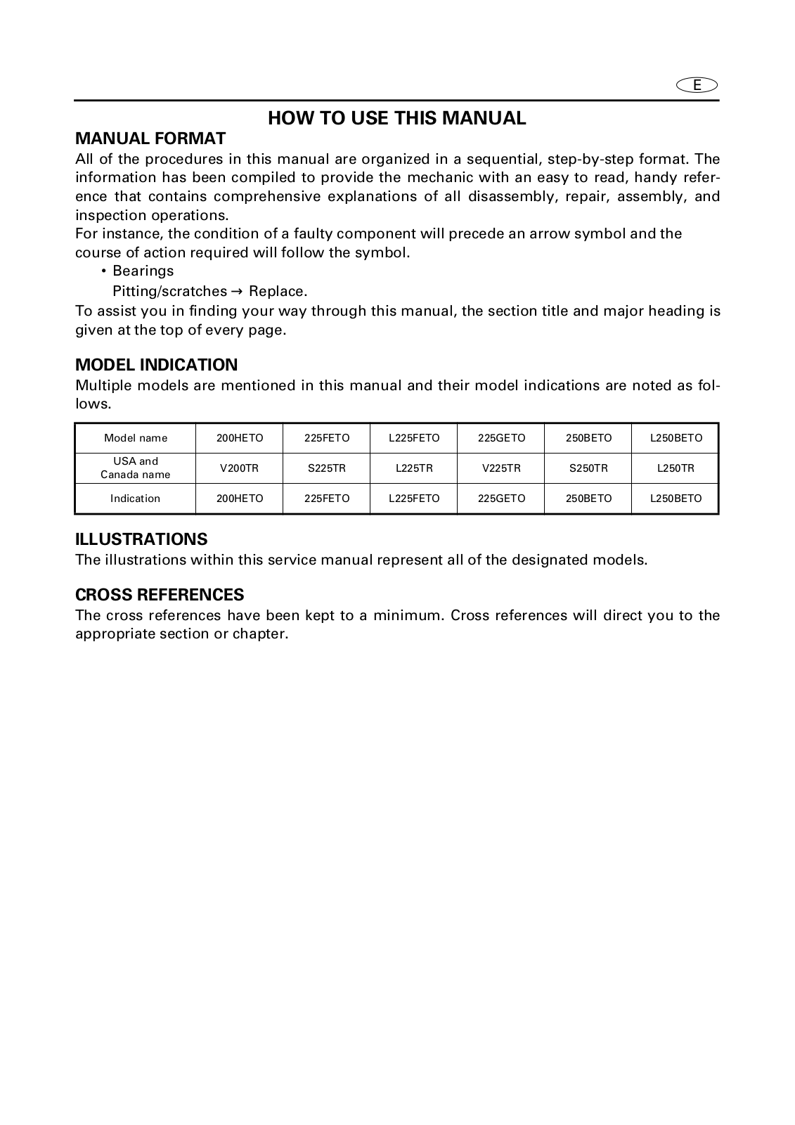
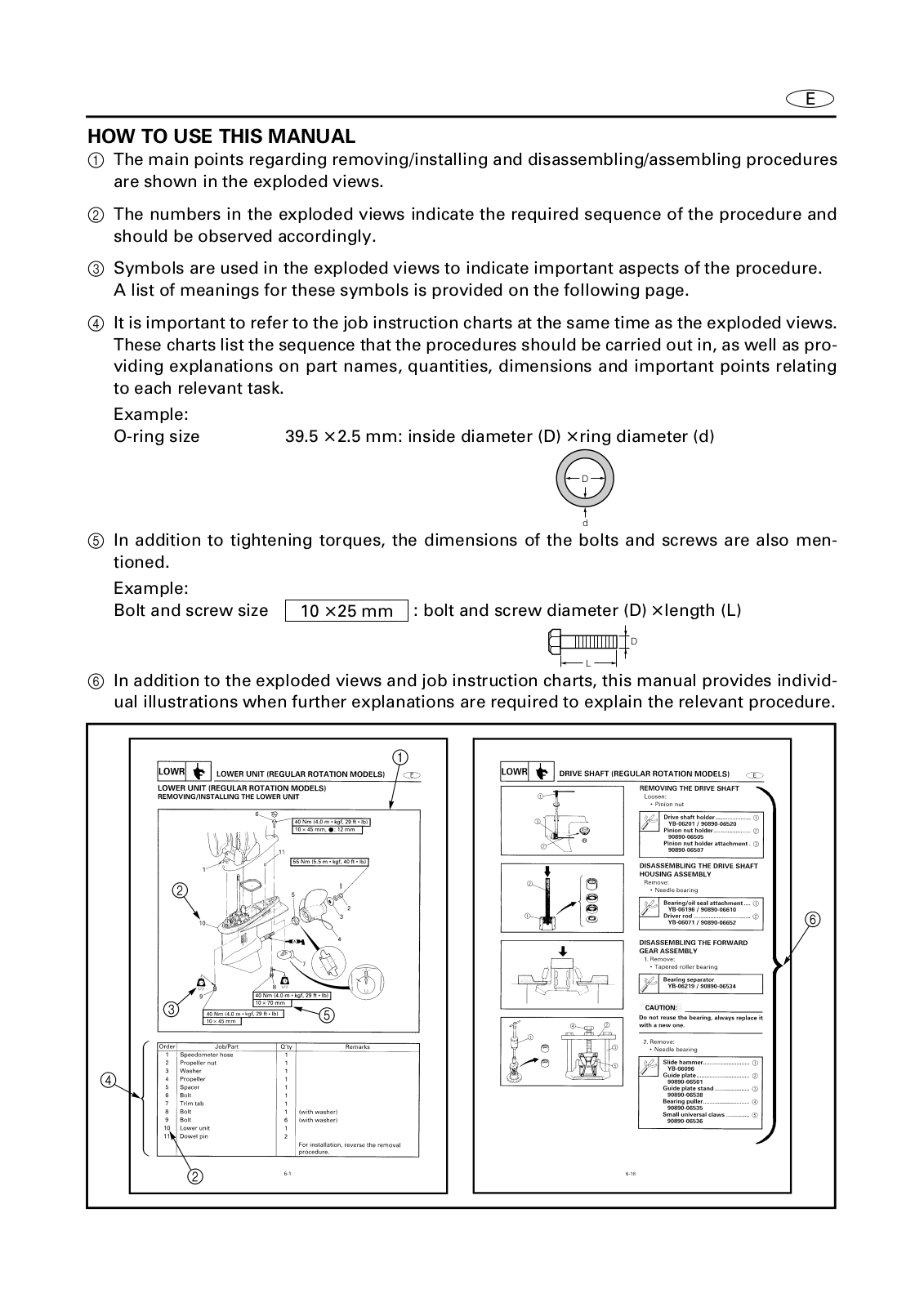
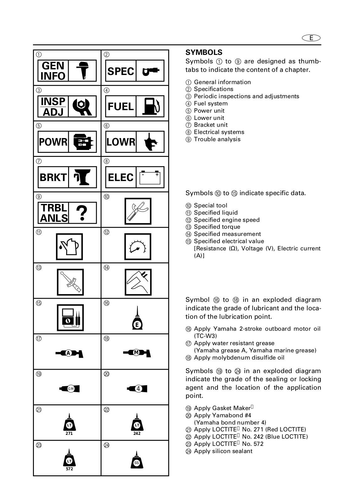
225G
PARTS CATALOGUE
367 pgs
10.65 Mb
1
User Manual
216 pgs
5.57 Mb
0
User Manual
217 pgs
6.03 Mb
0
User Manual
217 pgs
5.64 Mb
1
User Manual
216 pgs
5.61 Mb
0
User Manual [da]
219 pgs
6.3 Mb
0
User Manual [de]
218 pgs
5.95 Mb
0
User Manual [el]
220 pgs
2.46 Mb
0
User Manual [el]
218 pgs
5.81 Mb
0
User Manual [es]
220 pgs
2.54 Mb
0
User Manual [nl]
220 pgs
2.55 Mb
0
User Manual [pt]
220 pgs
2.58 Mb
0
Table of contents
Loading...
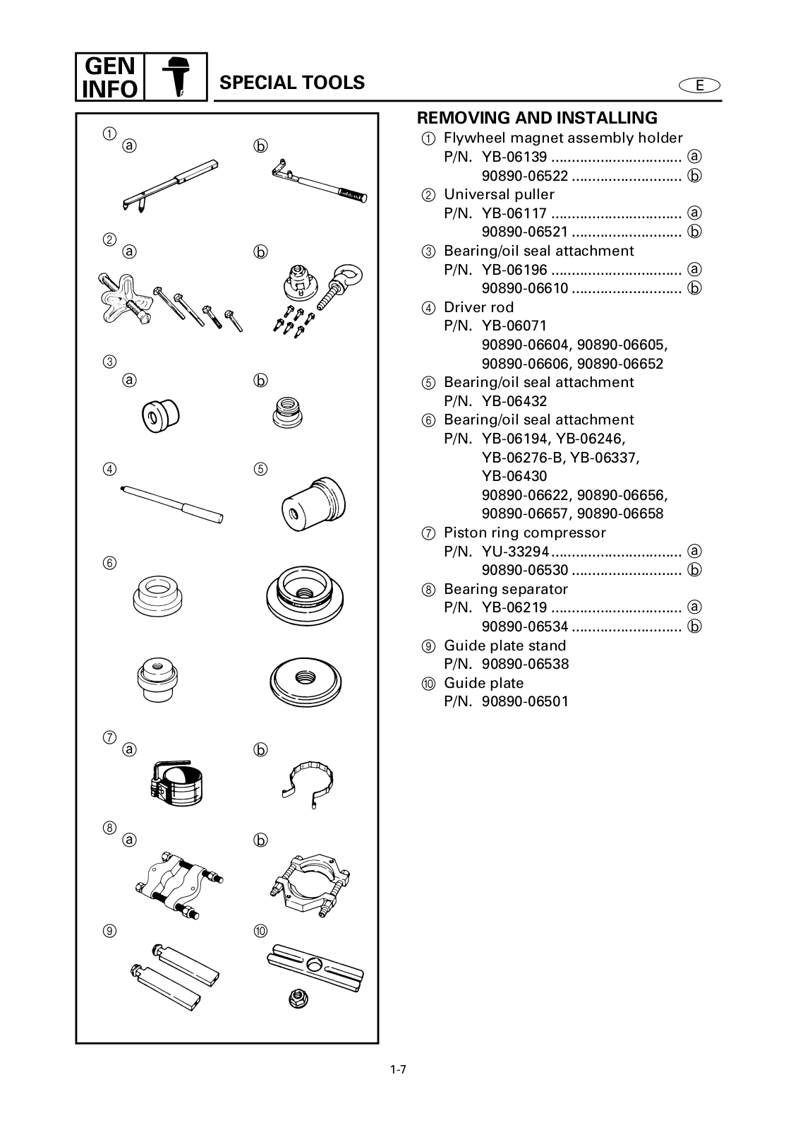
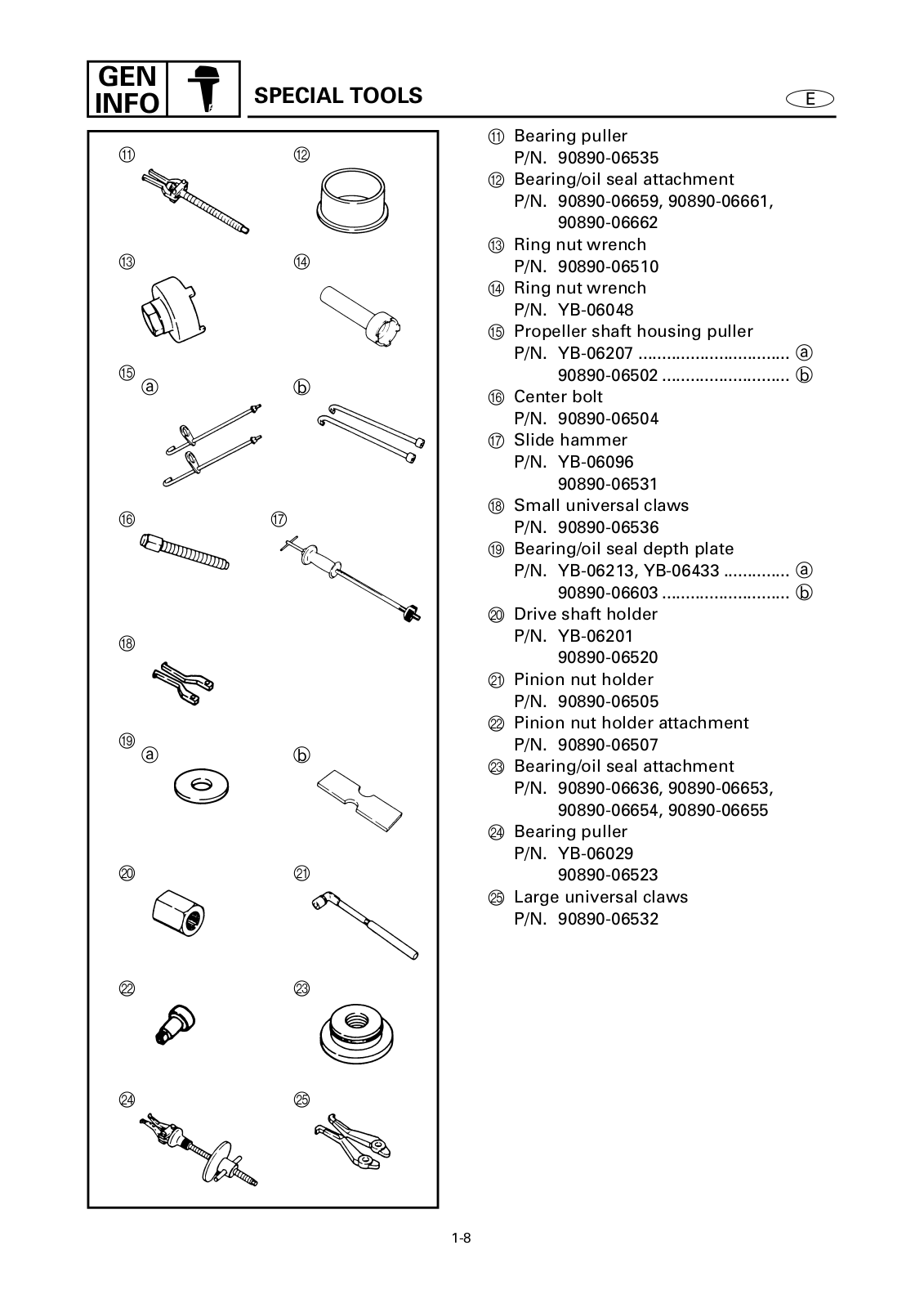
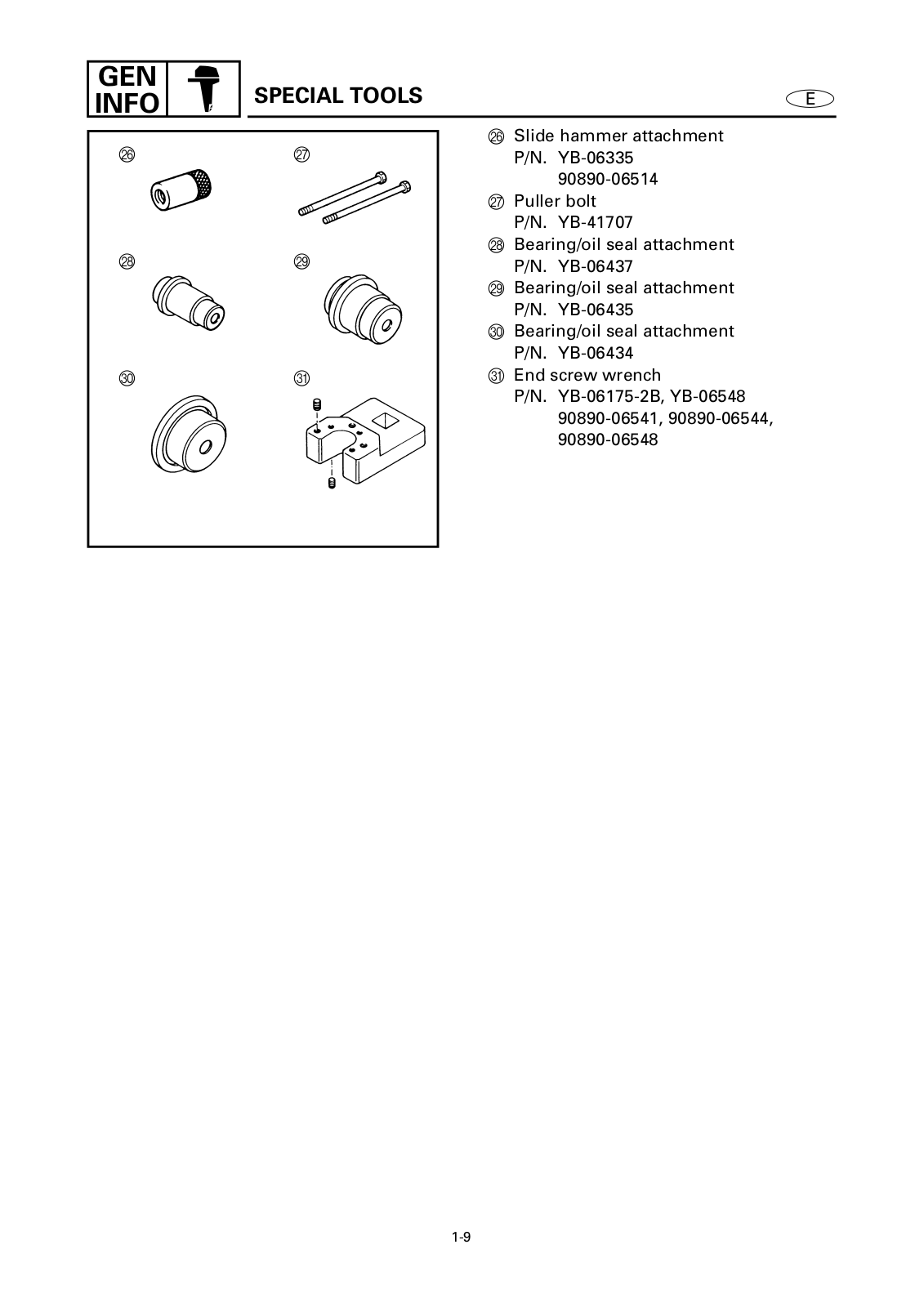
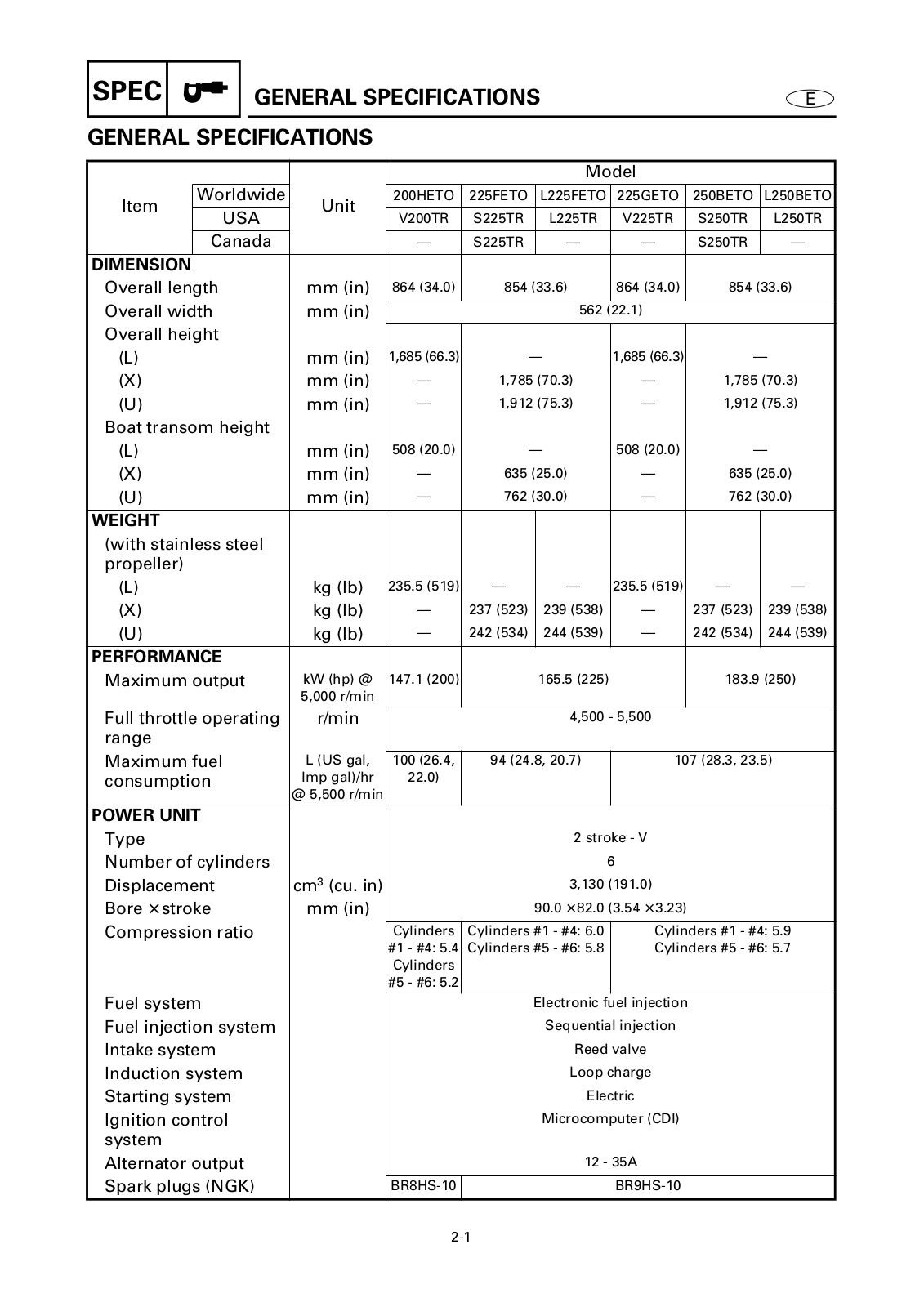
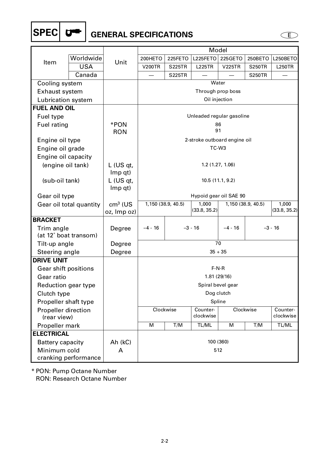
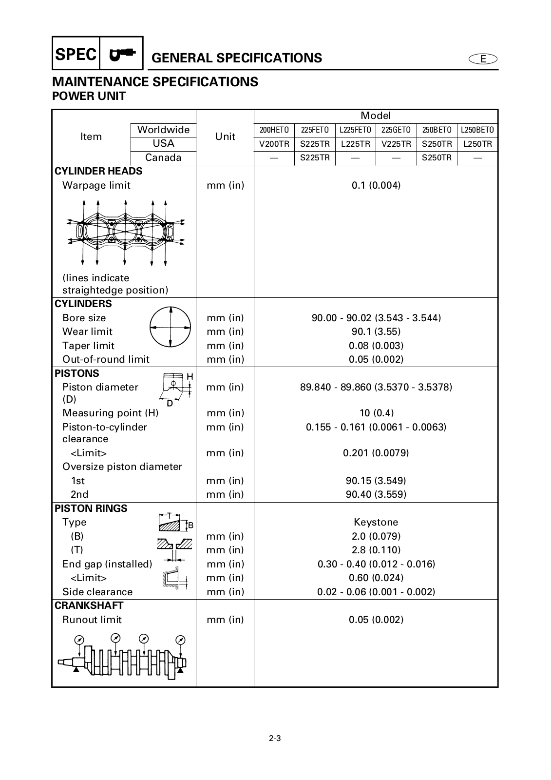
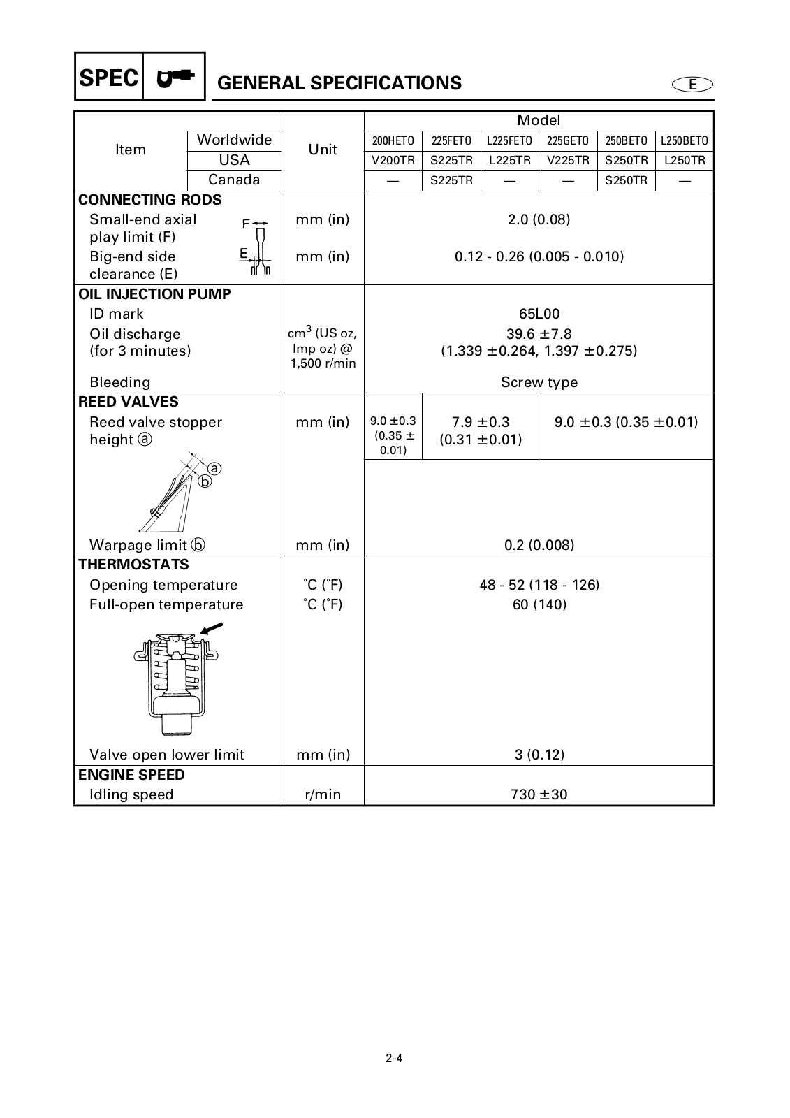
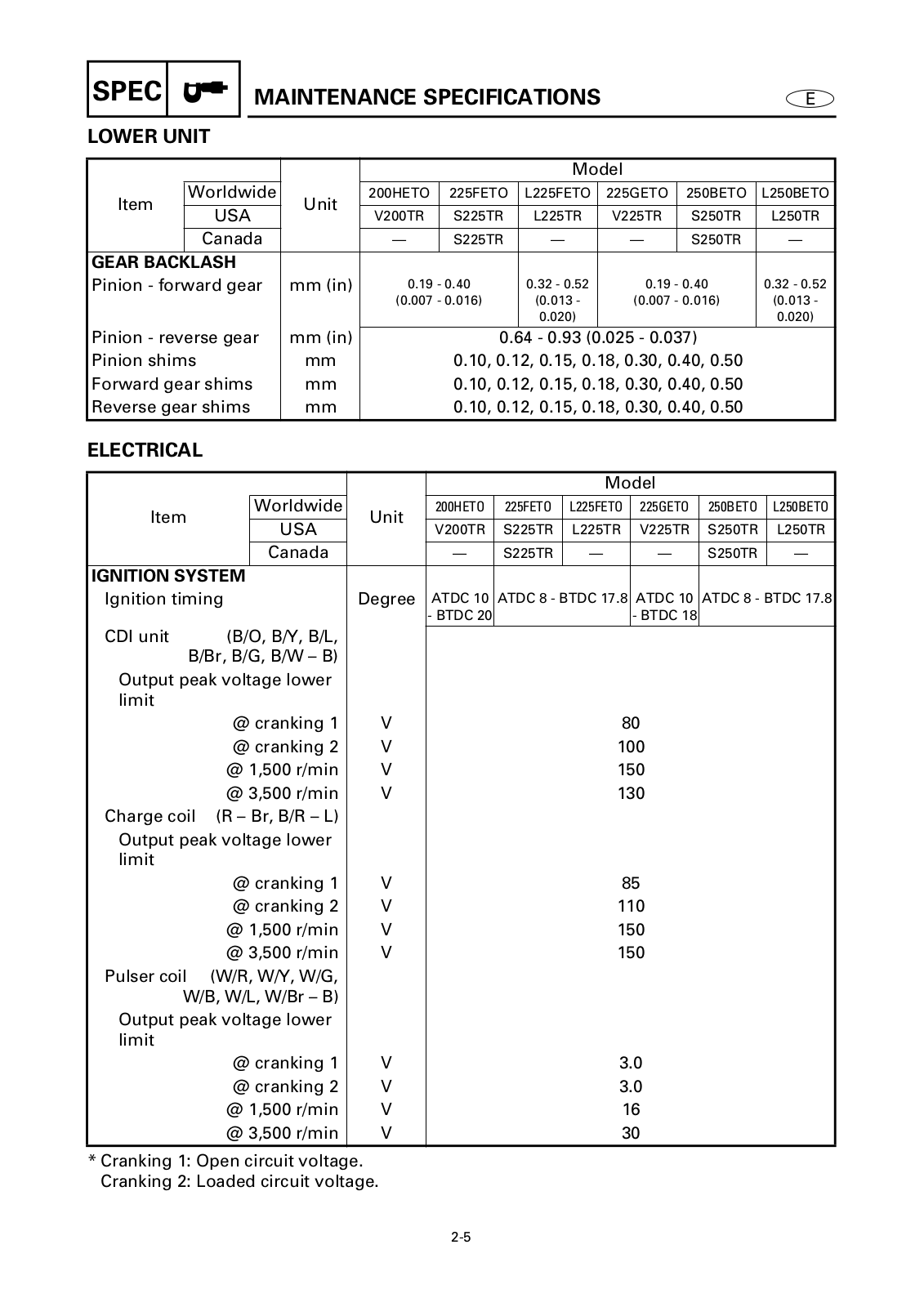
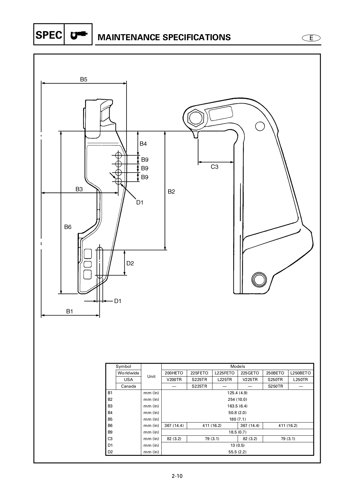
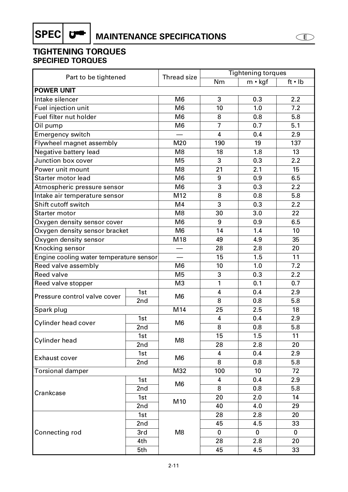
YAMAHA 225G, 250B, L250B PARTS CATALOGUE
...
YAMAHA PARTS CATALOGUE
Download
Specifications and Main Features
Frequently Asked Questions
User Manual
Download
Loading...
+
337
hidden pages
Unhide
You need points to download manuals.
1 point = 1 manual.
You can buy points or you can get point for every manual you upload.
Buy points
Upload your manuals
 Loading...