

Page 1
®
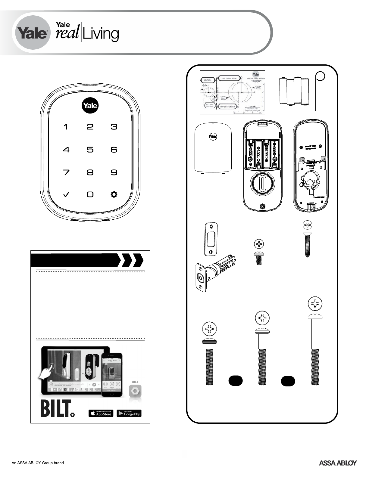
Key Free Touchscreen Deadbolt with Z-Wave Plus
Installation and Programming Instructions
Yale Real Living
®
YRD156
Before you begin
DOWNLOAD
THE BILT APP
for step-by-step installation
instructions & to register
your product
FAILURE TO FOLLOW THESE INSTRUCTIONS COULD RESULT IN DAMAGE TO
#8-32 x 5/16"
Machine screws
OR
x2 Gold
M6x36mm
PPHMS
(1-3/8" )
THE PRODUCT AND VOID THE FACTORY WARRANTY
(Standard 1-3/4" - 2" )
x3
x2 Black
M6x44mm
PPHMS
x4
#7 wood & #8-32
machine x 20mm
Combination screws
OR
x2 Silver
M6x55mm
PPHMS
(2-1/4" )
1
P/N - - Rev AAYRD 156-INST FUL
Page 2
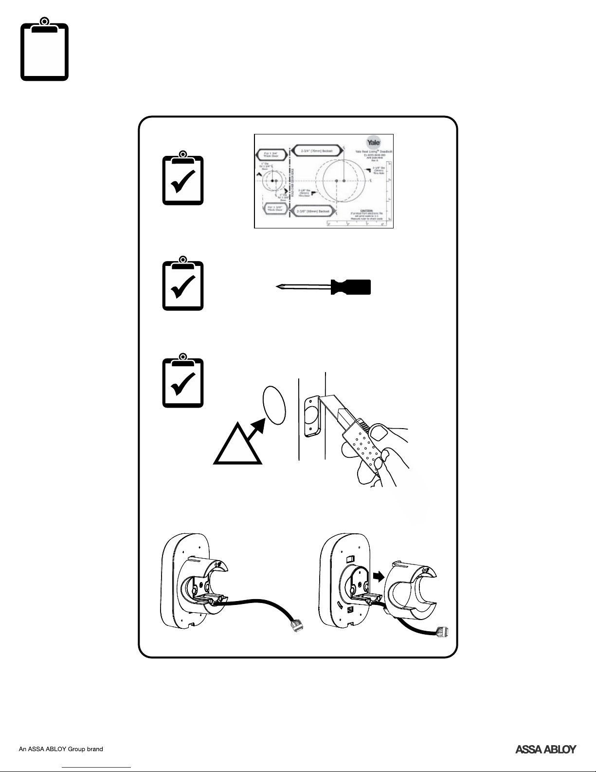
Preparing Door and Touchscreen Escutcheon
Cup must be removed from
escutcheon if bore hole is
less than 2-1/8".
2-1/8" Application
!
<2-1/8" Application
2
P/N - - Rev AAYRD 156-INST FUL
Page 3
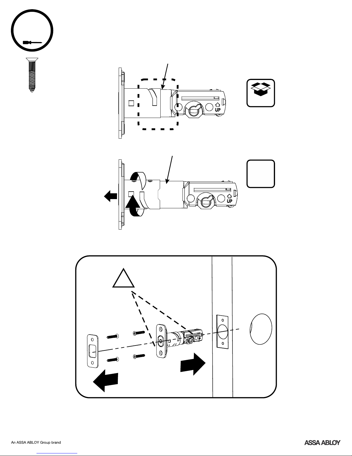
1
Installing Latch & Strike Plate
2-3/8" position
x4
3
2- /
8
2-3/4" position
3
2- /
4
Rotate
Bolt must be in retracted
(unlocked) position. UP
!
arrow must be facing
upwards.
2- /
default
O
optional
3
8
3
P/N - - Rev AAYRD 156-INST FUL
Page 4
2
Installing Touchscreen Escutcheon
!
If bore hole is less
than 2-1/8", remove
cup by gently
compressing two
tabs while pulling.
Outside of Door
!
Ensure cable is
routed under the
deadbolt.
4
P/N - - Rev AAYRD 156-INST FUL
Page 5
3
x2
Installing Interior Mounting Plate
!
Choose
through bolt
appropriate for
your door
thickness.
5
P/N - - Rev AAYRD 156-INST FUL
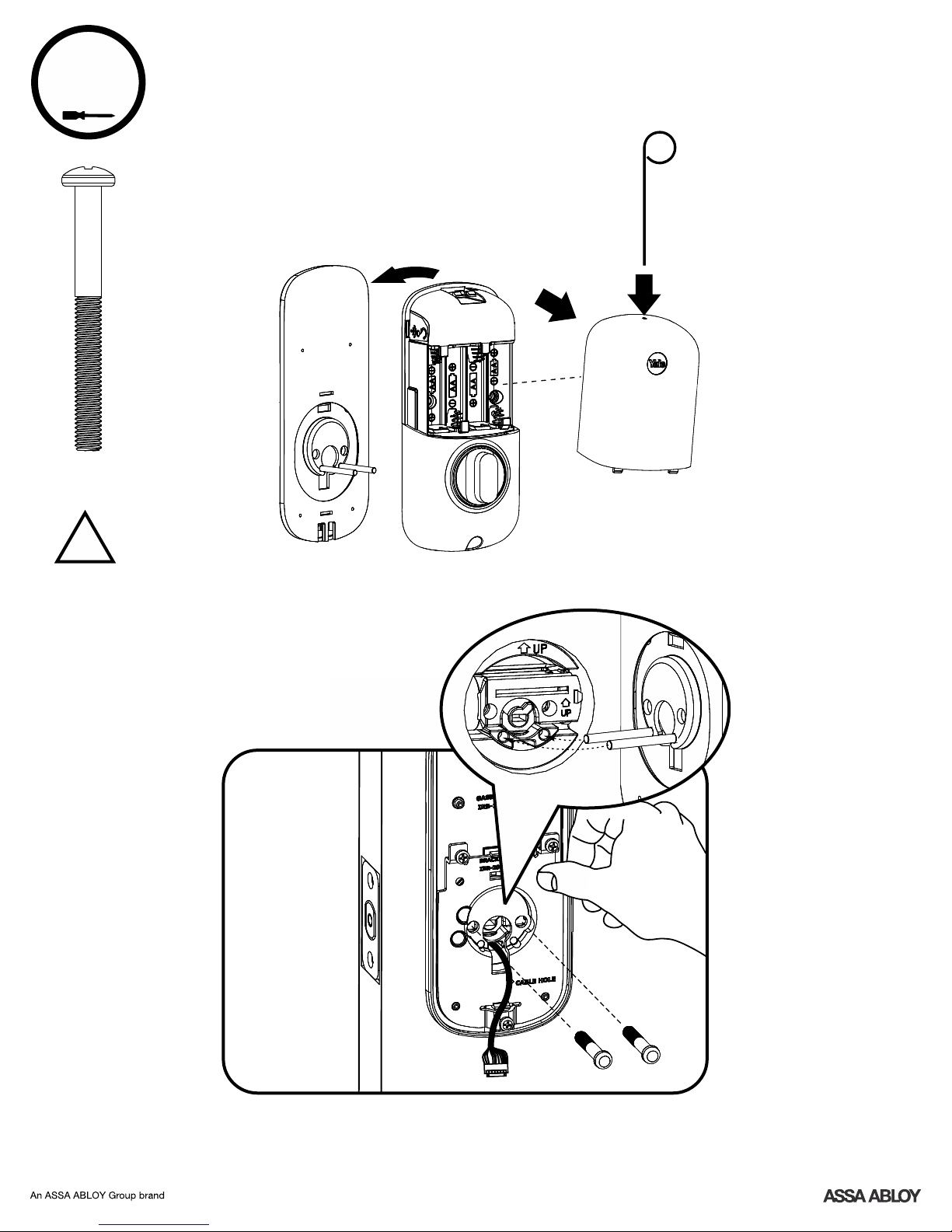
Page 6
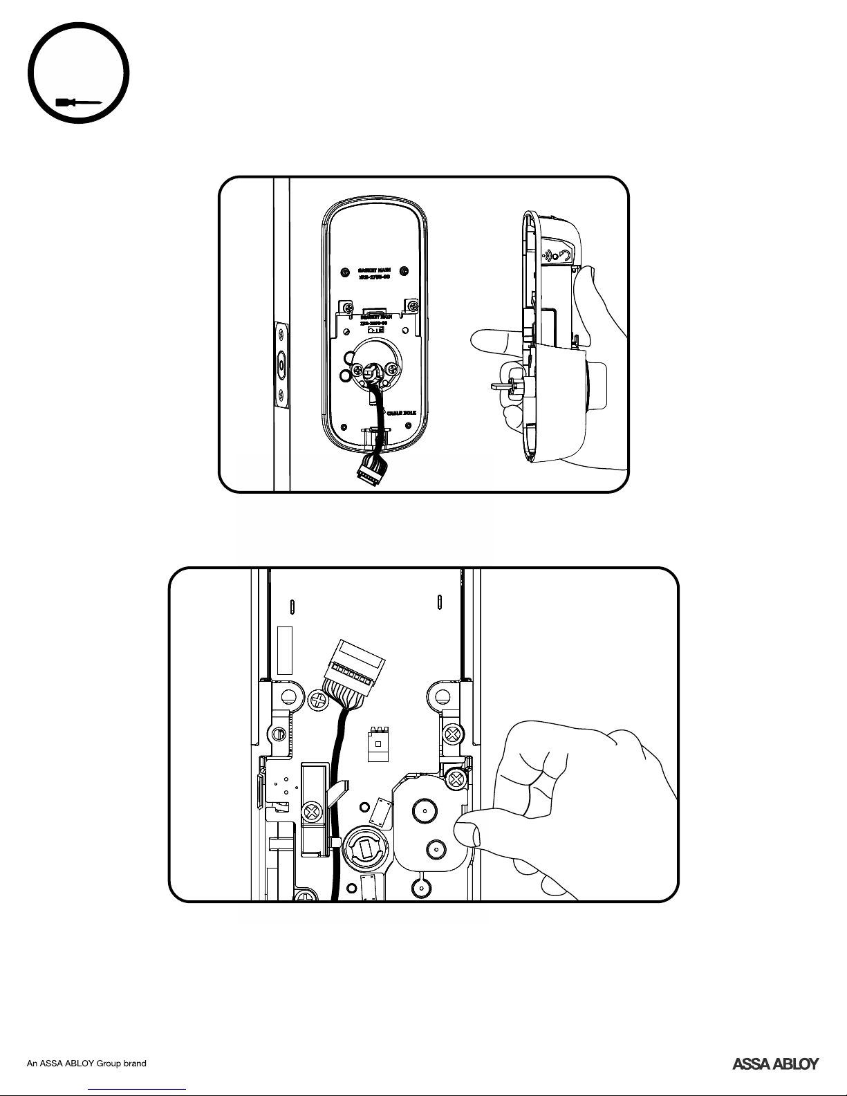
4
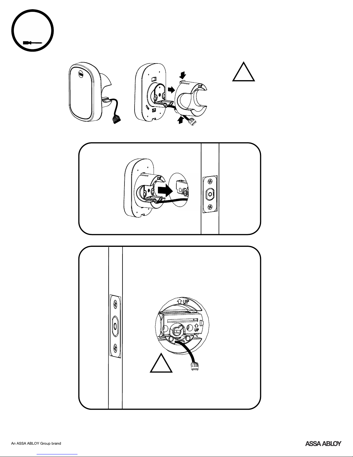
Attaching the Cable Assembly
6
P/N - - Rev AAYRD 156-INST FUL
Page 7
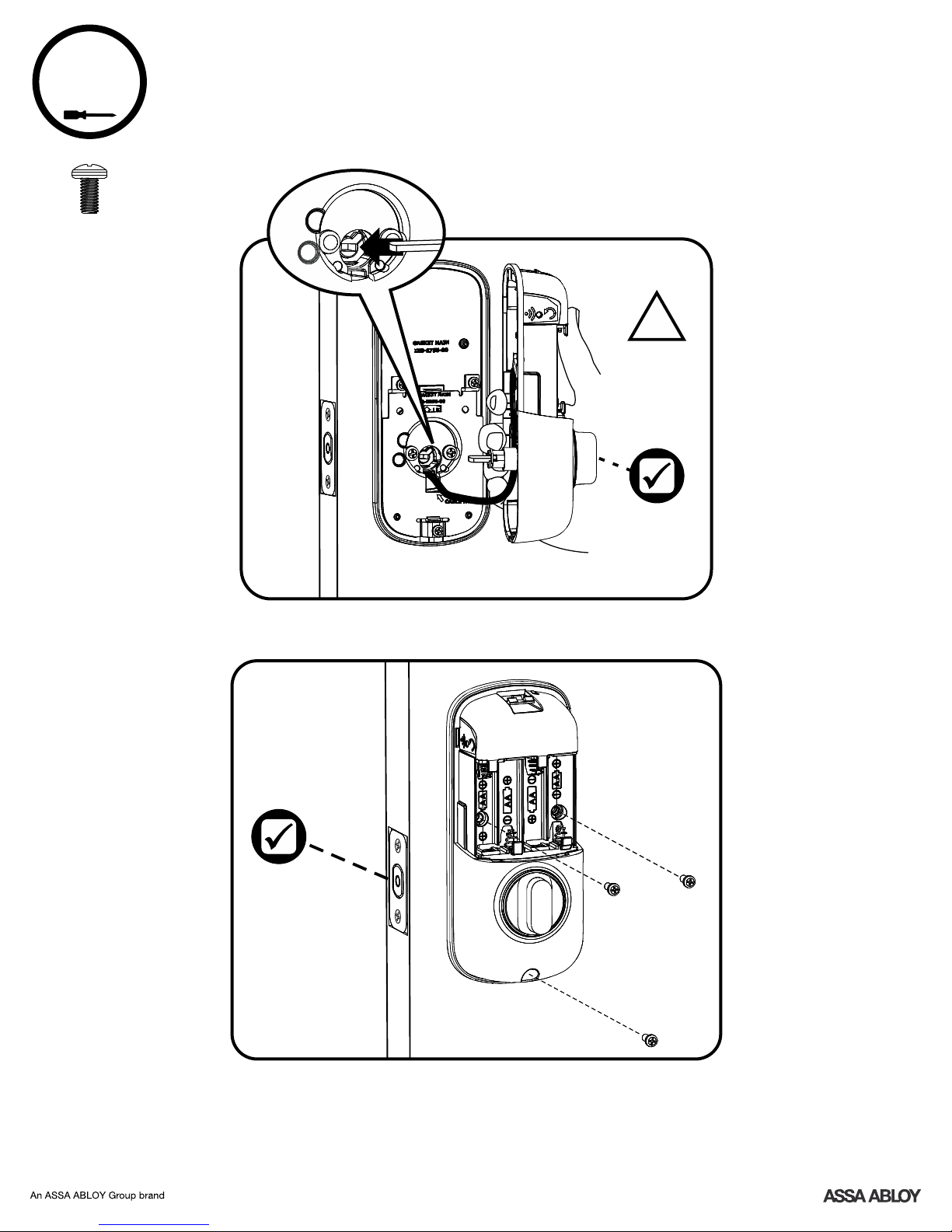
5
x3
Installing Interior Escutcheon
!
Thumbturn
should be in
vertical
position.
7
P/N - - Rev AAYRD 156-INST FUL
Page 8
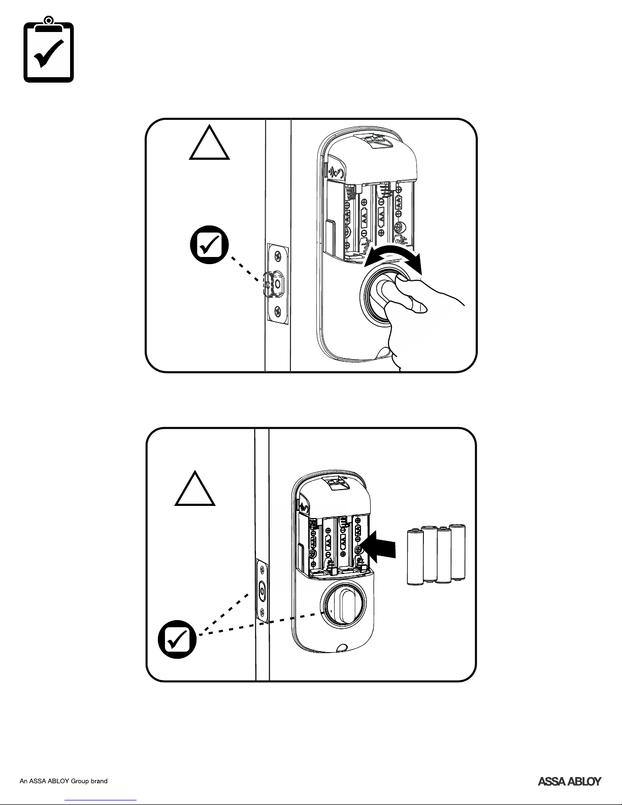
Testing Operation
!
Deadbolt should
extend and retract
smoothly. If not, go
back to step 2.
!
Bolt must be in
retracted
(unlocked)
position before
installing AA
batteries.
8
P/N - - Rev AAYRD 156-INST FUL
Page 9

Initial Programming
Press .
Enter new Master PIN
code (4-8 digits).
Press to complete.
!
Lock will not operate
until gear is pressed
and Master PIN code
is set.
After entering the Master PIN
code, press any key to complete
handing.
9
P/N - - Rev AAYRD 156-INST FUL
Page 10

6
Installing Cover
Congratulations, you've installed the Yale Real Living
YRD156 Key Free Touchscreen Deadbolt with Z-Wave Plus!
Continue with Programming Instructions to customize your product.
®
10
P/N - - Rev AAYRD 156-INST FUL
Page 11

Programming Instructions
Touchscreen Wake-Up
All Code Lockout Mode
Rapidly beeps 5 times
Low Battery Warning
Flashes RED
Failsafe 9 Volt
Battery Connection
(Use Alkaline battery)
Master Code must be created before any further programming.PIN
Max User Codes = 250 in network
Warning: Changes or modifications to this device, not expressly approved by
ASSA ABLOY Residential Group could void the user's authority to operate the equipment.
11
P/N - - Rev AAYRD 156-INST FUL
Page 12

1
Changing Master CodePIN
Press
Enter Master codePIN
Press
Press
Press
Enter 4-8
digit Master
Code.PIN
Press
12
P/N - - Rev AAYRD 156-INST FUL
Page 13

2
Creating User CodesPIN
Master code must be created first.PIN
Max User Codes = 250 in network
Press
Enter Master codePIN
Press
Press
Press
Press
Press
Enter 4-8 digit codePIN
Press
13
P/N - - Rev AAYRD 156-INST FUL
Page 14

3
Unlocking Door with CodePIN
Press
Code Chart
User Name
Enter PIN
Press
"Unlock"
Duplicate if necessary
PIN Code Management - Up to 250 Users (in network)
PIN Code
14
P/N - - Rev AAYRD 156-INST FUL
Page 15

Resetting Lock to Factory Default
When lock is reset to factory defaults all
user codes (including the Master PIN
code*) are deleted and all programming
features are reset to original default
settings (see "Factory Default Settings").
1. Remove the battery cover.
2. Remove the batteries.
3. While pressing the reset button
(minimum of 3 seconds) reinstall
batteries. Release reset button.
4. Replace battery cover.
Upon reset, Master Code creation is the
only option available and must be
performed prior to any other
programming of the lock.
: After setting the Master Code,NOTE
press any key to complete handing of
the lock.
Adding Lock To Z-Wave Plus Network
Your network controller first needs to be in
inclusion or exclusion mode for the lock to
be added or removed from network.
Once you put the controller in the
inclusion or exclusion mode, the lock can
be added or removed in the Z-Wave Plus
Plus network by pressing the button .
To add lock using the
1. Remove the battery cover.
2. Press button and hold until unit beeps
two (2) times.
3. Release button and network joining
automatically begins.
4. Replace battery cover.
To remove lock using the button option:
1. Remove the battery cover.
2. Press button and hold until unit beeps
five (5) times.
3. Release button and network removal
automatically begins.
4. Replace battery cover.
button option:
15
P/N - - Rev AAYRD 156-INST FUL
Page 16

Definitions
All Code Lockout Mode: This feature is enabled by the Master code. When enabled, it restricts all user (except Master) codePIN
access. When attempting to enter a code while the unit is in Lockout, the lock rapidly beeps 5 times.
Audio Mode: Disable (3)Choosing in Audio mode shuts off the code confirmation tone play-back for use in quiet areas. Audio
mode is enabled or disabled through feature programming by the Master code.
Automatic Re-lock Time: After a successful code entry or manual unlock with the key, the lock will automatically re-lock after
each unlock in an effort to keep your home secure. This feature is optional, and can be turned off. In the ON mode, the lock will
automatically re-lock after thirty (30) seconds.
Low Battery: When battery power is low, the Low Battery Warning Indicator flashes . If battery power is completely lost, useRED
the 9Volt battery override. To use the 9V battery override apply 9V battery, in either direction, to terminals below the touchscreen
for backup power option. Wake up the lock and enter your pin code to unlock the door.
Master Code: It must be created prior toPIN The Master code is used for programming and for feature settings.PIN
programming the lock. The Master code will also operate (unlock/lock) the lock.
Network Setting: This setting is available through the wireless button on the interior escutcheon and allows the lock to connect
with a network controller.
One Touch Locking: When the latch is retracted, activating the touchscreen will extend the latch (during Automatic Re-lock
duration or when Automatic Re-lock is disabled).
Shutdown Time: The unit will shutdown (flashing touchscreen) for sixty (60) seconds and not allow operation after the wrong
code entry limit has been met.
Tamper Alert: Audible alarm sounds if attempting to forcibly remove outside lock from door.
User Code:PIN The User code operates the lock. Maximum number of user codes is 250 in network.
Wrong Code Entry Limit: After five (5) unsuccessful attempts at entering a valid code, the unit will shut down and not allowPIN
operation for sixty (60) seconds.
16
P/N - - Rev AAYRD 156-INST FUL
Page 17

Feature Programming Through Menu Mode
Using Master code*PIN
ake the lock by pressing the .
1. W
2. Enter the 4-8 digit Master PIN code followed by the
3. Enter digit corr
esponding to the function to be performed followed by the key.
key.
Master Code SettingPIN
User Code RegistrationPIN
Advanced Lock Settings
Default settings
in bold.
Audio Mode
M
Register
Delete
Automatic Re-lock
One Touch Locking
Handing the Lock
Enable
U
U
Disable
30 sec
60 sec
2 min
3 min
Enable
Disable
Preforms automatic
handing of the lock
Continue
Complete
All Code Lockout Mode
Factory Settings
Settings
Master CodePIN
Automatic Re-lock
One Touch Locking
Audio Enabled
Automatic Re-lock Time
Wrong Code Entry Limit
Shutdown Time 60 Seconds
*The Master code must be registered prior to any other programming of the lock.PIN
Disable
Factory Setting
Registration
For quiet areas, select Disable (3)
in Audio Mode.
Enable
Disable
required*
Disabled
Enabled
30 Seconds
5 Times
17
P/N - - Rev AAYRD 156-INST FUL
Page 18

Programming Troubleshooting
Symptom
Suggested Action
18
P/N - - Rev AAYRD 156-INST FUL
Page 19

Warning: Changes or modifications to this device, not expressly approved by ASSA
ABLOY Residential Group could void the user's authority to operate the equipment.
!
FCC:
Contain FCC ID: 2ABFG- YRIZW2USTS1
Model: YRD156-ZW-619,605,0BP
This equipment has been tested and found to comply
with the limits for a Class B digital device, pursuant
to Part 15 of the Rules. These limits areFCC
designed to provide reasonable protection against
harmful interference in a residential installation. This
equipment generates, uses, and can radiate radio
frequency energy and, if not installed and used in
accordance with the instructions, may cause harmful
interference to radio communications. However, there
is no guarantee that interference will not occur in a
particular installation. If this equipment does cause
harmful Interference to radio or television reception,
which can be determined by turning the equipment
off and on, the user is encouraged to try to correct
the interference by one or more of the following
measures:
Reorient or relocate the receiving antenna.
Increase the separation between the equipment
and receiver.
Connect the equipment into an outlet on a circuit
different from that to which the receiver is
connected.
Consult the dealer or an experienced radio/TV
technician for help.
THIS DEVICE COMPLIES WITH PART OF THE FCC15
RULES OPERATION IS SUBJECT TO THE FOLLOWING.
TWO CONDITIONS.
(1) THIS DEVICE MAY NOT CAUSE HARMFUL
INTERFERENCE AND THIS DEVICE MUST ACCEPT, (2)
ANY INTERFERENCE RECEIVED INCLUDING,
INTERFERENCE THAT MAY CAUSE UNDESIRED
OPERATION.
Industry Canada:
Contain 11626A- YRIZW2USTS1
Model: YRD156-ZW-619,605,0BP
Section 7.1.2 of -RSS GEN Under Industry Canada
regulations, this radio transmitter may only operate
using an antenna of a type and maximum (or lesser)
gain approved for the transmitter by Industry Canada.
To reduce potential radio interference to other users,
the antenna type and its gain should be so chosen
that the equivalent isotropically radiated power
(e.i.r.p.) is not more than that necessary for
successful communication.
En vertu des règlements d'Industrie Canada, cet
émetteur radio ne peut fonctionner avec une antenne
d'un type et un maximum (ou moins) approuvés pour
gagner de l'émetteur par Industrie Canada. Pour
réduire le risque d'interférence aux autres
utilisateurs, le type d'antenne et son gain doivent
être choisies de façon que la puissance isotrope
rayonnée équivalente ( ) ne dépasse pas ce quiPIRE
est nécessaire pour une communication réussie.
Section 7.1.3 of -RSS GEN This Device complies with
Industry Canada License-exempt standard(s).RSS
Operation is subject to the following two conditions:
1) this device may not cause interference, and 2) this
device must accept any interference, including
interference that may cause undesired operation of
the device.
Cet appareil est conforme avec Industrie Canada RSS
standard exemptes de licence(s). Son fonctionnement
est soumis aux deux conditions suivantes: 1) ce
dispositif ne peut causer des interférences, et 2) cet
appareil doit accepter toute interférence, y compris
les interférences qui peuvent causer un mauvais
fonctionnement du dispositif.
This radio transmitter 6982A- 0 hasYRHCPZW FM
been approved by Industry Canada to operate with
the antenna types listed below with the maximum
permissible gain indicated. Antenna types not
included in this list, having a gain greater than the
maximum gain indicated for that type, are strictly
prohibited for use with this device.
Le présent émetteur radio 6982A- 0 aYRHCPZW FM
été approuvé par Industrie Canada pour fonctionner
avec les types d'antenne énumérés ci-dessous et
ayant un gain admissible maximal. Les types
d'antenne non inclus dans cette liste, et dont le gain
est supérieur au gain maximal indiqué, sont
strictement interdits pour l'exploitation de l'émetteur.
CAN ICES NMB-3B/ -3B
19
P/N - - Rev AAYRD 156-INST FUL
Page 20

NOTE TO INSTALLER AND CONSUMER
While Yale has included several features to prevent lockout
®
(9-Volt battery jumper, low battery warnings), it is still possible
for a lockout situation to occur. Because this product does not
have a mechanical override (a key), Yale recommends to use
®
this product in an environment where there are additional
entry points into the dwelling.
Product Support Tel 1-855-213-5841 • www.yalehome.com
Yale and Yale Real Living are registered trademarks of ASSA ABLOY Residential Group. Other products' brand®®
names may be trademarks or registered trademarks of their respective owners and are mentioned for reference
purposes only. © Copyright 2018. All rights reserved. Reproduction in whole or in part without the express written
permission of ASSA ABLOY Residential Group is prohibited.
20
P/N - - Rev AAYRD 156-INST FUL
Page 21

Yale Locks
Z-Wave Plus System Integrators Guide
Yale YRD15 6
1
Page 22

Contents
Yale Z-Wave Plus Product Info ...................................................................................................................... 3
Supported Command Classes .................................................................................................................. 3
Association Table .................................................................................................................................... 3
Notifications Table .................................................................................................................................. 4
Configurable Parameters ......................................................................................................................... 6
2
Page 23

Yale Z-Wave Plus Product Info
Group ID
Maximum Nodes
Description
Commands
1 1 Lifeline
Command_Class_Battery, Battery_Report ;
Command_Class_Notification, Notification_Report;
Command_Class_Configuration, Configuration_Report;
Command_Class_Device_reset_locally,
Device_Reset_locally_notification
Manufacturer ID: Assa Abloy (0x0129)
Z-Wave Device Type: Door Lock Keypad
Z-Wave Role Type: Listening Sleeping Slave (LSS)
Product ID: 0x0508
Product Type ID:
0x803A – YRD156-ZW2 (Touchscreen Deadbolt)
Supported Command Classes
Command Class Z-Wave Plus Info
Command Class Manufacturer Specific
Command Class Security
Command Class Device Reset Locally
Command Class Power Level
Command Class Version
Command Class Battery*
Command Class Door Lock*
Command Class Door Lock Logging*
Command Class Schedule Entry Lock*
Command Class User Code*
Command Class Time Parameters*
Command Class Time*
Command Class Association*
Command Class Association Group Info*
Command Class Notification*
Command Class Configuration*
Command Class Firmware Update Md*
* Command Class Requires Security
Association Table
3
Page 24

Notifications Table
Alarm Reports
Alarm
type
Alarm Level
Description
Master Code
changed.
0x70
0x00
Master code was changed at keypad
0xFB
Master code was changed over RF
User added
0x(01-max
users)
User added. Alarm level = user slot number
User deleted
0x21
0x(01-max
users)
User was deleted. Alarm level = user slot number
Tamper Alarm
0xA1
0x01
keypad attempts exceed code entry limit
0x02
front escutcheon removed from main
RF Operate Unlock
0x19
0x01
by RF module
Manual Unlock
0x16
0x01
By key cylinder or
inside thumb turn
Keypad Unlock
0x13
0x(01-max
users)
Where Alarm level represents user slot number (0xFB =
Master Code)
Manual Lock
0x15
0x01
by key cylinder or inside thumb-turn
0x02
by touch function (lock and leave)
0x03
By inside button
RF Operate Lock
0x18
0x01
by RF module
Keypad Lock
0x12
0x (01 – max
users)
Where Alarm level represents user slot number
Non Access
0x26
0x(01-max
users)
A Non Access Code was entered at the lock.
Where alarm level represents user slot number
Deadbolt Jammed
0x09
0x01
Deadbolt jammed
while locking
0x02
Deadbolt jammed
while unlocking
Low Battery
Alarms**
0xA9
0x (Current %)
Too Low to operate (Starting at 3.8V)
0xA8
0x (Current %)
Critical Battery Level (Starting at 3.9V)
0xA7
0x (Current %)
Low Battery
(Starting at 4.2V)
Auto Lock Operate
Locked
0x1B
0x01
Auto re-lock cycle complete, locked.
4
Page 25

Duplicate Pin-code
error
0x71
0x (01-max
users)
Where Alarm level represents user slot number
Alarm generated in response to add user RF cmd.
This alarm is not generated when attempting to add
duplicate pin at the keypad. The lock simply denies it
and plays the “Denied”. Trying to duplicate the
master code will result in a 0x71 0x00 alarm report.
RF Module Power
Cycled
0x82
0x00
Power to RFM was restored, sent by RF module. The
lock doesn’t send any alarm to the RF module when
power is cycled.
Disabled user
entered at keypad
0x83
0x(01-max
users)
A disabled user pin code was entered at the keypad
Valid user but
outside of schedule
0x84
0x(01-max
users)
A valid user can be both a normal user and a Non-
Access user. If a non-access user is out of schedule this
alarm will be sent instead of the non-access alarm.
Daily Repeating
Schedule
Set/Erased
0x60
0x(01-max
users)
Schedule(s) has been set/erased for specified user ID
Daily Repeating
Schedule
Enabled/Disabled
0x61
0x(01-max
users)
Schedule(s) has been enabled/disabled for specified
user ID
Year Day Schedule
Set/Erased
0x62
0x(01-max
users)
Schedule(s) has been set/erased for specified user ID
Year Day Schedule
Enabled/Disabled
0x63
0x(01-max
users)
Schedule(s) has been enabled/disabled for specified
user ID
All Schedule Types
Erased
0x64
0x(01-max
users)
Schedule(s) has been set/erased for specified user ID
All Schedule Types
Enabled/Disabled
0x65
0x(01-max
users)
Schedule(s) has been enable/disabled for specified user
ID
** - The Yale YRD156 also supports a 3rd low battery alarm, too low to operate. This alarm is sent out as
a Battery Report (with value = 0xFF) through the Battery Command Class. This is the last low battery
alarm level before the product stops functioning.
5
Page 26

Configurable Parameters
Configuration
Parameters
Parameter
Number
Size
Description
Silent mode on/off
1
1 byte
Level control, 1 = High Volume, 3 = Silent. Default is 1
or High Volume
Auto Relock on/off
2
1 byte
0x00 = OFF, 0xFF = ON default is 0x00 or OFF
Auto Relock time
3
1 byte
10 to 180 seconds default is 30 seconds
Wrong Code Entry Limit
4
1 byte
3 to 10 default is 5 times
Shut down time (after
wrong code entries)
7
1 byte
10 to 180 seconds default is 60 seconds
operating mode
8
1 byte
00 = normal mode (this is the default mode)
01 = vacation mode, keypad lockout
One Touch Locking
11
1 byte
0x00 = OFF, 0xFF = ON default is 0xFF or ON.
Lock Status LED
13
1 byte
0x00 = OFF, 0xFF = ON default is 0x00 or OFF.
Reset To Factory
Defaults
15
1 byte
01 = Lock will execute Reset To Factory.
No default value
6
 Loading...