

Page 1
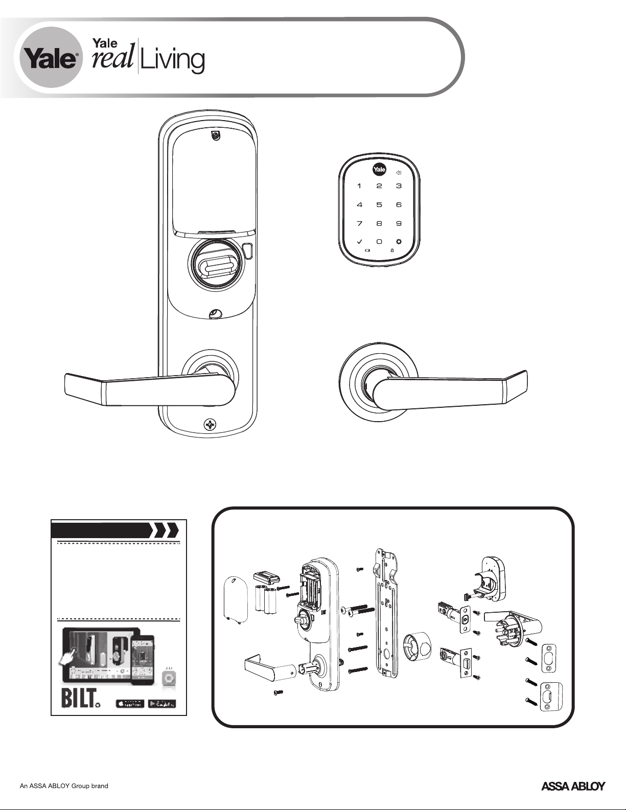
® ®
Yale Assure Lock
®
Interconnected Key Free Touchscreen
Installation and Programming Instructions
(YRC256)
Inside
of Door
4" Shown - 5.5" Available
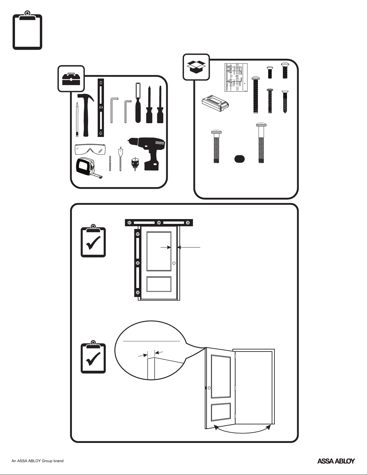
Before you begin
DOWNLOAD
THE BILT APP
for step-by-step installation
instructions & to register
your product
Outside
of Door
Smart Module
(Optional)
Retrofitting or modifying this product may impact fire rating, safety features and warranty.
Consult with code specifications to ensure compliance with all codes and ratings.
P/N YRL-EMICL-256-KFTSINSTL-FUL Rev A
1
Page 2
Before You Begin
Interconnected
Lockset
1" (25mm)1" (25mm)
2-1/8" (54mm)
2-1/8" (54mm)
2-3/4" (70mm)
Backset
2-3/8" (60mm)
"Backset" is the distance
4" (101mm)
from the door edge to the
center of the mounting
5-1/2" (139.7mm)
hole for the lever.
5/32"
(3.96mm)
1" (25mm)
1-3/8"
(35mm)
2-1/8" (54mm)
1-3/4"
(45mm)
Yale® is a registered trademark of Yale
2-3/8" (60mm)
Security Inc., an ASSA ABLOY Group
company. Copyright © 2016, Yale
Door Thickness
Security Inc., an ASSA ABLOY Group
Recommended Centerline
company.
All rights reserved. Reproduction in
36" (91 cm) From Floor.
whole or in part without the express
written permission of Yale Security Inc.
Caution: Although a door
is prohibited.
can be prepared by an
Caution: Copy machines
untrained person, Yale
may change the size of the
recommends that
template and make it
measurements and drilling
inaccurate.
be done by a skilled
carpenter or locksmith.
FOLD HERE
Door Edge
An ASSA ABLOY Group brand
Template
1-800-438-1951
www.yalelocks.com
263006837 (01-16)
x2
x1
3/32"
1/8"
1
1/8" 2-1/8"
1"
#2
Smart Module
M6x36mm
4-1/2"
Min
(114)
(Optional)
x2 Gold
PPHMS
(1-3/8")
x8
x2
x2
OR
x2 Black
M6x44mm
PPHMS
(Standard 1-3/4" - 2")
1-3/8" (35mm) Min to
1-3/4" (44.5mm) Max
2
P/N YRL-EMICL-256-KFTSINSTL-FUL Rev A
Page 3
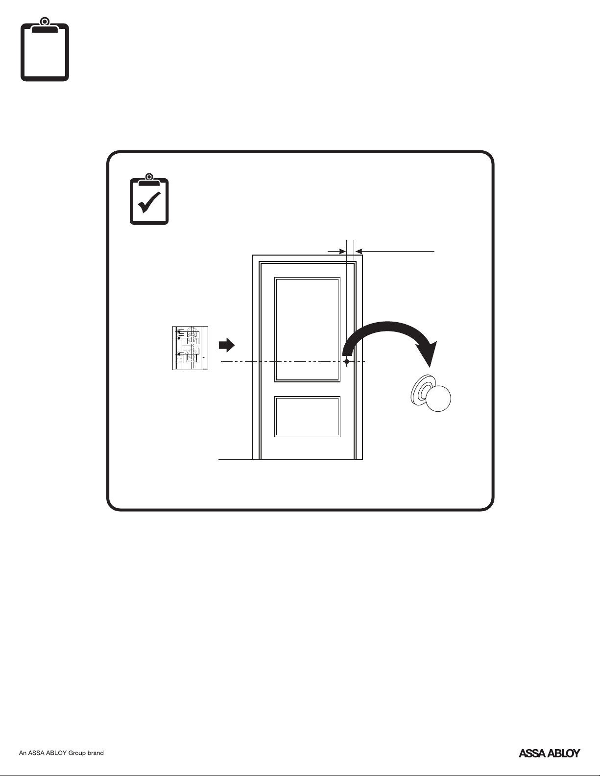
Mark Door Reference Lines
EXISTING
Interconnected
Lockset
1" (25mm)1" (25mm)
2-1/8" (54mm)
2-1/8" (54mm)
2-3/4" (70mm)
Backset
2-3/8" (60mm)
"Backset" is the distance
4" (101mm)
from the door edge to the
center of the mounting
5-1/2" (139.7mm)
hole for the lever.
5/32"
(3.96mm)
1" (25mm)
1-3/8"
(35mm)
1-800-438-1951
2-1/8" (54mm)
www.yalelocks.com
1-3/4"
(45mm)
Yale® is a registered trademark of Yale
2-3/8" (60mm)
Security Inc., an ASSA ABLOY Group
company. Copyright © 2016, Yale
Door Thickness
Security Inc., an ASSA ABLOY Group
Recommended Centerline
company.
All rights reserved. Reproduction in
36" (91 cm) From Floor.
whole or in part without the express
written permission of Yale Security Inc.
Caution: Although a door
is prohibited.
can be prepared by an
Caution: Copy machines
untrained person, Yale
may change the size of the
recommends that
template and make it
measurements and drilling
inaccurate.
be done by a skilled
carpenter or locksmith.
FOLD HERE
Door Edge
263006837 (01-16)
An ASSA ABLOY Group brand
Template
2-3/8" or 2-3/4"
Backset
O
M
V
E
R
C
L
E
3
P/N YRL-EMICL-256-KFTSINSTL-FUL Rev A
Page 4
1
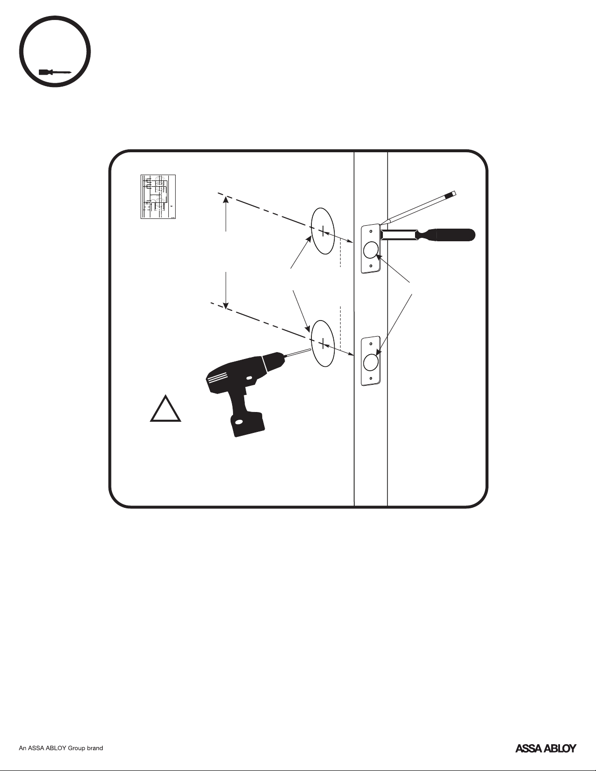
Preparing Door (if necessary)
Interconnected
Lockset
1" (25mm)1" (25mm)
2-1/8" (54mm)
2-1/8" (54mm)
2-3/4" (70mm)
Backset
2-3/8" (60mm)
"Backset" is the distance
4" (101mm)
from the door edge to the
center of the mounting
5-1/2" (139.7mm)
hole for the lever.
5/32"
(3.96mm)
1" (25mm)
1-3/8"
(35mm)
1-800-438-1951
2-1/8" (54mm)
www.yalelocks.com
1-3/4"
(45mm)
Yale® is a registered trademark of Yale
2-3/8" (60mm)
Security Inc., an ASSA ABLOY Group
company. Copyright © 2016, Yale
Door Thickness
Security Inc., an ASSA ABLOY Group
Recommended Centerline
company.
All rights reserved. Reproduction in
36" (91 cm) From Floor.
whole or in part without the express
written permission of Yale Security Inc.
Caution: Although a door
is prohibited.
can be prepared by an
Caution: Copy machines
untrained person, Yale
may change the size of the
recommends that
template and make it
measurements and drilling
inaccurate.
be done by a skilled
carpenter or locksmith.
FOLD HERE
Door Edge
263006837 (01-16)
An ASSA ABLOY Group brand
Template
4"
or
5.5"
Ø2-1/8"
2-3/8"
or
2-3/4"
Ø1"
!
Drill holes 1/2 way thru
door then complete
from other side to
prevent splitting.
4
P/N YRL-EMICL-256-KFTSINSTL-FUL Rev A
Page 5
2
x4
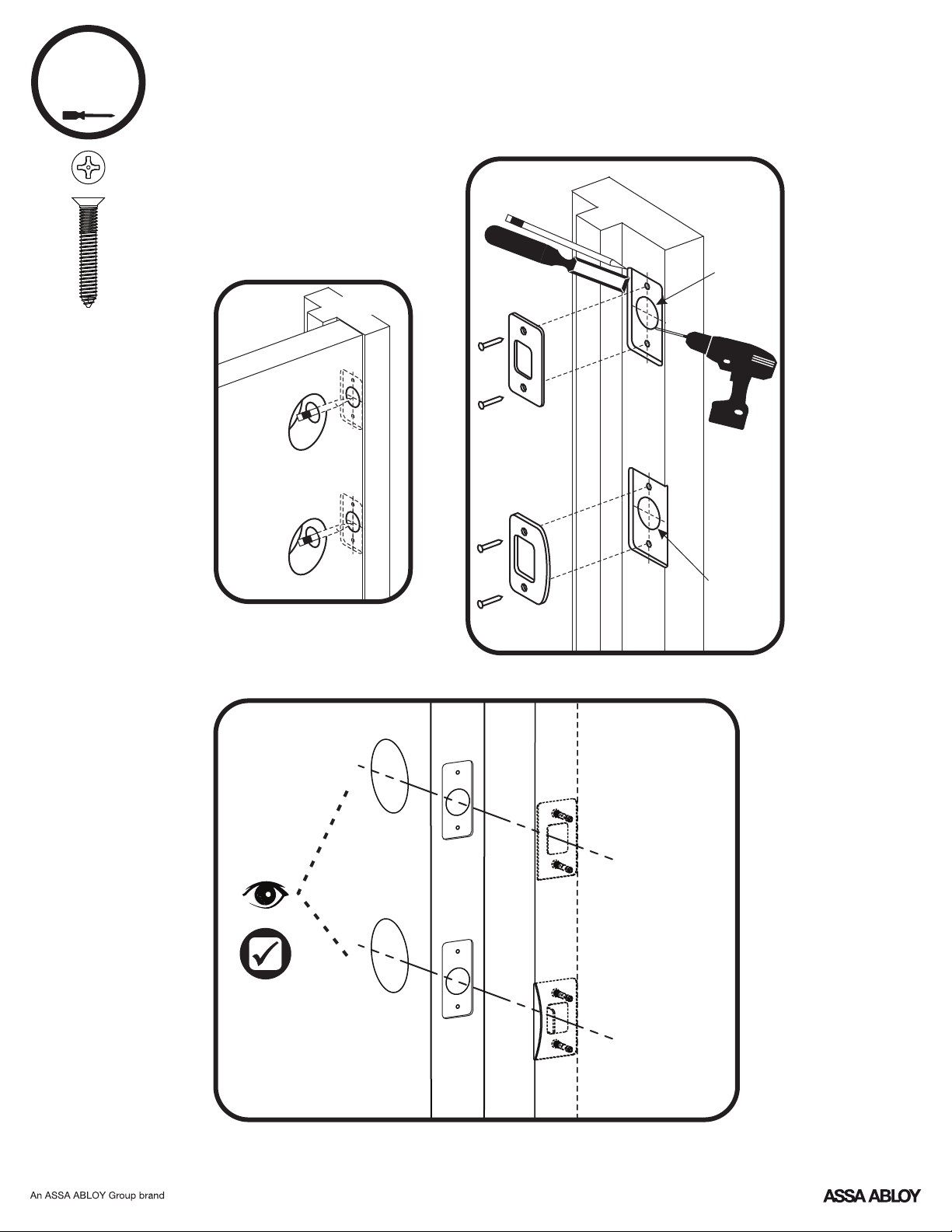
Installing Strike Plates
7-16 / 8-32 x 1" UNCWS
Frame
1" Dia. x
1"Deep
Frame
Inside
of Door
Door Frame
1" Dia. x
1/2"Deep
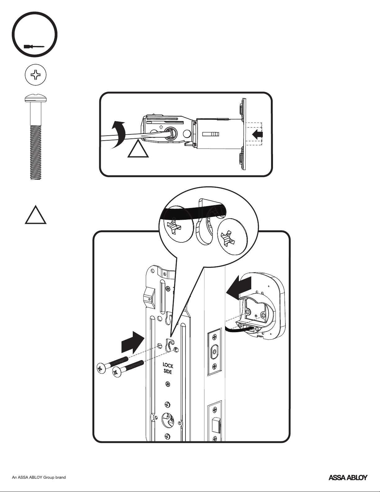
5
P/N YRL-EMICL-256-KFTSINSTL-FUL Rev A
Page 6
Determining Handing
The hand of a door is determined from the secure side of the
door. The term "secure" means the side from which you initially
unlock and enter.
Left Hand “LH”, Hinges Left.
Open Inward.
Left Hand Reverse "LHR", Hinges Left.
Open Outward.
Right Hand "RH", Hinges Right.
Open Inward.
P/N YRL-EMICL-256-KFTSINSTL-FUL Rev A
Right Hand Reverse "RHR", Hinges Right.
Open Outward.
6
Page 7
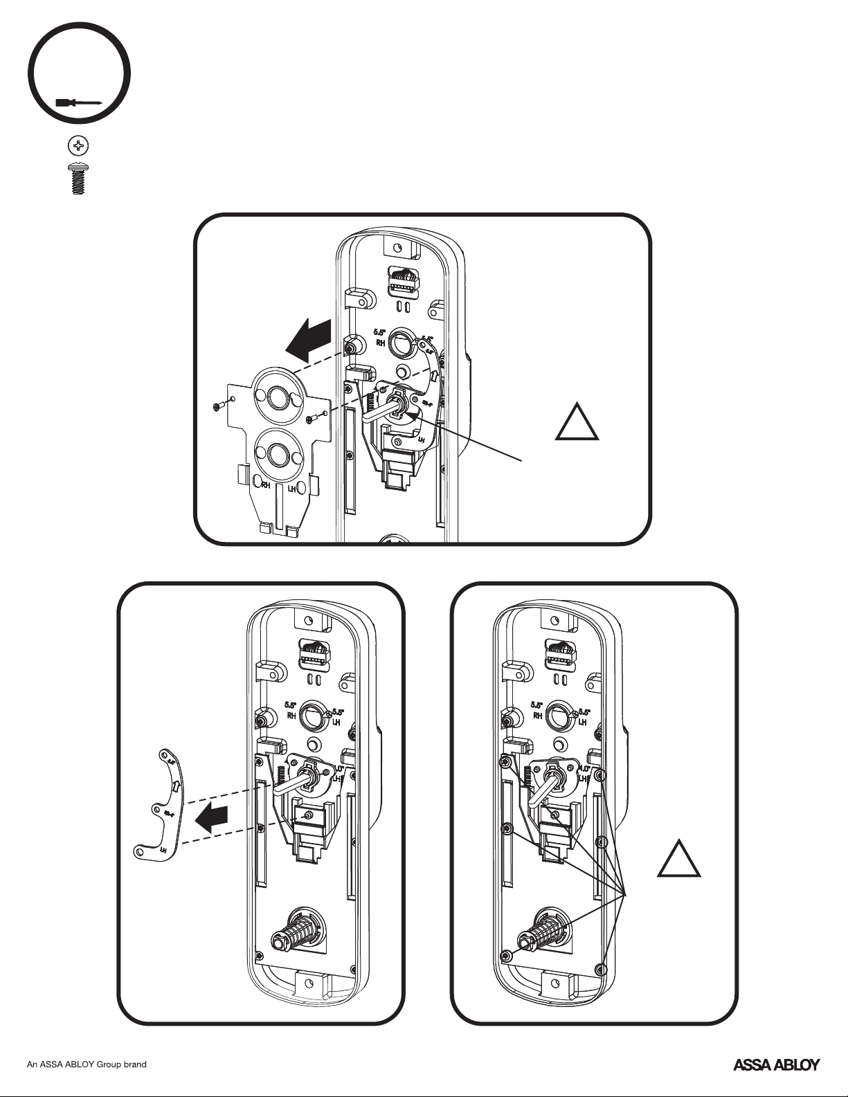
3
3
4-24 x 1/4" PPHMS
x2
Changing Handing (if necessary)
4" Left Hand to 4" Right Hand Shown
!
DO NOT TAMPER
WITH OR LOOSEN
E-CLIP AND ITS
ASSEMBLY
7
P/N YRL-EMICL-256-KFTSINSTL-FUL Rev A
!
DO NOT LOOSEN
THESE 6 SCREWS
OR REMOVE
COVER
Page 8
Changing Handing (if necessary)
3
continued
8
P/N YRL-EMICL-256-KFTSINSTL-FUL Rev A
Page 9
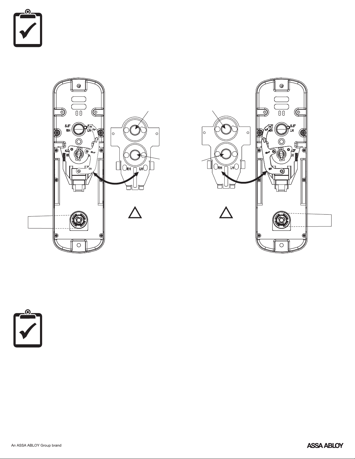
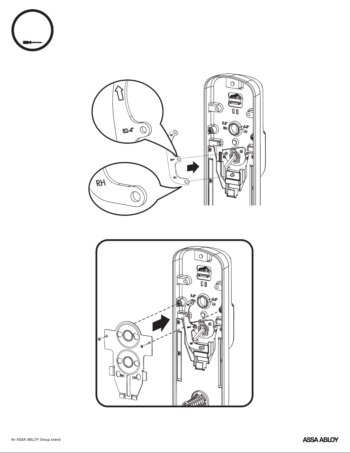
Lockset Handing Configurations
For 5.5"
4" Left Hand
!
Confirm LH is
visible thru LH hole
as shown for
left hand installation.
For 4"
For 5.5"
For 4"
4" Right Hand
!
Confirm RH is
visible thru RH hole
as shown for
right hand installation.
Test Lever and Thumbturn
After handing is changed, check that lever and thumbturn rotate freely.
9
P/N YRL-EMICL-256-KFTSINSTL-FUL Rev A
Page 10
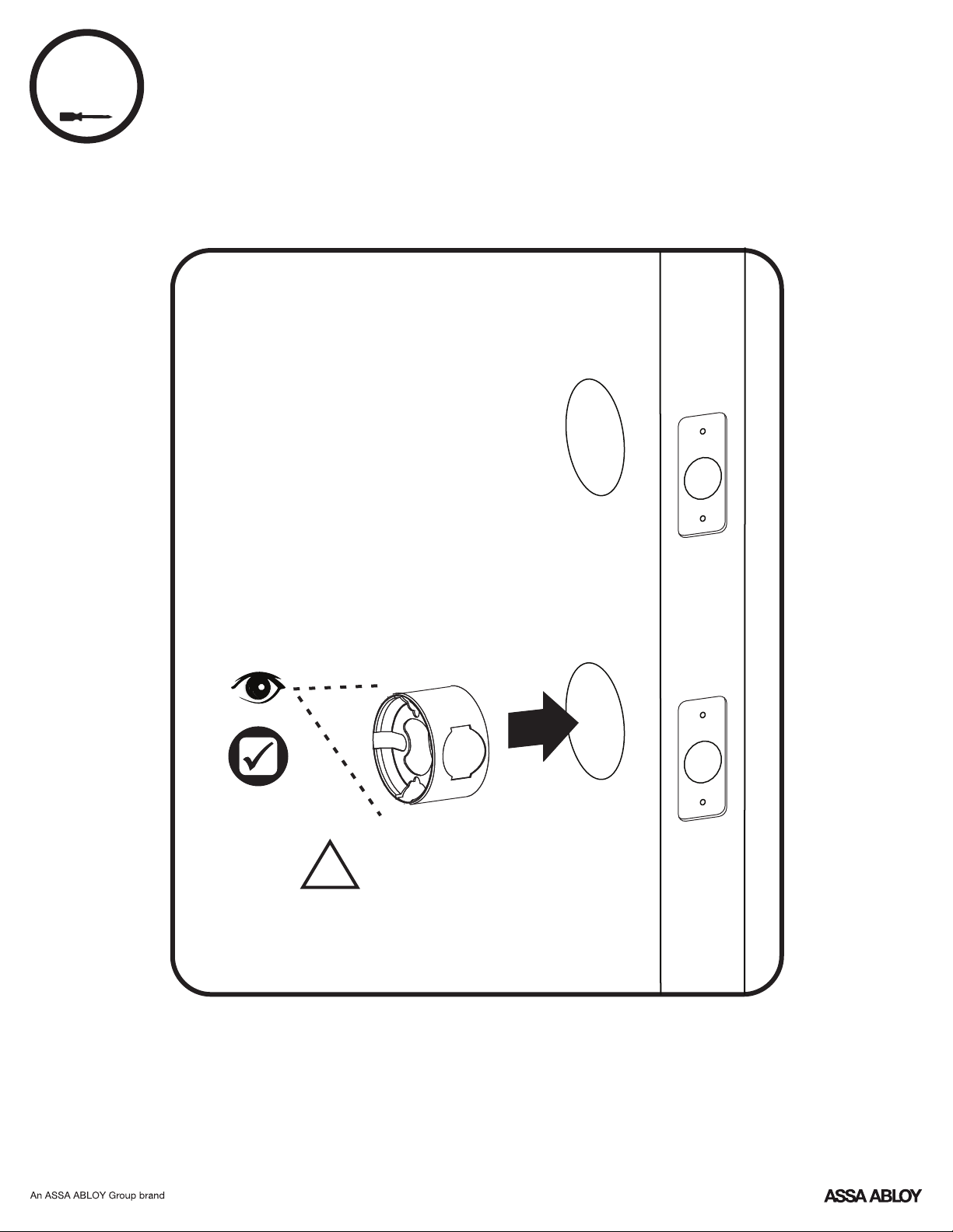
4
Installing Fire Cup
Inside of Door
!
Fire Cup and a UL marked
Latchbolt must be used to
qualify for UL listing.
P/N YRL-EMICL-256-KFTSINSTL-FUL Rev A
10
Page 11
5
Adjusting Deadbolt Latch
default
2-3/8" position
UP
O
optional
2-3/4" position
UP
Pull
Press
11
P/N YRL-EMICL-256-KFTSINSTL-FUL Rev A
Page 12
6
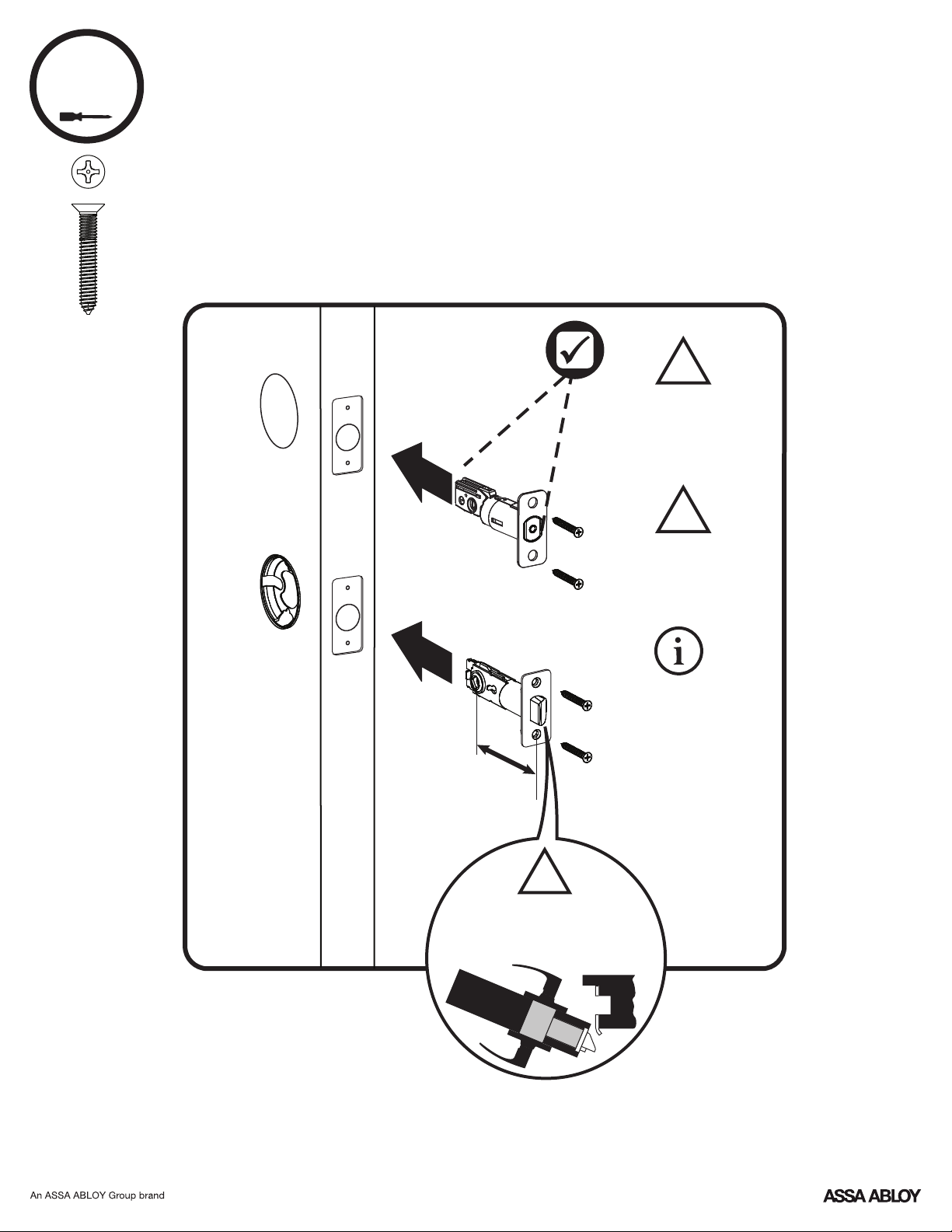
Installing Deadbolt Latch & Latchbolt
7-16 / 8-32 x 1" UNCWS
x4
Inside of Door
U
P
Choose latchbolt
based on backset.
(2-3/8" or 2-3/4")
!
Bolt must be in
retracted (unlocked)
position before
installing.
!
Ensure arrow
stamped on deadbolt
is UP.
Spacer collar
must be used for
1" edge bore.
Collar can be
removed for
3/4" edge bore.
Edge bore can be
3/4" or 1" only.
!
Curved edge
of latchbolt faces
direction door closes.
12
P/N YRL-EMICL-256-KFTSINSTL-FUL Rev A
Page 13
7
x2
Installing Exterior Deadbolt
M6x44 PPHMS for standard door thickness shown
UP
!
Confirm bolt is
retracted (unlocked).
!
Choose
through bolt
appropriate
for your door
thickness.
Inside of Door
13
P/N YRL-EMICL-256-KFTSINSTL-FUL Rev A
Page 14

8
Installing Lock Chassis
10-32 x 1-1/2" PPHMS
Inside of Door
x2
U
P
14
P/N YRL-EMICL-256-KFTSINSTL-FUL Rev A
Page 15

9
x2
Securing Back Plate to Door
#6-32 x 1/2" POHMS
Inside of Door
U
P
!
Drill two
pilot holes
Ø1/8"
x 1/2" deep
!
Two #6-32 x 1/2"
POHMS screws must
be used to qualify for
UL listing.
P/N YRL-EMICL-256-KFTSINSTL-FUL Rev A
15
Page 16

Testing Latchbolt Operation
Outside of Door
16
P/N YRL-EMICL-256-KFTSINSTL-FUL Rev A
Page 17

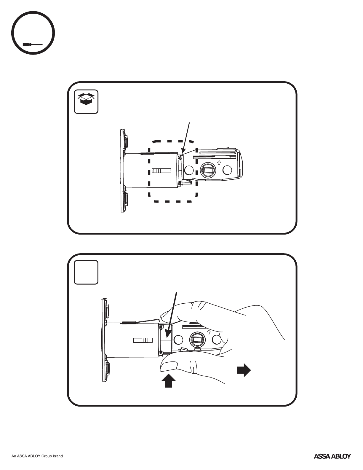
10
Attaching the Cable Assembly
!
Test that cables
are securely
connected.
Inside of Door
!
Avoid interference
with movement of lock
when routing cable.
U
P
17
P/N YRL-EMICL-256-KFTSINSTL-FUL Rev A
Page 18

11
Installing Interior Lock
!
Inside of Door
!
Turn
thumbturn
to adjust tailpiece
orientation.
U
P
18
P/N YRL-EMICL-256-KFTSINSTL-FUL Rev A
Page 19

11
Installing Interior Lock continued
10-32 x 5/8" POHMS
x1
6-32 x 1" PPHMS
x2
Inside of Door
!
DO NOT
LOOSEN
THIS SCREW
19
P/N YRL-EMICL-256-KFTSINSTL-FUL Rev A
Page 20

12
Installing Interior Lever
Inside of Door
"SNAP"
Inside of Door
Pull lever
to ensure
it is secure.
20
P/N YRL-EMICL-256-KFTSINSTL-FUL Rev A
Page 21

Testing Final Latchbolt Operation
Inside of Door
Outside of Door
21
P/N YRL-EMICL-256-KFTSINSTL-FUL Rev A
Page 22

Testing Final Deadbolt Operation
!
Confirm deadbolt
operates smoothly
with no resistance.
If resistance, re-
check installation
and confirm
mounting screws
have not been
over-tightened.
22
P/N YRL-EMICL-256-KFTSINSTL-FUL Rev A
Page 23

13
Installing Optional Smart Module
!
DO NOT install
Smart Module
with batteries in
unit. Damage
may occur.
23
P/N YRL-EMICL-256-KFTSINSTL-FUL Rev A
Page 24

14
Installing Batteries & Cover
"Welcome to
Yale Real Living."
Tighten screw
to replace cover.
!
Bolt must be
in retracted
(unlocked)
position
before
installing
batteries.
24
P/N YRL-EMICL-256-KFTSINSTL-FUL Rev A
Page 25

Handing the Lock
AFTER installing batteries and
cover or AFTER a factory reset,
activate touchscreen and create
Master PIN code. Lock will then
automatically determine handing.
See 1 of Programming
Instructions for how to set master
code.
Congratulations, you've installed the
® ®
Yale Assure Lock Interconnected Key Free Touchscreen (YRC256)!
Continue with the Programming Instructions
to customize your product.
25
P/N YRL-EMICL-256-KFTSINSTL-FUL Rev A
Page 26

Hardware Troubleshooting
Cycle lock in both the locked and unlocked positions. If problems are found:
Bolt will not extend and lock jam alarm occurs
a. Confirm manual operation.
b. Enter your Master PIN code.
c. With the bolt retracted, press menu Option 3 for Advanced Lock Settings.
d. Press Option 5 to rehand the lock.
e. Test the operation; locking the door via the keypad.
Door is binding
a. Check that door and frame are properly aligned and door is free swinging.
b. Check hinges: They should not be loose or have excessive wear on knuckles.
Bolt will not deadlock
a. Check for sufficient clearance of the bolt within the strike-side jamb.
Correct this by increasing the depth of the pocket for the bolt.
b. Check for misalignment of bolt and/or strike which may be preventing bolt
from properly entering the strike. With the door open, extend and retract the
bolt; if it is smooth, check the strike alignment.
Bolt does not extend or retract smoothly
a. Bolt and strike are misaligned, see above.
b. Check the backset of door relative to adjustments already made to bolt.
c. Verify proper door preparation and re-bore holes that are too small or
misaligned.
d. Verify touchscreen wire harness is routed properly (see Step 10).
e. Verify bolt is installed with correct side up (see Step 6).
Keypad numerics are scrolling
Remove interior lock and check to ensure that the wire harness is routed
properly (see Step 10).
NOTE TO INSTALLER AND CONSUMER
While Yale has included several features to prevent lockout
®
(9-Volt battery jumper, low battery warnings), it is still possible
for a lockout situation to occur. Because this product does not
have a mechanical override (a key), Yale recommends to use
®
this product in an environment where there are additional
entry points into the dwelling.
26
P/N YRL-EMICL-256-KFTSINSTL-FUL Rev A
Page 27

Programming Instructions
Exterior Escutcheon
Low Battery
Indicator
"P" Key
(Return to Previous)
Speaker
Lockout
Mode
Failsafe 9 volt
Battery Connection
(Use Alkaline battery)
Interior Escutcheon
Privacy
Button
Lock Activation
Master PIN Code must be created before any further programming.
Max User Codes = 250 with Z-Wave Plus or Zigbee network module
Max User Codes = 25 without network module or with iM1 network module
Max User Codes = 12 with Bluetooth
OR
OR
27
P/N YRL-EMICL-256-KFTSINSTL-FUL Rev A
Page 28

1
Creating Master PIN Code
Creating a Master PIN Code must be performed upon installation or after
resetting the lock to factory default. Programming and use of lock is not
possible until this step has been successfully completed.
"Register Master
Code. Press the gear
key to continue."
Enter 4-8
digit Master
PIN Code.
Press
"Enter a 4 to 8 digit
PIN code followed by
the gear key."
"Registered."
Press
28
P/N YRL-EMICL-256-KFTSINSTL-FUL Rev A
Page 29

2
Creating User PIN Codes
Master PIN code must be created first.
*Max user codes = 250 with Z-Wave or Zigbee network module
Max user codes = 25 without network module or with iM1 network module
Max user codes = 12 with Bluetooth
Enter Master
PIN code
Press
"Menu Mode,
enter number,
press the gear key
to continue."
Press
Press
Press
Press
Adding more *User Codes:
Press
Enter 4-8 digit PIN code
Press
Enter 4-8 digit PIN code
Press
(code flashes)
To end programming:
Press
29
P/N YRL-EMICL-256-KFTSINSTL-FUL Rev A
Page 30

3
Unlocking Door with PIN Code
Enter PIN Code
Press
Code Chart
PIN Code Management (With Network Module - Up to 250 Users)
User Type
Master
User
User
User
User
User
User
User
User
User
User
User
Duplicate if necessary
User Name
PIN Code
User
User
User
User
30
P/N YRL-EMICL-256-KFTSINSTL-FUL Rev A
Page 31

Resetting Lock to Factory Default
When resetting the lock, all user codes,
including the Master PIN code*, are deleted. All
programming features are reset to original
default settings (see below).
1. Remove the battery cover and batteries.
2. Remove the interior lock to access the reset
button hole. (See image at right.)
3. Re-insert 3 batteries and insert a small
screwdriver into the hole; holding the reset
button for 3 seconds.
4. While still holding the reset button, insert the
4th battery and hold the reset button for an
additional 3 seconds.
5. Release the reset button.
6. Re-install the interior lock onto the door.
Upon reset, Master PIN Code creation is the
only option available and must be performed
prior to any other programming of the lock.
For best results, the lock should be installed on the
door when resetting the lock to factory default. If the
process was done and the lock was not installed on
the door, review the Re-Handing instructions listed in
Hardware Troubleshooting.
Interior Lock
(4" Shown)
Reset Button
Access
Factory Settings
Settings
Master PIN Code
Automatic Re-lock
Inside Indicator Light
One Touch Locking
Privacy Button Setting
Volume Setting
Language Setting
Wrong Code Entry Limit
Shutdown Time
*The Master PIN code must be registered prior to any other
programming of the lock.
Factory Setting
Registration required*
Disabled
Disabled (Off)
Enabled
Disabled
Enabled (Low)
English
DisabledLockout Mode
5 Times
60 Seconds
31
P/N YRL-EMICL-256-KFTSINSTL-FUL Rev A
Page 32

Definitions
All Code Lockout Mode: This feature is enabled by the Master code. When enabled, it restricts all user (except Master)
PIN code access. When attempting to enter a code while the unit is in Lockout, the RED locked padlock will appear on
the screen.
Automatic Re-lock Time: After a successful unlock, the unit will re-lock automatically after duration selected in the
Advanced Lock Settings (Main Menu selection #3).
Handing the Lock: Lock handing refers to which direction the bolt comes out of the door (right or left). If the lock was
programmed off the door, the lock may need adjusting. Review Handing the Lock instructions and/or Re-Handing
instructions listed in Hardware Troubleshooting.
Inside Indicator Light: Located on the interior escutcheon. Shows active status (Locked) of lock and can be enabled or
disabled in the Advanced Lock Settings (Main Menu selection #3).
Language Setting Mode: Choosing English (1), Spanish (2) or French (3) becomes the (default) setting for the lock's
voice prompts.
Low Battery: When battery power is low, the Low Battery Warning indicator flashes RED. If battery power is completely
lost, use the 9Volt battery override. To use the 9V battery override apply 9V battery, in either direction, to terminals
below the touchscreen for backup power option. Wake up the lock and enter your pin code to unlock the door.
Master PIN Code: The Master PIN code is used for programming and for feature settings. It must be created prior to
programming the lock. The Master code will also operate (unlock/lock) the lock.
Network Module Setting: With the optional Network Module installed, this setting becomes available thru the Main
Menu (7) and allows the lock to connect with a network controller.
One Touch Locking: When the latch is retracted, activating the keypad will extend the latch (during Automatic Re-lock
duration or when Automatic Re-lock is disabled). When One-Touch Re-lock is not in use (disabled), any valid PIN code
will re-lock the lock.
Previous: While in Menu Mode, pressing this icon cancels the current operation and returns the user to the previous
step.
Privacy Mode: Privacy mode is disabled by default. Enable Privacy mode by pressing the privacy button for 4 seconds
to put lock in do-not-disturb mode (all pin codes are disabled).
Shutdown Time: The unit will shutdown (flashing RED) for sixty (60) seconds and not allow operation after the wrong
code entry limit (5 attempts) has been met.
Tamper Alert: Audible alarm sounds if attempting to forcibly remove outside lock from door.
User PIN Code: The user code operates the lock. The maximum number of user codes with Z-Wave Plus or Zigbee
network module is 250; without network module or with iM1 network module, maximum is 25; with Bluetooth,
maximum is 12. Note: When deleting user pin code(s), screen will display user pin code being deleted.
Volume Setting Mode: The volume setting for PIN code verification is set to Low (2) by default; otherwise it can be set
to High (1) or Silent (3) for quiet areas.
Wrong Code Entry Limit: After five (5) unsuccessful attempts at entering a valid PIN code, the unit will shut down and
not allow operation for sixty (60) seconds.
32
P/N YRL-EMICL-256-KFTSINSTL-FUL Rev A
Page 33

Feature Programming Through Menu Mode
Using Master PIN code*
1. Touch screen with back of hand or palm to activate.
2. Enter 4-8 digit master PIN code* followed by key.
Lock Response: "Menu mode, enter number, press key to continue."
3. Enter digit corresponding to the function to be performed followed by the key. Follow the voice commands.
*The Master PIN code must be registered prior to any other programming of the lock.
Note: After Master PIN code is entered, lock will automatically hand itself. For best results, lock should be installed
on door during this process. If this process was done and lock was not installed on door, review the Re-Handing
instructions listed in Hardware Troubleshooting.
1
Master PIN Code Setting
User Codes
M
2
3
M
Enter
Delete
1~12: with Bluetooth
1~25: without network module or with iM1 network module
1~250: with Z-Wave Plus or Zigbee network module
U
U
Continue
Complete
Continue
Complete
Advanced Lock Settings
Volume Setting
Language Setting Mode
Lockout Mode
Automatic Re-lock
Inside Indicator Light
One Touch Locking
Privacy Button Setting
Handing the Lock
High
Low
Silent
English
Spanish
French
Enable
Disable
Disable
30 sec
60 sec
2 min
3 min
Continue
Enable
Disable
Enable
Disable
Enable
Disable
Preforms automatic
handing of the lock
Complete
Default settings
in bold.
**This function appears only with
network module installed.
***This function appears only with
P/N C620 installed.
**Network Module Setting
***Set-up Digital Keys
Join the Network
Exit the Network
33
P/N YRL-EMICL-256-KFTSINSTL-FUL Rev A
Page 34

Programming Troubleshooting
Symptom
Suggested Action
•
•
•
•
•
•
•
•
•
•
•
•
•
•
•
•
•
•
Check or gear
•
•
•
•
•
•
•
•
•
34
P/N YRL-EMICL-256-KFTSINSTL-FUL Rev A
Page 35

FCC:
Class B Equipment
This equipment has been tested and found to comply with the limits for a Class B digital
device, pursuant to Part 15 of the FCC Rules. These limits are designed to provide reasonable protection against
harmful interference in a residential installation. This equipment generates, uses, and can radiate radio frequency
energy and, if not installed and used in accordance with the instructions, may cause harmful interference to radio
communications. However, there is no guarantee that interference will not occur in a particular installation. If this
equipment does cause harmful Interference to radio or television reception, which can be determined by turning the
equipment off and on, the user is encouraged to try to correct the interference by one or more of the following
measures:
Ÿ Reorient or relocate the receiving antenna.
Ÿ Increase the separation between the equipment and receiver.
Ÿ Connect the equipment into an outlet on a circuit different from that to which the receiver is connected.
Ÿ Consult the dealer or an experienced radio/TV technician for help.
Warning: Changes or modifications to this device, not expressly approved by ASSA ABLOY Residential Group
could void the user's authority to operate the equipment.
Industry Canada:
This Class A digital apparatus meets all requirements of the Canadian Interference Causing
Equipment Regulations.
Cet appareillage numérique de la classe A répond à toutes les exigences de l'interférence canadienne causant des
règlements d'équipement.
Product Support Tel 1-855-213-5841 • www.yalehome.com
Yale® ,Yale Real Living® and Assure Lock® are registered trademarks of ASSA ABLOY Residential Group.
Other products' brand names may be trademarks or registered trademarks of their respective owners and are
mentioned for reference purposes only. © Copyright 2019. All rights reserved. Reproduction in whole or in part
without the express written permission of ASSA ABLOY Residential Group is prohibited.
35
P/N YRL-EMICL-256-KFTSINSTL-FUL Rev A
Page 36

® ®
®
Yale Z-Wave Plus Smart Module
Installation Guide
Please use this procedure only when network primary controller is missing
or otherwise inoperable.
Adding a Yale Z-Wave Plus Smart Module to your Assure Lock & Z-Wave System
®
1. Install the Yale Smart Module into the slot above the battery compartment
IMPORTANT: The batteries must be removed before removing the Yale Smart Module:
• Remove battery cover
• Remove batteries
• Insert or remove Yale Smart Module
• Reinstall batteries
• Reinstall battery cover
2. Open the Z-Wave system's smart home or alarm app on your smartphone or tablet
3. Follow the in-app instructions for adding a new device
4. On your lock keypad, enter your master entry code followed by the icon
5. Press the 7 key followed by the icon
6. Press the 1 key followed by the icon
Removing a Yale Z-Wave Plus Smart Module from your Assure Lock & Z-Wave System
®
1. On your lock keypad, enter your master entry code followed by the icon
2. Press the 7 key followed by the icon
3. Press the 3 key followed by the icon
4. Open the Z-Wave system's smart home or alarm app and follow the instructions for
removing a device
5. Remove the Yale Smart Module from the slot above the battery compartment
IMPORTANT: The batteries must be removed before removing the Yale Smart Module:
• Remove battery cover
• Remove batteries
• Insert or remove Yale Smart Module
• Reinstall batteries
• Reinstall battery cover
6. If you're adding a new Yale Smart Module, follow the instructions included with it
P/N AYR202-ZW-INSTAL-FUL Rev E
Page 37

Warning: Changes or modifications to this device, not expressly approved by ASSA ABLOY
Residential Group could void the user's authority to operate the equipment.
!
This device is a security enabled Z-Wave Plus product that is able to use encrypted Z-Wave Plus messages to
communicate to other security enabled Z-Wave Plus products. This device must be used in conjunction with a Security
Enabled Z-Wave Controller in order to fully utilize all implemented functions. This product can be operated in any ZWave network with other Z-Wave certified devices from other manufacturers. All non-battery operated nodes within the
network will act as repeaters regardless of vendor to increase reliability of the network.
FCC:
Contain FCC ID: U4A-YRHCPZW0FM
Model: YRMZW2-US
This equipment has been tested and found to comply with
the limits for a Class B digital device, pursuant to Part 15 of
the FCC Rules. These limits are designed to provide
reasonable protection against harmful interference in a
residential installation. This equipment generates, uses, and
can radiate radio frequency energy and, if not installed and
used in accordance with the instructions, may cause harmful
interference to radio communications. However, there is no
guarantee that interference will not occur in a particular
installation. If this equipment does cause harmful
Interference to radio or television reception, which can be
determined by turning the equipment off and on, the user is
encouraged to try to correct the interference by one or more
of the following measures:
Ÿ Reorient or relocate the receiving antenna.
Ÿ Increase the separation between the equipment and
receiver.
Ÿ Connect the equipment into an outlet on a circuit
different from that to which the receiver is connected.
Ÿ Consult the dealer or an experienced radio/TV technician
for help.
THIS DEVICE COMPLIES WITH PART 15 OF THE FCC RULES.
OPERATION IS SUBJECT TO THE FOLLOWING TWO
CONDITIONS.
(1) THIS DEVICE MAY NOT CAUSE HARMFUL INTERFERENCE,
AND (2) THIS DEVICE MUST ACCEPT ANY INTERFERENCE
RECEIVED, INCLUDING INTERFERENCE THAT MAY CAUSE
UNDESIRED OPERATION.
Industry Canada:
Contain IC: 6982A-YRHCPZW0FM
Model: YRMZW2-US
Section 7.1.2 of RSS-GEN Under Industry Canada
regulations, this radio transmitter may only operate using an
antenna of a type and maximum (or lesser) gain approved for
the transmitter by Industry Canada. To reduce potential radio
interference to other users, the antenna type and its gain
should be so chosen that the equivalent isotropically radiated
power (e.i.r.p.) is not more than that necessary for
successful communication.
En vertu des règlements d'Industrie Canada, cet émetteur
radio ne peut fonctionner avec une antenne d'un type et un
maximum (ou moins) approuvés pour gagner de l'émetteur
par Industrie Canada. Pour réduire le risque d'interférence
aux autres utilisateurs, le type d'antenne et son gain doivent
être choisies de façon que la puissance isotrope rayonnée
équivalente (PIRE) ne dépasse pas ce qui est nécessaire pour
une communication réussie.
Section 7.1.3 of RSS-GEN This Device complies with
Industry Canada License-exempt RSS standard(s). Operation
is subject to the following two conditions: 1) this device may
not cause interference, and 2) this device must accept any
interference, including interference that may cause
undesired operation of the device.
Cet appareil est conforme avec Industrie Canada RSS
standard exemptes de licence(s). Son fonctionnement est
soumis aux deux conditions suivantes: 1) ce dispositif ne
peut causer des interférences, et 2) cet appareil doit
accepter toute interférence, y compris les interférences qui
peuvent causer un mauvais fonctionnement du dispositif.
This radio transmitter 6982A-YRHCPZW0FM has been
approved by Industry Canada to operate with the antenna
types listed below with the maximum permissible gain
indicated. Antenna types not included in this list, having a
gain greater than the maximum gain indicated for that type,
are strictly prohibited for use with this device.
Le présent émetteur radio 6982A-YRHCPZW0FM a été
approuvé par Industrie Canada pour fonctionner avec les
types d'antenne énumérés ci-dessous et ayant un gain
admissible maximal. Les types d'antenne non inclus dans
cette liste, et dont le gain est supérieur au gain maximal
indiqué, sont strictement interdits pour l'exploitation de
l'émetteur.
CAN ICES-3B/NMB-3B
24/7 Tech Support : 1-855-492-0505 • www.yalehome.com
Yale® is a registered trademark of ASSA ABLOY Residential Group. Other products' brand names may
be trademarks or registered trademarks of their respective owners and are mentioned for reference
purposes only. © Copyright 2019. All rights reserved. Reproduction in whole or in part without the
express written permission of ASSA ABLOY Residential Group is prohibited.
Page 38

®®
®
Yale ZigBee Module
Installation and Programming Instructions
Installing the ZigBee Module
®
IMPORTANT: the batteries be removed priormust
to removing and/or inserting the network module:
• Remove battery cover.
• Remove batteries.
• Remove and/or insert network module.
• Reinstall batteries.
• Replace cover.
Enrolling/Unenrolling the Network Module:
This device is a security enabled ZigBee product that is able to use encrypted ZigBee
messages to communicate to other security enabled ZigBee products. This device must be
used in conjunction with a Security Enabled ZigBee Controller in order to fully utilize all
implemented functions. This product can be operated in any ZigBee network with other
ZigBee certified devices from other manufacturers. All non-battery operated nodes within the
network will act as repeaters regardless of vendor to increase reliability of the network.
To Enroll the Module (Inclusion Mode):
• Enter the 4-8 digit Master code followed by the key.PIN
• Press the key followed by the key.
• Press the key followed by the key.
To Unenroll the Module (Exclusion Mode):
• Enter the 4-8 digit Master code followed by the key.PIN
• Press the key followed by the key.
• Press the key followed by the key.
P/N 202- - - Rev CAYR ZB INSTAL FUL
Page 39

FCC:
FCC ID YRHCPZB FM: U4A- 0
Model: 2YRMZB
This equipment has been tested and found to comply with
the limits for a Class B digital device, pursuant to Part 15 of
the Rules. These limits are designed to provideFCC
reasonable protection against harmful interference in a
residential installation. This equipment generates, uses,
and can radiate radio frequency energy and, if not installed
and used in accordance with the instructions, may cause
harmful interference to radio communications. However,
there is no guarantee that interference will not occur in a
particular installation. If this equipment does cause harmful
Interference to radio or television reception, which can be
determined by turning the equipment off and on, the user is
encouraged to try to correct the interference by one or
more of the following measures:
Reorient or relocate the receiving antenna.
Increase the separation between the equipment and
receiver.
Connect the equipment into an outlet on a circuit
different from that to which the receiver is connected.
CTVonsult the dealer or an experienced radio/
technician for help.
This equipment complies with radiation exposureFCC
limits set forth for an uncontrolled environment. This
equipment should be installed and operated with minimum
distance 20cm between the radiator and your body. This
transmitter must not be co-located or operating in
conjunction with any other antenna or transmitter.
Industry Canada:
IC YRHCPZB FM: 6982A- 0
Model: 2YRMZB
This Device complies with Industry Canada License-exempt
RSS standard(s). Operation is subject to the following two
conditions: 1) this device may not cause interference, and
2) this device must accept any interference, including
interference that may cause undesired operation of the
device.
Le présent appareil est conforme aux d'IndustrieCNR
Canada applicables aux appareils radio exempts de licence.
L'exploitation est autorisée aux deux conditions suivantes:
(1) l'appareil ne doit pas produire de brouillage, et (2)
l'utilisateur de l'appareil doit accepter tout brouillage
radioélectrique subi, meme si le brouillage est susceptible
d'en compromettre le fonctionnement.
Important Note:
Radiation Exposure Statement:
This equipment complies with radiation exposure limitsIC
set forth for an uncontrolled environment. This equipment
should be installed and operated with minimum distance
20cm between the radiator and your body.
Note Importante: (Pour l’utilisation de dispositifs
mobiles)
Declaration d’exposition aus radiations:
Cet équipement est conforme aux limites d´exposition aux
rayonnements établies pour un environnement nonIC
contrôlé. Cet équipment doit être installé et utilisé avec un
mimimum de 20 cm de distance entre la source de
rayonnement et votre corps.
This device complies with Part 15 of the rules.FCC
Operation is subject to the following two conditions: (1) This
device may not cause harmful interference, and (2) this
device must accept any interference received, including
interference that may cause undesired operation. Any
changes or modifications not expressly approved by
manufacturer could void the user’s authority to operate the
equipment.
IMPORTANT! Any changes or modifications not expressly
approved by the party responsible for compliance could
void the user’s authority to operate this equipment.
Product Support Tel 1-855-213-5841 • www.yalehome.com
Yale Locks & Hardware is a division of Yale Security Inc., an ASSA ABLOY Group company.
Yale® and Yale Real Living® are registered trademarks of Yale Security Inc., an ASSA ABLOY Group Company.
Other products’ brand names may be trademarks or registered trademarks of their respective owners and are mentioned for reference purposes only.
Copyright © 2017, Yale Security Inc., an ASSA ABLOY Group company.
All rights reserved. Reproduction in whole or in part without the express written permission of Yale Security Inc. is prohibited.
IMPORTANT! Any changes or modifications not expressly
approved by the party responsible for compliance could
void the user’s authority to operate this equipment.
IMPORTANT! Tous les changements ou modifications pas
expressément approuvés par la partie responsable de la
conformité ont pu vider l’autorité de l’utilisateur pour
actioner cet équipment.
CAN ICES NMB-3B/ -3B
YALE, with its unique global reach and range of products, is the world's favorite lock
– the preferred solution for securing your home, family and personal belongings.
ASSA ABLOY is the global leader in door opening solutions,
dedicated to satisfying end-user needs for security, safety and convenience.
Page 40

®
Yale iM1 Network Module
Installation and Programming Instructions
Installing the Yale iM1 Network Module
IMPORTANT: the batteries must be removed prior
to removing and/or inserting the network module:
• Remove battery cover and batteries.
• Remove and/or insert Network Module.
• Reinstall batteries and battery cover.
®
Enrolling the iM1 Network Module:
The Yale iM1 Network Module must be used with a Yale Assure Lock or Yale nexTouch
Lock and cannot be used in conjunction with any other Yale Network Module.
To Enroll the Module:
•Enter the 4-8 digit Master PIN code followed by the key.
•Press the key followed by the key.
•Press the key followed by the key.
P/N AYR202-iM1-INSTAL-FUL Rev D
Page 41

®
®
Yale Secure App Connection
with Yale iM1 Network Module
®
Connecting the Yale Secure App with the Yale iM1 Network Module
1. After following steps listed on other side of page for enrolling module, download the Yale
Secure app from App Store .
2. Ensure Bluetooth is enabled on your iPhone , iPad or iPod touch , and that you're within a
® ® ® ®
®
foot of your Yale lock.
3. Open the Yale Secure app and agree to allow app to access your Home Data.
4. If you do not have a home already created, create a new home when prompted. Tap + to add
a new Yale Lock.
5. The app will search for your Yale Lock. Be sure that you are within close proximity (less than
two feet or so). When "Yale Lock" appears, tap to add.
*If lock does not appear, enter your Master Pin Code on lock keypad, tap gear, tap 7, tap
gear, tap 1 and then tap gear.
6. Scan your Accessory Setup Code; shown below, or manually enter within the app.
Accessory Setup Code
FCC:
Class B Equipment
This equipment has been tested and found to comply with the limits for a Class B digital device, pursuant to
Part 15 of the FCC Rules. These limits are designed to provide reasonable protection against harmful
interference in a residential installation. This equipment generates, uses, and can radiate radio frequency
energy and, if not installed and used in accordance with the instructions, may cause harmful interference to
radio communications. However, there is no guarantee that interference will not occur in a particular
installation. If this equipment does cause harmful Interference to radio or television reception, which can be
determined by turning the equipment off and on, the user is encouraged to try to correct the interference by
one or more of the following measures:
Ÿ Reorient or relocate the receiving antenna.
Ÿ Increase the separation between the equipment and receiver.
Ÿ Connect the equipment into an outlet on a circuit different from that to which the receiver is connected.
Ÿ Consult the dealer or an experienced radio/TV technician for help.
Industry Canada:
This Class A digital apparatus meets all requirements of the Canadian Interference Causing Equipment
Regulations.
Cet appareillage numérique de la classe A répond à toutes les exigences de l'interférence canadienne causant
des règlements d'équipement.
Warning: Changes or modifications to this device, not expressly approved by ASSA ABLOY Residential
Group could void the user's authority to operate the equipment.
Product Support Tel 1-855-213-5841 • www.yalehome.com
Yale®, Yale Real Living® and Assure Lock® are registered trademarks of ASSA ABLOY Residential Group. nexTouch™ is a trademark of ASSA ABLOY Residential Group. Other products’ brand names may be trademarks or registered
Apple®, iPhone®, iPad®, iPod touch® and Siri® are trademarks of Apple Inc., registered in the U.S. and other countries. HomeKit is a trademark of Apple Inc. Use of the Works with Apple HomeKit logo means that an electronic accessory
has been designed to connect specifically to iPod touch, iPhone or iPad, respectively, and has been certified by the developer to meet Apple performance standards. Apple is not responsible for the operation of this device or its compliance
with safety and regulatory standards. Use of the HomeKit logo means that an electronic accessory has been designed to connect specifically to iPod, iPhone, or iPad, respectively, and has been certified by the developer to meet Apple
performance standards. Apple is not responsible for the operation of this device or its compliance with safety and regulatory standards. Please note that the use of this accessory with iPod, iPhone, or iPad may affect wireless performance.
trademarks of their respective owners and are mentioned for reference purposes only. Copyright © 2019, ASSA ABLOY Residential Group. All rights reserved.
Reproduction in whole or in part without the express written permission of ASSA ABLOY Residential Group is prohibited.
 Loading...