

Page 1

ba-o.4.1.3-en-2.2-y
Before installing hoist, fill in the information below.
Refer to the Hoist and Motor data plates.
Model No. _____________________________________
Serial No. _____________________________________
Purchase Date _____________________________________
Voltage _____________________________________
Rated Load _____________________________________
Follow all instructions and warnings for inspecting, maintaining and operating this product.
The use of any hoist presents some risk of personal injury or property damage. That risk is greatly increased if proper
instructions and warnings are not followed. Before using this hoist, each operator should become thoroughly familiar with all
warnings, instructions and recommendations in this manual. Retain this manual for future reference and use.
Forward this manual to operator. Failure to operate equipment as directed in manual may cause injury.
Electronic Control Unit SLE 3
Operation Manual
Page 2

ba-o.4.1.3-en-2.2-y
Page 3

09.2019 3
ba-o.4.1.3-en-2.2-y
Contents
1 General information .......................................................................................................................................................................................... 5
1.1 General information on these operating instructions .................................................................................................................................. 5
1.2 Contents of the operating instructions .......................................................................................................................................................... 5
1.3 Approvals / Test marks ..................................................................................................................................................................................... 5
1.4 Disclaimer / Loss of warranty .......................................................................................................................................................................... 5
1.5 Symbols .............................................................................................................................................................................................................. 6
1.6 Target group ....................................................................................................................................................................................................... 7
1.7 Warranty claims ................................................................................................................................................................................................. 7
1.8 Misuse ................................................................................................................................................................................................................. 7
1.9 Commissioning / Operation / Documentation ............................................................................................................................................... 7
1.10 Standards and directives .................................................................................................................................................................................. 8
1.11 Intended use ....................................................................................................................................................................................................... 8
2 General safety instructions .............................................................................................................................................................................. 9
2.1 Installation requirements .................................................................................................................................................................................. 9
2.1.1 Protective conductor .................................................................................................... 9
2.2 Residual risks ................................................................................................................................................................................................... 10
3 Product and functional description .............................................................................................................................................................. 11
3.1 Description ....................................................................................................................................................................................................... 11
3.2 Load sensor ...................................................................................................................................................................................................... 11
3.3 Front view ......................................................................................................................................................................................................... 12
3.4 Block diagram SLE 3 ....................................................................................................................................................................................... 13
3.5 Schematic circuit diagram ............................................................................................................................................................................. 14
3.6 Safety functions ............................................................................................................................................................................................... 14
3.6.1 Overload cut-off .......................................................................................................... 14
3.6.2 Sensor errors .............................................................................................................. 15
3.7 Control and monitoring functions ................................................................................................................................................................. 15
3.7.1 Actuation ..................................................................................................................... 15
3.7.2 Relay outputs ............................................................................................................. 16
3.7.3 Motor management .................................................................................................... 16
3.7.4 Operating time counter .............................................................................................. 18
3.7.5 Temperature monitoring for hoist and travel motors ................................................. 18
3.7.6 Signaling relays .......................................................................................................... 19
4 Installation ........................................................................................................................................................................................................ 20
4.1 Dimensions ....................................................................................................................................................................................................... 20
4.2 Attachment possibilities ................................................................................................................................................................................. 20
4.3 Cable connection ............................................................................................................................................................................................. 20
4.4 Cables ............................................................................................................................................................................................................... 20
4.5 Mounting ........................................................................................................................................................................................................... 20
5 Commissioning, tests, settings and maintenance ..................................................................................................................................... 21
5.1 Commissioning and regular tests ................................................................................................................................................................. 21
5.2 Change to the cut-off point ............................................................................................................................................................................ 22
5.3 Settings ............................................................................................................................................................................................................. 22
5.3.1 Testing bay function ................................................................................................... 22
5.3.2 Activating the testing bay function ............................................................................. 23
5.4 Crane test .......................................................................................................................................................................................................... 24
5.4.1 Activation of the function "Crane test": ...................................................................... 24
5.4.2 Deactivation of the crane test .................................................................................... 24
5.5 Documentation of changes to the cut-off point .......................................................................................................................................... 25
5.6 Device or sensor replacement ....................................................................................................................................................................... 26
5.7 Maintenance ..................................................................................................................................................................................................... 26
5.8 Wear parts ........................................................................................................................................................................................................ 26
6 Error and warning messages, faults ............................................................................................................................................................. 27
6.1 Operation .......................................................................................................................................................................................................... 27
6.2 Error state indicators ...................................................................................................................................................................................... 28
6.3 Warning messages .......................................................................................................................................................................................... 29
7 Decommissioning............................................................................................................................................................................................ 30
8 Technical data .................................................................................................................................................................................................. 31
8.1 Rating plates .................................................................................................................................................................................................... 33
Page 4

4 09.2019
ba-o.4.1.3-en-2.2-y
8.2 Type designation ............................................................................................................................................................................................. 33
Page 5

1 General information
09.2019 5
ba-o.4.1.3-en-2.2-y
1 General information
1.1 General information on these operating instructions
These operating instructions serve as safety manual in the sense of the safety standards for functional safety of the SLE 3 electronic control unit for the manufacturer's
hoists. They are aimed at the manufacturers, operators, commissioning engineers and
service personnel of hoists.
They contain requirements and information on intended use of the safety-based control
unit.
They must be available to the technical personnel of the machine manufacturer or
machine operator during the complete period of use and be followed at all times for
assembly, electrical installation, configuration, commissioning, maintenance and
diagnosis.
The safety instructions must be followed.
The chapter "Safety instructions" in the original operating instructions for the hoist
contains further requirements, and the chapter "Electrical installations" provides further
information and explanations, which must also be followed.
1.2 Contents of the operating instructions
These operating instructions contain information on the following subjects:
• Safety instructions
• Product and functional description
• Installation
• Commissioning and settings
• Testing
• Maintenance
• Error and warning messages, faults
• Decommissioning
• Technical data
• Approvals
The necessary expertise needed for planning and use of protective devices is not given
or imparted in the operating instructions.
1.3 Approvals / Test marks
See chapter - Technical data.
1.4 Disclaimer / Loss of warranty
The fundamental requirement for safe operation and achievement of the specified
product properties and performance features is:
• compliance with the operating instructions.
• Non-compliance will lead to a loss of liability and the warranty for the device and
hoist.
Page 6
1 General information
6 09.2019
ba-o.4.1.3-en-2.2-y
1.5 Symbols
The safety instructions in the manual are subdivided according to the severity of
the hazard and the likelihood of it occurring.
The measures described to avoid the hazards must be followed.
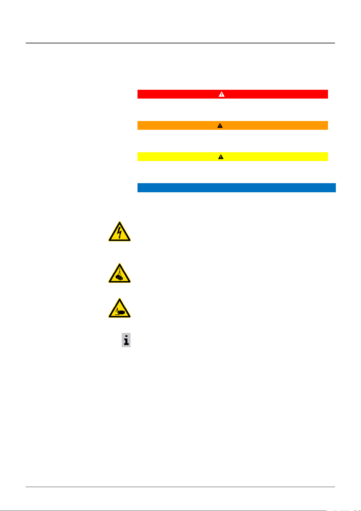
DANGER
This symbol warns of a direct danger to the health and life of people.
Disregarding these warnings will lead to severe injuries, possibly also death.
WARNING
This symbol warns of possibly dangerous situations for the health and life of people.
Disregarding these warnings can lead to severe injuries, possibly also death.
CAUTION
This symbol warns of possibly dangerous situations for the health of people.
Disregarding these warnings can lead to injuries.
ATTENTION
This symbol warns of property and environmental damage.
Specific symbols:
Warning of electrical voltage
Covers such as hoods and lids marked with this symbol may only be opened by "electrically skilled persons or competent persons".
Touching live parts can lead directly to death.
Warning of a suspended load
Any lingering of people under a suspended load is prohibited.
There is a danger of injury and death!
Warning of hand injuries
Danger of crush and cut injuries to the hands and fingers. The personal protective
equipment required for the specified activity should be worn to avoid injuries.
Requirements / Recommendation
Especially important information and tips for use of the product.
Page 7
1 General information
09.2019 7
ba-o.4.1.3-en-2.2-y
1.6 Target group
ATTENTION
All work for installation and troubleshooting must be carried out by an electrically
skilled person, commissioning and maintenance by a competent person.
Electrically skilled person
An electrically skilled person is a person who on account of his technical training has
knowledge of and experience with electrical systems and, knowing the applicable
standards and regulations, is able to assess the work assigned to him and identify and
avert possible dangers.
The electrically skilled person must be familiar with operation of the product and
trained in this.
Definition of a competent person
A competent person is a person who on account of his vocational training, vocational
experience and recent vocational activity has the necessary technical knowledge to
test the equipment.
This person must be able to assess the safety of the system in dependence on the
case of use. Competent persons authorised to carry out certain maintenance work on
our products are the manufacturer's service technicians and trained technicians with
certificate.
1.7 Warranty claims
WARNING
Prerequisite for trouble-free operation of the device and fulfilment of warranty claims is
compliance with the operating instructions.
• Read the operating instructions before you work with the device.
• Always only use the device for its intended purpose. Pay attention to the contents in
the sections "Technical data", "Intended use" and "Misuse", particularly to the conditions for transport, storage, installation, commissioning and operation.
• These operating instructions only describe the basic functions of the device.
• Do not open the enclosure to make unauthorised changes to the device.
• Always switch off the power supply when carrying out maintenance work (e.g.
replacement of the device).
1.8 Misuse
WARNING
They device may only be used according to the instructions and information in this
manual.
1.9 Commissioning / Operation / Documentation
WARNING
The SLE 3 only achieves its safety function when it has been programmed accordingly.
The commissioning of a hoist must be documented. This documentation must also
contain the overload cut-off point. The signature of the qualified person and the operator
is needed after commissioning (section “Commissioning and testing”).
Page 8

1 General information
8 09.2019
ba-o.4.1.3-en-2.2-y
1.10 Standards and directives
ATTENTION
Hoists in which SLE control equipment is installed are subject to the following directives
• Machinery Directive 2006/42/EC and
• EMC Directive 2014/30/EU
The SLE 3 was built in accordance with the following valid European standards and
regulations:
• IEC / EN 60204-32 – "Safety of machinery – Electrical equipment of machines – Part
32: Requirements for hoisting machines"
• EN 14492-2 – "Cranes – Power driven winches and hoists – Part 2: Power driven
hoists"
• ISO / EN 13849-1 – "Safety of machinery – Safety-related parts of control systems –
Part 1: General principles for design"
1.11 Intended use
ATTENTION
The SLE 3
• may only be used for control of a manually controlled single hoist from the manufac-
turer.
• is intended for industrial installations and may only be used in accordance with the
information in the technical documentation and the information on the rating plate.
• contains a safety-related overload cut-off that can, with due regard to the corre-
sponding standards specifically applicable to the machines / systems, be used for
the above-mentioned machines and systems in conjunction with a load sensor (see
chapter "Load sensor" for specification) up to category 2, PL d, according to
EN 13849-1.
• is a configurable device that only performs the safety functions after setting of the
safety-related parameter "Overload cut-off point"; this parameter may only be
changed by a competent person.
• is used in the control equipment as a central safety device for overload protection.
• is used in the hoist control equipment to actuate the motor.
• monitors the temperature of the motor by means of a thermistor (PTC).
ATTENTION
• The circuit diagrams and schematic circuit diagrams delivered with the hoist must be
observed and implemented in control equipment built by the customer.
• When integrating the control equipment delivered by the manufacturer in a general
control system or higher-level PLC, the product standards for hoists and the technical specifications regarding the functionality, signal sequence and timing of the device must be followed.
• The plant manufacturer is responsible for the overall system.
All faults and warnings that are indicated must be corrected immediately. If this is not
possible, the device, and therefore also the hoist it controls, must be taken out of service
until the fault has been corrected.
CAUTION
Any other use of the device or changes to the device itself, also during assembly
and installation, will lead to the loss of all warranty claims against the manufacturer.
Page 9
2 General safety instructions
09.2019 9
ba-o.4.1.3-en-2.2-y
2 General safety instructions
WARNING
You must follow the safety instructions:
• National and international directives and regulations must be followed for assembly,
commissioning, operation and period tests, in particular the Machinery Directive
2006/42/EC, safety rules and country-specific safety regulations.
• The manufacturer and operator of the machine / system must coordinate and observe
all applicable safety regulations with the responsible authorities on their own responsibility.
• Detailed instructions for commissioning and tests are described in chapter 5.
2.1 Installation requirements
WARNING
For applications with the device, observe the following guidelines on electrical installation.
• Switch cabinet assembly, protection at least IP54.
• Implement wiring according to EN 60204-32.
• The load sensor cable must be shielded. Connect the shield to earth potential.
Observe the information in the chapter "Installation".
• The fuse may not exceed the value in the table "Technical data".
NOTICE
Sensor cables must be installed separately of main power cables, e.g. in spatially separate ducts or bundles.
2.1.1 Protective conductor
WARNING
With a missing protective conductor, an electric shock hazard exists. Material damage,
severe injuries or death can result.
➢ Connect the external protective earth system (PE) close to the terminals of the
phase conductor using a protective conductor for each mains connection.
Without a protective earth connection, malfunctions can arise during operation. The
protective earth connection facilitates protective equipotential bonding for protection
against electric shocks, as well as functional equipotential bonding for the avoidance of
electrical interference effects on electronic systems.
Page 10
2 General safety instructions
10 09.2019
ba-o.4.1.3-en-2.2-y
2.2 Residual risks
WARNING
Unexpected start-up:
• Is prevented after the power supply is restored.
• The actuation control must also ensure this.
Physical injuries, e.g. crushing, severed limbs or even death.
The safety instructions are to be followed and applied!
WARNING
Direct contact with the power supply:
Deadly touch voltages can arise:
• from faulty wiring
• from not disconnecting the power supply when working on the control equipment
Physical injuries can remain, e.g. ventricular fibrillation, skin burns.
• The electrically skilled person must take this into consideration and take suitable
precautions.
WARNING
Failure of one of the downstream power elements
• Downstream power elements are not monitored by the SLE 3.
• Failure is to be prevented by the designer of the control equipment by suitable choice.
• In the event of failure the operator must have the power element replaced immediate-
ly by a competent person.
Page 11

3 Product and functional description
09.2019 11
ba-o.4.1.3-en-2.2-y
3 Product and functional description
3.1 Description
The SLE 3 is an electronic control unit for hoists. The device can be used to control polechanging or frequency-controlled drives. It contains a safety-related overload cut-off for
hoists in conjunction with a load sensor. It is a configurable system that only performs the
overload protection function after parameterisation and storage of the safety-relevant
parameter (overload cut-off point) in that the lifting movement is switched off safely.
The device also carries out other, non-safety related control and monitoring functions:
• Temperature monitoring for hoist and travel motors
• Display of system states via signalling relays
• Control of the lifting movements with motor management
• Counting of operating time
3.2 Load sensor
ATTENTION
The SLE 3 processes signals from passive DMS load sensors (see technical data).
The load sensor is a safety-relevant component. Due to this, only load sensors approved
by the manufacturer may be used. In the event of a defective load sensor, a sensor of
the same type must always be ordered and fitted. The load sensors are specified by the
manufacturer appropriately for the respective hoist and load and assigned internally.
Pay attention to the chapter "Device and sensor replacement" when replacing a load
sensor.
Fitting an unapproved load sensor will cancel the warranty and approval of the
device!
Page 12

3 Product and functional description
12 09.2019
ba-o.4.1.3-en-2.2-y
3.3 Front view
Display board
S1: Selector switch motor management
S4: Setting cut-off point, rough
S2: Setting cut-off point, fine
S3: DIP switch: to activate the testing bay
functions, relay operation and motor management
S5: Enter button: e.g. crane test
WARNING
The setting of the stored cut-off point may only be changed by a qualified person.
Unauthorized changes will void the warranty!
S1
S4
Signaling and
status LEDs
S5
S3
S2
Page 13

3 Product and functional description
09.2019 13
ba-o.4.1.3-en-2.2-y
3.4 Block diagram SLE 3
Legend
Supply
1: Power supply L
Analogue inputs load sensor
20: Ground DMS supply –S
21, 22: Load sensor input –IN / +IN
23: DMS power supply +S
2: Power supply reference point N
Actuation
3: Safety input lift S↑
4: Safety input lower S↓
5: Input fast S↕↕
Relay outputs hoist
6: Switching voltage of the relay L↑↓
7: Safety output lift slowly K↑
8: Safety output lift fast K↑↑
9: Safety output lower slowly K↓
10: Safety output lower fast K↓↓
Relay outputs cross travel
12...15 Relay outputs to
switch off the travel motors
if temperature too high left / right
1
16, 17: Thermistor input hoist motor 1
2
25, 26: Thermistor input travel motor 2
Signaling relay
27, 28: Signaling relay err
29, 30: Signaling relay option
ϑ1
ϑ2
Analogue inputs
load sensor
Signaling relay
Relay outputs
cross travel
Relay outputs
hoist
Control inputs
Power
supply
Connection terminals
Connection terminals
Page 14

3 Product and functional description
14 09.2019
ba-o.4.1.3-en-2.2-y
3.5 Schematic circuit diagram
3.6 Safety functions
3.6.1 Overload cut-off
The overload cut-off is designed according to Performance Level d, Category 2 in
accordance with ISO 13849-1.
As shown in the schematic circuit diagram, the DMS load sensor is supplied with power
(10 VDC) via the connections +S and -S. The load-proportional signal voltage ("load
signal") of the DMS sensor is connected at the connections +IN and -IN (mV).
The overload cut-off switches off in the following cases:
• If the signal voltage between the connections IN+ and IN- exceeds the cut-off thresh-
old setting while S↑ is active, the SLE 3 detects "overload" and switches the outputs
K↑ and K↑↑ off. The outputs are blocked until no overload is detected any more.
• If the signal voltage between the connections IN+ and IN- exceeds the cut-off thresh-
old setting while the outputs K↓ and K↓↓ are active or when stationary, the SLE 3
detects "overload" after a time of 800 ms and blocks the outputs K↑ and K↑↑ until
no overload is detected any more.
As a result of internal filter functions, the maximum response time of the cut-off when
lifting a load from the ground is 500 ms. For the total response time, the elasticity of the
crane system must also be taken into consideration.
"Overload" is acknowledged when the load on the hooks drops below 82.5 % of the
maximum lifting capacity and the safety input S↓ is active for a time of at least 2 seconds.
Switching of the outputs K↓ and K↓↓ is possible when an overload has been
detected!
Op. voltage
LIFT
Op. voltage
LOWER
Op. voltage
SIGNALS
Op. voltage
DRIVE
Load sensor
Page 15

3 Product and functional description
09.2019 15
ba-o.4.1.3-en-2.2-y
3.6.2 Sensor errors
The load signal (+IN/-IN) from the DMS sensor is processed internally in the SLE 3 on
two channels and monitored permanently.
The following three types of sensor errors are detected
• broken cable
• short circuit
• differential error between the internal measuring amplifiers in the device – internal
error.
NOTICE
See chapter "Error messages" on error diagnosis and correction.
In all three cases of sensor errors the output relays K↑ and K↑↑ are switched off in
dependence on the actuation of the safety inputs S↑ and S↕↕ and indicated as error
code by the device LEDs.
The maximum response time for cut-off of the outputs is:
▪ when input S↑ active = 850 ms
▪ when input S↑ not active = 1950 ms
A sensor error is acknowledged when:
• the cause of the error no longer exists
and
• the sensor signal is within the function limits and
• lift S↑ is not actuated.
WARNING
It remains possible to carry out the downwards movement (switching of the out-
puts K↓ and K↓↓) in the case of an overload or sensor error so that a suspended
load can be put down if necessary!
3.7 Control and monitoring functions
3.7.1 Actuation
The safety inputs S↑, S↓ and the input S↕↕ are read in in relation to N.
S↑ and S↓ are kept in the device on two channels in both controllers and evaluated
according to Category 2 Performance Level d.
Actuation of S↕↕ is only recognised if the corresponding direction S↑ or S↓ is active at
the same time.
If S↑ or S↓ is actuated from idle state, the SLE 3 switches the respective safety output
K↑ or K↓ after a maximum delay time of 300 ms.
Page 16

3 Product and functional description
16 09.2019
ba-o.4.1.3-en-2.2-y
3.7.2 Relay outputs
The relay outputs switch the voltage connected to L↑↓ through to the downstream
actuators (e.g. contactor). The control voltage at L↑↓ must correspond to the power
supply at L.
The safety outputs K↑ and K↑↑ are actuated by a safe internal circuit according to
Category 2 Performance Level d. This circuit switches the safety outputs K↑ and K↑↑ off
in the case of an error or overload.
The safety outputs K↓ and K↓↓ are also actuated by a safe internal circuit according to
Category 2 Performance Level d.
This circuit switches the safety outputs K↓ and K↓↓ off in the event of an error (e.g.
excessively high temperature at the hoist motor).
The safety output K↑↑ or K↓↓ is only active in conjunction with the safety output K↑ or
K↓ respectively.
3.7.3 Motor management
The term motor management relates to the off-times for the lifting and lowering movements.
The off-times for the example of lifting are explained below:
Starting at slow speed ta:
If S↑ and S↕↕ are actuated together, K↑ is switched on first. At the end of the off-time ta,
K↑↑ is switched on.
Stopping at slow speed tb:
If K↑ and K↑↑ are active, the output K↑↑ is switched off first at the end of actuation of S↑
and S↕↕. After the deceleration time tb has passed, K↑ is no longer actuated either.
Off-time for slow (ts) and fast (tf) speed:
If S↑ or S↕↕ becomes inactive, K↑ and K↑↑ are also no longer actuated. If S↑ or S↕↕ is
switched on again directly afterwards, K↑ or K↑ and K↑↑ is only actuated again at the
end of the off-time for the slow ts or fast tf speed.
Off-time for reversal of direction tr:
When the actuation reverses direction, the hoist is first stopped and the corresponding
safety output is actuated at the end of the off-time tr.
The length of the follow-up and off-times is set with the switch S1 and
the DIP switch S3_1.
WARNING
Changes to the settings of S1 and S3_1 may only be carried out by a qualified
person!
Page 17

3 Product and functional description
09.2019 17
ba-o.4.1.3-en-2.2-y
Motor management table
This table shows the relationship between the settings and times:
Motor type
S1
S3
ts
tf
tr
ta
tb
[ms]
[ms]
[ms]
[ms]
[ms]
Unknown
0
600
1250
1250
500
500
12/2H33
1
250
500
500 0 250
12/2H42
2
250
500
500 0 250
12/2H62
3
250
500
500 0 250
12/2H71
4
400
750
750
300
300
12/2H72
5
400
750
750
300
300
12/2H73
6
400
750
750
400
400
12/2H91
12/2H92
7
600
1250
1250
500
500
Ex-Motor
A-xxx
A
400
750
750 0 0
Frequency-
controlled
F
0 0 0 0 0
Motor management parameters for motors from Yale and third-party motors
– F = Setting for operation with a frequency inverter
– In setting 8 … E, the highest setting, as in item 7, is retained
Operation with frequency inverter
When working with a frequency inverter, the switch S1 is set to "F" and the switch S3_1
to "on".
1 2 3 4 5 6 7 8
ON
1 2 3 4 5 6 7 8
ON
1 2 3 4 5 6 7 8
ON
1 2 3 4 5 6 7 8
ON
1 2 3 4 5 6 7 8
ON
1 2 3 4 5 6 7 8
ON
1 2 3 4 5 6 7 8
ON
1 2 3 4 5 6 7 8
ON
1 2 3 4 5 6 7 8
ON
1 2 3 4 5 6 7 8
ON
Page 18

3 Product and functional description
18 09.2019
ba-o.4.1.3-en-2.2-y
3.7.4 Operating time counter
The operating time counter integrated in SLE counts the total number of hours of
operation in which the hoist motor is actuated.
3.7.5 Temperature monitoring for hoist and travel motors
Thermistor input 1
The temperature of the hoist motor is monitored by default. When the motor thermistor
(input 1) is actuated, an error is indicated by the device LEDs and all lifting movements
(outputs K↓, K↓↓ and K↑, K↑↑,) are blocked.
The load can only be moved again after cooling of the hoist motor.
Thermistor input 2
The travel motor thermistor (PTC) is connected to input 2 (if two or more travel motors,
for all). When a travel motor thermistor responds, the SLE 3 switches the relay outputs
left/right off and reports this via the device LED (as warning) that the travel motor(s) can
no longer be actuated.
When the motor has cooled down, the error is acknowledged automatically by the SLE 3
and left/right is switched on again.
• All thermistors must correspond to the specifications of DIN 44080.
• All thermistors can be replaced with resistors of ~300 Ω if the motors used do not
have thermistors.
ATTENTION: The hoist or cross travel motor is then no longer protected against
overheating.
Please observe the chapter "Technical data"!
If there is no thermistor connected to 2, the warning signal can be suppressed by
switching the slide switch S3_2 on.
The relay outputs left/right are switched irrespective of this.
Page 19

3 Product and functional description
09.2019 19
ba-o.4.1.3-en-2.2-y
3.7.6 Signaling relays
CAUTION
The signalling relays “err” and "option" are used to output error messages and may not
be used for safety-relevant functions.
The signalling relays may only be parameterised by an electrically skilled person.
Both relays can be parameterised as normally-closed or normally-open contacts:
Relay
Normally-open
Normally-closed
option
S3_7 off
S3_7 on
err
S3_6 off
S3_6 on
err is switched in every error state that stops a lifting movement.
option is freely parameterisable. Parameterisation is dependent on the switch position
S3:
DIP switch:
Switch
S3_3
Switch
S3_4
Switch
S3_5
The option relay
0 0 0
does not switch
1 0 0
switches on overload
0 1 0
switches on overheating
1 1 0
switches on sensor error
0 0 1
switches on all errors that prohibit lifting and lowering
1 0 1
Switch-off pulse on overload: option relay switches
off for 500 ms and then on again
0 1 1
switches at 95 % of nominal load
1 1 1
not used
The settings are made during initial commissioning in the factory.
Page 20

4 Installation
20 09.2019
ba-o.4.1.3-en-2.2-y
4 Installation
4.1 Dimensions
• 100 × 110 × 75 mm (W × H × D)
4.2 Attachment possibilities
• Snap-on attachment on 35 mm top hat rail (EN 50022-35)
• Screw attachment enclosure bottom (M4) using pull-out sliders
4.3 Cable connection
See section “Technical data”.
4.4 Cables
Install sensor cables (load sensor, temperature sensor) and power lines separately of
each other. (Example: Installation in different ducts or spatially separate bundles)
The lengths of the cables for sensors and digital control signals may not exceed the
maximum values specified in the chapter "Technical data".
4.5 Mounting
Mounting in a switch cabinet, at least IP 54.
Page 21

5 Commissioning, tests, settings and maintenance
09.2019 21
ba-o.4.1.3-en-2.2-y
5 Commissioning, tests, settings and maintenance
WARNING
Commissioning, testing, setting and maintenance work may only be carried out by a
qualified person in accordance with this manual.
The manual for the hoist contain further safety instructions and information on the
electrical equipment, which must also be observed.
5.1 Commissioning and regular tests
ATTENTION
The commissioning engineer must have all necessary information on the plant and the
device available to him.
The test must extend to perfect interaction of the device with the controls of the hoist, the
safe state and assembly according to state work regulations and equipment-specific
safety rules (directives, product standards, BG rules/information).
The test results are to be documented in writing in a report, which is to be signed by the
tester. The report is to be kept at the installation site of the machine/plant.
There are the following types of tests:
1. Tests before initial commissioning and after changes (acceptance tests)
A test must be carried out before initial commissioning of the SLE 3 and after changes to the SLE 3 or components or units involved in the safety function.
A change is considered as all changes to the circuit, the control system, the configuration and the parameters of the SLE 3 and components or units involved in the
safety function. The aim of the tests is to establish that the requirements regarding
the hoist are fulfilled when using the SLE 3 and that the components and units involved in the safety function work perfectly in interaction with the SLE 3. The type of
use / attachment of the SLE 3 and the follow-up of the plant must also be tested.
Acceptance test: overload cut-off:
Lifting of a test load of 110 % of the maximum lifting capacity. The device must detect the overload and switch off the lifting movement at the latest after the load has
been lifted completely from the floor. According to DIN EN 14492-2, an overload may
not be lifted further than a distance of the maximum nominal lifting speed multiplied
by 1 s.
2. Regular tests
The purpose of regular testing is to systematically uncover and correct safety shortcomings (e.g. in the case of changes or manipulations) in the protective devices of
the plant after commissioning. According to § 3, par. 3 of the Industrial Safety Regulation, the type, scope and times must be determined and stipulated by the user on
an equipment-specific basis. A test period of at least once a year has proven to be
appropriate. The test intervals can also be shorter in the case of multi-shift operation,
heavy duty or unfavourable environmental conditions or due to national regulations.
This test also includes testing of the overload cut-off point with a test load of 110 %
of the maximum lifting capacity, safety testing for perfect functioning of the SLE 3,
inspection of the components, correct and proper attachment of the SLE 3 and testing of the interaction of the SLE 3 with the components and units involved in the
safety function. The test also includes checking whether the specified limit value for
the follow-up is not exceeded.
Page 22

5 Commissioning, tests, settings and maintenance
22 09.2019
ba-o.4.1.3-en-2.2-y
5.2 Change to the cut-off point
ATTENTION
If, when lifting the test load during initial commissioning, an overload is not detected or
the maximum lifting capacity cannot be lifted, a new cut-off point must be saved in the
device.
This change may only be made by an electrically skilled person with the help of the
testing bay function. The permissible setting range must be observed here.
Permissible setting range of the overload cut-off point:
Overload cut-off points between 12 and 30 mV can be set with the SLE 3. This corresponds to a HEX switch setting from the minimum value: S4 = 4 and S2= B (minimum
value) to the maximum value: S4 = C and S2 = 2.
ATTENTION
If the sensor value at 110 % of the maximum lifting capacity is greater or smaller than the
permissible range and a load sensor fault can be ruled out, a larger or smaller load
sensor must be used.
5.3 Settings
5.3.1 Testing bay function
WARNING
The testing bay function involves the setting and saving of an overload cut-off point in the
SLE 3. Errors in the activation sequence or when saving a new overload cut-off point can
lead to dangerous situations up to falling of the load. The testing bay function may
therefore only be used by an electrical qualified person.
Label on the inside of the front panel
Changes to the cut-off point must be documented in this manual in the section
“Documentation of changes to the cut-off point” and in the crane logbook, stating
the reason, and signed by the setter and operator. The new cut-off point must also
be noted on the label in the cover (see figure).
Preparations for activation of the testing bay function:
The following preparations should be made or organized before activating the testing bay
function:
• Get a test load of 110 % of the maximum lifting capacity ready.
• Get a load weighing the maximum lifting capacity ready.
• Carefully take off the front panel (device cover) of the SLE 3 with the help of a
screwdriver and put in a safe place.
S1
S4
S2
S3
ON
Date _______________
Factory Setup
Device Rev._________
Page 23

5 Commissioning, tests, settings and maintenance
09.2019 23
ba-o.4.1.3-en-2.2-y
5.3.2 Activating the testing bay function
The testing bay function can only be activated in stationary state and with
no overload on the hook.
Note the position of the switch S1.
The first 3 steps must be carried out in the order described within a
maximum time of 16 seconds, otherwise the testing bay function
cannot be activated or not finished completely.
1. Set S3 DIP switch 8 to "On". Lifting / Lowering is blocked
2. Set S1 on D
III
II I err
pwr
3. Press S5 until all LEDs light up permanently
4. Set S3 DIP switch 8 to "OFF". The red and all yellow LEDs flash: The
testing bay function is now active for 30 minutes. Lifting / Lowering is
enabled
5. Correct the offset of the load sensor:
→ No load on the hook → Press the button S5 until the red LED
stops flashing
6. Set S4 = C, S2 = F
7. Lift 110 % overload at slow speed and simultaneously turn S4 to the
left until II and "err" light up
8. Turn S4 one switch position to the right and put down the overload
9. Lift 110 % overload at slow speed and simultaneously turn S2 to the
left until II and "err" light up
10. Put down the 110 % overload
11. Test the cut-off point found. Lift 110 % overload again. The load
may not be picked up from the floor completely. II and "err" light up
12. Put down the 110 % overload
13. Lift the maximum lifting capacity
14. Lower the maximum lifting capacity
15. Save the new overload cut-off point by pressing the button S5 until the 3 yellow LEDs stop flashing. Saving is indicated by fast flashing
16. Set S1 back to the previously noted switch position, note the changes and confirm the settings by signing on the enclosure cover.
17. Restart the device.
When the crane test is finished, put the front panel (device cover) back on to the
SLE 3 to protect the electronic components against dust and foreign bodies.
S1
S4
S3
S2
S5
Page 24

5 Commissioning, tests, settings and maintenance
24 09.2019
ba-o.4.1.3-en-2.2-y
5.4 Crane test
WARNING
When commissioning a hoist, a so-called crane test must be carried out according to
manual. To enable this test, the function "Crane test", which increases the overload cutoff point, can be activated.
The function "Crane test" may only be activated by a qualified person in the presence of a crane expert for the purposes of carrying out the test.
The crane runway and crane bridge are tested with a load of 125 %. To enable this test,
the function "Crane test" can be activated. After activation of the function, the cut-off point
is set on 137.5 % of the maximum lifting capacity for 30 minutes. (125 % + 10 %)
5.4.1 Activation of the function "Crane test":
The crane test can only be activated in stationary state and with no overload on the hook.
The DIP switches S3 must correspond to the setting shown in the enclosure cover.
Preparation:
Carefully take off the front panel of the SLE 3 (transparent enclosure cover) with the help
of a screwdriver.
Activation procedure:
The following steps must be carried out within a time of 12 seconds; the function "Crane
test" is then active:
1. Press the button S5 for longer than 3 seconds and then let it go again
2. After a pause of 1 second, press the button S5 again for longer than 3 seconds until
the red LED begins to flash.
If an error occurs during the activation procedure for the crane test, the red LED
flashes three times. After this error indication, the crane test can be activated
again.
5.4.2 Deactivation of the crane test
The function "Crane test" is deactivated by:
• restarting the device
• pressing the button S5 until the red LED goes out
As soon as the crane test is finished, put the front panel (device cover) back on to
the SLE 3 to protect the electronic components against dust and foreign bodies.
Page 25

5 Commissioning, tests, settings and maintenance
09.2019 25
ba-o.4.1.3-en-2.2-y
5.5 Documentation of changes to the cut-off point
WARNING
After testing of the new cut-off point, it must be documented in the cover of the device, in
the following table and in the crane logbook with signatures and confirmed.
Failure to document a change in the cut-off point will lead to immediate loss of the
warranty and is grossly negligent.
Setting
Reason for change
Operator's
signature
Service technician's signature
NOTICE
There is a page with a table as shown above at the end of these operating instructions.
This page can be taken out (or copied) and used to document changes to the settings of
the SLE 3 in the test book.
S1
S4
S2
S3
ON
Date _______________
Modified Setup
Device Rev._________
S1
S4
S2
S3
ON
Date _______________
Modified Setup
Device Rev._________
S1
S4
S2
S3
ON
Date _______________
Modified Setup
Device Rev._________
S1
S4
S2
S3
ON
Date _______________
Factory Setup
Device Rev._________
Page 26

5 Commissioning, tests, settings and maintenance
26 09.2019
ba-o.4.1.3-en-2.2-y
5.6 Device or sensor replacement
ATTENTION
When replacing a device and/or sensor, the original state of the installation as on
delivery of the hoist must be restored. This means in particular that all cables must be
installed exactly and reconnected and earthed exactly as specified ex works.
The sensor cable, delivered in a length of 5 m, must be shortened accordingly. Correct
earthing of the cable shield at the shield clamp is particularly important.
Earthing cable shield:
WARNING
After replacement of a device or load sensor by a competent person, the commissioning
procedure (see the chapter "Commissioning and testing") must be repeated completely
and the reading of the operating time counter of the replaced device must be recorded in
the crane logbook.
5.7 Maintenance
All screw terminals must be checked for tightness during every maintenance assignment,
at the latest annually, and tightened if necessary.
5.8 Wear parts
ATTENTION
The SLE 3 does not have any wear parts. If a device is defective, it must be replaced
with an equivalent one. Here it must be ensured that the device has the following
properties:
• equal or higher-order hardware version
• equal or higher-order software version
• equal or higher-order temperature range of application
These properties are to be found on the rating plate of the respective device.
(See chapter "Technical data")
The device can be procured directly from the manufacturer or one of his sales partners.
The chapter "Device and sensor replacement" must be followed for installation.
10 mm
Page 27

6 Error and warning messages, faults
09.2019 27
ba-o.4.1.3-en-2.2-y
6 Error and warning messages, faults
WARNING
Testing of the electrical installation may only be carried out by an electrical qualified
person.
Changes to the overload cut-off point or a device replacement may only be carried out by
a qualified person.
6.1 Operation
The detailed description of errors is to be found in the "Service instructions of the
manual".
Internal tests are carried out when the power supply is switched on. The LEDs "pwr",
"err", "I", "II", "III" light up during this test.
The SLE 3 is ready for operation when only the LED "pwr" is still on.
Symbols
LED is off LED flashes LED lights up
III
II I err
pwr
Cause
Consequence
Correction
Device is ready for operation
Page 28

6 Error and warning messages, faults
28 09.2019
ba-o.4.1.3-en-2.2-y
6.2 Error state indicators
The SLE 3 constantly carries out internal tests and tests on the connected sensors and
monitors the plausibility of external and internal switch states. If the SLE 3 detects a
problem, an error or error state is set and lifting or lifting and lowering is blocked.
The possible errors and their indication are described in the following table and must be
corrected before further operation is possible.
III
II I err
pwr
Cause
Consquence
Correction
Sensor error:
Broken cable, short
circuit
Lifting blocked
• Check load sensor connection: screw terminals for
tightness (-S, -IN, +IN, +S), correct wire assignment
per circuit diagram
• Measure sensor supply voltage (+S / -S): set point
value 9.5…10.5 V
• Measure the output voltage of the connected sensor
(-IN / -S, +IN / -S): value approx. 5 V
• Measure the sensor values at the disconnected
sensor: set point values:
between wires RED / BLACK: 350 … 400
between wires BROWN / ORANGE: 346 … 356
Overload
Lifting blocked
• Put down the overload and reduce the load
• Correct the cut-off threshold (during commissioning,
with test load)
Overheating 1 or
thermistor error
Lifting and
lowering
blocked
• Let the motor cool down →the error state is acknowl-
edged automatically
• Check the wiring of the thermistor
• Check the thermistor resistance with the motor cold:
– If the measured resistance is 150...750, the
thermistor input is defective and the device must
be replaced.
– If the resistance is greater or smaller, the thermis-
tor is defective and the motor must be replaced.
Offset correction error
Lifting blocked
• Existing device: check the load sensor → see above
• New device: carry out offset calibration
• If the error occurs in testing bay mode, then check the
load sensor wiring
Lifting and lowering
actuated at the same
time
Lifting and
lowering
blocked
• Error in the wiring.
• Check the control cables to the terminals 3, 4 and 5 at
the SLE
Internal error
Lifting and
lowering
blocked
• Check the voltage at terminal 6
• Restart the device
• If the error occurs again after a restart, the device
must be replaced
No power supply available, device fuse defective
Device does
not work
• Check the power supply of the device
Page 29

6 Error and warning messages, faults
09.2019 29
ba-o.4.1.3-en-2.2-y
6.3 Warning messages
A warning detected and indicated by the device does not lead to any restrictions in the
lifting movements. The warning is indicated by three LED indicators (flashing) on the front
side. A warning can lead to impairment of the travel motion.
III
II I err
pwr
Cause
Correction
Crane test mode is active.
Test load for the crane test can now be
lifted.
• The crane test mode can be deactivated by
restarting the device or pressing the button S5.
Error occurred while activating the testing
bay function or the crane test.
Revert the settings to the Hex and DIP switches and
start activation from the beginning again.
Overheating 2 or thermistor error
• Let the motor cool down →the error state is
acknowledged automatically
• Check the wiring of the thermistor
• Check the thermistor resistance with the motor
cold:
– If the measured resistance is 150...750, the
thermistor input is defective and the device
must be replaced.
– If the resistance is greater or smaller, the
thermistor is defective and the motor must be
replaced.
Overload cut-off point. Setting was manipulated.
• Set the overload cut-off point on the smallest-
possible value.
The set overload cut-off point is greater
than the greatest-possible cut-off point.
• Set the overload cut-off point on the smallest-
possible value.
The set overload cut-off point is smaller
than the smallest-possible cut-off point.
• Set the overload cut-off point on the smallest-
possible value.
Testing bay mode active: offset correction
not carried out
• Carry out sensor offset correction
Testing bay mode active: offset correction
carried out
ATTENTION
If an error cannot be corrected, the service department of the manufacturer or one
of his sales partners must be contacted.
Page 30

7 Decommissioning
30 09.2019
ba-o.4.1.3-en-2.2-y
7 Decommissioning
The operator is responsible for decommissioning of the plant and thus of the SLE 3.
Electronic components and electric and electronic scrap are special waste.
Country-specific environmental laws must be obeyed when disposing of the device.
The local authorities will provide relevant information.
The SLE 3 does not have any batteries or rechargeable batteries.
Page 31

8 Technical data
09.2019 31
ba-o.4.1.3-en-2.2-y
8 Technical data
Supply
Voltage variants
AC voltage:
24 V 50 / 60 Hz
42 V 50 / 60 Hz
48 V 50 / 60 Hz
110/120 V 50 / 60 Hz
230 V 50 / 60 Hz
DC voltage:
24 V DC
Residual ripple:
±5 %
Voltage tolerance
90 … 115 %
Power consumption at rated voltage
9 VA
Fuse protection control current circuit
6.3 A, slow blow
Actuation
Galvanic isolation
Yes
Signal level input inactive
< 40 %
of the supply
Signal level input active
> 70 %
Relay outputs
Control relays per EN 13849-1, Cat. 2
4
Utilization category
- EN 60947-5-1,
AC15: 250 V / 2 A (inductive load cos φ=0.7), 5 A (resistive load)
DC13: 30 V / 2 A
At +70 °C (optional)
AC15: 250 V / 1.5 A (inductive load cos φ=0.7), 3 A (resistive load)
Signaling relays / Temperature monitoring relay
4, volt-free
Utilization category
- EN 60947-5-1,
AC15: 250 V / 2 A (inductive load cos φ=0.7), 5 A (resistive load)
DC13: 30 V / 2 A
At +70 °C (optional)
AC15: 250 V / 1.5 A (inductive load cos φ=0.7), 3 A (resistive load)
Inputs load sensor
Load sensor type
Passive DMS sensor, full bridge
Supply DMS sensor +S
10 V DC ± 5 %
-S
0 V DC
Load signal input +IN
2 mV / V,
350
-IN
Measurement range
0...20 mV
Max. error of measurement at 25 °C referred to the
smallest-possible cut-off point
±3 %
Overload cut-off point
Parameterizable
PTC inputs
Maximum total initial resistance
Max. 1500 (IEC / EN 60947-8)
Pick-up resistance
2800 … 3500
Maximum release resistance:
1650
Environmental conditions
Insulation strength
Clearances and creepage distances per IEC / EN 60664
Rated insulation voltage 250 V AC
Pollution degree 2
Protection class II
Overvoltage categories III
Page 32

8 Technical data
32 09.2019
ba-o.4.1.3-en-2.2-y
Impact, vibrations
EN 60068-2-27 10 g – 11 ms
EN 60068-2-6 3 mm at 2...9 Hz; 0.5 g at 9...200 Hz
EMC
EN 61000-6-2-7 Immunity for devices intended to perform functions in safetyrelated systems (functional safety) at industrial sites
EN 61000-6-3 Emission standard for residential, commercial and light-industrial
environments
Temperature range operation
-20 °C ... +55 °C (standard)
-20 °C ... +70 °C (optional)
Storage
-40 °C ... +80 °C
Dimensions
100 × 110 × 75 mm (W × H × D)
Protection
IP20, EN 60529
Connection terminals
30 box terminals with captive plus-minus screws
Per box terminal: 1 × 4 mm2 solid or 1 × 2.5 mm2 stranded wire with wire ferrules
or 2 × 1.5 mm2 stranded wire, with wire ferrules
Tightening torque of the screw terminals 0.5 Nm
Attachment
Top hat rail EN 50022
Weight
0.5 kg
Mounting position
Horizontal, vertical
Maximum cable length
- Digital control signals
- Temperature inputs
- Sensor inputs (shielded)
100 m
50 m
5 m
Safety parameter values per ISO 13849-1
SLE 3
Performance level
d
PFH
5.28 E-07
MTTFd
100 years
DC
84 %
Category
2
Response time
850 ms
Requirements for sensors:
Performance level
c
PFH
< 1.08 E-06
MTTFd
>= 100 years
Category
1
Requirements for the contactor:
Performance level
c
PFH
< 1.32 E-06
B10d
> 1,300,000 (assumed cycles/year: 150,000)
Category
1
Page 33

8 Technical data
09.2019 33
ba-o.4.1.3-en-2.2-y
8.1 Rating plates
The type designation is to be found on the rating plate. The hardware and software
versions are also to be found on the rating plate.
Rating plate for countries without UL and CSA approval requirement:
Example:
Rating plate for countries with UL and CSA approval requirement:
There is currently not yet UL/CSA approval for the SLE 3.
8.2 Type designation
SLE
3 - (d2) - 1 1 0
Temperature range
Software version
Hardware version
Performance level and category per ISO
13849-1
Consecutive identification no.
Device name
Page 34

Annex
34 09.2019
ba-o.4.1.3-en-2.2-y
Changes to the SLE 3 device setting – Serial number: ....................................................
Setting
Reason for change
Operator's
signature
Service technician's
signature
S1
S4
S2
S3
ON
Date _______________
Modified Setup
Device Rev._________
S1
S4
S2
S3
ON
Date _______________
Modified Setup
Device Rev._________
S1
S4
S2
S3
ON
Date _______________
Modified Setup
Device Rev._________
S1
S4
S2
S3
ON
Date _______________
Modified Setup
Device Rev._________
S1
S4
S2
S3
ON
Date _______________
Modified Setup
Device Rev._________
S1
S4
S2
S3
ON
Date _______________
Modified Setup
Device Rev._________
S1
S4
S2
S3
ON
Date _______________
Factory Setup
Device Rev._________
Page 35

Annex
09.2019 35
ba-o.4.1.3-en-2.2-y
Notes
Page 36

Printed in Germany ba-o.4.1.3-en-2.2-y
USA: Ph: (800) 888.0985 • (716) 689.5400 • Fax: (716) 689.5644 • www.cmworks.com
SINGAPORE: Ph: +65 6268 9228-201 • Fax: +65 6268 9618 • www.cmworks.com
GERMANY: Ph: +49 7940 128-0 • Fax: +49 7940 55665 • www.stahlcranes.com
 Loading...