

Page 1
Pack contents
• 1 x HSA6020 PIR motion detector
• 2 x wall plugs
• 1 x 2.6 mm (diameter) x 10 mm cross
head fixing screws.
• 2 x 3.5 mm x 15 mm wall plugs
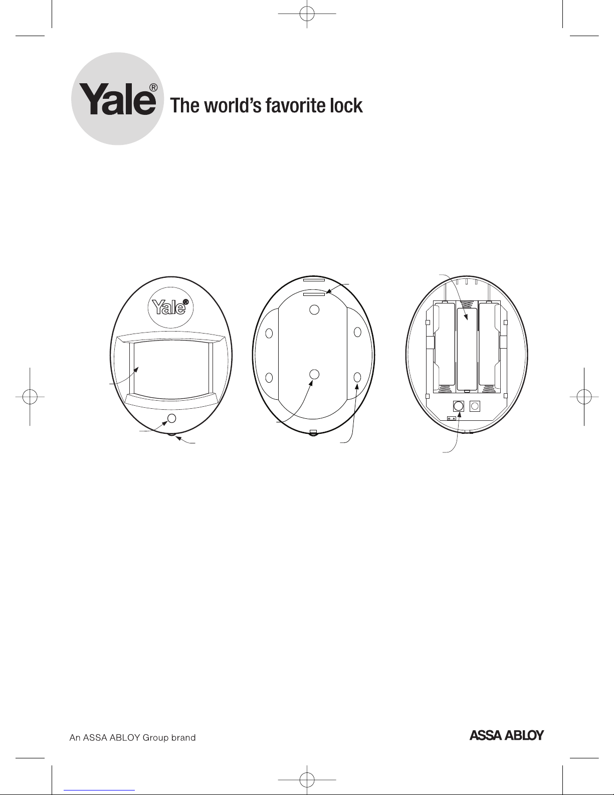
PIR detector description
Status LED: Hidden red LED shines
through lens to indicate door contact
state
Learn/Test button: Used for testing the
radio performance (No sleep time) and
for learning-in.
Cover screw: Provides access to inside
of PIR
Tamper Spring: Spring loaded switch to
protect the PIR from being opened.
Tab Slot: Pull out plastic tab to activate
battery.
Corner fixing knockouts: Punch
through to provide holes for corner
fixing.
Wall fixing knockouts: Punch through
to pr
ovide holes for flat mounting on
walls.
Batteries X 3: Battery compartment for
three AAA 1.5V alkaline cells.
Wirefree Yale HSA6020
PIR motion detector
(Yale part number: 666020001001)
Cover screw
Learn/Test
Button
Status
LED
Corner fixing
knockouts X 4
Wall fixing
knockouts X 2
T
ab slot
+
++
B
atteries X 3
Tamper spring
HSA6000 series
PIR Manual 8/12/06 11:53 am Page 1
Page 2
Specification
Conforms to:
EN 300 220-1 / V2.1.1 (2006-04)
EN 301 489 -1, / V1.6.1 (2004-12)
EN 301 489-3, / V 1.4.1 (2002-08)
Environmental conditions:
-10°C to 40°C, relative humidity
70% non-condensing
Radio: Microcontroller controlled
433.92MHz AM transmitter.
Battery: 4.5V 3 X 3V AAA alkaline
cells, 2 years typical domestic service
life, 1-minute sleep timer.
Installation
Remove the battery saver tab to
activate battery.
• The light steadily flashes for 30
seconds while components initialise.
Programming & testing
Program your PIR before installation
and test afterwards. Please see your
current system instruction book.
Location
Locate the PIR taking into account the
following points:
• In a position such that an intruder
would normally move across the PIR’s
field of view
• Between 1.7 and 2.3m above floor
level
• In a corner to give the widest view
• Where its field of view will not be
obstructed eg by curtains, ornaments
etc
• Not pointing directly at sources of
heat e.g. fires or boilers, and not
above radiators
• Not pointing directly at a window
facing the sun
• Do not position a PIR to look directly
at a door protected by a door contact,
this could cause the door contact and
PIR radio signals to be transmitted at
the same instant when entering,
cancelling each other out.
Mounting
1 Open sensor by loosening the
bottom screw, break through the
appropriate knockouts (where the
plastic is thinner) as shown. 2 Using
the holes as a template, drill holes in
the surface and insert wall plugs if
fixing into plaster or brick. Screw the
rear case to the wall using two of the
knockouts shown. The case has
angled back edges for neat corner
mounting. 3 Screw the PIR front
on.
Y
ale UK
School Street, Willenhall
West Midlands WV13 3PW
T
el +44 (0)1902 364647
Fax +44 (0)1902 364692
E-mail info@yale.co.uk
www
.yale.co.uk
E1 12/06
PIR Manual 8/12/06 11:53 am Page 2
 Loading...