

Page 1

HSA3800 Telecommunicating
control panel alarm system
Installation
Programming
Operating
Keep in a handy place for reference and for
future maintenance
Helpline 01902 635998
Downloaded from www.ukpanels.com
Page 2

2
Introduction
General system overview
Thank you for choosing the Yale HSA3800
Security Alarm System. This simple to install
system has been designed with the user in mind.
Two window stickers are included in the pack.
Please stick them in a front and rear window.
No connections
All the components are self contained and no
connections are needed between the units. There
is no need to damage the home decor, lift carpets
or run cables.
Number of devices
You can install up to 20 devices in the system.
As well as extra door/window contacts and PIRs,
you can add smoke detectors, keyfob remote
controls, keypad remote controls and help
buttons.
Long battery life
There is no need to wire into the mains supply
or seek the services of a qualified electrician. The
control unit is powered by a plug top supply and
all other components are powered by battery (all
batteries included).
Batteries will operate for 3 years before they
need changing. Regular testing and battery
changes (when notified by the system) will ensure
reliability and peace of mind. Please note that
alkaline batteries must be used as replacements.
Tamper proof system
The security detectors and external siren are
'tamper' protected. Any unauthorised tampering
with these items will result in an alarm. This
feature can be turned off by the user when a
battery change is required.
Unique telephone links
In the event of an alarm, in addition to external
and internal sirens, the system will telephone up
to six allocated phone numbers (with a message
specific to the cause of the alarm) to secure a
response. The system includes six credit card
sized quick reference cards, so you can distribute
them amongst the people who will receive the
calls, including yourself.
The system allows you to dial into your home
and have control of the system from anywhere in
the world. This innovative feature allows the kind
of flexibility and control we have come to expect
in this day and age. When accessed via telephone,
the system will only work with your PIN code. It is
important to ensure that you keep this number
secure.
Home and away arming
In addition to fully arming the system, the
HSA3800 also allows you to ‘home’ arm. The
'home' mode allows you to arm the system in
such a way that you can protect the non-sleeping
areas, such as downstairs, allowing access from
the bedroom to the bathroom for example,
without triggering the alarm.
Take care of your safety
Display extreme caution when using ladders or
steps, please follow manufacturer instructions.
Be careful when using hand and power tools
and follow the manufacturers' guidelines when
using them. Take care that the correct tools are
used. Wear goggles or protective clothing where
required.
The external Siren is extremely loud, please
ensure you replace the cover and retreat to a safe
distance before testing.
Warranty
Please complete and return the warranty card.
This will not be returned unless it is for an
extended warranty period.
Yale offer extended periods of warranty, please
see warranty card for details.
Calling for help
Yale have a helpline team who are there to
offer advice or solve problems over the phone.
Have your certificate number ready.
Helpline 01902 635998
Helpline service available 9am-5pm Monday to
Friday.
Caution
The dialling facilities must only be used with
persons who have consented to being contacted
by the system.
The system is not to be used to make 999
emergency calls directly. Yale do not hold
responsibility for any actions taken by emergency
services for incorrect use of the dialling facility.
Information and illustrations are subject to change within this document. Yale reserves the right to alter the specification and product
design at anytime without notice.
Yale® is a registered trademark. © 2003 Security Products UK Ltd. All rights reserved.
Downloaded from www.ukpanels.com
Page 3

3
Contents
Contents
1 Location planning 4
2 Unpack the parts 6
3 Easy install programming 8
4 Installation/mounting 11
5 Using the system 13
Configuring your system 15
Testing the system 17
Installing and using accessories 18
Telephone connection and programming 20
Dialling and call acknowledgment 22
Two-way voice communication 23
Hands free calling 23
Changing the batteries 25
Trouble shooting 26
Specifications 27
Key points Back cover
Recommended installation sequence
We recommend you follow the simple install
sequence, headings numbered 1-5.
Subsequent sections provide:
• Use of additional accessory devices including
keypad and keyfob remote controls, smoke
alarm and help watch
•Telephone connection
• Advanced protection and features
Carton contents
Control unit and mounting base
External siren
Dummy siren
2 x PIR
2 x Door contact
2 x Door contact magnet
2-metre 500mA 9V power adaptor
3-metre telephone cable
2-way telephone adaptor
4 x 1.5V AAA alkaline cells
6 x 1.5V AA alkaline cells
4 x 1.5V D alkaline cells
2 x Large adhesive pad
2 x Small adhesive pad
4 x small wall plugs
12 x medium wall plugs
8 x large wall plugs
8 x 4mm x 30mm cross head fixing screws
4 x 3.5mm x 22mm cross head fixing screws
12 x 3.5mm x 16mm cross head fixing screws
4 x 3mm x 12mm cross head fixing screws
2 x window stickers
6 x quick reference cards
HSA3020 Passive infra-red (PIR) detector
HSA3030 3 x Passive infra-red (PIR) detectors
HSA3010 Door/window contact
HSA3090 Multiple door/window contact switches
HSA3060 Remote control (keyfob)
HSA3080 Remote keypad
HSA3045 Help button
HSA3070 Smoke detector
HSA3050 External siren
Accessories available
Downloaded from www.ukpanels.com
Page 4
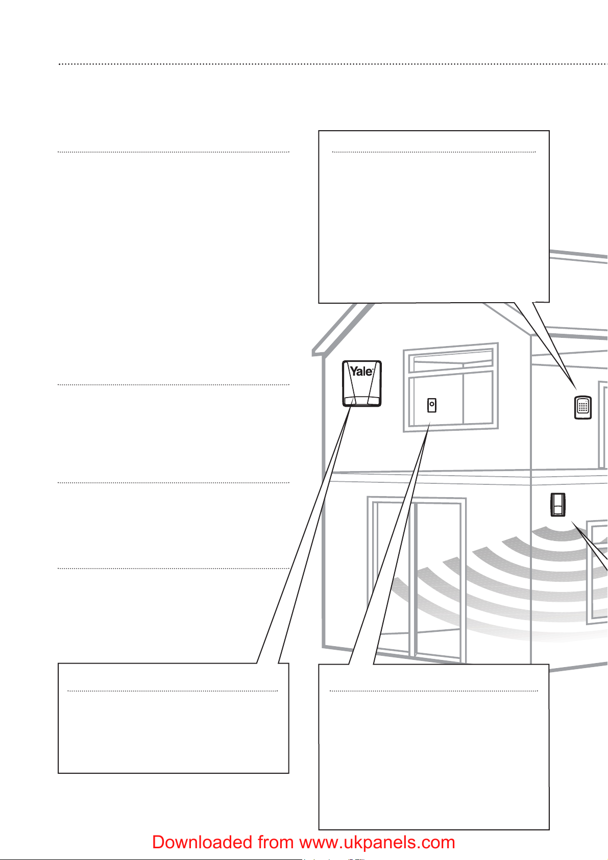
Location planning
Work out the best places to locate the devices for maximum protection. Having chosen
the locations do not mount at this stage.
4
1
Keypad remote control accessory
When used as second keypad, it is ideal
in bedrooms or at the top of a stairwell so
the ground floor can be armed when going
to bed for the night. Or, at a side or back
door for alternative entry.
• Mount at chest height for ease of use
• Designed for indoor use only
• Keypad should be accessible from a
protected entry/exit point
• Ensure that the keypad is not visible from
the outside of the premises.
Home and away mode planning
The home arming mode allows the premises to
be part armed so that no one can get inside
without warning the occupier, yet the person
already inside the house can move freely without
triggering the alarm. For example the downstairs
of a house can be armed while upstairs can be
disarmed allowing the user to go to bed without
causing an alarm.
If this feature is to be used, then it should
be planned now, before installation.
Decide what areas can be occupied when in
home arming mode, the sensors for these areas
should be programmed to home omit; and the
sensors activated on the path to access the
control unit should be to be set to home delay as
explained in ‘Further programming’ (page 16).
Operating range
All devices must be within 30 metres of the
control unit and must not be mounted on or near
large metal objects. Avoid obvious sources of
electrical interference such as fridges and
microwave ovens.
Tamper switches
When mounting devices ensure that any
tamper switches close fully. On uneven surfaces it
may be necessary to place packing behind the
switch for reliable operation.
Extend the system
Extend the system in the future to increase
your security or as your needs change.
For example, add extra PIR detectors and
extra door/window contacts.
Help button accessory
The help button provides extra protection
for you and your family. When help is needed
the button can activate your alarm
immediately - even when the system is
disarmed.
• Mount on bedroom wall or by the front
door
• Not clearly visible to an intruder
• Easily accessible
• Out of reach of children
Dummy siren
Choose a secondary position on another
external wall where the siren would be most
prominent. Mount as high as possible, out of
easy reach.
Downloaded from www.ukpanels.com
Page 5
5
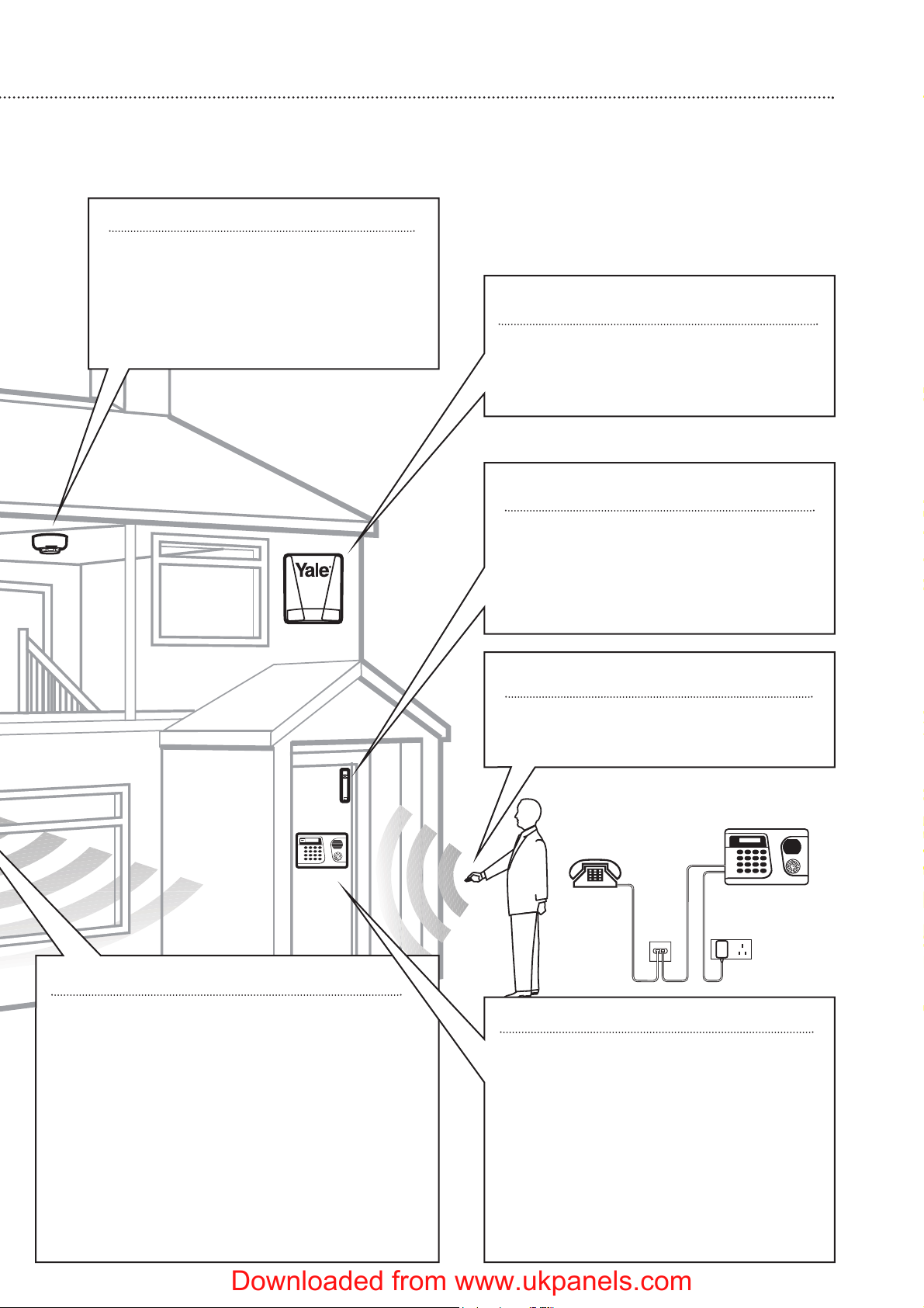
Smoke detector accessory
• Mount on the ceiling at the top of a
stairwell, or where smoke would most
likely be detected.
• Install additional detectors if there are
closed doors preventing smoke from
reaching detectors.
PIR movement detector
• Mount in a position such that an intruder would
normally move across the PIRs field of view.
• Height should be between 1.7 and 2.3 metres above
floor level.
• Location in a corner will ensure wider room
coverage.
• Do not mount the PIR where its field of view will be
obstructed e.g. by curtains, ornaments etc.
• Do not point directly at sources of heat e.g. fires or
boilers, and do not position directly above radiators.
•Avoid mounting the PIR directly facing a window.
• Do not point the PIR at a door protected by a
door/window contact.
Keyfob remote control accessory
Can be used inside or outside the
property and can be kept on your keyring.
Door/Window contact
Select a door that will be the main point
of entry and exit, usually your front door.
• Mount as high as possible
• Do not aim a PIR at this door or window
Siren
Choose a position on an external wall
where the siren would be most prominent.
Mount as high as possible, out of easy reach.
Control unit
• Ensure the control unit is accessible when
entering through a protected entry/exit
point.
•Avoid mounting the control unit where it
would be visible from the outside of the
premises
• Locate by a mains socket and telephone
point.
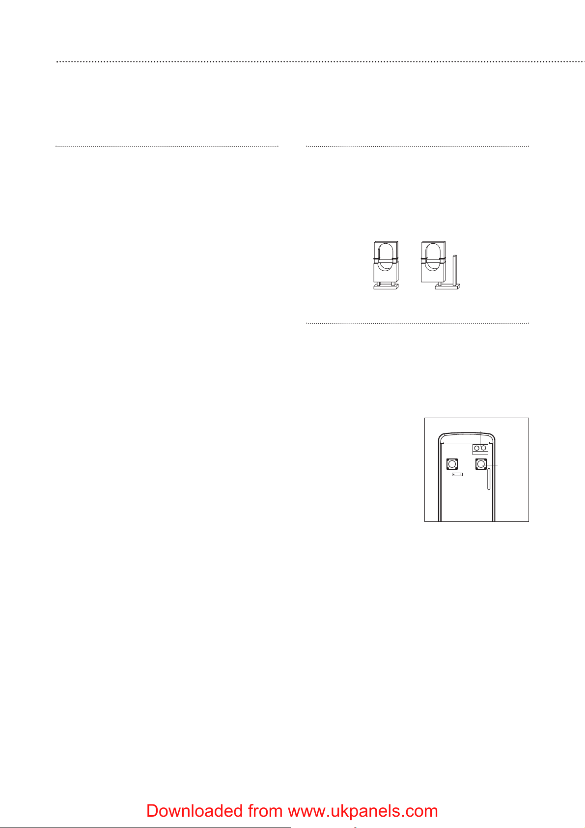
The supplied base unit gives provision for
the control unit to be placed on a table top
or wall mounted.
Downloaded from www.ukpanels.com
Page 6
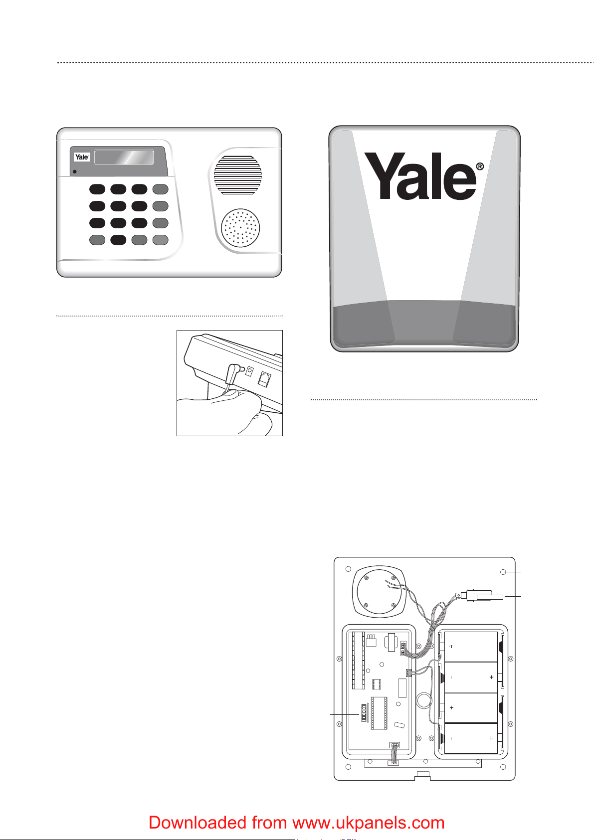
Control unit
Plug the power adaptor
into the mains supply wall
socket and the other end
into the control unit.
• The batteries in the
control unit are
rechargeable and act as
a back-up in case of
power failure. They are
charged automatically
by the mains supply. If the mains supply is
disconnected, an AC Power Fail message will
be displayed and the LCD back light will be
switched off.
•From new, the batteries need 72 hours to
charge completely.
6
Unpack all the parts onto a table top
The easiest way to get to know the system and get it up and running quickly is to get
all the devices and accessories programmed on a table top before locating and mounting them.
2
Siren
WARNING: The siren is very loud, be
prepared! Take care not to activate the siren
unnecessarily.
1 Remove the cover by unscrewing the single
screw located at the bottom.
2 Remove the covers of the two internal
compartments.
3 Insert the four D batteries as shown.
There is a slight pause while the unit initialises.
The siren will then beep and the LEDs flash.
Tamper
switch
Jumper
switches
Fixing holes
x 4
Downloaded from www.ukpanels.com
Page 7
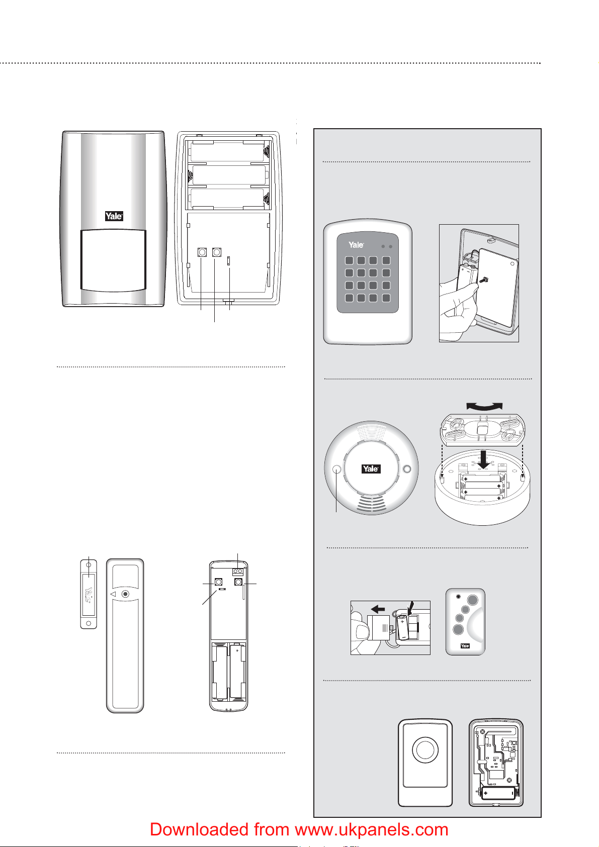
PIR movement detector
Remove the fixing screw and cover assembly
and insert the three AA batteries as shown.
• The light steadily flashes for 30 seconds while
components initialise.
Door/window contact
1 Remove the cover by loosening the fixing
screw.
2 Insert the two AAA batteries as shown. The
indicator will flash briefly.
7
+
+
+
3
A
b
Keypad remote control accessory
Remove the cover and insert the PP3
battery as shown. The ‘Tx’ LED will flash
briefly while components initialise.
Smoke detector accessory
Remove the cover and insert the four AAA
batteries as shown.
Keyfob remote control accessory
Slide off the battery cover, insert the
23A/MN21 battery as shown, and replace
cover. Switch to ‘on’.
Tamper
switch
Jumper switch
Learn/Test button
Tamper
switch
Jumper
switch
Extension terminalsMagnet
Learn/Test
button
Learn/Test button
Help button accessory
Remove the cover by loosening the fixing
screw and insert the 12V battery (supplied) as
shown. Please
ensure you
observe
battery
polarity.
Downloaded from www.ukpanels.com
Page 8
Use of jumper switches
Some devices have internal switches, or
‘jumpers’, which control working modes, or offer
additional programming. The jumpers are either
‘on’ or ‘off’. ‘On’ is when the jumper connects
two pins, ‘off’ when it is removed. It can be
‘parked’ on one pin as shown.
Add the door/window contact
1 Press c (program key), enter your PIN code and
press OK.
2 Select ‘Devices +/-‘ by scrolling down the
program menu and press OK.
3 Select ‘Add Devices’ and press OK.
• Display will show ‘Push Button On Device to
Add’.
4 Press the learn/test
button in the rear of
the door/window
contact.
• The control unit will
show it has detected
the device by
displaying ‘Detected:
(Ok?) Door Contact’.
5 Press OK.
6 You are prompted to select a zone. The control
unit displays all the zones available (zones
where no device has been added), with the
cursor flashing at the first free zone (in this
instance zone 1), press OK.
• Each device is given a zone number so that the
control unit can indicate the source of an alarm.
• Door/window contacts can be used in various
applications to suit your needs, eg home omit
(see ‘Further door/window contact
programming’ page 16). As most systems
require a detector on the point of entry, for this
example the door/window contact is
programmed as an entry detector. When used
as an entry detector, with the system armed
the door/window contact will start an entry
countdown upon activation, giving you time to
disarm the system.
7 Select ‘Entry’ from the list displayed and press
OK.
8 The display now shows the selected settings:
DC Zone01 E – door/window contact
3
8
Easy install programming
First, create your own PIN code and teach the control unit to recognise (learn) all the
devices and get the basic system up and running.Do not mount at this stage.
Control unit
When power is connected, a long beep will
sound. ‘Alarm On’ will be displayed. This indicates
that the system is armed.
Before you can deactivate the alarm, or enter
any information into the system, you must enter a
PIN code. This is factory set to 0000.
Disarm
1 Key 0, Enter Code is displayed.
2 Key in 000 to complete the factory set code.
3 Press OK. You will hear 2 short beeps and the
display will show ‘Alarm Off’, and the default
time and date.
The system is now disarmed.
• If no code has been entered for a while, the
display will revert back to the original screen.
Introduction to programming
Entering a new PIN code will introduce you to
the ease of programming the system.
Set your PIN code
1 Press c (program key).
2 Enter 0000.
3 Press OK.
‘Program menu/Make a Selection’ appears
briefly, which is then replaced by a list which can
be scrolled up and down using the arrow keys.
The action to be selected has a pulsing symbol
alongside.
4 Use the down arrow key to select ‘General
Settings’.
5 Press OK to select this sub-menu.
The first item in this list is ‘Pin Code’ which we
require.
6 Press OK.
7 The system asks you for a new PIN code. Think
of one all the family can remember and key it
in. Don’t forget it, write it in ‘System records’
page 14.
8 Press OK.
9 Confirm by keying in your PIN code again.
10 Press OK. If the incorrect code is entered, a
message prompts the previous step.
Most programming functions work in this way,
by entering your code, selecting from menus and
sub-menus and responding to the prompts.
• During entering the PIN code press the a
button to clear the screen and enter new
information.
•Press a to return to a previous menu.
•To return to ‘Alarm off’ in normal mode, keep
pressing a repeatedly.
Jumper in
‘off’ ‘parked’
position
Jumper in
‘on’
position
Learn/
Test
button
Extension terminals
Downloaded from www.ukpanels.com
Page 9
9
programmed into zone 1 as an entry point
detector.
9 Press OK.
•Press a to return to previous menu.
•To return to ‘Alarm off’ (normal mode), press a
repeatedly.
Add the PIR movement detector
1 Select ‘Devices +/-‘ by scrolling down the
Programming menu and press OK.
2 Select ‘Add Devices’ and press OK.
3 Press the learn/test button the rear of the PIR.
• The control unit will show it has detected the
device by displaying
‘Detected: (Ok?) PIR
sensor’.
4 Press OK.
5 You are prompted to
select a zone. The
cursor will flash at the
next available zone (in
this instance zone 2),
press OK.
• As with the
door/window contact, PIRs can be used in
various applications to suit your needs (see
‘Further programming’ page 16). For this
example the PIR is programmed as a ‘Burglar’
detector. When used as a burglar detector,
when the system is armed and the PIR
activated, the alarm will sound instantly.
6 Select ‘Burglar’ from the list displayed and
press OK.
7 The display now shows the selected settings:
PIR Zone02 B – PIR programmed into zone 2 as
a burglar detector.
8 Press OK.
9 Press a repeatedly until display shows ‘Alarm
Off’.
Add the siren unit
WARNING
The siren is very
loud, be prepared! Take
care not to activate the
siren tamper switch
unnecessarily.
The siren is
programmed by the
jumper switches in the
left hand compartment.
1 Lift off jumper number 1 and park it. The siren
will beep and flash. The siren is now in learn
mode.
2 Lift off jumper 5 and park it. This must be left in
the ‘off’ position permanently.
• If jumper 3 and jumper 4 are removed during
the learning-in process, the siren will only be
activated for 1 second if accidently activated
and is useful for testing. Ensure the jumpers
are placed into the positions desired before
replacing the cover.
3 Program the control unit by selecting ‘Devices
+/-’ menu, then ‘Program Siren’ menu, then
‘Learn Siren’.
4 Press OK and the unit will give a long beep to
confirm - the siren will also respond by a beep
and a flash.
5 Replace jumper 1 to the on position, the siren
will beep and flash to confirm.
6 To ensure siren does not activate, disable the
tamper switch by selecting ‘Program Siren’
menu on the control unit, then ‘Siren A/T Off’,
and press OK.
• The siren disable tamper will automatically
revert to on after about an hour if not switched
back on again manually by selecting ‘Siren A/T
On’.
•Press a to return to a previous menu.
•To return to ‘Alarm off’ in normal mode, keep
pressing a repeatedly.
Further siren programming
The siren can be configured to your personal
requirements by the use of jumpers.
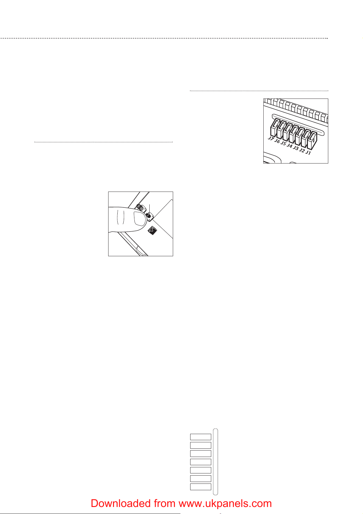
Siren jumper programming
Learn/Test
button
Downloaded from www.ukpanels.com
J7
J6
J5
J4
J3
J2
J1
Jamming detection
Clear memory (leave On)
Slave mode (leave Off)
Siren activation time
Siren activation time
Strobe activation mode
Learning-in mode (leave On)
Page 10

10
Jumper positions
J7 on = jamming detection ‘off’;
off = jamming detection ‘on’
J6 on = normal, J6 off = clear memory
J5 on = stand alone operation, not used in
this system;
off = slave operation
J3 on, J4 on = 3 minute siren ‘on’ period
J3 off, J4 on = 5 minute siren ‘on’ period
J3 on, J4 off = 10 minute siren ‘on’ period
J3 off, J4 off = 1 second siren ‘on’ test
period
J2 on = LEDs ‘on’ during siren period;
off = LEDs remain ‘on’ (after an alarm)
until system is disarmed
J1 on = normal; off = learn-in mode
• Jumper 5 must be left in the ‘off’ position.
• J6 must be left ‘on’ in normal service
otherwise the siren will lose its learn-in
memory when the batteries are replaced.
•With J7 ‘off’, jamming by radio interference is
detected when continuously present for more
than 30 seconds and activates the siren only
when armed.
• If jumper 3 and jumper 4 are removed during
the learning-in process, the siren will sound for
1 second and is useful for testing. Ensure they
are replaced in your chosen positions before
replacing the covers.
7 Replace the battery and electronics
compartment covers, ensuring the gasket
between the electronics compartment and
cover is correctly located and the wires placed
in their slots to ensure a good seal from the
environment.
Tamper alarm
If the siren detects a tamper condition it will
activate the siren for the programmed period. If
the tamper condition persists the siren will sound
a series of five pips either every time the system
is armed or when the tamper is enabled, to
indicate the condition.
Confirm Programming
The siren can be programmed to produce
additional confirmation beeps to tell you when the
system is armed and disarmed from outside the
premises. One beep for armed or home armed,
two beeps for disarmed.
1 Program the control unit by selecting ‘Device
+/- menu’, then ‘Program Siren’ menu, then
‘Confirm On’.
2 Press OK and the unit will give a long beep to
confirm - the siren will also respond with a
beep.
Radio jamming
This control unit and siren are equipped with
the latest type of radio receiver using AM radio
technology. If interference detection is set to ‘on’
in the siren, when the system is armed, any
criminal attempt to prevent (or jam) the detector
transmissions will be picked up as interference
and will cause the siren to alarm. The control unit
can be set to display or report (by dialling out, not
sounding alarm) when interference is detected.
If the alarm is frequently triggered by
interference there may be high levels of unusual
radio signals in your area. Some kinds of
electronic equipment can generate this kind of
radio interference.
In the unlikely event of you experiencing
problems with interference, it is recommended
that you switch jamming detection off.
Please telephone our helpline if you require any
further assistance.
Downloaded from www.ukpanels.com
Page 11

11
Installation/mounting
WARNING To prevent the alarm from activating during installation, the siren must have
its tamper disabled and the control unit must be in ‘Walk Test’ mode.
4
Testing the radio performance
Before permanently installing the system,
check that the siren will receive the system radio
transmissions by doing a simple radio range test.
1 Ensure that the siren tamper is disabled.
2 Mount the siren temporarily in the location you
have chosen.
• Use either a masonry nail or single screw in the
siren base keyhole to temporarily fix in place.
3 Put the control unit in the chosen position and
arm and disarm as described in ‘Using the
system’ (page 13), and check that the siren
responds.
4 Put the control into ‘Walk Test’ mode, as
described in ‘Testing the system’ (page 17),
steps 1-3. Hold the devices in the chosen
locations and activate.
• The PIR and door/window contact can be
tested by pressing the learn/test button.
• Please be aware of the PIR sleep timer (see
page 12).
5 When you are satisfied that the devices work in
their chosen locations, proceed with the
installation as described next.
• If the device does not respond, the location
may be out of radio range, try alternative
locations until reliable radio contact is obtained.
Mounting methods
Yale provide two methods of mounting. Choose
either the self adhesive pads or the screws and
wall plugs supplied.
Self adhesive installation for door/window contact
Clean the surface with a suitable degreaser.
Remove the protective covering from one side of
the double sided adhesive pad and firmly apply to
the back of the device. Next remove the other
cover and firmly press the item onto the desired
location.
• Do not use the adhesive pad method of
installation on a surface with peeling or cracked
paint, or on a rough surface.
Screw mounting
Remove the front of the device, and, if
necessary, break through the appropriate knockout
(where the plastic is thinner).
Using the holes as a template, drill holes in the
surface and insert the wall plugs if fixing into
plaster or brick.
Siren
WARNING: The siren is
extremely loud!
The tamper switch
plunger protrudes through
the back of the unit, so
that if the siren is pulled
from the wall the alarm is
activated. Ensure it is fully
depressed when the siren
is mounted. If there is a
gap, pack with a suitable
spacing material.
1 Find suitable location,
as previously described in section 2.
2 Disable the tamper switch by selecting
‘Program Siren’ menu on the control unit, then
‘Siren A/T Off’, and press OK.
3 Using the large screws
provided, mount on
wall through the base
plate mounting holes
shown.
4 Fix the siren cover
with the securing
screw.
5 Enable tamper switch
by selecting ‘Program
Siren’ menu on the
control unit, then
‘Siren A/T On’, and press OK.
6 Test by arming and disarming with the control
unit. If 5 pips sound the tamper is not correctly
set.
Control unit
Table top
Place the mounting
base on the back of the
control unit and snap in
place so that the unit is
angled towards you.
Wall mounting
Fix the bracket to the
wall as described in
‘Mounting methods’. Snap
the mounting base so that
the control unit is angled
upwards, as shown.
Hang the control unit
on the bracket.
Bracket
Mounting base
Tamper switch plunger
must be pressed in fully by
wall surface
Fixing holes x 4
Downloaded from www.ukpanels.com
Page 12

12
PIR movement detector
The PIR has a built-in sleep timer to save
battery power. If there is no movement in front of
the PIR for 1 minute, the PIR will become ‘ready
to signal’ and any movement will now be
reported. The PIR will sleep for 1 minute after.
Any movement detected in sleep time will not be
reported and will extend the sleep period by 1
minute.
Ensure the test/normal mode jumper switch is
in the test ’on’ position. This reduces the sleep
time to a few seconds and enables the LED to
flash every time movement is detected.
1 Screw the rear case to the wall
using the appropriate
knockouts, as described in
‘Mounting methods’. The case
has angled back edges for neat
corner mounting. If mounting
in a corner take care not to
bend the rear case. Screw the
PIR front on.
2 Walk around the protected area
noting when the LED flashes
and check that the detection
coverage is adequate.
• Remember to wait a few seconds after the PIR
has detected movement.
• Do not try to test the detection pattern by
walking straight up to, or away from the
detector, walk across the field of view.
3 When you are satisfied with the detection
coverage, remove the PIR, place the jumper in
the normal ’off’ parked position and screw the
PIR back on to its case.
•With the jumper in the normal position the LED
will not normally light unless there is a problem,
either a low battery or a tamper condition. In
the event of a low battery, replace the
exhausted batteries with fresh alkaline
replacements.
• Do not position a PIR to look directly at a door
protected by a door contact, this could cause
the door contact and PIR radio signals to be
transmitted at the same instant when entering,
cancelling each other out.
• Ensure the jumper is in the normal ‘off’ position
when testing is finished, otherwise low battery
and tamper conditions will not be shown.
Door/Window contact
1 Ensure the jumper switch is in the test ‘on’
position.
• In this position the indicator light will illuminate
every time the door contact is operated.
2 Fit as described in
‘Mounting methods’,
mounting the
detector base on the
frame and aligning
the magnet by the
arrow as shown.
• The magnet should
not be more than
8mm from the
detector when the
door is closed.
• Ensure the tamper
switch spring is
positioned so that it
makes contact with
the mounting surface through the tamper
switch aperture.
• If the door contact cannot be mounted on the
door frame, use the HSA3090 multiple
door/window contact accessory kit with a
length of wire to mount the door contact
remotely (see page 17).
• When fitting to a window, fix the magnet to the
moving part and the detector to the frame.
3 Fix the detector on its base and secure with
screw. Test it by opening and closing the door
or window. The light will flash when an open
condition is detected.
4 Remove the detector, put the jumper switch in
the normal ‘off’ position. Screw the detector
back onto its base.
• When the jumper is in the normal ‘off’ position
the indicator light will normally be off. It will
only light if there is a problem, either a low
battery or a tamper condition.
• Ensure the jumper is in the normal ‘off’ position
when testing is finished, otherwise low battery
and tamper conditions will not be shown.
Dummy siren
1 Find a suitable location as previously described.
2 Screw to wall as described for Siren, points 3
and 4.
Installation is complete.
Door/
Window
Frame
Align
8mm (max)
Corner fixing
holes x 4
Surface fixing
holes x 2
Downloaded from www.ukpanels.com
Page 13

13
Arming the system
Full arming
1 Enter your PIN code and press OK.
2 Arm and Home can be selected by using the
arrow keys, select ‘Arm’.
3 Press OK. The exit delay is displayed and
counts down from the default setting of 10
seconds. The control unit beeps (unless exit
sound has been switched off).
4 When the time is up, the control unit sounds a
long beep. ‘Alarm On’ is displayed and the
system is armed.
• The siren will beep once (if siren confirm has
been switched on), and the strobe will flash
once after the Exit Delay has expired.
Home arming
1 Enter your PIN code and press OK.
•You have a silent exit period in which to vacate
the armed area. This exit period is the same as
used when fully arming.
2 Press ▼ to move the cursor down to select
Home.
3 Press OK.
•You can also put the system into the home
mode by using the keypad or keyfob accessory.
Stopping the exit delay
Do this by disarming the system.
1 Press a.
2 Enter the PIN code.
3 Press OK.
’Alarm Off’ will be displayed and the system
returns to disarmed mode.
Disarming the system
1 Enter your pin code.
2 Press OK. The control unit will sound 2 short
beeps and disarm.
• The siren will beep twice (If siren confirm has
been switched on) and the strobe will flash
from side to side after the system has been
disarmed.
Alarm activation
If a sensor is triggered when armed, or if an
entry period is left to expire, the control unit will
activate the alarm immediately, while if a Home
Omit sensor is triggered, the control unit will not
respond if in home mode.
If a 24-hour alarm, fire alarm, personal attack,
alarm tamper or medical emergency is triggered,
the control unit will activate the alarm
immediately irrespective of what armed mode the
control unit is in.
During an alarm, the control unit will sound the
siren and start to dial the programmed phone
numbers.
If a tamper alarm is activated when the panel is
disarmed the system will not dial out.
Stopping the alarm
1 Key in your PIN code, and then press OK.
The alarm and dialling will stop and the display
will show the device and zone which triggered
the alarm in the Alarm Log.
2 Press any key.
The display will show the telephone call made
if successful.
3 Press any key again to see if the second call
was successful (if programmed).
If nobody has answered the call or only one
recipient has answered the call, the screen will
return to ‘Alarm Off’.
When the log has been displayed the screen
will return to ‘Alarm Off’.
If an alarm is silenced using a remote keypad
or keyfob, the system will only silence the alarm not disarm the system. The system can only be
disarmed after an alarm event at the control
panel.
Alarm memory
If an alarm was raised during your absence,
and the alarm sequence has been carried out, the
screen will continue to show ALARM!
When you come back and disarm the system
the siren will sound a 3-second alarm instead of
the normal 2-beep sound.
To clear the display, follow the same steps as
stopping the alarm described above.
Warning If the siren is activated for 3-seconds
when you disarm your system there could be an
intruder still in your premises.
Using the system
Arm and disarm the system and practice using it. Trigger the alarm by arming the system
and opening protected doors/windows and walking past PIR’s. Now is the time to show
the rest of the family how simple it is to use. The telephone features are yet to be
programmed.
5
Downloaded from www.ukpanels.com
Page 14

14
Tamper display
The control unit will identify the device
triggering a tamper alarm when the system is
disarmed. To enable the display to be cleared a
tamper condition has to be rectified. For example,
if a detector has been tampered the display can
only be cleared once the detector tamper has
been closed. The display is cleared by entering
your PIN code, pressing OK, and exiting the ‘Arm
Home’ display by pressing a.
Please note that detector tampers will trigger
an alarm even when the system is disarmed. If
you wish to take down a detector that has tamper
protection ensure the control unit is in ‘Walk Test’
mode.
Low battery display
When a detectors batteries are running low, it
will signal its condition to the control unit when it
is activated. To be able to clear the display the
batteries in the detector will have to be changed.
Always use alkaline batteries as replacements and
ensure the control unit is in ‘Walk Test’ when
taking down detectors. After changing batteries,
once the detector is activated (out of ‘Walk Test’
mode), the display can be cleared as described in
‘Tamper display’.
System records
For your future convenience, record your system settings below. For your security please
keep this information confidential.
My PIN code
Zone no. Location Type
1
2
3
4
5
6
7
8
9
10
11
12
13
14
15
16
17
18
19
20
Downloaded from www.ukpanels.com
Page 15

15
Configuring your system
Fine tune the operation of the control panel to your requirements; advanced
programming for PIRs and door/window contacts.
General settings menu
Pin code
To change PIN code, follow steps in ‘Easy
install programming’.
Entry time
Enables you to alter the entry delay time.
Options available are 0 sec., 10 sec., 20 sec., up
to 70 sec. in 10-sec increments.
1 Use the arrow keys to switch between options.
2 Press OK to confirm.
• 10 sec. is set as factory default.
• Entry delay time applies only to the zone that a
door contact or PIR is installed and is set to
entry point.
Exit time
Enables you to alter the exit delay time.
Options available are 0 sec., 10 sec., 20 sec. up to
70 sec. in 10-sec increments.
1 Use arrow keys to switch between options.
2 Press OK to confirm.
• 10 sec. is set as factory default.
Alarm length
This is for you to select the period of time that
the control unit siren will sound when an alarm is
activated. You can choose from 1 minute to 15
minutes in 1 min increments.
1 Use arrow keys to switch between options.
2 Press OK to confirm.
•3 minutes is set as factory default.
Control unit siren on/off
Enables you to set the control unit siren (not
external siren) to be silent in the event of an
alarm.
1 Press arrow keys to select the option.
2 Press OK to confirm.
• Siren ON is set as factory default.
• It is recommended that the control unit siren is
left on.
Exit sound
Switches on and off the exit countdown beeps.
1 Press arrow keys to select the option.
2 Press OK to confirm
• Exit Snd Low is set as factory default.
• The exit sound can be selected for high or low
volume.
Entry sound
Switches on and off the entry countdown
beeps.
1 Press arrow keys to select the option.
2 Press OK to confirm.
• Entry Snd Low is set as factory default.
• The entry sound can be selected for high or low
volume.
Door chime
Switches on and off the door chime in the
control unit when an entry sensor is activated.
1 Press arrow keys to select the option.
2 Press OK to confirm.
• Door Chime Off is set as factory default.
• The door chime can be selected for high or low
volume.
Listen-in
Switches on and off the listen-in feature if
privacy is required.
1 Press arrow keys to select the option.
2 Press OK to confirm.
• Listen-in On is set as factory default.
• It will not be possible to remotely listen-in or
listen-in on an alarm situation when this feature
is turned off.
Time
Allows you to set the current time (hours and
minutes).
1 Hours will flash, use arrow keys to select the
hour, 24-hour format is used.
2 Press OK to confirm the hour setting.
3 Now the minutes will flash, use arrow keys to
select the minutes.
4 Press OK to confirm.
•Time will have to be reset if all power to the
unit is lost.
Date
Allows you to set the current date.
1 Months will flash, use arrow keys to select the
month.
2 Press OK to confirm the month setting.
3 Now the day will flash, use arrow keys to select
the day.
4 Press OK to confirm.
• Date will be reset if all power to the unit is lost.
Interference
Allows you to set the control unit to respond to
the presence of radio jamming.
1 Use arrow keys to choose the setting.
2 Press OK to confirm the setting.
• ‘Disp Off’ is set as factory default.
• ‘Disp On’ will enable the display of any
interference that is detected for more than 30
Downloaded from www.ukpanels.com
Page 16

16
seconds when the control unit is disarmed.
•With interference set to ‘Disp and Rep On’,
when the system is armed (fully armed, not
home armed) and interference is detected, the
control unit will notify of the presence by
dialling out. Interference will not cause the
control unit to sound in alarm.
• Radio interference is unlikely, but can affect the
operation of the system. Please read ‘Radio
jamming’ (page 10) for more information.
• The control unit and the external siren both
have independent radio interference detection.
It is possible for the siren to detect and respond
to interference (if set), even if the control unit
does not detect any radio interference.
Keyfob remote control entry enable
Turns on and off the remote control disarm
function.
1 Press arrow keys to select the option.
2 Press OK to confirm.
• Remote Control Entry Enable off is set as
factory default.
• When the keyfob remote entry enable is set to
‘off’ it will not be possible to disarm the control
unit when the system is fully armed unless an
entry point device is activated first. This feature
is used to ensure that the system cannot be
disarmed with a stolen remote control without
unlocking a door first.
• When the keyfob remote control entry enable is
set to ‘on’, the keyfob remote can arm and
disarm the control unit as normal without
activating an entry point first.
•A panic alarm cannot be disarmed by a keyfob
remote. This prevents an assailant from
silencing a personal attack alarm by snatching
the keyfob and pressing Disarm.
Further PIR programming
The PIR can be used in four different ways
within the system:
•To cause an instant alarm upon detection when
the system is fully or home armed;
•To be omitted when the system is home
armed;
•To commence an entry countdown upon
detection when the system is home armed, but
cause an instant alarm when fully armed;
•To commence an entry countdown upon
detection when the system is fully or home
armed.
These choices are presented during the
learning in process and are summarised by the
following codes within the control unit:
B Burglar active when control unit is
in armed or home mode
O home Omit not active when in home
mode
D home Delay starts entry countdown
when in home mode
E Entry starts entry countdown
when in armed or home
mode
PIR operation
The LED does not normally flash when it
senses movement. This is to conserve battery
power.
If the LED flashes regularly, it indicates that it
has either been tampered with, or the batteries
are getting low and need replacing.
Further door/window contact programming
The door/window contact can be used in six
different ways within the system:
•To cause an instant alarm upon activation when
the system is fully or home armed;
•To be omitted when the system is home
armed;
•To commence an entry countdown upon
activation when the system is home armed, but
cause an instant alarm when fully armed;
•To cause a fire alarm when activated whether
the system is armed or disarmed;
•To cause an instant alarm whether the system
is armed or disarmed (24-hour alarm);
•To commence an entry countdown upon
activation when the system is fully or home
armed.
These choices are presented during the
learning in process and are summarised by the
following codes within the control unit:
B Burglar active when control unit is
armed or home mode
O home Omit not active when in home
mode
D home Delay starts entry countdown
when in home mode
F Fire causes fire alarm upon
activation whether system
armed or disarmed
H 24 Hour causes burglar alarm upon
activation whether system
armed or disarmed
E Entry starts entry countdown
when in armed or home
mode
Downloaded from www.ukpanels.com
Page 17

HSA3090 multiple door/window contact set
should be used (not included).
The magnet/contact pairs are wired using bell
wire (not supplied) to the extension terminals as
indicated on page 7. The knockout in the top of
the door/window contact must be removed to
allow the wire to pass through. The total length of
wire used must not exceed 10 metres. The
magnet/contact pairs should be no further than
8mm apart.
It is possible to use a single pair of multiple
door/window contacts with a detector if you
experience problems fitting the main unit to the
door frame.
When using multiple switches on a
door/window contact, you can use the detector
without having a magnet alongside the main unit.
17
Points for consideration
• In home mode, detectors set as ‘Burglar’ will
cause an alarm when activated, whilst
detectors set as ‘Home Omit’ will not trigger
an alarm.
• If the system is fully or home armed, detectors
set as ‘Entry’ will start the entry countdown
when activated. When disarmed, an entry
detector will sound a ‘ding-dong’ chime from
the control unit (if ‘door chime’ is selected).
• If a detector is set as ‘Home Delay’ it will start
an entry countdown when the system is home
armed. This setting is useful if your path to the
control unit (when used at night) is vulnerable
(a stairwell for instance).
• After testing the door/window contact and PIR
in your chosen locations, please ensure that
the jumpers are moved into the ‘off’ (parked)
positions. If left in the ‘on’ positions battery life
will be shortened and it will not be apparent if
the detector has a tamper or low battery
condition.
Multiple door/window contact wiring
If difficulty is experienced fitting the
door/window contact because of space etc, the
PIR sleep feature
The PIR has a built-in sleep timer to save
battery power. If there is no movement in front of
the PIR for 1 minute, the PIR will become ‘ready
to signal’ and movement will now be reported.
The PIR will sleep for 1 minute after. Any
movement detected in sleep time will not be
reported and will extend the sleep period by 1
minute.
Walk test
This allows you to test the system without
causing an alarm.
1 Press c followed by your PIN code.
2 Press OK.
3 Select ‘Walk Test’.
4 Walk around protected areas in front of PIR’s
and open doors/windows protected by door
contacts.
• If the control unit receives a signal, it will sound
a chime and the display will show the sensor
and zone number which has been tested.
• The message will be displayed until being
replaced by another test signal.
•Pressing the a key, will return to programming
menu.
• If left in walk test, the control unit will revert
back to ‘Alarm off’ after 20 minutes.
Testing the siren
The siren can be tested by arming and
disarming the system, the siren will respond as
follows:
• When the control unit is armed the siren will
beep once (if siren confirm is switched on) and
will flash after the Exit delay period has expired.
• When the control unit is disarmed, the siren will
give two short beeps (if siren confirm is
switched on) and will flash from side to side
twice.
Knockout
removed for
wire
Door/window
switches wired
in series
Magnets
Testing the system
Testing the system should be done on a regular basis and after any alterations.
Downloaded from www.ukpanels.com
Page 18

18
Keyfob remote control accessory
Programming
Learn in the keyfob as follows:
1 Enter the ‘Devices +/-‘ menu and select the
‘Add Device’ sub menu.
2 Press the Arm button on the keyfob remote
when prompted.
3 After you have assigned a zone number for the
keyfob remote, you are presented with a
choice:
• ‘Medical Emg’: Control unit dials a medical
emergency alarm when the Panic button on the
keyfob remote is pressed; or
• ‘Personal Att’: Control unit dials a personal
attack alarm when the Panic button is pressed.
4 After making your selection, the display will
show the successfully installed device.
5 Press OK.
• The Panic button has to be pressed for more
than 5 seconds to operate. This is a safety
feature to stop accidental operation.
• If programmed as a Personal Attack alarm, an
alarm started by the Panic button cannot be
silenced with the keyfob remote, only with the
control unit. This is a safety feature to stop any
potential attacker disarming the system after a
Personal Attack alarm has started.
Using
The system is armed by pressing the Arm or
Home button for at least 1 second (this delay
feature prevents accidental operation).
The system is disarmed by pressing the Disarm
button in the same way.
The switch at the side prevents the keyfob
from transmitting accidentally.
• The keyfob can also be used to answer an
incoming telephone call by pressing the Disarm
button twice for 1 second with a pause
between and then to close the call by pressing
the Disarm button again for 1 second.
• When arming the system in ‘home’ mode using
the keyfob remote, the system will arm and
disarm instantly without an exit or entry
countdown.
Keypad remote control accessory
Programming
1 Enter the ‘Devices +/-‘ menu and select the
‘Add Device’ sub menu.
2 When prompted by the control unit enter 0000
on the keypad then press TEST. The ‘Tx’ LED
will flash showing that the keypad is in program
mode.
3 Press TEST then 1 on the keypad. The keypad
and the control unit will beep.
4 After you have assigned a zone to the keypad,
the display will show the successfully installed
device.
5 Press OK on the control unit.
6 Press Off twice on the keypad to exit program
mode, Tx LED will stop flashing.
• The keypad will beep every 30 seconds if the
tamper switch is open. Please ensure tamper
switch closes when mounting.
Changing PIN number
1 Put the keypad into programming mode by
entering the factory set code 0000 and pressing
TEST.
2 Enter 0000 then press CLR.
3 Enter your new 4 digit code then press PROG.
The keypad will beep in response.
4 Press OFF twice to exit programming mode.
• It is advisable to use the same PIN code as the
control unit, but it can be different.
Using
To arm the system:
Enter your PIN code and press Arm.
To disarm the system:
Enter your PIN code and press Off.
To home arm the system:
Enter your PIN code and press Home.
Adding accessories
To provide additional protection you can add extra door/window contacts, PIRs, keyfob
remote controls, keypad remote controls, help buttons and smoke detectors. These are
available separately from your local stockist.
Downloaded from www.ukpanels.com
Page 19

19
Help button accessory
Program your help button before installation
and test in the desired location before mounting.
Programming
1 Follow sections 1 and 3 (Inserting batteries and
Location planning).
2 With the system in learn mode, press and hold
the red button on the help button – the LED will
light momentarily and your system will confirm
the transmission.
3 Take your system out of learn mode.
• The help button can be tested by entering learn
mode (see user guide) and activating the help
button. The siren will beep in response to the
activation. Please ensure you exit learn mode
after testing.
Using
To activate, press and hold the red button for at
least 2 seconds – LED will light momentarily and
the alarm will be activated.
To silence an alarm, press and hold down the
red button, after 10 seconds the LED will light
momentarily for a second time – alarm will be
silenced
• Please note that silencing the alarm with the
help button does not reset the system. If the
alarm is armed prior to activation, the system
will re-arm after being silenced with the help
button.
Smoke detector accessory
Programming
1 Enter the ‘Devices +/-‘ menu and select the
‘Add Device’ sub menu.
2 When prompted by the control unit, press the
learn test button on the smoke detector.
3 Assign a zone number to the smoke detector.
4 Press OK to confirm.
• The smoke detector will indicate a fire by
sounding the built-in siren, lighting the LED, and
signalling the system to alarm.
• The smoke detector will produce a warning
beep and the LED will flash every 30 seconds if
the batteries are near exhaustion.
• The learn/test button can be used to test the
smoke detector. With the control unit in walk
test, press the learn/test button, the detector
will sound a two-tone confirmation and the
control unit will confirm. Please ensure that you
test smoke detectors regularly.
Remove a device
If a sensor needs to be re-programmed (for
example, to change home mode settings) or a
replacement device needs to be fitted, it first
needs to be removed from the control unit
memory.
Adding a new sensor to a used zone is
prevented until the previous sensor is deleted. To
delete a sensor, choose ‘Remove Device’ in the
‘Device +/-’ menu, all the used zones with the
sensor names are listed.
1 Use arrow keys to move the cursor to the
position where the device listed is to be
deleted.
• The list is displayed in zone number order.
2 Press OK. The selected device will be displayed
for you to confirm.
• Press a to exit if you do not want to delete
this device, the screen will return to the
previous list.
3 Press OK to delete.
List devices
To view all the devices that have already been
installed, choose ‘List Devices’ in the ‘Device +/-’
menu, all the sensors included in the system will
be displayed.
• The list is displayed by zone number. Use arrow
keys to scroll the display. Press a to exit.
Zone already allocated
Each device can only be given one zone
number. When a sensor is added to the system
for a second time (without removing first) an error
message is displayed and then the screen will
prompt new action.
Downloaded from www.ukpanels.com
Page 20

20
Telephone connection & programming
Powerful facility that enables the system to the telephone 6 numbers in an emergency your mobile, friends, relatives, neighbours or colleagues - but not 999 directly.
Telephone connection
A telephone lead and 2-way adaptor is included
so you can have your telephone and the control
unit connected to the telephone network at the
same time.
1 Plug the 2-way adaptor into
the telephone wall socket.
2 Plug one end of the
telephone lead into the
control unit and the other
end into the adaptor.
3 Plug your telephone into the
2-way adaptor.
• The control unit will not be
able to telephone out if any
handsets are accidently left off, or if someone
is ringing in.
• If you are using an answer machine on the
same telephone line as the system please
ensure that the answer machine is not set to
respond to incoming calls on the first ring.
• If you do not wish to use the telephone
features of the system it is not necessary to
connect the telephone lead to the control unit.
Telephone number programming
The ‘Tel. Settings’ menu allows you to
set/change/delete telephone numbers and
play/record alarm messages.
• Use arrow keys to move the cursor to select
the item, press OK to confirm the selection.
• Select ‘Stop’ or the a key, the screen will
return to programming Main menu.
Setting telephone numbers
From ‘Tel. Settings’ menu, select ‘Tel.
Numbers’, this allows you to store the telephone
numbers you wish the alarm to contact.
A maximum of six numbers can be stored in
priority order (in the order A to F).
• The unit will dial using tone dialling.
• Positions A to F represent the priority order of
the six telephone numbers programmed, ‘A’
having the highest priority.
• If a slot does not have a telephone number
stored, three dots are displayed indicating the
slot is empty.
• In the list only the first 9 digits of the telephone
number are displayed. Numbers longer than 9
digits are indicated with two dots after the
digits displayed.
Storing telephone numbers
1 In the ‘Tel. Numbers’ menu, the cursor will be
flashing at location A.
2 Press OK.
3 Enter the first telephone number required.
4 Press OK, the display will return to the ‘Tel.
Numbers’ menu.
5 Using the arrow keys select location B for your
second telephone number.
Repeat these steps until all your telephone
numbers have been stored.
• The maximum length of a number is 20 digits
including b and c. If this length is reached, the
control unit will sound 5 beeps and the unit will
only respond to the a and OK keys.
• During entering the number, the a key is used
as backspace. However, if the number field is
empty, pressing the a key will return to Tel.
Numbers lists screen.
• During entering the number, when the 15th
position is reached, non-fitting numbers will
scroll sideward to the left.
Special function characters
Two special keys b and c are provided for
special functions.
b represents a 3-second delay or (pause). The
control unit will not dial the tone b.
c tells the control unit to go off line.
Storing a pager number:
Pager number – b - identity code – c - OK
The identity code is a number that you can key
in at your discretion. This enables the recipient to
know the call is from the control unit.
• Only one attempt will be made to the pager
number.
Storing a telephone number in PABX phone
system:
PABX access code 0/9/8 – b – telephone
number – OK
You can add as many b’s as required.
Storing a telephone number with extension
number:
Telephone number – b – b – extension
number – OK
You can add as many b’s as required.
Downloaded from www.ukpanels.com
Page 21

21
Changing/deleting telephone numbers
1 In the ‘Tel. Numbers’ display, using the arrow
keys, move the cursor to the telephone number
you wish to change.
2 Press OK.
3 Press OK to confirm you wish to change the
number.
• Press a to abort and the screen returns to Tel.
Numbers List screen.
4 Enter the new telephone number.
5 Press OK.
The number entered will override the previous
entry. The display returns to the ‘Tel. Numbers’
list.
• If you wish to delete a telephone number and
leave the location empty, press OK when
reaching step 4. The location will be cleared
and the display will return to ‘Tel. Numbers’ list.
Storing alarm messages
The control unit allows you to record messages
to be relayed to the recipient that are specific to
the cause of the alarm.
Messages
Alarm messages are recorded in five separate
parts, with a total recording time of 16 seconds.
Address message 8 seconds
Burglar message 2 seconds
Fire message 2 seconds
Personal attack message 2 seconds
Medical emergency message 2 seconds
When an alarm is raised, the control unit will
dial the stored phone numbers according to
priority (A through to F). The address message will
be relayed, followed by the message specific to
the cause of the alarm. For instance an alarm
started by a smoke detector will cause the fire
message to be relayed.
Recording address message
Ideally your address message should contain
your family name, house number and street name
so that the recipient can quickly identify the
source of the message. For example: ‘Smith,
number 10, Wood Street.’
1 Enter the ‘Tel. Settings’ menu, select
‘Messages’ > ‘Record Msg’ then ‘Rec.
Address’. The display will ask for confirmation.
2 Press OK. A prompt message will be displayed
and the control unit will sound a long beep. At
this point recording starts.
3 After saying your address message, press OK.
The display will then allow you to record your
specific alarm messages.
• At any time, pressing a will abort recording
and the message will not be stored. The display
will return to the menu.
• The maximum length of the address message
is 8 seconds. When the 8 seconds are over,
recording will stop automatically and the
message recorded will be stored.
• When recording messages ensure you are
facing the microphone and within 30cm of the
control unit.
Recording specific part messages
After recording your address message the
display will show the specific message menu.
Select each message in turn, following the same
procedure as for recording the address message.
Ensure you are brief when recording specific
messages. For example, when recording the
burglar message: ‘Burglar, burglar’.
• The message length for each specific message
is 2 sec only.
• Specific messages have to be recorded for
specific alarms, eg fire messages for a fire
alarm, panic message for a panic alarm etc.
otherwise the wrong message might be sent.
Playing messages
1 Select ‘Play Message’ and then press OK. You
are prompted to select the appropriate
message to be played.
2 Move the cursor to select the desired message
and then press OK. The address part message
will first be played.
3 After the address part message is played
completely, the selected specific part message
is played accordingly.
4 After playing the specific part message, the
address part message is played again and starts
a new cycle. Playing the message will be
repeated for a total of 5 times, and then the
screen returns to ‘Play Selection’ menu.
• During playing the message, pressing the a
key will stop the playing and the screen returns
to ’Play Selection’ menu.
Changing a message
If for any reason, you want to change any part
of the recorded message, just follow the same
procedure to record a new message for that part.
The new message will override the previous one.
Downloaded from www.ukpanels.com
Page 22

22
Dialling and call acknowledgement
Auto dialling
When an alarm occurs, the control unit will
immediately dial the phone numbers you stored
and play the recorded messages.
After dialling, the control unit delays 5 seconds
then starts to play the message. It will first play
the address part of the recorded message then
play the specific part message (burglar, fire,
personal attack or medical emergency) depending
on the nature of the alarm.
To ensure the recipient successfully receives
the call, the recipient should acknowledge the
message by pressing the appropriate button on
their telephone set (described below).
The control unit, while playing the message,
will check if there is any acknowledgement signal
being received. If the recipient does not
acknowledge the call, the message will be
repeated for a period of 80 seconds; the control
unit will then consider the call as unsuccessful
and will try to dial the next phone number in
priority.
If more than one number is programmed the
control unit will continue to dial the number(s)
until two emergency calls are successfully
answered with either 1 or 0, or closed down with
a 9 acknowledgement.
• Care must be taken not to have other phones
off the hook, otherwise the alarm call will not
be able to get through.
Interference detection
If interference detection has been set to ‘Disp
and Rep On’, when the system is armed (fully
armed, not home armed) and interference is
detected, the control unit will dial out and play the
address message only. In this alarm condition the
system will not sound either the control unit or
the external siren (unless the external siren has
been set to respond to interference
independently).
Call acknowledgement
When the recipient receives the alarm call, they
should acknowledge it by pressing either the 0, 9
or 1 button on their telephone.
Acknowledging with 0 key
If the recipient presses 0 on their phone set as
the acknowledging signal, the control unit will
then take the following actions.
The control unit will go back offline.
The control unit will continue alarming.
The control unit will try to dial the next phone
number(s) until two recipients have acknowledged
the call.
Acknowledging with 9 key
If the recipient presses 9 on their phone set as
the acknowledging signal, the following will
happen:
The control unit will go back offline.
The control unit will stop alarming and stop
dialling.
Acknowledging with 1 key
The recipient can press 1 to acknowledge the
call and also initiate a two-way voice
communication. Please see Two-way voice
communication in next section for details.
Auto redial
When only one number is stored and that
number is engaged or the control unit does not
receive the acknowledgement signal, the control
unit will automatically redial that number up to a
maximum of 5 times with an interval of 62 sec.
between dialling attempts.
When more than one telephone number is
stored, the control unit will dial in accordance to
the set priority order. If the number being dialled is
engaged or the control unit does not receive the
acknowledgement signal, it will try the next
number in sequence and so on. Each number will
be tried a maximum of 5 times and the redial
interval between each number is 5 sec.
The maximum number of times the control unit
will retry is 15 times.
• When no telephone number is stored or no
address message is recorded, the control unit
will not dial.
• When dialling a pager number, the control unit
will only send the identity code, it will not play
the message and the call is not considered to
be successful.
• The same pager number will be dialled only
once.
• When disarming the system after an alarm
event, the control unit will display the
successful call acknowledgments thus, ‘System
reached:’, followed by the letter(s) of the
recipients stored number(s) (A-F). If the system
has had no successful acknowledgments
(recipient pressing 0, 9 or 1) the display will
show ‘System reached: None’.
Downloaded from www.ukpanels.com
Page 23

23
Two-way voice communication
Opening two-way communication
In the event of an alarm, the call recipient can
press 1 to acknowledge the call and also initiate
two-way voice communication.
The two way voice communication channel
enables you to permit the recipient to listen in to
what is happening on your side. You can also talk
to the recipient through the microphone and
speaker on the control unit, hands free.
The communication channel, once opened,
lasts for 5 minutes. The recipient will hear
repeated beep sound 20 seconds before the
control unit hangs up the line.
If the recipient wants to have more time to
listen and talk, they can press the 1 button on
their telephone set again to add another 5
minutes.
• When the recipient opens the two way voice
communication channel by pressing 1, the
control unit will then stop the audible alarms to
allow speech communication.
• If the call is not terminated with a 0 or 9 within
5 minutes, it is acknowledged as one of the 2
attempted calls and will not re-activate the
sirens. It will re-dial if a previous
acknowledgement has not been registered.
Terminating two-way communica tion
After two-way voice communication has been
initiated, the recipient can terminate the
communication by pressing 0 or 9 on their phone
set.
Termina ting with 0 key
If the recipient presses 0 on their phone set,
the following will happen.
The two-way voice communication will be
terminated.
The audible alarm will continue.
The control unit will go back offline.
The control unit will try to dial the phone
number of the next priority until a total of 2 calls
have been acknowledged.
Termina ting with 9 key
The two-way voice communication will be
terminated.
The control unit will go back offline.
The alarm will be silenced.
The control unit will stop dialling.
The control unit provides the convenience of
functioning as a hands-free phone.
You can dial the phone number on the keypad
of the control unit, communicate with the call
recipient using the built-in microphone and
speaker without lifting your hand-set. To do this,
follow the procedure below.
1 If the system is in disarmed mode or home
mode, press the ▲ key on the keypad.
2 The display will show a prompt asking for
confirmation.
3 Press OK to confirm. The control unit will pick
up the phone line and allow you to enter the
telephone number.’
•Pressing a will return the display to ‘Alarm
Off’.
4 You can key in the telephone number, the
number entered will be dialled.
5 Voice communication is now enabled.
6 To hang up you can either press the a or ▼
key or press the disarm button on the remote
control.
• 30 minutes is allowed for one call. The control
unit will hang up automatically after 30 minutes.
You will hear a repeated beeping sound
beginning 20 seconds before the call is
disconnected.
• If you want to continue the conversation, press
any numeric key on the keypad of the control
unit, another 30 minutes will be added.
• If you want to hang up, you can either press
the a or ▼ key or press the disarm button on
the remote control.
The control unit will then disconnect the line
and go offline.
• During hands-free conversation, pressing Arm
button or Home button on the remote keyfob
control, the control unit will not respond.
Hands free calling
Downloaded from www.ukpanels.com
Page 24

24
Remote access
The control unit gives you the power to control
your system remotely through the telephone line.
1 Dial your phone number.
2 Hang up on the first ring.
3 Wait 8-15 seconds.
4 Dial your number again.
5 The control unit will answer the phone on the
first ring of that second call.
6 Key in your PIN Code within 3 seconds.
7 If the PIN code is correct, you will hear a long
beep, then press the appropriate key as
follows.
Press 1 Open the two way communication
channel. You can then listen in to what is
happening in your house or talk to anybody at
home through the microphone and speaker on the
control unit.
Press 2 Put the system into a fully armed mode
(arm the system)
Press 3 Disarm the system
Press 5 Turn on the microphone (listen only)
Press 6 Turn off the microphone
Press 7 Activate siren
Press 8 Deactivate siren
Press 9 Check the system mode
Press 0 To hang up
• After you press 1 to open the Two Way Voice
communication channel, you can press 0 to
close the channel or the control unit will hang
up automatically after 5 minutes.
• If you want to continue talking or listening,
press 1 again, and another 5 minutes will be
added.
• When you press 9 to check the system mode,
the control unit will report a long tone to show
the system is armed, 2 pips for home armed, 3
pips for disarmed and 5 pips if there has been
an alarm event.
• Remember to press 0 before you hang up, or
the control unit will hang up automatically 30
seconds after (except in the situation that the
two way communication channel was opened
by pressing 1, in this case the control unit will
hang up 5 minutes after).
Hands-free call answering
If the system is in Disarmed mode or Home
mode, when the telephone rings you can answer
the call without lifting a handset.
1 When the telephone rings, the screen will
display ‘Ring!’.
• The control unit itself will not produce a ringing
sound when an incoming call is received.
2 If you want to answer the call hands-free, press
the ▲ key.
3 Press OK to confirm; the control unit will go
online.
4 Voice communication is now enabled; you can
then converse with the caller through the
microphone and speaker on the control unit.
5 To hang up either press the a or ▼ key or
press the Disarm button on the remote keyfob
control.
• The control unit will hang up automatically after
30 minutes. You will hear a repeated beeping
sound beginning 20 seconds before the call is
disconnected.
• If you want to continue the conversation, press
any numeric key on the keypad of the control
unit, another 30 minutes will be added.
If you want to hang up, you can either press
the a or ▼ key or press the Disarm button on the
remote keyfob control. The control unit will then
disconnect the line and go offline.
• A keyfob can also be used to answer an
incoming telephone call by pressing the Disarm
button twice for 1 second with a pause
between and then to close the call by pressing
the Disarm button again for 1 second.
Downloaded from www.ukpanels.com
Page 25

25
Changing the batteries
Always use alkaline batteries as replacements, any other type of battery can cause
problems with the operation of the system. Typical life of batteries is three years. Ensure
the correct steps are taken when changing batteries in tamper protected devices.
Siren
The siren will produce a series of pips when
armed and disarmed, and an interrupted alarm
sound (if activated) if the siren batteries are near
exhaustion. Change the batteries as soon as
possible. The sound will be reset when the
batteries are changed.
•You can determine if your siren is sounding a
tamper warning or a low battery warning by
arming and disarming the system. If the siren
produces 5 pips when the system is armed and
disarmed, the batteries are low. If the siren
produces 5 pips, only when the system is
armed, the tamper switch has been disturbed.
1 Before changing siren batteries, the siren
tamper must be disabled by selecting ‘Devices
+/-‘, then selecting the ‘Program Siren’ menu
and then ‘Siren A/T Off’. Press OK. When
these steps are taken the siren will beep in
confirmation.’
• When changing the batteries allow 1 minute
between taking out the old batteries and
replacing with the new.
Warning After the batteries have been
changed the siren tamper will become active
again. To avoid the siren sounding in alarm,
ensure that you follow the next step before
attempting to refit the siren cover.
2 With the new batteries fitted the siren tamper
must be disabled again by selecting ‘Devices
+/-‘, the selecting ‘Program Siren’ menu and
then ‘Siren A/T Off’. Press OK.
3 Refit the siren cover.
4 Enable the siren tamper by selecting ‘Siren A/T
On’ in the ‘Program Siren’ menu. Press OK.
PIR and door/window contact
The LED will flash every time the device is
activated indicating a low battery and the control
unit display will identify the sensor low battery.
1 To prevent a tamper alarm, in the control unit
select ‘Walk Test’.
2 Remove device from mounting.
• Before changing the batteries check that the
tamper switch closes when mounted.
3 Change the batteries with alkaline
replacements.
4 Screw device back on.
Keyfob remote control
The LED will either be very dim or will not light
at all when the battery is low. Change the battery
as soon as possible with an alkaline replacement.
Keypad remote control
To indicate a low battery the ‘Active’ LED will
flash repeatedly. The control unit display will also
indicate the low battery condition.
1 To prevent a tamper alarm, in the control unit
select ‘Walk Test’.
2 Remove keypad from mounting.
• Before changing the battery check that the
tamper switch closes when mounted.
3 Change the battery with alkaline replacement.
4 Screw keypad back on.
Smoke detector
The LED will flash and sounder will beep every
30 seconds to signal low battery. Change the
batteries as soon as possible with alkaline
replacements.
• The control unit display will identify the smoke
detector low battery only after activation.
Help button
Remove the cover by loosening the fixing
screw and insert a new 12V battery.
Downloaded from www.ukpanels.com
Page 26

26
Trouble shooting
Siren
Siren does not respond to arming or disarming
• Siren batteries are completely exhausted.
Check siren batteries by removing siren cover,
if there is no tamper alarm when removed,
replace batteries with new alkaline equivalents.
• Siren not learnt-in. If siren produces a tamper
alarm when the cover is removed and siren is
OK, learn-in the siren.
Siren produces a 3 second alarm when disarmed
• There has been a previous alarm and there
might be an intruder still in the premises.
Siren produces a series of pips when armed or
disarmed
• The siren has low batteries. Check that the
siren produces a series of pips when arming
and disarming, indicating low batteries. Change
batteries with new alkaline replacements.
• The siren tamper switch has been disturbed.
Check that the siren produces a series of pips
only when arming, indicating a tamper fault.
Check that the siren cover is firmly secured and
the tamper switch plunger is in contact with
the wall. If not use suitable packing material to
fill gap.
Siren produces an interrupted tone when
sounding an alarm
• The siren has low batteries. Change batteries
with new alkaline replacements.
Siren will not learn-in
• No detectors are learnt-in. Learn-in a detector
first. The siren will not learn-in into a control
unit without a previously learnt-in detector.
PIR
PIR does not respond to movement
•Previous movement has triggered the PIR
sleep timer is preventing subsequent
movement detection. Arm system and vacate
protected room for at least 1.5 minutes before
testing.
PIR is slow to respond
• This is normal, the PIR has sophisticated false
alarm filtering that will filter out random
fluctuations and responds to genuine
movement across field of view, it is less
sensitive walking directly towards it.
PIR gives false alarms
• Check pets have no access to protected area.
• Check that PIR is not pointed at sources of
heat or moving objects, e.g. fluttering curtains.
• Check that PIR is not mounted above convector
heaters or pointing directly at windows.
PIR LED flashes when jumper is in normal position
• Batteries are low or the tamper switch is
disturbed. Check that the tamper switch spring
is making contact with base. If the tamper
switch is OK, change batteries with new
alkaline replacements.
PIR does not respond to movement when jumper
is in test position
• Batteries are completely exhausted. Change
batteries with new alkaline replacements, LED
will flash for 30 seconds while components
initialise.
Door contact
Door contact LED flashes when jumper is in
normal position
• Batteries are low or the tamper switch
disturbed. Check that the tamper switch spring
is making contact with the mounting surface. If
the tamper switch is OK, change batteries with
new alkaline replacements.
Door contact does not respond to door opening
when jumper is in test position
• Batteries are completely exhausted. Change
batteries with new alkaline replacements
• The magnet is too far away from the door
contact. Check that the gap between door
contact and magnet is not greater than 8mm.
Control unit
Control unit does not dial out when there is an
alarm
• No messages recorded. Check that the speech
messages are all recorded.
• No telephone numbers programmed. Program
telephone numbers.
• Faulty telephone connection. Check all
connections to the telephone line. Test with
spare telephone handset if necessary.
Downloaded from www.ukpanels.com
Page 27

27
Specifications
All devices
EMC
Tested to EN 300 220-1 and ETS
300 683
Environmental conditions
-10°C to 40°C, relative humidity
70% non-condensing for all units
except the external siren. Siren: -20°C
to 50°C, relative humidity 95% noncondensing
Radio operational range
30m in a typical domestic
installation
Can vary depending on building
construction and RF environment.
Housings ABS
Control unit
Keys
▼ Scrolls display downwards
▲ Scrolls display upwards
c Program button, telephone
dialler
b Phone number pause
a When in programming
mode, clears the screen or
return to previous menu;
back space for telephone
numbers
Device codes
DC Door/window contact
PIR PIR movement detector
SD Smoke detector
RC Keyfob remote control
KP Keypad remote control
WTR Help watch
Control unit illumination Display is back lit
when the unit is mains powered.
Housing ABS
Siren Output 95dBA sound pressure @
1m minimum
Zones 20 radio devices
Radio system 433.92MHz AM Integral
transmitter and super heterodyne
receiver with jamming detection
Power supply Plug top adaptor type, input
230VAC 50Hz, output 9VDC, 500ma,
tested to EN 60 950
Rechargeable battery Nickel cadmium
7.2V, 600mah, charge time 72h,
standby duration 8h
Telephone interface Tested to TBR 21.
Hands free vox operated, 6
programmable numbers with 4
different pre-recorded messages
REN rating 1
Siren
Siren output 104dBA sound pressure @
1m minimum
Radio 433.92MHz AM super heterodyne
receiver with jamming detection
Power supply 6V, 4 x D alkaline cells. 3
years minimum typical service life
PIR movement detector
Alarm processing Microprocessor
controlled dual edge sequential pulse
count with pulse length discrimination
Radio 433.92MHz AM transmitter
Power supply 4.5V, 3 x AA alkaline cells.
3 years minimum typical domestic
service life, 1-minute sleep timer
Movement detection range 15m, 110°
Door/window contact
Radio Microprocessor controlled
433.92MHz AM transmitter
Power supply 3V, 2 x AAA alkaline cells. 3
years minimum typical domestic
service life @ 50 activations a day
Smoke detector
Radio Microprocessor controlled
433.92MHz AM transmitter
Power supply 6V, 4 x AAA alkaline cells. 3
years minimum typical domestic
service life
Keyfob remote control
Radio Microprocessor controlled
433.92MHz AM transmitter
Power supply 12V 23A/MN21 alkaline
miniature "lighter" battery. 3 years
minimum typical domestic service life
Keypad remote control
Radio Microprocessor controlled
433.92MHz AM transmitter
Power supply 9V alkaline PP3. 3 years
minimum typical domestic service life
Help button
EMCTested to EN 300 220-1 and ETS
300 683
Environmental conditions -10°C to
40°C, relative humidity 70% noncondensing
Radio operational range 30m in a
typical domestic installation. Can vary
depending on building construction and
RF environment
Radio Microprocessor controlled
433.92MHz AM transmitter
Power supply 12V 23A/MN21 alkaline
miniature “lighter battery”. 3 years
typical domestic service life
Model: HSA3800
HSA3020
HSA3060
HSA3010
HSA3050
HSA3045
HSA3080
HSA3030
HSA3070
Downloaded from www.ukpanels.com
Page 28

Key points
Stopping the alarm
• Key in your PIN code and press OK on the
control panel
If any of the devices beep or flash, they ha ve
either
been tampered with
See trouble-shooting, page 26
or require a new battery
See how to change a battery, page 25
www.yale.co.uk
E-mail: info@yaleuk.com
Security Products UK Ltd.
Wood Street, Willenhall, West Midlands,
WV13 1LA
Yale is a registered trademark
E2 11/03
Downloaded from www.ukpanels.com
 Loading...