

Page 1

HSA3400
Keypad alarm system
Installation
Programming
Operating
Keep in a handy place for reference and for
future maintenance
Helpline 01902 635998
www.ukpanels.com
Page 2

2
Introduction
General system overview
Thank you for choosing the Yale HSA3400
Security Alarm System. This simple to install
system has been designed with the user in mind.
The siren has a sounder and strobe LEDs to
attract attention. In addition, two window stickers
are included in the pack. Please stick them in a
front and rear window.
No connections
All the components are self contained and no
connections are needed between the units. There
is no need to damage the home decor, lift carpets
or run cables.
Number of devices
You can install up to 20 devices in the system.
As well as extra door/window contacts, PIRs and
keypad remote controls, you can add smoke
detectors, keyfob remote controls and help
watches.
Long battery life
There is no need to wire into the mains supply
or seek the services of a qualified electrician as all
the components are powered by battery (all
batteries included).
The system siren has a typical batter y life of 2
years, whilst detectors will operate for 3 years
before batteries need changing. Regular testing
and battery changes (when notified by the system)
will ensure reliability and peace of mind. Please
note that alkaline batteries must be used as
replacements.
Tamper proof system
Each part of the system is ‘tamper ’ protected.
Any unauthorised tampering with the system will
result in an alarm. This feature can be turned off by
the user when a battery change is required.
Entry/Exit feature
The HSA3400 has a 20 second entry/exit time.
This feature allows you time to leave the home
when arming the system. Upon entering, the
feature allows time to disarm the system without
causing an alarm.
Take care of your safety
Display extreme caution when using ladders or
steps, please follow manufacturer instructions.
Be careful when using hand and power tools
and follow the manufacturers' guidelines when
using them. Take care that the correct tools are
used. Wear goggles or protective clothing where
required.
The external Siren is extremely loud, please
ensure you replace the cover and retreat to a safe
distance before testing.
Warranty
Please complete and return the warranty card.
This will not be returned unless it is for an
extended warranty period.
Yale offer extended periods of warranty, please
see warranty card for details.
Calling for help
Yale have a helpline team who are there to offer
advice or solve problems over the phone.
Have your certificate number ready.
Helpline 01902 635998
Service available 9am-5pm Monday to Friday.
Information and illustrations are subject to change within
this document. Yale reserves the right to alter the specification
and product design at anytime without notice.
Yale® is a registered trademark. © 2003 Security Products
UK Ltd. All rights reserved.
www.ukpanels.com
Page 3

3
Contents
Contents
1 Location planning 4-5
2 Insert the batteries 6-7
3 Program the siren and keypad 8-9
4 Mounting the siren and keypad 10
5 Programming and mounting detectors 11
6 Using the system 13
Installing and using accessories 14
Changing the batteries 16
Specifications 18
Trouble shooting 19
Key points Back cover
Recommended installation sequence
We recommend you follow the easy start
sequence, headings numbered 1-6.
Subsequent sections provide:
• Use of additional accessories including keyfob
remote control, smoke detector and help
button.
Carton contents
1 x External siren
1 x Keypad remote control
2 x Passive infrared (PIR) detectors
2 x Door/Window contacts
2 x Door/Window contact magnets
4 x 1.5V AAA alkaline cells
6 x 1.5V AA alkaline cells
3 x 1.5V AAA alkaline cells
4 x 1.5V D alkaline cells
2 x large adhesive pads
2 x small adhesive pads
4 x small wall plugs
12 x medium wall plugs
4 x large wall plugs
4 x 4mm x 30mm cross head fixing screws
12 x 3.5mm x 16mm cross head fixing screws
4 x 3mm x 12mm cross head fixing screws
2 x window stickers
HSA3020 Passive infra-red (PIR) detector
HSA3030 3 x Passive infra-red (PIR) detectors
HSA3010 Door/window contact
HSA3090 Multiple door/window contact switches
HSA3060 Remote control (keyfob)
HSA3080 Remote keypad
HSA3045 Help button
HSA3070 Smoke detector
HSA3050 External siren
Accessories available
www.ukpanels.com
Page 4
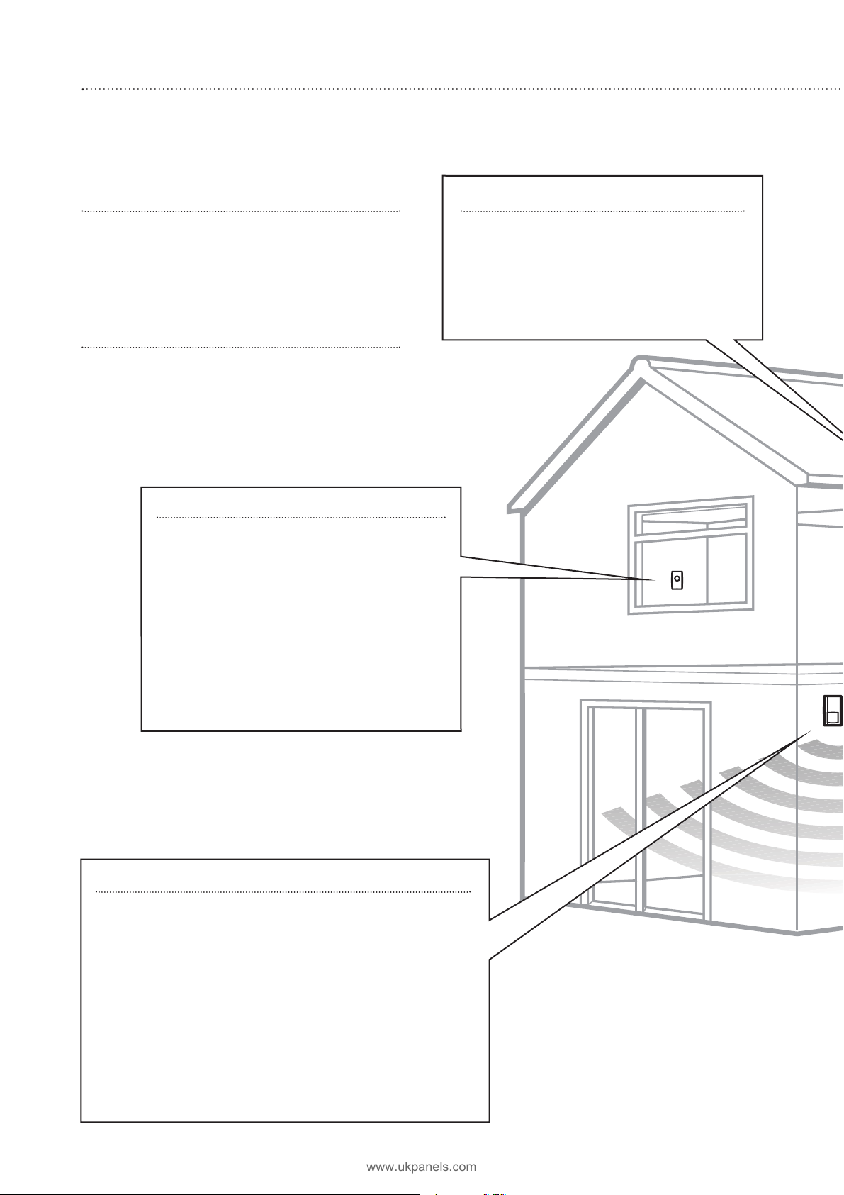
Location planning
Work out the best places to locate the devices for maximum protection. Having chosen the locations
Operating range
All devices must be within 30 metres of the
siren unit and must not be mounted on or near
large metal objects. Avoid obvious sources of
electrical interference such as fridges and
microwave ovens.
Tamper switches
When mounting devices ensure that any
tamper switches close fully. On uneven surfaces
it may be necessary to place packing behind the
switch for reliable operation.
4
1
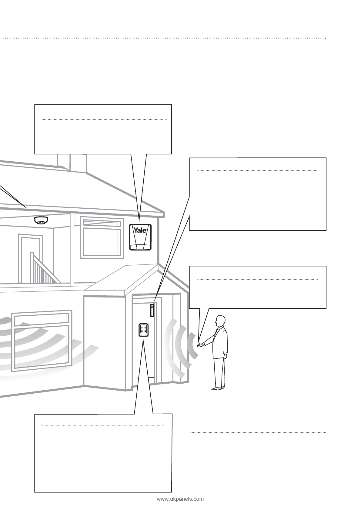
Smoke detector accessory
• Mount on the ceiling at the top of a
stair well, or where smoke would most
likely be detected.
• Install additional detectors if there are
closed doors preventing smoke from
reaching detectors.
Help button accessory
The help button provides extra protection
for you and your family. When help is needed
the button can activate your alarm
immediately - even when the system is
disarmed.
• Mount on bedroom wall or by the front
door
• Not clearly visible to an intruder
• Easily accessible
• Out of reach of children
• Not outdoors
PIR movement detectors
• Mount in a position such that an intruder would normally
move across a PIRs field of view.
• Height should be between 1.7 and 2.3 metres above
floor level.
•Location in a corner will ensure wider room coverage.
• Do not mount a PIR where its field of view will be
obstructed e.g. by curtains, ornaments etc.
• Do not point directly at sources of heat e.g. fires or
boilers, and do not position directly above radiators.
•Avoid mounting a PIR directly facing a window.
• Do not point a PIR at a door protected by a door/window
contact.
www.ukpanels.com
Page 5
5
Extend the system
Extend the system in the future to increase
your security or as your needs change.
For example, add extra PIR detectors in
bedrooms and extra door/window contacts.
Keyfob remote control accessory
Can be used outside the premises and
kept on your keyring.
Door/Window contacts
Use one door/window contact on a door
that is used as the main point of entry and
exit, usually your front door. The other
door/window contact can be used to protect
another entry point such as a rear door.
• Mount as high as possible.
• Do not aim a PIR at this door or window.
Siren
Choose a position on an external wall
where the siren would be most prominent.
Mount as high as possible, out of easy reach.
Keypad remote control
•The keypad should be sited next to the
main point of entry/exit so that the
system can be disarmed/armed within 20
seconds of entering/leaving the premises.
• Ensure that the keypad is not visible from
the outside of the premises.
• Mount at chest height for ease of use.
• Designed for indoor use only.
www.ukpanels.com
Page 6
PIR movement detectors
Remove the fixing screw and cover assembly
and insert the three AA batteries as shown.
•The light steadily flashes for 30 seconds while
components initialise.
6
+
+
+
Unpack all the parts on a table top
The easiest way to get to know the system and get it up and running quickly is to get
all the devices and accessories programmed on a table top before locating and mounting them.
2
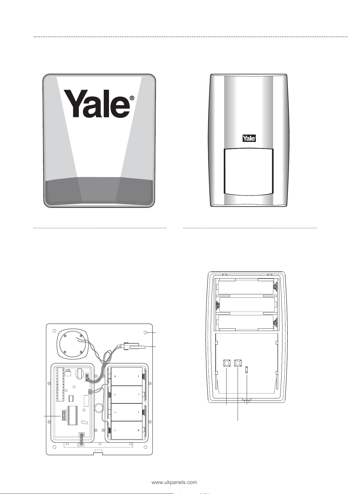
Siren
WARNING
The siren is very loud, be prepared! Take care
not to activate the siren tamper switch
unnecessarily.
1 Remove the cover by unscrewing the single
screw located at the bottom.
2 Remove the covers of the two internal
compartments.
3 Insert the four D batteries as shown.
There is a slight pause while the unit initialises.
The siren will then beep and the LEDs flash.
Tamper
switch
Jumper switch
Learn/Test button
Tamper
switch
Fixing holes
x 4
Jumper
switches
www.ukpanels.com
Page 7

Door/window contacts
1 Remove the cover of each door/window contact
by loosening the fixing screw.
2 Insert t wo AAA batteries into each detector as
shown. The indicator LED will flash briefly.
7
Keypad remote control
Remove the cover and insert the 3 AAA alkaline
batteries as shown. The ‘Tx’ LED will flash briefly
while components initialise.
Please note, the Home button on the operating
panel and the jumper switch inside (do not move)
have no function on this model.
Smoke detector accessory
Remove the cover and insert the four AAA
batteries as shown.
Keyfob remote control accessory
Slide off the battery cover, insert the
23A/MN21 battery as shown, and replace
battery cover. Switch to ‘on’.
Help button accessory
Remove the cover by loosening the fixing
screw and insert the 12V battery (supplied) as
shown. Please ensure you observe batter y
polarity.
Tamper
switch
Jumper
switch
Tamper
switch
Jumper
switch
Magnet
Extension terminals
Learn/Test button
Learn/Test
button
On/Off switch
www.ukpanels.com
Page 8

3
8
Program the siren and keypad
The siren is the heart of the system. First, teach the siren to recognise (learn) the keypad.
Jumper in
‘off’
‘parked’
position
Jumper in
‘on’
position
Use of jumper switches
The siren, PIR and door/window contact each
have internal switches, or ‘jumpers’, which control
various functions. The jumpers are either ‘on’ or
‘off’. ‘On’ is when the jumper connects two pins,
‘off’ when it is removed. To prevent the jumper
from being lost when removed, it can be ‘parked’
on one pin as shown:
Programming the siren and learning in the
keypad
WARNING
The siren is very
loud, be prepared!
Take care not to
activate the siren and
keypad tamper switches
unnecessarily. Leave the
keypad face downwards
after programming to
avoid accidental
operation of the tamper switch
The siren is programmed by the use of jumper
switches in the left hand compartment. Ensure all
jumpers are in the ‘on’ position before starting.
1 Lift off jumper number 1 and park it. The siren
will beep and flash. The siren is now in learn
mode.
2 Learn-in the keypad by entering 0000, then
press TEST. The ‘Tx’ LED will flash showing that
the keypad is in learn mode.
3 Press TEST again, then 1. The keypad will beep
and the siren confirm.
4 Press OFF twice on the keypad to exit
programming mode. Place the keypad face
down to avoid activating the tamper spring .
5 Replace jumper 1 in the siren to the ‘on’
position, the siren will confirm with a beep and
a flash as it exits learn mode.
• If accidentally left in the learn mode, the sytem
will revert to normal after about 3 minutes.
www.ukpanels.com
Page 9

Further siren programming
The siren can be configured to your personal
requirements by the use of jumpers.
Jumper positions
J7 on = jamming detection ‘off’;
off = jamming detection ‘on’
J6 on = normal, J6 off = clear memory
J5 on = stand alone operation;
off = slave operation, not used in this
system
J3 on, J4 on = 3 minute siren ‘on’ period
J3 off, J4 on = 5 minute siren ‘on’ period
J3 on, J4 off = 10 minute siren ‘on’ period
J3 off, J4 off = 1 second siren ‘on’ test
period
J2 on = LEDs ‘on’ during siren period;
off = LEDs remain ‘on’ (after an alarm)
until system is disarmed
J1 on = normal; off = learn-in mode
•Jumper 5 must be left in the ‘on’ position.
• J6 must be left ‘on’ in normal ser vice
otherwise the siren will lose its learn-in
memory when the batteries are replaced.
•With J7 ‘off’, jamming by radio interference is
detected when continuously present for more
than 30 seconds and activates the siren only
when armed.
• If jumper 3 and jumper 4 are removed during
the learning-in process, the siren will sound for
1 second if accidentally activated and is useful
for testing. Ensure they are replaced before
replacing the covers.
6 Replace the battery and electronics
compartment covers, ensuring the gasket
between the electronics compartment and
cover is correctly located and the wires placed
in their slots to ensure a good seal from the
environment.
9
Tamper alarm
If the siren detects a tamper condition it will
activate the siren for the programmed period. If
the tamper condition persists the siren will sound
a series of five pips either every time the system
is armed or when the tamper is enabled, to
indicate a fault.
Previous alarm warning
If there has been an alarm when you were
away the siren will sound and flash for 3 seconds
when being disarmed.
Warning If the siren is activated for 3 seconds
when you disarm your system there could be an
intruder still in your premises.
Strobe LED visibility
The strobe LEDs are intended to work together
with the siren to identify the alarm source.
The strobe is not designed to be viewed from
directly underneath or from the sides. It is
designed to be clearly visible from 10 to 50
metres in normal daylight conditions, away from
direct sunlight.
Radio jamming
This unit is equipped with the latest type of
radio receiver using AM radio technology. If the
system is armed, any criminal attempt to prevent
(or jam) the detector transmissions will be picked
up as interference and will trigger an alarm.
If the alarm is frequently triggered by
interference there may be high levels of unusual
radio signals in your area. Some kinds of
electronic equipment can generate this kind of
radio interference.
In the unlikely event of you experiencing
problems with interference, it is recommended
that you switch jamming detection off.
Please telephone our helpline if you require any
further assistance.
www.ukpanels.com
J7
J6
J5
J4
J3
J2
J1
Jamming detection
Clear memory (leave ‘on’)
Standalone mode (leave ‘on’)
Siren activation time
Siren activation time
Strobe activation mode
Learning-in mode (leave ‘on’)
Page 10

10
Mounting the siren and keypad
WARNING Before mounting the keypad and siren ensure that the system tamper is
disabled as described below.
4
Disabling the system tamper
Before mounting it is important to disable the
tamper to avoid the siren sounding an alarm.
1 Enter 0000 then press TEST. The ‘Tx’ LED will
flash showing the keypad is in program mode.
2 Press TEST again, then 2. The keypad will beep
and the siren confirm. The system tamper is
now disabled. Activating the siren or keypad
tamper switches will not cause an alarm.
3 Exit the programming mode by pressing OFF
twice.
•The system tamper will remain disabled for 1
hour to allow you to mount the siren and
keypad. If more time is required, simply repeat
the steps above.
Mounting the siren
WARNING The siren is
extremely loud!
The tamper switch
plunger protrudes
through the back of the
unit, so that if the siren
is pulled from the wall
the alarm is activated.
Ensure it is fully
depressed when the siren
is mounted. If there is a
gap, pack with a suitable
spacing material.
1 Having chosen your
location ensure that
the sytem tamper is
disabled, repeat the
steps to disable
tamper if necessary.
2 Using the large screws
provided, mount on
wall through the base
plate mounting holes
shown.
3 Fix the siren cover with the securing screw.
Mounting the keypad
1 Ensure system tamper is disabled. Repeat the
steps to disable the system tamper if
necessary.
2 Choose a suit able location, as described in
‘Location planning’ (usually next to main
entry/exit point).
3 On the rear plate of the keypad, break through
the four knockouts (where the plastic is
thinner).
4 Using the holes as a template, drill holes in the
surface and insert the wall plugs if fixing into
plaster or brick.
5 Attach the front of the keypad to the rear plate,
ensuring that the tamper switch closes. If the
tamper switch does not close it may be
necessary to pack out with a suitable spacing
material (keypad will beep ever y 30 seconds if
the tamper switch is not closed).
6 Re-insert and tighten screw.
Checking operation
Now that the siren and keypad are mounted
into position you can quickly check the operation
of the system by arming and disarming.
1 Enable the system tamper by entering 00 0 0,
then TEST. ‘Tx’ LED will flash.
2 Press TEST again, then 3. System tamper will
now be active.
3 Press OFF twice.
4 Press 00 0 0, then ARM. Siren should beep once
and flash LEDs. If siren beeps five times, the
siren tamper switch is not closed, to rectify the
problem, disable system tamper and ensure
that the switch closes.
5 Press 00 0 0, then OFF. Siren should beep twice
and flash LEDs.
Tamper switch plunger
must be pressed in fully by
wall surface
Fixing holes x 4
www.ukpanels.com
Page 11

Learning in PIRs and Door/Window
contacts
To learn PIRs and door/windows contacts into
the system follow the steps below.
1 Enter 0 0 00, then press TEST. the ‘Tx’ LED will
flash showing the keypad is in program mode.
2 Disable t amper by pressing TEST then 2. The
keypad will beep and the siren confirm.
3 Enter learn mode by pressing TEST then 4. The
keypad will beep and the siren confirm. The
PIRs and Door/window contracts can now be
learnt into the system.
4 Activate the learn/test button on each detector
in turn. The siren will beep as each detector is
learnt in.
5 Exit learn mode by pressing TEST then 5, the
keypad will beep and the siren confirm.
6 Exit programming mode by pressing OFF twice.
Mounting methods
Yale provide two methods of mounting. Choose
either the self adhesive pads or the screws and
wall plugs supplied.
Self adhesive installation for door/window
contact
Clean the surface with a suitable degreaser.
Remove the protective covering from one side of
the double sided adhesive pad and firmly apply to
the back of the device. Next remove the other
cover and firmly press the item onto the desired
location.
• Do not use the adhesive pad method of
installation on a surface with peeling or cracked
paint, or on a rough surface.
Screw mounting
Remove the front of the device, and, if
necessary, break through the appropriate knockout
(where the plastic is thinner).
Using the holes as a template, drill holes in the
surface and insert the wall plugs if fixing into
plaster or brick.
Testing the radio performance
Before permanently installing detectors, check
that the siren will receive the system radio
transmissions by doing a simple radio range test.
1 Ensure that the system tamper is disabled.
2 Hold the detector in the desired location and
press the learnt/test button, siren should
respond with a single beep.
3 When you are satisfied that the detectors work
in your chosen locations, proceed with the
installation as described below.
• If the siren does not respond, the location may
be out of range, try alternative locations until
reliable radio contact is obtained.
Door/Window contacts
1 Ensure the system
tamper is disabled,
repeat steps to extend
the tamper disable
time a further hour if
necessary.
2 Ensure the jumper
switch is in the test
‘on’ position.
• In this position the
indicator light will
illuminate every time
the door contact is
operated.
3 Fit as described in
‘Mounting methods’,
mounting the detector
base on the frame and
aligning the magnet by the arrow as shown.
•The magnet should not be more than 8mm
from the detector when the door is closed.
• Ensure the tamper switch spring is positioned
so that it makes contact with the mounting
surface through the tamper switch aperture.
• If the door contact cannot be mounted on the
doorframe, use the HSA3090 multiple
door/window contact accessory kit with a
length of wire to mount the door contact
remotely (see below).
• When fitting to a window, fix the magnet to the
moving part and the detector to the frame.
4 Fix the detector on its base and secure with
screw. Test it by opening and closing the door
or window. The light will flash when an open
condition is detected.
5 Remove the detector, put the jumper switch in
the normal ‘off’ position. Screw the detector
back onto its base.
11
Jumper
switch
Door/
Window
Frame
Align
8mm (max)
Programming and mounting detectors
Before mounting detectors ensure that the system tamper is disabled as described
in section 4, point 1 (page 10).
5
Learn/
Test
button
PIR
Learn/
Test
button
Door contact
www.ukpanels.com
Page 12

• When the jumper is in the normal ‘off’ position
the indicator light will normally be off. It will
only light if there is a problem, either a low
battery or a tamper condition.
• Ensure the jumper is in the normal ‘off’ position
when testing is finished, otherwise low battery
and tamper conditions will not be shown.
Adding multiple door/window contacts
If difficulty is experienced fitting a door/window
contact because of space etc, the HSA3090
multiple door/window contact set should be used
(not included).
The magnet/contact pairs are wired using bell
wire (not supplied) to the extension terminal block
as shown. The knockout in the top of the
door/window contact must be removed to allow
the wire to pass through. The total length of wire
used must not exceed 10 metres. The
magnet/contact pairs should be no further than
8mm apart.
It is possible to use a single pair of multiple
door/window contacts with a detector if you
experience problems fitting the main unit to the
door frame.
When using multiple switches on a
door/window contact you can still use the detector
without having a magnet alongside the main unit.
PIR movement detectors
The PIRs have a built-in sleep timer to save
battery power. If there is no movement in front of
the PIRs for 1 minute, the PIRs will become
‘ready to signal’ and movement will now be
reported. The PIRs will sleep for 1 minute after.
Any movement detected in sleep time will not be
reported and will extend the sleep period by a
further 1 minute.
Ensure the test/normal mode
jumper switch is in the test ‘on’
position. This reduces the sleep
time to a few seconds and
enables the LED to flash every
time movement is detected.
1 Ensure the system tamper is
disabled, repeat steps to
extend the tamper disable time
a further hour if necessary.
2 Screw the rear case to the wall
using the appropriate
knockouts, as described in
‘Mounting methods’. The case has angled back
edges for neat corner mounting. If mounting in
a corner take care not to bend the rear case.
Screw the PIR front on.
3 Walk around the protected area noting when
the LED flashes and check that the detection
coverage is adequate.
•Remember to wait a few seconds after the PIR
has detected movement.
• Do not try to test the detection pattern by
walking straight up to, or away from the
detector.
4 When you are satisfied with the detection
coverage, remove the PIR, place the jumper in
the normal ‘off’ parked position and screw the
PIR back on to its case.
•With the jumper in the normal position the LED
will not normally light unless there is a problem,
either a low batter y or a t amper condition. In
the event of a low battery, replace the
exhausted batteries with fresh alkaline
replacements.
• Do not position a PIR to look directly at a door
protected by a door contact, this could cause
the door contact and PIR radio signals to be
transmitted at the same instant when entering,
cancelling each other out.
• Ensure the jumper is in the normal ‘off’ position
when testing is finished, otherwise low battery
and tamper conditions will not be shown.
Enabling system tamper
After mounting your detectors enable the
system tamper as follows.
1 Enter 0 0 00 then press TEST. The ‘Tx’ LED will
flash showing the keypad is in program mode.
2 Press TEST again, then 3. Keypad and siren will
beep in confirmation.
3 Exit programming mode by pressing OFF twice.
Installation is now complete.
12
Corner fixing
holes x 4
Surface fixing
holes x 2
Knockout
removed for
wire
Door/window
switches wired
in series
Magnets
www.ukpanels.com
Page 13

13
Setting or changing your user PIN
code
1 Put the keypad into program mode by entering
the 0000 default code and pressing TEST.
2 Enter 0 0 00 then CLR, enter your new 4 digit
PIN code and press PROG, the keypad will
beep to confirm.
3 Press OFF twice on the keypad to exit the
program mode.
• If the PIN doesn’t change, repeat the above
sequence quickly without gaps.
•Write your code in the space provided below so
you don’t forget it.
• If you wish to change the PIN code again, you
will have to enter your existing code, rather
than 0000.
• If an unauthorised user attempts to guess the
code by entering random four digit numbers,
the keypad will produce a series of warning
beeps. On a fourth wrong attempt, it will lock
out for one minute.
Arming the system
To arm the system, enter your 4-digit PIN code
and press ARM, the siren will beep once and
flash. You can now leave the premises.
•After arming the system you have 20 seconds
exit time to leave the premises. Any detector
activated during this time will be ignored by the
system.
•The system does not have an audible
countdown during the exit time.
•System tampers will be active during the exit
time.
Disarming the system
After entering the premises, disarm the system
by entering your PIN code and press OFF. The
siren will beep twice and flash.
• Upon entering the premises, the first detecter
activated (usually a door/window contact on the
main point of entry) will cause the 20 second
entry time to start. During the entry time any
detector activated will be ignored by the
system.
•The siren will beep once when the first detector
is activated.
•If the system is not disarmed before the entry
time expires the alarm will be activated.
•The system does not have an audible
countdown during the entry time.
•System tampers will be active during the entry
time.
Stopping the alarm
If the alarm is activated the siren wil sound and
flash the strobe LEDs. To stop an alarm, enter your
PIN code and press OFF. The siren will stop
sounding and beep twice.
PIR sleep timer
Please remember when testing, that the PIR
has a sleep timer. See section 4 for details.
Using the system
Arm and disarm the system and practice using it. Trigger the alarm by arming the system
and opening protected doors/windows and walking past PIRs. Now’s the time to set
your pin code and show the rest of the family how simple it is to use.
6
My PIN code
www.ukpanels.com
Page 14

14
Adding accessories
To provide additional protection you can add extra door/window contacts, PIRs, keyfob
remote controls, keypad remote controls, help buttons and smoke detectors. These are
available separately from your local stockist.
Putting the system in and out of learn
mode
Put the system into learn mode and disable the
system tamper using the keypad as follows.
1 Enter your PIN code, then press TEST. The ‘Tx’
LED will flash showing the keypad is in program
mode.
2 Disable t amper by pressing TEST then 2. The
keypad will beep and the siren confirm.
3 Enter learn mode by pressing TEST then 4. The
keypad will beep and the siren confirm. The
PIRs and Door/window contacts can now be
learnt into the system.
4 Learn in the appropriate device as described.
5 Exit learn mode by pressing TEST then 5, the
keypad will beep and the siren confirm.
6 Enable system tamper by pressing TEST then 3.
The keypad will beep and the siren confiirm.
7 Exit programming by pressing OFF twice.
• When learning in accessories that are not
tamper protected (such as the helpwatch) it is
not necessary to disable the system tamper,
therefore steps 2 & 6 can be ignored.
• If accidentally left in learn mode, the system
will revert to normal in about 3 minutes.
• If accidentally left with tamper dissabled the
system will revert to normal in about 1 hour.
Remote keyfob accessory
The keyfob accessor y allows you to operate the
system from outside the premises. Along with
panic attack feature, the keyfob also allows you to
put the system in and out of learn mode and
disable/enable the system tamper.
• Please note that the Home feature is not used
with the HSA3400 system.
Programming
Learn in the keyfob as follows:
1 Enter learn mode as described.
2 Press the Arm button (ensure keyfob is
switched on). The keyfob LED will light and the
siren will beep to confirm.
3 Exit learn mode as described.
Arming and disarming
The system is armed by pressing the ARM
button for at least 1 second (this delay feature
prevents accidental opperation). The system is
disarmed by pressing the DISARM button in the
same manner. The switch at the side prevents the
keyfob from transmitting accidentally.
WARNING Please note that when arming the
system with the keyfob, the entr y/exit feature will
not be active. When the Arm button is pressed,
the system will arm instantly. Any activation of a
detector will cause an instant alarm.
Panic feature
You can cause the alarm to sound, regardless of
whether the system is armed or disarmed, by
pressing and holding down the Panic button. The
Panic button has to be pressed for more than 5
seconds to operate. This is a safety feature to stop
accidental operation.
Tamper disable/enable
The system tamper can be accessed with the
keyfob as follows:
1 To disable the system tamper, press the Arm
and Home buttons simultaneously until the
siren confirms (approx 5 seconds).
2 To enable the system tamper, press the Arm
and Panic buttons simultaniously until the siren
confirms (approx 5 seconds).
System learn mode
The system learn mode can be accessed with
the keyfob as follows:
1 To enter learn mode, press the Panic and Home
buttons simultaneously until the siren confirms
(approx 5 seconds).
2 To exit learn mode press Disarm, the siren will
confirm.
www.ukpanels.com
Page 15

15
Adding the help button
Program your help button before installation and
test in the desired location before mounting.
Programming
1 Follow sections 1 and 3 (Inserting batteries and
Location planning).
2 With the system in learn mode, press and hold
the red button on the help button – the LED will
light momentarily and your system will confirm
the transmission.
3 Take your system out of learn mode.
•The help button can be tested by entering learn
mode (see user guide) and activating the help
button. The siren will beep in response to the
activation. Please ensure you exit learn mode
after testing.
Using
To activate, press and hold the red button for at
least 2 seconds – LED will light momentarily and
the alarm will be activated.
To silence an alarm, press and hold down the
red button, after 10 seconds the LED will light
momentarily for a second time – alarm will be
silenced
• Please note that silencing the alarm with the
help button does not reset the system. If the
alarm is armed prior to activation, the system
will re-arm after being silenced with the help
button.
Adding the smoke detector
1 Follow sections 1 and 3 (Inserting batteries and
Location planning).
2 With the system in learn mode, press the
learn/test button on the smoke detector until
siren confirms.
3 Exit learn mode.
•The smoke detector will indicate a fire by
sounding the built-in siren, lighting the LED, and
sounding the external siren.
•The smoke detector will produce a warning
beep and the LED will flash every 30 seconds if
the batteries are near exhaustion.
•The learn/test button can be used to test the
smoke detector. The detector will sound a twotone confirmation and the siren will beep.
Please ensure that you test smoke detectors
regularly.
Adding further PIRs and door/window
contacts
1 Disable t amper and enter learn mode.
2 Press the learn button in the device. The siren
will confirm.
3 Exit learn mode and after mounting the
detector, enable tamper protection.
Adding extra keypads
Additional keypads can be added to the system,
for instance alongside another point of entr y/exit.
• Please note that the Home feature (extra button
on accessory keypads) is not used on the
HSA3400 system.
1 Using your original keypad, disable the system
tamper and enter the learn mode.
2 Enter 0 0 00 on your new keypad, then press
TEST. The ‘Tx’ LED will flash showing that it is
in program mode.
3 Press TEST again, then 1. Keypad will beep and
the siren confirm.
4 Press OFF twice on the new keypad.
5 Using either keypad, enable system tamper
(after mounting new keypad) and exit the learn
mode.
Adding extra keyfob remote controls
1 Using your original keyfob, enter the learn
mode.
2 Press the Arm button on your new keyfob, the
siren will confirm.
3 Exit learn mode using either keyfob.
•Now both keyfobs can be used to operate the
alarm and learn further devices (including extra
keyfobs) into the system.
www.ukpanels.com
Page 16

16
Changing the batteries
Always use alkaline batteries as replacements, any other type of battery (such as heavy
duty) can cause problems with the operation of the system. Typical life of siren batteries
is two years, whilst detectors will operate for three years before batteries need changing.
Always ensure you disable the system tamper when changing batteries.
Disabling and enabling system tamper
The keypad or the keyfob remote control
accessory can be used to disable and enable the
system tamper feature. This allows batteries to be
changed in any tamper protected device without
causing an alarm.
Using the keypad remote control
Disabling tamper
1 Enter your PIN code and press TEST. The Tx
LED will flash showing the keypad is in
program mode.
2 Press TEST again, then 2. The keypad will beep
and the siren confirm.
3 Exit the programming mode by pressing OFF
twice.
Enabling tamper
1 Enter your PIN code and press TEST.
2 Press TEST, then 3. The keypad will beep and
the siren confirm.
3 Exit the programming mode by pressing OFF
twice.
Using the keyfob remote control accesory
Disabling tamper
Press the Arm and Home buttons
simultaneously until the siren confirms
(approximately 5 seconds). The keyfob LED will
also flash.
Enabling tamper
Press the Arm and Panic buttons
simultaneously until the siren confirms
(approximately 5 seconds). If left in the tamper
disable mode, the system will revert to normal
after 1 hour.
Siren
The siren will produce a series of pips when
armed and disarmed, and an interrupted alarm
sound (if activated) if the siren batteries are near
exhaustion. Change the batteries as soon as
possible. The sound will be reset when the
batteries are changed.
•You can determine if your siren is sounding a
tamper warning or a low battery warning by
arming and disarming the system. If the siren
produces 5 pips when the system is armed and
disarmed, the batteries are low. If the siren
produces 5 pips, only when the system is
armed, the tamper switch has been disturbed.
1 Disable the system tamper.
• When changing batteries allow 1 minute
between taking out the old batteries and
replacing with new.
WARNING After the batteries have been
changed the system tamper will become active
again. To avoid the siren sounding in alarm, ensure
that you follow the next step before attempting to
refit the siren cover.
2 With the new batteries fitted disable the
system tamper again.
3 Refit the siren cover.
4 Enable the system tamper.
PIR and door/window contact
The LED will flash everytime the device is
activated indicating a low battery.
1 Disable system tamper.
2 Remove device from mounting.
•Before changing the batteries check that the
tamper switch closes when mounted.
3 Change the batteries with alkaline
replacements.
4 Screw device back on.
5 Enable system tamper.
Keypad remote control
To indicate a low battery, the ‘Active’ LED will
flash repeatedly every time the device is used.
1 Disable system tamper.
2 Remove keypad from mounting.
•Before changing the battery check that the
tamper switch closes when mounted.
3 Change the battery with alkaline replacement.
4 Screw keypad back on.
5 Enable system tamper.
Keyfob remote control accessory
The LED will either be very dim or will not light
at all when the battery is low. Change the battery
as soon as possible with an alkaline replacement.
Smoke detector
The LED will flash and the sounder will beep
every 30 seconds to signal low battery. Change
the batteries as soon as possible with alkaline
replacements.
Help button
Remove the cover by loosening the fixing
screw and insert a new 12V battery.
www.ukpanels.com
Page 17

17
Model: HSA3400
HSA3020
HSA3060
HSA3010
HSA3050
HSA3045
HSA3080
HSA3030
HSA3070
www.ukpanels.com
Page 18

18
Specifications
All devices
EMC
Tested to ETS 300 683
Radio Components tested to EN
300 220-1
Environmental conditions
-10°C to 40°C, relative humidity
70% non-condensing for all units
except the external siren. Siren: -20°C
to 50°C, relative humidity 95% noncondensing
Radio operational range
30m in a typical domestic
installation, range can vary depending
on building construction, device
positions and RF environment
Housings ABS/polycarbonate
Siren
Siren output 104dBA sound pressure @
1m minimum
Radio 433.92MHz AM super heterodyne
receiver with jamming detection
Power supply 6V, 4 x D alkaline cells. 3
years typical service life
Passive infra red (PIR) detector
Alarm processing Microprocessor
controlled dual edge sequential pulse
count with pulse length discrimination
Radio 433.92MHz AM transmitter
Power supply 4.5V, 3 x AA alkaline cells.
3 years typical domestic service life, 1minute sleep timer
Movement detection range 15m , 110°
Door/window contact
Radio Microprocessor controlled
433.92MHz AM transmitter
Power supply 3V, 2 x AAA alkaline cells. 3
years typical domestic service life
Smoke detector
Radio Microprocessor controlled
433.92MHz AM transmitter
Power supply 6V, 4 x AAA alkaline cells. 3
years typical domestic service life
Keyfob remote control
Radio Microprocessor controlled
433.92MHz AM transmitter
Power supply 12V, 23A/MN21 alkaline
miniature "lighter" battery. 3 years
typical domestic service life
Keypad remote control
Radio Microprocessor controlled
433.92MHz AM transmitter
Power supply 3 x AAA alkaline cells. 3
years typical domestic service life
Help button
EMCTested to EN 300 220-1 and ETS
300 683
Environmental conditions -10°C to
40°C, relative humidity 70% noncondensing
Radio operational range 30m in a
typical domestic installation. Can vary
depending on building construction and
RF environment
Radio Microprocessor controlled
433.92MHz AM transmitter
Power supply 12V 23A/MN21 alkaline
miniature ‘lighter battery’. 3 years
typical domestic service life
0560
www.ukpanels.com
Page 19

19
Trouble shooting
Siren
Siren does not respond to keypad
• Keypad low batter y or bad connection. Check
battery connections and polarity, if OK replace
battery with alkaline equivalent.
•Siren batteries are completely exhausted.
Check siren batteries by removing siren cover, if
there is no tamper alarm when removed,
replace batteries with new alkaline equivalents.
• Keypad not learnt-in. If siren produces a tamper
alarm when the cover is removed, and keypad
is OK, learn-in the keypad.
Siren produces a 3 second alarm when disarmed
•There has been a previous alarm and there
might be an intruder still in the premises.
Siren produces a series of pips when armed or
disarmed
•The siren has low batteries. Check that the
siren produces a series of pips when arming
and disarming, indicating low batteries. Change
batteries with new alkaline replacements.
•The siren tamper switch has been disturbed.
Check that the siren produces a series of pips
only when arming, indicating a tamper
condition. Check that the siren cover is firmly
secured and the tamper switch plunger is in
contact with the wall. If not use suitable
packing material to fill gap.
Siren produces an interrupted tone when
sounding an alarm
•The siren has low batteries. Change batteries
with new alkaline replacements.
Keypad
Keypad produces a beep every 30 seconds
•The tamper switch at the rear of the keypad is
open. Ensure the switch closes when the
keypad is mounted.
PIR
PIR does not respond to movement
•Previous movement has triggered the PIR sleep
timer is preventing subsequent movement
detection. Arm system and vacate protected
room for at least 1.5 minutes before testing.
PIR is slow to respond
•This is normal, the PIR has sophisticated false
alarm filtering that will filter out random
fluctuations and responds to genuine
movement across field of view, it is less
sensitive walking directly towards it.
PIR gives false alarms
• Check pets have no access to protected area.
• Check that PIR is not pointed at sources of heat
or moving objects, e.g. fluttering curtains.
• Check that PIR is not mounted above convector
heaters or pointing directly at windows.
PIR LED flashes when jumper is in normal position
•Batteries are low or the tamper switch is
disturbed. Check that the tamper switch spring
is making contact with base. If the tamper
switch is OK, change batteries with new
alkaline replacements.
PIR does not respond to movement when jumper
is in test position
•Batteries are completely exhausted. Change
batteries with new alkaline replacements, LED
will flash for 30 seconds while components
initialise.
Door contact
Door contact LED flashes when jumper is in
normal position
•Batteries are low or the tamper switch is
disturbed. Check that the tamper switch spring
is making contact with the mounting surface. If
the tamper switch is OK, change batteries with
new alkaline replacements.
Door contact does not respond to door opening
when jumper is in test position
•Batteries are completely exhausted. Change
batteries with new alkaline replacements
•The magnet is too far away from the door
contact. Check that the gap between door
www.ukpanels.com
Page 20

Key points
Stopping the alarm
• Enter your PIN code and press OFF on the
keypad
• Press Disarm on the keyfob accessor y (if
purchased)
If any of the devices beep or flash, they ha ve
either
been tampered with
See trouble-shooting, page 19
or require a new battery
See how to change a battery, page 16
www.yale.co.uk
E-mail: info@yaleuk.com
Security Products UK Ltd.
Wood Street, Willenhall, West Midlands,
WV13 1LA
Yale is a registered trademark
E2 11/03
www.ukpanels.com
 Loading...