

Page 1

An ASSA ABLOY Group brand
Kit 5
Home-monitoring
and intruder alarm system
HSA3095
Installation ¥ Programming ¥ Operating
Keep in a handy place for reference and for future maintenance
Helpline 01902 635998
Page 2

2
Introduction
General system overview
Thank you for choosing the Yale HSA3095
Home-monitoring and Intruder Alarm System. This
simple to install system has been designed with the
user in mind.
Two window stickers are included in the pack.
Please stick them in a front and rear window.
No connections
All the components are self contained and no
connections are needed between the units. There is
no need to damage the home decor, lift carpets or
run cables.
Number of devices
You can install up to 20 devices in the system. As
well as extra door/window contacts, PIRs and
smoke detectors, you can add keyfob remote
controls and keypads for added control
convenience.
Long battery life
There is no need to wire into the mains supply or
seek the services of a qualified electrician. The
control unit is powered by a plug top supply and all
other components are powered by battery (all
batteries included).
Batteries will operate for up to 3 years befor
e
they need changing. Regular testing and battery
changes (when notified by the system) will ensure
reliability and peace of mind. Please note that
alkaline batteries must be used as replacements.
Tamper proof system
The security detectors, control panel and external
siren are ’tamper’ protected. Any unauthorised
tampering with these items will result in an alarm.
This feature can be turned off by the user when a
battery change is required.
Unique monitoring
Home Manager is a r
evolutionary web-based
monitoring service that turns the average house into
an intelligent home, and helps you protect your
home and family against:
¥ Fire
¥ Flood
¥
Burglary
¥ Power failure
¥ Physical threat
¥ Doorstep aggression
¥ Falls by the elderly or infirm
Information and illustrations are subject to change within this document. Yale reserves the right to alter the specification and product
design at anytime without notice.
Yale¤ is a register
ed trademark. ' 2003 Security Products UK Ltd. All rights reserved.
T
he Home Manager monitors your home,
automatically raising the alarm by text message,
voice call and e-mail to up to 6 people of your
choice if something unexpected occurs, as well as
the internal and external alarm sirens activating.
In addition, the monitoring service allows you to
have complete control of your alarm system over
the internet, with event logs, arm/disarm facility
and safe at home functions. These are innovative
features that offer flexibility and control that you
would expect in this day and age.
Take care of your safety
Display extreme caution when using ladders or
steps, please follow manufacturers instructions.
Be careful when using hand and power tools and
follow the manufacturers guidelines when using
them. Take care that the correct tools are used.
Wear goggles or protective clothing where required.
The external Siren is extremely loud, please
ensure you replace the cover and retreat to a safe
distance before testing.
Warranty
Please complete and return the warranty card.
Yale offer extended periods of warranty, please see
warranty card for details.
Calling for help
Yale have a helpline team who are there to offer
advice or solve problems over the phone.
Helpline 01902 635998
Helpline service available 9am-5pm Monday to
Friday.
Caution
The dialling facilities must only be used with
persons who have consented to being contacted by
the system.
The system is not to be used to make 999
emergency calls directly. Yale do not hold
responsibility for any actions taken by emergency
ser
vices for incorrect use of the dialling facility.
Page 3

3
Contents
Contents
1 Location planning 4
2 Unpack the parts 6
3 Easy install programming 8
4 Installation/mounting 13
5 Testing the system 15
6 Monitoring service 16
7 Using the system 17
8 Configuring your system 20
9 Installing and using accessories 23
Changing the batteries 24
Trouble shooting 25
Specifications 26
Key points Back cover
HSA3010 Door/window contact
HSA3020 Passive infra-red (PIR) detector
HSA3030 3 x Passive infra-red (PIR) detectors
HSA3045 Help button
HSA3050 Exter
nal sir
en
HSA3060 Remote control (keyfob)
HSA3070 Smoke detector
HSA3080 Remote keypad
HSA3090 Multiple door/window contact switches
Accessories available
Recommended installation sequence
We recommend you follow the simple install
sequence, headings numbered 1-5.
Subsequent sections provide:
¥ Use of additional accessory devices including
keypad and keyfob remote controls
¥ Telephone connection
¥ Advanced protection and features
Carton contents
¥ Control panel & mounting bracket
¥ External siren,
¥ 2 x Passive infrared detector
¥ 2 x Door contact
¥ 1 x Flood detector
¥ 1 x Smoke detector
¥ 3-metre telephone cable
¥ Double socket line adapter
¥ 500mA 9V power adapter
¥ 2 x Door contact magnets
¥ 2 x Large adhesive pads
¥ 2 x Small adhesive pads
¥ 6 x 1.5VAA alkaline batteries
¥ 8 x 1.5V AAA alkaline batteries
¥ 1 x 12V MN21 alkaline battery
¥ 4 x 1.5V D alkaline batteries
¥
6 x fixing scr
ews
1
/2x No 6 Phillips r
ound head
¥ 4 x fixing screws 1 x No 8 Phillips round head
¥ 8 x small wall plugs
¥ 4 x fixing screws 2 x No 8 Phillips round head
¥
4 x fixing screws 2 x No 10 Phillips round head
¥ 10 x medium wall plugs
¥ Instruction booklet
¥ Home monitoring user guide
¥ 6 x contact cards
¥ 2 x window stickers
¥ Intamac user guide
Page 4
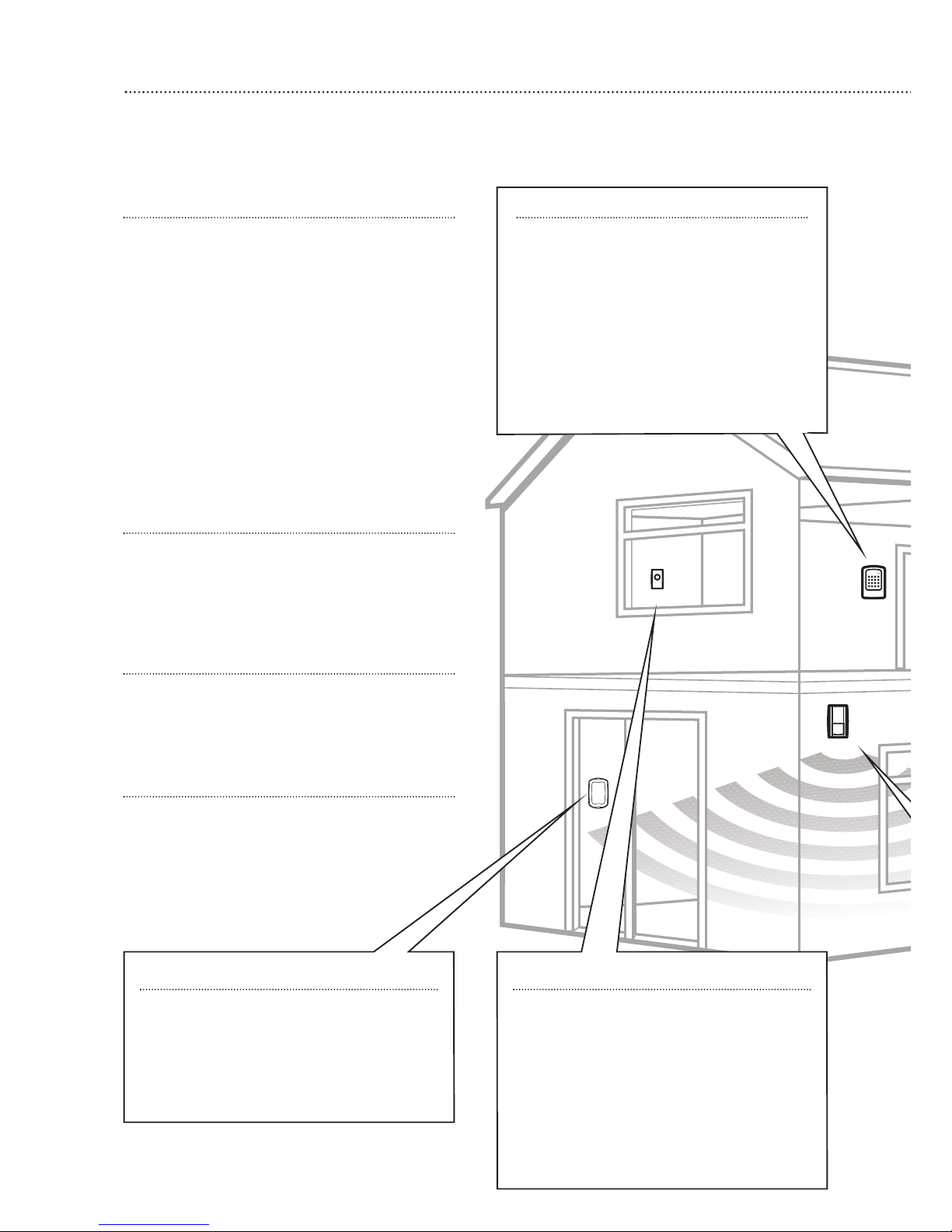
Location planning
Work out the best places to locate the devices for maximum protection. Having chosen
the locations
do not mount at this stage.
4
1
Keypad remote control accessory
When used as second keypad, it is ideal in
bedrooms or at the top of a stairwell so the
ground floor can be armed when going to
bed for the night. Or, at a side or back door
for alternative entry.
¥ Mount at chest height for ease of use
¥ Designed for indoor use only
¥ Keypad should be accessible from a
protected entry/exit point
¥ Ensure that the keypad is not visible from
the outside of the premises.
Home and away mode planning
The home arming mode allows the premises to
be part armed so that no one can get inside without
warning the occupier, yet the person already inside
the house can move freely without triggering the
alarm. For example the downstairs of a house can
be armed while upstairs can be disarmed allowing
the user to go to bed without causing an alarm.
If this feature is to be used, then it should be
planned now, before installation.
Decide what areas can be occupied when in
home arming mode, the sensors for these areas
should be programmed to home omit; and the
sensors activated on the path to access the control
unit should be to be set to home delay as explained
in Further programming (page 22).
Operating range
All devices must be within 30 metres of the
control unit and must not be mounted on or near
large metal objects. Avoid obvious sources of
electrical interference such as fridges and
microwave ovens.
Tamper switches
When mounting devices ensur
e that any tamper
switches close fully. On uneven surfaces it may be
necessary to place packing behind the switch for
reliable operation.
Extend the system
Extend the system in the future to increase your
security or as your needs change.
For example, add extra PIR detectors and
extra door/window contacts.
Help button accessory
The help button provides extra protection
for you and your family. When help is needed
the button can activate your alar
m immediately
- even when the system is disarmed.
¥ Mount on bedroom wall or by the front door
¥ Not clearly visible to an intruder
¥ Easily accessible
¥
Out of r
each of childr
en
Flood detector
¥ Mount flood detector higher than the
detection probes so that it does not get wet
when detecting a flood
¥ Use clip to position probes where water is
likely to be detected, for example the side of
a washing machine or dishwasher
Page 5
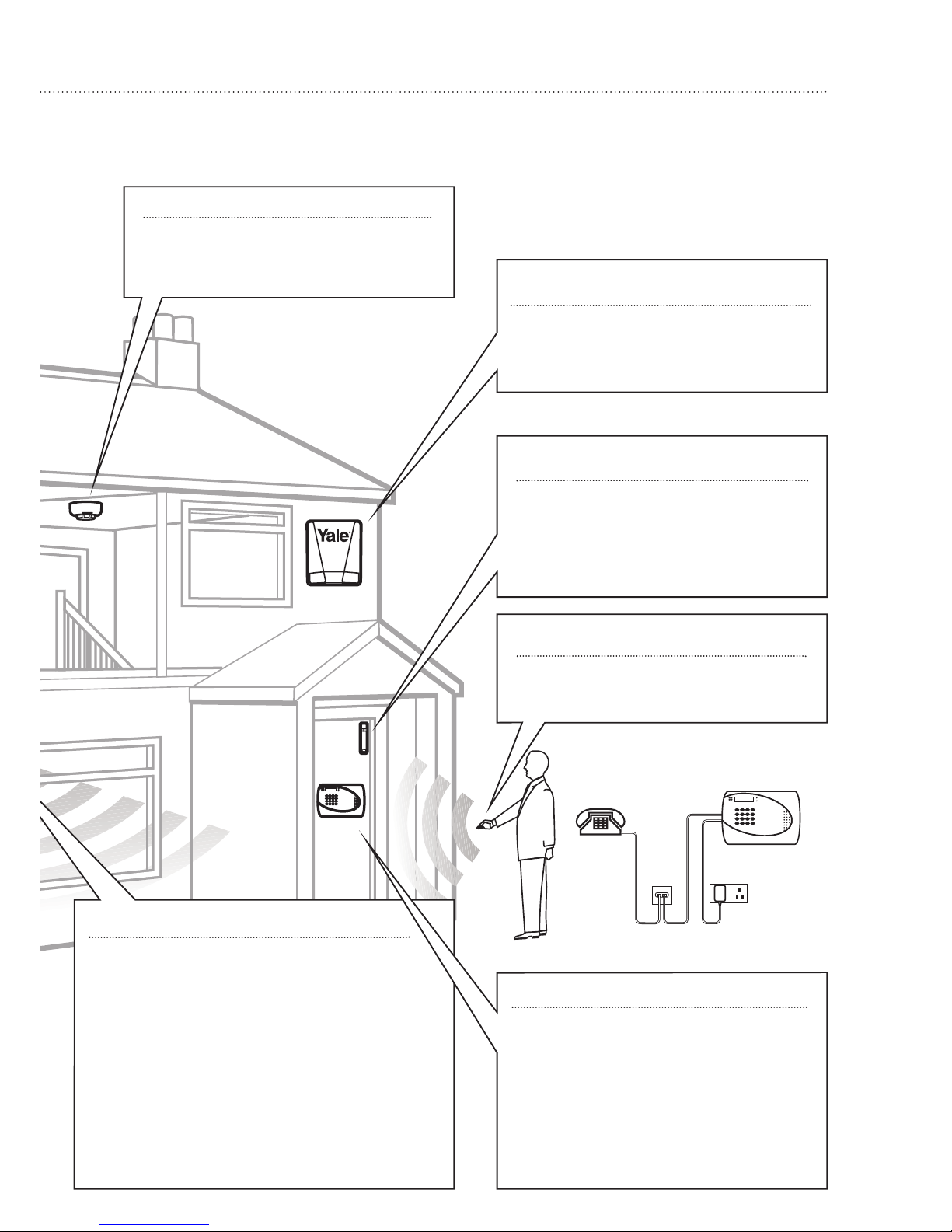
5
Smoke detector
¥ Mount on the ceiling at the top of a
stairwell, or where smoke would most
likely be detected.
PIR movement detector
¥ Mount in a position such that an intruder would
normally move across the PIRs field of view.
¥
Height should be between 1.7 and 2.3 metres
above floor level.
¥ Location in a corner will ensure wider room coverage.
¥
Do not mount the PIR where its field of view will
be obstructed e.g. by curtains, ornaments etc.
¥ Do not point directly at sources of heat e.g. fires or
boilers, and do not position directly above radiators.
¥ Avoid mounting the PIR directly facing a window.
¥ Do not point the PIR at a door pr
otected by a
door/window contact.
Keyfob remote control accessory
Can be used inside or outside the property
and can be kept on your keyring.
Door/Window contact
Select a door that will be the main point of
entry and exit, usually your front door.
¥ Mount as high as possible
¥ Do not aim a PIR at this door or window
Siren
Choose a position on an external wall where
the siren would be most prominent. Mount as
high as possible, out of easy reach.
Control unit
¥ Ensure the control unit is accessible when
entering thr
ough a protected entry/exit
point.
¥ Avoid mounting the control unit where it
would be visible from the outside of the
premises
¥
Locate by a mains socket and telephone
point.
Page 6
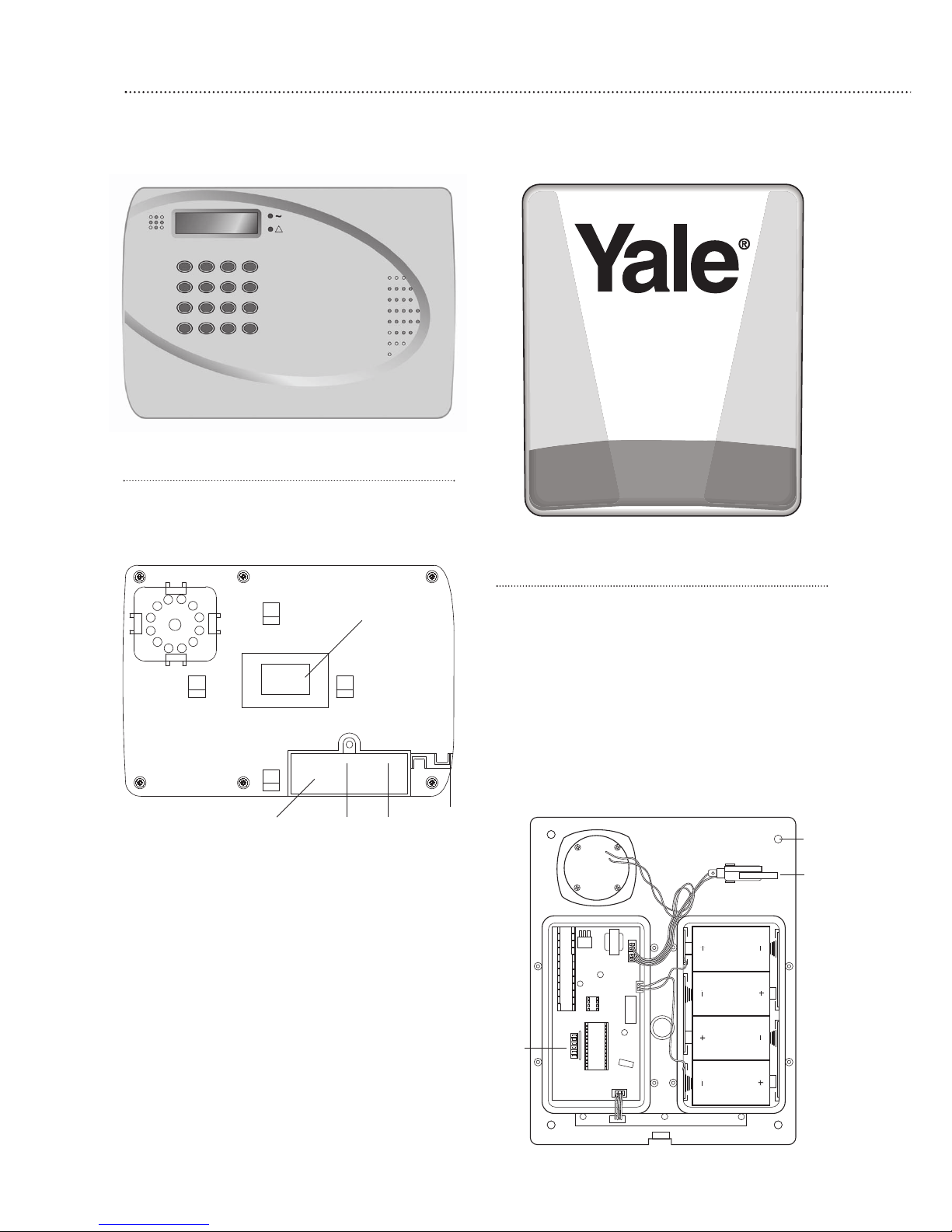
Control unit
Plug the power adaptor into the mains supply
wall socket and the other end into the control unit.
A long beep will be heard
¥
In addition to the adapter, there is a rechargeable
battery inside the control unit that serves as a
back up in case of a power failure. When the
battery is fully charged, it can provide back-up
power for a period of at least 8 hours. It takes
approximately 48 hours to fully charge the
battery. The control unit is equipped with a backlit
LCD display and keypad for easy operation in
dark. When mains power is missing, to conserve
the rechargeable battery, the backlit feature will
be disabled until mains power is again supplied.
¥
Do not connect the telephone line until section 6.
¥
Please make a note of the 16 character serial
number, located on the back of the control unit
and enter into the Intamac Home ManagerTMguide.
6
Unpack all the parts
The easiest way to get to know the system and get it up and running quickly is to get
all the devices and accessories programmed on a table top before locating and mounting them.
2
Siren
WARNING: The siren is very loud, be
prepared!
Take care not to activate the siren
unnecessarily.
1 Remove the cover by unscrewing the single
screw located at the bottom.
2 Remove the covers of the two inter
nal
compartments.
3 Insert the four D batteries as shown.
There is a slight pause while the unit initialises.
The siren will then beep and the LEDs flash.
Tamper
switch
Jumper
switches
Fixing holes
x 4
Cable
routing
slot
Power
socket
Line
socket
Removable
cover panel
Serial
number
information
label
Page 7
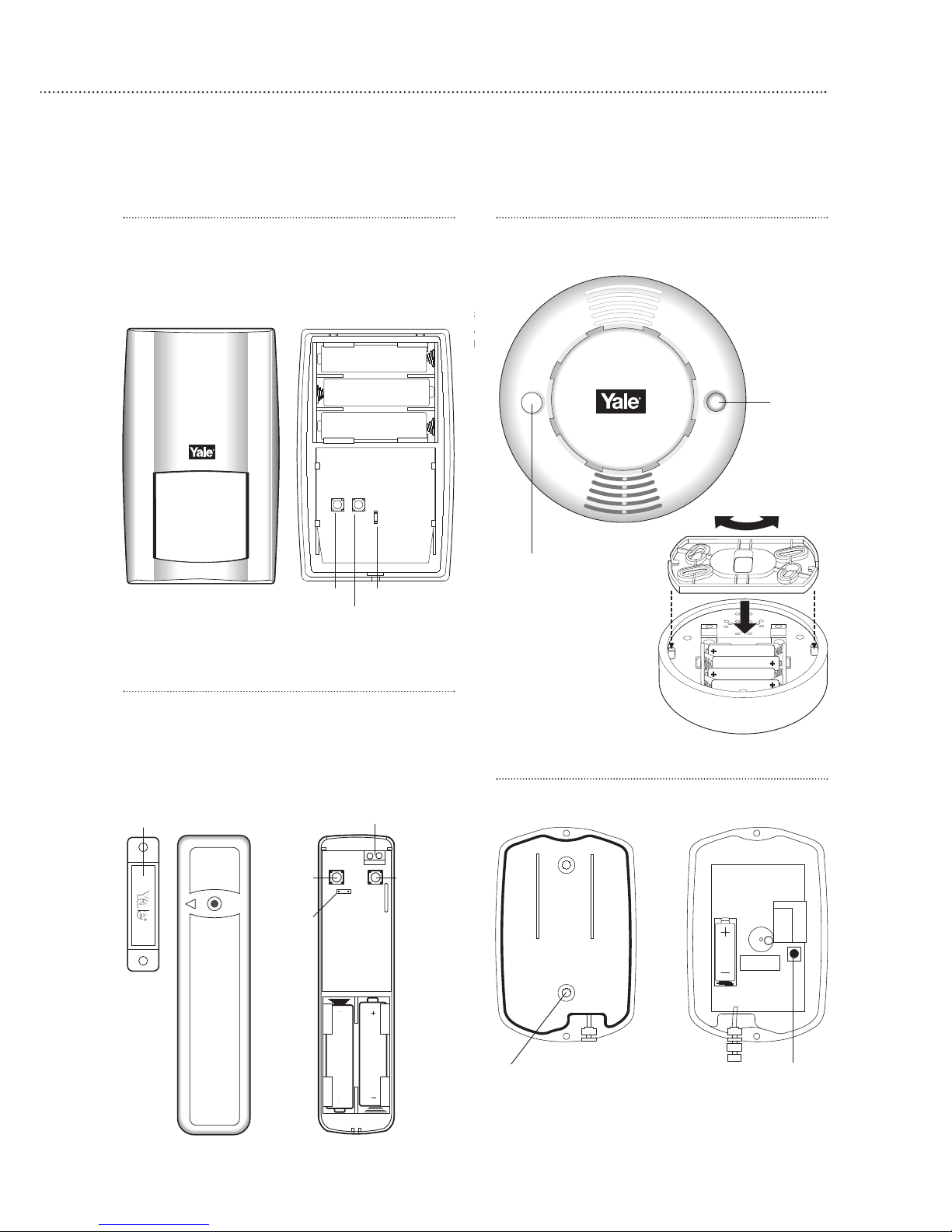
Door/window contact
1 Remove the cover by loosening the fixing screw.
2 Insert the two AAA batteries as shown.
The indicator will flash briefly.
7
+
+
+
3
A
b
Flood detector
Unscrew the two screws and insert 12V battery.
Note: The detector will not respond to inserting the
battery until the learning in procedure is completed.
T
o test the detector is working simply bridge the water
sensor pr
obes with a coin, an inter
nal sir
en will sound.
Tamper
switch
Jumper switch
Learn/Test button
Tamper
switch
Jumper
switch
Extension ter
minals
Magnet
Lear
n/T
est
button
LED
Smoke detector
Twist off the back and insert the 4 AAA batteries
as shown.
Please note that the
LED will flash and can
take up to 11 minutes
to self calibrate.
PIR movement detector
Remove the fixing screw and cover assembly and
insert the three AA batteries as shown.
¥ The light steadily flashes for 30 seconds while
components initialise.
Lear
n/test button
Scr
ew fixing knockouts x 2
Learn/Test
button
Lid
Base
Page 8

7 T
he system asks you for a new PIN code. Think
of one you can remember and key it in. Dont
forget it, write it in System records page 19.
8 Press OK.
9 Confirm by keying in your PIN code again.
10 Press OK. If the incorrect code is entered, a
message prompts the previous step.
11 The display now offers Latch Rpt Off or Latch
Rpt On option.
12
Use the down arrow key to select Latch Rpt Off.
13 Press OK.
14 Enter name of user. You can enter up to 10
letters.
15 Press OK.
16 The screen returns to the PIN Code menu
showing post-programmed status of each user
PIN Code.
17 Proceed to set additional user PIN Codes as
instructed from step 9 - step 18. When done,
press and the display returns to general
settings menu.
Most programming functions work in this way, by
entering your code, selecting from menus and submenus and responding to the prompts.
¥ During entering the PIN code press the button
to clear the screen and enter new information.
¥ Press to return to a previous menu.
¥
T
o return to Alarm off in normal mode, keep
pressing repeatedly.
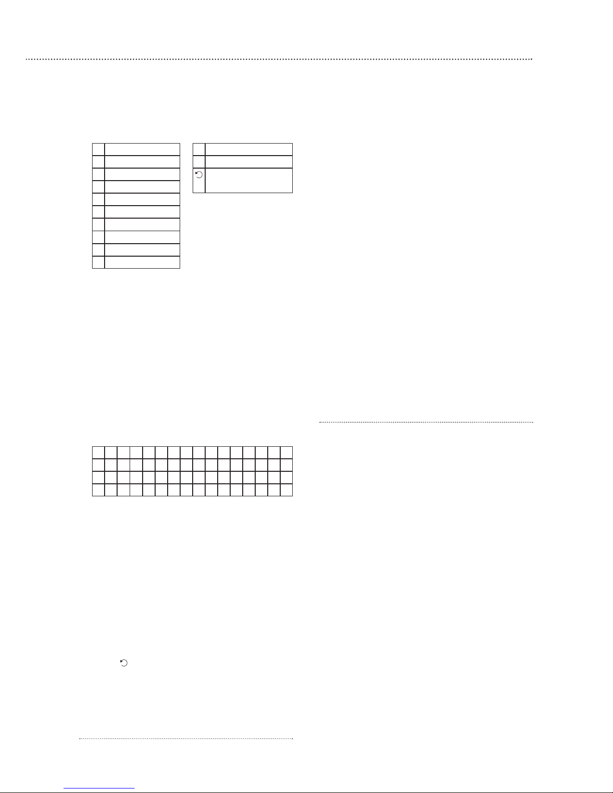
User naming
Each individual User can be given a name for
easy recognition when understanding system
events. User Names can be named when first
setting them or by editing them afterwards when
resetting them, the procedure is similar for both
situations.
¥ When the Enter New Name screen is displayed
the keypad can be used to enter text. Simply
locate the corresponding numeric keys to the
desir
ed alphabet symbols and press repeatedly
until the wanted alphabets/symbols appear.
Release the key and the flashing cursor
automatically jumps to the next position for you
to continue with the next letter by the same
method.
¥
The keys have the following functions:
3
8
Easy install programming
The easiest way to get to know your system and get it up and running quickly is to get
all the devices and accessories programmed
before locating and mounting them.
Control panel
When the power is connected to the control
panel a long beep will sound and Alarm On will be
displayed on the first line and 00:01 01 Jan
displayed on the second line of the screen
indicating the system is armed in Away mode.
Disarm
To deactivate the alarm to enable you to
programme the system.
1 Key 1, Enter Code is displayed.
2 Key in 234 to complete the preset factory code.
Please note that if you fail to put the code in
within 30 seconds the system will default back to
alarm mode and the process will need to be
repeated but entering the code 1234.
3 Press OK and the display will show Alarm off and
the default time and date.
4 The system is now disarmed.
¥ If no code has been entered for a while, the
display will revert back to the original screen.
Introduction to programming
Entering a new PIN code will introduce you to the
ease of programming the system.
Set your PIN code
The contr
ol panel of
fers 3 levels of security;
¥
6 User PIN Codes to enable each member of the
family to use their own unique code.
¥ A program code to enable the user to enter the
programming menu.
¥ A Temporary Code.
1 Press # (program key).
2 Enter 1111.
3 Press OK.
Program menu/Make a Selection appears
briefly, which is then replaced by a list which can be
scrolled up and down using the arrow keys. The
action to be selected has a pulsing symbol
alongside.
4 Use the down ar
row key to select General
Settings.
5 Press OK to select this sub-menu.
The first item in this list is Pin Code which we
require.
6 Press OK to program first PIN code.
Page 9
9
¥ When the name is complete, press OK to
confirm and return to the previous or main menu.
Note The name can be erased by clearing the
display by entering backward spaces and pressing
OK
To delete User PIN code
¥ Except User #1 which is activated by factory
default and cant be deleted in any way, User #2,
3, 4, 5 and 6 PIN code can be deleted by
following the steps below:
1 Move the cursor to the item Pin Code then
press OK the following screen will show the
status of each User PIN code:
2 Move the cursor to the desired # (2~6) of
programmed user PIN code to be deleted, then
press OK.
3 Press OK and the screen returns to previous
one with the deleted User PIN code marked with
¥¥¥¥
To edit User PIN code
¥ All 6 User PIN codes can be edited freely by the
following steps:
1 Move the cursor to the item Pin Code then
pr
ess OK the screen will show the status of
each User PIN code.
2 Move the cursor to the desired # (2~6) of
pr
ogrammed user PIN code to be
deactivated/deleted, then press OK.
3 Press key, the next screen will ask you to
enter your new PIN code and r
epeat it for double
confirmation.
4 Follow the same steps as described in Set you
own pin code to edit
Setting Temporary code
T
he Temporary code is used to arm/disarm the
system for a temporary user and is valid only once
per Arming and once per Disarming. Afterwards, the
Temporary Code is automatically erased and needs
to be reset for a new Temporary user.
¥ The Temp. Code consists of 4 digits and is not
activated as default by the factory.
To set Temporary code
1 Use the arrow keys to select Temp. Code and
press OK
2 You can key in your preferred 4~digit number and
then press OK
3 You are prompted to re-enter the same code
again and press OK.
4 The display now offers Latch Rpt Off or Latch
Rpt On options.
5 Press 5 6 keys to select your option and
press OK. The screen returns to General
Setting menu, setting the Temporary Code is
completed.
Note There is no User Naming feature for Temp.
Code.
Latch Reporting explained
This facility reports arming and disarming of the
system by individual user
, this allows you to check
who and when someone entered or left the house.
This is especially useful to confirm when children
arrive home after school. This information is
displayed on the monitor screen of your Intamac
home manager account. Please see the Intamac
home manager user guide Monitoring Your Alarm
System.
Safe At Home Service
The Safe At Home Service from intamac will send
a message when chosen users enter the house and
disarm the system, please see the accompanying
Intamac literature.
Note Each latch r
eport will incur a minimum call
cost.
Add the door/window contact
11 * *
2 2ABCabc # #
3 3DEFdef Delete character
4 4GHIghi and backspace
5 5JKLjkl
6 6MNOmno
7 7PQRSpqrs
8 8TUVtuv
9 9WXYZwxyz
0
0<space>/-&.+
1 )
M RSMI TH
2
)
M
RS . SMI TH
3)******
4) . .. . ..
Page 10

10
1 P
ress # (program key), enter your prorgam code
and press OK.
2 Select Devices +/- by
scrolling down the
program menu and
press OK.
3 Select Add Devices
and press OK.
¥ Display will show Push
Button On Device to
Add.
4 Press the learn/test
button in the rear of the door/window contact.
¥ The control unit will show it has detected the
device by displaying Detected: (Ok?) Door
Contact.
5 Press OK.
6 You are prompted to select a zone. The control
unit displays all the zones available (zones where
no device has been added), with the cursor
flashing at the first free zone (in this instance
zone 1), press OK.
¥ Each device is given a zone number so that the
control unit can indicate the source of an alarm.
¥ Door/window contacts can be used in various
applications to suit your needs, eg home omit
(see Further door/window contact programming
page 22). As most systems require a detector on
the point of entr
y
, for this example the
door/window contact is programmed as an entry
detector. When used as an entry detector, with
the system armed the door/window contact will
start an entry countdown upon activation, giving
you time to disarm the system.
7 Select Entry from the list displayed and press
OK.
8 Enter Front Door (see User Naming on page 8)
and press OK, (if name not required press OK
without entering text).
9 The display now shows selected settings: DC
Front Door E - door/window contact
programmed into zone 1 as an entry point and
located on the fr
ont door.
10
Press OK.
¥ Press to return to previous menu.
¥
To return to Alarm off (normal mode), press
repeatedly.
Add the PIR movement detector
1 Select Devices +/- by scrolling down the
P
rogramming menu and press OK.
2 Select Add Devices and press OK.
3
Press the learn/test button
the rear of the PIR.
¥ The control unit will show
it has detected the device
by displaying Detected:
(Ok?) PIR sensor.
4 Press OK.
5 You are prompted to
select a zone. The cursor
will flash at the next
available zone (in this instance zone 2), press
OK.
¥ As with the door/window contact, PIRs can be
used in various applications to suit your needs
(see Further programming page 21). For this
example the PIR is programmed as a Burglar
detector. When used as a burglar detector, when
the system is armed and the PIR activated, the
alarm will sound instantly.
6 Select Burglar from the list displayed and press
OK.
7 Enter Hall (see User Naming on page 8) and
press OK, (if name not required press OK without
entering text).
8 The display now shows selected settings: IR Hall
B - PIR programmed into zone 2 as a burglar
detector and located in the hall.
9 Press OK.
10
Press repeatedly until display shows Alarm Off.
Add the smoke detector
When the batteries are first inserted, wait for up
to 11 minutes for the detector to finish its
self-calibration process. When this has finished the
detector can be learnt-in as normal.
1 Enter the Devices +/- menu and select the Add
Device sub menu.
2 When prompted by the control unit, press the
learn test button once on the smoke detector.
3 Assign a zone number to the smoke detector
.
4 Enter location name if required.
5 Press OK to confirm.
¥
The smoke detector will indicate a fire by
sounding the built-in siren, lighting the LED, and
signalling the system to alarm.
¥
The smoke detector will produce a warning beep
and the LED will flash every 30 seconds if the
batteries are near exhaustion.
¥ The learn/test button can be used to test the
smoke detector. With the control unit in walk
test, pr
ess the lear
n/test button, the detector will
Learn/Test
button
Learn/
Test
button
Extension terminals
Page 11

11
s
ound a two-tone confirmation and the control
unit will confirm. Please ensure that you test
smoke detectors regularly.
Add the flood detector
1 Enter the Devices +/- menu and select the Add
Devices sub menu
2 When prompted by the control unit, bridge the
water sensor probes with a coin so that a
continuous alarm can be heard and then press
the learn button on the printed circuit until 3
beeps are given.
3 Assign zone number and press OK.
4 Enter zone location if required.
5 Press OK.
Use of jumper switches
Some devices have internal switches, or
jumpers, which control working modes, or offer
additional programming. The jumpers are either on
or off . On is when the jumper connects two pins,
off when it is removed. It can be parked on one
pin as shown.
Add the siren unit
WARNING
The siren is very loud, be prepared! Take care
not to activate the siren tamper switch
unnecessarily.
The siren is
programmed by the
jumper switches in the left
hand compartment.
1 Lift of
f jumper number
1 and park it. The siren
will beep and flash. The
sir
en is now in learn
mode.
2 Lift off jumper 5 and park it. This must be left in
the of
f position permanently.
¥ If jumper 3 and jumper 4 are removed during the
learning-in process, the siren will only be
activated for 1 second if accidently activated and
Jumper in
‘of
f’ ‘parked’
position
Jumper in
‘on’
position
i
s useful for testing. Ensure the jumpers are
placed into the positions desired before replacing
the cover.
3 Program the control unit by selecting Devices
+/- menu, then Program Siren menu, then
Learn Siren.
4 Press OK and the unit will give a long beep to
confirm - the siren will also respond by a beep
and a flash.
5 Replace jumper 1 to the on position, the siren
will beep and flash to confirm.
6 To ensure siren does not activate, disable the
tamper switch by selecting Program Siren menu
on the control unit, then Siren A/T Off, and
press OK.
¥ The siren disable tamper will automatically revert
to on after about an hour if not switched back on
again manually by selecting Siren A/T On.
¥ Press to return to a previous menu.
¥ To return to Alarm off in normal mode, keep
pressing repeatedly.
Further siren programming
The siren can be configured to your personal
requirements by the use of jumpers.
Siren jumper programming
Jumper positions
J7 on = jamming detection off;
off = jamming detection on
J6 on = normal, J6 off = clear memory
J5
on = stand alone operation, not used in
this system;
off = slave operation
J3 on, J4 on = 3 minute sir
en on period
J3 off, J4 on = 5 minute siren on period
J3 on, J4 off = 10 minute siren on period
J2
on = LEDs on during siren period;
off = LEDs remain on (after an alarm) until
system is disarmed
J1 on = normal; off = learn-in mode
¥
Jumper 5 must be left in the of
f
position.
¥
J6 must be left on in nor
mal ser
vice other
wise
the sir
en will lose its lear
n-in memory when the
batteries ar
e r
eplaced.
J1
J2
J3
J4
J5
J6
J7
Jamming detection
Clear memory (leave On)
Standalone mode (leave Off)
Siren activation time
Siren activation time
Learning-in mode (leave On)
Strobe activation mode
Page 12

12
¥
With J7 off, jamming by radio interference is
detected when continuously present for more
than 30 seconds and activates the siren only
when armed.
7 Replace the battery and electronics compartment
covers, ensuring the gasket between the
electronics compartment and cover is correctly
located and the wires placed in their slots to
ensure a good seal from the environment.
Tamper alarm
If the siren detects a tamper condition it will
activate the siren for the programmed period. If the
tamper condition persists the siren will sound a
series of five pips either every time the system is
armed or when the tamper is enabled, to indicate
the condition.
Confirm Programming
The siren can be programmed to produce
additional confirmation beeps to tell you when the
system is armed and disarmed from outside the
premises. One beep for armed or home armed, two
beeps for disarmed.
1 Program the control unit by selecting Device +/-
menu, then Program Siren menu, then Confirm
On.
2 Press OK and the unit will give a long beep to
confir
m - the sir
en will also respond with a beep.
Zone already allocated
Each device can only be given one zone number.
When a sensor is added to the system for a second
time (without removing first) an error message is
displayed and then the screen will prompt new
action.
Remove a device
If a faulty sensor needs to be replaced, it first
needs to be removed from the control units
memor
y.
Adding a new sensor to a used zone is prevented
u
ntil the previous sensor is deleted. To delete a
sensor, choose Remove Device in the Device +/-
menu, all the used zones with the sensor names are
listed.
1 Use arrow keys to move the cursor to the
position where the device listed is to be deleted.
¥ The list is displayed in zone number order.
2 Press OK. The selected device will be displayed
for you to confirm.
¥ Press to exit if you do not want to delete this
device, the screen will return to the previous list.
3 Press OK to delete.
Radio jamming
This control unit and siren are equipped with the
latest type of radio receiver using AM radio
technology. If interference detection is set to on in
the siren, when the system is armed, any criminal
attempt to prevent (or jam) the detector
transmissions will be picked up as interference and
will cause the siren to alarm. The control unit can be
set to display and report (by dialling out, not
sounding alarm) when interference is detected.
If the alarm is frequently triggered by interference
there may be high levels of unusual radio signals in
your area. Some kinds of electronic equipment can
generate this kind of radio interference.
In the unlikely event of you experiencing pr
oblems
with interference, it is recommended that you switch
jamming detection off.
Please telephone our helpline if you require any
further assistance.
Page 13

13
Installation/mounting
WARNING To prevent the alarm from activating during installation, the siren must have its
tamper disabled and the control unit must be in Walk Test/Program mode.
4
Mounting methods
Yale provide two methods of mounting. Choose
either the self adhesive pads or the screws and wall
plugs supplied.
Self adhesive installation for door/window contact
Clean the surface with a suitable degreaser.
Remove the protective covering from one side of
the double sided adhesive pad and firmly apply to
the back of the device. Next remove the other cover
and firmly press the item onto the desired location.
¥ Do not use the adhesive pad method of
installation on a surface with peeling or cracked
paint, or on a rough surface.
Screw mounting
Remove the front of the device, and, if necessary,
break through the appropriate knockout (where the
plastic is thinner).
Using the holes as a template, drill holes in the
surface and insert the wall plugs if fixing into plaster
or brick.
Siren
WARNING: The siren is
extremely loud!
The tamper switch
plunger protrudes through
the back of the unit, so
that if the siren is pulled
from the wall the alarm is
activated. Ensure it is fully
depressed when the siren
is mounted. If there is a
gap, pack with a suitable
spacing material.
1 Find suitable location, as
previously described in section 2.
2 Disable the tamper switch by selecting Program
Siren menu on the control unit, then Siren A/T
Of
f , and press OK.
3 Using the large screws
provided, mount on
wall thr
ough the base
plate
mounting holes
shown.
4
Fix the sir
en cover with
the securing screw.
5 Enable tamper switch
by selecting Program
Siren menu on the
control unit, then Sir
en
A/T On, and pr
ess OK.
6
Test by arming and disarming with the control unit. If
5 pips sound the tamper is not cor
r
ectly set.
Control unit
Using the four holes of
the wall mounting cross
bracket as a template, mark
the positions of the holes.
Drill four holes and fix the
screws and plugs provided.
Screw the bracket to the
wall. Hook the control unit
onto the bracket.
Ensure the control unit is
fitted at approximately chest height where the
display can be easily seen and the keypad
convenient to operate.
PIR movement detector
The PIR has a built-in sleep timer to save battery
power. If there is no movement in front of the PIR for
1 minute, the PIR will become ready to signal and
any movement will now be reported. The PIR will
sleep for 1 minute after. Any movement detected in
sleep time will not be reported and will extend the
sleep period by 1 minute.
Ensure the test/normal mode jumper switch is in
the test on position. This reduces the sleep time to
a few seconds and enables the LED to flash every
time movement is detected.
1 Screw the rear case to the wall
using the appropriate
knockouts, as described in
Mounting methods. The case
has angled back edges for neat
corner mounting. If mounting in
a corner take care not to bend
the rear case. Screw the PIR
front on.
2 Walk around the protected area
noting when the LED flashes
and check that the detection
coverage is adequate.
¥
Remember to wait a few seconds after the PIR
has detected movement.
¥ Do not try to test the detection pattern by
walking straight up to, or away fr
om the detector,
walk across the field of view.
3 When you are satisfied with the detection
coverage, r
emove the PIR, place the jumper in
the normal off parked position and screw the
PIR back on to its case.
¥ With the jumper in the normal position the LED
will not normally light unless there is a problem,
either a low batter
y or a tamper condition.
In the event of a low batter
y
, r
eplace the
exhausted batteries with fr
esh alkaline
r
eplacements.
T
amper switch plunger
must be pressed in fully by
wall surface
Fixing holes x 4
Corner fixing
holes x 4
Surface fixing
holes x 2
Page 14

14
¥
Do not position a PIR to look directly at a door
protected by a door contact, this could cause the
door contact and PIR radio signals to be
transmitted at the same instant when entering,
cancelling each other out.
¥ Ensure the jumper is in the normal off position
when testing is finished, otherwise low battery
and tamper conditions will not be shown.
Door/Window contact
1 Ensure the jumper
switch is in the test
on position.
¥ In this position the
indicator light will
illuminate every time
the door contact is
operated.
2 Fit as described in
Mounting methods,
mounting the
detector base on the
frame and aligning
the magnet by the
arrow as shown.
¥ The magnet should not be more than 8mm from
the detector when the door is closed.
¥
Ensur
e the tamper switch spring is positioned so
that it makes contact with the mounting surface
through the tamper switch aperture.
¥ If the door contact cannot be mounted on the
door frame, use the HSA3090 multiple
door/window contact accessory kit with a length
of wire to mount the door contact remotely (see
page 17).
¥ When fitting to a window, fix the magnet to the
moving part and the detector to the frame.
3 Fix the detector on its base and secure with
s
crew. Test it by opening and closing the door or
window. The light will flash when an open
condition is detected.
4 Remove the detector, put the jumper switch in
the normal off position. Screw the detector back
onto its base.
¥ When the jumper is in the normal off position
the indicator light will normally be off. It will only
light if there is a problem, either a low battery or a
tamper condition.
¥ Ensure the jumper is in the normal off position
when testing is finished, otherwise low battery
and tamper conditions will not be shown.
Smoke detector
1 Unscrew the fixing plate from the smoke detector
by turning the plate anticlockwise.
2 Using the two holes of the
ceiling mounting bracket as a
template, mark the position of
the holes.
3 Drill 2 holes and fix into place
with the 2 screws and plugs
provided.
4 Hook the smoke detector onto
the bracket and secure by
tur
ning in a clockwise dir
ection.
Flood detector
1 Use the two fixing holes on the product as a
template, mark the position of the holes.
2 Drill 2 holes and fix into place with the 2 screws
and plugs provided.
Installation is complete.
Door/
Window
Frame
Align
8mm (max)
Surface fixing
holes x 2
Page 15

PIR sleep feature
The PIR has a built-in sleep timer to save battery
power. If there is no movement in front of the PIR for
1 minute, the PIR will become ready to signal and
movement will now be reported. The PIR will sleep
f
or 1 minute after. Any movement detected in sleep
time will not be reported and will extend the sleep
period by 1 minute.
Walk test
This allows you to test the system without
causing an alarm.
1 Press # followed by your Program code.
2 Press OK.
3 Select Walk Test.
4 Press OK and wait for control unit self test period
to finish.
¥
Walk around protected areas in front of PIRs and
open doors/windows protected by door contacts.
¥ If the control unit receives a signal, it will sound a
chime and the display will show the sensor and
zone number which has been tested.
¥ The message will be displayed until being
r
eplaced by another test signal.
¥ Pressing the key, will return to programming
menu.
¥ If left in walk test, the control unit will revert back
to Alarm off after 5 minutes.
Testing the siren
The siren can be tested by arming and disarming
the system, the siren will respond as follows:
¥ When the control unit is armed the siren will beep
once (if siren confirm is switched on) and will flash
after the Exit delay period has expired.
¥ When the control unit is disarmed, the siren will
give two short beeps (if siren confirm is switched
on) and will flash from side to side twice.
Testing the system
Testing the system should be done on a regular basis and after any alterations.
15
5
Page 16

6
16
Connecting to the Intamac Home Monitoring
TM
service
Connect to the online home monitoring and messaging service, with your free
12 months subscription.
Call or register online with Intamac
Telephone Intamac on 0845 230 0708 during
working hours (Mon-Thurs 9am-5pm, Fri 9am-4pm)
or register online. You will need to provide the
information listed in the Intamac home user guide
Registration Information Table on page 3
Upon verification, Intamac will then provide you
with your account number and a password/username
to log onto your secured Internet area.
To complete the connection to the Intamac Home
Manager“ se rvice you will need to input your
account number into the control unit.
1 Press #.
2 Enter Program Code.
3 Press OK.
4 Select General Settings.
5 Scroll down using arrow keys to Acc. Numbers.
6 Press OK.
7 Insert your unique account number.
8 Press OK.
9 Scroll down to Rpt On/Off.
10
Press OK.
11
Select Reporting On.
12
Press OK.
Please r
efer to the Intamac Home Manager“
user guide on how to make full use of this service
and if the connection has been successfully made.
Connecting your alarm - Telephone connection
A telephone lead and 2-way adaptor is included
so you can have your telephone and the control unit
connected to the telephone network at the same
time.
1 Plug the 2-way adaptor
into the telephone wall
socket.
2 Plug one end of the
telephone lead into the
control unit and the
other end into the
adaptor.
3 Plug your telephone
into the 2-way adaptor.
¥ The control unit will not be able to telephone out
if any handsets are accidently left off, or if
someone is ringing in.
¥ If you are using an answer machine on the same
telephone line as the system please ensure that
the answer machine is not set to respond to
incoming calls on the first ring.
¥ If you do not wish to use the monitoring features
of the system it is not necessary to connect the
telephone lead to the control unit.
Page 17

17
Arming the system
Away arming
1 Enter your PIN code and press OK.
2 Arm and Home can be selected by using the
arrow keys, select Arm.
3 Press OK. The exit delay is displayed and counts
down from the default setting of 30 seconds. The
control unit beeps (unless exit sound has been
switched off).
4 When the time is up, the control unit sounds a
long beep. Alarm On is displayed and the
system is armed.
¥ The siren will beep once (if siren confirm has
been switched on), and the strobe will flash once
after the Exit Delay has expired.
Home arming
1 Enter your PIN code and press OK.
¥ You have a silent exit period in which to vacate
the armed area. This exit period is the same as
used when fully arming.
2 Press t to move the cursor down to select
Home.
3 Press OK.
¥ You can also put the system into the home mode
by using the keypad or keyfob accessory.
Stopping the exit delay
Do this by disarming the system.
1 Press .
2 Enter the PIN code.
3 Press OK.
Alarm Off will be displayed and the system
returns to disarmed mode.
Partial (by-pass) arm mode
The Partial (By-pass) Arm mode allows the user
to de-activate (by-pass) any sensors at their
discretion. This feature allows your home to be
ar
med yet the person inside the house can move
freely in the area where the sensor is by-passed.
1 Enter your PIN code and pr
ess OK within 10
seconds.
2 Press 6 to move the cursor down to select
Bypass.
3 Press OK.
4 All the zones are listed in zone number order.
5 Press 6 , 5 keys to select the zone to be by-
passed.
6 P
ress OK to confirm the selection. The selected
zone will be marked with a * character in front
of it to indicate that device is to be by-passed.
Note The zones can be toggled between
by-passed and not by-passed by pressing the
OK key repeatedly followed by the * character
appearing for By-pass setting and *character
disappearing for By-pass unsetting.
7 You can repeat Step 5 ~ Step 6 to continue
selecting the device to be by-passed.
8 After all the sensors to be by-passed have been
selected, press to return to user menu and
the cursor stays at Arm.
9 Press OK to select Arm and to arm the
system.
Note If a censor is by-passed, then the Control
Panel will not respond to its triggering Arm mode
¥ The by-pass setting is effective for only one time,
once the system is disarmed, the by-pass setting
is cleared automatically.
¥ When a sensor is by-passed, the system can be
armed directly regardless of its fault situation (if
any). However, its fault situation is still being
monitored and will be logged and displayed
when you access theLog.
Disarming the system
1 Enter your pin code.
2 Press OK. The control unit will sound 2 short
beeps and disarm.
¥ The siren will beep twice (If siren confirm has
been switched on) and the strobe will flash from
side to side after the system has been disarmed.
Alarm activation
If a sensor is triggered when armed, or if an entry
period is left to expire, the control unit will activate
the alarm immediately, while if a Home Omit sensor
is triggered, the control unit will not respond if in
home mode.
If a 24-hour alar
m, fire alarm, personal attack,
alarm tamper or medical emergency is triggered,
the control unit will activate the alarm immediately
ir
respective of what armed mode the control unit is
in.
During an alarm, the control unit will sound the
sir
en and contact the monitoring station.
If a tamper alarm is activated when the panel is
disarmed the system will dial out, and the siren will
be on but the alarm message will not be displayed.
Stopping the alarm
A flashing ALARM! will be displayed and the
Using the system
Arm and disarm the system and practice using it. Trigger the alarm by arming the system
and opening protected doors/windows and walking past PIRs. Now is the time to show the
rest of the family how simple it is to use. The telephone features are yet to be programmed.
7
Page 18

18
s
ystem will sound an alarm.
1 Key in your PIN code, and then press OK, the
audible alarm will stop.
¥ If the alarm is silenced before reporting has
finished the control panel will show Reporting
- - - pls wait and you will be prompted to press
OK to carry on, when the reporting is finished.
2 The control unit will then show alarm log, press
OK to clear and reset.
If an alarm is silenced using a remote keypad or
keyfob, the system will only be silenced and
disarmed. The system can only be reset to resume
normal operation after an alarm event at the control
panel.
Alarm memory
If an alarm was raised during your absence, and
the alarm sequence has been carried out, the
screen will continue to show ALARM!
When you come back and disarm the system the
siren will sound a 3-second alarm instead of the
normal 2-beep sound.
To clear the display, follow the same steps as
stopping the alarm described above.
Warning If the siren is activated for 3-seconds
when you disarm your system there could be an
intruder still in your premises.
Force Arming
When you try to arm the system by Entering the
PIN Code, if any fault situation has occurred before,
the display will show Fault Dsp and a list of faults
will be shown when OK is pressed.
¥ If you move the cursor to Away Arm position
and then press OK, the Control Panel will sound
a ding-dong warning sound to indicate arming is
prohibited, and the message Fault DSP is
displayed in the middle of the top display row
and alternate at 2-second intervals with individual
fault events
Note In the same situation, if you ar
m the
system by pressing the Arm button on the Remote
Controller, the Control Panel will response in the
manner as described above the ar
ming is also
prohibited.
¥ At this moment, you can first rectify all of the
pr
oblems and then clear the Fault display
(Please see section XI In a Fault Situation), and
t
hen afterwards you can arm the system
¥
However if you want to put the system into Arm
mode with the fault situation persisting, it is still
possible by following the procedures below.
1 Enter your PIN code and press OK.
2 You will be prompted to see if the forced arm is
OK, to confirm press OK again.
3
The exit delay is displayed, when the time is up,
the control panel sounds a long beep. Alarm On
is displayed and the system is armed.
Event Log
The alarm memory remembers the last 20
system events including
All Alarm Events with Device ID
All Fault Warning Events
All Arming And Disarming Events
¥ The logged events are display in reversed
chronological order, (most recent event first).
¥ The log is marked with a Start label before the
most recent entry and End after the oldest
entry.
¥ To View Log:
1 Key in the user code and press OK while in
Disarm mode to access Users Menu
2 Press the 6 key repeatedly to select Log and
then press OK and the start of the log will be
displayed.
3 The log can now be scrolled up and down and
viewed with the 5 , 6 keys. The most recent
event will be at the start.
4 An example of logged event is given below
where the first line tells the time and date of the
event, the second line tells the type of event and
the third one either states the User or the device
that caused the event. Abbreviation as DC
stands for Door contact, LB is short for low
battery, Tamp means Tamper where Rest is
short for restore.
Tamper display
The control unit will identify the device triggering
Page 19

19
a
tamper alarm when the system is disarmed. To
enable the display to be cleared a tamper condition
has to be rectified. For example, if a detector has
been tampered the display can only be cleared
once the detector tamper has been closed. The
display is cleared by entering your PIN code,
pressing OK, and exiting the Arm Home display by
pressing .
Please note that detector tampers will trigger an
alarm even when the system is disarmed. If you
wish to take down a detector that has tamper
protection ensure the control unit is in Walk Test
mode.
Low battery display
When a detectors batteries are running low, it will
s
ignal its condition to the control unit when it is
activated. To be able to clear the display the
batteries in the detector will have to be changed.
Always use alkaline batteries as replacements and
ensure the control unit is in Walk Test when taking
down detectors. After changing batteries, once the
detector is activated (out of Walk Test mode), the
display can be cleared as described in Tamper
display.
Page 20

8
20
Configuring your system
Fine tune the operation of the control panel to your requirements; advanced programming
for PIRs and door/window contacts.
General settings menu
Pin code
To change PIN code, follow steps in Easy install
programming.
Temporary code
To change Temporary code, see steps in Easy install
programming section page 8.
Duress code
To change Duress code, see steps in Easy install
programming section page 8. This code will arm and disarm the
system as normal, but will signal a personal attack alarm to
Intamac.
Programming code
To change Programming code, see steps in Easy install
pr
ogramming section page 8. This code provides access to all
the programming functions of the alarm, so it must be kept
secure.
Away entry time
Enables you to alter the entry delay time. Options available are
0 sec., 10 sec., 20 sec., up to 70 sec. in 10-sec increments.
1 Use the arrow keys to switch between options.
2 Press OK to confirm.
Note: 20 sec. is set as factory default.
Entry delay time applies only to the zone that a door contact
or PIR is installed and is set to entry point.
Away exit time
Enables you to alter the exit delay time. Options available are
0 sec., 10 sec., 20 sec. up to 70 sec. in 10-sec increments.
1 Use arrow keys to switch between options.
2 Press OK to confirm.
Note: 30 sec. is set as factory default.
Home entry time
Enables you to alter the entry delay time. Options available are
0 sec., 10 sec., 20 sec., up to 70 sec. in 10-sec increments.
1 Use the arrow keys to switch between options.
2 Press OK to confirm.
Note: 20 sec. is set as factory default.
Entry delay time applies only to the zone that a door contact
or PIR is installed and is set to entry point.
Home exit time
Selects the time delay to allow leaving the protected area of a
house when home arming. Zer
o (no delay to 70 seconds can be
selected in 10-second intervals.
1 Use the arrow keys to switch between options.
2 Press OK to confir
m.
Note: 30 sec. is set as factor
y default.
Control unit siren on/off
Enables you to set the contr
ol unit sir
en (not exter
nal sir
en) to
be silent in the event of an alar
m.
1 Press arrow keys to select the option.
2 Press OK to confirm.
Note: Siren ON is set as factory default. It is recommended
that the control unit siren is left on.
Away exit sound
Switches on, off and the volume of the exit countdown beeps
during the exit period when away arming.
1 Use arrow keys to switch between options.
2 Press OK to confirm
Note: Low volume is set as factory default.
Away entry sound
Switches on, off and the volume of the entry countdown
beeps during the entry period when entering the house. The
system must be disarmed during this period otherwise an alarm
will start.
1 Use arrow keys to switch between options.
2 Press OK to confirm.
Note: Low volume is set as factory default.
Home exit sound
Switches on, off and the volume of the exit countdown beeps
during the exit period when away arming.
1 Use arrow keys to switch between options.
2 Press OK to confirm
Note: Low volume is set as factory default.
Home entry sound
Switches on, off and the volume of the entry countdown
beeps during the entry period when entering the protected area
of the house when home armed. The system must be disarmed
during this period otherwise an alarm will start.
1 Use ar
r
ow keys to switch between options.
2 Press OK to confirm.
Note: Low volume is set as factory default.
Door chime
Switches on, off and the volume of the door chime in the
control unit when an entry sensor is activated.
1 Use arrow keys to switch between options.
2 Press OK to confirm.
Note: Door chime volume is set to low as factory default.
Time
Allows you to set the cur
r
ent time (hours and minutes).
1 Hours will flash, use arrow keys to select the hour, 24-hour
for
mat is used.
2 Pr
ess OK to confir
m the hour setting.
3 Now the minutes will flash, use arrow keys to select the
minutes.
4 Pr
ess OK to confir
m.
Note: Time will have to be reset if all power to the unit is lost.
Date
Allows you to set the current date.
1 Months will flash, use ar
r
ow keys to select the month.
2 Pr
ess OK to confir
m the month setting.
Page 21

21
3 Now the day will flash, use arrow keys to select the day.
4 Press OK to confirm.
Note: Date will be reset if all power to the unit is lost.
Panel siren
A
llows you to set the duration of the siren from disabled
(silent) to 15 minutes in 1 minute steps.
1 Use arrow keys to switch between options.
2 Press OK to confirm.
Note: The factory default is 3 minutes.
Siren Delay
Allows you to delay the siren sounding for a set period of time
to enable the monitoring service to be called prior to notifying
intruder that the alarm has been activated.
1 Press arrow keys to select the option.
2 Press OK to confirm.
3 Select whether you want the siren delayed by up to 10
minutes or disabled.
Note: The factory default is disabled.
Keyfob remote control entry enable
Turns on and off the remote control disarm function.
1 Press arrow keys to select the option.
2 Press OK to confirm.
Note: Remote Control Entry Enable off is set as factory
default.
When the keyfob remote entry enable is set to off it will not
be possible to disarm the control unit when the system is fully
armed unless an entry point device is activated first. This
feature is used to ensure that the system cannot be disarmed
with a stolen remote control without unlocking a door first.
When the keyfob r
emote contr
ol entr
y enable is set to on,
the keyfob remote can arm and disarm the control unit as
normal without activating an entry point first.
A panic alarm cannot be disarmed by a keyfob r
emote. This
prevents an assailant from silencing a personal attack alarm
by snatching the keyfob and pressing Disarm.
Interference
Allows you to set the control unit to respond to the presence
of radio jamming.
1 Use ar
row keys to switch between options.
2 Press OK to confirm.
Note: Detection Off is set as factory default. Detection On
will enable the display of any inter
ference that is detected for
more than 30 seconds and will notify the Intamac Home
ManagerTMService. Interference will not cause the control unit
to sound an alarm, Radio interference is unlikely, but can
effect the operation of the system. Please read Radio
jamming (page 12) for more information.
Account Number
This is a 5 digit number issued by Intamac that is unique to
your system to identify your control unit when reporting to
Intamac Home ManagerTMSer
vice.
1 Enter 5 digit number.
2 Press OK to confirm.
Note: This number must be entered to allow reporting to the
intamac Home ManagerTMService.
Check-in report
S
ends a monitoring signal every 7 days if no other reporting
has occurred in that period, proving the integrity of the system.
1 Use arrow keys to switch between options.
2 Press OK to confirm.
Note: Check-in reporting is disabled as factory default.
Report On/Off
T
urns on and off reporting to the Intamac Home Manager
TM
Service.
1 Use arrow keys to switch between options.
2 Press OK to confirm.
Note: Reporting is switched on as factory default; this must
be left on if the Intamac Home Manager“ service is required. If
switched off then the system will operate as a standard Bells
only alarm system without telephone reporting.
Check Telephone Line
Switches on and off telephone line monitoring that will alert
you if the line is disconnected for any reason.
1 Use arrow keys to switch between options.
2 Press OK to confirm.
Note: Telephone line checking is switched on as factory
default.
Mobility check
Used to monitor movements of the elderly or infirm when the
system is disarmed or home armed. If no movement is detected
within a chosen inter
val an alarm is sent to the Intamac Home
Manager“ se rvice. Intervals of 4, 8 and 12-hours can be
selected.
1 Use arr
ow keys to switch between options.
2 Press OK to confirm.
Note: Mobility reporting is switched off as factory default.
Open/Close reporting
You can choose between O/C Off, this allows you to select
latch reporting by individual PIN code and keyfob user (see
pages 8, 9 and 23) and O/C On wher
e every Away Arming,
Home Arming and Disarming events are reported to the Intamac
Home ManagerTMservice.
1 Use ar
row keys to switch between options.
2 Press OK to confirm.
Note: Open/close reporting is switched off as factory default.
Further PIR programming
The PIR can be used in four dif
fer
ent ways within the system:
¥
T
o cause an instant alarm upon detection when the system is
fully or home ar
med;
¥
T
o be omitted when the system is home ar
med;
¥
T
o commence an entry countdown upon detection when the
Page 22

a
rmed or home mode
Points for consideration
¥
In home mode, detectors set as Burglar will cause an alarm
when activated, whilst detectors set as Home Omit will not
trigger an alarm.
¥ If the system is fully or home armed, detectors set as Entry
will start the entry countdown when activated. When
disarmed, an entry detector will sound a ding-dong chime
from the control unit (if door chime is selected).
¥ If a detector is set as Home Delay it will start an entry
countdown when the system is home armed. This setting is
useful if your path to the control unit (when used at night) is
vulnerable (a stairwell for instance).
¥
After testing the door/window contact and PIR in your chosen
locations, please ensure that the jumpers are moved into the
off (parked) positions. If left in the on positions battery life will
be shortened and it will not be apparent if the detector has a
tamper or low battery condition.
Multiple door/window contact wiring
If difficulty is experienced fitting the door/window contact
because of space etc, the HSA3090 multiple door/window
contact set should be used (not included).
The magnet/contact pairs are wired using bell wire (not
supplied) to the extension terminals as indicated on page 7. The
knockout in the top of the door/window contact must be
removed to allow the wire to pass through. The total length of
wire used must not exceed 10 metres. The magnet/contact
pairs should be no fur
ther than 8mm apart.
It is possible to use a single pair of multiple door/window
contacts with a detector if you experience problems fitting the
main unit to the door frame.
When using multiple switches on a door/window contact, you
can use the detector without having a magnet alongside the
main unit.
22
system is home armed, but cause an instant alarm when fully
armed;
¥ To commence an entry countdown upon detection when the
s
ystem is fully or home armed.
These choices are presented during the learning in process
and are summarised by the following codes within the control
unit:
B Burglar active when control unit is in
armed or home mode
D home Delay starts entry countdown in home
mode only
E
Entry starts entry countdown when
in armed or home mode
PIR operation
The LED does not normally flash when it senses movement.
This is to conser
ve battery power.
If the LED flashes regularly, it indicates that it has either been
tampered with, or the batteries are getting low and need
replacing.
Further door/window contact programming
The door/window contact can be used in six different ways
within the system:
¥ To cause an instant alarm upon activation when the system is
fully or home armed;
¥ To be omitted when the system is home armed;
¥ To commence an entry countdown upon activation when the
system is home armed, but cause an instant alarm when fully
armed;
¥ To cause a fire alarm when activated whether the system is
ar
med or disar
med;
¥ To cause an instant alarm whether the system is armed or
disar
med (24-hour alarm);
¥
T
o commence an entry countdown upon activation when the
system is fully or home armed.
These choices ar
e presented during the learning in process
and are summarised by the following codes within the control
unit:
B
Burglar active when control unit is
armed or home mode
O home Omit not active when in home mode
A home Access starts entry countdown when in
home mode
F Fire causes fire alarm upon activation
whether system armed or
disarmed
H 24 Hour causes burglar alarm upon
activation whether system armed
or disar
med
E Entry starts entry countdown when in
armed or home mode
Points for consideration
¥ In home mode, detectors set as Bur
glar
will cause an alarm
Knockout
removed for
wir
e
Door/window
switches wired in
series
Magnets
Page 23

23
9
Keyfob remote control accessory
P
rogramming
Learn in the keyfob as follows:
1 Enter the Devices +/- menu and select the Add
Device sub menu.
2 Press the Arm button on the keyfob remote when
prompted and confirm it is the correct detector
by pressing OK.
3
After you have assigned a zone number for the
keyfob remote, you are presented with a choice:
¥ Medical Emg: Control unit dials a medical
emergency alarm when the Panic button on the
keyfob remote is pressed.
¥ Personal Att: Control unit dials a personal attack
alarm when the Panic button is pressed.
4 Press OK. You can now choose latch reporting.
¥ Latch.Rpt.Off: No keyfob reporting of arming
status to the Intamac Home Manager
T
M
Service,
this is set as factory default.
¥
Latch.Rpt.On: This will report every time the Home
is armed, Away armed and disarmed by the keyfob.
5 Press OK. You are now asked to choose a user
number. If latch reporting is used this is needed
by the control unit to identify who is arming and
disarming the system.
¥ User -: This is used if latch reporting is not
required, or if you do not want the user to be
individually identified.
¥
User 1 to User 6: Use arrow keys to choose user
number. If you want to identify a latch r
eporting user
then a number can be assigned. This can be the
same as User PIN code number, for example if
Frank is using PIN code 3456 and is user 3, then
a keyfob can be similarly named Frank and be
assigned user 3 as well. This will identify Frank
every time he arms or disarms with either his keyfob
or 3456 PIN code.
6 Press OK. Enter a name of your choice.
7 Press OK and the display will show your
selection, press OK again to confirm or to start
again
¥ The Panic button has to be pressed for more
than 5 seconds to operate. This is a safety
feature to stop accidental operation.
¥ If programmed as a Personal Attack alarm, an
alarm started by the Panic button cannot be
silenced with the keyfob remote, only with the
control unit. This is a safety feature to stop any
potential attacker disar
ming the system after a
Personal Attack alarm has started.
Using
The system is armed by pressing the Arm or
Home button for at least 1 second (this delay
feature prevents accidental operation).
The system is disarmed by pressing the Disarm
b
utton in the same way.
The switch at the side prevents the keyfob from
transmitting accidentally.
¥ The keyfob can also be used to answer an
incoming telephone call by pressing the Disarm
button twice for 1 second with a pause between
and then to close the call by pressing the Disarm
button again for 1 second.
¥
When arming the system in home mode using the
keyfob remote, the system will arm and disarm
instantly without an exit or entry countdown.
Keypad remote control accessory
Programming
Note before learning in, ensure that J1 has a
jumper link is on the two pins.
1 Enter the Devices +/- menu and select the Add
Device sub menu.
2
When prompted by the control unit enter 0000 on
the keypad then press TEST. The Tx LED will flash
showing that the keypad is in program mode.
3 Press TEST then 1 on the keypad. The keypad
and the control unit will beep.
4 After you have assigned a zone to the keypad,
the display will show the successfully installed
device.
5 Press OK on the control unit.
6 Press Off twice on the keypad to exit program
mode, Tx LED will stop flashing.
¥ The keypad will beep every 30 seconds if the
tamper switch is open. Please ensure tamper
switch closes when mounting.
Using
To arm the system:
Enter your PIN code and press Arm.
To disarm the system:
Enter your PIN code and press Off.
To home arm the system:
Enter your PIN code and press Home.
Adding accessories
To provide additional protection you can add extra door/window contacts, PIRs, keyfob
remote controls, keypad remote controls, help buttons and smoke detectors. These are
available separately from your local stockist.
Page 24

24
Changing the batteries
Always use alkaline batteries as replacements, any other type of battery can cause
problems with the operation of the system. Typical life of batteries is three years. Ensure the
correct steps are taken when changing batteries in tamper protected devices.
Siren
The siren will produce a series of pips when
armed and disarmed, and an interrupted alarm
sound (if activated) if the siren batteries are near
exhaustion. Change the batteries as soon as
possible. The sound will be reset when the batteries
are changed.
¥ You can determine if your siren is sounding a
tamper warning or a low battery warning by
arming and disarming the system. If the siren
produces 5 pips when the system is armed and
disarmed, the batteries are low. If the siren
produces 5 pips, only when the system is armed,
the tamper switch has been disturbed.
1 Before changing siren batteries, the siren tamper
must be disabled by selecting Devices +/-, then
selecting the Program Siren menu and then
Siren A/T Off. Press OK. When these steps are
taken the siren will beep in confirmation.
¥ When changing the batteries allow 1 minute
between taking out the old batteries and
replacing with the new.
Warning After the batteries have been changed
the siren tamper will become active again. To avoid
the siren sounding in alarm, ensure that you follow
the next step before attempting to refit the siren
cover.
2 W
ith the new batteries fitted the sir
en tamper
must be disabled again by selecting Devices +/, the selecting Program Siren menu and then
Siren A/T Off. Press OK.
3 Refit the siren cover.
4 Enable the siren tamper by selecting Siren A/T
On in the Program Siren menu. Press OK.
PIR and door/window contact
The LED will flash every time the device is
activated indicating a low battery and the control
unit display will identify the sensor low battery.
1 To prevent a tamper alarm, in the control unit
select W
alk Test.
2 Remove device from mounting.
¥ Before changing the batteries check that the
tamper switch closes when mounted.
3 Change the batteries with alkaline replacements.
4 Screw device back on.
Keyfob remote control
T
he LED will either be very dim or will not light at
all when the battery is low. Change the battery as
soon as possible with an alkaline replacement.
Keypad remote control
To indicate a low battery the Active LED will
flash repeatedly. The control unit display will also
indicate the low battery condition.
1 To prevent a tamper alarm, in the control unit
select Walk Test.
2 Remove keypad from mounting.
¥ Before changing the battery check that the
tamper switch closes when mounted.
3 Change the battery with alkaline replacement.
4 Screw keypad back on.
Smoke detector
The LED will flash and sounder will beep every
30 seconds to signal low battery. Change the
batteries as soon as possible with alkaline
replacements.
¥ The control unit display will identify the smoke
detector low battery only after activation.
Flood detector
Remove the cover by loosening the fixing scr
ews
and insert a new 12V battery.
Help button
Remove the cover by loosening the fixing screw
and insert a new 12V battery.
Page 25

25
Trouble shooting
Siren
Siren does not respond to arming or disarming
¥ Siren batteries are completely exhausted. Check
siren batteries by removing siren cover, if there is
no tamper alarm when removed, replace
batteries with new alkaline equivalents.
¥ Siren not learnt-in. If siren produces a tamper
alarm when the cover is removed and siren is
OK, learn-in the siren.
Siren produces a 3 second alarm when disarmed
¥ There has been a previous alarm and there might
be an intruder still in the premises.
Siren produces a series of pips when armed or
disarmed
¥ The siren has low batteries. Check that the siren
produces a series of pips when arming and
disarming, indicating low batteries. Change
batteries with new alkaline replacements.
¥ The siren tamper switch has been disturbed.
Check that the siren produces a series of pips
only when arming, indicating a tamper fault.
Check that the siren cover is firmly secured and
the tamper switch plunger is in contact with the
wall. If not use suitable packing material to fill
gap.
Siren produces an interrupted tone when
sounding an alarm
¥ The siren has low batteries. Change batteries
with new alkaline replacements.
Siren will not learn-in
¥ No detectors are learnt-in. Learn-in a detector
first. The siren will not learn-in into a control unit
without a previously learnt-in detector.
PIR
PIR does not respond to movement
¥
Previous movement has triggered the PIR sleep
timer and is preventing subsequent movement
detection. Arm system and vacate protected
r
oom for at least 1.5 minutes before testing.
PIR is slow to respond
¥ This is normal, the PIR has sophisticated false
alarm filtering that will filter out random
fluctuations and r
esponds to genuine movement
across field of view
, it is less sensitive walking
directly towar
ds it.
PIR gives false alarms
¥
Check pets have no access to protected area.
¥ Check that PIR is not pointed at sources of heat
or moving objects, e.g. fluttering curtains.
¥ Check that PIR is not mounted above convector
heaters or pointing directly at windows.
PIR LED flashes when jumper is in normal position
¥ Batteries are low or the tamper switch is
disturbed. Check that the tamper switch spring is
making contact with base. If the tamper switch is
OK, change batteries with new alkaline
replacements.
PIR does not respond to movement when jumper
is in test position
¥ Batteries are completely exhausted. Change
batteries with new alkaline replacements, LED will
flash for 30 seconds while components initialise.
Door contact
Door contact LED flashes when jumper is in
normal position
¥ Batteries are low or the tamper switch disturbed.
Check that the tamper switch spring is making
contact with the mounting surface. If the tamper
switch is OK, change batteries with new alkaline
replacements.
Door contact does not respond to door opening
when jumper is in test position
¥ Batteries are completely exhausted. Change
batteries with new alkaline replacements
¥ The magnet is too far away from the door
contact. Check that the gap between door
contact and magnet is not greater than 8mm.
Control unit
Control unit does not dial out when there is an
alarm
¥
Faulty telephone connection. Check all
connections to the telephone line. Test with spare
telephone handset if necessary.
¥
Ensure the account number issued by Intamac is
programmed and the Rpt On/Off in general
settings menu is set to Reporting On.
Page 26

26
Specifications
All devices
EMC
Tested to EN 300 220-1 and ETS
300 683
Environmental conditions
-10¡ C to 40¡ C, relative humidity 70%
non-condensing for all units except the
external siren. Siren: -20¡ C to 50¡ C,
relative humidity 95% non-condensing
Radio operational range
30m in a typical domestic installation
Can vary depending on building
construction and RF environment.
Housings ABS
Control unit
Keys
t Scrolls display downwards
s Scrolls display upwards
# Pr
ogram button, telephone
dialler
*
Phone number pause
When in programming mode,
clears the screen or return to
previous menu; back space
for telephone numbers
Device codes
DC Door/window contact
PIR PIR movement detector
SD Smoke detector
RC Keyfob remote control
KP Keypad remote control
WTR Help watch
Control unit illumination Display is back lit
when the unit is mains power
ed.
Housing ABS
Siren Output 95dBA sound pressure @
1m minimum
Zones 20 radio devices
Radio system 433.92MHz AM Integral
transmitter and super heter
odyne
receiver with jamming detection
Power supply Plug top adaptor type, input
230V
AC 50Hz, output 9VDC, 500ma,
tested to EN 60 950
Rechargeable battery Ni-MH, 1200mah,
char
ge time 48hrs
T
elephone interface Tested to TBR 21.
Hands free vox operated, 6
programmable numbers
REN rating 1
Siren
Siren output 104dBA sound pressure @
1m minimum
Radio 433.92MHz AM super heter
odyne
receiver with jamming detection
Power supply 6V, 4 x D alkaline cells. 3
years minimum typical ser
vice life
PIR movement detector
Alarm processing Micr
oprocessor
controlled dual edge sequential pulse
count with pulse length discrimination
Radio 433.92MHz AM transmitter
Power supply 4.5V, 3 x AA alkaline cells. 3
years minimum typical domestic service
life, 1-minute sleep timer
Movement detection range 15m, 110¡
Door/window contact
Radio Microprocessor controlled
433.92MHz AM transmitter
Power supply 3V, 2 x AAA alkaline cells.
3 years minimum typical domestic
service life @ 50 activations a day
Smoke detector
Radio Microprocessor controlled
433.92MHz AM transmitter
Power supply 6V, 4 x AAA alkaline cells.
3 years minimum typical domestic
service life
Flood detector
Radio Microprocessor controlled
433.92MHz AM transmitter
Power supply
12V, 1 x MN21 alkaline cells
.
3 years minimum typical domestic
service life
Keyfob remote control
Radio Microprocessor controlled
433.92MHz AM transmitter
Power supply 12V 23A/MN21 alkaline
miniature "lighter" battery. 3 years
minimum typical domestic service life
Keypad remote control
Radio Microprocessor controlled
433.92MHz AM transmitter
Power supply 1.5V AAA alkaline cell.
3 years minimum typical domestic
service life
Help button
EMC Tested to EN 300 220-1 and ETS
300 683
Envir
onmental conditions
-10
¡ C to
40¡ C, relative humidity 70% noncondensing
Radio operational range 30m in a
typical domestic installation. Can vary
depending on building construction and
RF environment
Radio Microprocessor controlled
433.92MHz AM transmitter
Power supply 12V 23A/MN21 alkaline
miniature lighter battery . 3 years typical
domestic service life
Model: HSA3020
HSA3060
HSA3010
HSA3050
HSA3045
HSA3080
HSA3030
HSA3070
HSA3095
Yale
The Meadows,
Cannock Road,
Wolverhampton,
England WV10 0RR
Page 27

27
Page 28

28
Key points
Stopping the alarm
¥ Key in your PIN code and press OK on the
contr
ol panel
If any of the devices beep or flash, they have either
been tamper
ed with
See trouble-shooting, page 25
or r
equire a new battery
See how to change a battery, page 24
Yale
The Meadows, Cannock Road,
Wolverhampton,
England WV10 0RR
Tel: +44 (0) 1902 364647
Fax: +44 (0) 1902 867158
email: info@yaleuk.com
web site: www.yale.co.uk
THE YALE BRAND, with its unparalleled global reach and range of products, reassures
more people in more countries than any other consumer locking solution.
THE ASSA ABLOY GROUP is the world’s leading manufacturer and supplier of locking
solutions, dedicated to satisfying end-user needs for security, safety and convenience.
An ASSA ABLOY Group brand
 Loading...